Embed Size (px)
Citation preview

FM 24-22
i

i i

Chapter 1
1-1. Introduction
For a long period during the evolution ofwarfare, communications were unsophisti-cated and nontechnical. The means ofcommunications consisted chiefly ofmessengers, and manually and mechanical-ly generated signals. The most importantand effective means was the commanderspeaking directly to his subordinates.Centralized management of communica-tions was unnecessary (as well as impossible)due to the limited speed and range of thecommunications system.
As communications methods wereconverted to electronic systems, certainelements of standardization were necessarilyimposed, but the concept of decentralizedcontrol remained unchanged. Within broadlimits, commanders were able to use theircommunications assets as they saw fit toenable them to control, in the best possibleway, those forces under their command.Communications between units received lowpriority. This was reflected in the limitedinterface between units as each unit wentabout its own mission. When one unit had totalk to another, the pace of the battlefieldallowed time for them to get together to ironout differences in communicationsprocedures, and thus there was no real needfor C-E standardization.
1-1

a. Doctrine for the allocation and employment of tactical C-E resourcescalled for every commander to be provided with the resources he needed tocommunicate with his subordinate commanders one echelon below. Thatcommander, in turn, had the assets to communicate one echelon lower. Thecommunications network paralleled the command structure. Doctrinalresponsibility then existed from higher to lower units and also from right toleft on the battlefield. At every echelon, more than one means ofcommunications were provided. Every signal unit was organized with thegoal of providing a self-contained, dependable, flexible, secure, and rapidcommunications capability.b. The structure developed for management of the C-E system was muchthe same at each echelon. Each commander had a subordinate signal unit tooperate his communications system and a staff officer to advise him.Management functions were divided between the staff and the subordinatesignal unit. To enable each commander to employ communications as hesaw fit, decentralized control at each echelon was practiced.
1-2. The Need for C-EMS
With the introduction of electronics to communications, the battlefieldenvironment changed. The demands placed upon communications alsodramatically changed. Time is a most important factor and distancebecomes less and less significant. With increases in mobility andtechnology, units now move more quickly and shoot more accurately; thus,commanders must be able to exercise pinpoint control. New administrativeand logistics systems require the transmission of large amounts of data tosupport the commander. Subscribers must now communicate throughoutthe width and depth of the battlefield. The intensifying requirements fordependability, flexibility, speed, security, and volume capacity increased asmobility on the battlefield caused interdependence among units. Interfacebetween units and between their communications systems became a majorconcern.
To meet the demands of today’s Army, highly sophisticated C-Eequipment is required. To provide voice, teletypewriter, facsimile, or datacommunications across the battlefield, high capacity trunk systems,tactical automatic voice, and data transmission systems are being fielded.To maximize their capabilities and to meet the total communicationsrequirement, all of these systems must be integrated at every level.1-3. The Design of C-EMS
For successful integration of these systems, technical and managerialstandardization must be imposed. A commander no longer operates his owncommunications without concern for systems integration. To do so woulddegrade not only his portion but also the entire network. Decentralizedcontrol is, therefore, no longer an acceptable management practice. Forefficient and effective management of the C-E system, centralized controlcoupled with decentralized implementation is now a necessity.a. C-EMS is designed to provide centralized control with decentralizedexecution. The system is capable of monitoring the status of resources andother baseline data necessary for planning and engineering tacticalsystems. It exercises dynamic technical control over tacticalcommunications systems and coordinates the interfaces with othersystems.b. C-EMS encompasses such functions as the determination of equipmentstatus, disposition and allocation of communications resources,determination of precedence, levels of security access, and equipment
1-2

interface capabilities at access points. It also includes the primary technicalcontrol functions (monitoring, testing, routing, failure prediction, restoring,and reporting) which must be on a real-time or near real-time basis.c. C-EMS uses the current inventory equipment but is designed withsufficient flexibility so as to be able to accommodate developmental itemsas they become available. It will ultimately include those facilities beingdeveloped under joint DOD programs which will provide the tacticalcommander a fully automated systems control capability. Based on futureconfigurations of equipment, acronyms previously associated withmanagement and control are replaced with DOD/DA approvedterminology as developed under the joint tactical communications program(TRI-TAC).d. C-EMS is designed to cope with the complex mix of secure and nonsecureanalog/digital communications equipment. The system will use automaticassistance to facilitate performance analysis and the dissemination ofplanning, engineering, and control information.
1-3

C h a p t e r 2
2-1. Introduction
communications control facilities (TCCF)concept of operations to provide an informalmeans (or technical chain) to exercisetechnical supervision over the operation ofthe communications systems. Elements ofthis C-E management structure are assignedto various echelons, with formal ties throughthe normal chain of command (fig 2-1).
The C-EMS structure uses the tactical
2-1

a. C-EMSoperations
begins at the highest Army echelon within a theater ofand extends down the chain to the operating elements located at
each signal node, center, or site. The elements that actually exercisemanagerial and technical control at each echelon (i.e., theater army, corps,division) are described throughout this manual.b. The doctrine of a command system superimposed on an area systemprovides the optimum communications system for a COMMZ (fig 2-2). Thecommand system provides the theater army commander with the means toexercise command and control of combat operations; the area system servesthe needs of the combat support and the combat service support elements.The two systems are again complementary because the signal centers at themajor commands and major subordinate command headquarters have
2-2

access to both systems. Thus, when command headquarters move or whenportions of either system become inoperative, high precedence traffic beingpassed over the affected system may be rerouted through operating portionsof the other system. Interface points are provided to the DCS to provideworldwide access.c. This manual establishes C-EMS procedures and techniques for thecurrent and future C-E systems. The C-EMS provides management andcontrol guidelines and C-E system standardization for commanders andstaff elements who plan, engineer, and/or control these systems. Themanagement and control doctrine established by C-EMS is based on theDepartment of Defense/Joint Tactical Communications Office (TRI-TAC)philosophy of joint services and the merger into a common C-E system. Thejoint service concept requires that certain conditions be made. These are—
(1) Management policies, in both the planning and operating stages,must be harmonious, if not identical.(2) Technical parameters must be standardized.(3) Equipment must be compatible.(4) Terminology must be universal.
2-2 Management Policies
Conditions will be established through an intensive standardizationprogram that permeates the entire spectrum of C-E management. Theconditions will be discussed in perspective to their impact on C-EMSthroughout the manual.a. C-EMS directs such functions as the determination of equipment status,disposition and allocations of communications resources, determination ofprecedence, levels of security access, and equipment interface. It alsoexercises direction of control functions (monitoring, testing, restoration,and reporting). The C-EMS organizational structure uses the TCCF conceptto provide an operational chain that exercises technical supervision ofcommunications system operation.b. The individual parts of the control chain are assigned at the variousechelons but operate the C-E systems under a “master plan” that specifiesprocedures and standards. The normal chain of command providesimplementing supervision, insures adherence to directives, and identifiescommunications requirements to upgrade or improve support for combatoperations.c. The objective of immediate response to user needs dictates totalunderstanding between C-E elements. C-EMS is dedicated to developinguniversal standards and procedures that achieve this. Planning,engineering, and installation operation will be understandable at all levelsand by all members of the C-E community. C-E doctrine is a composite ofDOD policy, Defense Communications Agency (DCA) technologicaldirection, the concepts of TRI-TAC, and operational mission requirements.2-3 Standardization of Technical Parameters
DCA has systematically researched the problems encountered in thearea of technical communications. This research has resulted in a usabledata bank of technical communications standards (parameters). Thesestandards (as set forth by DOD) apply to all services. Stringent applicationof these parameters to all circuitry will enhance interface capability andinsure quality service to the subscriber.
Application of the exacting (and sometimes complex) parametersdemands well-trained operators and supervisors. A comprehensive training
2-3

program is an absolute necessity to enable technical control, operator, andmaintenance personnel to employ equipment properly.
2-4 Equipment Compatibility
The TRI-TAC development program is directing the use of likeequipment throughout DOD. The separate services are tasked fordesigning, testing, and procuring the new items (for instance, the Army isresponsible for the tactical automatic switching (TAS) system; the AirForce is developing the TCCF). When the new family of equipment isfielded, inherent compatibility will be achieved. In the interim, use ofcurrent inventory equipment demands constant attention to interfaceproblems.
2-5 Terminology
To understand the C-EMS management structure, a commonterminology is being introduced into the Army’s C-E management system.The terminology used in this manual has been developed for use by all DODservices under the Joint Tactical Communications System Program (TRI-TAC). It is consistent with current developments for the Army’s tactical C-Esystems and developmental equipment that will be introduced into thesignal community through the 1980’s. It is approved by the Joint Chiefs ofStaff for use with the TCCF.
Terminology must be universal. As new systems and techniques evolve,new descriptive terms will be used to describe both equipment andfunctions. New developments cannot be described in old terms withprecision; so new terms have evolved for use throughout DOD. Generally,technical terms have been promulgated by DCA and are published inDCAC 310-70-1, Volume IV.
2-6 C-E Management
Under the C-E management system, the management structure isdivided into the four elements listed below and described in figure 2-3.
Element FunctionCSPE Planning/EngineeringCSCE Overall ControlCNCE Local/Nodal ControlCESE Operating Facility
2-4

2-5

Chapter 3
3-1. Introduction
The communications system of the Armyin the field may be compared to the nervoussystem of the human body. Like the bodywhich has nerves extending from the top ofthe head to the tip of the toes, the Army hascommunications circuits extending from thewater’s edge to the forward edge of the battlearea (FEBA). In order for the Army to beresponsive to its mission, the communica-tions system must be reliable and providerapid and secure exchange of informationthroughout the chain of command.
3-1
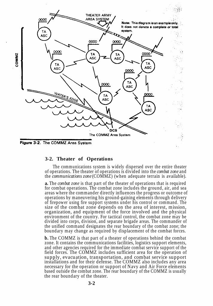
3-2. Theater of Operations
The communications system is widely dispersed over the entire theaterof operations. The theater of operations is divided into the combat zone andthe communications zone (COMMZ) (when adequate terrain is available).a. The combat zone is that part of the theater of operations that is requiredfor combat operations. The combat zone includes the ground, air, and seaareas where the commander directly influences the progress or outcome ofoperations by maneuvering his ground-gaining elements through deliveryof firepower using fire support systems under his control or command. Thesize of the combat zone depends on the area of interest, mission,organization, and equipment of the force involved and the physicalenvironment of the country. For tactical control, the combat zone may bedivided into corps, division, and separate brigade areas. The commander ofthe unified command designates the rear boundary of the combat zone; theboundary may change as required by displacement of the combat forces.b. The COMMZ is that part of a theater of operations behind the combatzone. It contains the communications facilities, logistics support elements,and other agencies required for the immediate combat service support of thefield forces. The COMMZ includes sufficient area for the operation ofsupply, evacuation, transportation, and combat service supportinstallations and for their defense. The COMMZ also includes any areanecessary for the operation or support of Navy and Air Force elementsbased outside the combat zone. The rear boundary of the COMMZ is usuallythe rear boundary of the theater.
3-2

c. The organization of a theater of operations varies with the type oftheater, the types of forces in the theater, and the nature of the operationsplanned. FM 100-10 provides a more complete discussion of the territorialcommunications zone.
3-3. Area Communications
a. In the COMMZ, units of the theater communications command (army)(TCC(A)) install, operate, and maintain an area communications system.This area communications system consists of area signal centers (nodes) sosituated throughout the theater army that a major subordinateheadquarters located anywhere in the corps rear area or the theater armyservice area has ready access to the signal communications facilities of oneof the nodes. These area signal centers are interconnected by multichannelcommunications facilities in a manner that permits routing from one areasignal center to another through several paths. The requirement of themission and the location, and size of units determine the number of areasignal centers (nodes) established in the COMMZ.
3-3

b. Also installed in the COMMZ is a command communications system.This system is superimposed on the area system to form an integratednetwork. Units of the TCC(A) install, operate, and maintain the theaterarmy command communications system. The command system hasmultichannel voice communications, radio teletypewriter, and messengerservice facilities. These facilities interconnect the theater army main andalternate signal centers and extend from these signal centers direct to
3-4

headquarters of major subordinate commands, such as the corps. Theaterarmy signal units normally furnish the teams and equipment that arerequired to terminate the theater army command communications systemat the subordinate headquarters.
c. There is only a limited requirement for single channel radio net facilitieswithin the COMMZ, but a single channel net is provided as a backup to themultichannel links for special communications. Detailed information ontheater army communications is contained in FM 11-23.
3-4. Corps Communications System
a. The corps communications system operates in the combat zone andprovides communications for corps units. It is an integrated systememploying multichannel communications facilities to provide service onboth a command and area basis plus single channel command radio. Directlinks are provided from the corps main to attached divisions and selectedsubordinate units within the corps area. The area communications systemis interconnected with the command system and consists of no more than 16area signal centers (nodes) situated to provide ready corps-wide access. Thecorps system also interconnects theater army, adjacent corps, anddivisions.
b. The corps area system may be employed as a grid, tandem, orcombination grid and tandem network utilizing no more than 16 corps areasignal centers (CASC). Usual employment is 15 CASC with one held inreserve for replacement/augmentation. Defense Communications System(DCS) entry into the system is based upon technical capability andcommand requirements.
3-5

c. Each CASC furnishes multichannel radio and wire facilities and localfield wire and cable circuits to units in the vicinity requiring the service.Each area signal center also—
(1) Furnishes telephone, telecommunications center. teletypewriter,data, cryptographic, and limited messenger services for units andinstallations in the area.(2) Provides patching and switching of telephone, teletypewriter, anddata circuits.(3) Provides radio-wire integration (RWI) and retransmission services.(4) Provides interface with the DCS at selected sites (nodes).
d. The corps command communications system normally consists of directlinks between corps main and attached or assigned major subordinatecommands. Links are also provided to the corps tactical command post(TAC CP), corps rear/corps support command (COSCOM), and adjacentcorps. For additional information on communications, consult FM 11-50,FM 11-92, and FM 24-1.
3-6
3-5. Division Communications System
The division uses an area communications system, a commandcommunications system, RATT nets, and FM single channel radio nets toprovide the commander with the necessary communications to effectivelycommand and control his troops.a. The area system provides communications for administrative,logistical, and maintenance support. It also supplements the commandsystem and provides access to the multichannel system for any supportelements located in the vicinity of an area node.b. The command system provides the means necessary for division tacticaloperations and insures the priority of command/control communications.(See FM 11-50 for additional information.)c. RATT nets are established between echelons of the division tosupplement and as backup to the command and area multichannel systems.d. Single channel FM voice nets are established between echelons of thedivision to provide the commander with a mobile, flexible means ofcommand/control during the heat of battle when time is of the essence.e. With the use of RWI stations, the commander has access to the area andcommand multichannel systems even though he may be in a remote area oran aircraft with only FM radio for communications. (See TC 24-3.)
3-7

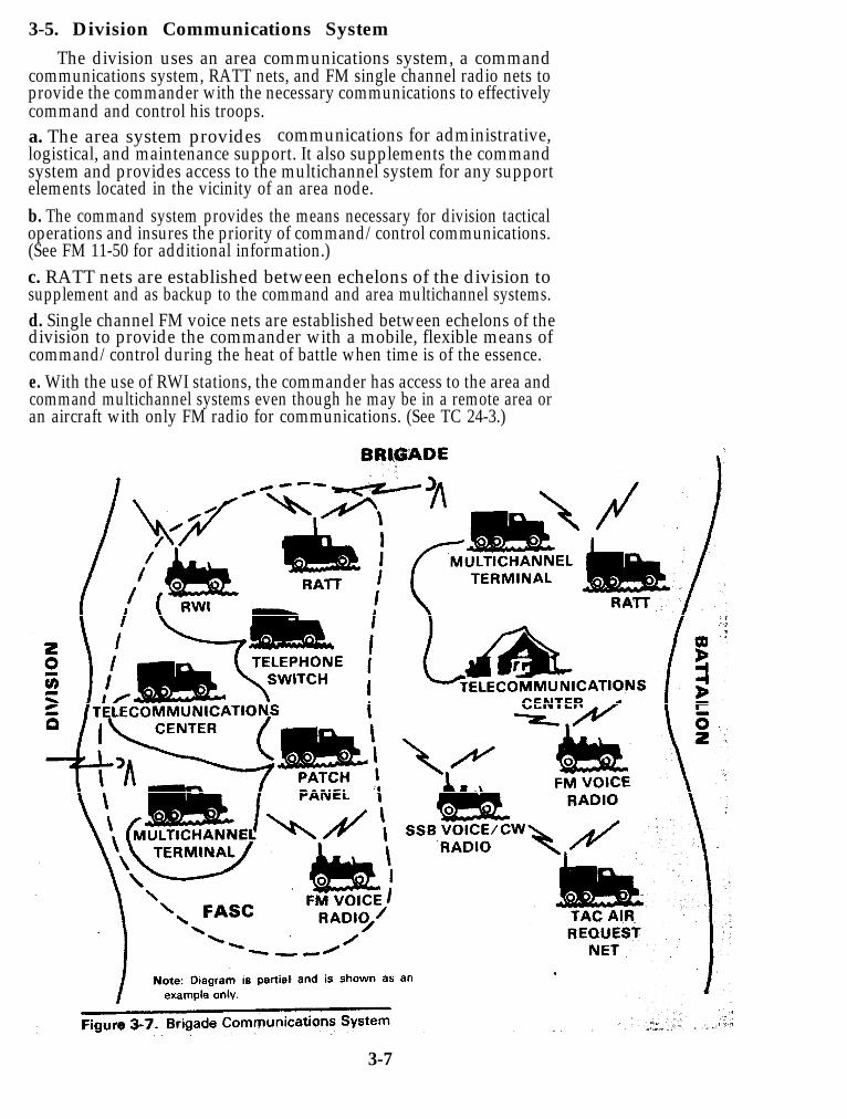
3-6. Brigade Communications System
The brigade communications system functions as an integral portion ofthe overall division communications system and serves as its forwardterminus. The brigade headquarters is connected with the main echelons ofthe division by multichannel radio and/or cable provided and operated bydivision signal battalion personnel. Forward area signal centers of thedivision provide communications links between brigade and combatsupport and combat service support units. RATT sets are used in thebrigade area to operate in the division RATT nets to supplement and backup the division multichannel system.
FM single channel radio nets are established in the brigade area andbetween the division and brigade. These radios are the primary means ofcommunications during the heat of battle when instant reaction to orders isessential to the outcome of the battle.
3-8

Chapter 4
4-1. Introduction
The tactical communications-electronicsmanagement system consists of the C-Emanagement assets assigned to eachechelon. Each level of command isresponsible for integrating its owncommunications into the system and forsupporting the overall system within thetheater of operations. The representativeorganizational structure (fig 4-1) is describedin this chapter. Note that this manualdiscusses only the relationship betweentheater and theater army C-E managementfunctions. It does not prescribe doctrine forthe theater.
4-1

4-2. Theater and Theater Army C-E Management a. The theater commander is responsible for communications of the theaterheadquarters and from the theater headquarters to and between componentservices within the theater of operations. He normally delegates theresponsibility for signal communications support to the major componentcommander and to commanders of joint task forces. In a large theater ofoperations, the theater commander may delegate the responsibility andfunction of COMMZ communications to the theater army commander.b. The theater army (TA) commander depends on his assistant chief ofstaff for communications-electronics (ACSC-E) for recommendations on C-E requirements. The ACSC-E, also known as the TA C-E officer, is in chargeof the TA C-E section. He is responsible to the commander for the overallformulation and implementation of C-E plans, policies, and procedures forthe installation, operation, maintenance, and management of the theatercommunications system (army) (TCS(A)). As the commander’s primary C-Eadviser, he forms broad policies for C-E activities and issues instructions fortheir implementation to major subordinate commanders. The TA C-Esection is the primary point of contact for coordination with the joint forcescommander, CONUS activities, and other activities concerningcommunications-electronics matters. Under the tactical communicationscontrol facility (TCCF) concept, the C-E section is the CSPFE for the theaterarmy. Personnel from the C-E section man the theater army tacticalautomatic switch control office (TASCO) along with personnel from TAsignal brigade CSPE and CSCE offices. The C-E section is composed of twodivisions:
(1) The Plans Division consists of three branches:The Electronic War-fare Electromagnetic Environment Branch.The Frequency Management and Call Signs Branch.The New Equipment Training Branch.
(2) The Operations Engineering Division consists of three branches:The Operations Branch.The Engineering Branch.The Systems Performance Analysis Branch.
4-2

4-3. Theater Communications Command (Army) (TCC(A))
a. The TCC(A) installs, operates, and controls the theatercommunications system (army) (TCS(A)) which provides both commandand area type communications. Within the theater army, subordinate unitsof the TCC(A) provide a high capacity, multimedia, multiaxis, integratedcommunications network. TCC(A) provides command and control ofassigned or attached signal units. Headquarters, TCC(A), provides theCSPE and CSCE functions for—
Planning.Systems engineering.Traffic engineering.Circuit allocation and control.Communications security (COMSEC).Liaison with the—
Defense Communications AgencyC-E staffs of other military services.Allied forces.Civilian communications agencies.
b. The TCC(A) is responsible for the COMMZ line of communications(LOC) from the rear of the COMMZ to the rear of the combat zone. TheTCC(A) employes the assets of the separate companies or battalions plusarea companies and battalions that are assigned or attached.Representative types of units used are operations battalions withmultichannel facilities, trunk switching companies, communicationscenter operations companies, and tropospheric companies; as well as otherspecially organized units tailored to provide theater army C-E support.
4-3

4-4. Corps Level C-E Managementa. Corps C-E Officer/Signal Brigade Commander. The corps C-E officer isa member of the special staff of the corps headquarters. He is also thecommander of the corps signal brigade. In both functions, he is the keyindividual in the C-E management system at the corps level.b. Corps C-E Officer Functions. In his functions as the corps C-E officer,the signal brigade commander has staff responsibility for the coordinationand supervision of the activities of all corps communications systems. Hisspecial staff responsibilities are to—
(1) Advise on communications-electronics matters including signalcommunications, locations of headquarters, and signal facilities.(2) Determine requirements for communications support and theemployment of signal troops.(3) Exercise technical staff supervision over C-E activities of thecommander.(4) Prepare the C-E and electronic counter-countermeasures (ECCM)portions of the training program.(5) Coordinate frequently allocation, frequency assignment and use,and the reporting and processing of interference problems.(6) Advises the commander and staff on matters pertaining toelectromagnetic radiation environments in the command.(7) Evaluate technical instructions; obtain advice and assistance fromC-E staff officers at higher echelons; coordinate plans and operationswith the C-E staff officer of higher headquarters; and provide technicaladvice and assistance where needed.(8) Represent the corps on planning groups to assure properconsideration of C-E support.(9) Assist in preparation of electronic warfare (EW) plans and annexes.
4-4

(10) Implement the signal security policy and procedures.(11) Plan and coordinate the installation, operation, and maintenance
of communications systems by assigned or attached units.(12) Plan and coordinate still and motion picture photographic services.
c. Corps Signal Brigade Commander Functions. The signal brigadecommander (also the corps C-E officer) controls all assigned and attachedsignal units. He directs the installation, operation, and maintenance ofcorps C-E systems and facilities required to implement plans developed bythe corps C-E staff to include—
(1) Communications system planning, engineering, and controlfunctions.(2) Technical control over all corps communications facilities.(3) The communications systems of major subordinate commandersand adjacent major US and allied commands with the communicationssystems established by the brigade.(4) Crypto logistics support coordination for the corps.(5) Coordinating support required for access to the theater armycommunications system.
d. Headquarters and Headquarters Company (HHC) of the corps signalbrigade provides the staff personnel who—
(1) Are responsible for command control, staff planning, andsupervision of signal brigade operations for the commander.(2) Form an element to plan, engineer, and control the corps commandand area communications systems.(3) Make up the corps C-E section that supports the corps staff.
e. Corps C-E Section. Although this section is assigned to the HHC of thecorps signal brigade, its duties are performed at corps headquarters underthe direction of the C-E officer. The C-E section is used by the corps C-Eofficer in the coordination, planning, and technical supervision of the corpscommunications systems. The CSPE and CSCE functions performed eitherby the C-E section at corps or by the operations section of the signal brigadeare—
(1) Long range communications planning.(2) Contingency planning.(3) Communications network layout.(4) Preparing the technical annex to theater army plans and orders.(5) Analyzing the operation of all corps systems.(6) COMSEC.(7) Issuing and controlling radio frequencies and call signs.(8) Preparing radio net diagrams.(9) Coordinating on frequency matters with the theater army C-Esection and subordinate commanders.
f. CSCE, CNCE, and CESE. The functions of these elements are providedby elements of the corps battalions as described below.
(1) The corps command operations battalion provides terminalcommunications facilities (telephone, teletypewriter, facsimile, and air
4-5

and motor messenger service) for the echelons of corps headquarters. Italso shares a responsibility with the radio and cable battalion fordisplacement of the corps command posts communications facilities.(2) The corps area signal battalions (normally four) are charged withinstalling, maintaining, and operating the corps area communicationssystem which provides the multichannel radio and cablecommunications for the combat support and combat service supportunits within the corps area. Further, the corps area communicationssystem serves as an alternate means of communications for the corpsheadquarters command system.(3) The corps radio and cable battalion controls the attached signalelements of the brigade and the single channel and multichanneltransmission facilities in the command communications system. Itprovides cable and wire support to the command communicationssystem and shares command post displacement responsibility with thecorps command operations battalion.
4-5. Division Level C-E Managementa. Division C-E Officer/Signal Battalion Commander. The division C-Eofficer is a division staff officer. He also commands the division signalbattalion. He directs all signal activity within the division and is the keyindividual in the C-E management system at the division level.b. Division C-E Section. The C-E section is also the CSPE for the division.Based upon input from the various division staff elements, it performs thefollowing functions.
Determines communications requirement.Engineers communications systems.Integrates C-E plans with tactical operations.
4-6

Prepares diagrams and map overlays.Insures COMSEC practices.Provides the signal battalion S3 with direction and guidance forestablishing the division communications system.
c. The Division Signal Battalion provides signal communications systemsand facilities for all command echelons of a division, together with specialstaff and technical assistance for planning and control of all divisioncommunications. It is staffed to provide direct support COMSEC logisticsfor the division. The operations section of the battalion HHC performs thedivision CSCE functions.d. The HHC of the organic division signal battalion, together with thecommunications-electronics staff plan, direct, and coordinate assignedoperations and required training of the division signal battalion. HHC alsoprovides command, control, administrative, and logistical support for thebattalion.e. Signal Companies of the division signal battalion install, operate, andmaintain the communications facilities of the division as follows:
(1) The command operations company (“A” company) providescommunications facilities and services for the division main, divisiontactical command post, division artillery, and artillery group.(2) The forward communications company (“B” company) providesthree forward area signal centers to support units within a designatedforward area of the division. The company also provides secondaryaccess to the division communications system for supported units in theimmediate area. The company provides the multichannel access for thebrigades of the division.(3) The signal support operations company (“C” company) providescommunications facilities for a division support area (DSA). It alsoprovides signal center support for units near the DISCOMheadquarters or near the division rear elements; and multichannelservice to the ADA, engineer battalion, and the division aviation unit.
f. Unit Communications Officers of brigades and separate battalionsperform duties similar to the duties of the division C-E officer. Generally,the duties include—
(1) Supervising the installation, operation, and maintenance of theunit’s communications system.(2) Preparing plans for displacement or extension of thecommunications system.(3) Supervising the maintenance of communications security andassisting in preparing training directives pertaining tocommunications.(4) Preparing standing operating procedures (SOP) required fortactical and technical control of the communications system.(5) Assisting in the selection of the locations of the command post andcommunications installations within the command post.
4-7

Chapter 5
5-1. Introduction
Under the C-EMS structure, the C-Eplans–and engineering–result from thestaff planning methods used to develop C-E(signal) estimates and plans. At the higherlevels of the command structure particularly,the C-E plans and orders developed provideonly general guidance in the scheme of C-Esupport.
This chapter covers the functionsinvolved in the C-E planning process. The listof functions presented here may be used as aplanning guide for using communicationsresources, to include the installation,operation, and maintenance of C-E systemsthat satisfy user requirements. The planningfunctions involve. responsibilities at allechelons; only their scope changes accordingto the planning needs of each command level.Additional information on C-E planning,procedures, and formats is in FM 24-16.
5-1

5-2. Relationship Between C-E Planning and EngineeringGeneral guidance is of little value to the equipment team installing a
circuit; therefore, at some point, planning must become engineering andprovide detailed technical information. At that point, a detailed C-E (signal)order must be issued to activate the C-E system. The C-E order must satisfythe needs established or determined during the planning phase.a. The amount of technical detail contained in the C-E order will vary withthe level at which it originates; the higher the echelon in the organizationalstructure, the less the required detail. Even at the implementing level, C-Eorders may not be specific if SOP’s and other fixed directives are availableand provide detailed implementing instructions. Obviously, if the C-Esystem can be activated with a simple, easily understood order, thecommunications needs of the supported command are more effectivelysatisfied. For this reason, standard procedures, preplanned interface, andstanding instructions are established.b. Specific functions of the planning elements are as follows:
Preparation of C-E plans, estimates, and orders.Maintenance of records.Assessment and allocation of resources.Validation of user requirements.Preferential services.Issuing technical directives.Introduction of new equipment.Frequency management.Assignment of call signs.Contingency planning.Recording user locations.System security.Provision for messenger service.Directory service.
c. Engineering functions may be identified as distinct from planningfunctions but, in reality, are often inseparable from planning. Engineeringfunctions are listed here to show their relationship to planning and arecovered in detail in chapter 6.
Network layout.Traffic engineering and diagrams.Circuit routing lists/bulletins.Traffic diagrams/bulletins.Line route maps.Multichannel systems and radio net diagrams.System performance analysis.Electronic counter-countermeasures.
Figure 5-1 shows a logical progression of planning and engineeringfunctions.
5-2

5-3. Preparation of C-E Estimates, Plans, and Ordersa. The C-E estimate is a continuing process that is seldom recorded, exceptat high command levels. However, if time permits, estimates may be kept atany level and used in preparing plans for future operations. Revision of theC-E estimate occurs constantly as new facts are introduced.b. The C-E plan is based on paragraph 5 of the C-E estimate. It containsinstructions and information about providing C-E support for the commandas a whole. Specifically, the C-E plan—
(1) Assesses the situation.(2) Defines the mission.(3) States the proposed method of execution.(4) Lists the administrative/logistical plan.(5) Lists the C-E instructions in effect and location of command posts.
5-3
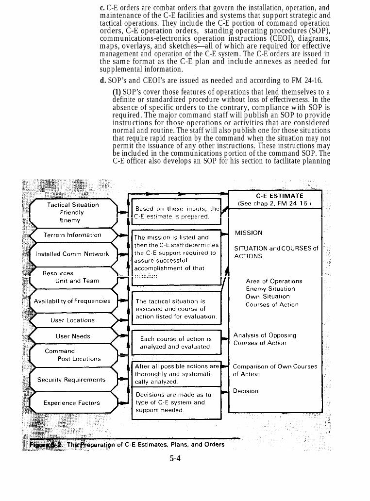
c. C-E orders are combat orders that govern the installation, operation, andmaintenance of the C-E facilities and systems that support strategic andtactical operations. They include the C-E portion of command operationorders, C-E operation orders, standing operating procedures (SOP),communications-electronics operation instructions (CEOI), diagrams,maps, overlays, and sketches—all of which are required for effectivemanagement and operation of the C-E system. The C-E orders are issued inthe same format as the C-E plan and include annexes as needed forsupplemental information.d. SOP’s and CEOI’s are issued as needed and according to FM 24-16.
(1) SOP’s cover those features of operations that lend themselves to adefinite or standardized procedure without loss of effectiveness. In theabsence of specific orders to the contrary, compliance with SOP isrequired. The major command staff will publish an SOP to provideinstructions for those operations or activities that are considerednormal and routine. The staff will also publish one for those situationsthat require rapid reaction by the command when the situation may notpermit the issuance of any other instructions. These instructions maybe included in the communications portion of the command SOP. TheC-E officer also develops an SOP for his section to facilitate planning
5-4
and operations, and to insure that all elements of the section are awareof their assigned responsibilities and instructions. The senior signalunit and each of its subordinate units will prepare SOP’s to provideinstructions for the operation of each unit. Normally, the further downthe line in echelon and operational level, the more detailed and specificthe SOP becomes.(2) The CEOI contains a series of instructions issued for technicalcontrol and coordination of communications-electronics operations of acommand or activity. The automated CEOI is prepared and publishedby the Director, National Security Agency (NSA), and shipped directlyto the COMSEC custodian of each command. Manually preparedCEOI’s are produced locally. (See AR 105-64.) Subordinate C-E officersdetermine the distribution of CEOI items within their units anddistribute the CEOI extracts required by their commands or units.
5-4. Proceduresa. The preparation of C-E estimates, plans, and orders closely parallels theplanning and decision-making cycle followed by the commander and hisstaff. For a specific operation, this cycle starts with a mission statement, acommander’s concept, and a command estimate; progresses into acommand operations plan; and ends with the issuance of a commandoperations order. The C-E officer and his staff participate directly in thedevelopment of command estimates, plans, and orders. C-E estimates aredeveloped to assist the commander in his overall estimate of the situation.b. During the planning phases, the C-E officer advises the commander andother members of his staff on the capabilities and limitations of theavailable C-E support and develops a signal plan for each tactical plan. TheC-E officer develops the instructions and information pertaining to theprovision of signal support for the command as a whole, as well asadministrative and logistics information to be incorporated into thecommand operations order. The C-E estimates, plans, and orders preparedby the major command should be concerned primarily with policy direction,operations, concepts, systems objectives, and special communicationsrequirements for the use of the senior supporting signal units andsubordinate major commands.c. Remember that for the C-E system to function properly, it must beplanned properly. And for it to be planned properly, there must be a free andcontinuous flow of information between the C-E staff and the CSCE.d. After estimates have been made, plans developed, and orders written,the orders are published, distributed, and implemented.
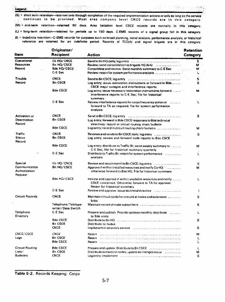
5-5. Maintenance of Recordsa. Records pertaining to C-EMS functions will be kept in accordance withAR's 340-2 and applicable 340-18 series. Table 5-1 is a summary of the typesof C-EMS records normally retained by the C-E section at major commandheadquarters and at senior signal units. The records may be in the form ofdocuments, cards, messages, diagrams, overlays, photographs, or whateverform that can be best utilized and maintained. C-EMS records will bestandardized in both format and content. Records are retained according toprocedures established by each major command. Table 5-2 is an example forcorps.
5-5

b. Permanent records will not be maintained by signal organizationsbelow TCC(A) and signal brigade levels. Permanent records for corps anddivision will be incorporated into the records of their respective majorcommands. Within a theater of operations, permanent records of C-EMSoperations pertaining to system status and performance, use of equipmentand supplies, personnel and training, experience data, and userrequirements will be centralized at theater army level or the senior combatzone command. When required, theater army or the senior combat zonecommand will supply information derived from these permanent records toCONUS. The report is called the Communications System InformationSummary.
5-6
5-7
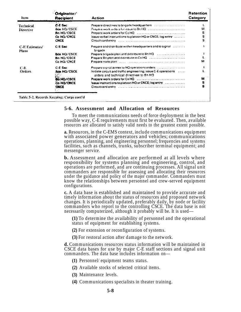
5-6. Assessment and Allocation of ResourcesTo meet the communications needs of force deployment in the best
possible way, C-E requirements must first be evaluated. Then, availableresources are allocated to satisfy valid needs to the greatest extent possible.a. Resources, in the C-EMS context, include communications equipmentwith associated power generators and vehicles; communicationsoperations, planning, and engineering personnel; frequencies and systemsfacilities, such as channels, trunks, subscriber terminal equipment; andmessenger service.b. Assessment and allocation are performed at all levels whereresponsibility for systems planning and engineering, control, andoperations are performed, and are continuing processes. All signal unitcommanders are responsible for assessing and allocating their resourcesunder the guidance and policy of the major commander. Commanders mustknow the relationships between personnel and crew-served equipmentconfigurations.c. A data base is established and maintained to provide accurate andtimely information about the status of resources and proposed networkchanges. It is periodically updated, preferably daily, by node or facilitycommanders who report to the controlling CSCE. The data base is notnecessarily computerized, although it probably will be. It is used—
(1) To determine the availability of personnel and the operationalstatus of equipment for establishing systems.(2) For extension or reconfiguration of systems.(3) For restoral action after damage to the network.
d. Communications resources status information will be maintained inCSCE data bases for use by major C-E staff sections and signal unitcommanders. The data base includes information on—
(1)(2)(3)(4)
Personnel/equipment teams status.Available stocks of selected critical items.Maintenance levels.Communications specialists in theater training.
5-8

(5) Resources in transit.(6) Status of organic communications resources of nonsignal units.
e. The CSCE supporting a signal unit makes recommendations on theallocation of resources based on system status, anticipated requirements,current and projected availability of resources, and the major commandpriorities. However, the controlling signal commander actually does theallocation using signal orders, technical directives, and similar documentsas a guide. Allocations are normally made in response to—
(1) Trouble reports.(2) User communications requirements.(3) Orders from higher headquarters.
f. While priorities for resources allocation are a command decision basedon operational necessity, the key thought in allocation is economy ofresources. Two important factors that relate to the economy of resourcesare—
(1) Alternate systems must be kept to a minimum. Maximum use ofchannel capacity must be accomplished by using common-user circuits.(2) The allocation of dedicated circuits and subscriber terminalequipment—over normal SOP distribution—must be closely monitored.
5-7. Responsibilities for Assessment and Allocationa. For assessment and allocation to be fully effective, guidelines must beestablished by the headquarters of the highest echelon signal organization.The guidelines should delineate—
(1) Responsibilities.(2) Delegation of authority to commit resources.(3) Issuance of specific instructions as to the extent a unit may expendits capability (including the numbers and types of teams for whichcommitment may be made without referral to the next higherheadquarters). This applies particularly to system restoral actionsexecuted on the basis of system integrity and operational priorities.
b. To insure adequate responsiveness and flexibility in providingcommunications support, the extent of the commitment of communicationsresources by the next subordinate command will be established by eachcommand echelon. The extent of commitment will be between 80 and 90percent of available resources. Authority to commit resources to thethreshold level should apply both to installed and uncommitted equipmentand to personnel. When requirements for resources cross command lines,the decisions will be made by the headquarters with control over the unitinvolved.c. In planning for the effective employment of the allocated resources, thetime element is a major governing factor, especially where restoral action isconcerned. Calculations for restoral of service must consider the point ofavailability of the resources and travel time to the point of installation. Forexample, a shelter in a transportable configuration may be removed fromits prime mover and transported by heavy lift helicopter, while the organicvehicle proceeds to the site by road.5-8. Validation of User Requirementsa. A tactical communications system must be designed and operated onlywithin unit capabilities and only in direct response to the tactical mission.
5-9

Unit commanders and their staffs must neither request nor plan upon acommunications system that exceeds the primary needs of the unit. Basicuser (unit) requirements for communications are broadly prescribed inArmy doctrinal publications and are reflected in the basis of issue (BOI) ofterminal equipment authorized for user units. User requirements are alsoreflected in the amounts and capacities of switching and transmissionequipment authorized for signal units providing C-E support.b. The planning and engineering of a communications system formaximum effectiveness within available resources require preciseidentification and validation of user requirements.
(1) In the command communications system, most requirements arefixed, known in advance, and subject to little change.(2) In the area communications system, requirements for common-usersupport are not as fixed as in the command system. Requirements willvary with troop deployment and changes in support of unit locations.(3) The theater army C-E section will identify requirements for basiccommunications circuits and for support of the army in the field. Thesection will publish these requirements in an SOP as guidance formajor commands and their supporting signal units.
c. The types and amounts of access communications to the command, area,and theater systems will be prescribed for the combat, combat support, andcombat service support units on the basis of published doctrine, if available,or experience factors. In this way, a baseline network can be designed andinstalled to satisfy minimum essential user requirements. In addition tobaseline requirements, tactical situations and changing environmentsrequire that a means be provided for users to obtain changes to their normalcommunications support when necessary.d. The validation of new requirements begins when the potential usersubmits a request, either oral or written, to the CNCE supporting the unitinvolved. The CNCE grants the request if it has the capability andauthority. Otherwise, the CNCE prepares a special communicationsauthorization request (SCAR) and submits it to the next higherheadquarters and subsequently to the unit with the resources to grant therequest. Figure 5-3 shows the procedures for validation of userrequirements.5-9. Preferential Services
Preferential services are provided to users (usually select users) toinsure continuity of operations or to improve responsiveness to situations.a. In tactical C-E systems that employ manual switching, preferentialservices are usually provided either by dedicated circuits or by callsupervision by telephone operators. Automatic switches, however, can anddo provide preferential service by selective programing; there is no need touse dedicated services or the operator.b. The following are some of the preferential services that can be providedby automatic switches.
(1) Assignment of precedence and preemption capability.(2) Call forwarding.(3) Conferencing (preprogramed, progressive, and broadcast).(4) Off-hook service (direct access capability (DAC)), sometimes calleda hot line.(5) Assignment of a fixed directory number to selected mobilesubscribers. 5-10

c. Since the demand for preferential services usually exceeds the capabilityof the equipment, the services must be limited to those who really need them.Initial requests for preferential services should be submitted to the systemplanner during the design phase of the C-E system. After the C-E system isestablished and as the need arises, a potential user may submit a specialcommunication authorization request (SCAR) to the commander of thenode serving the user’s organization. The decision on who gets preferentialservice will be made at the major command level. Authorized preferentialservices will be included in the SOP of the supporting signal unit and will bereflected in instructions to the CNCE’s and automatic switches involved.
5-10. Issuing Technical Directivesa. A technical directive is used to initiate, govern, or order a certain action,procedure, or policy. The directive may be either oral or written; the lowerthe echelon, the more likely they are to be verbal directives.
b. For efficient functioning of the C-E system, there must be an unrestrictedflow of technical information between C-EMS elements. Thus, technicaldirectives are issued at all C-EMS echelons (fig 5-4) to provide amplifyinginstructions on procedures, standards, methods, and techniques used toimplement major C-EMS decisions. Directives are also used to assist insystem coordination and uniformity of operations. Guidelines on issuingand recording technical directives are as follows:
c. Technical directives are issued by C-E sections of major commands or byCSCE’s to subordinate counterparts or signal units. Those directives that
5-11
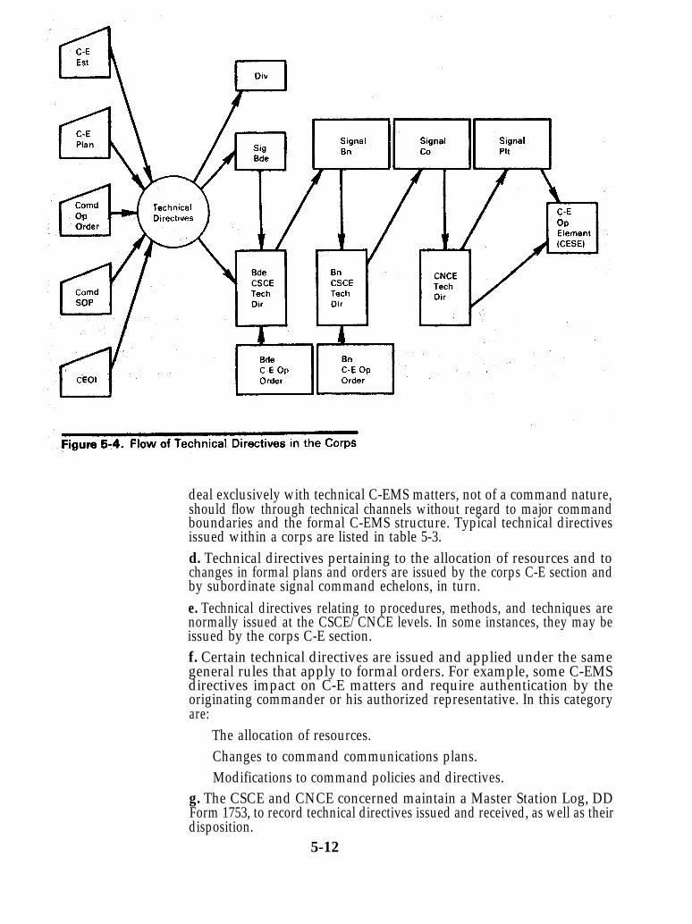
deal exclusively with technical C-EMS matters, not of a command nature,should flow through technical channels without regard to major commandboundaries and the formal C-EMS structure. Typical technical directivesissued within a corps are listed in table 5-3.d. Technical directives pertaining to the allocation of resources and tochanges in formal plans and orders are issued by the corps C-E section andby subordinate signal command echelons, in turn.e. Technical directives relating to procedures, methods, and techniques arenormally issued at the CSCE/CNCE levels. In some instances, they may beissued by the corps C-E section.f. Certain technical directives are issued and applied under the samegeneral rules that apply to formal orders. For example, some C-EMSdirectives impact on C-E matters and require authentication by theoriginating commander or his authorized representative. In this categoryare:
The allocation of resources.Changes to command communications plans.Modifications to command policies and directives.
g. The CSCE and CNCE concerned maintain a Master Station Log, DDForm 1753, to record technical directives issued and received, as well as theirdisposition.
5-12

5-11. Introduction of New EquipmentTo meet the constantly changing needs of the tactical situation, new
C-E equipment is continuously being designed, produced, tested, andintroduced into the field. The objective is to provide improved technicalcapabilities in our communications system. In the process, new items mustbe introduced into the system with a minimum of confusion and disruptionof service to users. Normal practice is to keep both the old and the newequipment operating in parallel. This allows continuance of service to theusers and, at the same time, provides training time to operators andmaintenance personnel. Then, as time—usually a specified time frame—goes by, the old items are withdrawn, evacuated, and either reissued to other
5-13
units that need them or packed and shipped to CONUS. Security is of primeimportance and every effort must be made to keep the enemy fromdiscovering whatever unique capabilities are provided by the newequipment.a. Organizational levels of responsibility. A primary requirement in theintroduction of new equipment is close coordination between CONUSplanning personnel and theater army personnel. Shipping schedules,deployment phasing, logistical support, personnel, training, and use of newequipment training teams (NET) from CONUS sources should be closelycoordinated. Prior to introducing new equipment, appropriate C-EMSelements should make detailed assessments of the operationalcharacteristics and interface requirements for new equipment and thenprepare the necessary changes to C-EMS policies, methods, and procedures.
(1) Theater Army. Within the COMMZ in a theater of operations, thetheater army C-E section will control the introduction of newcommunications equipment.(2) Corps. Within the combat zone, the corps will handle theintroduction of new equipment.(3) Division. The C-E sections of both corps and division willcoordinate the introduction of new equipment for units in theirrespective commands.
b. Staff responsibilities. Each major command C-E staff is responsible forinsuring that adequately trained personnel for both operation andmaintenance, along with repair parts, special test equipment, anddocumentation, are available before commitment for operation is given.The major command C-E staffs also provide wide distribution of newequipment phasing-in schedules to insure smooth transition from old tonew. As new equipment replaces old equipment, inventory changes must beupdated and reported on the operational resources report.
5-12. Radio Frequency ManagementRadio frequency resources (channels of the frequency spectrum) are in
critically short supply and their use requires closely controlled, propermanagement. And because radio frequencies are so important, theirallocation and assignment is a command function and a commandresponsibility. Each command must implement effective control proceduresto insure that electromagnetic emissions conform to the policies of thehigher headquarters.
The essential factors that must be considered in operational planninginclude frequency requirements and availability, assignment priorities,and geographic and technical limitations. Whenever possible, frequencysharing should be used. This can be accomplished through propermanagement, control, and training. Careful planning and management isa must to prevent mutual interference or saturation of any portion of theradio spectrum.
5-13. International Frequency ControlUse of the radio frequency spectrum in all countries is governed
through the United Nations (UN). The controlling agency of the UN is theInternational Telecommunications Union (ITU) which, through periodicinternational conferences, concludes treaties regulating the use of the radiospectrum, obtains standardization of methods and procedures, andminimizes interference. In addition, most ITU member countries imposeadditional regulatory measures beyond those required by international
5-14

treaty. Only those frequencies assigned and approved by the host countryare to be used.a. When the host country for US forces has a controlling government, theallocation of frequencies within that country is under the control of thatgovernment. Allocation and use of frequencies are diplomatic matters thatare resolved by the heads of state or the official representatives of thegovernments involved.b. After a base of operations is established in the host country, the taskforce commander continues negotiation on frequency allocations with thegovernment of that country.5-14. Frequency Management Channels
In all overseas commands involving large geographic areas andemploying two or more armed services, a unified command is established—a theater of operations. The major Army, Navy, and Air Force headquartersare component commands within the theater.
Frequency management in an overseas area is under the control of thehighest command present. If it is a unified command, the Joint Chiefs ofStaff (JCS) provide policy guidance and the theater commander providesguidance to the component commands. Figure 5-5 shows the JCSmanagement channels.
5-15. Theater Level Frequency Management
The theater commander exercises control over radio frequency usagewithin the theater through his joint staff. The Director of CommunicationsElectronics (J6) has primary staff responsibility for frequencymanagement in the theater. The office of the J6 includes a frequencymanagement section with a trained frequency management officer as thesection chief. He and his staff are responsible for the allocation andassignment of all frequencies used by US forces within the theater or zone ofoperations.
5-16. Theater Army Frequency Management
a. Theater Army (J6) Section Functions. The Frequency Allocation andCall Signs Branch, Plans Division, of the theater army C-E section isresponsible for summarizing the frequency requirements of all subordinatecommands. The branch then prepares frequency allocation lists which arepublished as the Frequency Allocation and Usage (FAU) list of the unifiedcommand. Thus, the branch performs frequency planning, coordinates theuse of frequencies, and publishes frequency information to subordinatecommands. In performing its functions, the branch participates infrequency planning with both higher and lower commands, and helps toinsure that the policies and directives of higher echelons (fig 5-5) are beingfollowed. The Frequency Allocation and Call Signs Branch also maintainsrecords of frequency assignments, including a master list of frequency andcall sign allocations and assignments for the entire Army area ofoperations.
b. Theater Communications Command (Army) (TCC(A)) Functions. TheFrequency Allocation Branch of the J-6 section (CSPE) in the TCC(A)manages radio frequencies for the TCC(A). The branch is the primary pointof contact in the TCC(A) for all radio frequency assignment actions. Thebranch coordinates frequency requirements and forwards authorizedassignments to TCC(A) operating units. It also maintains records, preparesreports, and initiates all required actions regarding radio frequency mattersfor the TCC(A).
5-15

NOTE: In the standard C-E management structure, the TCC(A) ranksas a subordinate command of theater army and receives its frequencyallocation through the TA C-E section (J6). In turn, the TCC(A) allocatesfrequencies to other TA subordinate commands for operation of the TCC(A).managed theater communications system. However, the theatercommander may elect to have the Frequency Allocation Branch, TCC(A),perform all frequency managent for the theater.c. Frequency Management Considerations. Higher echelons (fig 5-5) andthe host country may impose frequency and frequency related restrictionson theater army. These restrictons, plus those of the TA commander, will,in turn, be reflected in the frequency assignments and allocations to lowerechelons. Generally, restractions are related to the size of the TA area ofoperations, the requirements of the host country and allied forces, the typesand quantities of equipment being operated, the limited frequency spectrum
5-16
available, requirements for strategic communications, etc. The followingitems are typical of factors that must be considered in frequencymanagement at the theater army level.
(1) Because requirements for tactical FM frequencies will greatlyexceed their availability, frequency sharing must be used. Thefrequency list technique of assignment and allocation and interferencecharts must be used to avoid mutual interference.(2) Subordinate TA units must submit justified frequencyrequirements at least 90 days prior to the date of anticipated use. If thisis not possible, current assignments may be used until requests areprocessed and authorized. The TA commander is responsible for properuse of frequencies.(3) The higher command will allocate multichannel frequencies totheater army based on the operating frequencies of the equipment usedin the theater. Restrictions on multichannel frequencies may beimposed by the host country or because of their use by other US forcesand allies in the TA area.NOTE: The ABM plan (FM 24-2) or other effective method of
frequency assignment must be applied to obtain maximum use of eachavailable multichannel frequency.
(4) Theater army must obtain individual approval for all HFcommunications that use skywave propagation or that transmits atmore than 500 watts from:
(5)
The joint force (theater) commander;The joint frequency panel (J/FP) of the US Military C-E Board(MCEB);The Allied Radio Frequency Agency of NATO;The host country; or,A representative combination of the above.For HF communications that transmit at 500 watts or less, theater
army must obtain a list of cleared frequencies from the joint force(theater) commander.(6) For AM air-to-ground, tropospheric scatter, and satellitecommunications, the joint force (theater) commander or theDepartment of the Army provides frequency allocations on anindividual basis to TA.(7) The joint force (theater) commander provides a list of authorizedFM frequencies (30-76 MHz) to TA. Restrictions imposed by the hostcountry and special operations will be included.
5-17. Corps Level Frequency Management
The corps C-E officer is responsible for providing radio frequencymanagement support to all corps units and coordinates with theater armyelements operating in the corps area. The Frequency Allocation Branch ofthe corps C-E section, under the supervision of the corps C-E officer,performs the frequency management functions. The section consolidatesthe justified requirements of all subordinate divisions and attached unitsand submits a request for frequency allocations to theater army. Within theFrequency Allocation Branch, the radio frequency officer, assisted by thearea communications chief NCO, coordinates frequency allocations,assignments, and use. His duties include but are not limited to:
5-17

a. Coordination of the implementation of the automated CEOI and otherdirectives from theater army.b. Coordinating frequency allocations and call signs with subordinatecommands of the corps.
NOTE: When the CEOI is manually prepared, the radio frequencyofficer is directly responsible for implementing the CEOI and allocatingfrequencies and call signs, as opposed to a coordinating function. (See AR105-64.)c. Representing corps at radio frequency management conferences ofhigher headquarters.d. Resolving the interference problems of subordinate units referred to theFrequency Allocation Branch for solution. All problems are reported tohigher headquarters.e. Maintaining records of all frequency assignment within the corps areaof operations.f. Receiving, processing, and forwarding to higher headquarters the radiofrequency requirements for all C-E operations in the corps area.5-18. Division Level Frequency Management
The division C-E officer, who is also the division signal battalioncommander, is responsible for frequency management within the division.He supervises the division C-E section which includes a radio officer who, inturn, performs/supervises the frequency management functions as follows:a. Determining the frequency needs of the division prior to moving into anarea of operations. A list of the types and numbers of emitters to be used issubmitted to the corps C-E section, along with a request for frequencies.b. Resolving interference problems within the division. Unresolvedproblems are referred to the corps C-E section.c. Making frequency and call sign assignments to assigned and attachedunits of the division. Assignments are selected from the list of frequenciesand call signs authorized by corps. Normally, subordinate units of thedivision are permitted to use only their assigned operational frequencies.However, the brigade commander may authorize a changeover to sparefrequencies when interference occurs. The division radio officer is notifiedimmediately about the interference problem and the changeover.
NOTE: When an automated CEOI assigning frequencies and callsigns is used, the division radio officer is responsible only for its distributionand coordinating its implementation. In cases of interference, he forwardsreports of changes to alternate frequencies and call signs to the corps C-Esection.d. Coordinating with the radio officers of the other divisions to establishcommon frequency usage and to solve interference problems.5-19. The Automated CEOI
The National Security Agency (NSA) prepares, publishes, andforwards the automated CEOI to theater for further, controlled distributionwith the theater. The automated CEOI is based on input frequencyrequirements and unit lists within the theater which are submitted to NSA(or gathered by ASA teams). A computer is used to assign both frequenciesand call signs on a randomly accessed, nonpredictable basis. This precludesduplication of call signs and minimizes the interference of frequencies. TheCEOI includes alternate frequencies for use in isolated cases of interferenceproblems.
5-18
a. Call Signs. The automated CEOI includes call signs which are assignedto a unit, not to a net. Each call sign is a letter-number-letter (LNL)combination that is pronounced phonetically; e.g., A1B is alpha one bravo.Two-word call signs (as described in ACP 119) will no longer be used. Thesystem of randomly assigned, daily changing suffixes (similar to thetelephone directory arrangement) is used to expand the basic LNL call sign.b. Changes to the CEOI. The C-E officers at division, corps, and theaterarmy are responsible for the management of call signs and other aspects ofthe automated CEOI. Each C-E officer distributes CEOI material to thesubordinate using units and is responsible for its proper use. Routinechanges to the CEOI, such as additions, deletion of authorized frequencies,changes in organizations, etc., may be forwarded direct to NSA or throughthe ASA support teams.5-20. Contingency Planning
a. Contingency planning is performed continually at all echelons toprovide direction in anticipation of force redeployment or specificemergency situations that could disrupt or threaten the continuity ofcommunications networks. Its purpose is to insure the rapid establishment,restoration, or rerouting of both user and C-EMS communications.Contingency planning should be included in the planning and design of acommunications system or installation to insure its reliability; or, may be inresponse to planning requirements originated within the C-EMS structureto cover specific situations.b. Communications reliability is the first consideration in all planning. Toinsure reliability, the C-E planner must provide a communications systemwith alternate means; train personnel to operate equipment properly duringsituations of stress and emergency; include in SOP’s the requirement fordispersion and protection of critical communications facilities; and providesupply and maintenance support to reduce circuit outages to an absoluteminimum.c. The C-E officer is responsible for C-E contingency planning within amajor command and provides planning guidance to subordinate signalunits. The contingency plans of senior supporting signal units should bereviewed and approved by the C-E officer of the major command. Normally,the C-E officer of the major command will issue a planning directivespecifying the conditions that constitute the contingency requirements.Typically, the conditions are damage resulting from enemy action, weather,a disruption due to fire, equipment failure, or other catastrophe. Theguidance should also specify the degree of damage to be considered, such asloss or damage to a major equipment item, an entire node, or an extensionlink. Planning constraints are also provided regarding available resourcesand restoration priorities. Based on the guidance in the planning directive,appropriate echelons within the C-EMS structure will prepare contingencyplans.d. The major command contingency plan will generate the development ofimplementing plans by subordinate units. Specified restoral actions mayinclude patching and rerouting, institution of restriction measures, orreplacement of major equipment configurations and operating teams.Included in the contingency planning process is the requirement to dry-runthe plan to determine its effectiveness and to provide a basis for requiredmodifications.e. Contingency planning must include a COMSEC element. Emergencyplans must be prepared for use in case of natural disaster, enemy attack,and/or civil riot or uprising. Refer to AR’s 380-40 and 380-41 for additionalinformation.
5-19
5-21. Recording User Locationsa. Information regarding the location of users of communications facilitiesis essential both for accurate planning and engineering of communicationssystems and for communications support by communications nodes.Planners must be aware of all locations of supported users to include alliesand other US forces, as well as Army units. User locations become moredefined and detailed as an operation progresses and as informationbecomes available about current and future command post locations, toinclude main, TAC, etc.b. C-EMS elements and the user have joint responsibility in recording userlocation: the user must report his current and planned locations; and, the C-EMS elements must keep all units involved in supporting the user aware ofthe locations.
(1) The C-E section of each major command maintains records of userlocations and provides information to senior signal units concerningfuture unit arrivals, departures, and movements as soon as theinformation becomes available.(2) The CSCE’s maintain information on locations of major commandheadquarters, separate command headquarters, brigade, and groupheadquarters supported by the communications system for which theyare responsible.(3) The CNCE’s provide the locations of supported units by reportingunit arrivals or departures to controlling CSCE’s usingtelecommunications service orders (TSO) or special communicationsauthorization requests (SCAR) if communications service for new unitshas not been planned.
5-22. Security
a. Both communications security (COMSEC) and system security areresponsibilities of the commanders at all echelons. And although the C-Eofficer at each echelon acts for the commander in all matters pertaining toCOMSEC and system security, security is everybody’s business—from thehighest commander to the lowest ranking enlisted person.b. COMSEC is the protection that results from all measures designed todeny unauthorized persons any information of value which might bederived from the possession and study of telecommunications; or, tomislead unauthorized persons in their interpretation of the results of suchpossession and study. COMSEC includes:
(1) Cryptosecurity.(2) Transmission security.(3) Emission security.(4) Physical security (of communications security materials andinformation).(5) The security of unclassified material which, if pieced together withother material, might reveal classified intelligence.(6) Accounting for COMSEC material and CEOI items, to includemaintaining records and data on COMSEC practices essential tomaintaining required standards of system security. Data processingmethods should be used for accounting purposes.
c. System security must be considered during the planning, engineering,and control of the communications system. It is especially important inlaying out the network and disseminating information. Security is also a
5-20

prime consideration in assigning frequencies and call signs (implementedby automated CEOI). System security includes:
(1) Specifying physical security requirements.(2) Insuring availability of appropriate COMSEC material (ciphers,codes, cryptographic equipment, key lists, key cards, etc.).(3) Specifying procedures for insuring security, such as the maximumtime periods between call sign, frequency, and cryptographic keychanges (if not specified in the automated CEOI).(4) Preparing policies to implement AR 380-40 and AR 380-41regarding the accounting for and safeguarding of COMSEC material.(5) Analyzing traffic to insure proper use of COMSEC capabilities.
(6) Engineering the communications system to insure communicationsecurity (for example, meeting “TEMPEST” and other standards).
(7) Insuring the reporting of COMSEC violations and of practicesdangerous to security.
d. At the national level, the US Communications Security Board (USCSB)establishes national COMSEC policy which is amplified and promulgatedby Army regulations (AR’s). C-EMS system security measures areestablished under the national COMSEC policy; they also comply withdirectives promulgated by the Department of Defense (DOD).
e. The theater commander is responsible for the enforcement of COMSECin the command. He is assisted and advised by the theater C-E officer.Within the theater, C-E officers of major commands and commanders ofsignal units are responsible for integrating COMSEC policies andprocedures into all C-EMS functions, from planning throughimplementation.
5-23. Messenger Service
a. Messenger service is the most secure means of communicationsavailable to all units. It is the most effective method for the transmissionand delivery of bulky items. Although it is flexible and reliable, its speeddepends on the mode of travel (foot, motor, or air), tactical situation, andterrain trafficability. Messenger service complements the multichannelcommand and area systems. It is used to insure continuingcommunications and to provide service not available or permitted overmultichannel links.b. Messenger service may be either scheduled or special.
(1) Scheduled service is used when unit locations are stable and whenunit volume is large.
(2) Special messengers are used when either more rapid service orspecial handling is required.
c. The commander of the senior signal unit is responsible for operating amessenger service for the major commands in both the command and areasystems (table 5-4). The C-E section of each major command establishes therequirements for messenger service and publishes the routes, schedules,and message relay points (in the C-E annex).d. The commander of each communications node is responsible for thedirect supervision of the messenger service provided by the node, for
5-21

coordination of schedules to meet location conditions, and for providingspecial messenger service.5-24. Directory Servicea. Directory service is the preparation and distribution of telephonedirectories for and to all users of the tactical telephone system. Thedirectories contain information concerning use of the directories and of theautomatic telephone system. They include the assignment of telephoneswitchboard designation names and subscriber telephone numbers.b. The preparation and updating of directories are currently performedmanually. When facilities become available, these actions will be performedby automatic data processing. The distribution of directories is usually oneechelon up, two echelons down, and to adjacent echelons.
5-22

c. A master directory (table 5-5) is prepared, published, and distributed bythe C-E section of the TCC(A). It provides users with a basic understandingof the tactical telephone system (automatic or manual) and instructions onhow to use the system.d. The regional/unit directory is an extract from and an extension of themaster directory. It is prepared, published, and distributed by the C-Esection of major commands below theater.
5-23
Chapter 6
6-1. Introduction
The purpose of C-E systems engineeringis to use the available C-E resources in a waythat best satisfies communicationsrequirements. The goal of the C-E systemsengineer is to provide the highest grade ofservice and the shortest message delay timewith available facilities and personnel.
6-1

6-2

6-3

6-2. Network Layout
a. The C-E systems engineer prepares the network layout which is aschematic diagram of the multichannel communications system showingthe nodal and interconnecting link configuration. The multichannelnetwork layout reflects the commander’s concept of future operations. Itprovides the basic guidance for engineering the command and areamultichannel communications systems and for preparing circuit routinglists, and traffic and radio diagrams. Before an operation begins, thenetwork layout is issued as a planning document to the supporting signalorganizations and to higher, adjacent, and subordinate major commands.b. The accuracy of the network layout depends on an extensive and currentdata base which should include the following:
(1) User locations and requirements.(2) Available C-E resources.(3) Current status of existing networks.(4) Terrain conditions.(5) All available data on the enemy.
c. An extensive and reliable database, constantly being updated, is a mustfor developing the network layout, traffic, and circuit and systemsdiagrams. The C-E section of each major command, with planning andengineering assistance from the senior signal units, performs the networklayout for the command. The elements involved and the logical sequence ofactions in laying out a corps area system network are summarized in table6-1.
6-3. Traffic Engineering
Traffic engineering is the process of determining the anticipated trafficflow in a new multichannel system and the best distribution of C-Eresources to accommodate a traffic routing plan that will handle the flow.Traffic engineering continues after the system is operational by analyzingthe actual traffic flow to determine problem areas and deficiencies andtaking corrective actions. It may sound simple but traffic engineering hasits own peculiar complexities and must be performed systematically asdescribed below and summarized in figure 6-1.a. Determine Requirements. The data base and the network layout providethe basic information required for traffic engineering. Determinable factorsthat affect the traffic flow plan are user requirements for teletypewriter,data, and telephone services. These factors must be related to the speed andgrade of service objectives to determine the needs for dedicated andswitched circuits. Remember that the initial design of the network isinfluenced by the busy-hour, rush-period loads. At times, the traffic offeredto the network (system) may reach peaks above that for which it isengineered. To cope with this imbalance between the offered load andavailable facilities, restrictive measures may be required (and planned for)during high traffic periods and when portions of the network are damaged.b. Tandem Switching and Path Access Analysis.
(1) After establishing circuit requirements, determine the desirabilityof tandem switching and the needs for alternate paths. The use oftandem switching reduces the overall circuit requirements butincreases the telephone switch traffic loads.
6-4
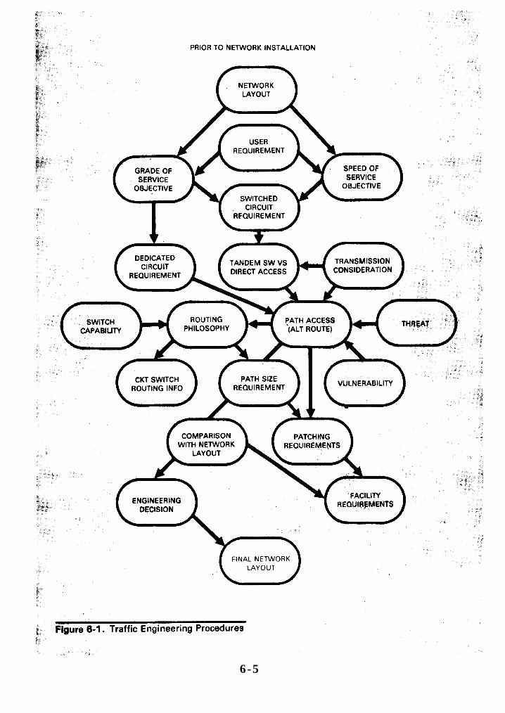
6-5

(2) Path access analysis is based on the estimated enemy threat andthe vulnerability of the signal installation. The objective of the analysisis to determine the requirements for alternate routing means.
c. Routing Plan. Develop a routing plan after the tandem switching andpath access requirements are established. In a new network (based onestimated or anticipated traffic data), the primary routes are usuallyselected on a least-cost or minimum circuit-miles basis. The capabilities ofthe switches for alternate routing and routing control (originating office orspill forward), and call shuttle hazards must also be considered. In addition,special routing requirements at communications interface points must beaccommodated by the routing plan. For example, the routing may permitcommand system traffic to enter an area system but prohibit area systemtraffic from entering the command system.d. Network Adjustments. After the routing plan is devised, determine thepath size requirements and develop instructions for the routing program ofeach switch. Next, determine the patching requirements and compare thepath size requirements with the available facilities as designated in thenetwork layout. Based on the comparison, make appropriate adjustmentsin the facilities requirements and modify the network layout accordingly.e. Traffic Analysis. After a network is installed and operational, the trafficengineer continually analyzes its operation to determine problem areas and
6-6

areas for improvement of the service. The analysis is based on inputinformation obtained from metering devices that measure the various kindsof traffic in the network and permit a qualitative and quantitative view ofits operation. Most of the required information is provided in the TrafficStatus Report (app C). Metering at tactical automatic switches (TAS) isdescribed in an appendix of FM 24-26. The main objectives of trafficanalysis are to:
(1) Change network facilities and systems, if necessary, toaccommodate required traffic. This may lead to an expansion orcurtailment of certain facilities.(2) Decide if and how the routing plan must be changed.
6-4. Traffic Engineering Responsibilities
Traffic engineering for multichannel communications supporting theArmy in the field is performed primarily at the theater army and corpslevels.a. Traffic engineering is performed by the:
(1) TCC(A) CSPE for theater army command and areacommunications systems.(2) Corps signal brigade CSCE for command and areacommunications systems in the combat zone down to the division level.(3) Division signal battalion CSCE for the division communicationssystems.
b. When tactical automatic switches are employed:(1) The TCC(A) and signal brigade CSCE's coordinate the automaticswitch data base changes for the COMMZ and combat area.(2) In the combat zone, the database changes for automatic stitches atcorps nodes and division main will be coordinated by the corps signalbrigade CSCE.(3) The corps signal brigade CSCE must include the automaticswitches in the combat area in its traffic engineering. It will receivetraffic status reports for the switches from the corps and the divisionsignal battalion.
6-5. Telephone Traffic Engineering
a. Manual and Dial Central Offices. The important aspects of trafficengineering for manual and dial central offices are trunk group planning(fig 6-2) and determining operator position requirements. The proceduresfor obtaining and using traffic data for engineering networks with manualswitching controls are covered in TM 11-486-2. Although TM 11-486-2establishes traffic engineering standards for fixed communicationsnetworks, the standards may also be used as guides for tactical systems.b. Tactical Automatic Switches (TAS). During the transition from manualto fully automated telephone networks, the problems of integrating thesystems involved (interface requirements, PR-SL assignments, routingcontrols, etc.) generate a need for flexible management procedures. Forexample, the TAS is an important factor in systems control because of itsability to provide preferential services and implement restrictive measures.Also, metered traffic data should flow directly from the TAS’s to controllingCNCE(M)’s with information printouts going to appropriate CSCE’s. Thepoint is that managers must be thoroughly familiar with the operation andmanagement of both manual and automated systems.
6-7

6-6. Teletypewriter/Data Traffic Engineering
a. Teletypewriter Traffic. The teletypewriter trunking plan must bedesigned to accommodate the required speed of service and traffic volume.At the same time, the number of message switching processes betweenteletypewtiter facilities should be kept to a minimum. Since routine anddeferred teletypewriter traffic can be delayed, the load curve (amount oftraffic, by precedence, transmitted throughout the day) and the timerequired to clear the traffic (speed of service) must, be carefully considered inplanning. The traffic engineer should plan to use the periods of minimumtraffic to accommodate the low precedence traffic that is normally delayedduring busy hours. This procedure permits channels to be selected on anaverage-hour basis rather than a peak period or busy hour basis.Procedures for deveoping the teletypewriter trunking plan (fig 6-3) arecovered in TM 11-486-2.
6-8

6-9
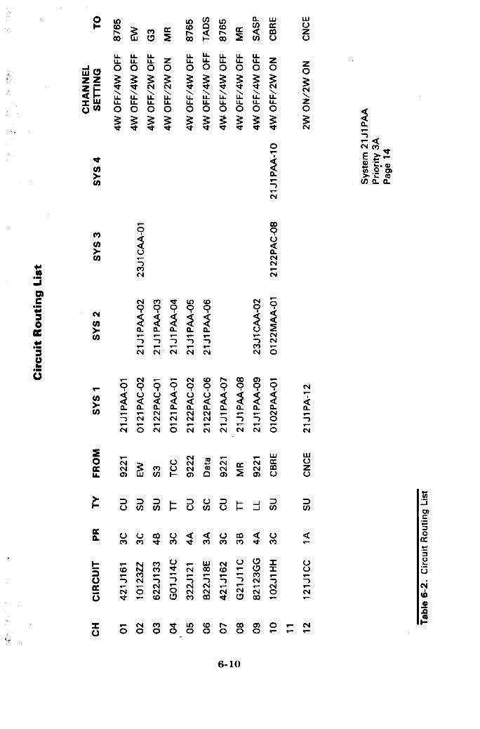

b. Data Traffic. Planning for data trunks is similar to planning forteletypewriter trunks. Data trunks, however, are more critical in that theyrequire wider bandwidth and higher quality circuits.6-7. The Circuit Routing List/Bulletin
A circuit routing list (table 6-2) provides detailed information requiredfor interconnecting system components. It also provides the patchingarrangements required for telephone, teletypewriter, and data circuits in amultichannel communications network. A circuit routing bulletin provideschange information to an existing circuit routing list. Changes may also bepublished as replacement pages to the circuit routing list using the formatshown in table 6-2 and appendix C.a. Preparation. The C-E staff prepares circuit routing lists and bulletinsissued by divisions and higher echelons. The C-E officer at each echelon isthe responsible individual. Above division level, the C-E section is assistedby systems engineering personnel of the senior signal unit supporting theechelon.b. Input Information. Preparing a circuit routing list or bulletin requires adetailed knowledge of the status of all resources, as well as the decisionsmade in preparing the network layout and in traffic engineering. Thisinformation is maintained in the CSCE supporting the major commandand is updated continuously as activation/deactivation reports arereceived from the CNCE(M)’s.c. Distribution. The circuit routing list is distributed as a part of a technicaldirective to subordinate CSCE’s and CNCE(M)'s for implementation. Thetechnical directive is a basis for orders to operating teams for equipmentinstallation, wire and cable installation, and patching at the appropriateCNCE(T)’s.d. Changes. Changes to the circuit routing list may be directed by a CSCEor they may be the result of circuit actions at a node which has delegatedauthority to initiate changes. When circuit changes are implemented at anode, they are reported in telecommunications service orders and troublereports. Changes to circuit routing lists are posted at each CSCE andCNCE(M) immediately after the changes are implemented.6-8. Traffic Diagrams
A traffic diagram is a schematic representation of traffic routinginformation. The purpose of a traffic diagram is to provide a simplifiedreference for determining trunk routing within the communicationsnetwork. Separate diagrams are used for telephone (fig 6-4) andteletypewriter/data (fig 6-5) networks. Traffic diagrams are typical ofcircuits installed but do not prescribe the exact circuits installed in everysystem. The diagrams should show the traffic flow among all elements ofthe major command and the principal routes to other networks andinstallations.a. Preparation. Each major command CSCE is responsible for preparingtraffic diagrams of its communications networks. The corps CSCE preparesconsolidated traffic diagrams for the combat zone. The chief operator ateach switch should prepare simplified diagrams required by the operatorsand attendants from the diagram and information provided by the CSCE.b. Input Information. The network layout is the principal source ofinformation for developing traffic diagrams. In an operational network,information for improvement and required changes (reflected in trafficdiagrams) is derived from telecommunications service orders, trouble, andtraffic status reports.
6-11
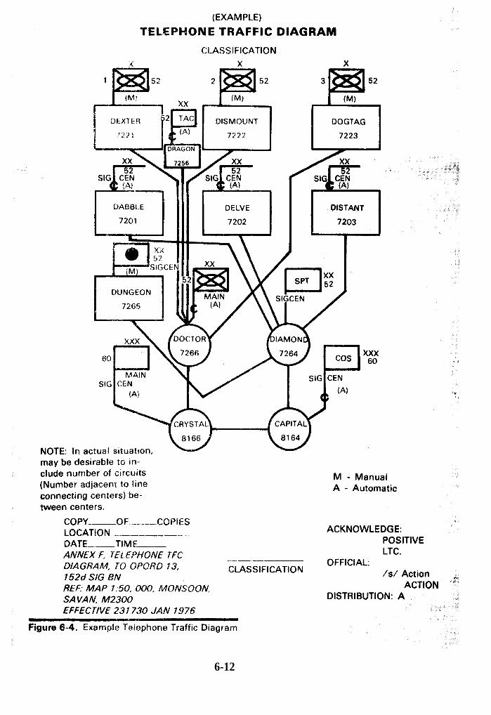
6-12

6-13

c. Distribution. Traffic diagrams are published in C-E operations orders,the C-E annex of the command operation order, or in a technical directiveissued by a CSCE. Simplified traffic diagrams are often published intelephone directories to assist subscribers in selecting call routes.d. Changes. Changes to traffic diagrams are required when units andnodes displace, when systems interface and routing changes, and whentraffic congestion occurs. The changes may be published as replacementpages or in a communications system document changeorder.
6-14

Note: Updating changes to traffic diagrams becomes essential as moresemiautomatic switches are introduced into the division area. Automaticswitches such as the SB-3614/TT (AN/TTC-41) require SL identificationswhen they are used in the division level system. Thus, SL’s must be includedon the traffic diagram to identify the switches. Fully manual switchboardsdo not require and are not assigned SL numbers unless they directlyinterface with a TAS (AN/TTC-38). Routing and PR-SL assignment in aTAS system are covered in FM 24-26.
6-9. Traffic Route Bulletin
A traffic route bulletin (table 6-3) is an extract from circuit and trafficdiagrams. It provides information on primary and alternatecommunications routes.a. In manual systems, the traffic route bulletin presents a tabular list of themajor unit headquarters and their subordinate commands served by othernodes of the communications network. The bulletin lists each unit, itscommunications designator or code name, and the primary and one or morealternate route(s) (designated by identifying intermediate nodes).b. In TAS networks, the traffic route bulletin may be used to designateprimary and alternate routes for the routing tables at each switch.6-10. Line Route Map
A line route map is used to specify and record the wire and cable routesin a communications system. In also pinpoints the locations of the facilitiesassociated with the lines. The line route map is keyed to a topographicmap(s) or map substitute and is usually prepared as an overlay (fig 6-6).a. Preparation. The C-E section of each major command prepares a lineroute map based upon the command’s wire and cable requirements.b. Input Information. When a signal construction unit installs a wire orcable system, it records any deviations from the specified wire or cablerouting on the line route map. This information, with reasons for anydeviations, is collected by the wire chief at the node responsible for theinstallation. The wire chief reports the changes to the CNCE(M) which, inturn, reports them in a communications document change order to thecontrolling CSCE. The CSCE data base is then updated to reflect the actualrouting. The CSCE data base should include—
(1) Map coordinates of termination points.(2) Locations of test points, repeaters, and other installed facilities.(3) Locations of link/circuit/channel identifications.(4) Points of interface with other systems.(5) Cable type, size, and special characteristics.
6-15
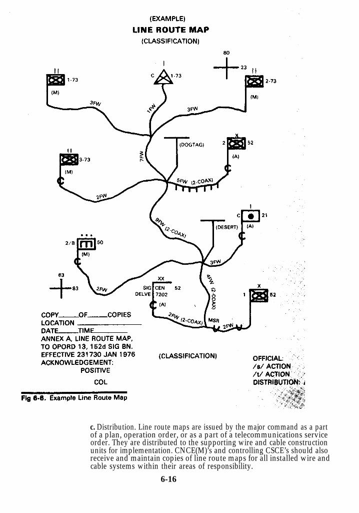
c. Distribution. Line route maps are issued by the major command as a partof a plan, operation order, or as a part of a telecommunications serviceorder. They are distributed to the supporting wire and cable constructionunits for implementation. CNCE(M)’s and controlling CSCE’s should alsoreceive and maintain copies of line route maps for all installed wire andcable systems within their areas of responsibility.
6-16

6-11. Multichannel Systems and Radio Net Diagrams
The multichannel systems and radio net diagrams contain the basicinformation necessary for the proper organization and operation ofmultichannel systems links and radio nets. The diagrams provide datarequired for frequency utilization and reduction of interference. They wayalso include information that specifies operating modes and conditions.
a. Multichannel Systems Diagram (fig 6-7). This diagram shows themultichannel system that supports a major command. Separate diagramsmay be used for area and for command multichannel links.
(1) The diagrams include:Locations and types of terminal radios, intermediate relays andoperating frequencies, cable systems.Antenna orientations (magnetic azimuths).Site elevations.Communications node locations at which multichannel groups areto be determined.
(2) Preparation. The C-E section of a major command and the seniorsignal unit prepare multichannel systems diagrams during theplanning phase. The preparation procedure is shown in figure 6-8.
(3) Input Information. In preparing the multichannel systemsdiagram, the C-E section obtains information from the CSCE databaseconcerning the network layout (equipment, operation, frequency,antenna azimuth data, etc.). The CSCE data base should be the mostreliable source of information because it is continuously updated bychange information from the CNCE(M)’s.(4) Distribution. Normally, multichannel systems diagrams are issuedas a part of the C-E annex to the command operations order.(5) Changes. Changes to multichannel systems diagrams may beissued as replacement pages to the C-E annex or as bulletins in thecommunications system document change order format.
b. Radio Net Diagrams (fig 6-9). The types of radio nets for the army in thefield are dictated by the tactical requirements for each using organization.Variations of the basic (standard) nets may be required because of unitmissions, tactical resources, and available resources.
(1) Preparation (fig 6-10). The C-E staff of each major commandprepares the radio net diagrams which are normally command orientedand supplement the multichannel systems. The senior signal unit andeach organic subordinate unit prepare radio net diagrams which areforwarded to the command C-E section.(2) Input Information. The senior signal unit obtains information fromthe CSCE data base on frequencies, call signs, and net composition.Frequencies and call signs are also listed in the CEOI.(3) Distribution. Radio net diagrams are normally issued as a part ofthe C-E annex to the command operation order.(4) Changes. Changes to radio net diagrams may be issued asreplacement pages to the C-E annex or as bulletins in thecommunications system document change order format.
6-17

6-18

6-19
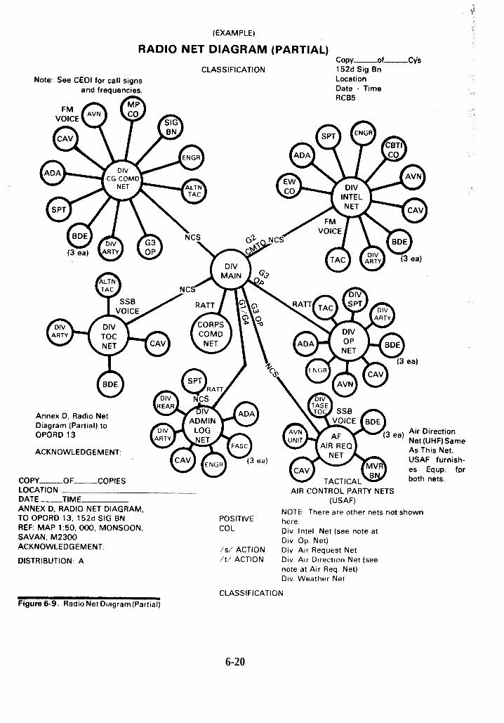
6-20
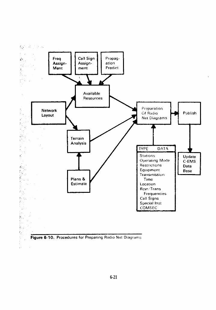
6-21

6-12. System Performance Analysis
System performance analysis (fig 6-11) is the process of collectingperformance data, identifying effectiveness indicators, and evaluating theindicators to determine communications system effectiveness in meetingrequired standards. The primary objective of the analysis is to determinewhat actions, if any, can be taken to improve system performance.
a. Collection of Performance Data. Data is collected continuously atCSCE’s based on operational reports and records; this permits frequentsystem performance analysis.
b. Performance Indicators. Indicators may be extracted directly from theraw data collected or they may be obtained after data reduction ormanipulation. The performance indicators may vary with commands andnetworks, depending upon mission requirements, established standards,command interests, etc. Examples of performance indicators are:
Grade of service.Speed of service–by precedence.In-station handling times–by precedence.Station/area outages.Circuit outages.Spare resources employment.Control measures–by type.Security violations.
c. Analysis and Comparison. Performance indicators must be analyzed,along with the plans and directives that affect performance and operatingcapabilities, and then compared with established standards to develop themeasures of system effectiveness. The standards for comparison will varywith networks and commands, depending upon available equipment,personnel, and the personnel training status. When applicable to thetactical networks, appropriate DOD and DCS performance standardspertaining to systems interface will apply.
d. Measures of System Effectiveness. The measures of system effectivenessmay be in either quantitative or qualitative terms. They are used as a basisfor determining corrective actions, as factors in estimates and plans forfuture operations, and as input data for submission to the Department of theArmy.
e. Responsibilities. Each major command is responsible for analyzing thecommunications system performance for its area of communicationsresponsibility y through its CSPE\CSCE. Within a theater of operations,system performance analysis should be performed as frequently asnecessary to insure compliance with prescribed system standards andperformance criteria.
6-22

(1) The commander of the senior signal organization supporting amajor command is responsible for periodically conducting an analysisthat is responsive to prescribed mission objectives and operationalstandards prescribed by the command C-E staff. The C-E staff willreview the measures of effectiveness that are developed by the signalcommander for objectivity and mission accomplishment.(2) The corps C-E section will consolidate the division and corpsanalyses. The theater army and corps analyses will form the basis ofthe system performance information provided to the Department of theArmy tailored to fit CONUS needs.
6-23
6-13. Electronic Counter-Countermeasures (ECCM)
ECCM is the function of insuring that all measures are taken to countersurveillance and maintain continuity of communications services in thepresence of enemy electronic countermeasures (ECM). The primaryobjectives of C-EMS operations related to ECCM are the reporting ofsuspected ECM activities (i. e., deception and jamming) as expeditiously aspossible and the prompt restoral of degraded communications.a. ECCM Procedures. The following methods are used to accomplish ECCMfunctions:
(1) Engineering the network layouts to minimize both the surveillanceof the system and the traffic that passes over the networks.(2) Implementing operating techniques to improve overall networkperformance in the presence of enemy jamming. Such techniquesinclude changes in antenna orientation, application of specialmodulation schemes and information transfer rates, changes of RFemission power, applications of special circuits, and switching toalternate frequencies.(3) Modifying the network layout to reduce interference resulting fromenemy jamming.(4) Operation of special communications stations and nets and/orpassing of dummy traffic to deceive enemy surveillance efforts.
b. ECCM Responsibilities. Overall coordination of the ECCM function forthe Army in the field is the responsibility of the theater army C-E section.The corps C-E section is delegated the authority by the theater army, toconsolidate ECCM information within the combat zone. The consolidatedinformation is then forwarded to theater army headquarters.
6-24

C h a p t e r 77-1. Introduction
The C-EMS control functions providedirection for the use and operation ofcommunications facilities, and directlyaffect the total C-E system. The CSCE and CNCE control functions discussed herecomplement those of the CSPE and providedirection for the CESE.7-2. Communications System Control Element (CSCE)
At the higher echelons of command, the communications systemcontrol element (replaces SYSCON) is the information and direction centerfor all subordinate C-E systems. The CSCE maintains the data base forinformation needed to upgrade, modify, and manage the C-E systems. Thisdata base may be in the form of manual reports or computer stored data. TheCSCE functions are oriented toward near real-time management andcontrol and are designed to assure the best performance of the C-E system.The CSCE prepares orders to implement CSPE planning and engineering,performs short-term traffic engineering, makes adjustments in systemconfiguration, and resolves day-to-day troubles and system problems. Thefunctions of the CSCE include the following.a. Implementation and installation. Prepares installation orders tosubordinate elements (CNCE) which will implement CSPEplanning/engineering actions for:
Installation, restoration actions, and priorities.General site locations.Radio antenna orientation.Quantity and distribution of essential access and trunking circuits.Modifications to communications links.Interface facilities.Switching, store and forward, and trunking equipment.
b. Monitoring. Maintains, analyzes, and displays system statusinformation, including:
Traffic data.System and equipment performance data.Equipment restoral status.Grade of service.Outages and backlog situations.
c. Traffic control management. Assures effective customer service throughcontrol measures such as:
Routing changes.Trunk barrings.Line load controls (minimize).Trunk and link directions.Control of queues.
7-1
d. Transmission system routing control. Insures best use of resourcesthrough:
Reallocation of satellite and airborne radio relay channels.Allocation of dedicated circuits.Internodal routings.Determination of number and distribution of trunking circuits.Restoration priorities.
e. Reporting. Assembles staff guidance for the commander.(1) This function, fundamental to efficient C-EMS operations, stemsfrom the requirement to obtain timely and accurate information fromthe nodes within the network. The data should be provided by means ofperiodic standardized reports that can be prepared with the minimumexpenditure of manpower resources. The information in the reports willbe used as the basis for performing other C-EMS functions, as well asfor providing inputs to data bases maintained by various elements inthe C-EMS management structure.(2) The CNCE(M) is responsible for direction and control of reportingat a communications node and should specify in an SOP the format andprocedures to be used. The CNCE(M) should originate all reports fromthe node. Within the node, verbal reporting should be the principalmeans for transferring C-EMS information (written reports beingused only when essential for record purposes). For reports outside thenode, teletypewriter facilities are normally used, supplemented asnecessary by verbal information. The CNCE(M) selects the methodand channels used for the transmission of reports. Also, the CNCE(M)determines the necessity for information copies of reports to higherheadquarters not in the direct channel for report transmission.(3) The CNCE(M) collects incoming status reports on installation,equipment, personnel, traffic volume, system and circuit quality, andother related data. It also prepares outgoing status reports on systemand circuit quality, fault-correction actions, equipment status, andsystem and circuit installation or deactivation. In addition, it preparesreports on internodal routing, rerouting, and restorals; and updatesinformation for the CSPE and other reports as required.
f. Records keeping. Initiates, maintains, and retains the informationwhich comprises the C-E data base.g. Management of COMSEC resources, including keying material. Thisfunction is programed for the CY 1980 time frame.h. Directory control. This function includes the updating and publicationof directories, routing guides, etc.
7-3. Communications Nodal Control Element (CNCE)
The control element at its lowest functional level, usually company, isdivided into two operational sections: the communications nodal controlelement (management) (CNCE(M)) and the communications nodal controlelement (technical) (CNCE(T)).a. The CNCE(M) is the direct arm of the commander and replaces thefacilities control function. The CNCE(M) is primarily responsible forrecords and reports, accounting, coordination of communicationsrequirements, and management of the communications equipment supportelements (CESE).
7-2

b. The CNCE(T) has direct control over circuitry and replaces the technicalcontrol function. It has all the required resources to perform technicalsupervision of communications media and equipment, to restore lost ordegraded services, to accomplish continual quality assurance of installedcircuitry, and to initiate new services on receipt of proper orders (TSO). Italso provides technical information to the CNCE(M) for records and reportsconcerning the installed circuits and systems.
c. For maximum efficiency, the CNCE(M) and CNCE(T) are co-located.When these elements are not co-located, the problems encountered incoordination, transfer of information, and response materially degrade theoverall C-E system.
d. The CNCE functions include:(1) Management and technical direction. Exercises management andtechnical direction over subordinate activities and CNCE’s.(2) Implementation and execution. Responds to directives from thecontrolling CSCE.(3) Line circuit conditioning and interfacing with C-E systems.Provides equipment necessary to condition analog and digitalcircuits for best performance.
(4)
(5)
(6)
(7)
Provides interface for direct current (dc) circuits, voice frequency(vf) circuits, dc-to-vf conversion, and analog-to-digital conversion,etc.Activation and deactivation of circuitry.Complies with CSCE orders.Directs subordinate activities and subscribers to execute orders.Coordinates with other CNCE’s.Monitors circuit activation and deactivation.Technical coordination to accomplish quality assurance programs.Modifies or corrects circuit configuration and coordinates changeswith CSCE.Tests installations of subordinate CESE’s for adherence toestablished standards.Maintenance of systems standards.Conducts in-service and out-of-service quality control throughperformance monitoring and testing.Conducts fault isolation on intranodal, internodal, and extensionfacilities (DCS, allied, commercial transmission systems).Refers fault isolation findings and corrective actions to appropriatesubordinate activities.Rerouting and restoration of circuits, groups, and systems; updates
nodal records to reflect all changes.(8) Reports and reporting.
Receives reports and takes the necessary action in the areas ofactivation and deactivation (TSO), resource commitments, troubleconditions, performance data, test results, and facility status.Sends reports to controlling CSCE and to appropriate subordinate
7-3

CESE’s concerning activations and deactivations, trouble status,coordination with other CNCE’s(T), equipment status,performance data, testing data, and system status.
(9) Records keeping. Records are maintained for the currentdeployment as opposed to the comprehensive data base maintained bythe CSCE. The records include:
Circuit records with orders and technical directives regardingcircuit connectivity (TSO), electrical and physical connections atthe CNCE nodal facilities for which it is technically responsible,and the availability of circuits and equipment at the node arenecessary for real-time operation.System and circuit status records of all systems and circuitsterminating at the node.Nodal data base update (directories, etc.).
e. The CNCE(M) implements restrictive measures when traffic overloadsthe system. This involves the restriction of communications service tosubscribers on a selective or priority basis to reduce originating traffic forcertain areas. The C-E staff of each major command prepares, for thecommander’s approval, the broad policies for accomplishing the following:
(1) Trunk barring. This measure denies subscriber access to specifiedtrunk groups. The operator at the affected node will no longer serviceoutgoing calls on the designated trunks (manual system).(2) Minimize. This administrative measure is employed to restrictselected users from the telecommunications system. A directive fromthe senior commander states the restrictive conditions and subscribersauthorized to initiate trunk calls during periods of MINIMIZE.(3) Line load control. This is a feature of automatic switches which,when activated, permits subscribers to make local calls only. Outgoingtrunk calls are prohibited; incoming trunk calls are allowed.
f. At some staff and unit levels, implementing restrictive measures requiresa planning and engineering effort. At most operating unit levels, thefunction is primarily a control measure that is applied at the switchingcentral or at the telecommunications center where message trafficis originated. Each controlling CSCE should be delegated the responsibilityof trunk barring and line load control within its area of responsibilityconsistent with established policies and procedures.g. With tactical automatic telephone switches, certain features permit database changes that provide a means of selectively limiting communicationscapabilities. Some of the restrictive measures available with the automatictelephone switches are line load control, changing class of service marks,and cancellation of alternate routing. Also, the switches contain a reroutingmatrix that will permit rerouting of traffic in the event a distant nodesustains degradation or traffic overload problems. In some switches, this isaccomplished by automatic alternate routing; in others, it must be done bymanually changing the routing in the data base.h. The CNCE(M) establishes authentication procedures to protectinformation. These procedures will be necessary until totalcommunications security is achieved. Until then, a need exists to enforceauthentication procedures used for transmissions on unsecured channels.These procedures are designed to minimize enemy deception. Theprocedures establish who authenticates; when to authenticate; and how toauthenticate. Authentication policy is developed by the Department of theArmy. Army publications, AR 380-52 and DA Pam 380-150, interpret the
7-4

instructions and provide procedures for use throughout the Army.Authentication tables are generated only by the National Security Agency(NSA) and are available through COMSEC logistics channels. AR 710-2addresses COMSEC logistics and describes procedures for request anddelivery of authentication tables to major commands.i. Both the CNCE(M) and CNCE(T) participate in restoring circuitry thathas become substandard. This function assures the return ofcommunications service to acceptable standards after communicationsfailure or degradation. Participants in restoration actions are at all levels ofauthority and responsibility, depending on the extent of the damage andthe decision level required to accomplish the recovery. Although one unitmay be specifically charged with establishing and maintaining signalcommunications with another, both units are responsible for takingimmediate action to restore disrupted communications. Restoration ofservice is the responsibility of the lowest level CSCE in the C-EMSorganization that has control of all nodes affected by the trouble.
(1) Restoration starts when a trouble report is received from a nodefacility, remote CNCE(T), or CSCE. The CNCE(M) initiates therequired actions and coordinates with, adjacent or remote nodes. EachCNCE(M) has the responsibility for restoration actions affecting itsnodes, consistent with system priorities and requirements. For rapidrestoration of service, the CSCE provides traffic engineering support asrequired to the CNCE’s(M).(2) The TAS system is preengineered to restore or reroute servicethrough the use of information stored in a data base. For example, inthe AN/TTC-38 automatic telephone central office, prepunchedrouting tapes may be used to change the routing around a damagednode. Future devices will use memory storage to accomplish the sameaction.(3) Facility damage requires the submission of a trouble report to theCSCE by the CNCE(M). Damage may be total, such as the completedestruction of a multichannel relay or multiplex terminal; or damagemay be partial, such as the loss of a major component of a terminal(power unit, spare transmitter, distribution cable), or antenna damagethat produces a link degradation.(4) When a facility is partially damaged, available spare componentsare placed in use, pending repair or replacement of the damaged items.This is accomplished at the direction of the CNCE(M). However, ifdamage is total, a reserve facility must be activated (as approved by theCSCE). Simultaneously, backup service will be initiated. Additionalmessenger service will be provided and, if needed, RATT which isnormally used for control purposes will pass traffic to adjacent nodes. Ifjamming or interference is involved, total loss of the link might wellnecessitate a frequency change, as directed by the CSCE or asauthorized in the CEOI.
j. Jamming or interference could produce complete loss of linktransmission or degradation. The remedies for those problems areessentially the same as those for reported damage and could be included incontingency plans. For example, telephone, teletypewriter, or data trafficwould be promptly rerouted. This could involve circuit patching by theCNCE(T) to bypass the affected node or to provide alternate routes and thetransmission of teletypewriter traffic by way of alternate tape relays to andfrom the affected node. In the case of enemy jamming, antijammingtechniques are attempted first. If available, a reserve facility might beplaced into operation on a new frequency while continuing operation on thejammed frequency.
7-5

k. The CNCE(T) physically performs all patching in the control facility atthe node. Patching is the installation of permanent or semipermanentconnections in order to route circuits between node facilities and accesspoints in a communications system or to redistribute them within a node.Patching may be performed to activate or deactivate service, to implement arestoration plan, or to modify the configuration of a communicationssystem in accordance with changes in traffic loading. Patching can alsoroute a multichannel group directly through a node as part of a trafficengineering plan to bypass a damaged portion of the system. Patching isperformed by a CNCE(T). There must be close coordination throughout theimplementation process. When a system is engineered, it should bedesigned so that most circuits are “normal-through” where possible.Patching is performed by a CNCE(T).
(1) When patches are made on a system involving two or more nodes,the requirements are determined by the CSCE performing trafficengineering of the system. The controlling CSCE must initiate thenecessary plan and coordinate its implementation through CNCE's(M)at the nodes. Coordination of system patching will be done as necessarybetween CNCE’s(T) at terminal and relay points. Senior signal unitCSCE’s are responsible for maintaining a record of all internodalcircuit and group patching that they have ordered at nodes within theirarea of responsibility using the communications control journal (DDForm 1753) and TSO’s.(2) The CSCE’s should delegate to nodal commanders the authority tochange circuit patches on extension systems installed and operated bythe nodal commanders. In addition, CNCE(T) may make circuitchanges within a node when they do not affect system capabilities. TheCNCE(T) will maintain, on a current basis, a system and circuit recordof all patching accomplished at the node.
l. The CNCE(T) tests all circuits and systems according to a scheduledictated by the CNCE(M). Testing is performed on circuits to insure thatthey meet performance standards prior to implementation of service.Testing is also performed to identify the source of a disruption of service(fault location), to ascertain the extent of damage or degradation, and toverify that required standards of service are being provided afterrestoration.
(1) The testing process can be initiated as the result of monitoring, thereceipt of a trouble report, or by direction of the CNCE(M), based upon arequest that originated from outside the node. Facility operatingpersonnel (CESE) will perform testing by using either the auxiliary testequipment or the testing capabilities designed into the system. In somecases, test equipment located in facilities other than the CNCE(T) maybe used. Authorization for the use of those facilities is arranged throughthe CNCE(M).(2) The testing of circuits is performed according to establishedprocedures. Some circuits may be tested while they are in use. All usersof these circuits MUST BE NOTIFIED PRIOR TO TESTING. Othersmust be tested when not in use to prevent the false triggering of alarmcircuits within the equipment. In all testing of circuits involving theTAS, the circuit controller in the CNCE(T) must coordinate with theTAS personnel prior to testing. Failed circuits are retested as soon aspossible. Restoration is based upon the priority rating of that circuit.of that circuit.(3) All test operations related to internodal circuits are monitored andcoordinated by the circuit controller at the CNCE(T). The installationand maintenance personnel assigned to a node should be directly
7-6
responsible for the testing and maintenance of the intranodalcommunications system.(4) The CNCE(T) should record the results of testing received fromoperating facilities (CESE) or other CNCE’s(T) on a system and circuitstatus record.(5) The CNCE(T) will report the test results to the CNCE(M), which inturn may report to the CSCE. For significant outages, reports may berendered up through the entire communications chain. For lessertroubles, such as a single (nondedicated) channel or a local telephoneproblem, reports are generally limited within the node. However, theCNCE(T) of the node should be informed promptly of any testing withinthe node that is related to actual outages or trends toward interruptionof service.
m. The CNCE(T) monitors circuits on a continual basis. This function is forthe purpose of observing the performance of communications facilities inorder to detect indicators of inadequate performance or to detect trendsleading to degradation in performance. Monitoring, an inherent element offacility operation, can be accomplished as prescribed by SOP, as directed, orduring performance of preventive maintenance. The function involvesobservation by operating personnel or by automatic metering, alarms, ormonitoring devices built into facility equipment and auxiliary devices.
(1) All operating facilities of a node are monitored, includingmultichannel transmission terminals and relays, multichannel radioand cable extension links, multiplex equipment, automatic telephoneswitches, and the teletypewriter/data facilities of the terminal and thetape relay sections. When monitoring of TAS circuits could result intriggering of alarm circuits, TAS personnel must be notified.(2) The CNCE(M) has overall responsibility for the properaccomplishment of monitoring at a node and should provideappropriate SOP guidance for the operating facilities.(3) The CNCE(T) is responsible to the CNCE(M) for monitoring theperformance of all internodal circuits. The CNCE(T) maintains asystem and circuit status record. This record shows the status ofsystems and circuits terminating at the node. The CNCE(T) will relymainly on operating facility personnel (CESE) to report any noted linkor equipment outages or degradation. Monitoring results are reportedby operating personnel to the CNCE(T) as required by local proceduresor as directed by the CNCE(M). The CNCE(T) reports to the CNCE(M)which, in turn, may relay the information in the appropriate format to aCSCE. However, all monitoring results should not necessarily bereported outside the node. The CNCE(M) makes the decision as to whenmonitoring results will be reported to the controlling CSCE.
7-4. C-E System Deactivation
a. The following establishes guidelines for commanders when closingdown a system. The primary objective is to insure that everyone involved isproperly notified of closure time, procedures, actions, and directions tofollow before, during, and after the closure. There are two methods ofnotification: normal chain of command channels and technical controlchannels.b. Overall responsibility for closure rests upon the commander of thesystem. He delegates this responsibility downward, through both the chainof command and the technical control channels (C-EMS), to rest finallywith the CSCE and CNCE’s directly involved in the deactivation of thesystem.
7-7

c. The closing of a C-E system, or any portion of it, is a control procedureand requires close coordination between all elements of that system. Pastexperience shows that the process of closing a C-E system can vary from asmooth operation to a gigantic “snafu.” The experience level of thepersonnel controlling and operating the systems is a critical element; andbecause experience varies from person to person, a precise method of controlis required.d. Closure orders which include the activities involved, closure times, andactions to be followed after the closure are sent to the CSCE and CNCE’s.Both command and technical control channels are used to insure thateveryone involved “gets the message.”
SECURITY NOTE: All orders or instructions relative to closingdown the C-E system must be authenticated according to instructionsprovided by the CEOI. This requirement applies regardless of how theinstructions or orders are issued.e. The CSCE, acting through the controlling CNCE, directs and supervisesthe closing of the system. The CNCE, in turn, notifies all subscribers of theclosure time. Normal chains of command, engineering orderwire, and otherengineering channels are used to notify all systems, relays, andsubscribers, including users of “strap-through” and “dedicated” (sole-user)circuits.f. When closure time occurs, the CSCE/CNCE’s direct subordinate units toterminate subscriber service. The CNCE verifies termination of allsubscriber service and notifies the CSCE. The activation/deactivationreports may be used to conclude this action; if the situation permits orwarrants it, however, verbal notification will suffice.g. After the CSCE receives verification of subscriber termination, theCSCE notifies the controlling CNCE to begin closing down the trunkingsystem. The CNCE then directs operating personnel of the terminalequipment (carrier, multiplex, or radio) to notify all relays and terminals inthe system to close down. Each one closes, in turn, beginning with the mostdistant point, thus assuring that all units in the system are notified of theaction to close and, in fact, do close.h. After receiving verification that the entire system has closed, the CNCEfiles an activation/deactivation report with the CSCE and then closesdown. The CSCE, at this point, records the time of closure and reports tohigher headquarters that the system is closed, and any communicationrequired is over single channel radio nets.
7-8

A p p e n d i x A
Department of Defense (DOD) Regulation
(C) 4605.25200.1-R Information Security Program Regulation
Department of the Army Regulation
310-20 Military Publications—Allied CommunicationsPublications (ACP) and Joint Army, Navy, AirForce Publications (JANAP)
Department of the Army Pamphlets (DA Pam)
310-1 Military Publications—Index of AdministrativePublications (Regulations, Circulars,Pamphlets, Posters, JCS Publications, andGeneral Orders)
310-2 Military Publications—Index of Blank Forms310-3 Military Publications—Index of Doctrinal, Train-
ing and Organizational Publications (FieldManuals, ROTC Manuals, Training Circulars,Army Training Programs, Army SubjectSchedules, Army Training Tests, Firing Tablesand Trajectory Charts, Tables of Organizationand Equipment, Type Tables of Distributionand Tables of Allowance)
310-4
(O) 310-9
Military Publications—Index of TechnicalManuals, Technical Bulletins, Supply Manuals(Types 7,8, and 9), Supply Bulletins and Lubrica-tion Orders
Index of Communications Security (COMSEC)Publications (U)
A-1
A p p e n d i x B
B-1. Tactical Telephone Numbering Plan (TTNP)The introduction of automatic switching into the tactical
communications-electronics system requires a new approach to thetelephone numbering scheme. The plan presented in this appendix has beenmodified based on user comments and experience gained through the use ofautomatic switches AN/TTC-25 and AN/TTC-38.a. This plan was developed following the guidelines provided in MIL-STD-188C, 24 November 1964, and is a primary zone (PR) switch locator (SL)oriented system. It has widespread impact on areas other than automaticswitching, because of the limited number of automatic switches in thecurrent inventory and the number of manual switches with which it mustpermit interface in the automatic voice network (AUTOVON), as well as C-E systems engineering considerations.b. The plan, as presented, provides the basis for future numbering planswhich must be devised to function within the scope of equipment underdevelopment; e.g., AN/TTC-39, SB-3614/TT, and unit level switches (ULS).These are expected to be fielded in the 1980’s. Furthermore, the systemevolving (from practical experience) must take into consideration therequirements of INTACS, EAD, and the TRI-TAC systems of the future.Factors to be considered include: proposals by allied/NATO forces for a 13-digit system, the capability of the AN/TTC-39 to provide 10 digits fromAN/TTC-39 to AN/TTC-39; the existing 13-digit Allied/NATO elementssystem; and seven digits down to the level of the AN/TTC-38’s, SB-3614/TT's, and ULS’s. Finally, under TRI-TAC, the entire theater ofoperation must eventually use a system that is common to Army, Navy, AirForce, Marines, and DCS.c. The tactical telephone numbering plan (TTNP) provides for theassignment of PR’s by geographic location, thereby allowing each PR toserve a maximum of 100 (00-99) switch locations (SL’s). Geographic areasrequiring more SL’s than are provided may be assigned additional PR’s, asrequired. PR assignment is the responsibility of the theatercommunications system planning element (CSPE). Restriction of PRassignment is limited to a single PR. 99; it is used only for providingsubscriber access to the fixed directory system inherent in the TTNP.
B-1
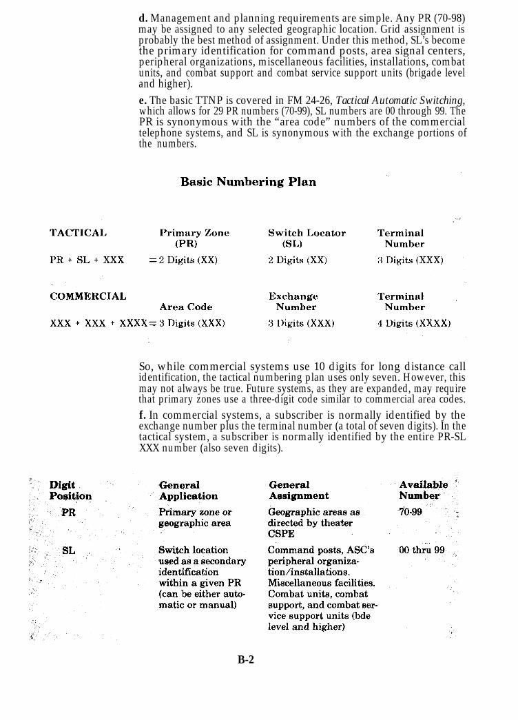
d. Management and planning requirements are simple. Any PR (70-98)may be assigned to any selected geographic location. Grid assignment isprobably the best method of assignment. Under this method, SL’s becomethe primary identification for command posts, area signal centers,peripheral organizations, miscellaneous facilities, installations, combatunits, and combat support and combat service support units (brigade leveland higher).e. The basic TTNP is covered in FM 24-26, Tactical Automatic Switching,which allows for 29 PR numbers (70-99), SL numbers are 00 through 99. ThePR is synonymous with the “area code” numbers of the commercialtelephone systems, and SL is synonymous with the exchange portions ofthe numbers.
So, while commercial systems use 10 digits for long distance callidentification, the tactical numbering plan uses only seven. However, thismay not always be true. Future systems, as they are expanded, may requirethat primary zones use a three-digit code similar to commercial area codes.f. In commercial systems, a subscriber is normally identified by theexchange number plus the terminal number (a total of seven digits). In thetactical system, a subscriber is normally identified by the entire PR-SLXXX number (also seven digits).
B-2

B-2. System Designation and Circuit Identification
Both system designation and circuit identification numbering schemeswill eventually be standardized worldwide. The plan presented here,however, is intended to allow the flexibility for future systems that may
telephone numbering plan orrequire either an expanded tacticalsystem/circuit identification system.
This system designation and circuit identification plan allows thetheater planning element to assign site (node) numbers to each unit with thetheater. Future application of system and circuit identification may requirethat the origin and destination be indicated using the PR-SL. This iscurrently being considered as part of the data base requirements for thetactical communications control facilities (TCCF). Space availability in theTCCF computer is presently established for 7, 9, and 11 character bits to beused for circuit and system identification numbers.
As development of future equipment is completed, development of acompatible and complementary numbering system to match thatequipment must also be accomplished. The current plan allows for thatexpansion. Further, the plan uses the DOD method of priority designationin both systems and circuits and it is used on the circuit routing list (CRL).B-3. System Designators
The system designator consists of seven characters. This numberidentifies the origin and destination of the system and the type of system.a. The originating terminal is the control terminal for installation andrestoral purposes.
b. Each signal site (node) has a designator consisting of either two or threecharacters. These site designators are assigned in accordance withguidance established by the theater army C-E staff. (For the purposes ofdiscussing the numbering plan in this appendix, USAREUR sitedesignators are used as examples.) The theater CSPE (or responsibleplanning element) must assign identifying digits to all units andpromulgate this as a part of the C-E SOP. At division level and higher, eachmajor command is assigned a unique letter designator as the first characterof its site designator. This provides the advantage of identifying anyterminal site having a first letter designator of “R”, for example, as a 3dInfantry Division unit. The second digit then identifies the specific site.
B-3

(1) First characters of two-digit site designators:
A:B:C:D:E:J:P:R:S:U:V:
7th Signal Brigade11th Armored Cavalry Regiment32d Army Air Defense Command1st Infantry Division1st Armored DivisionVII Corps8th Infantry Division3d Infantry Division3d Armored DivisionUSAREUR/7th ArmyV Corps
(2) Second characters of two-digit site designators:
1:2:3:4:5:
6:7:8:9:0:
A-F:Y, Z:
G:J, K, L:
M:N:P:R:S:
Signal MainSignal AlternateArtillery BattalionArtillery GroupArmored Cavalry RegimentSupport CommandEngineer BrigadeAviation BattalionSpareBaseMain/TOC LocationsTac/Alt/Fwd CP LocationsADA GroupDemods1st Brigade2d Brigade3d Brigade4th Brigade/Separate Brigade5th Brigade/Separate Brigade
c. Site designators of terminals within the COMMZ will consist of twonumerical characters, assigned as follows:
00-49: Army area signal centers50-69: USAREUR subordinate units within
COMMZ
B-4

70-79:97:
80-96, 98-99:
Theater army signal battalionsCENTAGSpares, assigned to corps/divisionunits
(1) Character 5 indicates system type:C - Cable with PCM multiplexH - HF multichannelK - Satellite multichannelM - Microwave radio with PCM multiplexP - UHF radio with PCM multiplexT - Troposcatter radio with PCM multiplexU - Mixed system with PCM multiplexV - UHF radio with FDM multiplexNOTE: Future systems may require additional letterdesignator(s) for new system types.
(2) Character 6 indicates identical systems between two systemterminals:
A - 1B - 2C - 3D - 4E - 5F - 6G - 7H - 8
(3) Character 7 identifies the 12-channel group number (and shows thenumber of channels):
A - 1st 12-channel groupB - 2C - 3D - 4E - 5F - 6G - 7H - 8
B-5
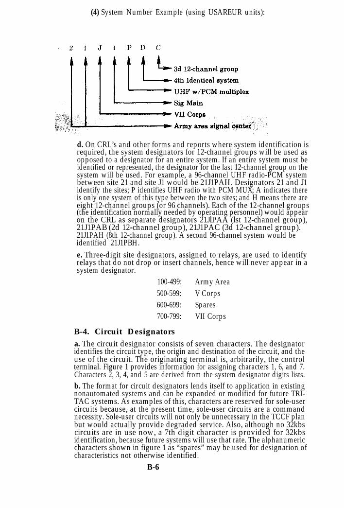
(4) System Number Example (using USAREUR units):
d. On CRL’s and other forms and reports where system identification isrequired, the system designators for 12-channel groups will be used asopposed to a designator for an entire system. If an entire system must beidentified or represented, the designator for the last 12-channel group on thesystem will be used. For example, a 96-channel UHF radio-PCM systembetween site 21 and site J1 would be 21J1PAH. Designators 21 and J1identify the sites; P identifies UHF radio with PCM MUX; A indicates thereis only one system of this type between the two sites; and H means there areeight 12-channel groups (or 96 channels). Each of the 12-channel groups(the identification normally needed by operating personnel) would appearon the CRL as separate designators 21JlPAA (lst 12-channel group),21J1PAB (2d 12-channel group), 21J1PAC (3d 12-channel group).21J1PAH (8th 12-channel group). A second 96-channel system would beidentified 21J1PBH.e. Three-digit site designators, assigned to relays, are used to identifyrelays that do not drop or insert channels, hence will never appear in asystem designator.
100-499: Army Area500-599: V Corps600-699: Spares700-799: VII Corps
B-4. Circuit Designatorsa. The circuit designator consists of seven characters. The designatoridentifies the circuit type, the origin and destination of the circuit, and theuse of the circuit. The originating terminal is, arbitrarily, the controlterminal. Figure 1 provides information for assigning characters 1, 6, and 7.Characters 2, 3, 4, and 5 are derived from the system designator digits lists.b. The format for circuit designators lends itself to application in existingnonautomated systems and can be expanded or modified for future TRI-TAC systems. As examples of this, characters are reserved for sole-usercircuits because, at the present time, sole-user circuits are a commandnecessity. Sole-user circuits will not only be unnecessary in the TCCF planbut would actually provide degraded service. Also, although no 32kbscircuits are in use now, a 7th digit character is provided for 32kbsidentification, because future systems will use that rate. The alphanumericcharacters shown in figure 1 as “spares” may be used for designation ofcharacteristics not otherwise identified.
B-6
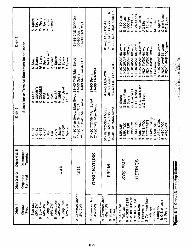

c. The following examples illustrate the flexibility of this circuitnumbering plan.
EXAMPLE 1. A common-user (4W-4W) telephone trunk from 8th InfMain TTC-41 to TTC-38 at V Corps COSCOM (control terminal).
*61 indicates that this is the first circuit of this type betweenthese points.
EXAMPLE 2. A sole-user (2W-2W) telephone circuit from 1st Bde, 3dInf Div Cdr to G3, 3d Inf Div (control terminal).
EXAMPLE 3. A common-user teletypewriter circuit (FDX Crypto4WVF 100 WPM) from TADS at the army area signal center(designated 36) to the 32d AADC Main CP (control terminal)telecommunications center.
B-8

EXAMPLE 4. A facsimile circuit from 3d Armored Division AviationBattalion to USAREUR/7th Army Main (control terminal).
Note: When the character indicating “other” is used, explanation canbe made on CRL. When the new family of digital facsimile equipment isfielded, additional identifiers (characters) will be made (using spares) toprovide essential circuit information.d. Using this format as shown in the examples, an operator or technicalcontroller can readily tell the difference between telephone service circuitsand digital service circuits by the first digit of the circuit number. Alltelephone circuits have a numerical digit as the first character; all digitalservice circuits (teletypewriter, data, etc.) have an alpha digit as the firstcharacter.e. When multiple, identical digital service exists between two points, thespare digits available for the 6th digit can be used to identify the individualcircuits. For instance, four teletypewriter circuits installed between twomanual relays could be identified as GXXXX1C, GXXXXJC, GXXXXKC,and GXXXXLC, noting that here the spare digits J, K, and L are used. Whenspare digits are to be used, the theater CSPE should prescribe their usebased on the theater need for multiple circuits between points.
B-5. Priorities for System and Circuit Restoral
a. Each system and circuit in the C-E network is assigned an alphanumericpriority indicator dictating its installation sequence and restoral priority.This number, consisting of two characters, appears in the priority indicator(PRI) column of the circuit routing list (CRL). System planners andengineers are responsible for assigning circuit and system priorities andshould include the priority assignments in the CRL.
(1) System Priority–The priority of any system will be the same as thehighest priority circuit on that system (excepting control circuits). Anabsolute chronological order for system restoration is unnecessary. TheCSPE must insure that backup circuits are not assigned to the samesystem as primary circuits to provide uninterrupted communications.(2) Circuit Priority–The priority of a circuit is established andassigned by the planning/engineering element, based on guidelinesestablished in DOD Directive 4605.2 (Confidential).
B-9
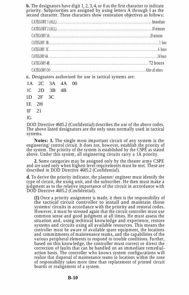
b. The designators have digit 1, 2, 3, 4, or 0 as the first character to indicatepriority. Subpriorities are assigned by using letters A through I as thesecond character. These characters show restoration objectives as follows:
c.
CATEGORY 1 (ALL) . . . . . . . . . . . . . . . . . . . . . . . . . . . . . . . . . . . . . . . . . . . . . . . . . . . . . . . . . . . . . . . . . . ImmediateCATEGORY 2 (ALL) . . . . . . . . . . . . . . . . . . . . . . . . . . . . . . . . . . . . . . . . . . . . . . . . . . . . . . . . . . . . . . . . . . 10 minutesCATEGORY 3A . . . . . . . . . . . . . . . . . . . . . . . . . . . . . . . . . . . . . . . . . . . . . . . . . . . . . . . . . . . . . . . . . . . . . . . . . . . . . . 20 minutesCATEGORY 3B . . . . . . . . . . . . . . . . . . . . . . . . . . . . . . . . . . . . . . . . . . . . . . . . . . . . . . . . . . . . . . . . . . . . . . . . . . . . . . . . . . . . . . . . 1 hourCATEGORY 3C . . . . . . . . . . . . . . . . . . . . . . . . . . . . . . . . . . . . . . . . . . . . . . . . . . . . . . . . . . . . . . . . . . . . . . . . . . . . . . . . . . . . . . 6 hoursCATEGORY 4A . . . . . . . . . . . . . . . . . . . . . . . . . . . . . . . . . . . . . . . . . . . . . . . . . . . . . . . . . . . . . . . . . . . . . . . . . . . . . . . . . . . . 24 hoursCATEGORY 4B . . . . . . . . . . . . . . . . . . . . . . . . . . . . . . . . . . . . . . . . . . . . . . . . . . . . . . . . . . . . . . . . . . . . . . . . . 72 hoursCATEGORY OO . . . . . . . . . . . . . . . . . . . . . . . . . . . . . . . . . . . . . . . . . . . . . . . . . . . . . . . . . . . . . . . . . . . . . . After all othersDesignators authorized for use in tactical systems are:
1A 2C 3A 4A 001C 2D 3B 4B1D 2F 3C1E 2HlF 21lGDOD Directive 4605.2 (Confidential) describes the use of the above codes.The above listed designators are the only ones normally used in tacticalsystems.
Notes: 1. The single most important circuit of any system is theengineering/control circuit. It does not, however, establish the priority ofthe system. The priority of the system is established by the CSPE as statedabove. Under this system, all engineering circuits carry a 1A priority.
2. Some categories may be assigned only by the theater army CSPEand are used only when highest level requirements must be met. These aredescribed in DOD Directive 4605.2 (Confidential).d. To derive the priority indicator, the planner/engineer must identify thetype of circuit, the using unit, and the subscriber. He then must make ajudgment as to the relative importance of the circuit in accordance withDOD Directive 4605.2 (Confidential).
(1) Once a priority assignment is made, it then is the responsibility ofthe tactical circuit controller to install and maintain thosesystems/circuits in accordance with the priority and restoral codes.However, it must be stressed again that the circuit controller must usecommon sense and good judgment at all times. He must assess thesituation and, using technical knowledge and experience, restoresystems and circuits using all available resources. This means thecontroller must be aware of available spare equipment, the locationsand commitments of maintenance teams, and the capabilities of thevarious peripheral elements to respond to trouble conditions. Further,based on this knowledge, the controller must correct or direct thecorrection of faults that can be handled on an immediate remedial-action basis. The controller who knows system configurations willrealize that dispersal of maintenance teams to locations within the zoneof responsibility takes more time than replacement of printed circuitboards or realignment of a system.
B-10

(2) In addition, realizing that each case of trouble is different, thecontroller should act accordingly to restore circuits of equal priority.Nonetheless, he cannot ignore circuits of lesser priority while waitingfor high priority circuit or system repair. Only in remote cases will therequirement for a management decision on restoral priorities surface;but when it does, the management element of the CNCE will beresponsible for decisions as to which priority circuit/system is to berestored first.
B-11

Appendix C
C-1. IntroductionThe special forms in this appendix are
designed to facilitate C-E management basedon the interrelationship betweenheadquarters, signal units, and controlcenters throughout the Army in the field.Effective C-E management requiresmaintaining essential records at keylocations and a flow of reports and directivesbetween elements of the system.
N o t e : F o r m s t h a t c o n t a i n c l a s s i f i e di n f o r m a t i o n , s u c h a s t h e l o c a t i o n s o ff a c i l i t i e s o r u n i t s , u n i t d e s i g n a t i o n s ,f requencies used, e tc . , must be c lass i f iedCONFIDENTIAL or higher . They must beh a n d l e d i n a c c o r d a n c e w i t h s e c u r i t yr e g u l a t i o n s .
C-1
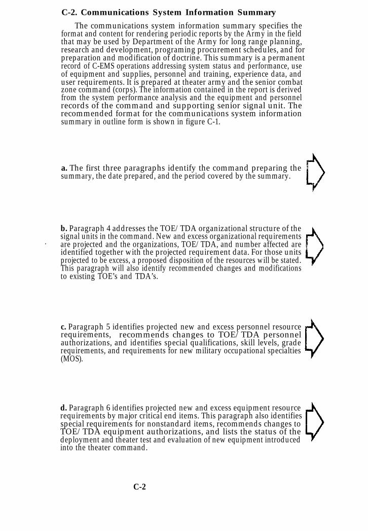
C-2. Communications System Information Summary
The communications system information summary specifies theformat and content for rendering periodic reports by the Army in the fieldthat may be used by Department of the Army for long range planning,research and development, programing procurement schedules, and forpreparation and modification of doctrine. This summary is a permanentrecord of C-EMS operations addressing system status and performance, useof equipment and supplies, personnel and training, experience data, anduser requirements. It is prepared at theater army and the senior combatzone command (corps). The information contained in the report is derivedfrom the system performance analysis and the equipment and personnelrecords of the command and supporting senior signal unit. Therecommended format for the communications system informationsummary in outline form is shown in figure C-1.
a. The first three paragraphs identify the command preparing thesummary, the date prepared, and the period covered by the summary.
b. Paragraph 4 addresses the TOE/TDA organizational structure of thesignal units in the command. New and excess organizational requirements
. are projected and the organizations, TOE/TDA, and number affected areidentified together with the projected requirement data. For those unitsprojected to be excess, a proposed disposition of the resources will be stated.This paragraph will also identify recommended changes and modificationsto existing TOE’s and TDA’s.
c. Paragraph 5 identifies projected new and excess personnel resourcerequirements, recommends changes to TOE/TDA personnelauthorizations, and identifies special qualifications, skill levels, graderequirements, and requirements for new military occupational specialties(MOS).
d. Paragraph 6 identifies projected new and excess equipment resourcerequirements by major critical end items. This paragraph also identifiesspecial requirements for nonstandard items, recommends changes toTOE/TDA equipment authorizations, and lists the status of thedeployment and theater test and evaluation of new equipment introducedinto the theater command.
C-2

C-3

e. Paragraph 7 evaluates the communications systems performance. Thetraffic handling assessment addresses the command and areacommunications systems separately. For both systems, the total number oftelephone calls by precedence are reported for the period together with thepercent change from the last period, the system grade of service, and theaverage holding time. Problem areas are identified and analyzed withrespect to the system, switches, and trunks. A qualitative evaluationstatement is made concerning the acceptability of the grade of service andmeans to improve the system performance. For both systems, the totalnumber of teletypewriter messages and the number of data cards byprecedence are reported for the period together with the percent changefrom the last period and the speed of service based on elapsed time betweenfiling time (TOF) and transmission time (TOT). Problem areas areidentified and analyzed with respect to the terminal and relay facilities, anda qualitative statement is made concerning the acceptability of thecommunications service provided. Similar kinds of information will beincluded for facsimile, closed circuit television, and messenger/courierservices. Subparagraph B identifies special system problems, such assystem security, radio frequency interference, system interface, andallied/indigenous interface considerations. Subparagraph C may be usedto recommend doctrinal changes and to report changes to the command onunit SOP based on an analysis and evaluation of operating problemsencountered. Subparagraph D addresses frequency resources, identifyingnew frequency requirements, and frequencies found to be excess torequirements. Use of automated frequency management procedures toprovide CEOI items will be reported in a narrative summary as well astransmission anomalies peculiar to the area of operations and otherfrequency problem areas.
f. Paragraph 8 will address logistic support of the communicationssystems; in particular, critical supply and maintenance requirements,special transportation and handling requirements, special CONUS and/oroffshore procurement requirements, as well as the recovery andreclamation of C-E materiel.
C-4
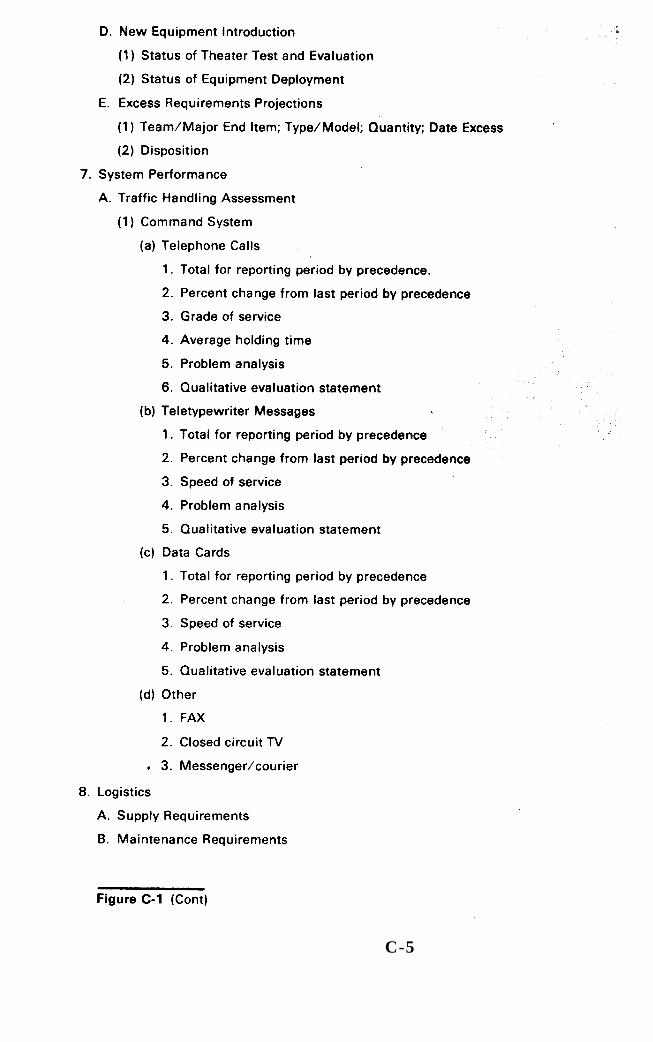
C-5

g. Paragraph 9 will depict the status of the command training structureconsolidated by level of command. Subparagraph A presents the commandschooling status in terms of the MOS and non-MOS training courses thatare conducted by the command. Subparagraph B projects the CONUSstudent output to the command that is required to satisfy MOSrequirements, based on anticipated personnel rotation, losses, andoperational requirements projected by paragraph 5A. Subparagraph Cprovides recommendations for changes in the POI for CONUS schoolsbased on operational experiences. The purpose of these recommended POIchanges are to provide the command with course graduates better qualifiedto assume assigned organizational duties with a minimum of OJT or otheradditional training. Subparagraph D provides recommendations for theestablishment of new courses (both MOS producing and non-MOS courses)to develop skills which cannot be provided by modification of existingschool courses.h. Paragraph 10 gives considerations that may influence budget andprogram actions by Department of the Army. Subparagraph A discussesnew project requirements, such as new stations/facilities, new systems,class IV signal projects, and associated construction. Subparagraph Breports on the status of current projects, to include the funding of projectsbeing performed by both military and civilian contractor effort.Subparagraph C identifies projects completed during the reporting periodand evaluates their impact on the communications systems. SubparagraphD projects contractual support requirements for goods and services, andreports and contractual obligations incurred and the funding status ofcontractual support during the reporting period.i. Paragraph 11 provides general information not covered by the otherparagraphs of the communications system information summary. Thisinformation may identify test and evaluation programs in progress in thecommand, report the status of these programs, and provide an evaluation ofthe results as they impact the command mission. Additional informationcan include such items as recommended doctrine and policy changes andrequirements for publications and manuals essential to the operation of thecommunications systems.
C-6

C-7

C - 8

C-3. C-E Trouble Record (DA FORM 4617-R)
DA Form 4617-R, C-E Trouble Record, will be reproduced locally on8“ x 10½” paper in accordance with Fig C-2 and C-3. The C-E trouble recordshould be numbered to enable easy filing and referencing by operators andsupervisors. It is prepared by the equipment operator and submitted to theCNCE. The trouble record is prepared as follows and should be kept on file inaccordance with unit SOP or AR 340-2.
a. Heading.(1) DTG-Enter the date-time group showing time of record. Use Zulutime unless otherwise directed.(2) Record Number-Self-explanatory, chronologically for the currentradio day.
b. Blocks.l-Self-explanatory.2-Self-explanatory.3-Restoration priority.4-Reroute path (if applicable).5-Identify location of trouble, time out, and estimated time ofrestoration.6-Show suspected or actual RFO. Use RFO codes listed on the reverseside of the form (fig C-3).7-Identify affected equipment and personnel. Use RSC codes (fig C-3).8-Briefly explain corrective action and indicate any assistancerequired.9-Use to amplify any aspect of the trouble situation.10a-If more than one trouble is encountered, show DTG of first.10b-Show actual restoration.10c-Indicate verified RFO.10d-Show time reported to CNCE(M), CSCE, or other appropriatemanagement element.
c. The classification of the record will be written or stamped prominently attop and bottom of the record.
C-9

C-10


C-4. Operational Resource Record (DA FORM 4618-R)
a. DA Form 4618-R, Operational Resource Record, will be reproducedlocally on 8“ x 10½” paper in accordance with Fig C-4 and C-5. The opera-tional resource record (ORR) is submitted by a communications node anddistributed to appropriate C-EMS elements. The purpose of the ORR is toprovide an up-to-date status report on the extent of C-E resources committed,the capability available, and remaining available resources for planningand restoration of service purposes.b. The operational resources record is originated at company level and,after approval by the company commander, is passed to the CNCE(M). Atthe same time, the record is sent to battalion headquarters throughcommand channels. At battalion headquarters, the record is reviewed and,after approval by the battalion commander, is passed to the CNCE(M) andCSCE at battalion level and, simultaneously, through channels to brigadeand group. It is subject to review and approval at these levels and is thenforwarded to the next higher CSCE. The senior signal unit puts theinformation in its data base which is made available to the major commandC-E staff. When a signal group is part of a theater army communicationscommand, the information is passed through command channels toTACCOM headquarters and made available to the CSPE of the theaterarmy C-E staff. The records may be consolidated at each successivecommand level or passed in their original form through channels for reviewand approval.c. The ORR record format is shown in figure C-4. Boxes 1 through 4 provideinformation for a message heading. The main body of the record is dividedinto two parts; the team status and critical shortages. The composition ofthe various teams to be recorded on are shown in figure C-5. Thealphanumeric code for the team is shown along with the normalauthorization by type of signal equipment, power units, vehicle, andpersonnel. Teams are categorized as committed, available, or incomplete.“Committed” means in use, “available” means operational butuncommitted, and “incomplete” means the team is lacking an essentialequipment item or team member and thus has a reduced capability. It isintended that the readiness of a team be a command decision. If, forinstance, the commander believes a team can perform with acceptableefficiency with less than the full complement of authorized personnel, theteam should be categorized “available,” with the missing key personnelshown under personnel shortages. The incomplete team category should beused when the operational equipment and qualified personnel are notavailable to the extent that the team is deemed to be incapable of effectiveperformance. The teams are grouped by type of function for easy reference.In box 5, team codes are listed in column A with their status indicated bynumbers in columns B, C, and D. Box 6, Critical Shortages, refers to themajor equipment items or personnel requirements needed to convert theincomplete teams to an operational status.
C-12

C-13
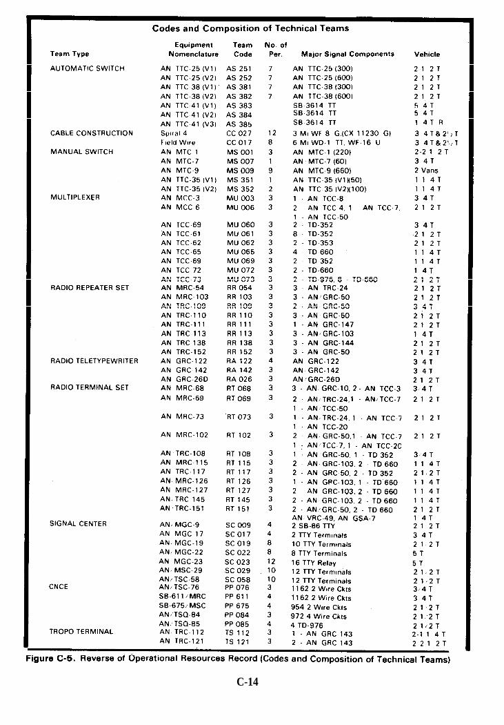
C-14

C-5. Traffic Status Record (DA FORM 4619-R)
a. DA Form 4619-R, Traffic Status Recortd, will be reproduced locally on8" x 10½" paper in accordance with Fig C-6. The traffic status record is pre-pared on a periodic basis (usually daily) by the CNCE(M) based on informa-tion provided by both the telephone switch and the telecommunicationscenter and is normally sent to the controlling CSCE for traffic engineering.b. The traffic status record data is used—
(1) To verify previously stated communications requirements.(2) To react to changes in force structure or the tactical situation.(3) For optimizing the communications system remaining afterdamage occurs.(4) To predict future changes to the system by observing trends.(5) To justify equipment and personnel needs.
Note: With the introduction of automatic switches, timely andaccurate reporting will be essential to the centralized management aspectsof reprogramming switches to rebalance or reconstitute degraded portions ofthe communications system.
C-15
c. A sample record is shown in figure C-6 and is explained below.
(1)
(2)
Boxes 1 through 4 provide information for a message heading.
Box 5 lists the time covered by the record period (use DTG for both“to” and “from”).
(3) The record is divided into four principal areas: total voice traffic,voice traffic by trunk group, total message/data traffic relay andterminal, and traffic moved by messenger.
(4) Boxes 6 and 7 are structured to conform with the output of theAN/TTC-38. The data for box 8 can be collected at the relay for manualtape relay operation. Data for boxes 9 and 10 are provided by thetelecommunications center record section.
C-16

C-17

C-6. Special Communications Authorization Request(DA FORM 4620-R)
a. DA Form 4620R, Special Communications Authorization Request, willbe reproduced locally on 8“ x 10½" paper in accordance with Fig C-7. Aspecial communications authorization request (SCAR) is submitted whenservice over and above that prescribed in doctrine/SOP is required by a user.The SCAR should be submitted to the appropriate CNCE(M) which willeither provide the service or will forward the request to higher headquarterswhen it does not have the authority to approve the request.
b. The SCAR consists of two principal parts: identification andjustification of the user’s requirement, and evaluation and decision by theC-EMS elements involved. Boxes 1 through 4 provide information for amessage heading.
c. The subscriber information called for in boxes 5a through 5f is requiredto provide the requested service; the information in box 5g is critical to theevaluation and approval processes. The justification should clearlydemonstrate why the service prescribed by doctrinal policy does not meetthe user operational requirements. The assessment of the communicationsrequest (box 6) is prepared by the approval of the supporting signal unitcommander. It requires consideration of the resources needed andavailable, contingency plans, unit priorities, planned force structurechanges, and an estimate of possible system implication beyond the localnodal network.
C-18

C-19

C-7. Telecommunications Service Order(DA FORM 4621-R)
a. DA Form 4621-R, Telecommunications Service Order, will be repro-duced locally on 8“ x 10½” paper in accordance with Fig C-8. The telecom-munications service order (TSO) is a technical directive that is issued to asubordinate facility or operating command (e.g., elements of the CSCE atany level, the C-E staff of a major command, the unit staff of a signal unit, orthe CNCE of a node). All TSO’s in a tactical situation will be classifiedCONFIDENTIAL or higher.
b. The purpose of the TSO is to direct the performance of an individual taskor groups of tasks for the implementation of signal orders, signal annexes tocommand operations orders, restoration of service in response to troublereports, approved special communications authorization requests, or SOPdoctrinal communications entitlements. The TSO form is structured todirect the installation and operation of all types of communicationssystems under a wide variety of situations. It is designed to be transmittedby secure electronic means from higher authority to the operating signalunits.
c. The informational content of each block on the TSO form is describedbelow. A sample format for an electrically transmitted TSO is shown infigure C-9.
Box 1. Enter the unit name and address of the C-EMS facility whichdirects the action ordered by the TSO. Include site designator ifrequired.Box 2. Enter the unit name and address of the C-EMS facility to whichthe TSO is directed for action. Routing designators will be added whenthe TSO is to be sent over common-user facilities. Include sitedesignator if required.Box 3. Enter the unit name and address of the C-EMS facility to which“information only” copies of the TSO are to be sent. Include sitedesignator if required.Box 4. Designate the security classification for the information in theTSO: Unclassified, Confidential, Secret, Top Secret.Box 5. Designate the TSO precedence for transmission: Routine,Priority, Immediate, Flash, Flash Override.Box 6. Identify the TSO number and DTG of issue.Box 7. Identify the source document from which the implementationinstructions contained in the TSO were derived. The source documentmay be a signal order, another TSO, other technical directives, orverbal orders from the commander.
(Continues on page C-22)
C-20

C-21

(ContinuedfrompageC-20)
Box 8A. Check off the type of action which the TSO directs. The actionchecked will be transmitted.Box 8B. Enter the DTG which is the deadline for completing the action.Box 8C. Enter the restoration priority for the action desired.Box 8D. Enter the designator of the station or facility affected by theTSO.Box 8E. Using the standard numbering procedures, enter thedesignator of the system or circuit affected by the TSO.Box 8F. Enter the routing instructions applicable to the actiondirected. This will include any patching instructions.Box 8G. Identify the using organization if the system/circuit isspecifically assigned.Box 8H. Identify interface requirements such as with cable orcommercial systems.Box 8I. Enter any types of conditioning equipment required.Box 8J. Enter the (1) type of wire or cable directed, (2) unit name,and/or (3) coordinates of terminal of wire/cable system/circuit.Box 8K. These entries are appropriate to the multichannelcommunications systems. A system or link will require entries in (1)and (2) and may require multiple entries at (3) corresponding to thenumber of relays required. The entries in items (1) and (2) arecoordinates describing the location of terminal A and/or terminal B;the antenna azimuth (AZ), height (HT), and polarization (PLRZ); andsend (S) and receive (R) frequencies and the station call sign. For each ofthe relays (3), enter the relay site number, coordinates of the location,and the call sign of the relay station. For each leg, the send (S) andreceive (R) frequency will be identified along with the antenna azimuth(AZ), height (HT), and polarization (PLRZ) on that leg.Box 9A. Check off the applicable type of equipment action. The actionwill be transmitted together with—Box 9B–equipment type/model identification code (TD-660, AN/TRC-138, etc.),Box 9C—quantity of each type, andBox 9D—location at which the equipment action is required.Box 10 will contain additional information amplifying instructions asappropriate (use back of form if necessary). The block indicatingcompletion and reporting of the action will be completed and theverification block signed.
C-22

C-23
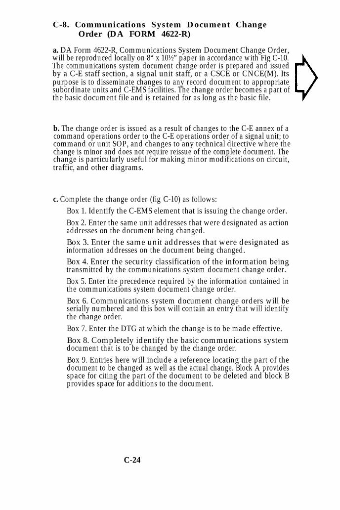
C-8. Communications System Document ChangeOrder (DA FORM 4622-R)
a. DA Form 4622-R, Communications System Document Change Order,will be reproduced locally on 8“ x 10½” paper in accordance with Fig C-10.The communications system document change order is prepared and issuedby a C-E staff section, a signal unit staff, or a CSCE or CNCE(M). Itspurpose is to disseminate changes to any record document to appropriatesubordinate units and C-EMS facilities. The change order becomes a part ofthe basic document file and is retained for as long as the basic file.
b. The change order is issued as a result of changes to the C-E annex of acommand operations order to the C-E operations order of a signal unit; tocommand or unit SOP, and changes to any technical directive where thechange is minor and does not require reissue of the complete document. Thechange is particularly useful for making minor modifications on circuit,traffic, and other diagrams.
c. Complete the change order (fig C-10) as follows:Box 1. Identify the C-EMS element that is issuing the change order.Box 2. Enter the same unit addresses that were designated as actionaddresses on the document being changed.Box 3. Enter the same unit addresses that were designated asinformation addresses on the document being changed.Box 4. Enter the security classification of the information beingtransmitted by the communications system document change order.Box 5. Enter the precedence required by the information contained inthe communications system document change order.Box 6. Communications system document change orders will beserially numbered and this box will contain an entry that will identifythe change order.Box 7. Enter the DTG at which the change is to be made effective.Box 8. Completely identify the basic communications systemdocument that is to be changed by the change order.Box 9. Entries here will include a reference locating the part of thedocument to be changed as well as the actual change. Block A providesspace for citing the part of the document to be deleted and block Bprovides space for additions to the document.
C-24

C - 2 5

C-9. Master Station Log
a. The master station log (fig C-11) file is maintained at each facility and isa chronological history of all significant events. Shift supervisors jointlyreview the log at change of shift for completeness and accuracy of theentries. The facility supervisor may review the form and sign it to indicateacceptability prior to filing.
b. The ACTION/EVENT column is used to—(1) Briefly describe the event.(2) Record shift changes including the names of personnel coming onduty.(3) Record the status of circuits at change of shift. This insures thatshift supervisors are aware of the status of any circuit troubles oroutages and the remedial actions taken or required.
c. For entries not directly related to circuits, leave the CHANNEL ORCIRCUIT column blank and enter information (e.g., generator failure, staffvisit, etc.) in the ACTION/EVENT column.
C-26
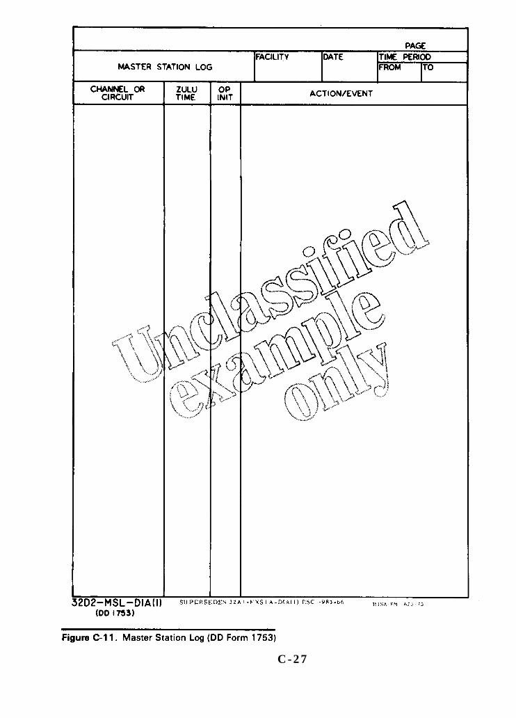
C - 2 7

C-10. System and Circuit Status Record(DA FORM 4623-R)
a. DA Form 4623-R, System and Circuit Status Record, (cards 1 and 2,front and back) will be reproduced locally on 8“ x 10” card stock paper inaccordance with Fig C-12, C-13 and C-14. The system and circuit statusrecord is maintained by circuit controllers in the CNCE(T). It providesdetailed, current-status information on all terminating and patched-through systems and circuits. The record is designed to contain the informa-tion required on both systems and circuits as well as groups of circuits.
Note: This record and the system and circuit status record-systemchannel allocation (covered in the next paragraph) are temporary filesmaintained at the CNCE(T) during the time that each circuit is active. Theinformation entered on the records is obtained from TSO's received by theCNCE(T) and from the results of testing and monitoring by the CNCE(T).The term "system" as used here denotes a radio multichannel or cable linkbetween two communication nodes.
b. Front of status record, card 1 (fig C-12).Box 1. Enter the number that will identify the system or circuit inaccordance with the prescribed system/circuit numbering system.Box 2. This box will contain two entries for both systems and circuits.These two entries will designate the terminal nodes of thesystem/circuit. The node entered first is to be the controlling node.Box 3. For system records, identify the type of system; e.g., radio, wire,cable. For circuit records, identify the communications node utilizingthe circuit; e.g., voice, TTY, voice/TTY, data, fax, etc.Box 4. Identify the signal unit at which the controlling CSCE isassigned.Box 5. Enter the restoration priority in accordance with prescribedpriority procedures.Box 6. Identify the authority, technical service order, VOCO,other/directives, and the DTG authorizing the activation of thesystem/circuit.Box 7. Identify the DTG on which the system/circuit was activated.Box 8. For system records, this box will contain an entry only when thesystem goes to a single user. The entry will identify the user. The boxwill be left blank when the system serves multiple users. For circuitrecords, this entry will identify either the user to whom the circuit isassigned or the terminating signal facility.Box 9. Identify the transmission equipment, video patch equipment (asappropriate), and multiplexer which is associated with the system atthe node. This entry will be completed for both system and circuitrecords.Box 10. Identify the type of switchboards, teletypewriter relay, otherequipment (instruments), or communications facilities which utilizethe circuit. For system records, this box will be left blank unless all thecircuits in the entire system are terminated in the same type equipment.Box 11. Identify the activity responsible for the equipment/facilitiesshown in box 10 together with the telephone number at which they canbe contacted.
C-28

Box 12. For system records, identify the type of equipment. If multipleentries would be required for any type of item, the presence of the itemwill be indicated by a checkmark. For circuit records, identify the typeequipment used on that circuit at that node.Box 13. For system records, the boxes will not be used. For circuitrecords, identify the type equipment used on that circuit at that node.Box 14. For system records, the boxes will not be used. For circuitrecords, identify the type equipment used on that particular circuit atthe node designated.Box 15. Identify routing of system, circuits, and/or groups asappropriate. System routing identifies multichannel sites, asappropriate.Box 16. For system records, the cable designation for each 12/24-channel group (26 per cable) will be identified. The column labled CHwill show the number of channels in the group. For circuit records, thegroup and channel that bring the circuit to the CNCE will be identified.If the circuit is terminated at the node, only one entry is shown. If thecircuit is patched through the node, then two entries will be required.The system number will be shown on the heading line and is a crossreference to system channel allocation shown on card 2. For circuitgroups patched through the node, two entries will be required showingthe groups and the number of channels utilized.Box 17. Indicate the locations on the patch panel where the circuit isbrought IN from the system terminal equipment and is connected OUTto circuit terminal equipment or to a group designated in box 16 forthrough circuit group patches. Individual circuit entries must be shownfor group patches.
C-29

c. Rear of status record, card 1 (fig C-13). The entries on this side of therecord card are used for system/circuit outages. If the entire system goesdown, this outage is recorded on the system record card. If only a singlechannel goes out, the outage is recorded on the circuit record card.
Box 18. Fill out as follows:Block A. DTG OUT. Identify the DTG at which the system/circuitwas discovered as being out.Block B. DTG IN. Identify the DTG at which the system/circuitwas restored for service to the user.Block C. RFO. Identify the reason for the system/circuit outage.The entries will use the same RFO codes that are used with thetrouble report.Block D. ACTION TAKEN. Describe how the system/circuittrouble was corrected or how the restoration was effected.Examples of these entries would be: transmit frequency changed toeliminate RFI, maintenance personnel replaced module in mux,antenna repaired/replaced, new cable laid to replace destroyedcable from mux to xmtr,
Box 19. This section will be used to recordsystem/circuit modifications. The entries in the
implementation ofsystem and circuit
status record cards will be made in pencil so that when minor changesoccur, the new information can be used to record the box number(s)which were changed, authority will list the TSO number and issuingheadquarters and the DTG of the TSO or other order directing thesystem/circuit modification.
Box 20. This section will be used to record any other pertinentinformation not shown elsewhere on the card or for amplification ofany entries on the record.
C-30

C-31

C-11. System and Circuit Status Record-SystemChannel Allocation (Card 2, Front and Back)
a. Both the system allocations and the restoration priority are recorded onthis card (fig C-14). One card can be used for 48 channels in increments of 12-channel groups. If a system has 96 channels, two cards are required. Thisrecord is completed and filed with the system and circuit status record asexplained in the note in the preceding paragraph.
b. Boxes 1 through 6. The heading information is printed at the top of oneside and the bottom on the other side to allow for use in either a box or fliptype file container. The information in the heading is the same as on cardone with the addition of an entry, box 6, identifying the number of 12-channel groups in the system.
c. The entry under “group” will be made to designate the 12-channel groupnumber.
d. The circuit number will be entered on the line opposite the allocatedchannel and the restoration priority for the individual circuits will beentered on the appropriate line.
C-32
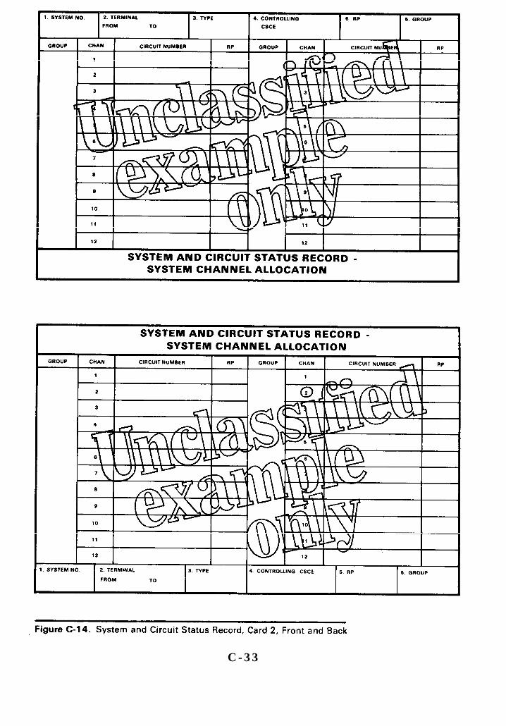
C - 3 3

C-12. Circuit Routing List
a. The circuit routing list (fig C-15) is used to provide information fortandem connections and to serve as the basis of instructions to operatingunits for patching and terminations. The list has the same status as thecircuit diagram. The senior signal unit CSCE, upon receipt of the chart,places the information in the automatic database at the CSCE and sends toits appropriate subordinate units that portion(s) of the list for whichinstallation is being assigned. Instructions to implement the list will be sentby the senior signal unit to its subordinate units as a technical service orderor other directive.
b. The list provides the CNCE with information regarding the originatingand terminating points, the type of service provided, the use of the circuit,and the circuit within the group.
Column 1 of the circuit routing chart numerically lists each channel ofthe system using two digits (e.g., 01, 02, 03; 13-24; 25-36; etc.).Column 2 contains the circuit designator based on information fromappendix B.Column 3 contains the priority designator based on information fromappendix B.Column 4 indicates the circuit type taken from appendix B.Column 5 indicates the specific origin of circuit; e.g., 52d Div S2, IIICorps G3, CSPE, etc. A switch may be designated by PR-SL number.Columns 6 through 9 list the system(s) through which the circuit ispatched. Where necessary, more than four systems may be listed. Thefirst entry will be the point of origin and the last entry will be the pointof termination. The channel number of the system carrying the circuitis indicated by a two-digit number affixed at the end of the systemdesignator.
Column 10 indicates the settings for the equipment “2-wire/4-wire” and“ringer” (signaling mode) switches. For example, for channel 04 offigure C-15, column 10 (labeled CHAN SETTING) has 4W OFF/2WOFF indicated. Settings on the left of the slash mark (/) are to be used bythe controlling terminal (term A), while the settings on the right of theslash mark are for the other end (term B). In the example, terminal 21will set the equipment’s (e.g., CV-1548) 2-wire/4-wire switch to 4W andthe signaling mode switch (on panel 18A3, channel 6) to the OFFposition. Terminal J1 will set its equipment 2W/4W switch to 2W and itssignaling mode switch to OFF.
Note: The word ON in column 10 refers to "ringer on" (on someequipment) and to the “AC” position of the signaling mode switch of theCV-1548.
Column 11 indicates the specific termination point of the circuit; e.g.,S3, CO, TCC, etc.Column 12 indicates the system designator which identifies the CRC. Italso establishes the system priority, which will be the priority of thehighest priority circuit excluding the engineering/control channel.
C-34

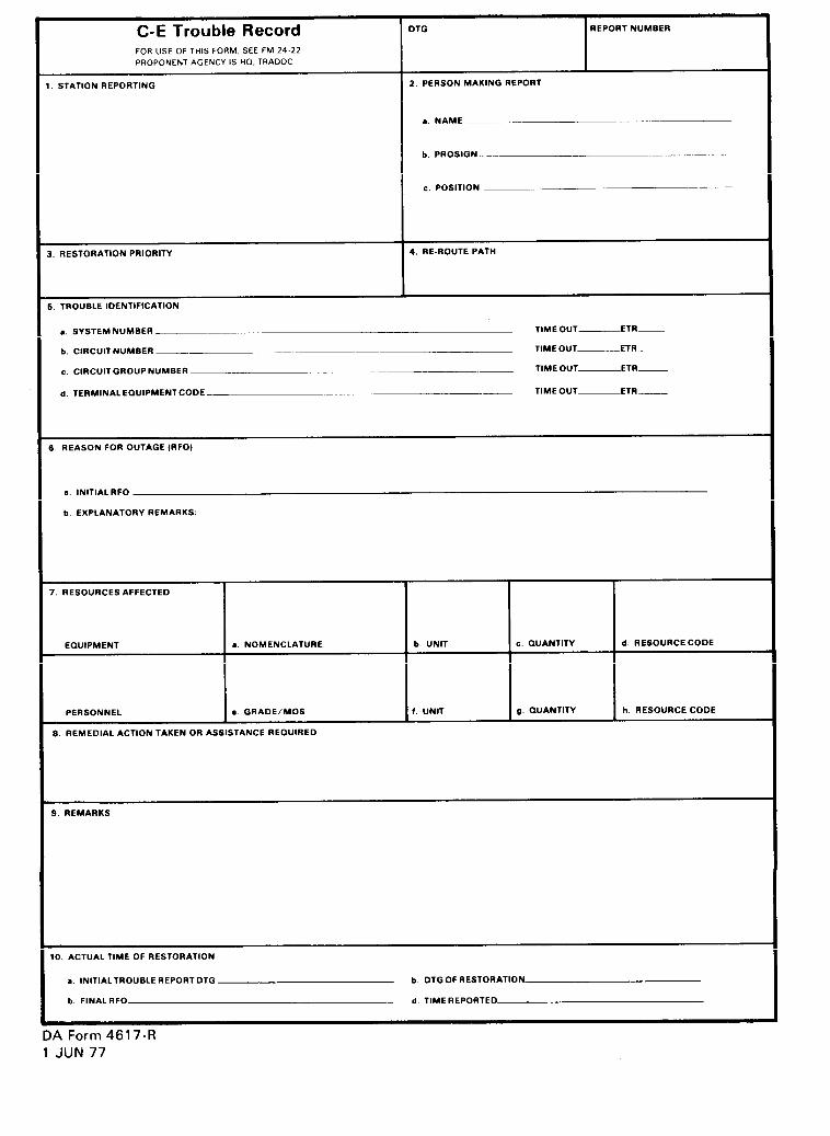

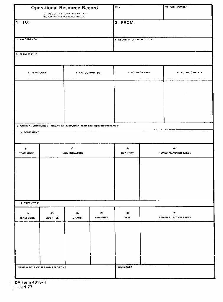
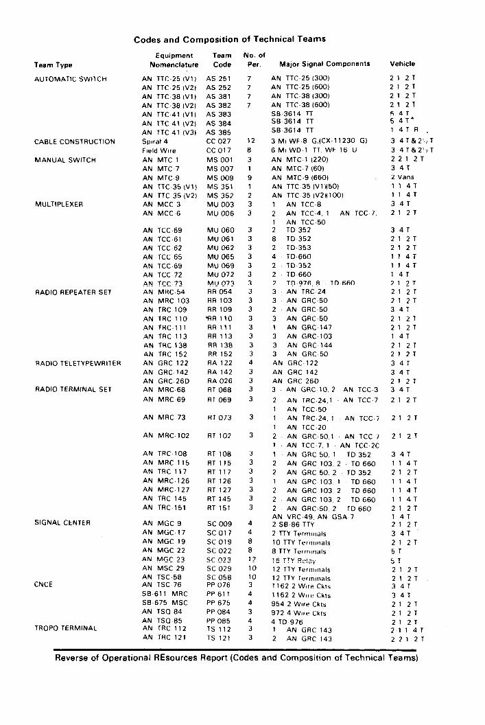


INDEX
Index 1

Index (Cont)
Index 2

FM 24-22
30 JUNE 1977
By Order of the Secretary of the Army:
BERNARD W. ROGERSGeneral United States Army
Chief of Staff
Official:
PAUL T. SMITHMajor General, United States Army
The Adjutant General
DISTRIBUTION:
Active Army, USAR, and ARNG: To be distributed in accordance with DA Form 12-11 A, Require-ments for Tactical Communications Doctrine; and Field Radio Techniques (Qty rqr block no. 211and 215).
Additional copies can be requisitioned (DA Form 17) from the US Army Adjutant General Publica-tions Center, 2800 Eastern Boulevard, Baltimore, MD 21220.
★ U.S. GOVERNMENT PRINTING 0FFICE: 1995-388-421/42096