Embed Size (px)
Citation preview
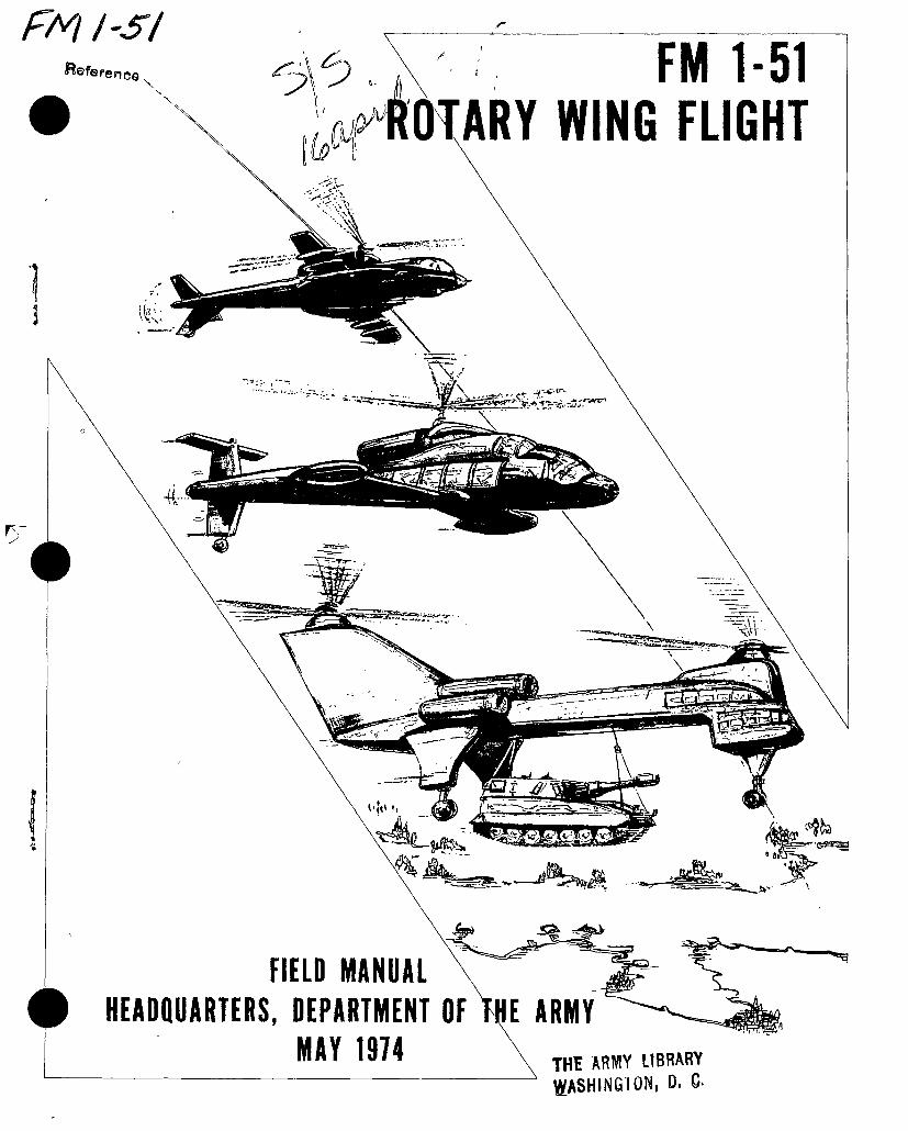
FM FS! FM 1-51
WING FLIGHT “fence
\N
Si
4i-
\ %V1
F *7
■€> > »1
5^ 'S
E ARMY FIELD MANUAL
HEADQUARTERS, DEPARTMENT OF MAY 1974
THE ARMY LIBRARY WASHINGTON, D. C-
*
I’D SAY IT’S ABOUT 95% KNOWLEDGE, PREPLANNING,
PROJECTION, AND PREDICTION, AND ABOUT 5% FEEL,
TOUCH, COORDINATION, AND APPLICATION.
<r
«
THE PILOT’S PHILOSOPHY

FM 1-51
FIELD
No. 1-
MANUAL
51
HEADQUARTERS DEPARTMENT OF THE ARMY WASHINGTON, D.C., 30 May 197U
ROTARY WING FLIGHT
CHAPTER
Section
CHAPTER
Section
1. 2.
I. II.
III. 3.
I. II.
III. IV. V.
VI.
CHAPTER
Section
VII. 4. I.
II. III.
CHAPTER 5.
6.
Section
CHAPTER
Section
7. I.
II. 8.
9. I.
II.
III. IV.
CHAPTER 10.
Section I. II.
III. IV. V.
VI. VII.
VIII. CHAPTER 11.
APPENDIX A.
INDEX
Frontispiece GENERAL BASIC HELICOPTER AERODYNAMICS Dynamics and Aerodynamics Aerodynamics of Autorotation Effect of Atmosphere on Flight GENERAL HELICOPTER FLIGHT TECH-
NIQUES Introduction Ground Operations and Hovering Normal Takeoff Airwork Normal Approach Maximum Performance Takeoff and Steep Ap-
proach Running Takeoff and Landing AUTOROTATIONS Basic Considerations Practice Autorotations Presolo Phase Practice Exercises NIGHT FLYING CONFINED, REMOTE, AND UNIMPROVED
AREA OPERATIONS FLOAT AND SKI OPERATIONS Float Operations Ski Operations EXTERNAL LOAD OPERATIONS RESCUE HOIST OPERATIONS Introduction Crew Responsibilities and Communications Pro-
cedures Recovery Procedures Safety and Emergency Procedures FORMATION FLYING Introduction Principles of Formation Flying Types of Formations Formation Tactics Inadvertent Instrument Flight Conditions Night Formation Flying Multiple Flight Formation Formation Dispersion Maneuvers PRECAUTIONARY MEASURES AND CRITI-
CAL CONDITIONS REFERENCES
Paragraph
1-1—1-6
2-1—2-36 2-37—2—44 2^15—2-48
3-1, 3-2 3-3—3-10 3-11—3-14 3-15—3-23 3-24—3-26
3-27—3-30 3- 31, 3-32
4- 1—4-13 4-14—4-18 4- 19—4-28 5- 1—5-7
6- 1—6-6
7-1—7-7 7- 8—7-18 8- 1—8-6
9-1—9-4
9-5, 9-6 9-7—9-12 9- 13—9-15
10- 1, 10-2 10-3—10-5 10-6—10-9 10-10—10-14 10-15—10-18 10-19—10-21 10-22—10-24 10- 25, 10-26
11- 1—11-11
Page
1-1
2-1 2-23 2-29
3-1 3-2 3-5 3- 7
3-15
3-17 3-19
4- 1 4-4 4- 5 5- 1
6- 1
7-1 7- 6 8- 1
9-1
9-2 9-5 9-8
10-1 10-2 10^1
10-11 10-24 10-24 10-27 10-29
11-1 A-l
Index-1
"This manual supersedes TM 1—260, 21 May 1965, including all changes.

s
J
I
FM 1-51
CHAPTER 1
GENERAL
1-1. Purpose
This manual provides a reference for the— a. Initial entry rotary wing aviator student
during the primary and advanced stages of training.
b. Ground instructor as a reference textbook for presenting instruction.
c. Check pilot as a guide for the flight evalua- tion of the student’s fundamental knowledge of rotary wing flight.
d. Rated aviator as a guide when undergoing MOI and aircraft qualification training.
e. Unit commander as a guide for unit train- ing when conducting specialized training (e.g., rescue hoist operations).
1—2. Flight Techniques
a. While this manual covers the fundamental rotary wing flight techniques applicable to ini- tial entry rotary wing aviators, instructors, and check pilots, it is important for the user to realize that the mission of his unit, the threat, and the changing environment may require low level, contour, or nap-of-the-earth (NOE) flight techniques.
b. In a high air defense threat environment, the aviator will be required to apply techniques and tactics which seek to minimize aircraft vul- nerability during the accomplishment of his mission.
c. The threat anticipated for this environ- ment makes flying above NOE altitude in the vicinity of the forward edge of the battle area a potentially higher risk than may be offset by expected tactical gains.
d. Tactical unit training guidelines which stress these aviation tactics and techniques can be found in TC 1-15.
1-3. Scope
This manual covers— a. Basic helicopter aerodynamics. b. Flight techniques. c. Autorotations. d. Night flying. e. Operations in confined, remote, and unim-
proved areas.
/. Float and ski operations. h. Rescue hoist operations. i. Formation flying. j. Precautionary measures and critical condi-
tions.
1-4. International Air Standardization Agreements
a. Transport of Cargo by Helicopter. Chapter 8 is the subject of an international air standar- dization agreement, ASCC Air Standard 44/32, Technical Criteria for the Transport of Cargo by Helicopter.
b. Formation flying. Chapter 10 is the subject of an international air standardization agree- ment, ASCC Air Standard 44/34, Tactical For- mation Flying by Helicopter.
1-5. Helicopter Configuration and Perfor- mance
Information on helicopter configuration and performance under particular conditions is found in appropriate 55-series-10’s (operator’s manuals).
1-6. User Comments
Users of this publication are encouraged to submit recommended changes and comments to improve the publication. Comments should be keyed to the specific page, paragraph, and line of the text in which the change is recommended. Reasons will be provided for each comment to insure understanding and complete evaluation. For your convenience, a self-addressed DA Form 2028-1, (Recommended Changes to Publications and Blank Forms) is available as a tear-out sheet in the back of this publication. If this form has been removed, use DA Form 2028 and forward direct to the Commandant, United States Army Aviation School, ATTN: ATST-CTD-D, Fort Rucker, Alabama 36360.
1-1

I
FM 1-51
CHAPTER 2
BASIC HELICOPTER AERODYNAMICS
Section I. DYNAMICS AND AERODYNAMICS
2-1. General
An aviator needs to understand the physical laws related to dynamics and aerodynamics and how they apply to the helicopter and its control. This section defines, explains, and illustrates basic dynamic and aerodynamic principles which a rotary wing aviator would be required to know. For additional information on basic helicopter aerodynamics, see FAA Advisory Circular (AC) 61-13, Basic Helicopter Handbook.
2—2. Types of Airfoils
An airfoil is any surface designed to produce a lift or thrust reaction when air passes over it. Airfoils include airplane wings, helicopter rotor blades, and propellers. Airplane wings and helicopter rotor blades have airfoil sections with upper and lower surfaces carefully engineer- designed for a specific set of flight characteris- tics. Some airfoil designs may be less efficient in a specific area yet permit higher airspeeds. Other combinations of upper and lower surface designs may generate more lift but may have a very wide center of pressure (para 2-4) travel. Usually the designer must compromise to ob- tain an airfoil that offers the best flight charac- teristics for the mission to be performed.
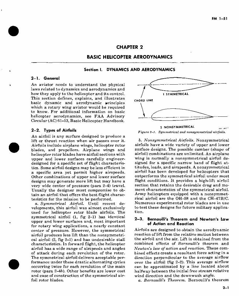
a. Symmetrical Airfoil. Until recent de- velopments, this airfoil was almost exclusively used for helicopter rotor blade airfoils. The symmetrical airfoil (1, fig 2-1) has identical upper and lower surfaces and, most important for rotary wing applications, a nearly constant center of pressure. However, the symmetrical airfoil produces less lift than the nonsymmetri- cal airfoil (2, fig 2-1) and has undesirable stall characteristics. In forward flight, the helicopter airfoil has a wide range of airspeeds and angles of attack during each revolution of the rotor. The symmetrical airfoil delivers acceptable per- formance under these drastic alternating cycles occurring twice for each revolution of the main rotor (para 2-46). Other benefits are lower cost and ease of construction of the symmetrical air- foil rotor blades.
1 SYMMETRICAL
CHORD LINE
2 NONSYMMETRICAL avn k13 ,
Figure 2—1. Symmetrical and nonsymmetrical airfoils.
b. Nonsymmetrical Airfoils. Nonsymmetrical airfoils have a wide variety of upper and lower surface designs. The possible camber (shape of airfoil) combinations are unlimited. An airplane wing is normally a nonsymmetrical airfoil de- signed for a specific narrow band of flight at- titudes, loads, and airspeeds. A nonsymmetrical airfoil has been developed for helicopters that outperforms the symmetrical airfoil under most flight conditions. It provides a high-lift airfoil section that retains the desirable drag and mo- ment characteristics of the symmetrical airfoil. Army helicopters equipped with a nonsymmet- rical airfoil are the OH-58 and the CH-^47B/C. Numerous experimental rotor blades are in use to test these designs for future military applica- tion.
2—3. Bernoulli's Theorem and Newton's Law of Action and Reaction
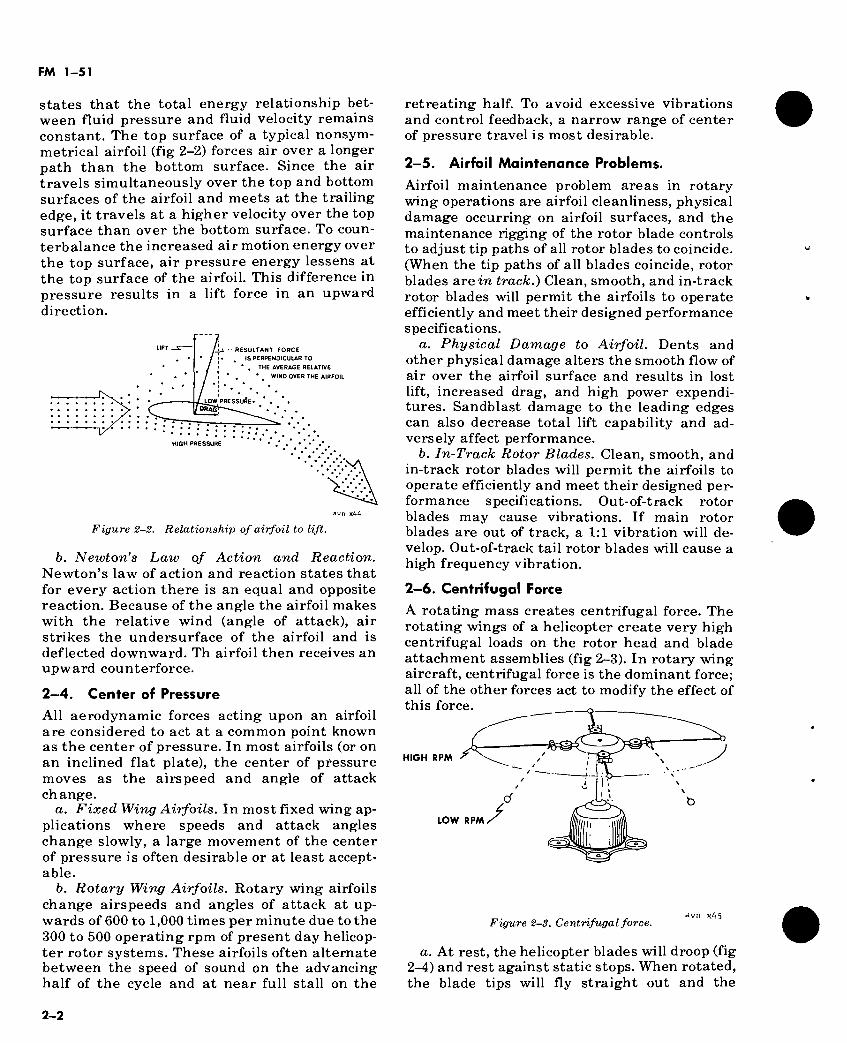
Airfoils are designed to obtain the aerodynamic reaction of lift from the relative motion between the airfoil and the air. Lift is obtained from the combined effects of Bernoulli’s theorem and Newton’s law of action and reaction. These com- bined effects create a resultant force acting in a direction perpendicular to the average airflow over the airfoil (fig 2-2). This average airflow can be approximated by a line located about halfway between the initial free stream relative wind direction and the downwash angle.
a. Bernoulli’s Theorem. Bernoulli’s theorem
2-1
FM 1-51
States that the total energy relationship bet- ween fluid pressure and fluid velocity remains constant. The top surface of a typical nonsym- metrical airfoil (fig 2-2) forces air over a longer path than the bottom surface. Since the air travels simultaneously over the top and bottom surfaces of the airfoil and meets at the trailing edge, it travels at a higher velocity over the top surface than over the bottom surface. To coun- terbalance the increased air motion energy over the top surface, air pressure energy lessens at the top surface of the airfoil. This difference in pressure results in a lift force in an upward direction.
- RESULTANT FORCE
IS PERPENDICULAR TO
* , THE AVERAGE RELATIVE
. • WIND OVER THE AIRFOIL
•:.C .LOW PRESSURE*
HIGH PRESSURE
avn x44
Figure 2-2. Relationship of airfoil to lift.
b. Newton’s Law of Action and Reaction. Newton’s law of action and reaction states that for every action there is an equal and opposite reaction. Because of the angle the airfoil makes with the relative wind (angle of attack), air strikes the undersurface of the airfoil and is deflected downward. Th airfoil then receives an upward counterforce.
2—4. Center of Pressure
All aerodynamic forces acting upon an airfoil are considered to act at a common point known as the center of pressure. In most airfoils (or on an inclined flat plate), the center of pressure moves as the airspeed and angle of attack change.
a. Fixed Wing Airfoils. In most fixed wing ap- plications where speeds and attack angles change slowly, a large movement of the center of pressure is often desirable or at least accept- able.
b. Rotary Wing Airfoils. Rotary wing airfoils change airspeeds and angles of attack at up- wards of 600 to 1,000 times per minute due to the 300 to 500 operating rpm of present day helicop- ter rotor systems. These airfoils often alternate between the speed of sound on the advancing half of the cycle and at near full stall on the
retreating half. To avoid excessive vibrations and control feedback, a narrow range of center of pressure travel is most desirable.
2-5. Airfoil Maintenance Problems.
Airfoil maintenance problem areas in rotary wing operations are airfoil cleanliness, physical damage occurring on airfoil surfaces, and the maintenance rigging of the rotor blade controls to adjust tip paths of all rotor blades to coincide. (When the tip paths of all blades coincide, rotor blades are in track.) Clean, smooth, and in-track rotor blades will permit the airfoils to operate efficiently and meet their designed performance specifications.
a. Physical Damage to Airfoil. Dents and other physical damage alters the smooth flow of air over the airfoil surface and results in lost lift, increased drag, and high power expendi- tures. Sandblast damage to the leading edges can also decrease total lift capability and ad- versely affect performance.
b. In-Track Rotor Blades. Clean, smooth, and in-track rotor blades will permit the airfoils to operate efficiently and meet their designed per- formance specifications. Out-of-track rotor blades may cause vibrations. If main rotor blades are out of track, a 1:1 vibration will de- velop. Out-of-track tail rotor blades will cause a high frequency vibration.
2—6. Centrifugal Force
A rotating mass creates centrifugal force. The rotating wings of a helicopter create very high centrifugal loads on the rotor head and blade attachment assemblies (fig 2-3). In rotary wing aircraft, centrifugal force is the dominant force; all of the other forces act to modify the effect of this force.
HIGH RPM
LOW RPM /
Figure 2-3. Centrifugal force.
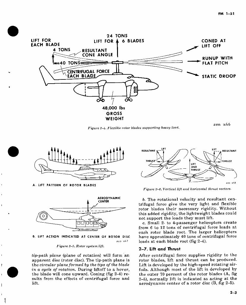
a. At rest, the helicopter blades will droop (fig 2-4) and rest against static stops. When rotated, the blade tips will fly straight out and the
2-2
FM 1-51
LIFT FOR EACH BLADE
4 TONS
24 TONS LIFT FOR i 6 BLADES
RESULTANT CONE ANGLE
40 TONS
CENTRIFUGAL FORCE EACH BLADES
48,000 lbs
GROSS WEIGHT
CONED AT LIFT OFF
RUNUP WITH FLAT PITCH
STATIC DROOP
Figure 2-4. Flexible rotor blades supporting heavy load. avn x46
.
A. LIFT PATTERN OF ROTOR BLADES
LIFT RESULTANT RESULTANT
THRUST THRUST
LIFT AND THRUST
Figure 2-6. Vertical lift and horizontal thrust vectors.
AERODYNAMIC CENTER
<2 □□ □□
B. LIFT ACTION INDICATED AT CENTER OF ROTOR DISC
avn x47
Figure 2-5. Rotor system lift.
tip-path plane (plane of rotation) will form an apparent disc (rotor disc). The tip-path plane is the circular plane formed by the tips of the blade in a cycle of rotation. During liftoff to a hover, the blade will cone upward. Coning (fig 2—4) re- sults from the effects of centrifugal force and lift.
b. The rotational velocity and resultant cen- trifugal force give the very light and flexible rotor blades their necessary rigidity. Without this added rigidity, the lightweight blades could not support the loads they must lift.
c. Small 2- to 4-passenger helicopters create from 6 to 12 tons of centrifugal force loads at each rotor blade root. The larger helicopters have approximately 40 tons of centrifugal force loads at each blade root (fig 2-4).
2—7. Lift and Thrust
After centrifugal force supplies rigidity to the rotor blades, lift and thrust can be produced. Lift is developed by the high-speed rotating air- foils. Although most of the lift is developed by the outer 70 percent of the rotor blades (A, fig 2—5), normally lift is indicated as acting at the aerodynamic center of a rotor disc (B, fig 2-5).
2-3
FM 1-51
- . . V
' vi
I
Figure 2-7. Model airplanes representing the action of rotary wing airfoils. avn x49
2—8. Airfoil Action on Rotary Wing Aircraft B of figure 2-5 shows a vertical lift vector and figure 2-6 shows vertical lift and horizontal thrust vectors.
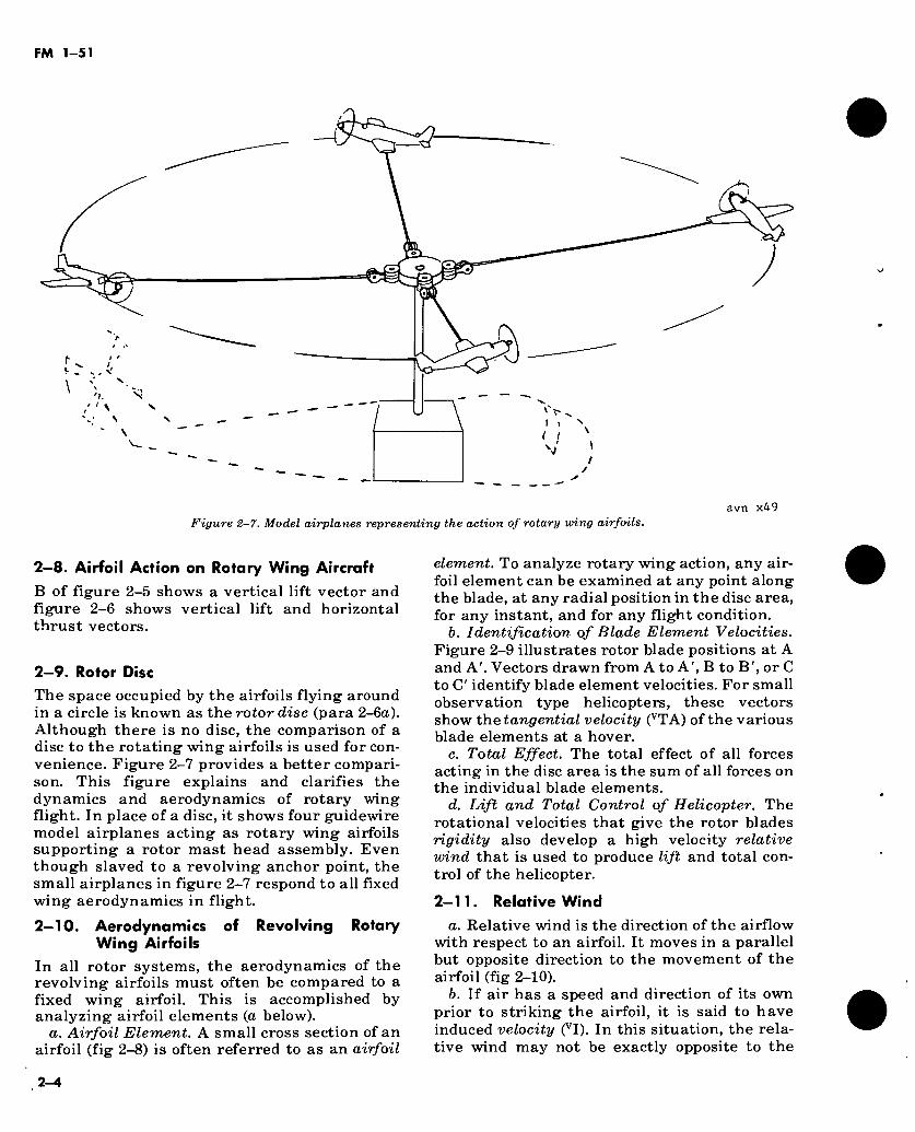
2—9. Rotor Disc The space occupied by the airfoils flying around in a circle is known as the rotor disc (para 2-6a). Although there is no disc, the comparison of a disc to the rotating wing airfoils is used for con- venience. Figure 2-7 provides a better compari- son. This figure explains and clarifies the dynamics and aerodynamics of rotary wing flight. In place of a disc, it shows four guidewire model airplanes acting as rotary wing airfoils supporting a rotor mast head assembly. Even though slaved to a revolving anchor point, the small airplanes in figure 2-7 respond to all fixed wing aerodynamics in flight.
2—10. Aerodynamics of Revolving Rotary Wing Airfoils
In all rotor systems, the aerodynamics of the revolving airfoils must often be compared to a fixed wing airfoil. This is accomplished by analyzing airfoil elements (a below).
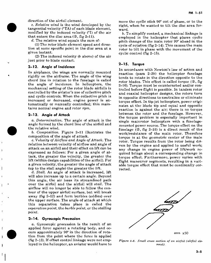
a. Airfoil Element. A small cross section of an airfoil (fig 2-8) is often referred to as an airfoil
element. To analyze rotary wing action, any air- foil element can be examined at any point along the blade, at any radial position in the disc area, for any instant, and for any flight condition.
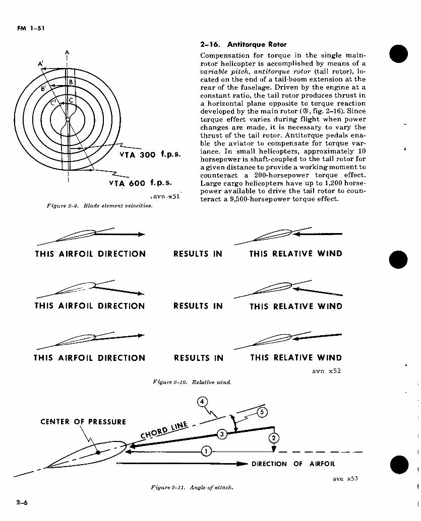
b. Identification of Blade Element Velocities. Figure 2-9 illustrates rotor blade positions at A and A'. Vectors drawn from A to A', B to B', or C to C' identify blade element velocities. For small observation type helicopters, these vectors show the tangential velocity (VTA) of the various blade elements at a hover.
c. Total Effect. The total effect of all forces acting in the disc area is the sum of all forces on the individual blade elements.
d. Lift and Total Control of Helicopter. The rotational velocities that give the rotor blades rigidity also develop a high velocity relative wind that is used to produce lift and total con- trol of the helicopter.
2-11. Relative Wind a. Relative wind is the direction of the airflow
with respect to an airfoil. It moves in a parallel but opposite direction to the movement of the airfoil (fig 2-10).
b. If air has a speed and direction of its own prior to striking the airfoil, it is said to have induced velocity (VI). In this situation, the rela- tive wind may not be exactly opposite to the
2-4
FM 1-51
direction of the airfoil element. c. Relative wind is the wind developed by the
tangential velocity (VTA) of each blade element, modified by the induced velocity (VI) of the air that enters the disc area (CD, fig 2-11).
d. The relative wind equals the sum of- (1) The rotor blade element speed and direc-
tion at some specific point in the disc area at a given instant.
(2) The induced velocity (b above) of the air just prior to blade contact.
2-12. Angle of Incidence In airplanes, the wings are normally mounted rigidly on the airframe. The angle of the wing chord line in relation to the fuselage is called the angle of incidence. In helicopters, the mechanical setting of the rotor blade airfoils is controlled by the aviator’s use of collective pitch and cyclic controls. When the collective pitch is increased or decreased, engine power is au- tomatically or manually controlled; this main- tains normal engine and rotor rpm.
2-13. Angle of Attack a. Determination. The angle of attack is the
angle formed by the chord line of the airfoil and the relative wind.
b. Composition. Figure 2-11 illustrates the composition of the angle of attack.
c. Velocity of Airflow and Angle of Attack. The relation between velocity of airflow and angle of attack on an airfoil and their effect on lift can be expressed as follows: For a given angle of at- tack, the greater the velocity, the greater the lift (within design capabilities of the airfoil). For a given velocity, the greater the angle of attack (up to the stall angle) the greater the lift.
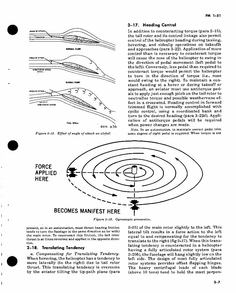
d. Stall. As angle of attack is increased, lift will also increase up to a certain angle. Beyond this angle, the air loses its streamlined path over the airfoil and the airfoil will stall. The airflow will no longer be able to follow the con- tour of the upper airfoil surface, but will break away (fig 2-12) and form burbles (eddies) over the upper surface. The angle of attack at which this separation takes place is called the separation point, the burble point, or th.e stalling point.
2-14. Gyroscopic Precession a. Gyroscopic precession is the result of an
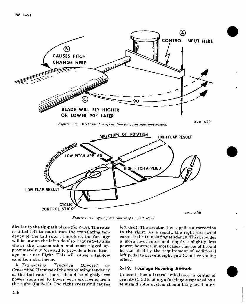
applied force against a rotating body, and oc- curs approximately 90° in the direction of rota- tion from the point where the force is applied (fig 2-13). If offset control linkage were not emp- loyed in the helicopter, an aviator would have to
move the cyclic stick 90° out of phase, or to the right, when he wanted to tilt the disc area for- ward.
b. To simplify control, a mechanical linkage is employed in the helicopter that places cyclic pitch change of the main rotor 90° ahead in the cycle of rotation (fig 2-14). This causes the main rotor to tilt in phase with the movement of the cyclic control (fig 2-15).
2-15. Torque In accordance with Newton’s law of action and reaction (para 2-36) the helicopter fuselage tends to rotate in the direction opposite to the rotor blades. This effect is called torque (©, fig 2-16). Torque must be counteracted and/or con- trolled before flight is possible. In tandem rotor and coaxial helicopter designs, the rotors turn in opposite directions to neutralize or eliminate torque effect. In tip-jet helicopters, power origi- nates at the blade tip and equal and opposite reaction is against the air; there is no torque between the rotor and the fuselage. However, the torque problem is especially important in single mainrotor helicopters with a fuselage- mounted power source. The torque effect on the fuselage (©, fig 2-16) is a direct result of the work/resistance of the main rotor. Therefore torque is at the geometric center of the main rotor. Torque results from the rotor being dri- ven by the engine and applied to useful work; any change in engine power of lift/work re- quired brings about a corresponding change in torque effect. Furthermore, power varies with flight maneuver segments, resulting in a vari- able torque effect that must be continually cor- rected.
avn x50
Figure 2-8. Small cross section of an airfoil (airfoil ele- ment).
2-5
FM 1-51
1/ /
VTA 300 f.p s.
VTA 600 f.p.s.
, avn¡x51 Figure 2-9. Blade element velocities.
2-16. Antitorque Rotor
Compensation for torque in the single main- rotor helicopter is accomplished by means of a variable pitch, antitorque rotor (tail rotor), lo- cated on the end of a tail-boom extension at the rear of the fuselage. Driven by the engine at a constant ratio, the tail rotor produces thrust in a horizontal plane opposite to torque reaction developed by the main rotor (CD, fig. 2-16). Since torque effect varies during flight when power changes are made, it is necessary to vary the thrust of the tail rotor. Antitorque pedals ena- ble the aviator to compensate for torque var- iance. In small helicopters, approximately 10 horsepower is shaft-coupled to the tail rotor for a given distance to provide a working moment to counteract a 200-horsepower torque effect. Large cargo helicopters have up to 1,200 horse- power available to drive the tail rotor to coun- teract a 9,500-horsepower torque effect.
THIS AIRFOIL DIRECTION RESULTS IN THIS RELATIVE WIND
THIS AIRFOIL DIRECTION RESULTS IN THIS RELATIVE WIND
THIS AIRFOIL DIRECTION RESULTS IN THIS RELATIVE WIND
avn x52
Figure 2-10. Relative wind.
CENTER OF PRESSURE
0*9 CY\
© DIRECTION OF AIRFOIL
avn x53
Figure 2-11. Angle of attack.
3-6
FM 1-51
ANGLE OF ATTACK
DIRECTION
NORMAL FLOW
ANGLE OF ATTACK
DIRECTION OF AIRFOIL
BURBLE POINT
ANGLE OF ATTACK
DIRECTION OF AIRFOIL
avn x54
Figure 2-12. Effect of angle of attack on airfoil.
2-17. Heading Control
In addition to counteracting torque (para 2-15), the tail rotor and its control linkage also permit control of the helicopter heading during taxiing, hovering, and sideslip operations on takeoffs and approaches (para 3-22). Application of more control than is necessary to counteract torque will cause the nose of the helicopter to swing in the direction of pedal movement (left pedal to the left). Conversely, less pedal than required to counteract torque would permit the helicopter to turn in the direction of torque (i.e., nose would swing to the right). To maintain a con- stant heading at a hover or during takeoff or approach, an aviator must use antitorque ped- als to apply just enough pitch on the tail rotor to neutralize torque and possible weathervane ef- fect in a crosswind. Heading control in forward trimmed flight is normally accomplished with cyclic control, using a coordinated bank and turn to the desired heading (para 3-22d). Appli- cation of antitorque pedals will be required when power changes are made.
Note. In an autorotation, to maintain correct pedal trim some degree of right pedal is required. When torque is not
FORCE APPLIED HERE
's.
BECOMES MANIFEST HERE Figure 2-13. Gyroscopic precession.
present, as in an autorotation, mast thrust bearing friction tends to turn the fuselage in the same direction as (or with) the main rotor. To counteract this friction, the tail rotor thrust is at times reversed and applied in the opposite direc- tion.
2—18. Translating Tendency
a. Compensating for Translating Tendency. When hovering, the helicopter has a tendency to move laterally (to the right) due to tail rotor thrust. This translating tendency is overcome by the aviator tilting the tip-path plane (para
2-25) of the main rotor slightly to the left. This lateral tilt results in a force action to the left equal to and compensating for the tendency to translate to the right (fig 2-17). When this trans- lating tendency is counteracted in a helicopter having a fully articulated rotor system (para 2-206), the fuselage will hang slightly low on the left side. The design of most fully articulated rotor systems provides offset flapping hinges. The heavy centrifugal loads of each blade (above 10 tons) tend to hold the mast perpen-
2-7
FM 1-51
CONTROL INPUT HERE
CAUSES PITCH
CHANGE HERE
© 90
BLADE WILL FLY HIGHER OR LOWER 90° LATER
Figure 2-1U. Mechanical compensation for gyroscopic prescession.
DjsiSIiS." 0F ■"■0TATI°!L HIGH FLAP RESULT
avn x55
> ¡sAK
& LOW PITCH APPLIED
Tí
HIGH PITCH APPLIED < o~
<,'77 LOW FLAP RESULT
CYCLIC CONTROL STICK
avn x56 Figure 2-15. Cyclic pitch control of tip-path plane.
dicular to the tip-path plane (fig 2-18). The rotor is tilted left to counteract the translating ten- dency of the tail rotor; therefore, the fuselage will be low on the left side also. Figure 2-18 also shows the transmission and mast rigged ap- proximately 3° forward to provide a level fusel- age in cruise flight. This will cause a tail-low condition at a hover.
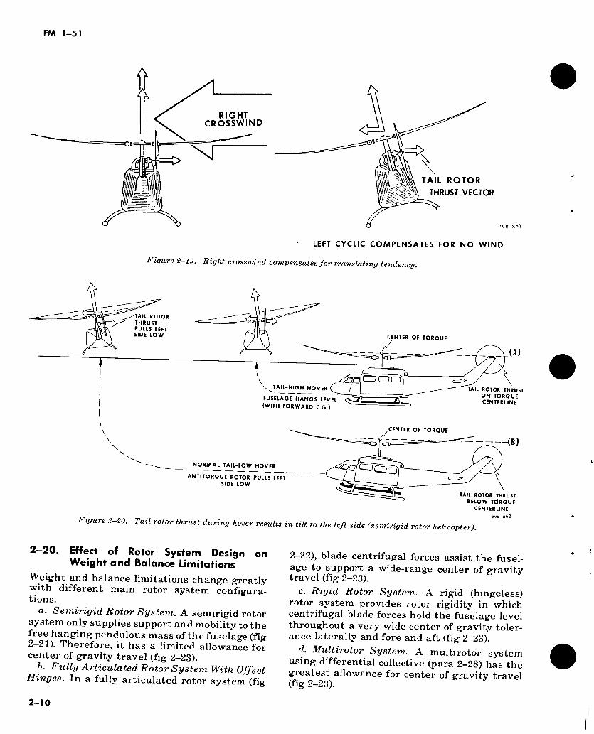
b. Translating Tendency Opposed by Crosswind. Because of the translating tendency of the tail rotor, there should be slightly less power required to hover with crosswind from the right (fig 2-19). The right crosswind causes
left drift. The aviator then applies a correction to the right. As a result, the right crosswind corrects the translating tendency. This provides a more level rotor and requires slightly less power; however, in most cases this benefit could be cancelled by the requirement of additional left pedal to prevent right yaw (weather vaning effect).
2-19. Fuselage Hovering Attitude
Unless it has a lateral unbalance in center of gravity (C.G.) loading, a fuselage suspended by a semirigid rotor system should hang level later-
2-8
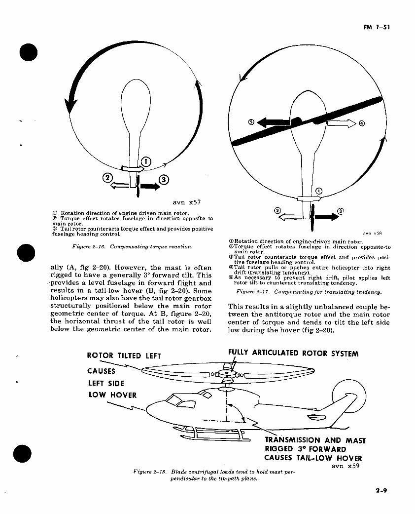
avn x57
© Rotation direction of engine driven main rotor. ® Torque effect rotates fuselage in direction opposite to main rotor. ® Tail rotor counteracts torque effect and provides positive fuselage heading control.
Figure 2-16. Compensating torque reaction.
ally (A, fig 2-20). However, the mast is often rigged to have a generally 3° forward tilt. This
-provides a level fuselage in forward flight and results in a tail-low hover (B, fig 2-20). Some helicopters may also have the tail rotor gearbox structurally positioned below the main rotor geometric center of torque. At B, figure 2-20, the horizontal thrust of the tail rotor is well below the geometric center of the main rotor.
®c avn x58
©Rotation direction of engine-driven main rotor. ©Torque effect rotates fuselage in direction opposite-to
main rotor. ©Tail rotor counteracts torque effect and provides posi-
tive fuselage heading control. ©Tail rotor pulls or pushes entire helicopter into right
drift (translating tendency). ©As necessary to prevent right drift, pilot applies left
rotor tilt to counteract translating tendency.
Figure 2-17. Compensating for translating tendency.
This results in a slightly unbalanced couple be- tween the antitorque rotor and the main rotor center of torque and tends to tilt the left side low during the hover (fig 2-20).
ROTOR TILTED LEFT
CAUSES
LEFT SIDE
LOW HOVER
FULLY ARTICULATED ROTOR SYSTEM
30 or~
O ¿=3
TRANSMISSION AND MAST RIGGED 3° FORWARD CAUSES TAIL-LOW HOVER
avn x59 Figure 2-18. Blade centrifugal loads tend to hold mast per-
pendicular to the tip-path plane.
2-9
FM 1-51
ft A
RIGHT CROSSWIND
=£>
TAIL ROTOR
THRUST VECTOR
LEFT CYCLIC COMPENSATES FOR NO WIND
Figure 2-19. Right crosswind compensates for translating tendency.
TAIL BOTOR
THRUST PULLS LEFT SIDE LOW CENTER OF TORQUE
/
\ CDOO £70 \. TAIL-HIGH HOVER
FUSELAGE HANGS LEVEL <S5TI
(WITH FORWARD C.G.)
TAIL ROTOR THRUST
ON TORÖUE CENTERLINE
\
CENTER OF TORQUE
NORMAL TAIL-LOW HOVER
ANTITOROUE ROTOR PULLS LEFT
SIDE LOW
CLP
¿On
-(B)
Figure 2-20. Tail rotor thrust during hover results in tilt to the left side (semirigid rotor helicopter)
TAIL ROTOR THRUST
BELOW TORQUE
CENTERLINE
avn x62
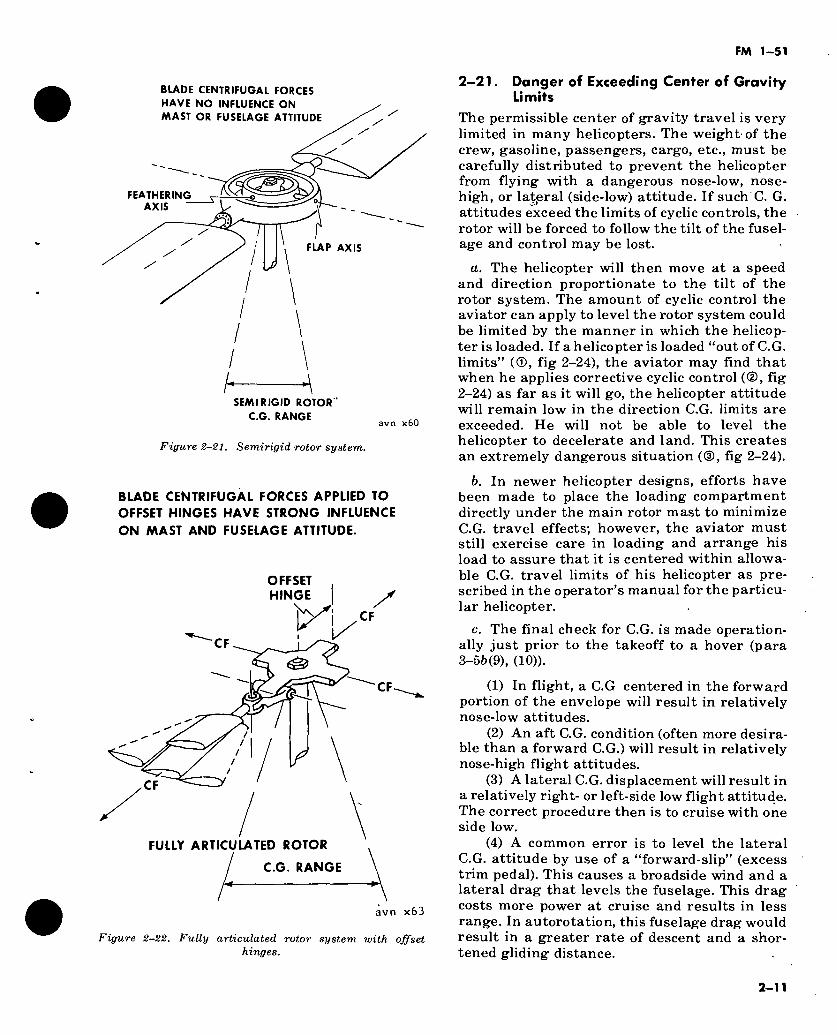
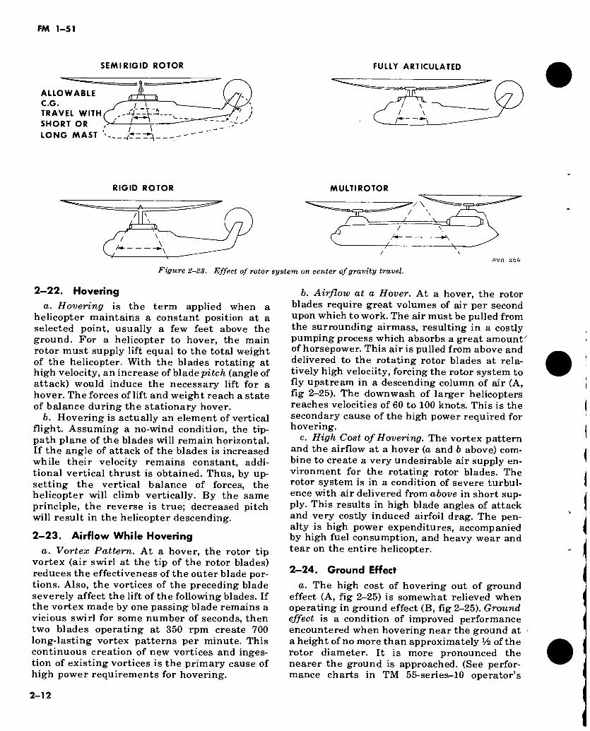
2 20. Effect of Rotor System Design on Weight and Balance Limitations
Weight and balance limitations change greatly with different main rotor system configura- tions.
a. Semirigid Rotor System. A semirigid rotor system only supplies support and mobility to the free hanging pendulous mass of the fuselage (fig 2~21). Therefore, it has a limited allowance for center of gravity travel (fig 2-23).
b. Fully Articulated Rotor System With Offset Hinges. In a fully articulated rotor system (fig
2-22), blade centrifugal forces assist the fusel- age to support a wide-range center of gravity travel (fig 2-23).
c. Rigid Rotor System. A rigid (hingeless) rotor system provides rotor rigidity in which centrifugal blade forces hold the fuselage level throughout a very wide center of gravity toler- ance laterally and fore and aft (fig 2-23).
d. Multirotor System. A multirotor system using differential collective (para 2-28) has the greatest allowance for center of gravity travel (fig 2-23).
2-10
FM 1-51
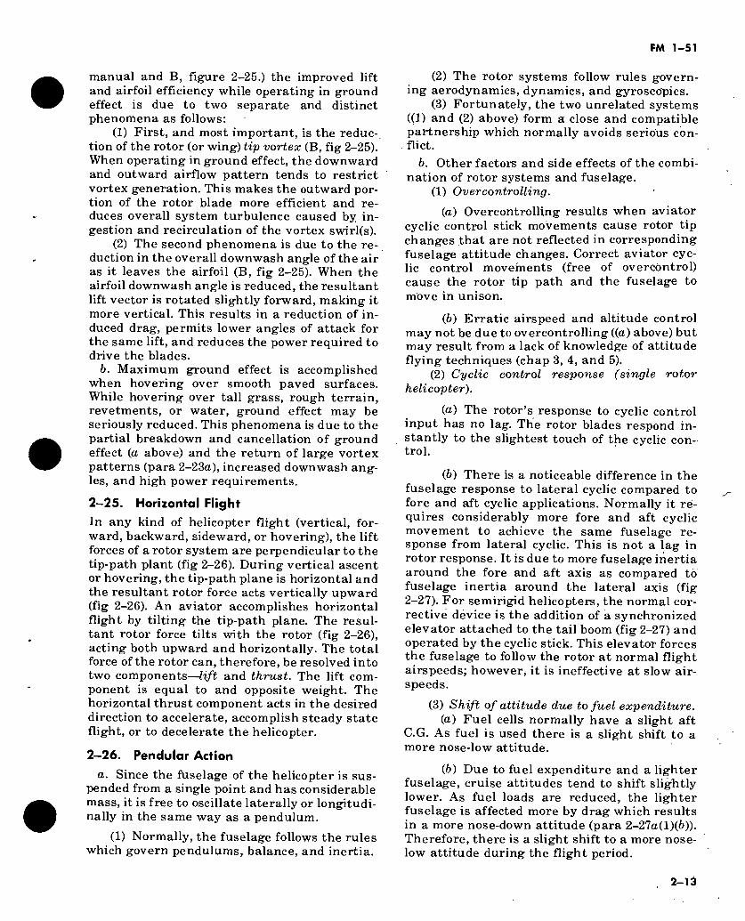
BLADE CENTRIFUGAL FORCES HAVE NO INFLUENCE ON MAST OR FUSELAGE ATTITUDE
FEATHERING AXIS
FLAP AXIS
\J
■A SEMI RIGID ROTOR
G. RANGE avn x60
Figure 2-21. Semirigid rotor system.
BLADE CENTRIFUGAL FORCES APPLIED TO OFFSET HINGES HAVE STRONG INFLUENCE
ON MAST AND FUSELAGE ATTITUDE.
OFFSET HINGE I yf
|X¡ -«
FULLY ARTICULATED ROTOR
C.G. RANGE
x63
Figure 2-22. Fully articulated rotor system with offset hinges.
2-21. Danger of Exceeding Center of Gravity Limits
The permissible center of gravity travel is very limited in many helicopters. The weight of the crew, gasoline, passengers, cargo, etc., must be carefully distributed to prevent the helicopter from flying with a dangerous nose-low, nose- high, or lateral (side-low) attitude. If such C. G. attitudes exceed the limits of cyclic controls, the rotor will be forced to follow the tilt of the fusel- age and control may be lost.
a. The helicopter will then move at a speed and direction proportionate to the tilt of the rotor system. The amount of cyclic control the aviator can apply to level the rotor system could be limited by the manner in which the helicop- ter is loaded. If a helicopter is loaded “out of C.G. limits” (©, fig 2-24), the aviator may find that when he applies corrective cyclic control (©, fig 2- 24) as far as it will go, the helicopter attitude will remain low in the direction C.G. limits are exceeded. He will not be able to level the helicopter to decelerate and land. This creates an extremely dangerous situation (®, fig 2-24).
b. In newer helicopter designs, efforts have been made to place the loading compartment directly under the main rotor mast to minimize C.G. travel effects; however, the aviator must still exercise care in loading and arrange his load to assure that it is centered within allowa- ble C.G. travel limits of his helicopter as pre- scribed in the operator’s manual for the particu- lar helicopter.
c. The final check for C.G. is made operation- ally just prior to the takeoff to a hover (para 3- 56(9), (10)).
(1) In flight, a C.G centered in the forward portion of the envelope will result in relatively nose-low attitudes.
(2) An aft C.G. condition (often more desira- ble than a forward C.G.) will result in relatively nose-high flight attitudes.
(3) A lateral C.G. displacement will result in a relatively right- or left-side low flight attitude. The correct procedure then is to cruise with one side low.
(4) A common error is to level the lateral C.G. attitude by use of a “forward-slip” (excess trim pedal). This causes a broadside wind and a lateral drag that levels the fuselage. This drag costs more power at cruise and results in less range. In autorotation, this fuselage drag would result in a greater rate of descent and a shor- tened gliding distance.
2-11
FM 1-51
SEMIRIGID ROTOR FULLY ARTICULATED
ALLOWABLE C.G. TRAVEL WITH SHORT OR LONG MAST
£2
r--~\
RIGID ROTOR MULTIROTOR
avn x64
Figure 2-23. Effect of rotor system on center of gravity travel.
2—22. Hovering
a. Hovering is the term applied when a helicopter maintains a constant position at a selected point, usually a few feet above the ground. For a helicopter to hover, the main rotor must supply lift equal to the total weight of the helicopter. With the blades rotating at high velocity, an increase of blade (angle of attack) would induce the necessary lift for a hover. The forces of lift and weight reach a state of balance during the stationary hover.
b. Hovering is actually an element of vertical flight. Assuming a no-wind condition, the tip- path plane of the blades will remain horizontal. If the angle of attack of the blades is increased while their velocity remains constant, addi- tional vertical thrust is obtained. Thus, by up- setting the vertical balance of forces, the helicopter will climb vertically. By the same principle, the reverse is true; decreased pitch will result in the helicopter descending.
2—23. Airflow While Hovering
a. Vortex Pattern. At a hover, the rotor tip vortex (air swirl at the tip of the rotor blades) reduces the effectiveness of the outer blade por- tions. Also, the vortices of the preceding blade severely affect the lift of the following blades. If the vortex made by one passing blade remains a vicious swirl for some number of seconds, then two blades operating at 350 rpm create 700 long-lasting vortex patterns per minute. This continuous creation of new vortices and inges- tion of existing vortices is the primary cause of high power requirements for hovering.
b. Airflow at a Hover. At a hover, the rotor blades require great volumes of air per second upon which to work. The air must be pulled from the surrounding airmass, resulting in a costly pumping process which absorbs a great amount^ of horsepower. This air is pulled from above and delivered to the rotating rotor blades at rela- tively high velociity, forcing the rotor system to fly upstream in a descending column of air (A, fig 2-25). The downwash of larger helicopters reaches velocities of 60 to 100 knots. This is the secondary cause of the high power required for hovering.
c. High Cost of Hovering. The vortex pattern and the airflow at a hover (a and b above) com- bine to create a very undesirable air supply en- vironment for the rotating rotor blades. The rotor system is in a condition of severe turbul- ence with air delivered from above in short sup- ply. This results in high blade angles of attack and very costly induced airfoil drag. The pen- alty is high power expenditures, accompanied by high fuel consumption, and heavy wear and tear on the entire helicopter.
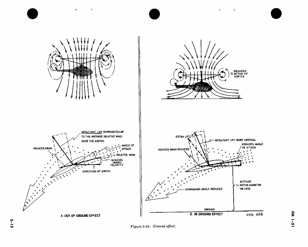
2-24. Ground Effect
a. The high cost of hovering out of ground effect (A, fig 2-25) is somewhat relieved when operating in ground effect (B, fig 2-25). Ground effect is a condition of improved performance encountered when hovering near the ground at a height of no more than approximately Vz of the rotor diameter. It is more pronounced the nearer the ground is approached. (See perfor- mance charts in TM 55-series-10 operator’s
2-12
FM 1-51
manual and B, figure 2-25.) the improved lift and airfoil efficiency while operating in ground effect is due to two separate and distinct phenomena as follows:
(1) First, and most important, is the reduc-, tion of the rotor (or wing) tip vortex (B, fig 2-25). When operating in ground effect, the downward and outward airflow pattern tends to restrict vortex generation. This makes the outward por- tion of the rotor blade more efficient and re- duces overall system turbulence caused by in- gestion and recirculation of the vortex swirl(s).
(2) The second phenomena is due to the re- duction in the overall downwash angle of the air as it leaves the airfoil (B, fig 2-25). When the airfoil downwash angle is reduced, the resultant lift vector is rotated slightly forward, making it more vertical. This results in a reduction of in- duced drag, permits lower angles of attack for the same lift, and reduces the power required to drive the blades.
b. Maximum ground effect is accomplished when hovering over smooth paved surfaces. While hovering over tall grass, rough terrain, revetments, or water, ground effect may be seriously reduced. This phenomena is due to the partial breakdown and cancellation of ground effect (a above) and the return of large vortex patterns (para 2-23a), increased downwash ang- les, and high power requirements.
2-25. Horizontal Flight
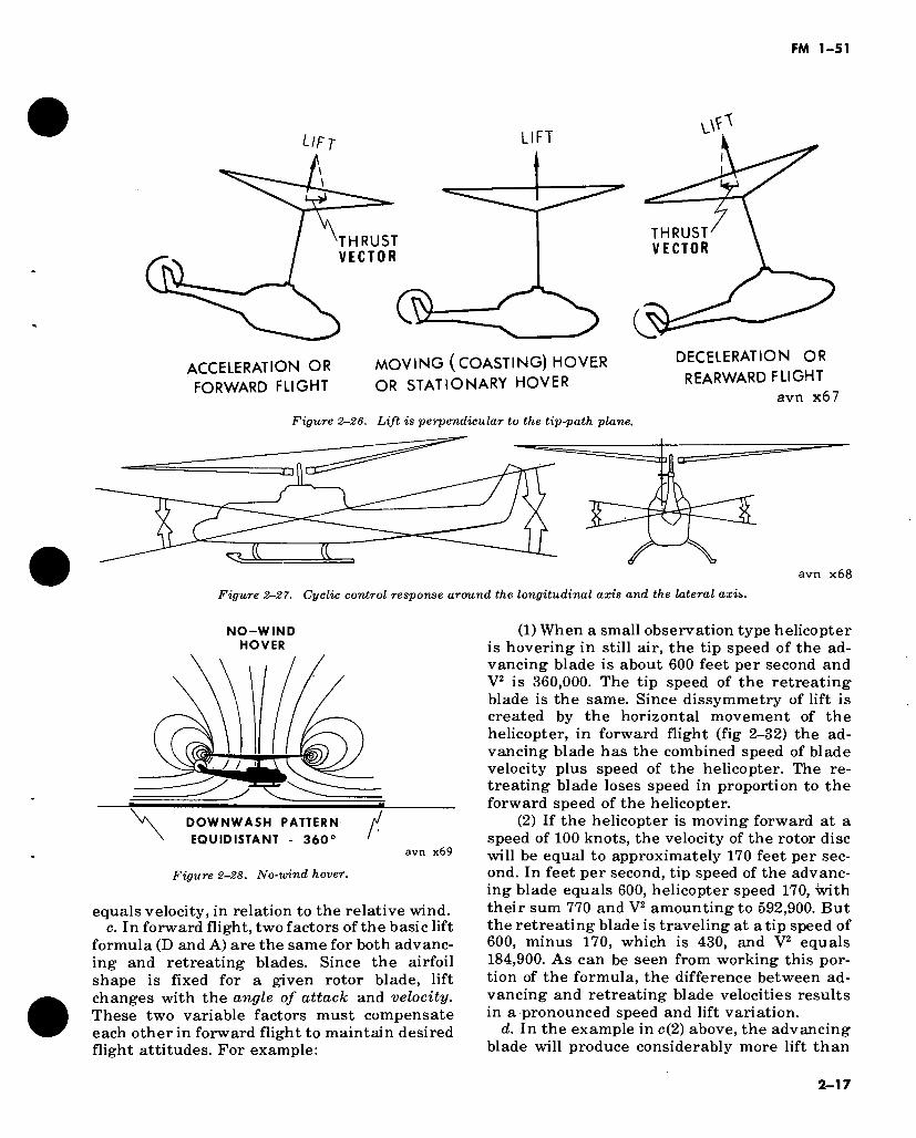
In any kind of helicopter flight (vertical, for- ward, backward, sideward, or hovering), the lift forces of a rotor system are perpendicular to the tip-path plant (fig 2-26). During vertical ascent or hovering, the tip-path plane is horizontal and the resultant rotor force acts vertically upward (fig 2-26). An aviator accomplishes horizontal flight by tilting the tip-path plane. The resul- tant rotor force tilts with the rotor (fig 2-26), acting both upward and horizontally. The total force of the rotor can, therefore, be resolved into two components—lift and thrust. The lift com- ponent is equal to and opposite weight. The horizontal thrust component acts in the desired direction to accelerate, accomplish steady state flight, or to decelerate the helicopter.
2-26. Pendular Action
a. Since the fuselage of the helicopter is sus- pended from a single point and has considerable mass, it is free to oscillate laterally or longitudi- nally in the same way as a pendulum.
(1) Normally, the fuselage follows the rules which govern pendulums, balance, and inertia.
(2) The rotor systems follow rules govern- ing aerodynamics, dynamics, and gyroscopics.
(3) Fortunately, the two unrelated systems ((1) and (2) above) form a close and compatible partnership which normally avoids serious con- flict.
b. Other factors and side effects of the combi- nation of rotor systems and fuselage.
(1) Overcontrolling.
(а) Overcontrolling results when aviator cyclic control stick movements cause rotor tip changes that are not reflected in corresponding fuselage attitude changes. Correct aviator cyc- lic control movements (free of overcöntrol) cause the rotor tip path and the fuselagè to move in unison.
(б) Erratic airspeed and altitude control may not be due to overcontrolling ((a) above) but may result from a lack of knowledge of attitude flying techniques (chap 3, 4, and 5).
(2) Cyclic control response (single rotor helicopter).
(а) The rotor’s response to cyclic control input has no lag. The rotor blades respond in- stantly to the slightest touch of the cyclic con- trol.
(б) There is a noticeable difference in the fuselage response to lateral cyclic compared to fore and aft cyclic applications. Normally it ré- quires considerably more fore and aft cyclic movement to achieve the same fuselage re- sponse from lateral cyclic. This is not a lag in rotor response. It is due to more fuselage inertia around the fore and aft axis as compared to fuselage inertia around the lateral axis (fig 2-27). For semirigid helicopters, the normal cor- rective device is the addition of a synchronized elevator attached to the tail boom (fig 2-27) and operated by the cyclic stick. This elevator forces the fuselage to follow the rotor at normal flight airspeeds; however, it is ineffective at slow air- speeds.
(3) Shift of attitude due to fuel expenditure. (а) Fuel cells normally have a slight aft
C.G. As fuel is used there is a slight shift to a more nose-low attitude.
(б) Due to fuel expenditure and a lighter fuselage, cruise attitudes tend to shift sliglitly lower. As fuel loads are reduced, the lighter fuselage is affected more by drag which results in a more nose-down attitude (para 2-27a(l)(6)). Therefore, there is a slight shift to a more nose- low attitude during the flight period.
2-13
FM 1-51
(=) +
CYCLIC CONTROL STICK AGAINST CTX REAR STOPS
SHIFT OF NORMAL C.G.
J.
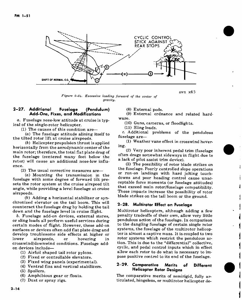
Figure 2-2U- Excessive loading forward of the center of gravity.
avn x65
2—27. Additional Fuselage (Pendulum) Add-Ons, Fixes, and Modifications
a. Fuselage nose-low attitude at cruise is typ- ical of the single-rotor helicopter.
(1) The causes of this condition are— (а) The fuselage attitude alining itself to
the tilted rotor lift at cruise airspeeds. (б) Helicopter propulsion thrust is applied
horizontally from the aerodynamic center of the main rotor; therefore, the total flat plate drag of the fuselage (centered many feet below the rotor) will cause an additional nose-low influ- ence.
(2) The usual corrective measures are— (а) Mounting the transmission in the
fuselage with some degree of forward tilt pre- sets the rotor system at the cruise airspeed tilt angle, while providing a level fuselage at cruise airspeeds.
(б) Adding a horizontal stabilizer or syn- chronized elevator on the tail boom. This will counteract the fuselage drag by holding the tail down and the fuselage level in cruise flight.
b. Fuselage add-on devices, external stores, or sling loads all perform useful services during certain modes of flight. However, these add-on surfaces or devices often add flat plate drag and develop troublesome side effects at higher or lower airspeeds, or hovering in crosswind/downwind conditions. Fuselage add- on devices include—
(1) Airfoil shaped tail rotor pylons. (2) Fixed or controllable elevators. (3) Fixed wing panels (experimental). (4) Ventral fins and vertical stabilizers. (5) Spoilers. (6) Amphibious gear or floats. (7) Dust or spray rigs.
(8) External pods. (9) External ordnance and related hard-
ware. (10) Guns, cameras, or floodlights. (11) Sling loads.
c. Additional problems of the pendulous fuselage are—
(1) Weather vane effect in crosswind hover- ing.
(2) Very poor inherent pedal trim (fuselage often drags somewhat sideways in flight due to a lack of pilot assist trim device).
(3) The possibility of rotor blade strikes on the fuselage. Poorly controlled slope operations or run-on landings with hard jolting touch- downs and poor heading control cause unac- ceptable force moments (or fuselage attitudes) that exceed main rotor/fuselage compatibility. These impacts increase the possibility of rotor blade strikes on the tail boom or the ground.
2—28. Multirotor Effect on Fuselage
Multirotor helicopters, although adding a few penalty tradeoffs of their own, allow very little pendulous action of the fuselage. In comparison to the dangling fuselage of certain single rotor systems, the fuselage of the multirotor helicop- ter is almost a captive mass. It is coupled to two rotor systems which restrict the pendulous ac- tion. This is due to the “differential” collective, cyclic, and pedal control inputs which in effect allow each rotor to do what is necessary to im- pose positive control to its end of the fuselage.
2-29. Comparative Merits of Different Helicopter Rotor Designs
The comparative merits of semirigid, fully ar- ticulated, hingeless, or multirotor helicopter de-
2-14
\ \ \ \ W / / / ^ A W Util/A
1% fr*¡ ?IA ?
INDUCED DRAG
RESULTANT LIET PERPENDICULAR
TO THE AVERAGE RELATIVE WIND
OVER THE AIRFOIL
ANGLE OF
• ' ATTACK ° •
RELATIVE WIND
INDUCED (WIND)
VELOCITY *
DIRECTION OF AIRFOIL
A OUT OF GROUND EFFECT
w
REDUCED ROTOR TIP VORTEX
RESULTANT LIFT MORE VERTICAL
REDUCED ANGLE
OF ATTACK
1
^ \ EXTRA LIFT
\ W \J
INDUCED DRAG REDUCED
* V
o O
O o
V • a o
ALTITUDE
► 'h ROTOR DIAMETER
OR LESS
o o
DOWNWASH ANGLE REDUCED
GROUND
B. IN GROUND EFFECT avn x66
Figure 2-25. Ground effect.
FM
1-5
1
FM 1-51
signs will be argued ad infinitum. The aviator must accept them as they are. Knowing the op- erational and flight characteristics of the vari- ous combinations of components will be most rewarding, but usually require constant effort and study on the part of every aviator.
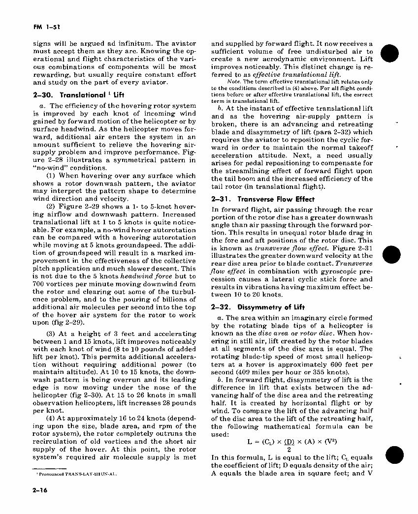
2—30. Translational 1 Lift a. The efficiency of the hovering rotor system
is improved by each knot of incoming wind gained by forward motion of the helicopter or by surface headwind. As the helicopter moves for- ward, additional air enters the system in an amount sufficient to relieve the hovering air- supply problem and improve performance. Fig- ure 2-28 illustrates a symmetrical pattern in “no-wind” conditions.
(1) When hovering over any surface which shows a rotor downwash pattern, the aviator may interpret the pattern shape to determine wind direction and velocity.
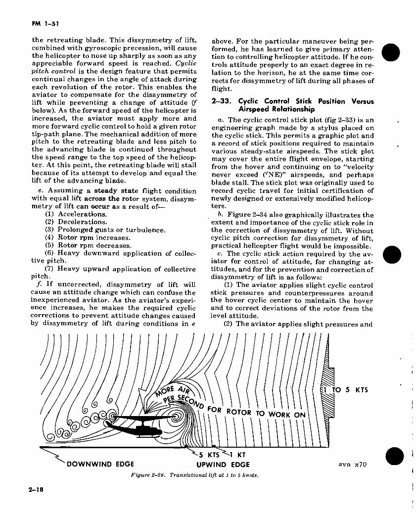
(2) Figure 2-29 shows a 1- to 5-knot hover- ing airflow and downwash pattern. Increased translational lift at 1 to 5 knots is quite notice- able. For example, a no-wind hover autorotation can be compared with a hovering autorotation while moving at 5 knots groundspeed. The addi- tion of groundspeed will result in a marked im- provement in the effectiveness of the collective pitch application and much slower descent. This is not due to the 5 knots headwind force but to 700 vortices per minute moving downwind from the rotor and clearing out some of the turbul- ence problem, and to the pouring of billions of additional air molecules per second into the top of the hover air system for the rotor to work upon (fig 2-29).
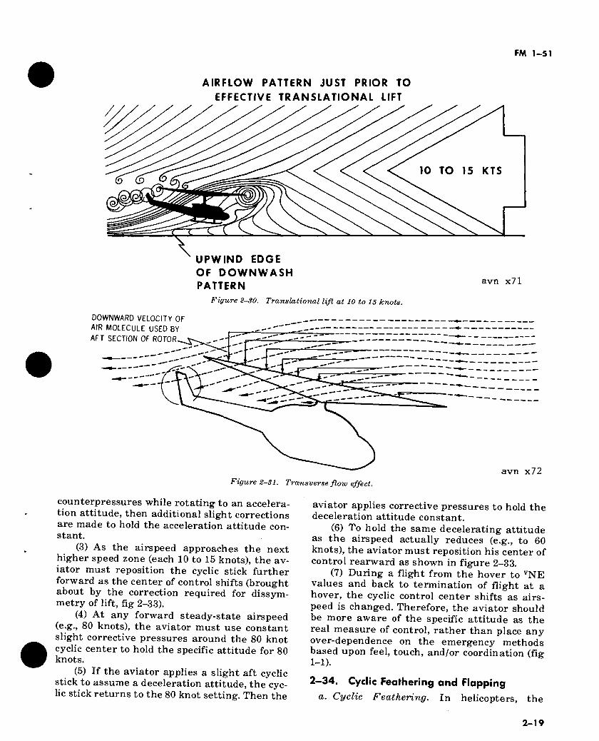
(3) At a height of 3 feet and accelerating between 1 and 15 knots, lift improves noticeably with each knot of wind (8 to 10 pounds of added lift per knot). This permits additional accelera- tion without requiring additional power (to maintain altitude). At 10 to 15 knots, the down- wash pattern is being overrun and its leading edge is now moving under the nose of the helicopter (fig 2-30). At 15 to 26 knots in small observation helicopters, lift increases 28 pounds per knot.
(4) At approximately 16 to 24 knots (depend- ing upon the size, blade area, and rpm of the rotor system), the rotor completely outruns the recirculation of old vortices and the short air supply of the hover. At this point, the rotor system’s required air molecule supply is met
1 Pronounced TRANS-LAY-SH UN-AL.
and supplied by forward flight. It now receives a sufficient volume of free undisturbed air to create a new aerodynamic environment. Lift improves noticeably. This distinct change is re- ferred to as effective translational lift.
Note. The term effective translational lift relates only to the conditions described in (4) above. For all flight condi- tions before or after effective translational lift, the correct term is translational lift.
b. At the instant of effective translational lift and as the hovering air-supply pattern is broken, there is an advancing and retreating blade and dissymmetry of lift (para 2-32) which requires the aviator to reposition the cyclic for- ward in order to maintain the normal takeoff acceleration attitude. Next, a need usually arises for pedal repositioning to compensate for the streamlining effect of forward flight upon the tail boom and the increased efficiency of the tail rotor (in translational flight).
2—31. Transverse Flow Effect In forward flight, air passing through the rear portion of the rotor disc has a greater downwash angle than air passing through the forward por- tion. This results in unequal rotor blade drag in the fore and aft positions of the rotor disc. This is known as transverse flow effect. Figure 2-31 illustrates the greater downward velocity at the rear disc area prior to blade contact. Transverse flow effect in combination with gyroscopic pre- cession causes a lateral cyclic stick force and results in vibrations having maximum effect be- tween 10 to 20 knots.
2—32. Dissymmetry of Lift a. The area within an imaginary circle formed
by the rotating blade tips of a helicopter is known as the disc area or rotor disc. When hov- ering in still air, lift created by the rotor blades at all segments of the disc area is equal. The rotating blade-tip speed of most small helicop- ters at a hover is approximately 600 feet per second (409 miles per hour or 355 knots).
b. In forward flight, dissymmetry of lift is the difference in lift that exists between the ad- vancing half of the disc area and the retreating half. It is created by horizontal flight or by wind. To compare the lift of the advancing half of the disc area to the lift of the retreating half, the following mathematical formula can be used:
L = (CL) x (D) x (A) x (V2) 2
In this formula, L is equal to the lift; CL equals the coefficient of lift; D equals density of the air; A equals the blade area in square feet; and V
2-16
FM 1-51
LIFT UFT
y THRUST VECTOR THRUST
VECTOR
ACCELERATION OR
FORWARD FLIGHT
MOVING (COASTING) HOVER
OR STATIONARY HOVER
DECELERATION OR
REARWARD FLIGHT
Figure 2-26. Lift is perpendicular to the tip-path plane.
X avn x68
Figure 2-27. Cyclic control response around the longitudinal axis and the lateral axis.
NO-WIND HOVER
J /
DOWNWASH PATTERN EQUIDISTANT - 360°
avn x69
Figure 2-28. No-wind hover.
equals velocity, in relation to the relative wind. c. In forward flight, two factors of the basic lift
formula (D and A) are the same for both advanc- ing and retreating blades. Since the airfoil shape is fixed for a given rotor blade, lift changes with the angle of attack and velocity. These two variable factors must compensate each other in forward flight to maintain desired flight attitudes. For example:
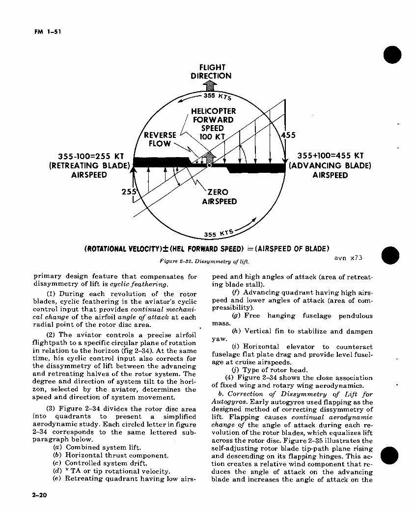
(1) When a small observation type helicopter is hovering in still air, the tip speed of the ad- vancing blade is about 600 feet per second and V2 is 360,000. The tip speed of the retreating blade is the same. Since dissymmetry of lift is created by the horizontal movement of the helicopter, in forward flight (fig 2-32) the ad- vancing blade has the combined speed of blade velocity plus speed of the helicopter. The re- treating blade loses speed in proportion to the forward speed of the helicopter.
(2) If the helicopter is moving forward at a speed of 100 knots, the velocity of the rotor disc will be equal to approximately 170 feet per sec- ond. In feet per second, tip speed of the advanc- ing blade equals 600, helicopter speed 170, with their sum 770 and V2 amounting to 592,900. But the retreating blade is traveling at a tip speed of 600, minus 170, which is 430, and V2 equals 184,900. As can be seen from working this por- tion of the formula, the difference between ad- vancing and retreating blade velocities results in a pronounced speed and lift variation.
d. In the example in c(2) above, the advancing blade will produce considerably more lift than
2-17
FM 1-51
the retreating blade. This dissymmetry of lift, combined with gyroscopic precession, will cause the helicopter to nose up sharply as soon as any appreciable forward speed is reached. Cyclic pitch control is the design feature that permits continual changes in the angle of attack during each revolution of the rotor. This enables the aviator to compensate for the dissymmetry of lift while preventing a change of attitude (f below). As the forward speed of the helicopter is increased, the aviator must apply more and more forward cyclic control to hold a given rotor tip-path plane. The mechanical addition of more pitch to the retreating blade and less pitch to the advancing blade is continued throughout the speed range to the top speed of the helicop- ter. At this point, the retreating blade will stall because of its attempt to develop and equal the lift of the advancing blade.
e. Assuming a steady state flight condition with equal lift across the rotor system, dissym- metry of lift can occur as a result of—
(1) Accelerations. (2) Decelerations. (3) Prolonged gusts or turbulence. (4) Rotor rpm increases. (5) Rotor rpm decreases. (6) Heavy downward application of collec-
tive pitch. (7) Heavy upward application of collective
pitch. /. If uncorrected, dissymmetry of lift will
cause an attitude change which can confuse the inexperienced aviator. As the aviator’s experi- ence increases, he makes the required cyclic corrections to prevent attitude changes caused by dissymmetry of lift during conditions in e
above. For the particular maneuver being per- formed, he has learned to give primary atten- tion to controlling helicopter attitude. If he con- trols attitude properly to an exact degree in re- lation to the horizon, he at the same time cor- rects for dissymmetry of lift during all phases of flight.
2—33. Cyclic Control Stick Position Versus Airspeed Relationship
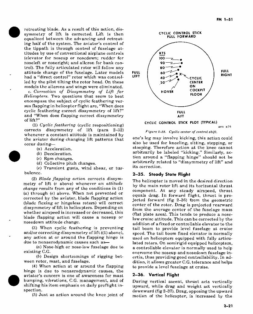
a. The cyclic control stick plot (fig 2-33) is an engineering graph made by a stylus placed on the cyclic stick. This permits a graphic plot and a record of stick positions required to maintain various steady-state airspeeds. The stick plot may cover the entire flight envelope, starting from the hover and continuing on to “velocity never exceed (VNE)” airspeeds, and perhaps blade stall. The stick plot was originally used to record cyclic travel for initial certification of newly designed or extensively modified helicop- ters.
b. Figure 2-34 also graphically illustrates the extent and importance of the cyclic stick role in the correction of dissymmetry of lift. Without cyclic pitch correction for dissymmetry of lift, practical helicopter flight would be impossible.
c. The cyclic stick action required by the av- iator for control of attitude, for changing at- titudes, and for the prevention and correction of dissymmetry of lift is as follows:
(1) The aviator applies slight cyclic control stick pressures and counterpressures around the hover cyclic center to maintain the hover and to correct deviations of the rotor from the level attitude.
(2) The aviator applies slight pressures and
0*E A/È Î1 TO SfC 9«
OR ROTOR TO WORK ON m KTS
DOWNWIND EDGE 5 KTS^-l KT
UPWIND EDGE avn x70
Figure 2-29. Translational lift at 1 to 5 knots.
2-18
FM 1-51
AIRFLOW PATTERN JUST PRIOR TO
EFFECTIVE TRANSLATIONAL LIFT
10 TO 15 KTS
UPWIND EDGE
OF DOWNWASH PATTERN
Figure 2-30. Translational lift at 10 to 15 knots.
avn x71
DOWNWARD VELOCITY OF AIR MOLECULE USED BY AFT SECTION OF ROTOR , a
avn x72 Figure 2—31. Transverse flow effect.
counterpressures while rotating to an accelera- tion attitude, then additional slight corrections are made to hold the acceleration attitude con- stant.
(3) As the airspeed approaches the next higher speed zone (each 10 to 15 knots), the av- iator must reposition the cyclic stick further forward as the center of control shifts (brought about by the correction required for dissym- metry of lift, fig 2-33).
(4) At any forward steady-state airspeed (e.g., 80 knots), the aviator must use constant slight corrective pressures around the 80 knot cyclic center to hold the specific attitude for 80 knots.
(5) If the aviator applies a slight aft cyclic stick to assume a deceleration attitude, the cyc- lic stick returns to the 80 knot setting. Then the
aviator applies corrective pressures to hold the deceleration attitude constant.
(6) To hold the same decelerating attitude as the airspeed actually reduces (e.g., to 60 knots), the aviator must reposition his center of control rearward as shown in figure 2-33.
(7) During a flight from the hover to VNE values and back to termination of flight at a hover, the cyclic control center shifts as airs- peed is changed. Therefore, the aviator should be more aware of the specific attitude as the real measure of control, rather than place any over-dependence on the emergency methods based upon feel, touch, and/or coordination (fig 1-1).
2-34. Cyclic Feathering and Flapping
a. Cyclic Feathering. In helicopters, the
2-19
FM 1-51
FLIGHT DIRECTION
355-100=255 KT (RETREATING BLADE)
AIRSPEED
255
355 «Ts
HELICOPTER FORWARD
SPEED \ 100 KT/^ REVERSE
FLOW '
ZERO AIRSPEED
355
455
355+100=455 KT
(ADVANCING BLADE) AIRSPEED
(ROTATIONAL VEL0CITY)±(HEL FORWARD SPEED) = (AIRSPEED OF BLADE)
Figure 2-32. Dissymmetry of lift. avn x73
primary design feature that compensates for dissymmetry of lift is cyclic feathering.
(1) During each revolution of the rotor blades, cyclic feathering is the aviator’s cyclic control input that provides continual mechani- cal change of the airfoil angle of attach at each radial point of the rotor disc area.
(2) The aviator controls a precise airfoil flightpath to a specific circular plane of rotation in relation to the horizon (fig 2-34). At the same time, his cyclic control input also corrects for the dissymmetry of lift between the advancing and retreating halves of the rotor system. The degree and direction of system tilt to the hori- zon, selected by the aviator, determines the speed and direction of system movement.
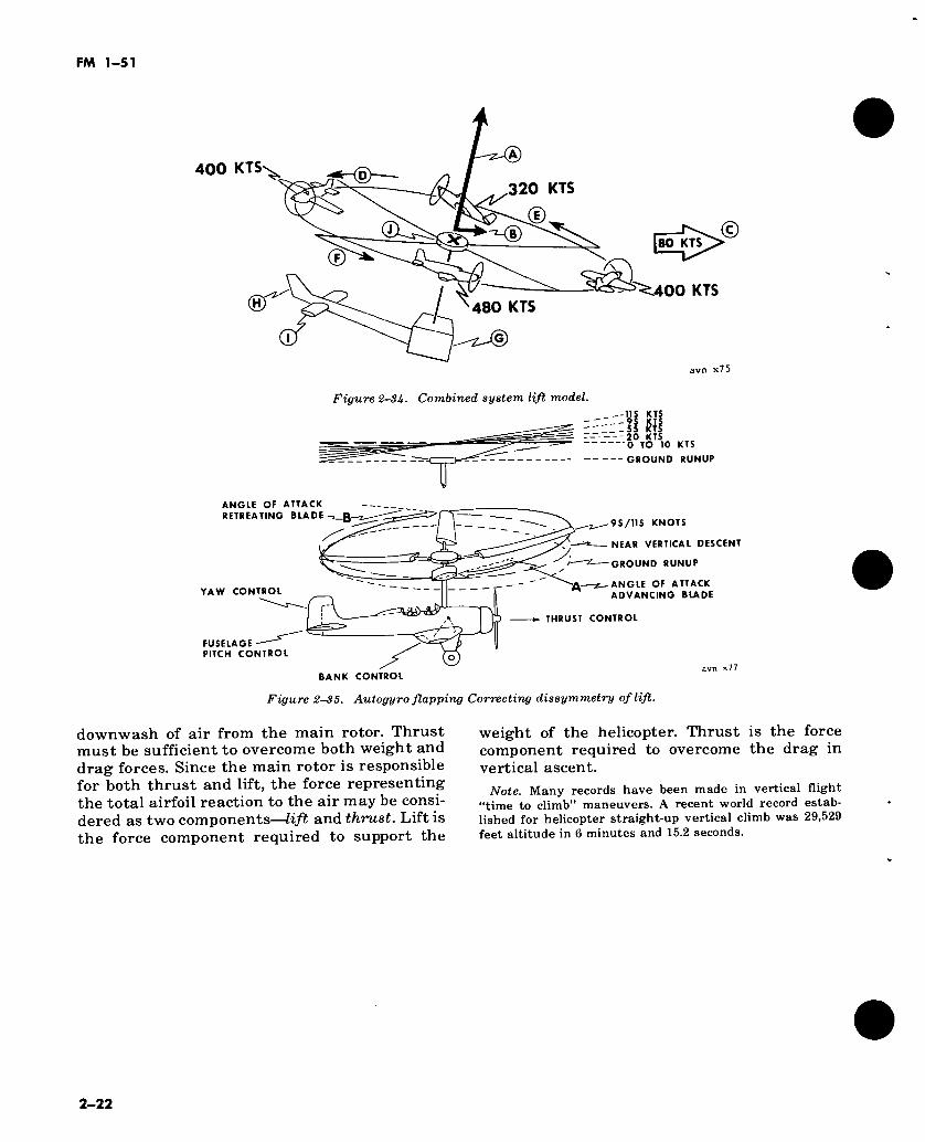
(3) Figure 2-34 divides the rotor disc area into quadrants to present a simplified aerodynamic study. Each circled letter in figure 2-34 corresponds to the same lettered sub- paragraph below.
(a) Combined system lift. (ft) Horizontal thrust component. (c) Controlled system drift. (d) v TA or tip rotational velocity. (e) Retreating quadrant having low airs-
peed and high angles of attack (area of retreat- ing blade stall).
(/) Advancing quadrant having high airs- peed and lower angles of attack (area of com- pressibility).
ig) Free hanging fuselage pendulous mass.
Qi) Vertical fin to stabilize and dampen yaw.
(i) Horizontal elevator to counteract fuselage flat plate drag and provide level fusel- age at cruise airspeeds.
(j) Type of rotor head. (4) Figure 2-34 shows the close association
of fixed wing and rotary wing aerodynamics. ft. Correction of Dissymmetry of Lift for
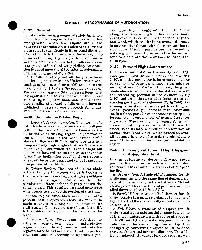
Autogyros. Early autogyros used flapping as the designed method of correcting dissymmetry of lift. Flapping causes continual aerodynamic change of the angle of attack during each re- volution of the rotor blades, which equalizes lift across the rotor disc. Figure 2-35 illustrates the self-adjusting rotor blade tip-path plane rising and descending on its flapping hinges. This ac- tion creates a relative wind component that re- duces the angle of attack on the advancing blade and increases the angle of attack on the
2-20
FM 1-51
retreating blade. As a result of this action, dis- symmetry of lift is corrected. Lift is then equalized between the advancing and retreat- ing half of the system. The aviator’s control of the tippath is through control of fuselage at- titudes by use of conventional airplane controls (elevator for noseup or nosedown; rudder for noseleft or noseright; and aileron for bank con- trol). The fully articulated rotor will follow any attitude change of the fuselage. Later models had a “direct control” rotor which was control- led by the pilot tilting the rotor head. On these models the ailerons and wings were eliminated.
c. Correction of Dissymmetry of Lift for Helicopters. Two questions that seem to best encompass the subject of cyclic feathering ver- sus flapping in helicopter flight are, “When does cyclic feathering correct dissymmetry of lift?” and “When does flapping correct dissymmetry of lift?”
(1) Cyclic feathering (cyclic respositioning) corrects dissymmetry of lift (para 2-32) whenever a constant attitude is maintained by the aviator during changing lift patterns that occur during—
(a) Acceleration. (b) Deceleration. (c) Rpm changes. (d) Collective pitch changes. (e) Transient gusts, wind shear, or tur-
bulence.
(2) Blade flapping action corrects dissym- metry of lift (c above) whenever an attitude change results from any of the conditions in (1) (a) through (e) above. When not prevented or corrected by the aviator, blade flapping action (blade flexing or hingeless rotors) will correct dissymmetry of lift in helicopters. Depending on whether airspeed is increased or decreased, this blade flapping action will cause a noseup or nosedown attitude change.
(3) When cyclic feathering is preventing and/or correcting dissymmetry of lift ((1) above), any action at or around the flapping hinge is due to nonaerodynamic causes such as—
(а) Nose-high or nose-low fuselage due to existing C.G.
(б) Design shortcomings of rigging bet- ween rotor, mast, and fuselage.
(4) When action at or around the flapping hinge is due to nonaerodynamic causes, the aviator’s concern is one of awareness for mast bumping, vibrations, C.G. management, and of shifting his item emphasis on daily preflight in- spection.
(5) Just as action around the knee joint of
CYCLIC CONTROL STICK FULL FORWARD
FULL LEFT
KTS
100
90
80
60
X 40 CYCLIC CENTER ON COCKPIT
FLOOR
20
HOVER
FULL AFT
FULL RIGHT
CYCLIC CONTROL STICK PLOT (TYPICAL) avn x74
Figure 2-3S. Cyclic center of control shift.
one’s leg may involve kicking, this action could also be used for kneeling, sitting, stepping, or stooping. Therefore action at the knee cannot arbitrarily be labeled “kicking.” Similarly, ac- tion around a “flapping hinge” should not be arbitrarily related to “dissymmetry of lift” and its correction.
2—35. Steady State Flight
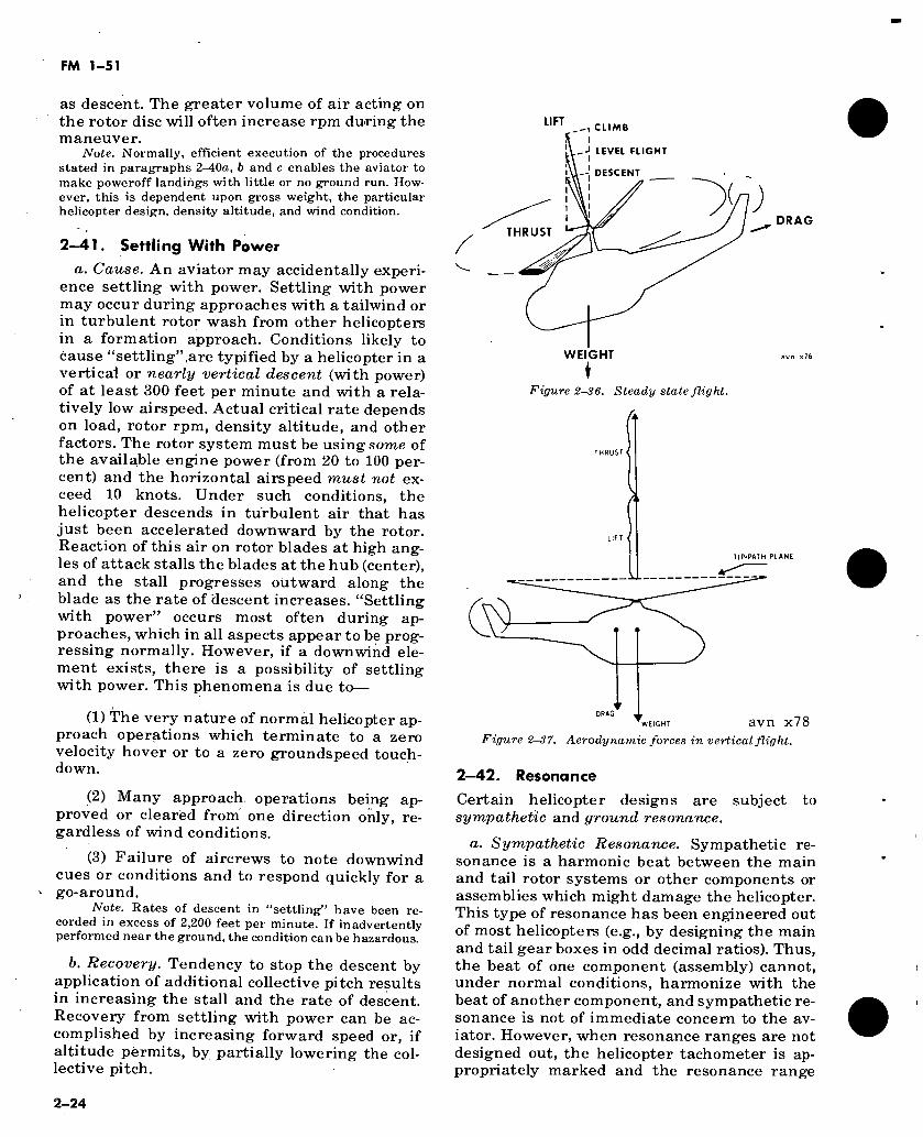
The helicopter is moved in the desired direction by the main rotor lift and its horizontal thrust component. At any steady airspeed, thrust equals drag. In forward flight, thrust is pro- jected forward (fig 2-36) from the geometric center of the rotor. Drag is projected rearward from the average center of the fuselage mass (flat plate area). This tends to produce a nose- low cruise attitude. This can be corrected by the addition of a fixed or controllable elevator to the tail boom to provide level fuselage at cruise speed. The tail boom fixed elevator is normally used on helicopters equipped with fully articu- lated rotors. On semirigid equipped helicopters, a controllable elevator is normally used to help overcome the noseup and nosedown fuselage in- ertia, thus providing good controllability. In ad- dition, it allows greater C.G. tolerance and helps to provide a level fuselage at cruise.
2—36. Vertical Flight
During vertical ascent, thrust acts vertically upward, while drag and weight act vertically downward (fig 2-37). Drag, opposing the upward motion of the helicopter, is increased by the
2-21
FM 1-51
400 KTSv^ KTS 320
(D "KD
©
480 KTS
L-TZ-©
© 80 KTS
5>^400 KTS
avn x75
Figure 2-3U- Combined system lift model. __-115 KTS __-95 KTS SS KTS 20 KTS
0 TO 10 KTS
GROUND RUNUP
ANGLE OF ATTACK RETREATING BLADE-i_B
YAW CONTROL
FUSELAGE PITCH CONTROL
95/115 KNOTS
NEAR VERTICAL DESCENT
GROUND RUNUP
ANGLE OF ATTACK ADVANCING BLADE
THRUST CONTROL
BANK CONTROL
Figure 2S5. Autogyro flapping Correcting dissymmetry of lift.
downwash of air from the main rotor. Thrust must be sufficient to overcome both weight and drag forces. Since the main rotor is responsible for both thrust and lift, the force representing the total airfoil reaction to the air may be consi- dered as two components—lift and thrust. Lift is the force component required to support the
weight of the helicopter. Thrust is the force component required to overcome the drag in vertical ascent.
Note. Many records have been made in vertical flight “time to climb” maneuvers. A recent world record estab- lished for helicopter straight-up vertical climb was 29,529 feet altitude in 6 minutes and 15.2 seconds.
2-22
FM 1-51
Section II. AERODYNAMICS OF AUTOROTATION
2-37. General a. Autorotation is a means of safely landing a
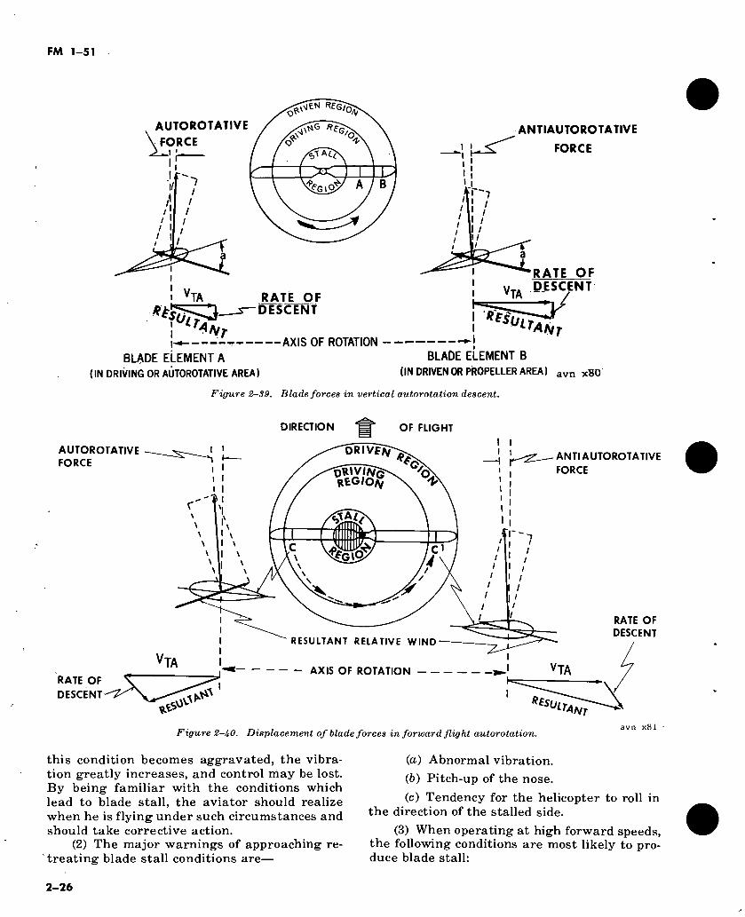
helicopter after engine failure or certain other emergencies. When the engine stops, the helicopter transmission is designed to allow the main rotor to turn freely in its original direction of rotation. It is the term used for rotary wing power-off gliding. A gliding airfoil performs as well in a small 48-foot circle (fig 2-34) as it does straight ahead in fixed wing gliding. Autorota- tion is based upon the old reliable aerodynamics of the gliding airfoil (fig 2-38).
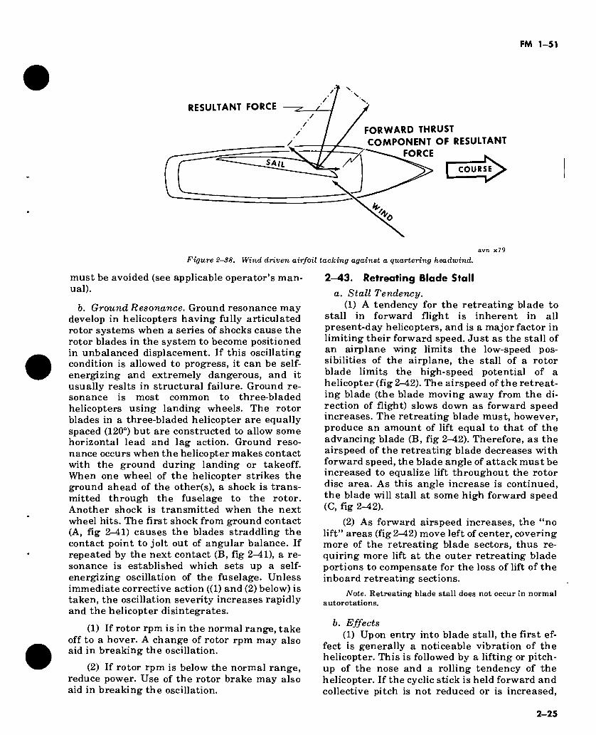
b. Gliding airfoils power all the gas turbines and jet engines now in use. Under certain wind conditions at sea, gliding airfoil principles (see driving element A, fig 2-39) provide sail power. For example, figure 2-38 shows a sailboat tack- ing against a quartering headwind. Gliding air- foils (A, fig 2-39) have made safe aircraft land- ings possible after engine failures and have es- tablished impressive world records for endur- ance and distance sailplane records.
2—38. Autorotation Driving Region
a. Rotor blade driving region. The portion of a rotor blade between approximately 25 to 70 per- cent of the radius (fig 2-39) is known as the autorotative or driving region. It performs in the same manner as the wind driven airfoil shown in figure 2-38. This region operates at a comparatively high angle of attack (blade ele- ment A, fig 2-39), which results in a slight but important forward inclination of aerodynamic force. This inclination supplies thrust slightly ahead of the rotating axis and tends to speed up this portion of the blade.
b. Driven Region. The area of a rotor blade outboard of the 70 percent radius is known as the propeller or driven region. Analysis of blade element B in figure 2-39 shows that the aerodynamic force inclines slightly behind the rotating axis. This results in a small drag force which tends to slow the tip portion of the blade.
c. Stall Region. Since blade area inboard of 25 percent radius operates above its maximum angle of attack (stall angle), it is known as the stall region. This region contributes little lift but considerable drag, which tends to slow the blade.
d. Rotor Rpm. Rotor rpm stabilizes or achieves equilibrium when autorotative region’s force (thrust) and antiautorotative region’s force (drag) are equal. If rotor rpm has been increased by entering an updraft, a gen-
eral lessening in angle of attack will follow along the entire blade. This causes more aerodynamic force vectors to incline slightly backward, which results in an overall decrease in autorotative thrust, with the rotor tending to slow down. If rotor rpm has been decreased by entering a downdraft, autorotative forces will tend to accelerate the rotor back to its equilib- rium rpm.
2—39. Forward Flight Autorotations
In forward autorotation, the aerodynamic reg- ions (para 2-38) displace across the disc (fig 2-40), and the aerodynamic force perpendicular to the axis of rotation changes sign (plus or minus) at each 180° of rotation; i.e., the given blade element supplies an autorotative force in the retreating position (blade element C, fig 2-40) and an antiautorotative force in the ad- vancing position (blade element C1, fig 2-40). As- suming a constant collective pitch setting, an overall greater angle of attack of the rotor disc (as in a flare, para 2-40c) increases rotor rpm; a lessening in overall angle of attack decreases rotor rpm. The most common cause for an in- crease in rotor rpm is the bank and turn. In effect, it is usually a circular deceleration or partial flare (para 2—405) which causes an over- all increase in angle of attack, thereby placing more blade area in the autorotative (driving) region.
2—40. Conversion of Forward Flight Airspeed in Autorotation to Lift
During autorotative descent, forward speed permits the aviator to incline the rotor disc rearward. This results in a trade-off of airspeed for lift.
a. Deceleration. A trade-off of airspeed for lift while maintaining the same line of descent. De- celeration is normally initiated at 75 to 125 feet above ground level (AGL) and progressively ap- plied down to 10 to 15 feet AGL.
b. Partial Flare. A trade-off of airspeed for lift which results in a moderate change to the line of flight. Partial flare is normally initiated at 50 to 75 feet AGL.
c. Full Flare. A trade-off of airspeed for lift which results in a substantial change to the line of flight. In autorotation with cruise airspeed at 30 to 60 feet AGL or greater (depending on the helicopter), the descending line of flight is changed by converting airspeed to lift, so as to parallel the ground for some distance. The addi- tional induced lift reduces forward speed as well
2-23
FM 1-51
as descent. The greater volume of air acting on the rotor disc will often increase rpm during the maneuver.
Note. Normally, efficient execution of the procedures stated in paragraphs 2^40a, b and c enables the aviator to make poweroff landings with little or no ground run. How- ever, this is dependent upon gross weight, the particular helicopter design, density altitude, and wind condition.
2—41. Settling With Power
a. Cause. An aviator may accidentally experi- ence settling with power. Settling with power may occur during approaches with a tailwind or in turbulent rotor wash from other helicopters in a formation approach. Conditions likely to cause “settling”.are typified by a helicopter in a vertical or nearly vertical descent (with power) of at least 300 feet per minute and with a rela- tively low airspeed. Actual critical rate depends on load, rotor rpm, density altitude, and other factors. The rotor system must be using some of the available engine power (from 20 to 100 per- cent) and the horizontal airspeed must not ex- ceed 10 knots. Under such conditions, the helicopter descends in turbulent air that has just been accelerated downward by the rotor. Reaction of this air on rotor blades at high ang- les of attack stalls the blades at the hub (center), and the stall progresses outward along the blade as the rate of descent increases. “Settling with power” occurs most often during ap- proaches, which in all aspects appear to be prog- ressing normally. However, if a downwind ele- ment exists, there is a possibility of settling with power. This phenomena is due to—
(1) The very nature of normal helicopter ap- proach operations which terminate to a zero velocity hover or to a zero groundspeed touch- down.
(2) Many approach, operations being ap- proved or cleared from one direction only, re- gardless of wind conditions.
(3) Failure of aircrews to note downwind cues or conditions and to respond quickly for a
1 go-around. Note. Rates of descent in “settling” have been re-
corded in excess of 2,200 feet per minute. If inadvertently performed near the ground, the condition can be hazardous.
b. Recovery. Tendency to stop the descent by application of additional collective pitch results in increasing the stall and the rate of descent. Recovery from settling with power can be ac- complished by increasing forward speed or, if altitude permits, by partially lowering the col- lective pitch.
LIFT CLIMB
t LEVEL FLIGHT
DESCENT
THRUST DRAG
WEIGHT
Figure 2-36. Steady state flight.
TIP-PATH PLANE
DRAG WEIGHT avn x78
Figure 2-37. Aerodynamic forces in vertical flight.
2-42. Resonance
Certain helicopter designs are subject to sympathetic and ground resonance.
a. Sympathetic Resonance. Sympathetic re- sonance is a harmonic beat between the main and tail rotor systems or other components or assemblies which might damage the helicopter. This type of resonance has been engineered out of most helicopters (e.g., by designing the main and tail gear boxes in odd decimal ratios). Thus, the beat of one component (assembly) cannot, under normal conditions, harmonize with the beat of another component, and sympathetic re- sonance is not of immediate concern to the av- iator. However, when resonance ranges are not designed out, the helicopter tachometer is ap- propriately marked and the resonance range
2-24
FM 1-51
RESULTANT FORCE
SAIL
-J
h»
FORWARD THRUST
COMPONENT OF RESULTANT FORCE
I COURSE^-
avn x79
Figure 2-38, Wind driven airfoil tacking against a quartering headwind.
must be avoided (see applicable operator’s man- ual).
b. Ground Resonance. Ground resonance may develop in helicopters having fully articulated rotor systems when a series of shocks cause the rotor blades in the system to become positioned in unbalanced displacement. If this oscillating condition is allowed to progress, it can be self- energizing and extremely dangerous, and it usually resits in structural failure. Ground re- sonance is most common to three-bladed helicopters using landing wheels. The rotor blades in a three-bladed helicopter are equally spaced (120°) but are constructed to allow some horizontal lead and lag action. Ground reso- nance occurs when the helicopter makes contact with the ground during landing or takeoff. When one wheel of the helicopter strikes the ground ahead of the other(s), a shock is trans- mitted through the fuselage to the rotor. Another shock is transmitted when the next wheel hits. The first shock from ground contact (A, fig 2-41) causes the blades straddling the contact point to jolt out of angular balance. If repeated by the next contact (B, fig 2-41), a re- sonance is established which sets up a self- energizing oscillation of the fuselage. Unless immediate corrective action ((1) and (2) below) is taken, the oscillation severity increases rapidly and the helicopter disintegrates.
(1) If rotor rpm is in the normal range, take off to a hover. A change of rotor rpm may also aid in breaking the oscillation.
(2) If rotor rpm is below the normal range, reduce power. Use of the rotor brake may also aid in breaking the oscillation.
2—43. Retreating Blade Stall
a. Stall Tendency. (1) A tendency for the retreating blade to
stall in forward flight is inherent in all present-day helicopters, and is a major factor in limiting their forward speed. Just as the stall of an airplane wing limits the low-speed pos- sibilities of the airplane, the stall of a rotor blade limits the high-speed potential of a helicopter (fig 2—42). The airspeed of the retreat- ing blade (the blade moving away from the di- rection of flight) slows down as forward speed increases. The retreating blade must, however, produce an amount of lift equal to that of the advancing blade (B, fig 2—42). Therefore, as the airspeed of the retreating blade decreases with forward speed, the blade angle of attack must be increased to equalize lift throughout the rotor disc area. As this angle increase is continued, the blade will stall at some high forward speed (C, fig 2-42).
(2) As forward airspeed increases, the “no lift” areas (fig 2—42) move left of center, covering more of the retreating blade sectors, thus re- quiring more lift at the outer retreating blade portions to compensate for the loss of lift of the inboard retreating sections.
Note. Retreating blade stall does not occur in normal autorotations.
b. Effects (1) Upon entry into blade stall, the first ef-
fect is generally a noticeable vibration of the helicopter. This is followed by a lifting or pitch- up of the nose and a rolling tendency of the helicopter. If the cyclic stick is held forward and collective pitch is not reduced or is increased,
2-25
FM 1-51
AUTOROTATIVE FORCE
/ / / I /
7 /
! VTA
RfG/ SIEN 0/^
t*G “fG
Z\AQ
?3C fG
RATÉ OF DESCENT
■AXIS OF ROTATION
BLADE ELEMENT A
(IN DRIVING OR AUTOROTATIVE AREA)
ANTIAUTOROTATIVE
FORCE
RATE OF DESCENT
►!
BLADE ELEMENT B
(IN DRIVEN OR PROPELLER AREA) avn XB0
Figure 2-89. Blade forces in vertical autorotation descent.
DIRECTION
AUTOROTATIVE FORCE
OF FLIGHT
RATE OF
DESCENT
ANTI AUTOROTATIVE FORCE
DRIVF/v ♦S
OK'V/tfG RtG/Ofy
O ■V
$ÍG\d
ff
RESULTANT RELATIVE WIND
- AXIS OF ROTATION - -
^v’ ESULTANT
Figure 2-1,0. Displacement of blade forces in forward flight autorotation.
RATE OF DESCENT
avn XÖ1
this condition becomes aggravated, the vibra- tion greatly increases, and control may be lost. By being familiar with the conditions which lead to blade stall, the aviator should realize when he is flying under such circumstances and should take corrective action.
(2) The major warnings of approaching re- treating blade stall conditions are—
(a) Abnormal vibration.
(b) Pitch-up of the nose.
(c) Tendency for the helicopter to roll in the direction of the stalled side.
(3) When operating at high forward speeds, the following conditions are most likely to pro- duce blade stall:
2-26
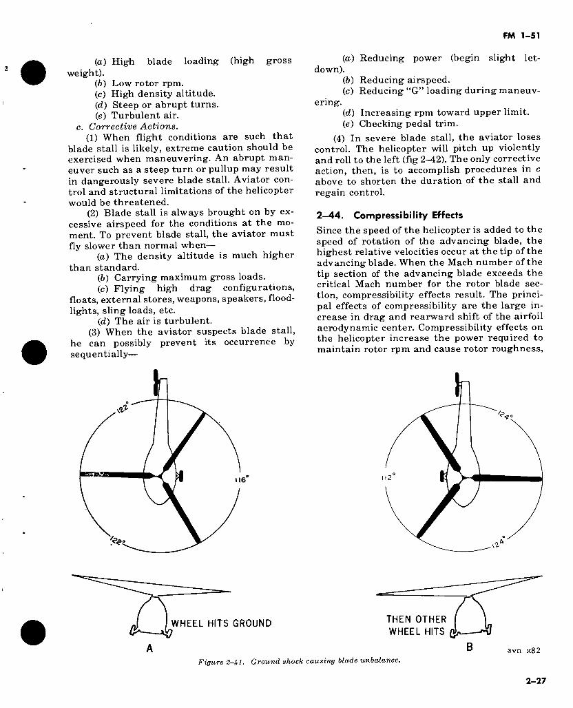
FM 1-51
(a) High blade loading (high gross weight).
(b) Low rotor rpm. (c) High density altitude. (d) Steep or abrupt turns. (e) Turbulent air.
c. Corrective Actions. (1) When flight conditions are such that
blade stall is likely, extreme caution should be exercised when maneuvering. An abrupt man- euver such as a steep turn or pullup may result in dangerously severe blade stall. Aviator con- trol and structural limitations of the helicopter would be threatened.
(2) Blade stall is always brought on by ex- cessive airspeed for the conditions at the mo- ment. To prevent blade stall, the aviator must fly slower than normal when—
(a) The density altitude is much higher than standard.
(b) Carrying maximum gross loads. (c) Flying high drag configurations,
floats, external stores, weapons, speakers, flood- lights, sling loads, etc.
(d) The air is turbulent. (3) When the aviator suspects blade stall,
he can possibly prevent its occurrence by sequentially—
(а) Reducing power (begin slight let- down).
(б) Reducing airspeed. (c) Reducing “G” loading during maneuv-
ering. (d) Increasing rpm toward upper limit. (e) Checking pedal trim.
(4) In severe blade stall, the aviator loses control. The helicopter will pitch up violently and roll to the left (fig 2-42). The only corrective action, then, is to accomplish procedures in c above to shorten the duration of the stall and regain control.
2—44. Compressibility Effects
Since the speed of the helicopter is added to the speed of rotation of the advancing blade, the highest relative velocities occur at the tip of the advancing blade. When the Mach number of the tip section of the advancing blade exceeds the critical Mach number for the rotor blade sec- tion, compressibility effects result. The princi- pal effects of compressibility are the large in- crease in drag and rearward shift of the airfoil aerodynamic center. Compressibility effects on the helicopter increase the power required to maintain rotor rpm and cause rotor roughness,
WHEEL HITS GROUND THEN OTHER
WHEEL HITS
avn x82
Figure 2-Jtl. Ground shock causing blade unbalance.
2-27
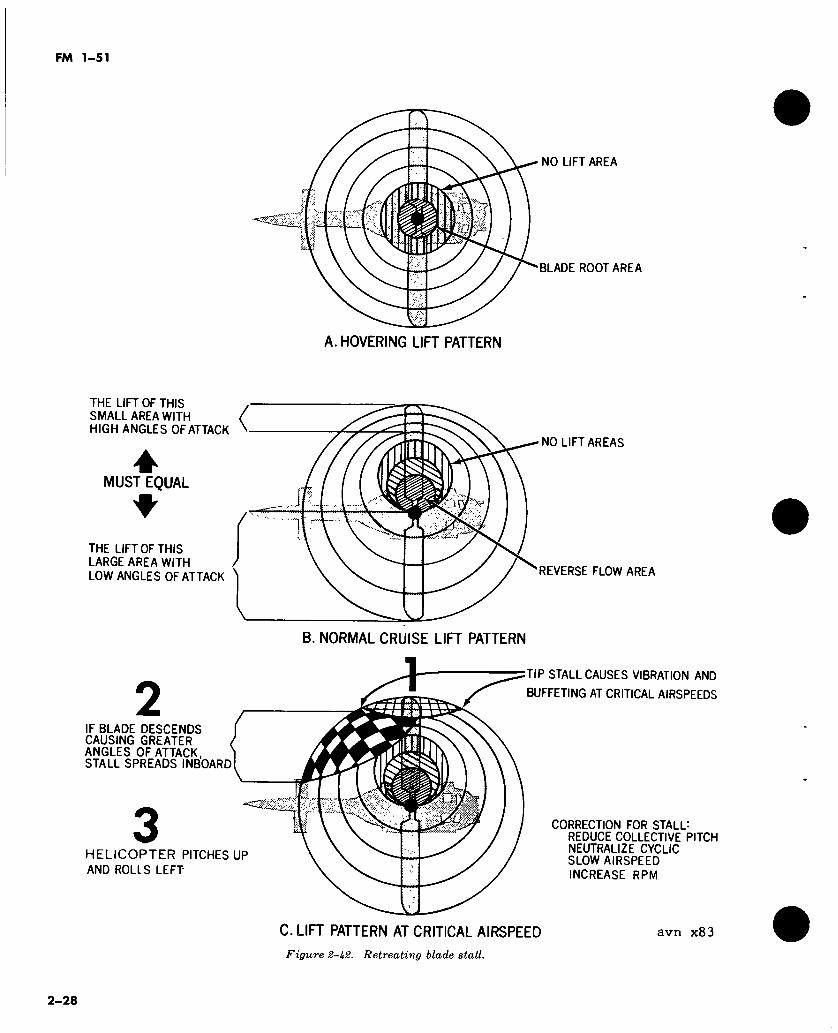
FM 1-51
A. HOVERING LIFT PATTERN
NO LIFT AREA
BLADE ROOT AREA
THE LIFT OF THIS SMALL AREA WITH HIGH ANGLES OF ATTACK
* MUST EQUAL
THE. LIFT OF THIS LARGE AREA WITH
LOW ANGLES OF ATTACK
< NO LIFT AREAS
REVERSE FLOW AREA
B. NORMAL CRUISE LIFT PATTERN
2 IF BLADE DESCENDS CAUSING GREATER ANGLES OF ATTACK, STALL SPREADS INBOARD
3 HELICOPTER PITCHES UP
AND ROLLS LEFT
□ l U
kJ
TIP STALL CAUSES VIBRATION AND
BUFFETING AT CRITICAL AIRSPEEDS
C. LIFT PATTERN AT CRITICAL AIRSPEED
CORRECTION FOR STALL: REDUCE COLLECTIVE PITCH NEUTRALIZE CYCLIC SLOW AIRSPEED
INCREASE RPM
avn x83
Figure 2-U2. Retreating blade stall.
2-28
FM 1-51
vibration, cyclic shake, and an undesirable structural twisting of the blade.
a. Adverse Operating Conditions. Compressi- bility effects become more severe at higher lift coefficients (higher blade angles of attack) and higher Mach numbers. The following operating conditions represent the most adverse compres- sibility conditions:
(1) High airspeed. (2) High rotor rpm. (3) High gross weight. (4) High density altitude. (5) Low temperature. The speed of sound is
proportional to the square root of the absolute temperature. Therefore, sonic velocity will be
more easily obtained at low temperatures when the sonic speed is lower.
(6) Turbulent air. Sharp gusts momentarily increase the blade angle of attack and thus lower the critical Mach number to the point where compressibility effects may be encoun- tered on the blade.
b. Corrective Actions. Compressibility effects will vanish by decreasing the blade pitch. The similarities in the critical conditions for retreat- ing blade stall and compressibility should be noticed but one basic difference must be ap- preciated. Compressibility occurs at high rpm while retreating blade stall occurs at low rpm. With the exception of rpm control, recovery technique is identical for both.
Section III. EFFECT OF ATMOSPHERE ON FLIGHT
2-45. Atmospheric Pressure
Atmospheric pressure is the result of the weight of all individual molecules in any given column of the atmosphere. If, for example, a cubic foot of dry, pure air in a column of the atmosphere weighs approximately 0.07651 pounds, any rela- tive cubic foot of air resting on this one will weigh less because there is less air above it.
2-46. Atmospheric Density and Density Al- titude
a. Atmospheric Density. Any volume of air is less dense than the air on which it rests. Assum- ing a constant temperature, the density of a volume of air will vary directly with the pres- sure. If the pressure is doubled, the density is doubled; if the pressure is halved, the density is halved. The new density compares to the same fractional part of standard density as the new pressure to a fractional part of the standard pressure.
b. Density Altitude. Density altitude refers to a theoretical density which exists under the standard conditions of a given altitude. The effi- ciency of an airfoil, either wings or rotor blades, is impaired at high altitudes by the lack of air density. All aircraft, regardless of design, have an eventual ceiling limit where the air is too “thin” to provide enough lift to sustain flight. The effect of air density on helicopter perfor- mance is vital due to the relative slow forward airspeed and steep vertical descent and takeoff.
2-47. Factors Affecting Air Density
a. Temperature. Even when pressure remains constant, great changes in air density will be caused by temperature changes. The same
amount of air that occupies 1 cubic inch at a low temperature will expand and occupy 2, 3, or 4 cubic inches as the temperature goes higher and higher. It is easier for an airplane or helicopter to take off in cold weather when the air is dense than in hot weather when the air is thin, be- cause the wings or blades must displace a cer- tain amount of air in taking off. In taking off from a high altitude field on a hot day, an airp- lane will require a longer than ordinary run and a helicopter may require a ground run rather than a normal takeoff. The air at the higher altitude would be thin not only because of the decrease in density caused by higher tempera- ture, but also because of the lower pressure found at the higher elevation.
b. Moisture. When temperature and pressure are constant, changes in the moisture content of the air will change air density. Air always con- tains some moisture in the form of water vapor, but the amount varies from almost none to 100 percent humidity. The density of the air de- creases as the moisture content increases. Therefore, aircraft taking off from a high al- titude field on a hot, humid day will require additional ground roll to get off the ground, due to the further reduced density resulting from high humidity.
2—48. Effects of air Density on Helicopter Per- formance
Air density is directly affected by temperature, pressure, and humidity. Any change in temper- ature, pressure, or humidity will cause air de- nsity to change and this change affects lift. To sustain level flight when these changes occur,
2-29
FM 1-51
the angle of attack of the rotary blade must be increased to develop more lift. This condition requires more power which may not be availa- ble. When the engine operating limits are ex-
ceeded, the load must be reduced. To determine the effects of density altitude upon gross weight limitations, refer to the appropriate aircraft operator’s manual.
2-30
FM 1-51
CHAPTER 3
GENERAL HELICOPTER FLIGHT TECHNIQUES
Section I. INTRODUCTION
3-1. General
a. All aviator training requirements outlined in this chapter follow the principles of attitude flying (para 3-2). In accordance with this con- cept, all aviator performance is based upon knowledge, planning, projection, and prediction—with control action, feel, touch and coordination being items of cross-check. Subject matter for aviation training according to these principles is listed below. It is necessary that emphasis be given to the subject areas in this order—
(1) Knowledge of aerodynamics, physics, and mechanics of flight.
(2) Specific knowledge of the systems, com- ponents, controls, and structures of the helicop- ter being used.
(3) Knowledge of the methods and rules of attitude flying which are similar to the rules of attitude instrument flying in TM 1-215.
(4) Specific knowledge of the breakdown of attitudes and cross-checks for each maneuver; and development in dividing attention and cross-checking outward from a specific center of attention for each segment of a maneuver.
(5) Development of smooth and coordinated physical application of controls: the ability to hold specific attitudes and power settings or to change attitudes and power (in accordance with (3) and (4) above).
b. The physical application of the controls (a(5) above) is considered to be less important in the initial stages of training than the other four subject areas. Professional aviators become so proficient in these subject areas that they ap- pear to fly the helicopter with little movement of the controls. Their skill is the result of thorough application of the principles in a(l) through (4) above during the learning and prac- tice phases of training. This application be- comes habitual, then automatic.
c. In flying, basic techniques are generally applicable to all aircraft. The attitude flying concept, introduced and enlarged during prim- ary flight training, promotes deep learning and habit patterns. It provides for easy transition
into larger, more complex aircraft, and permits smooth progression through instrument flight training and rapid growth toward full opera- tional stature. The mechanics and techniques of flight, correctly learned in early training, pro- duce aviators who are highly standardized and free of the so-called “common” errors. The new student should be cautioned against “shortsigh- ted” objectives such as early solo or rapid trans- ition into every aircraft in the inventory. In- stead the student should study and exercise the basic concepts of attitude contact flying, and later attitude instrument flying. He must pos- sess a working knowledge of how the compo- nents and vital systems of modern aircraft func- tion. With this acquired knowledge, he can then fashion and tailor flight performance to the needs of future flight assignments.
3—2. Attitude flying
a. Since all maneuver segments and exercises are tied to specific flight attitudes, an adequate attitude grid frame or reference must be found or provided. A technique is to provide an index mark on the helicopter windshield.
b. The attitude index mark must be discussed prior to the first takeoff. It can be made with a grease pencil by placing three t4-inch circles vertically along the center line of vision, which is a vertical plane extending through the pilot’s eyes, the cyclic stick, and the gap between the pedals. It is not necessary that these marks be exactly placed for the exact flight attitudes for acceleration, climb, cruise, slow cruise, and de- celeration can be quickly found in relation to these marks.
c. The student should be familiar with the normal flight attitudes, airspeeds, and power settings for the specific helicopters. This in- struction is usually presented by the instructor thorugh the use of pictures, slides, or hand sketches prior to the first flight.
d. Prior information should include— (1) The attitudes normal for the specific
helicopter for hovering acceleration, climb, slow cruise, cruise, and deceleration.
3-1
FM 1-51
(2) The effect of various “center of gravity” conditions upon these normal flight attitudes (i.e. fuel burnoff and various loads may affect the C.G.).
(3) The average power settings normally used for climb, slow cruise, cruise, and descent.
(4) Correct pedal use (where to look and what to look for) during hovering, climbout, and approach.
(5) Correct pedal settings normally used for good trim in coordinated flight for climb cruise, descent, and autorotation.
(6) Correct pedal use for initiating a coordi- nated turn (usually none in single rotor helicop- ters).
(7) Correct pedal use during steady state turn (usually slight inside pedal).
e. All maneuvers described in this chapter are presented as flight training exercises. Each flight exercise is designed to evoke thought pro- cesses, to expand knowledge, and to develop the ability to divide attention and cross-check in a manner that promotes correct physical re- sponse on the controls.
Section II. GROUND OPERATIONS AND HOVERING
3—3. Preflight Inspection
Once the helicopter aviator has been assigned the mission and filed his flight plan, he is ready to begin his preflight inspection. Before he leaves for the flight line, he checks all available sources for possible information on the mission to be flown. Then he checks any available sum- maries as to organizational or aviator reports on the assigned helicopter’s suitability for the intended mission.
a. Actual preflight inspections are nothing more than a detailed comparison of the assigned helicopter to the aviator’s mental image or idea of a standard helicopter (in type and model), and to the different types of helicopters he has in- spected in the past. Aviator proficiency in pre- flight inspection is gained by a slow accumula- tion of daily comparison experience. The more experience the aviator has, the more precise is his image of the standard helicopter. Check of the helicopter forms and records provides addi- tional information for this comparison. A pub- lished preflight checklist (-CL) for each helicop- ter provides the sequence of inspection to be followed.
b. Key points for an aviator’s preflight in- spection proficiency include—
(1) A knowledge of helicopter component design and maintenance practices.
(2) A firm and detailed mental image of the “zero time” (new) appearance of the type helicopter to be flown.
(3) Adherence to the published preflight checklist which provides a sequence of inspec- tion to be followed.
(4) Development of genuine interest and curiosity in helicopter design and maintenance problems.
c. As the student becomes more familiar with the helicopter, a good preflight inspection using the -CL requires approximately 15 minutes on
small helicopters and up to 30 minutes on larger configurations. Preflight inspection time, when totaled on a monthly basis, constitutes a heavy time allotment. For example, 20 preflight in- spections per month at 30 minutes each equal 600 minutes or 10 hours. This time should in- volve a continuing study of helicopter design and maintenance problems. The professional aviator should keep notes on his findings and make careful and objective written reports. He should follow through with aviator reports and participation in maintenance and design discus- sions or conferences. The appropriate mainte- nance manual should be immediately available for use in clarifying suspected discrepancies.
d. School training in preflight inspection pro- vides only the methods of inspections; compari- son experience is accumulated by the aviator on the flight line.
e. In addition to the detailed comparison dis- cussed in a above, the aviator must—
(1) Check special equipment and supplies required for the mission.
(2) Check the loading of the helicopter, with special emphasis on proper weight, balance, and security.
(3) Perform the progressive sequence of checks and operations in accordance with the published cockpit and starting procedures.
(4) Perform pretakeoff check, tune radios, and obtain necessary clearances.
(5) Check operation of controls and center- of-gravity hang of the fuselage at “gear light” or “skid light” power setting prior to liftoff. (“Gear light” or “skid light” power setting is that power setting at which some of the weight of the helicopter is being supported by the rotor system.)
Note. If these checks verify that the helicopter favor- ably compares with the aviator’s image of the ideal helicop- ter, the preflight inspection is completed and the aviator is free to take off to a hover.
3-2
FM 1-51
3-4. Taxiing a. General. Helicopters equipped with wheels
and brakes have excellent taxi control charac- teristics. Those equipped with skids can be tax- ied for a few feet, but generally this type helicopter is hovered from place to place. When taxiing, the aviator must maintain adequate clearance of main rotor(s) in relation to obstruc- tions and other aircraft. He must—
(1) Insure that clearance is sufficient for the area sweep of the tail rotor during a pivotal turn.
(2) Properly use cyclic and collective pitch, for control of speed to not more than approxi- mately the speed of a brisk walk.
(3) Recognize conditions which produce ground resonance, and know the recovery pro- cedures for ground resonance.
(4) Be familiar with the standard marking for taxiways and parking areas.
(5) Be familiar with the light and hand signals used by tower and ground control per- sonnel.
b. Procedure for Taxiing. To taxi a wheel- and brake-equipped helicopter—
(1) Set rotor rpm in normal operating range.
(2) Tilt rotor tip-path plane slightly for- ward.
(3) Increase collective pitch (power) to ob- tain a moving speed of not more than that of a brisk walk.
(4) Use antitorque pedals for directional control. If helicopter has a tail wheel, it should be unlocked for turning and locked for long straight-ahead taxiing.
Note. Brakes should not be used for directonal control. However, it is general practice to apply “inside” brake for spot parking and pivotal turn control.
c. Procedure for Slowing or Stopping. For slowing or stopping the helicopter while taxiing—
(1) Level the rotor and lower pitch. (2) As the helicopter slows, touch both
brakes to stop at the desired spot. (3) For an alternate method to slow or stop,
tilt the rotor slightly rearward. The addition of collective pitch and power should then cause the helicopter to slow and finally stop.
Note. For brake failure and emergency stop, perform a takeoff to hover.
3-5. Takeoff to Hover and Landing From Hover
a. General. In all helicopters, the takeoff to
and landing from a hover is primarily an appli- cation of physics and aerodynamics. Therefore, development of aviator skill is dependent on his knowledge of the physics and aerodynamics in- volved. The smooth and apparently continuous transition from a parking position up to a stabilized hover is not a single operation. This transition contains many separate elements or key points, each of which is more of an applied thinking process than a physical skill.
b. Takeoff-to-Hover Exercise. The complete maneuver must contain all points in this exer- cise. The finished maneuver will be a smooth blend of all items listed below.
(1) Visually clear the area. Check for objects, conditions, or people that could be affected or disturbed by a hovering helicopter.
(2) Determine wind direction and velocity. Mentally review and predict the possible effect of this wind upon the helicopter at lift-off.
(3) Tune radios, make advisory calls, adjust volume. For training, all radios should be on and tuned to local facilities.
(4) Make final pretakeoff check. This check includes pressures, temperatures, electrical systems, final area check, and operating rpm.
Note. From this point until the final establishment of a stabilized hover, compare the performance, control action, center of gravity, and sound of this helicopter to the stan- dard response of your ideal helicopter of this type. If the rsponse or performance differs greatly at any point, reduce power.
(5) Increase collective pitch slowly to obtain a gear light condition or until the rotor is sup- porting some of the helicopter weight.
Note. For reciprocating engines, center attention on rpm instrument, and cross-check to manifold pressure and outward to a fixed point near the horizon. For this exercise, increase manifold pressure Vz inch at a time with collective pitch if rpm is on the mark, or with throttle if rpm is low. Center attention on rpm, with cross-check to manifold pres- sure. Decide whether the next inch of manifold pressure should be made with pitch or throttle to keep rpm on the exact mark.
(6) Be alert for the first sign of gear light condition which usually is a need for antitorque pedal repositioning. As main rotor lift increases and weight upon the landing gear becomes less, torque may turn the fuselage.
(7) Shift center of attention to a fixed point near the horizon. Hold the helicopter heading on the fixed reference point with pedal repositioning so that an imaginary line would extend from the fixed point between your feet to your seat. (See A, fig. 3-1.)
(8) Be alert for the second sign of gear light condition, which is often a need for reposition- ing of the cyclic control. Make a positive reposi- tioning of the cyclic in the direction opposite to
3-3
FM 1-51
and preventing any horizontal movement of the helicopter.
(9) Continue the increase of power to find the center of gravity (C.G.) attitude or the center of gravity hang of the fuselage, which is the fore and aft and lateral attitude of the fuselage just prior to breaking ground contact. (After breaking ground contact, this attitude is referred to as the hovering attitude.)
Note. There will be a tendency for certain portions of the landing gear to leave the ground first, due to the loca- tion of the center of gravity for each load condition. There- fore, if power is increased with heading maintained by re- positioning of pedals and all horizontal motion prevented by repositioning of the cyclic, a point will be reached where the rotor is almost supporting the full weight of the helicopter, but where some portion of the landing gear still is in contact with the ground. If excessive cyclic control displacement is required and fore or aft or lateral C.G. attitude appears excessive, reduce power and investigate.
(10) Identify the C.G. attitude (C.G. hang): check some windshield or canopy part against the horizon. If the attitude appears normal, if the controls are responding normally, and if the helicopter feels and sounds normal you are cleared to liftoff to a hover.
(11) Continue the power application and the helicopter will rise vertically to a full stabilized hover, holding its position and heading steadily without requiring noticeable change of attitude.
(12) The exercise is complete. Hover briefly prior to moving out.
c. Landing from Hover Exercise. Landing from a hover is accomplished by reversing the exer- cise given in b above.
(1) Hover briefly and position the helicopter over the intended landing spot.
(2) Select reference point near the horizon. (3) Use pedal control to hold a line from the
reference point between your feet to your seat. (4) Use cyclic to prevent any horizontal mo-
tion. If the helicopter moves horizontally in re- lation to your reference point, ease back to the original position.
(5) Attempt to reduce power a slight incre- ment at a time, with pitch, so as to develop a slow, constant downward descent.
(6) As the downward descent slows, reduce power another increment.
(7) At initial ground contact, continue the procedures in (3) through (6) above until all weight of the helicopter is on the landing gear.
(8) During early training or in transition to other helicopters, it is best to use the distant reference point as the center of attention. Cross-check downward for positioning over parking panel.
(9) More advanced aviators may center their
attention on a reference point closer to the helicopter.
Caution: To prevent ground resonance occur- ring after the landing gear touches the ground, some helicopters must land with a continuous re- duction of power.
3-6. Hovering
The stationary hover and the moving hover ap- pear to be highly skilled, coordinated physical accomplishments when executed by an experi- enced aviator, but as is true with all other maneuvers, these maneuvers can be divided into simple key point and cross-check exercises.
3—7. Stationary Hover
a. General. The stationary hover actually be- gins at that moment of takeoff to a hover when the rotor is supporting most of the weight of the helicopter. Power application will then deter- mine the height of the hover. The key points, thought processes, and cross-checks involved in hovering can be mastered by use of the exercise given in b below.
b. Stationary Hover Exercise. (1) At the moment of “lift-off,” take special
note of the exact forward horizon picture out- lined through the visual frame of hardware parts of the cockpit. Use windshield frames, the top of the radio box, instrument panel, anten- nas, or a mark (grease pencil) on the windshield glass to determine an exact hovering attitude in reference to a point on the distant horizon. It is important to use the distant horizon, for this reference will be used later to program the mov- ing hover, the normal takeoff, and the climbout.
(2) In peripheral vision, find the lateral hang of the fuselage at “lift-off,” using door frames or side window frames. The lateral hang of the fuselage can also be determined on the forward horizon picture. (The aviator will re- ceive an indication of a change in the attitude of the helicopter prior to actual movement of the helicopter. Corrections then must be applied immediately to maintain the level attitude and position of the helicopter.)
(3) Accomplish all forward or rearward hori- zontal control by slight adjustments to the noseup, nosedown attitude as measured against some distant point on or near the horizon. Use an airframe part or grease pencil mark on the distant horizon for exact attitude control.
(4) Control sideward motion by slightly rais- ing or lowering the lateral attitude (as seen in peripheral vision).
Note. Pedal turns to new headings often require establishing new attitudes and control centers when surface
3-4
FM 1-51
winds are not calm. The main rotor tilt must remain into the wind and the weathervane effect on the fuselage must be counteracted.
3-8. Characteristics of Stationary Hover a. The stationary hovering exercise is prop-
erly accomplished when—
(1) The hover is maintained by slight noseup, nosedown, and lateral attitude changes made on and around a specific and recognizable base attitude.
(2) The only cyclic control movement at any moment is that motion necessary to slightly change or hold the specific hovering attitudes (in normal wind conditions). Avoid all other movements of the cyclic control.
(3) The changes of attitude are made at a rate and amount so as not to be noticeable to a casual observer/passenger.
(4) Heading control is accomplished by prompt pedal repositioning, which holds and keeps an aviator’s feet and the pedals straddl- ing an imaginary line straight ahead to a dis- tant reference point (building, tree, bush, etc.).
(5) Hovering height is held to the specified height published in the operator’s manual by use of collective pitch.
b. The stationary hovering exercise is not properly accomplished when—
(1) The helicopter attitude is constantly changing, or there is no recognizable and obvi- ous base attitude around which the aviator is working.
(2) The noseup, nosedown, and lateral changes of attitude are made at a rate and in amounts which are noticeable to a casual observer/passenger.
(3) Due to overcontrolling, the hover is ac- complished by rapid and constant cyclic jiggl- ing, or thrashing of the cyclic without a corres- ponding change of airframe attitudes.
(4) The fuselage does not hold a constant heading on a distant reference point.
(5) The hovering height is rising and lower- ing.
Section III. h
3-11. General The normal takeoff performed from the ground or from a stationary hover has fixed, program- med elements with few variables. Once the av- iator knows where to look and what to think, what to program and what to cross-check, this maneuver will be mastered. The normal takeoff exercise given below presents the exact
(6) The horizontal positioning is unsteady and changing.
3-9. Moving Hover Exercises The moving hover is generally less difficult than the stationary hover and can be accomplished through use of the following exercises:
a. Using the base attitudes required for the stationary hover, lower the nose approximately Io or 2°.
b. Hold this attitude steady until the forward hovering rate has reached that of a brisk walk.
c. Return the attitude to the original statio- nary hovering attitude for a coasting hover. Raise the attitude slightly to reduce speed, or lower the attitude slightly to increase speed. Then, when desired speed has been attained, return to the stationary hovering attitude for a steady coasting rate.
d. Use lateral attitude control for positioning over the desired line of hover.
e. Use pedals to hold the fuselage heading parallel to the desired line of hover.
/. To stop, raise the nose Io or 2° above the stationary hovering attitude, then return to the stationary hovering attitude as all forward mo- tion is dissipated.
3-10. Precautions When Hovering Always “clear” the nose and tail in the direction of the intended turn. Maintain proper hovering height so as not to strike objects on the ground and beware of tailwind conditions. When hover- ing, watch for and avoid—
a. Possible rotorwash damage to parked airp- lanes.
b. Helicopters which have rotors turning after shutdown (blade strikes).
c. Dusty areas or loose snow (blinding swirls). d. Tents or loose debris (rotor ingestion and
damage). e. Any area v/here there is a person or object
that could be adversely affected by a hovering rotor downwash (danger area is the downwind quadrant).
(MAL TAKEOFF
thought/action/cross-check sequence required to perform this maneuver in most helicopters. See the applicable operator’s manual for direc- tions to convert this exercise to the final form required for the specific helicopter.
3—12. Pretakeoff Considerations Before taking off—
3-5
a. Select the takeoff outbound track to be used. Note the wind direction in relation to the intended outbound track.
b. Make a hovering turn to “clear” (check) the airspace for other traffic (unless cleared by tower or ground crew).
c. Sighting (projecting between the pedals (fig 3-1)), select two or three “line-up” objects (panel, bushes, trees) beyond the takeoff point, over which the outbound track is to be flown.
d. Make final pretakeoff cross-check of in- struments for systems, pressures, and tempera- tures. Check Go-No-Go takeoff data placard.
e. Hold fuselage heading on the farthest re- ference point (fig 3-1).
3—13. Normal Takeoff Exercise Note. The amount of attitude rotation in this exercise is
expressed in 1-inch increments. Because most helicopters have poor “heads up” attitude reference frames, the inch reference is used here for clarity. “Degree” increments can- not be used in general application because the distance from the pilot’s eye to the windshield varies in different helicop- ters and the windshield distance from the airframe rota- tional axis also varies.
a. Using airframe/windshield parts or grease pencil index marks (projected on the horizon ahead, para 3-2), observe the exact hovering at- titude. Experiment with the following sequence of four attitude index changes. When the degree or rate of attitude rotation is reduced or in- creased, airspeed/altitude relationship at 50 to 100 feet will be changed. When the entire at- titude rotation sequence is made at one time rather than in increments, helicopter will noticeably settle and more power will be re- quired to hold the hovering acceleration to “ef- fective translational lift.” Also note the effect when the entire attitude rotation sequence is made slower or more rapidly.
(1) Beginning at a stabilized hover, rotate the attitude index to approximately 1 inch lower than the stationary hovering attitude. If takeoff is from the ground, assure liftoff with an at- titude of 1 inch below hovering attitude. Hold this attitude constant to approximately 5 knots.
(2) Upon reaching approximately 5 knots, rotate attitude index to 2 inches lower than the hovering attitude. This will result in a notice- able acceleration. Hold heading and accelera- tion altitude constant. Use lateral cyclic to maintain ground track. Hold this attitude con- stant until reaching “effective translational lift” and until the climb begins.
(3) When the climb begins, rotate attitude index to approximately 3 inches lower than the hovering attitude. This is the final attitude
change which should be held constant thereaf- ter to gain a progressive increase in airspeed and altitude. Adjust power to near “hover power” for tentative climb power.
(4) At 50 feet, convert the “slip” to a “crab” by setting “climb pedal” or centered-ball coor- dinated climb. Upon reaching published climb airspeed, adjust the attitude index to a known or tentative “climb attitude.” Adjust to pub- lished “climb power” or for rate-of-climb to 500 feet per minute.
b. Throughout this exercise, the important items are—
(1) The programmed attitudes are held con- stant with repositioning of the cyclic control. The center of cyclic control shifts as airspeed changes. The nose will tend to rise at “effective translational lift” and thereafter as airspeed in- creases. This is due to dissymmetry of lift and the resulting blade flapping. Therefore, prompt and progressive cyclic control repositioning is required throughout the maneuver.
(2) The hovering height is maintained with collective pitch until effective translational lift is reached. Then the additional lift causes the helicopter to climb.
(3) Power is adjusted to “hover power” or set to the published climb value after climb be- gins, or adjusted to 500 feet per minute thereaf- ter.
(4) The heading is held parallel to the line of outbound reference points. Normally, the fuselage heading will tend to yaw to the left due to the streamlining effect on the fuselage and increasing efficiency of the tail rotor. Note that pedals must be repositioned to hold the heading as airspeed increases and as the climb progres- ses through various wind conditions.
(5) The helicopter positioning is maintained over the intended outbound track, controlled with lateral cyclic. Make reference points pass between the pedals or under the aviator’s seat. There is a strong tendency for the right seat aviator to crab right and drift right. The left seat aviator will crab left and drift left.
(6) Fuselage alinement parallel to intended track with pedal control and helicopter position- ing over the line of outbound track with lateral cyclic control. This is referred to as a slip, and is used from a hover up to 50 feet. In the event of engine failure during takeoff, there would be little chance to aline the fuselage with the touchdown direction; therefore, the heading must be alined with direction in a slip at all times below 50 feet. At 50 feet, reposition pedals to the “climb pedal” position for centered-ball.
3-6
FM 1-51
Usually this is a neutral pedal setting for con- version of the slip to a crab (para 3-22d(l)). Thereafter, airspeed should increase rapidly toward the published climb airspeed.
c. After conversion from the slip to crab, or when the airspeed increases to within 5 knots of the published climb airspeed—
(1) Slowly adjust attitude toward the tenta- tive or known climb attitude to maintain climb airspeed. This must be a tentative attitude based upon the aviator’s knowledge of the aver- age climb attitude for this type helicopter. Thereafter correct, verify, and solve'for a firm climb attitude. (This will probably be “slow cruise” attitude also.)
(2) To control outbound track when in a crab (above 50 feet), hold climb pedals and fly a normal banked turn with cyclic to a heading that will result in the desired track (toward a geographic fix on the selected outbound track).
3-14. Summary a. The normal takeoff is completed when
there is a climb airspeed and climb attitude, climb power and normal rpm, climb pedals and level lateral trim, and tracking is over desired outbound track.
b. The exercise is properly accomplished when—
(1) Required attitudes which result in a smooth acceleration and climb are programmed and held.
Section IV.
3-15. Introduction to Airwork (for Local Con- tact Flying Maneuvers)
a. The attitude of the aircraft to the horizon and the power applied are the only two elements of control in all aircraft. Proper use of these two elements of control will produce any desired maneuver within the capability of the aircraft. Therefore, all maneuvers, studies, and exercises of all flight requirements must be based solidly upon attitude and power control references.
b. The modifiers of the two basic control ele- ments are time of application (the initial time to apply and the length of time each attitude and power setting is applied) and the rate of change (of attitudes and power settings).
c. Keeping the basic control elements and modifiers in mind, add cross-check for a running awareness of what the aircraft is doing at the moment; knowledge and projection as to what the aircraft is going to do; and purpose and intent for exactly what the aviator wants to do.
(2) Climb power is programmed or checked at effective translational lift with rpm in normal range.
(3) In cross-check, there is good heading and track control.
(4) At 50 feet, a conversion from the slip to a crab is programed.
(5) Climb airspeed is reached, and the at- titude is rotated to climb attitude.
c. Common errors include— (1) Poor hovering height control during the
initial acceleration to translational lift.
(2) No firm attitude around which the av- iator is working. Constantly changing attitude results in poor airspeed/altitude relationship.
(3) Fuselage in a crab prior to 50 feet and/or constantly changing.
(4) No positive conversion from slip to crab at 50 feet.
(5) Poor power or rate-of-climb control dur- ing climb.
(6) Left or right wind drift away from plan- ned outbound track.
(7) Left or right drift away from outbound track due to parallax. The aviator using the left seat will tend to be well left of track. The aviator using the right seat will tend to be well right of track. For corrective action, see paragraph 3-136(5) above.
AIRWORK
The result will be attitude flying. (/.Based upon these principles, airwork pre-
sented in this section will include discussion and exercises for—
(1) Attitude control and resulting airspeed. (2) Power control and resulting altitude,
climb, or descent. (3) Heading control and resulting track or
turns, and antitorque control and resulting lat- eral trim.
3—16. Attitude Control and Resulting Airs- peed
a. Airspeed is a result of attitude control. To hold any desired airspeed or make properly con- trolled changes of airspeed, the aviator must—
(1) Prior to flight, have formed a clear men- tal image of basic attitudes normally expected of the helicopter he is to fly. For example, what are the attitudes (of this type helicopter) for hover,
3-7
FM 1-51
normal acceleration, deceleration, climb, or cruise?
(2) Beginning with the first takeoff to a hover, solve for the exact basic attitudes of the helicopter being flown. How do these basic at- titudes compare with the basic attitudes of the ideal helicopter (para 3-3a) or with other helicopters of the same type?
b. During the first few minutes of flight the aviator must make the comparisons described in a above, using tentative attitudes to solve for the actual basic attitudes prior to engaging in further maneuvers or precision flying exercises.
3—17. Attitude Control Exercise
a. With center of attention on the exact attitude being held for the desired flight condi- tion, cross-check the airspeed indicator.
b. Predict how this attitude is going to affect the airspeed in the next few seconds of flight.
(1) Will it hold the airspeed now indicated? (2) Will it cause a slowing of airspeed? (3) Will it cause an increase of airspeed?
Note. Do not concentrate on the airspeed indicator. It is an amount gage, showing only the amount of airspeed at the moment. It cannot be used to predict airspeed in future seconds; therefore, use it in cross-check only. Do con- centrate your center of attention on attitude (to the exact degree on the horizon) to predict airspeed in future seconds.
c. Hold the attitude steady, change it momen- tarily, or rotate to a new attitude which, in pre- diction, will result in the airspeed desired. Cross-check the airspeed indicator frequently to assure that the attitude now being held is af- fecting the airspeed as expected.
d. The exercise is being correctly performed when the aviator—
(1) Rotates to an attitude that, in predic- tion, will accelerate or decelerate to a desired airspeed.
(2) Cross-checks the approaching airspeed indication desired.
(3) Rotates the attitude to a specific at- titude that, in prediction, will hold the desired airspeed.
(4) Holds the attitude constant. While in cross-check, he observes the total flight condi- tion (mission, maneuver, other traffic, altitude, rpm, lateral trim, and track); he cross-checks the airspeed indicator—is it low? high? or steady?
Note. The aviator makes slight attitude changes to return to the proper airspeed reading (when necessary), but returns to his last proven attitude when the airspeed is corrected. After two or three corrections in the same direc- tion, he modifies his proven attitude slightly.
e. The exercise is completed when each step is
performed smoothly, promptly, with precision, and without noticeable distraction to the total flight.
3—18. Power Control and Resulting Altitude, Climb, or Descent
Altitude is a result of power control. To properly change to or hold any desired altitude, the av- iator must—
a. Prior to flight, have a clear mental image of tentative or basic power settings normally ex- pected for the type helicopter to be flown. For example, what are the power settings (of the average machine of this type) for hover, climb, cruise, slow cruise, and descent? What differ- ences could normally be expected for various gross weights and density altitude combina- tions?
b. Upon the first takeoff to a hover and there- after, solve for the exact basic power settings required for precise altitude control for the helicopter being flown. For good altitude con- trol, this study must be completed before engag- ing in further maneuvers or precision flying ex- ercises on this flight.
3-19. Altitude Control Exercises
а. Altitude Control Exercise (Climb). (1) With center of attention on attitude for
control of a stable climb airspeed, cross-check and maintain climb power. Climb power will be published (or as required to maintain a 500 feet per minute rate of climb).
(2) Use pedals to aline the fuselage with the outbound track. At 50 feet, reposition the pedals to “climb pedals,” which usually is a neutral setting.
(3) Conduct a running cross-check on climb power, since it will be necessary to add correc- tions as altitude is gained and as atmosphere becomes less dense.
б. Altitude Control Exercise (Cruise). (1) When the climb has reached to within 50
feet of the cruise altitude, rotate the attitude to an acceleration attitude.
(2) When the airspeed reaches cruise airs- peed, rotate the attitude to a tentative or known cruise attitude.
(3) Upon reaching the desired cruise al- titude, begin a reduction of power to a tentative or known cruise power setting.
(4) Solve for the exact power setting re- quired to hold the desired altitude. Use 1 or 2 increments above and below this reading for minor altitude corrections (of 40 feet or less).
3-8
FM 1-51
Use the published climb or descent power set- ting for large altitude corrections.
Note. Do not concentrate on the altimeter; use it in cross-check only. The altimeter is only an amount gage, showing the amount of altitude at the moment. It cannot be used to predict altitude in future seconds. Do use exact power settings (to the exact mark) for predicting and con- trolling altitude trends in future seconds, assuming a stable attitude/airspeed.
c. Altitude Control Exercise (Slow Cruise). (1) Rotate the attitude to a tentative or
known slow cruise attitude. (2) Lower the power to a tentative or known
slow cruise power setting (usually 3 to 5 pounds torque below cruise setting).
Note. Coordinate antitorque pedals with the power reduction in the amount required to prevent yaw during the power change. (Check exact pedal setting required for slow cruise by referring to lateral trim or a centered ball.)
(3) Solve for the exact power setting re- quired to hold the desired altitude. Use 2 to 5 pounds torque above or below this reading for minor altitude corrections.
Note. “Slow cruise” airspeed is the same airspeed as normal climb or normal descent airspeed. Slow cruise power is that power required to maintain altitude at slow cruise airspeed.
d. Altitude Control Exercise (Descent). (1) With cruise or slow cruise
attitude/airspeed, reduce power to the power setting needed to establish a 500 feet per minute descent.
(2) Coordinate pedals to prevent yaw during power change.
(3) Center attention on attitude, with cross- check to power setting and/or 500 feet per mi- nute descent.
e. Deceleration Exercise. Although this exer- cise is used primarily for coordination practice, decleration can be used to effect a rapid decel- eration, or a quick stop. The maneuver requires a high degree of coordination of all controls. The purpose of the maneuver is to maintain a con- stant altitude and heading, while slowing the helicopter to a desired, predetermined airspeed. To accomplish the maneuver—
(1) Decrease collective pitch while coor- dinating aft cyclic control, while slowing the helicopter smoothly and maintaining a constant altitude.
(2) At the same time, continuously apply an- titorque pedals as necessary to hold a constant heading. (The attitude of the helicopter becomes increasingly nose-high until the desired airs- peed is neared.)
(3) After speed has been reduced the desired amount, return the helicopter to a normal cruise by lowering the nose with cyclic to accel-
erate forward while adding collective pitch to maintain altitude.
(4) Use pedal to hold the desired heading. f. Completion of Exercises. These altitude con-
trol exercises are completed when all items are performed smoothly, promptly, and with preci- sion. The objective is accomplished when each exercise is performed without noticeable dis- traction to the total flight; i.e., mission, man- euver, systems management, other traffic, and navigation.
3-20. Rpm Control (Reciprocating Engines Only)
a. Helicopter power controls are designed to combine the following three functions into the collective pitch stick:
(1) A twist-grip throttle serves as the handle for the collective pitch stick. Gripping the throt- tle and rotating the wrist outward will add throttle; rotating the wrist inward will decrease throttle.
(2) Raising and lowering the collective pitch stick will increase or decrease the pitch or angle of incidence of the main rotor blades.
(3) A throttle correlation unit is added to the collective pitch linkage. Once this device is set by the throttle for the desired engine rpm, it will automatically add more throttle as the collec- tive pitch is raised and reduce throttle as the collective pitch is lowered. Thus, in theory, this unit will maintain constant rpm as the main rotor loads change. However, being of simple cam design, this correlation device usually works properly only in a narrow range. Increas- ing collective pitch above or below this range usually results in undersirable rpm changes, which must be corrected.
b. To learn rpm control requires study, prac- tice, and experimentation by the aviator. He must develop a visual cross-check of the rpm. He must, at times, use the sound of the engine or the whine of the transmission to recognize rpm variations. Some throttles require a slight rota- tion of the wrist outward or inward as the col- lective pitch is raised or lowered. This permits rpm to be exactly maintained throughout the full power range from maximum allowable power (pitch up) to collective pitch full down in needles-joined autorotation.
3—21. Rpm Control Exercises (Reciprocating Engines Only)
Rpm control exercises, when accomplished step by step and until their performance is automa- tic, will give the aviator an apparent effortless
3-9
FM 1-51
control of rpm. These exercises are divided into three distinct flight groups that require study and practice, as follows: а. Rpm control and correction during steady
state climb, cruise, and descent: (1) If rpm is high:
(a) Note manifold pressure reading. (ft) Rotate throttle to achieve a decrease of
V2 to 1 inch of manifold pressure. (c) Increase collective pitch V2 to 1 inch of
manifold pressure (returning to original read- ing in step (a) above).
(d) Cross-check other traffic, attitude, al- titude, and track. After approximately 3 sec- onds, cross-check rpm for completed correction. If still high, repeat the exercise.
(2) If rpm is low: (a) Note manifold pressure reading. (ft) Rotate throttle to achieve an increase
of x/2 to 1 inch of manifold pressure. (c) Reduce collective pitch V2 to 1 inch of
manifold pressure (returning to original read- ing in step (a) above).
(d) Cross-check other traffic, attitude, al- titude, and track. After approximately 3 sec- onds, cross-check rpm for completed correction. If still low, repeat the exercise.
б. Rpm control and correction during large manifold pressure changes:
(a) Reduce manifold pressure with collec- tive pitch while cross-checking rpm gage.
(ft) If rpm is slightly high, make the next inch manifold pressure reduction with throttle.
(c) Reduce manifold pressure steadily with pitch and/or throttle in 1-inch increments so as to maintain the desired rpm.
Note. Keep the manifold pressure needle moving in peripheral vision and rpm gage in constant cross-check.
(d) Upon reaching the desired manifold pressure for steady state descent, make further corrections to rpm as in a above.
(2) Rpm control while increasing collective pitch:
(a) Increase manifold pressure with col- lective pitch while cross-checking rpm gage.
(ft) If rpm is slightly low, make the next inch manifold pressure increase with throttle.
(c) Increase manifold pressure steadily with pitch and/or throttle in 1-inch increments so as to maintain the desired rpm.
Note. Keep the manifold pressure needle moving in peripheral vision and rpm gage in constant cross-check.
(d) Upon reaching the desired manifold pressure for steady state climb, make further corrections to rpm as in a above.
c. Rpm control and correction during hover- ing or approaches on predetermined line of des- cent.
(1) If rpm is high: (a) Cross-check rpm frequently. (ft) Note manifold pressure reading. (c) At a hover, reduce 1 inch of manifold
pressure with throttle and use collective pitch to maintain the desired hovering height.
(d) On approach, reduce Y2 inch (or less) of manifold pressure with throttle and use collec- tive pitch to control line of descent.
(e) Cross-check rpm. If still high, repeat exercise.
(2) If rpm is low: (.a) Cross-check rpm frequently. (ft) Note manifold pressure reading. (c) At a hover, add 1 inch of manifold
pressure with throttle and use collective pitch to maintain the desired hovering height.
(d) On approach, add V2 inch (or less) of manifold pressure with throttle and use collec- tive pitch to control line of descent.
(e) Cross-check rpm. If still low, repeat exercise.
3—22. Antitorque Pedals
a. General. The primary purpose of the an- titorque pedals is to counteract torque (para 2-15). However, the antitorque system usually is designed to have surplus thrust, far beyond that required to counteract torque. This addi- tional thrust, designed into the tail rotor sys- tem, is used to provide positive and negative thrust for taxi direction control and to coun- teract the weathervane effect of the fuselage in crosswind operations. In certain helicopter con- figurations, care must be exercised in using the thrust power of the antitorque system, since damage to the tail pylon area can result from overstress during fast-rate hovering pedal turns and during taxi conditions over rough ground. (Some tail rotor designs may demand up to 20 percent of the total engine output. This power should be used with caution.)
ft. Areas of Consideration. Antitorque pedals are the most misused of the helicopter controls. There are three separate modes of control for correct pedal use, and each of these modes must be analyzed and treated separately by the av- iator.
(1) The first group includes normal helicop- ter operations below 50 feet, during which the fuselage is alined with a distant point. This group includes taking off to and landing from a hover, the stationary hover, the moving hover,
3-10
FM 1-51
the takeoff and climb slip control, and the ap- proach slip control.
(2) The second group includes coordinated flight and all operations above 50 feet which require pedal use to align and hold the fuselage into the relative wind.
(3) The third group includes proper pedal use in turns. Coordinated turns (at altitude) re- quire the proper use of pedals to keep the fusel- age into the relative wind as the bank is in- itiated, established, and maintained.
c. Heading and Track Control for Operations Below 50 Feet.
(1) Taking off to and landing from a hover require that pedals be repositioned to hold and maintain the nose alinement with a distant re- ference point. The aviator uses an imaginary line to a distant object and applies pedal to posi- tion and maintain the line of sight from his seat through the cyclic and the gap between his ped- als (A, fig. 3-1). Aviators in either seat use the same distant reference point with no appreci- able error. Fuselage alinement to hovering or takeoff direction is shown in B of figure 3-1.
(2) During the moving hover and the initial climb to 50 feet, pedals control heading as in figure 3-1, and cyclic control is used for direc- tion and lateral positioning over the intended track as in figure 3-2. Using peripheral vision (and cross-check), the helicopter should be positioned with lateral cyclic so the imaginary line is seen running through position 1 (fig 3-2) during taxi or run-on landings, and position 2 for hovering and climb through 20 feet. The line should be seen between pedals as shown at posi- tion 3 for all altitudes over 20 feet, with all track reference points lined up and passing between pedals in passage over each point.
Note. Beginning students may use the method shown in A, figure 3-1 to determine track alinement for all man- euvers.
(3) In crosswind operations, the combined use of pedals and cyclic as in (2) above results in a sideslip, commonly referred to as a slip. The aviator does not consciously think slip, for he is automatically in a true slip if he holds the fusel- age alined on a distant object with pedals (fig 3-1) and maintains positioning over the line with cyclic (fig 3-2).
d. Heading and Track Control for Operations Above 50 Feet.
(1) For coordinated flight above 50 feet, the pedals assume a purely antitorque role and are promptly repositioned to a climb pedal setting upon reaching 50 feet. This pedal action con- verts the'slip to a crab, that alines the fuselage
with the relative wind, rather than with a dis- tant object.
(а) The helicopter is now in coordinated flight, during which the cyclic controls fuselage heading, the rotor disc is level laterally, and the ball is centered.
(б) The track is now controlled by a coor- dinated cyclic bank and turn to a heading that will result in the desired track. Tracking toward and over selected ground reference points will cause these reference points to pass directly under the aviator’s seat cushion.
(2) Pedals are hereafter coordinated with power changes and should not be used for head- ing control. The use of pedals to prevent the momentary yaw of the nose due to gusts should be avoided in early training. Do not move the pedals unless there is a power change.
(3) Power changes require sufficient coor- dinated pedal to prevent the fuselage from yaw- ing left or right. When the power change is com- pleted, crosscheck the new pedal setting and lateral trim of the fuselage.
(4) Generally, the average single rotor helicopter will have pedal settings which are normal for various power/speed combinations. Coordinate these settings with power changes and hold in cross-check (for all operations and coordinated flight above 50 feet).
(5) Rigging of pedal control linkage will vary in helicopters of the same type. Therefore, in steady climb, cruise, descent, or autorotation, with pedals set, cross-check—
(a) Turn-and-slip indicator for a centered ball. Pedal into the low ball and note the exact pedal setting required when ball is centered.
(b) Door frames or windshield frames for lateral level trim. Pedal into the low side and / note the exact pedal setting required. 1
(c) Main rotor tip-path plane. It should be the same distance above the horizon on each side. For level rotor, pedal into the low side.
Note. If the pedal position required is far removed from the normal settings, write up “pedals out of rig.”
(6) In semirigid main rotor configurations, note the lateral hang of the fuselage at a hover (into the wind). If the fuselage is not level, due to a lateral C.G. displacement, then the one-side low condition must be accepted as level; there- after, in flight (airwork over 50 feet) adjust ped- als for a lateral trim of one-side low as existed at a hover. Even though the fuselage is one side low, the rotor is laterally level to the horizon and the helicopter is in trimmed flight. Proceed as in (5) (c) above.
e. Pedal Use in Turns. Use of pedal to enter
3-11
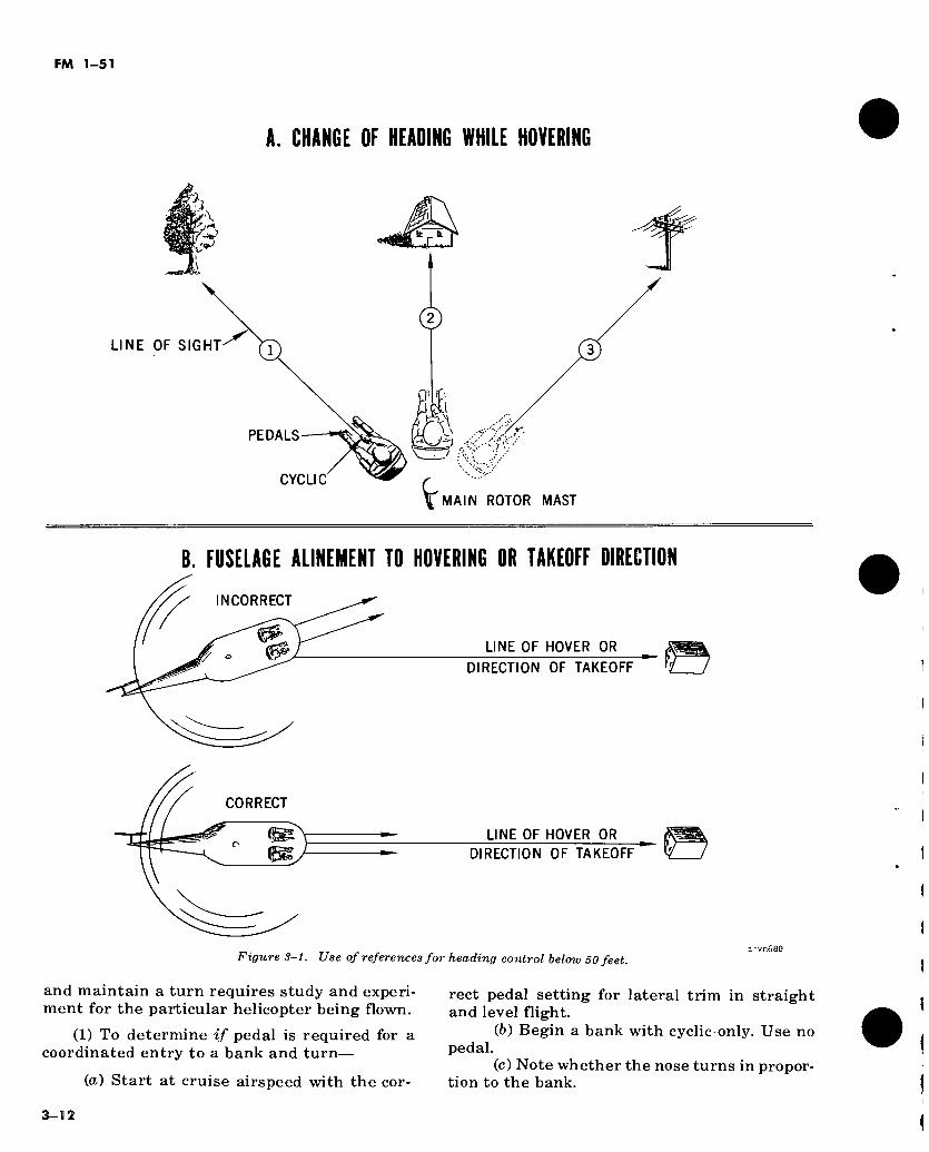
FM 1-51
A. CHANGE OF HEADING WHILE HOVERING
t _ k
©
s\ ^=3
LINE OF SIGHT
PEDALS
CYCLIC
MAIN ROTOR MAST
B. FUSELAGE ALINEMENT TO HOVERING OR TAKEOFF DIRECTION
INCORRECT
y °
CORRECT
LINE OF HOVER OR
DIRECTION OF TAKEOFF
LINE OF HOVER OR
DIRECTION OF TAKEOFF
Figure 8-1. Use of references for heading control below 50 feet. vp.sae
and maintain a turn requires study and experi-
ment for the particular helicopter being flown.
(1) To determine if pedal is required for a
coordinated entry to a bank and turn—
(a) Start at cruise airspeed with the cor-
rect pedal setting for lateral trim in straight
and level flight.
(6) Begin a bank with cyclic only. Use no
pedal. (c) Note whether the nose turns in propor-
tion to the bank.
3-12
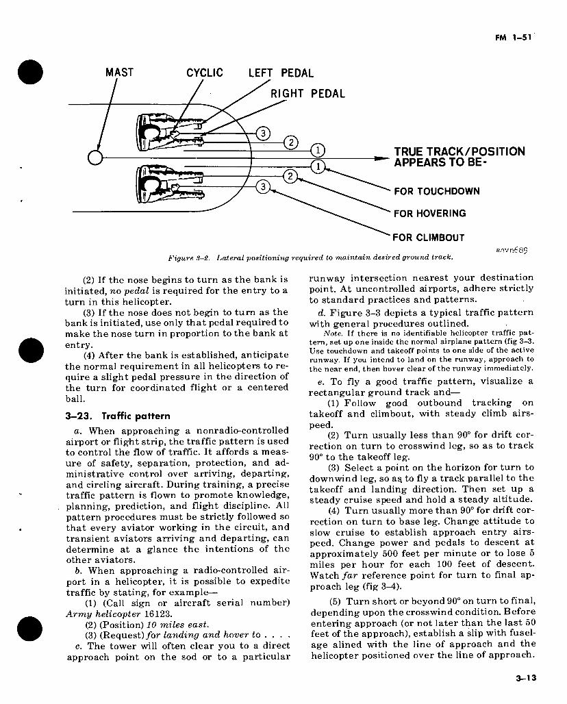
FM 1-51
MAST CYCLIC LEFT PEDAL
RIGHT PEDAL
© © © TRUE TRACK/POSITION APPEARS TO BE-
FOR TOUCHDOWN
FOR HOVERING
FOR CLIMBOUT
Figure 3-2. Lateral positioning required to maintain desired ground track. aavn689
(2) If the nose begins to turn as the bank is initiated, no pedal is required for the entry to a turn in this helicopter.
(3) If the nose does not begin to turn as the bank is initiated, use only that pedal required to make the nose turn in proportion to the bank at entry.
(4) After the bank is established, anticipate the normal requirement in all helicopters to re- quire a slight pedal pressure in the direction of the turn for coordinated flight or a centered ball.
3-23. Traffic pattern a. When approaching a nonradio-controlled
airport or flight strip, the traffic pattern is used to control the flow of traffic. It affords a meas- ure of safety, separation, protection, and ad- ministrative control over arriving, departing, and circling aircraft. During training, a precise traffic pattern is flown to promote knowledge, planning, prediction, and flight discipline. All pattern procedures must be strictly followed so that every aviator working in the circuit, and transient aviators arriving and departing, can determine at a glance the intentions of the other aviators.
b. When approaching a radio-controlled air- port in a helicopter, it is possible to expedite traffic by stating, for example—
(1) (Call sign or aircraft serial number) Army helicopter 16123.
(2) (Position) 10 miles east. (3) (Request)/or landing and hover to ... .
c. The tower will often clear you to a direct approach point on the sod or to a particular
runway intersection nearest your destination point. At uncontrolled airports, adhere strictly to standard practices and patterns.
d. Figure 3-3 depicts a typical traffic pattern with general procedures outlined.
Note. If there is no identifiable helicopter traffic pat- tern, set up one inside the normal airplane pattern (fig 3-3. Use touchdown and takeoff points to one side of the active runway. If you intend to land on the runway, approach to the near end, then hover clear of the runway immediately.
e. To fly a good traffic pattern, visualize a rectangular ground track and—
(1) Follow good outbound tracking on takeoff and climbout, with steady climb airs- peed.
(2) Turn usually less than 90° for drift cor- rection on turn to crosswind leg, so as to track 90° to the takeoff leg.
(3) Select a point on the horizon for turn to downwind leg, so as. to fly a track parallel to the takeoff and landing direction. Then set up a steady cruise speed and hold a steady altitude.
(4) Turn usually more than 90° for drift cor- rection on turn to base leg. Change attitude to slow cruise to establish approach entry airs- peed. Change power and pedals to descent at approximately 500 feet per minute or to lose 5 miles per hour for each 100 feet of descent. Watch far reference point for turn to final ap- proach leg (fig 3^1).
(5) Turn short or beyond 90° on turn to final, depending upon the crosswind condition. Before entering approach (or not later than the last 50 feet of the approach), establish a slip with fusel- age alined with the line of approach and the helicopter positioned over the line of approach.
3-13
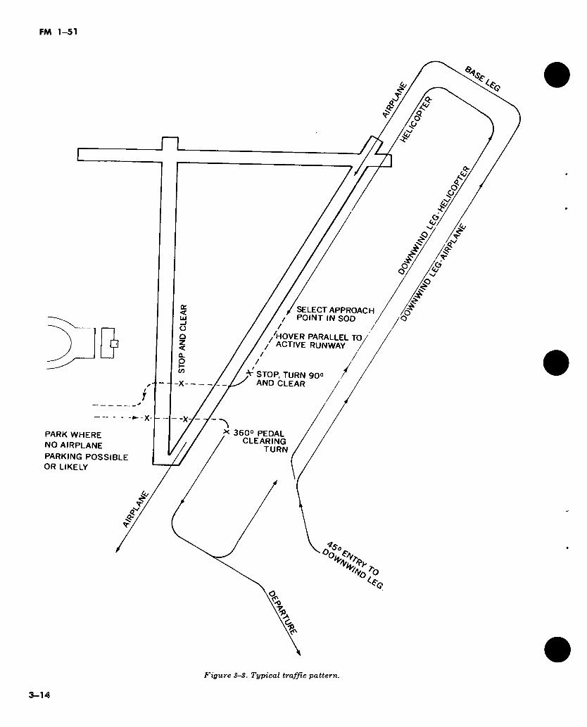
FM 1-51
Ta kf
s <c
<ï-
/ / / SELECT APPROACH / / POINT IN SOD /
/ y /
f /'HOVER PARALLEL TO / / ACTIVE RUNWAY /
' / / / ¿r STOP, TURN 90°
AND CLEAR
►X
*■ 360° PEDAL / CLEARING
TURN
k,
ft-
fa
O.
PARK WHERE NO AIRPLANE
PARKING POSSIBLE OR LIKELY
Figure S-3. Typical traffic pattern.
3-14
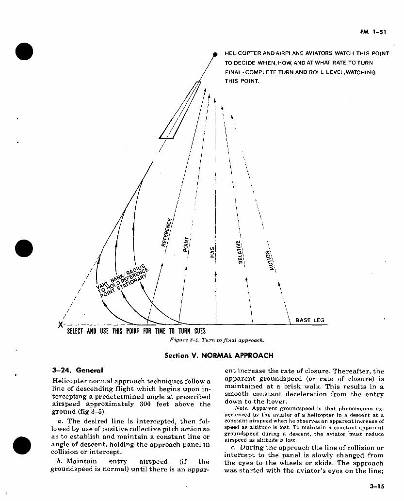
FM 1-51
HELICOPTER AND AIRPLANE AVIATORS WATCH THIS POINT
TO DECIDE WHEN, HOW, AND AT WHAT RATE TO TURN
FINAL-COMPLETE TURN AND ROLL LEVEL,WATCHING
THIS POINT.
/
X -
l ,0.^0^
4 a.
BASE LEG
SELECT AND USE THIS POINT FOR TIME TO TURN CUES Figure 3-h. Turn to final approach.
Section V. NORMAL APPROACH
3—24. General Helicopter normal approach techniques follow a line of descending flight which begins upon in- tercepting a predetermined angle at prescribed airspeed approximately 300 feet above the ground (fig 3-5).
a. The desired line is intercepted, then fol- lowed by use of positive collective pitch action so as to establish and maintain a constant line or angle of descent, holding the approach panel in collision or intercept.
b. Maintain entry airspeed (if the groundspeed is normal) until there is an appar-
ent increase the rate of closure. Thereafter, the apparent groundspeed (or rate of closure) is maintained at a brisk walk. This results in á smooth constant deceleration from the entry down to the hover.
Note. Apparent groundspeed is that phenomenon ex- perienced by the aviator of a helicopter in a descent at a constant airspeed when he observes an apparent increase of speed as altitude is lost. To maintain a constant apparent groundspeed during a descent, the aviator must reduce airspeed as altitude is lost.
c. During the approach the line of collision or intercept to the panel is slowly changed from the eyes to the wheels or skids. The approach was started with the aviator’s eyes on the line;
3-15
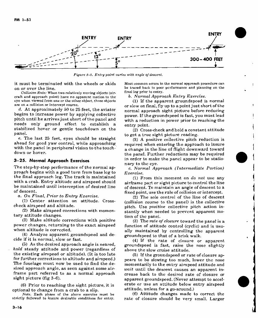
FM 1-51
I
ENTRY ENTRY
ENTRY
t 'F
300-400 FEET
Figure 3-5. Entry point varies with angle of descent.
it must be terminated with the wheels or skids on or over the line.
Collision Rule: When two relatively moving objects (air- craft and approach point) have no apparent motion to the eye when viewed from one or the other object, those objects are on a collision or intercept course.
d. At approximately 50 to 25 feet, the aviator begins to increase power by applying collective pitch until he arrives just short of the panel and needs only ground effect to establish a stabilized hover or gentle touchdown on the panel.
e. The last 25 feet, eyes should be straight ahead for good yaw control, while approaching with the panel in peripheral vision to the touch- down or hover.
3—25. Normal Approach Exercises
The step-by-step performance of the normal ap- proach begins wdth a good turn from base leg to the final approach leg. The track is maintained with a crab. Entry altitude and airspeed should be maintained until interception of desired line of descent.
a. On Final, Prior to Entry Exercise. (1) Center attention on attitude. Cross-
check airspeed and altitude. (2) Make airspeed corrections with momen-
tary attitude changes. (3) Make altitude corrections with positive
power changes, returning to the exact airspeed when altitude is corrected.
(4) Analyze apparent groundspeed and de- cide if it is normal, slow or fast.
(5) As the desired approach angle is neared, hold steady attitude and power (regardless of the existing airspeed or altitude). (It is too late for further corrections to altitude and airspeed.) The fuselage must now be used to find the de- sired approach angle, as seen against some air- frame part referred to as a normal approach sight picture (fig 3-6).
(6) Prior to reaching the sight picture, it is optional to change from a crab to a slip.
Note. Each phase of the above exercise must be strictly followed to insure desirable conditions for entry.
Most common errors in the normal approach procedure can be traced back to poor performance and planning on the final leg prior to entry.
b. Normal Approach Entry Exercise. (1) If the apparent groundspeed is normal
or slow on final, fly up to a point just short of the normal approach sight picture before reducing power. If the groundspeed is fast, you must lead with a reduction in power prior to reaching the entry point.
(2) Cross-check and hold a constant attitude to get a true sight picture reading.
(3) A positive collective pitch reduction is required when entering the approach to insure a change in the line of flight downward toward the panel. Further reductions may be required in order to make the panel appear to be statio- nary to the eye.
c. Normal Approach (Intermediate Portion) Exercise.
(1) From this moment on do not use any airframe part or sight picture to control the line of descent. To maintain an angle of descent to a fixed point, use the rule of collision or intercept.
(2) The sole control of the line of descent (collision course to the panel) is the collective pitch. Use positive collective pitch action in- stantly when needed to prevent apparent mo- tion of the panel.
(3) The rate of closure toward the panel is a function of attitude control (cyclic) and is usu- ally maintained by controlling the apparent groundspeed to that of a brisk walk.
(4) If the rate of closure or apparent groundspeed is fast, raise the nose slightly above the slow cruise attitude.
(5) If the groundspeed or rate of closure ap- pears to be slowing too much, lower the nose momentarily to the entry airspeed attitude and wait until the descent causes an apparent in- crease back to the desired rate of closure or apparent groundspeed. (Never attempt to accel- erate or use an attitude below entry airspeed attitude, unless for a go-around.)
(6) Attitude changes made to correct the rate of closure should be very small. Larger
3-16
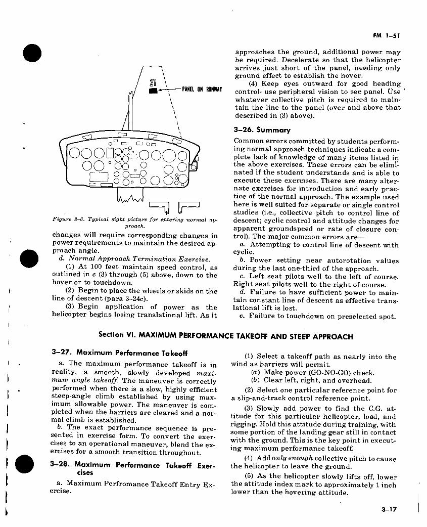
FM 1-51
O LJ O □
PANEL ON RUNWAY
ooonggboooô] qo°o8 o 1,0 8?^ o od ■.a <=i
H f Figure 3-6. Typical sight picture for entering normal ap-
proach.
changes will require corresponding changes in power requirements to maintain the desired ap- proach angle.
d. Normal Approach Termination Exercise. (1) At 100 feet maintain speed control, as
outlined in c (3) through (5) above, down to the hover or to touchdown.
(2) Begin to place the wheels or skids on the line of descent (para 3-24c).
(3) Begin application of power as the helicopter begins losing translational lift. As it
approaches the ground, additional power may be required. Decelerate so that the helicopter arrives just short of the panel, needing only ground effect to establish the hover.
(4) Keep eyes outward for good heading control- use peripheral vision to see panel. Use whatever collective pitch is required to main- tain the line to the panel (over and above that described in (3) above).
3-26. Summary
Common errors committed by students perform- ing normal approach techniques indicate a com- plete lack of knowledge of many items listed in the above exercises. These errors can be elimi- nated if the student understands and is able to execute these exercises. There are many alter- nate exercises for introduction and early prac- tice of the normal approach. The example used here is well suited for separate or single control studies (i.e., collective pitch to control line of descent; cyclic control and attitude changes for apparent groundspeed or rate of closure con- trol). The major common errors are—
a. Attempting to control line of descent with cyclic.
b. Power setting near autorotation values during the last one-third of the approach.
c. Left seat pilots well to the left of course. Right seat pilots well to the right of course.
d. Failure to have sufficient power to main- tain constant line of descent as effective trans- lational lift is lost.
e. Failure to touchdown on preselected spot.
Section VI. MAXIMUM PERFORMANCE TAKEOFF AND STEEP APPROACH
3-27. Maximum Performance Takeoff
a. The maximum performance takeoff is in reality, a smooth, slowly developed maxi- mum angle takeoff. The maneuver is correctly performed when there is a slow, highly efficient steep-angle climb established by using max- imum allowable power. The maneuver is com- pleted when the barriers are cleared and a nor- mal climb is established.
b. The exact performance sequence is pre- sented in exercise form. To convert the exer- cises to an operational maneuver, blend the ex- ercises for a smooth transition throughout.
3-28. Maximum Performance Takeoff Exer- cises
a. Maximum Perfromance Takeoff Entry Ex- ercise.
(1) Select a takeoff path as nearly into the wind as barriers will permit.
(а) Make power (GO-NO-GO) check. (б) Clear left, right, and overhead.
(2) Select one particular reference point for a slip-and-track control reference point.
(3) Slowly add power to find the C.G. at- titude for this particular helicopter, load, and rigging. Hold this attitude during training, with some portion of the landing gear still in contact with the ground. This is the key point in execut- ing maximum performance takeoff.
(4) Add only enough collective pitch to cause the helicopter to leave the ground.
(5) As the helicopter slowly lifts off, lower the attitude index mark to approximately 1 inch lower than the hovering attitude.
3-17
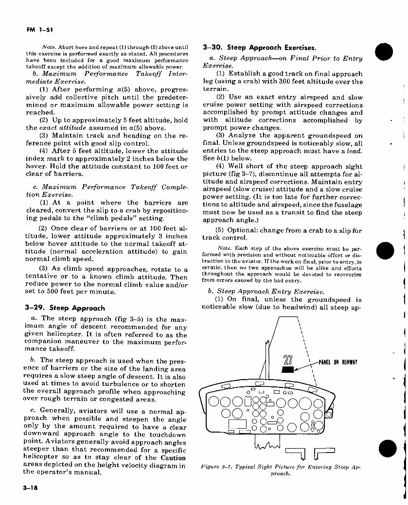
FM 1-51
Note. Abort here and repeat (1) through (5) above until this exercise is performed exactly as stated. All procedures have been included for a good maximum performance takeoff except the addition of maximum allowable power.
b. Maximum Performance Takeoff Inter- mediate Exercise.
(1) After performing a(5) above, progres- sively add collective pitch until the predeter- mined or maximum allowable power setting is reached.
(2) Up to approximately 5 feet altitude, hold the exact attitude assumed in a(5) above.
(3) Maintain track and heading on the re- ference point with good slip control.
(4) After 5 feet altitude, lower the attitude index mark to approximately 2 inches below the hover. Hold the attitude constant to 100 feet or clear of barriers.
c. Maximum Performance Takeoff Comple- tion Exercise.
(1) At a point where the barriers are cleared, convert the slip to a crab by reposition- ing pedals to the “climb pedals” setting.
(2) Once clear of barriers or at 100 feet al- titude, lower attitude approximately 3 inches below hover attitude to the normal takeoff at- titude (normal acceleration attitude) to gain normal climb speed.
(3) As climb speed approaches, rotate to a tentative or to a known climb attitude. Then reduce power to the normal climb value and/or set to 500 feet per minute.
3-29. Steep Approach a. The steep approach (fig 3-5) is the max-
imum angle of descent recommended for any given helicopter. It is often referred to as the companion maneuver to the maximum perfor- mance takeoff.
b. The steep approach is used when the pres- ence of barriers or the size of the landing area requires a slow steep angle of descent. It is also used at times to avoid turbulence or to shorten the overall approach profile when approaching over rough terrain or congested areas.
c. Generally, aviators will use a normal ap- proach when possible and steepen the angle only by the amount required to have a clear downward approach angle to the touchdown point. Aviators generally avoid approach angles steeper than that recommended for a specific helicopter so as to stay clear of the Caution areas depicted on the height velocity diagram in the operator’s manual.
3-30. Steep Approach Exercises. a. Steep Approach—on Final Prior to Entry
Exercise. (1) Establish a good track on final approach
leg (using a crab) with 300 feet altitude over the terrain.
(2) Use an exact entry airspeed and slow cruise power setting with airspeed corrections accomplished by prompt attitude changes and with altitude corrections accomplished by prompt power changes.
(3) Analyze the apparent groundspeed on final. Unless groundspeed is noticeably slow, all entries to the steep approach must have a lead. See 5(1) below.
(4) Well short of the steep approach sight picture (fig 3-7), discontinue all attempts for al- titude and airspeed corrections. Maintain entry airspeed (slow cruise) attitude and a slow cruise power setting. (It is too late for further correc- tions to altitude and airspeed, since the fuselage must now be used as a transit to find the steep approach angle.)
(5) Optional: change from a crab to a slip for track control.
Note. Each step of the above exercise must be per- formed with precision and without noticeable effort or dis- traction to the aviator. If the work on final, prior to entry, is erratic, then no two approaches will be alike and efforts throughout the approach would be devoted to recoveries from errors caused by the bad entry.
b. Steep Approach Entry Exercise. (1) On final, unless the groundspeed is
noticeable slow (due to headwind) all steep ap-
C=> O Q □ O □
o
PANEL ON RUNWAY
oooasgûoooô] °0”o8 o .o o° o O Oo\¿ -<=□ i i
AA/WA
Figure 3-7. Typical Sight Picture for Entering Steep Ap- proach.
3-18
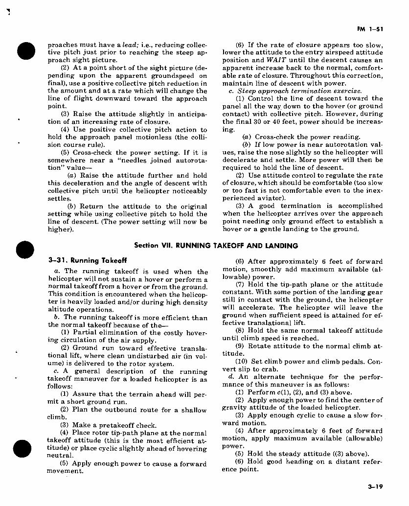
FM 1-51
proaches must have a lead; i.e., reducing collec- tive pitch just prior to reaching the steep ap- proach sight picture.
(2) At a point short of the sight picture (de- pending upon the apparent groundspeed on final), use a positive collective pitch reduction in the amount and at a rate which will change the line of flight downward toward the approach point.
(3) Raise the attitude slightly in anticipa- tion of an increasing rate of closure.
(4) Use positive collective pitch action to hold the approach panel motionless (the colli- sion course rule).
(5) Cross-check the power setting. If it is somewhere near a “needles joined autorota- tion” value—
(а) Raise the attitude further and hold this deceleration and the angle of descent with collective pitch until the helicopter noticeably settles.
(б) Return the attitude to the original setting while using collective pitch to hold the line of descent. (The power setting will now be higher).
Section VII. RUNNING
3-31. Running Takeoff
a. The running takeoff is used when the helicopter will not sustain a hover or perform a normal takeoff from a hover or from the ground. This condition is encountered when the helicop- ter is heavily loaded and/or during high density altitude operations.
b. The running takeoff is more efficient than the normal takeoff because of the—
(1) Partial elimination of the costly hover- ing circulation of the air supply.
(2) Ground run toward effective transla- tional lift, where clean undisturbed air (in vol- ume) is delivered to the rotor system.
c. A general description of the running takeoff maneuver for a loaded helicopter is as follows:
(1) Assure that the terrain ahead will per- mit a short ground run.
(2) Plan the outbound route for a shallow climb.
(3) Make a pretakeoff check. (4) Place rotor tip-path plane at the normal
takeoff attitude (this is the most efficient at- titude) or place cyclic slightly ahead of hovering neutral.
(5) Apply enough power to cause a forward movement.
(6) If the rate of closure appears too slow, lower the attitude to the entry airspeed attitude position and WAIT until the descent causes an apparent increase back to the normal, comfort- able rate of closure. Throughout this correction, maintain line of descent with power.
c. Steep approach termination exercise. (1) Control the line of descent toward the
panel all the way down to the hover (or ground contact) with collective pitch. However, during the final 30 or 40 feet, power should be increas- ing.
(а) Cross-check the power reading. (б) If low power is near autorotation val-
ues, raise the nose slightly so the helicopter will decelerate and settle. More power will then be required to hold the line of descent.
(2) Use attitude control to regulate the rate of closure, which should be comfortable (too slow or too fast is not comfortable even to the inex- perienced aviator).
(3) A good termination is accomplished when the helicopter arrives over the approach point needing only ground effect to establish a hover or a gentle landing to the ground.
kKEOFF AND LANDING
(6) After approximately 6 feet of forward motion, smoothly add maximum available (al- lowable) power.
(7) Hold the tip-path plane or the attitude constant. With some portion of the landing gear still in contact with the ground, the helicopter will accelerate. The helicopter will leave the ground when sufficient speed is attained for ef- fective translational lift.
(8) Hold the same normal takeoff attitude until climb speed is reached.
(9) Rotate attitude to the normal climb at- titude.
(10) Set climb power and climb pedals. Con- vert slip to crab.
d. An alternate technique for the perfor- mance of this maneuver is as follows:
(1) Perform c(l), (2), and (3) above. (2) Apply enough power to find the center of
gravity attitude of the loaded helicopter. (3) Apply enough cyclic to cause a slow for-
ward motion. (4) After approximately 6 feet of forward
motion, apply maximum available (allowable) power.
(5) Hold the steady attitude ((3) above). (6) Hold good heading on a distant refer-
ence point.
3-19
FM 1-51
(7) When sufficient translational speed is attained, the helicopter will take off.
(8) When normal climb speed is reached, ro- tate the nose to the normal climb attitude.
(9) Set normal climb power and climb pedals (convert slip to crab).
e. Difficulty arises when demonstrating a running takeoff in a helicopter that can hover—one that is not heavily loaded. Even so the practice is beneficial for student avaitors. The practice exercise is usually set up by limit- ing the power to less than hovering power.
/. The practice maneuver is correctly per- formed when there is—
(1) A smooth acceleration to translational lift.
(2) Steady and accurate heading and at- titude control.
(3) No pitching or lateral lurch of the fusel- age as the helicopter breaks ground. !
(4) Good track control and acceleration to , normal climb speed.
(5) Smooth transition to normal climb at- titude and power at 50 feet of altitude.
(6) Good conversion from slip to crab.
3—32. Running Landings
a. All helicopter landings to the ground which have some degree of forward motion at touch- down are referred to as running landings. The amount of forward motion at touchdown may vary from 1 knot up to a relatively high speed of 40 knots.
Note. Running landings having a ground roll of less than 10 feet are often called “run-on” landings.
b. Running Landings are Used for Many Reasons:
(1) To avoid unnecessary wear and tear on the helicopter and engine by eliminating the high power, hovering termination.
(2) To minimize blowing of dust, snow, or debris and to avoid rotor down-wash damage to surrounding equipment.
(3) To avoid hovering when there is low vis- ibility or no horizon.
(4) To avoid the high noise level of the hover.
(5) To permit landings when there is insuf- ficient power to hover due to load/density al- titude problems and where power limitations would be exceeded.
(6) When the approach and landing must be made downwind.
(7) When an emergency exists due to loss of heading control or tail rotor failure.
(8) When the center of gravity is out of limits due to structural failure, cargo shift, or poor weight and balance management.
c. Usually, the running landing is of the run- on type, having a very short ground run. It is performed by—
(1) Making the approach at an angle re- quired to clear barriers or turbulence, but usu- ally at not less than 5° (fig 3-5).
(2) Planning the approach as if to arrive at a hover, but continuing without pause to the ground, for a touchdown with some forward motion—usually less than 10 feet of ground roll.
d. To perform running landings under the conditions in 6(5) above—
(1) Hold entry airspeed during the ap- proach, until the apparent groundspeed and rate of closure appears to be increasing.
(2) Use positive collective pitch action to control the line of descent toward the touch- down point.
(3) Use smooth collective pitch action to touch down on the desired spot.
(4) Touchdown at or slightly above effective translational lift to supplement the available power for a smooth touchdown.
(5) During touchdown, maintain directional control with cyclic and heading with antitorque pedals.
(6) If braking action is desired, the collec- tive pitch may be lowered as required for quicker stopping.
3-20
FM 1-51
CHAPTER 4
AUTOROTATIONS
Section I. BASIC CONSIDERATIONS
4-1. Introduction
A practice autorotation or simulated forced landing is considered an emergency procedure and should be treated as such. When a helicop- ter engine actually fails during flight, the av- iator must rely on knowledge and instant re- sponses to effect a safe descent and landing. Safe execution of this maneuver depends largely upon the aviator’s judgment and his preplanning prior to the emergency. This prior planning is gained through study, discussion, and realistic practice and exercise.
4-2. General
a. In considering autorotations or forced landings in steep glide gradient helicopters, there are several basic rules or assumptions that aviators, commanders, and supervisors must accept. These are—
(1) That the helicopter is being operated within the safe parameter as prescribed in the height/velocity diagram (fig 4-5) of the approp- riate operator’s manual.
(2) That the helicopter is being flown over the best routes so that clear and level forced landing areas are available, and that flight over impossible forced landing areas such as water, forests, or precipitous slopes is held to a minimum.
(3) That some missions having high risk portions will be upon orders which prescribe routes and altitudes to be flown. As the high risk portions are completed, safe routes and al- titudes will be resumed.
b. Except when flying mission portions which prescribe the route and altitude, a good helicop- ter aviator will fly at a safe altitude (e below) and select a safe route (c below) for his return flights. In the event of engine failure, if the aviator is not following the rules listed in a above, he is compelled to make a high risk au- torotation with limited choice of landing area, wind direction, airspeed, groundspeed, and landing direction. The resultant forced landing
could cause personal injury, and/or damage to or total loss of the helicopter.
c. Safe routing normally is selected before the flight by use of charts and maps. A direct line from the departure point to the destination will often take the flight over undesirable terrain. Therefore, the aviator/supervisor should plot a dogleg course which will be over the most favor- able terrain without undue deviation from the direct course. During flight, the aviator should scan ahead and make necessary heading changes which will route the flight over the best terrain. These deviations will not add appreci- ably to flight distance or time.
d. Safe airspeed is the airspeed which will give the best ground coverage and maximum glide distance in autorotation. This same airs- peed will give turning power when decelerating or lifting around a normal bank autorotation turn.
e. Safe altitude over undesirable or populated areas is that altitude from which a safe landing area can be reached in the event of a forced landing (FAA Flight Regulations). Safe altitude for a helicopter over open, level terrain is that altitude from which it can make its largest radius 180° turn. This test must use a normal bank while holding a constant maximum dis- tance power-off airspeed and rotor rpm, com- pleting the turn and terminating the last 100 feet with straight-in ground track and decelera- tion. Normally, the altitude required for this test is 800 to 1,000 feet above ground level (AGL). Reducing this altitude by Vfe results in four times less selectivity of landing sites.
4—3. Glide and rate of descent
a. Each type helicopter has specific airspeeds (given in the autorotation chart of the operator’s manual) at which a poweroff glide will cover maximum distance. (This airspeed is usually at or slightly above normal cruise val- ues; see range 5 in figures 4-2 and 4-3. Also shown in these figures are airspeeds which will result in the slowest rate of descent. These airs-
4-1
FM 1-51
peeds usually are at slow cruise values; see range 3 of figures 4-2 and 4-3.)
b. Specific airspeeds for maximum distance or slowest rate of descent are established on the basis of standard density altitude with average weather and wind conditions, and normal load- ing. When the helicopter is operated with exces- sive loads in high density altitude or strong gusty wind conditions, best performance is achieved from a slightly increased airspeed dur- ing the descent. For autorotation in light winds and low density altitude, best performance is achieved from a sight decrease in normal airs- peed. Following this general procedure of fitting airspeed to existing conditions, an aviator can achieve approximately the same glide angle in any set of circumstances and estimate his touchdown point. For example, the best glide ratio (maximum distance) for the average helicopter, in a no-wind condition, is about 4 feet of forward glide to 1 foot of descent. Ideal airs- peed for minimum rate of descent is at slow cruise values and with a glide ratio of 3 feet forward to 1 foot of descent. Above and below this airspeed, the rate of descent rapidly in- creases (para 4-27/i and 4-27i).
4—4. Flight Control (Throttle Closed or FLIGHT IDLE)
a. A helicopter’s transmission is designed to allow the main rotor to rotate freely in its origi- nal direction if the engine stops. At the instant of engine failure, by immediately lowering col- lective pitch, the helicopter will begin to de- scend. The rotary wing (airfoil) is then in a nor- mal glide, as a fixed wing airfoil would be. The resultant airfoil gliding forces will provide suffi- cient forward airfoil thrust to maintain rotor rpm throughout the descent. Since the tail rotor is driven by the main rotor during autorotation, heading control can be maintained as in normal flight. Higher or lower airspeed is obtained by attitude changes of the tip-path plane with cyc- lic control. By selection of airspeeds, an aviator has a choice in angle of descent varying from vertical descent to maximum angle of glide; and, consequently, at altitude, a wide choice in selecting the actual point of touchdown. When making autorotative turns in single rotor helicopters, generally only the cyclic control is used to establish and maintain the bank angle. Normally, pedal adjustments are used only to maintain trim (centered ball). Use of antitorque pedals to increase the turn causes loss of airs- peed and downward pitching of the nose—especially when left pedal is used.
b. Immediately before ground contact, an in- crease in collective pitch (angle of attack) will momentarily permit the blades to induce suffi- cient additional lift to slow the descent and allow the helicopter to make a safe, smooth landing. Abrupt rearward movements of the cyclic stick should be avoided. If the cyclic con- trol is moved abruptly rearward, the main rotor blades may flex downward with sufficient force to strike the tail boom.
4-5. High Hovering High hovering may be considered a calculated risk and normally should be avoided. (See height velocity chart in operator’s manual.) When at a high hover, the collective pitch angle of the blade is very great. If the engine should fail, rotor rpm will fall off rapidly. Although collec- tive pitch may be reduced immediately, altitude is inadequate to regain sufficient rpm for a suc- cessful autorotative landing. The rate of des- cent would be very high. To stop the descent and cushion the landing, collective pitch must be applied rapidly and close to the ground. Apply- ing collective pitch too soon or too late invari- ably results in a hard landing.
4—6. Crosswind Autorotative Landing Crosswind autorotative landings can be made by slipping the helicopter into the wind. Be- cause of the loss of torque, necessary right pedal is applied the moment autorotation begins. This reduces the amount of remaining right pedal travel for slip control in left crosswind. Prior to making a crosswind landing, the fuselage must be alined with ground track. If heading control is difficult to maintain during descent, the helicopter will probably tend to weather vane when airspeed is dissipated. Maneuver for a landing more into the wind, if possible. If loss of heading control develops just before actual touchdown, coordinate cyclic control toward the direction of the existing heading and make a turning touchdown ground run.
4—7. Vertical Descent Autorotation Vertical descent autorotation may succeed when an engine fails under favorable wind con- ditions directly over, or just upwind of, the only available landing area. A 360° turn may be un- wise under high wind conditions because of the danger of drifting away from the landing area. An altitude of at least 1,000 feet should exist before descending vertically. See range 1 of fig- ures 4-2 and 4-3. The vertical descent portion of the maneuver should last only long enough to
4-2
FM 1-51
establish the desired angle of descent into the area. Forward airspeed must be regained before landing; however, this always results in a great loss of altitude and a high rate of descent. Therefore, desired forward airspeed and normal rates of descent should be completely regained at a reasonable altitude above the ground.
4—8. Autorotation From High Speed Flight
If the engine fails at above normal cruising speed, execute a flare or speed reduction climb at a moderate rate to reduce forward speed. The collective pitch control should be reduced to maintain rotor rpm within operating range as the airspeed reduction is completed. An attempt to maintain the same flight attitude with cyclic may cause the helicopter to pitch up several seconds after collective pitch stick has been lowered. Since more forward cyclic is required in autorotation, sufficient cyclic travel might not be available to stop this pitching movement if speed has not been reduced.
4—9. Autorotation on Takeoff or Approach
In the event of engine failure at low altitude after takeoff, or while making an approach, lower the collective pitch control as much as possible without building up an excessive rate of descent. Apply pitch to cushion the landing. At 10 to 25 feet altitude, there is seldom enough time to reduce collective pitch; at 25 feet, it may be reduced slightly; and at higher altitudes (50 feet), collective pitch can usually be momentar- ily lowered completely.
4—10. Low Altitude Autorotation From High Speed
If the engine should fail at low altitude and high airspeed, execute a deceleration to momentarily maintain altitude and to slow forward speed or execute a speed reduction climb. Complete au- torotation and land with slow or zero forward speed. However, the success and type of termi- nation is entirely dependent upon the type of terrain, wind, and obstacles at the touchdown site.
4—11. Antitorque System Failure in Forward Flight
If the antitorque drive system fails in flight, the nose of the helicopter will usually pitch slightly downward and yaw to the right. Violence of pitch and yaw is greater when a failure occurs in the tail rotor blades, and usually is accom- panied by severe vibration. Pitching and yawing can be overcome by holding the cyclic control near neutral and entering autorotation im-
mediately. Cyclic control movements should be kept to a minimum until all pitching subsides. Cautiously add power as required to continue flight to a suitable landing area, unless danger- ous flight attitudes are incurred. Reduction of rotor rpm to the allowable minimum will aid in overcoming an excessive forward C.G. (nose-low) condition. With effective translational speed, the fuselage remains fairly well streamlined. If appreciable power is being used during descent with low airspeed, the helicopter will turn about the rotor mast to the right. If low power or au- torotative descent is attempted at slow airs- peed, except a continuous turning movement to the left. Maintain directional control primarily with cyclic, and secondarily, by gently applying throttle with needles joined, to swing the nose to the right. Landing may be made with forward speed. Just prior to touchdown, the fuselage should be alined with landing direction by a power addition or reduction. (Under certain conditions, a “side flare” may be necessary prior to touchdown.) The best and safest landing technique, terrain permitting, is to land directly into the wind with at least 20 knots airspeed.
4—12. Antitorque System Failure While Hover- ing
If the antitorque system fails in hovering flight, the aviator must act quickly because the turn- ing motion of the helicopter builds up rapidly. Immediately close the throttle (without varying collective pitch), to eliminate the turning effect of engine torque on the helicopter. Simultane- ously, adjust the cyclic stick to stop all sideward or rearward movements while leveling the helicopter for touchdown. For additional proce- dures, see paragraph 4-18.
4—13. Autorotation Over Water
а. With floats. Over water in a helicopter equipped with floats, enter autorotation and de- scend in the normal manner. If the body of water is large and surface smooth, you will ex- perience difficulty in determining altitude. Shore lines, nearby boats, or other visible ob- jects help in estimating altitude. Avoid staring at the water directly in front of you. Make con- tact with the water in a tail-low attitude and at a very slow forward speed. To prevent the front of the floats from plunging under during the landing, maintain a tail-low attitude, but not low enough to cause the antitorque rotor to strike the water. For additional procedures, see paragraph 7-66.
б. Without Floats. If forced to make an au- torotation and subsequent landing on water in a
4-3
FM 1-51
helicopternoí equipped with floats, jettison the doors before landing to provide an unobstructed escape route. To assure a very slow or zero for- ward speed touchdown, make a flare-type land- ing. Hold the helicopter level as it settles into the water while reducing the remaining rotor rpm with collective pitch. The helicopter may be thrown violently away from the main rotor blade which strikes the water first. The pilot
must delay rotor contact with the water by smooth continuous collective application until blade contact occurs. Passengers and crew must remain seated, restraint harnesses fastened until the main rotor has stopped. They must remain oriented within the helicopter and plan their exit to insure rapid ditching procedures with minimum confusion.
Section II. PRACTICE AUTOROTATIONS
4—14. General
Principles and techniques for practice autorota- tions are the same as for actual emergency au- torotations. Even in practice, small errors in technique and judgment can be costly. The av- iator should be thoroughly trained in the proper procedures for all situations involving autorota- tion. If anything occurs to make successful com- pletion of the maneuver doubtful, an immediate power recovery or termination with power should be made (para 4-23 and 4-24).
4—15. No-Flare Autorotation
A no-flare autorotation is used when the selected landing area is sufficiently long and smooth to permit a ground run. This maneuver has the slowest rate of descent and is considered to be the easiest autorotation to perform. A practice standard autorotation is executed as follows:
a. When desired entry position has been reached, place collective pitch stick in FULL DOWN position, maintaining rpm with throttle. Decrease throttle to FLIGHT IDLE RPM and apply sufficient right pedal to maintain the proper aircraft trim.
b. Adjust attitude with cyclic control to ob- tain the best (slowest rate of descent) gliding speed. At about 50 to 100 feet above the ground, raise the nose slightly to obtain the desired landing speed and to slow the rate of descent. When near normal hovering altitude, apply suf- ficient collective pitch to cushion the touch- down. After landing, hold cyclic slightly forward of neutral. Maintain a straight track with ped- als and cyclic control.
Note. Check rotor rpm frequently during descent. In most helicopters the collective pitch should remain in FULL DOWN position. Certain utility and cargo types, however, require that rotor rpm be controlled with collective pitch during autorotation.
4—16. Full Flare or Partial Flare Autorotation
The flare autorotation (fig 4-1) enables the av-
iator to land the helicopter with little or no land- ing run and is executed as follows:
a. Enter the flare autorotation in the same manner as the standard autorotation (para 4-15). Control the glide with cyclic so as to main- tain prescribed maximum distance glide (MDG) airspeed for the model being flown. Give due consideration to density altitude and wind at the landing area.
b. With MDG airspeed at an altitude of ap- proximately 40 to 60 feet, depending on ade- quate ground clearance for tail boom, execute the flare by moving cyclic control smoothly rearward. Maintain heading control by use of antitorque pedals. Be sure that cyclic control is not moved rearward rapidly enough to cause the helicopter to climb; nor should cyclic be moved so slowly that the resultant settling might cause the tail to strike the ground. As the ground speed approaches zero, allow the helicopter to settle vertically. In preparation for the landing, cross-check leveling of the helicop- ter. At an altitude of approximately 10 to 15 feet, apply sufficient collective pitch to slow the rate of descent. Use remaining pitch to cushion the landing.
c. If a power recovery or termination with power is required from a flare-type autorota- tion, it is effected in the same manner as in the no-flare autorotation. During practice of this maneuver, the normal procedure is to maintain light needle-joined throttle setting until the flare is in progress. Then throttle is reduced to FLIGHT IDLE.
4—17. Hovering Autorotations
Hovering autorotations are practical from nor- mal hovering altitude, and are executed as fol- lows:
a. Head generally into the wind at normal hovering altitude. As soon as the helicopter has been steadied, rotate the throttle to closed posi- tion and apply pedal as necessary to prevent yaw. This disengages the driving force of the
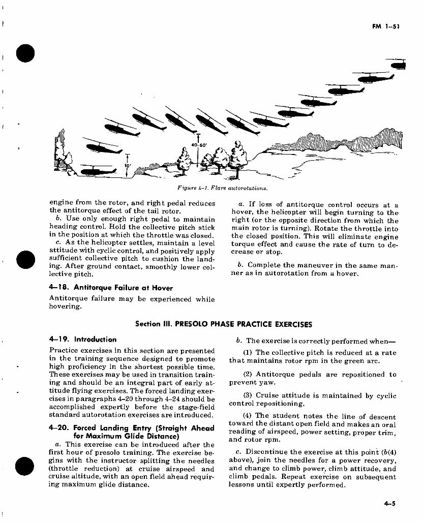
Figure U-l. Fiare autorotations.
engine from the rotor, and right pedal reduces the antitorque effect of the tail rotor.
b. Use only enough right pedal to maintain heading control. Hold the collective pitch stick in the position at which the throttle was closed.
c. As the helicopter settles, maintain a level attitude with cyclic control, and positively apply sufficient collective pitch to cushion the land- ing. After ground contact, smoothly lower col- lective pitch.
4—18. Antitorque Failure at Hover
Antitorque failure may be experienced while hovering.
a. If loss of antitorque control occurs at a hover, the helicopter will begin turning to the right (or the opposite direction from which the main rotor is turning). Rotate the throttle into the closed position. This will eliminate engine torque effect and cause the rate of turn to de- crease or stop.
b. Complete the maneuver in the same man- ner as in autorotation from a hover.
Section III. PRESOLO PHASE PRACTICE EXERCISES
4-19. Introduction
Practice exercises in this section are presented in the training sequence designed to promote high proficiency in the shortest possible time. These exercises may be used in transition train- ing and should be an integral part of early at- titude flying exercises. The forced landing exer- cises in paragraphs 4-20 through 4-24 should be accomplished expertly before the stage-field standard autorotation exercises are introduced.
4—20. Forced Landing Entry (Straight Ahead for Maximum Glide Distance)
a. This exercise can be introduced after the first hour of presolo training. The exercise be- gins with the instructor splitting the needles (throttle reduction) at cruise airspeed and cruise altitude, with an open field ahead requir- ing maximum glide distance.
b. The exercise is correctly performed when—
(1) The collective pitch is reduced at a rate that maintains rotor rpm in the green arc.
(2) Antitorque pedals are repositioned to prevent yaw.
(3) Cruise attitude is maintained by cyclic control repositioning.
(4) The student notes the line of descent toward the distant open field and makes an oral reading of airspeed, power setting, proper trim, and rotor rpm.
c. Discontinue the exercise at this point (6(4) above), join the needles for a power recovery, and change to climb power, climb attitude, and climb pedals. Repeat exercise on subsequent lessons until expertly performed.
4-5
FM 1-51
4—21. Forced Landing Entry (Straight Ahead for Shortened Glide Distance)
a. This exercise can be introduced im- mediately after completion of the maximum glide exercise (para 4-20). The exercise begins with the instructor splitting the needles (throt- tle reduction) at cruise airspeed and cruise al- titude, having an open field close in ahead which requires a steep angle of glide.
b. The exercise is correctly performed when— (1) Collective pitch is reduced at a rate that
will maintain rotor rpm in the green arc. (2) Antitorque pedals are repositioned in
the amount required to prevent yaw. (3) Attitude is raised promptly to a point
above the normal deceleration attitude and held until the airspeed approaches a value approxi- mately 25 percent below slow cruise airspeed. (This will result in a steep angle of descent.)
(4) As the airspeed "reaches the value in (3) above, the attitude is rotated to (or near) the slow cruise attitude which will hold this airs- peed (in (3) above) constant.
(5) The student notes the line of descent toward the close-in open field and makes an oral reading of airspeed, power setting, and rotor rpm.
c. Discontinue the exercise at this point (5(5) above), and execute a power recovery. Assume an acceleration attitude, add climb power, and reposition the pedals for climb. As airspeed ap- proaches the normal climb speed, rotate to the normal climb speed attitude.
d. During subsequent dual periods, forced landing entries requiring maximum glide dis- tance should be alternated with those requiring shortened glide distance. New autorotation ex- ercises should not be attempted until these two basic drills are perfected.
4—22. Forced Landing Entry (From Downwind Heading With Turn)
a. This exercise can be introduced im- mediately after completion of the straight ahead autorotation entry exercises. The exer- cise begins with the instructor splitting the needles (throttle reduction) at cruise airspeed and cruise altitude, while flying downwind and having an open field to the left or right.
b. The exercise is properly accomplished when—
(1) Collective pitch is reduced at a rate that will maintain rotor rpm.
(2) Antitorque pedals are repositioned in the amount required to prevent yaw.
(3) Cruise attitude is held during operations (1) and (2) above.
(4) A normal bank is entered (left or right) with lateral cyclic control holding cruise at- titude.
(5) As the bank is established, the attitude is changed to slow cruise, providing deceleration lift for turning power.
c. The exercise is completed upon the rotation of attitude at 6(5) above without regard to the degree of turn accomplished. Discontinue the exercise by removing bank and making a power recovery.
d. In subsequent dual periods, all three entry exercises should be given at least once during each period, so as to develop split second accu- racy in performing each of these autorotation entry maneuvers.
4—23. Power Recovery
а. Power recovery is a performance sequence used to discontinue autorotation and reestab- lish normal flight. In practice it usually is used to establish a climb, although the same proce- dure may be used to establish a cruise or normal descent.
б. The power recovery is correctly performed when—
(1) The engine tachometer needle is joined to the rotor tachometer needle by use of throt- tle.
(2) Airspeed is cross-checked. If airspeed is below normal climb airspeed, rotate attitude to an accelerating attitude (usually to a normal takeoff attitude). If airspeed is at or above nor- mal climb airspeed, rotate attitude to a normal climb attitude (usually the same as slow cruise attitude).
(3) Power is increased to the published climb power setting by increasing collective pitch and cross-checking rotor and engine rpm during the power application.
4—24. Termination With Power
а. Termination with power is an exercise se- quence used to terminate an autorotation at a hover.
б. The terminate-with-power exercise is cor- rectly performed when—
(1) At 100 feet, the engine and rotor tachometer needles are joined.
(2) The attitude is smoothly rotated to a normal decelerating attitude or level landing attitude.
(3) At approximately 15 to 25 feet, power is increased to arrive at the accepted hovering
4-6
FM 1-51
height by increasing collective pitch and cross- checking normal rpm.
(4) The decelerating or landing attitude and heading are held until all forward motion is stopped.
(5) A stationary hover is established.
4—25. Basic (Standard) Autorotation
a. The basic autorotation is a by-the-numbers (1-2-3) drill. It is a basic exercise which is pre- planned and programed throughout. Any devia- tion from the programed basic autorotation se- quence published for a particular helicopter will result in something other than a basic autorota- tion. The standard autorotation differs from the basic autorotation only in that airspeed may be altered at the entry point to assure a landing on the practice area. In the basic autorotation, the programed procedure is adhered to or the man- euver is aborted.
b. This maneuver has great training value and should be performed (unassisted) by all stu- dents prior to solo. Since the basic autorotation is programed throughout and includes a landing on a large smooth area which permits a touch- down with a variable ground run, it is unsuita- ble for introductory work in forced landing au- torotations. Therefore, the basic autorotation is usually introduced after the student is profi- cient in the forced landing entry series, the power recovery, and the termination with power (para 4-19 to 4-24).
c. The basic autorotation is correctly accomp- lished when—
(1) At flight altitude, usually 700 feet, a turn to final approach leg is accomplished, re- sulting in a good track, trimmed flight, steady altitude, and cruise airspeed.
(2) Just prior to entry, a slip is optional for crosswind correction.
(3) Power is reduced to the minimum while holding cniise attitude, with pedals repositioned to prevent yaw. (The wrist is bent inward during the collective pitch reduction. Then the throttle is eased off to engine flight idle.)
(4) An oral cross-check is made, including the actual airspeed and rotor rpm in the green (or yellow, as the case may be).
(5) Attitude is rotated to the slow cruise at- titude.
Note. Procedures (3), (4), and (5) are accomplished slowly and smoothly in some helicopters; in others, the order is changed to combine (3) and (5), with (4) accomplished last.
(6) With collective pitch positioned to main- tain rotor rpm in the green (usually on the down
stop), slow cruise attitude is cross-checked and held with the helicopter tracking in line with the touchdown lane. The nose will tend to lower as airspeed approaches the slow cruise value, requiring cyclic repositioning rearward to hold the slow cruise attitude steady.
Note. The center of attention must be on attitude con- trol throughout the maneuver; cross-check everything else outward from this reference center.
(7) With airspeed just reaching slow cruise value (or that prescribed) at approximately 100 feet, an oral cross-check is made, calling off: “Airspeed ( ), rotor in the green.”
(8) At 100 feet (if the groundspeed is not too slow and provided airspeed is at slow cruise value or higher), the attitude is progressively rotated toward the normal deceleration at- titude. (A slip is required below 50 feet for crosswind correction.)
(9) At the agreed height (usually 10 to 20 feet), an initial collective pitch application is made in the amount and at a rate that will be felt as added lift.
Note. For helicopters requiring an excessive nose- high decelerating attitude, the nose is progressively rotated toward the landing attitude at this point.
(10) A firm, positive collective pitch is ap- plied when ground contact is imminent. This will reduce the rate of descent and cause the helicopter to almost parallel the ground for a touchdown two helicopter lengths ahead.
(11) Collective pitch is used in a manner to cause light ground contact of the wheels or skid gear, and then to gradually add the full helicop- ter weight on the landing gear.
(12) The fuselage is parallel to and over the center line of the lane throughout (9) and (10) above, yielding a ground run of from one to five helicopter lengths, depending upon the prevail- ing atmospheric conditions.
4—26. Forced Landing Autorotation
The information contained in this paragraph is applicable to most helicopters. For airspeeds, see appropriate operator’s handbooks.
a. The forced landing autorotation to a pre- determined spot landing is a highly skilled man- euver, usually performed by advanced students or perfected in postgraduate training. Proce- dures vary in each type helicopter. However, portions of this information may be applied to most helicopters.
b. A study of the autorotation chart in figure 4-2 shows typical rates of descent for the vari- ous airspeeds for steady state autorotation.
4-7
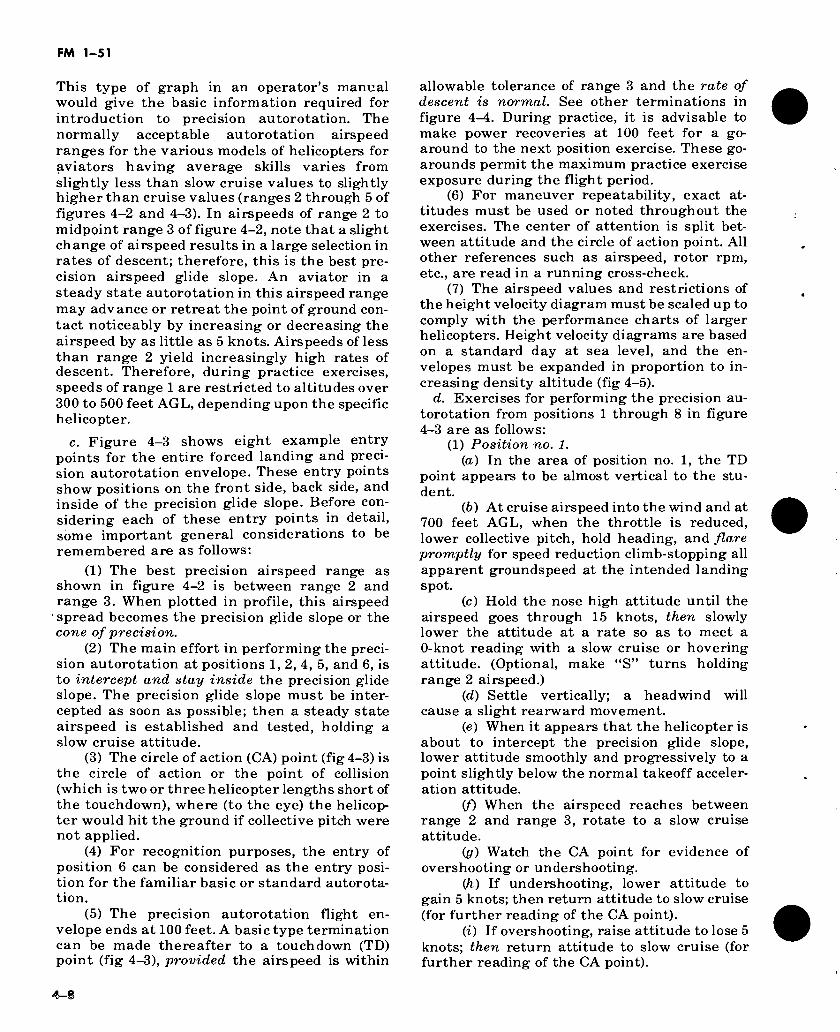
FM 1-51
This type of graph in an operator’s manual would give the basic information required for introduction to precision autorotation. The normally acceptable autorotation airspeed ranges for the various models of helicopters for aviators having average skills varies from slightly less than slow cruise values to slightly higher than cruise values (ranges 2 through 5 of figures 4-2 and 4-3). In airspeeds of range 2 to midpoint range 3 of figure 4-2, note that a slight change of airspeed results in a large selection in rates of descent; therefore, this is the best pre- cision airspeed glide slope. An aviator in a steady state autorotation in this airspeed range may advance or retreat the point of ground con- tact noticeably by increasing or decreasing the airspeed by as little as 5 knots. Airspeeds of less than range 2 yield increasingly high rates of descent. Therefore, during practice exercises, speeds of range 1 are restricted to altitudes over 300 to 500 feet AGL, depending upon the specific helicopter.
c. Figure 4-3 shows eight example entry points for the entire forced landing and preci- sion autorotation envelope. These entry points show positions on the front side, back side, and inside of the precision glide slope. Before con- sidering each of these entry points in detail, some important general considerations to be remembered are as follows:
(1) The best precision airspeed range as shown in figure 4-2 is between range 2 and range 3. When plotted in profile, this airspeed spread becomes the precision glide slope or the cone of precision.
(2) The main effort in performing the preci- sion autorotation at positions 1, 2, 4, 5, and 6, is to intercept and stay inside the precision glide slope. The precision glide slope must be inter- cepted as soon as possible; then a steady state airspeed is established and tested, holding a slow cruise attitude.
(3) The circle of action (CA) point (fig 4-3) is the circle of action or the point of collision (which is two or three helicopter lengths short of the touchdown), where (to the eye) the helicop- ter would hit the ground if collective pitch were not applied.
(4) For recognition purposes, the entry of position 6 can be considered as the entry posi- tion for the familiar basic or standard autorota- tion.
(5) The precision autorotation flight en- velope ends at 100 feet. A basic type termination can be made thereafter to a touchdown (TD) point (fig 4-3), provided the airspeed is within
allowable tolerance of range 3 and the rate of descent is normal. See other terminations in figure 4-4. During practice, it is advisable to make power recoveries at 100 feet for a go- around to the next position exercise. These go- arounds permit the maximum practice exercise exposure during the flight period.
(6) For maneuver repeatability, exact at- titudes must be used or noted throughout the exercises. The center of attention is split bet- ween attitude and the circle of action point. All other references such as airspeed, rotor rpm, etc., are read in a running cross-check.
(7) The airspeed values and restrictions of the height velocity diagram must be scaled up to comply with the performance charts of larger helicopters. Height velocity diagrams are based on a standard day at sea level, and the en- velopes must be expanded in proportion to in- creasing density altitude (fig 4-5).
d. Exercises for performing the precision au- torotation from positions 1 through 8 in figure 4-3 are as follows:
(1) Position no. 1. (a) In the area of position no. 1, the TD
point appears to be almost vertical to the stu- dent.
(b) At cruise airspeed into the wind and at 700 feet AGL, when the throttle is reduced, lower collective pitch, hold heading, and flare promptly for speed reduction climb-stopping all apparent groundspeed at the intended landing spot.
(c) Hold the nose high attitude until the airspeed goes through 15 knots, then slowly lower the attitude at a rate so as to meet a 0-knot reading with a slow cruise or hovering attitude. (Optional, make “S” turns holding range 2 airspeed.)
(d) Settle vertically; a headwind will cause a slight rearward movement.
(e) When it appears that the helicopter is about to intercept the precision glide slope, lower attitude smoothly and progressively to a point slightly below the normal takeoff acceler- ation attitude.
(f) When the airspeed reaches between range 2 and range 3, rotate to a slow cruise attitude.
(g) Watch the CA point for evidence of overshooting or undershooting.
(/i) If undershooting, lower attitude to gain 5 knots; then return attitude to slow cruise (for further reading of the CA point).
(i) If overshooting, raise attitude to lose 5 knots; then return attitude to slow cruise (for further reading of the CA point).
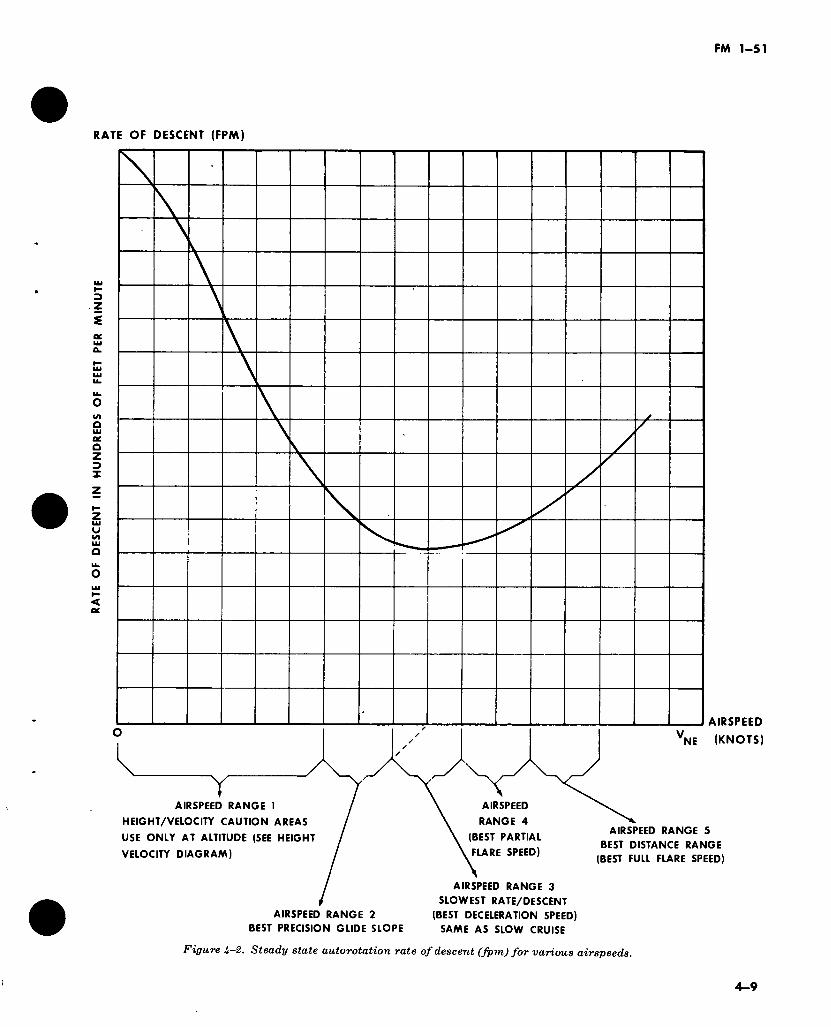
RA
TE
OF
DE
SC
EN
T
IN
HU
ND
RE
DS
OF
FE
ET
PE
R
MIN
UT
E
FM 1-51
RATE OF DESCENT (FPM)
Y AIRSPEED
RANGE 4
(BEST PARTIAL
FLARE SPEED)
AIRSPEED
VNE (KNOTS)
AIRSPEED RANGE 1
HEIGHT/VELOCITY CAUTION AREAS
USE ONLY AT ALTITUDE (SEE HEIGHT
VELOCITY DIAGRAM)
AIRSPEED RANGE 5
BEST DISTANCE RANGE
(BEST FULL FLARE SPEED)
AIRSPEED RANGE 2
BEST PRECISION GLIDE SLOPE
AIRSPEED RANGE 3
SLOWEST RATE/DESCENT
(BEST DECELERATION SPEED)
SAME AS SLOW CRUISE
Figure U-2. Steady state autorotation rate of descent (fpm) for various airspeeds.
4-9
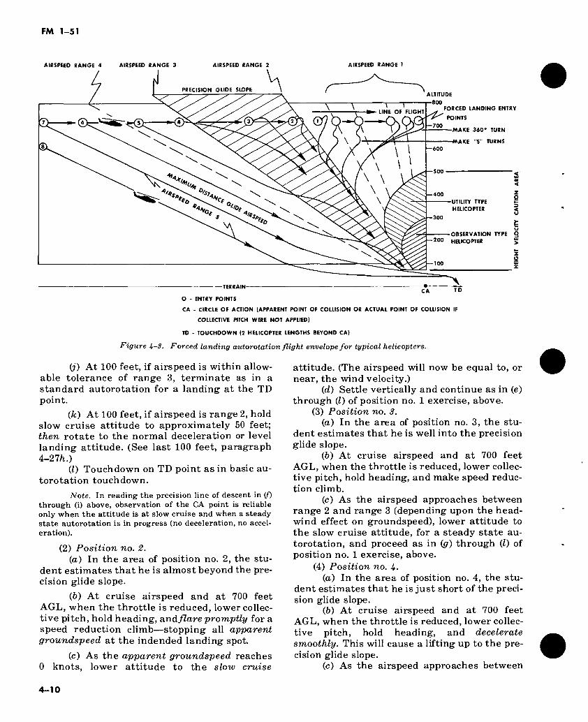
FM 1-51
AIRSPEED RANGE 4 AIRSPEED RANGE 3 AIRSPEED RANGE 2 AIRSPEED RANGE 1
ALTITUDE S PRECISION GLIDE SLOPE
800
LINE OF FLIGHT
700
600
S00
400
Of Of A>*. 300
200
FORCED LANDING ENTRY
POINTS
MAKE 360® TURN
MAKE "S" TURNS
2' « 4
Z g UTILITY TYPE |
HELICOPTER 4
OBSERVATION TYPE 2
HELICOPTER >
-TERRAIN- CA TD
O - ENTRY POINTS
CA - CIRCLE OF ACTION (APPARENT POINT OF COLLISION OR ACTUAL POINT OF COLLISION IF
COLLECTIVE PITCH WERE NOT APPLIED)
TD - TOUCHDOWN (2 HELICOPTER LENGTHS BEYOND CA)
Figure .4-5. Forced landing autorotation flight envelope for typical helicopters.
(j) At 100 feet, if airspeed is within allow- able tolerance of range 3, terminate as in a standard autorotation for a landing at the TD point.
(k) At 100 feet, if airspeed is range 2, hold slow cruise attitude to approximately 50 feet; then rotate to the normal deceleration or level landing attitude. (See last 100 feet, paragraph 4-27Ä.)
(l) Touchdown on TD point as in basic au- torotation touchdown.
Note. In reading the precision line of descent in (f) through (i) above, observation of the CA point is reliable only when the attitude is at slow cruise and when a steady state autorotation is in progress (no deceleration, no accel- eration).
(2) Position no. 2. (а) In the area of position no. 2, the stu-
dent estimates that he is almost beyond the pre- cision glide slope.
(б) At cruise airspeed and at 700 feet AGL, when the throttle is reduced, lower collec- tive pitch, hold heading, andflare promptly for a speed reduction climb—stopping all apparent groundspeed at the indended landing spot.
(c) As the apparent groundspeed reaches 0 knots, lower attitude to the slow cruise
attitude. (The airspeed will now be equal to, or near, the wind velocity.)
(d) Settle vertically and continue as in (e) through (Z) of position no. 1 exercise, above.
(3) Position no. 3. (а) In the area of position no. 3, the stu-
dent estimates that he is well into the precision glide slope.
(б) At cruise airspeed and at 700 feet AGL, when the throttle is reduced, lower collec- tive pitch, hold heading, and make speed reduc- tion climb.
(c) As the airspeed approaches between range 2 and range 3 (depending upon the head- wind effect on groundspeed), lower attitude to the slow cruise attitude, for a steady state au- torotation, and proceed as in (p) through (Z) of position no. 1 exercise, above.
(4) Position no. U- (а) In the area of position no. 4, the stu-
dent estimates that he is just short of the preci- sion glide slope.
(б) At cruise airspeed and at 700 feet AGL, when the throttle is reduced, lower collec- tive pitch, hold heading, and decelerate smoothly. This will cause a lifting up to the pre- cision glide slope.
(c) As the airspeed approaches between
4-10
FM 1-51
range 2 and range 3 (depending upon the head- wind effect on ground speed), lower attitude to the slow cruise attitude, for a steady state au- torotation, and proceed as in (p) through (l) of position no. 1 exercise, above.
Note. Exercise no. 4 is the example to use when demonstrating an ideal precision autorotation.
(5) Position no. 5. (a) In the area of position no. 5, the stu-
dent estimates that he is well short of the preci- sion glide slope.
(b) At cruise airspeed and at 700 feet when the throttle is reduced, lower collective pitch, hold heading, cruise attitude, and rotor rpm for best distance. (Hold crab, rather than slip, for best distance.)
(c) When it appears that the precision glide slope is just ahead, do a partial flare smoothly. This will cause lifting up to the preci- sion glide slope.
id) As airspeed approaches between range 2 and range 3, rotate attitude to slow cruise for a steady state autorotation and pro- ceed as in (p) through (0 of position no. 1 exer- cise, above.
(6) Position no. 6. (a) In the area of position no. 6, the stu-
dent estimates that he is almost too far back for interception of the precision glide slope.
(b) He proceeds as in position no. 5 exer- cise with possible interception of the precision glide slope further down the line of descent. However, he may decide to proceed as in posi- tion no. 7.
(7) Position No. 7. (а) In the area of position no. 7, the stu-
dent estimates that he cannot intercept the pre- cision glide slope.
(б) At cruise airspeed and at 700 feet AGL when the throttle is cut, lower collective pitch, and hold heading and cruise attitude for best distance.
(c) The line of descent appears to be a spot well short of the TD point.
(d) At approximately 200 feet, begin a smooth lifting partial flare, converting speed to lift. This will change the line of descent toward the TD point.
(e) By regulating the rate and amount of deceleration from 200 feet on, a basic type ter- mination can be made at the TD point (See fig- ure 4-4 for landing conditions.)
(8) Position No. 8. (a) This exercise is identical to position
no. 7 exercise except that the entry is set up
farther away from the precision glide slope than it was at no. 7.
(6) The line of descent appears to be to a point 100 feet (or more) short of the normal CA point.
(c) Hold best distance attitude, rotor rpm, and pedal trim. Upon reaching 40 to 60 feet al- titude, execute a full flare which is regulated in rate and amount of attitude rotation, so as to arrive at the TD point at the end of the flare.
(d) Allow the helicopter to settle to 15 to 20 feet, apply initial collective pitch, rotate at- titude to level landing attitude, and apply a firm positive collective pitch in the amount and at a rate necessary to cushion the landing.
4—27. That Last 100 Feet
For purposes of clarity, assume that the autoro- tation ends at 100 feet and that the power-off landing procedure begins there. The accepted method of executing of power-off landing (for fixed and rotary wing aircraft) is to obtain a smooth trade-off of airspeed for lift during the last 100 feet. Ideally, beginning at 100 feet, airs- peed is converted to additional lift by deceleration (c(2) below). The decleration is so timed and applied that the rate of descent and the forward speed are reduced just before touchdown to the slowest rates possible for the existing conditions.
a. Potential energy available for power-off landing. At 100 feet, the pilot must begin spend- ing stored flight energies; i.e., the forward veloc- ity of the helicopter and, just before touchdown, the rotational energy of the main rotor. At 100 feet, he can predict with accuracy the amount of potential energy (decleration or cyclic lifting power) available for the power-off landing. He can also predict the effectiveness of applying collective pitch to cushion the touchdown.
b. Reducing the Rate of Descent and Slowing the Ground Speed. All the heavy aerodynamic work of reducing the rate of descent and slowing the groundspeed should be a result of the pilot’s effecting some form of deceleration, down to ap- proximately 15 feet. Thereafter, his use of col- lective pitch further slows (at times, delays) the descent and then cushions the touchdown. See figure A-A for predictable conditions for the power-off landing.
c. Terms and Definitions. The following terms and definitions should be understood for the discussion of power-off landings in succeeding paragraphs.
(1) Attitude rotation—A preplanned or
4-11
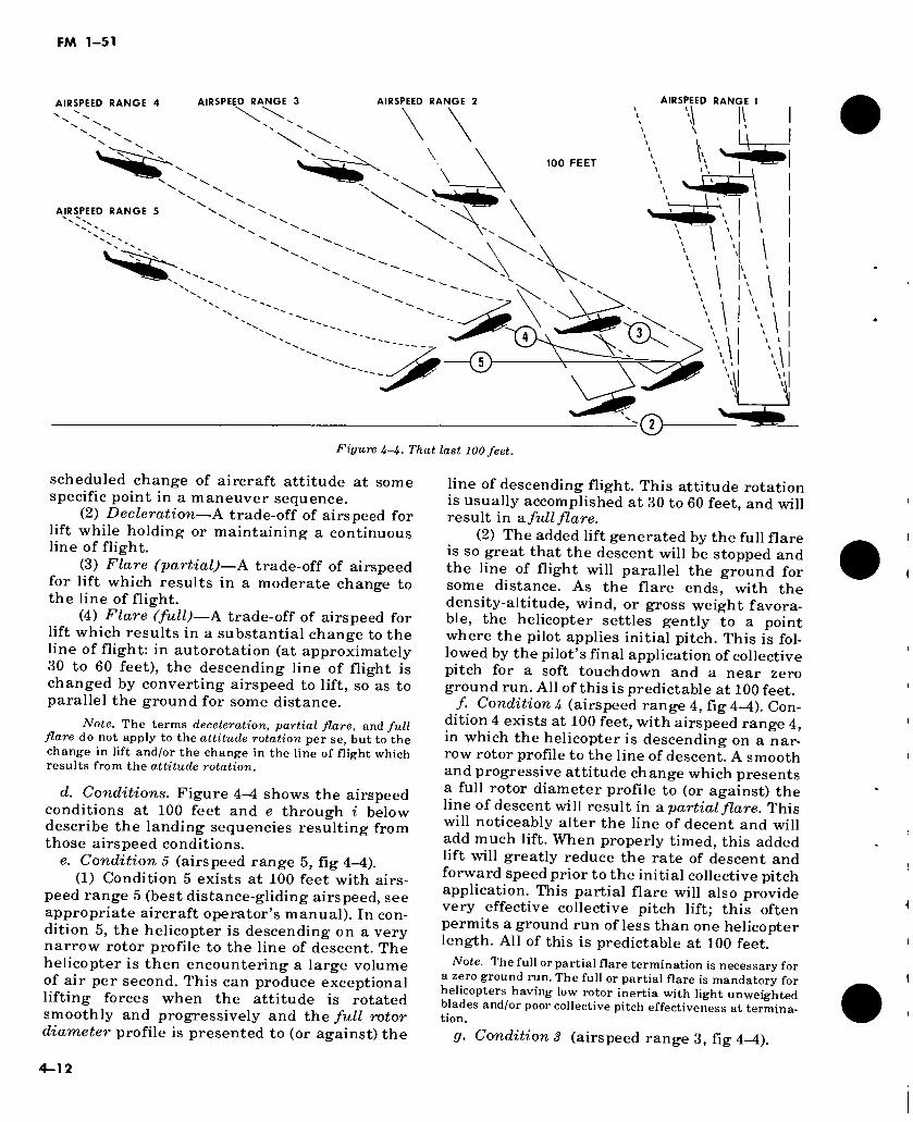
FM 1-51
AIRSPEED RANGE 4 AIRSPEED RANGE 3 AIRSPEED RANGE 2 AIRSPEED RANGE 1
100 FEET
U AIRSPEED RANGE 5
\ \ \ \ \ \
\ \ \ V
\ \
W \
Figure U-U. That last 100 feet.
scheduled change of aircraft attitude at some specific point in a maneuver sequence.
(2) Decleration—A trade-off of airspeed for lift while holding or maintaining a continuous line of flight.
(3) Flare (partial)—A trade-off of airspeed for lift which results in a moderate change to the line of flight.
(4) Flare (full)—A trade-off of airspeed for lift which results in a substantial change to the line of flight: in autorotation (at approximately 30 to 60 feet), the descending line of flight is changed by converting airspeed to lift, so as to parallel the ground for some distance.
Note. The terms deceleration, partial flare, and full flare do not apply to the attitude rotation per se, but to the change in lift and/or the change in the line of flight which results from the attitude rotation.
d. Conditions. Figure 4^4 shows the airspeed conditions at 100 feet and e through i below describe the landing sequencies resulting from those airspeed conditions.
e. Condition 5 (airspeed range 5, fig 4-4). (1) Condition 5 exists at 100 feet with airs-
peed range 5 (best distance-gliding airspeed, see appropriate aircraft operator’s manual). In con- dition 5, the helicopter is descending on a very narrow rotor profile to the line of descent. The helicopter is then encountering a large volume of air per second. This can produce exceptional lifting forces when the attitude is rotated smoothly and progressively and the full rotor diameter profile is presented to (or against) the
line of descending flight. This attitude rotation is usually accomplished at 30 to 60 feet, and will result in a full flare.
(2) The added lift generated by the full flare is so great that the descent will be stopped and the line of flight will parallel the ground for some distance. As the flare ends, with the density-altitude, wind, or gross weight favora- ble, the helicopter settles gently to a point where the pilot applies initial pitch. This is fol- lowed by the pilot’s final application of collective pitch for a soft touchdown and a near zero ground run. All of this is predictable at 100 feet.
/. Condition U (airspeed range 4, fig 4-^4). Con- dition 4 exists at 100 feet, with airspeed range 4, in which the helicopter is descending on a nar- row rotor profile to the line of descent. A smooth and progressive attitude change which presents a full rotor diameter profile to (or against) the line of descent will result in a partial flare. This will noticeably alter the line of decent and will add much lift. When properly timed, this added lift will greatly reduce the rate of descent and forward speed prior to the initial collective pitch application. This partial flare will also provide very effective collective pitch lift; this often permits a ground run of less than one helicopter length. All of this is predictable at 100 feet.
Note. The full or partial flare termination is necessary for a zero ground run. The full or partial flare is mandatory for helicopters having low rotor inertia with light unweighted blades and/or poor collective pitch effectiveness at termina- tion.
g. Condition 3 (airspeed range 3, fig 4-4).
4-12
FM 1-51
(1) Condition 3 exists at 100 feet, with airs- peed range 3, in which the helicopter is descend- ing on slightly less than a full rotor diameter profile to the line of descent; translational lift is near maximum effect and the rate of descent is minimum. The pilot should know that a smooth and progressive rotation of attitude which pres- ents a full rotor diameter profile to (or against) the line of descent will result in an effective deceleration.
(2) This deceleration, while not noticeably changing the line of descent, will reduce the rate of descent and the forward speed to a point where collective pitch energy will be quite effec- tive. When the deceleration is timed correctly, the descent is often stopped completely when initial pitch is applied by the pilot. This still leaves adequate pitch to delay and then cushion the touchdown (when wind, density altitude, or weight are favorable). This should result in a ground run of less than two lengths. All of this is predictable at 100 feet.
h. Condition 2 (airspeed range 2, fig. 4-4). (1) Condition 2 exists at 100 feet, with airs-
peed range 2, when the helicopter is descending on nearly a. full rotor diameter profile. The pilot knows or should know that nothing will be gained by an attitude rotation; that he should hold a steady attitude to maintain the speed, at least down to 50 feet; and that, of the five condi- tions, Condition 2 will give the longest ground run. Therefore, at about 50 feet he should begin a progressive attitude change until a slight rearward tilt of the rotor occurs just prior to his application of collective pitch. The attitude change will not supply additional lift, but it will add a rearward component of lift during his pitch application. This will help slow and shor- ten the ground run.
(2) It is predictable that, having no effec- tive deceleration lift in progress (during the last 100 feet), the application of collective pitch alone will not provide sufficient lifting and braking action to have appreciable effect in delaying the touchdown and slowing the ground run. The ground run will be approximately three to four lengths. All of this is predictable at 100 feet.
(3) The hidden danger in Condition 2 lies in the frequency of occurrence of this condition. Another consideration is that Condition 2 falls on the borderline of the height-velocity diagram. Often a wind gradient and/or high density al- titude condition, can then cause an increase in the rate of descent, thus increasing the lift de- mands on the collective pitch application. The resulting accident summary usually states that the damage was caused by a late and insuffi-
cient application of collective pitch. Actually, the error occurred earlier—at 100 feet; it was due to a lack of knowledge, cross-check, projec- tion, and prediction. When Condition 2 is per- formed knowledgeably, with normal atmos- pheric and gross weights, it is considered a SAFE operation.
i. Condition 1 (airspeed range 1, fig 4^4). Con- dition 1 falls in the restricted areas of the height/velocity diagram. It exists at 100 feet, with airspeed range 1, when the helicopter is descending on a full rotor diameter profile to the line of descent. There is a high sink rate; no deceleration lift is possible. Due to a wind gra- dient, gusts, or wind shift, this condition may suddenly occur in the last 100 feet of descent. The entire rate of descent must then be stopped by the application of collective pitch alone. Usu- ally, the lift produced is insufficient for safe landings. Condition 1 may also cause obvious or hidden damage to the helicopter due to hard landings. Such damage might be acceptable for an actual engine failure, but it is never accepta- ble for normal training practice and a termina- tion with power is necessary. All of this is pre- dictable at 100 feet.
4—28. Height/velocity diagram.
a. A typical height/velocity diagram or “dead man’s curve” is shown in B, figure 4-5. The re- stricted areas carry the warning “Avoid con- tinuous operations—engine failure while operating within these caution areas is likely to result in damage to the helicopter.”
b. Area (A) of diagram A in figure 4-5 is com- puted from engineering data, with the following factors included:
(1) Rate of descent required to drive the rotor in autorotation, for each 10-knot incre- ment of airspeed (from 0 through red line or top speed) for the specific helicopter configuration. See diagram B, figure 4-5.
(2) Rotor inertia characteristics or the rotor rpm decay rate, from the moment of engine fail- ure or until engine failure cues become availa- ble to the pilot. The pilot reaction time must be added after the cues become available. It is also based on rotor rpm decay rate experienced while sufficient vertical descent is achieved to drive the rotor.
(3) Translational lift values and sink rates for each height ¡velocity condition, with the re- sulting rotor rpm and “pitch pull” energy then available for cushioning ground impact.
(4) Designed stress limitations of the land-
4-13
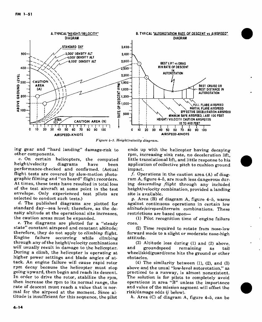
FM 1-51
A. TYPICAL"HEIGHT /VELOCITY” DIAGRAM
B. TYPICAL "AUTOROTATION RATE OF DESCENT vs AIRSPEED" DIAGRAM
BEST LIFT vs DRAG MIN RATE OF DESCENT
IN AUTOROTATION
STANDARD DAY 3,400-
2,000' DENSITY ALT -4,000'DENSITY ALT ^6,000' DENSITY ALT
500 3,100
2,800-
400 2,500-
2.200-
CAUTION AREA
(A)
-‘300 ~ 1,900-
= 1,600-1 1 \ I I 200 5 1,300-
/ / / o 1,000- Li_ o //./
/// < 100 /// 500-
AREA CAUTION AREA (B)
I 1 I 1 I ) 70 80 90 100
(C
20 30 20 30 90 "H
40 50 60
AIRSPEED-KNOTS
BEST CRUISE OR BEST DISTANCE IN AUT0R0TATI0N
FULL FLARE AIRSPEED PARTIAL FLARE AIRSPEED
EFFECTIVE DECELERATION AIRSPEED MINIMUM SAFE AIRSPEED, LAST 100 FEET
HEIGHT/VELOCITY CAUTION AIRSPEEDS 10 TO 400 FEET r r
40 50 60 70 80 AIRSPEED-KNOTS
100
Figure U-5. Heightjvelocity diagram.
ing gear and “hard landing” damage-risk to other components.
c. On certain helicopters, the computed height/velocity diagrams have been performance-checked and confirmed. (Actual flight tests are covered by slow-motion photo- graphic filming and “on board” flight recorders. At times, these tests have resulted in total loss of the test aircraft at some point in the test envelope. Only experienced test pilots are selected to conduct such tests.)
d. The published diagrams are plotted for standard day—sea level; therefore, as the de- nsity altitude at the operational site increases, the caution areas must be expanded.
e. The diagrams are plotted for a “steady state” constant airspeed and constant altitude; therefore, they do not apply to climbing flight. Engine failure occurring while climbing through any of the height/velocity combinations will usually result in damage to the helicopter. During a climb, the helicopter is operating at higher power settings and blade angles of at- tack. An engine failure will cause rapid rotor rpm decay because the helicopter must stop going upward, then begin and reach its descent. In order to drive the rotor, stabilize the rpm, then increase the rpm to its normal range, the rate of descent must reach a value that is nor- mal for the airpeed at the moment. Since al- titude is insufficient for this sequence, the pilot
ends up with the helicopter having decaying rpm, increasing sink rate, no deceleration lift, little translational lift, and little response to his application of collective pitch to cushion ground impact. /. Operations in the caution area (A) of diag-
ram A, figure 4-5, are much less dangerous dur- ing descending flight through any included height/velocity combination, provided a landing site is available.
g. Area (B) of diagram A, figure 4-5, warns against continuous operations in certain low altitudelairspeedlterrain combinations. These restrictions are based upon—
(1) Pilot recognition time of engine failure cues.
(2) Time required to rotate from nose-low forward mode to a slight or moderate nose-high attitude.
(3) Altitude loss during (1) and (2) above, and groundspeed remaining as tail wheel/skid/guard/cone hits the ground or other obstacles.
(4) The similarity between (1), (2), and (3) above and the usual “low-level autorotation,” as practiced to a runway, is almost nonexistent. The solution is for pilots to completely avoid operations in area “B” unless the importance and value of the mission segment will offset the risk/damage odds (j below).
h. Area (C) of diagram A, figure 4-5, can be
4-14
FM 1-51
used over open level terrain or runways where obstacle evasion or direction change is not re- quired and a short ground run is possible. This condition is similar to the usual practice low- level autorotation.
i. A helicopter pilot must complete a wide var- iety of missions, portions of which include ele- ments of risk. His career safety profile can be estimated by the percentage of time spent in high-risk flight envelopes per mission. Commer- cial pilots adjust the risk by adjusting charges to the customer, with approximate cost to the customer for a small helicopter as follows:
(1) $1.50 per minute—flight from points A to B (altitude, airspeed, and route—pilot’s choice).
(2) $2.00 per minute—flgiht from points A to B (altitude, airspeed, and route—customer’s choice).
(3) $2.50 per minute—normal lift operations at or around customer’s job site; i.e., publicity or photo work.
(4) $6.00 per minute—operational time in height/velocity caution areas.
j. The aviator should not operate in the
caution areas of height/velocity diagram unless the importance and value of the mission seg- ment will offset the risk/da.mage odds.
k. At slow airspeeds with an available land- ing site (as a general rule), the aviator should allow 300 feet for small helicopters and 500 to 600 feet for larger helicopters to set up a steady-state autorotation and complete a reasonably safe landing.
l. An engine failure (A, fig 4-5) at 10 knots, 200 feet, requires 2,700 fpm rate of descent (B, fig 4-5) to drive the rotor at normal rpm.
m. An engine failure at 20 knots (A, fig 4-5), 150 feet, requires 2,100 fpm rate of descent (B, fig 4-5) to drive the rotor at normal rpm.
n. The rates of descent in examples 1 and 2 of diagram B, figure 4-5, will not be attained; therefore, rotor rpm will decay. No deceleration lift is possible to slow the rate of descent, and rotor inertia (rpm) will be low for the collective pitch application and touchdown. These com- bined effects will increase the possibility of a hard landing and structural damage to the helicopter.
4-15
FM 1-51
CHAPTER 5
NIGHT FLYING
5-1. Preflight Inspection Since defects which are easily detected in day- light will often escape attention at night, a night preflight inspection must be very thorough. If practical, preflight inspection should be conducted during daylight hours. When conducting a preflight inspection at night, a flashlight should be used to supplement the available lighting (e.g., helicopter lights, flood lights, vehicle lights, etc.). Night inspec- tion is identical to daylight inspection except that the position lights, landing light, sear- chlight, cockpit lights, and instrument lights must be checked to determine if they are opera- tional. During the preflight—
a. Operate the position lights in the BRIGHT/FLASH BRIGHT mode until the helicopter is ready to depart the parking area.
b. Extend, if adjustable, the landing light and searchlight to the desired position and check that each light is operational. When airborne, further adjustment will be required for each light to obtain the best results for the maneuv- ers to be performed.
5-2. Uses of Light a. When ready to hover—
(1) For nontactical flight operations, turn the position light selector switch to the STEADY mode and the rotating beacon ON. To distinguish advanced maneuvers (e.g., autoro- tations) from normal approaches while in the traffic pattern, deviations from this lighting procedure may be required.
(2) Tactical conditions require operating the position lights in the DIM mode with the rotating beacon turned OFF. During shutdown, operate the position lights in the BRIGHT/FLASH BRIGHT mode with the rotat- ing beacon turned OFF. Leave the lights on until the rotor blades are tied down and the post flight inspection is completed.
b. During hovering operations at a heliport, use the landing light or searchlight to insure obstacle clearance.
c. Use care when operating the landing light
or searchlight in areas where other aircraft are operating. The light may temporarily blind another aviator if pointed directly at him.
d. The landing light or searchlight may be used to identify the helicopter position when entering or departing the traffic pattern.
e. When conducting night touchdown autoro- tations at a stagefield, turn the landing light or searchlight ON when on final approach and leave it on until termination of the maneuver or the execution of a go-around.
/. If the rotating beacon is inoperative when in flight, position lights should be operated in the flash mode.
5—3. Hovering Techniques a. Difficulty is experienced in maintaining di-
rectional control and hovering altitude at night. When hovering with the landing light or sear- chlight, ground references are available to the front and to a limited degree to each side of the helicopter. Normal technique for a hover during daylight conditions apply when hovering with the landing light or searchlight on.
b. When hovering without the aid of the land- ing light or searchlight, the position lights pro- vide the only means of illumination. Although the lighting is not bright, it is sufficient if the hover is kept below 5 feet. Under these condi- tions, a common error is to stare at a point which tends to induce vertigo. Reference points should be selected both to the front and to the sides of the helicopter. These references should be selected at varying distances from the helicopter. To avoid fixation, the eyes should be constantly shifted to scan and identify refer- ence points in all directions.
c. On some helicopters, the shadow formed by the skid from the illumination of the position lights provides a good indicator for identifying the altitude of the hover. As the helicopter as- cends, the size of the shadow will become larger and as it descends the shadow will become smal- ler. Upon establishing a 3-foot hover, reference should be made to the size of the shadow.
d. When operating with minimum lights at
5-1
FM 1-51
night, a normal tendency is to hover too fast. This situation is difficult to overcome when hovering over sod. Continuous reference must be made to the side of the helicopter to observe terrain features that will give an indication of forward speed. If hovering on a runway, the white centerline and runway lights provide a good reference for determining forward speed.
5—4 Takeoff Technique
Night takeoff procedures differ from daylight takeoff in that sufficient power must be applied to assure that an immediate climb is established as the helicopter begins to accelerate forward. The vertical speed indicator gives an indication that a positive rate of climb is established. Due to the time delay that is required to adapt to night vision after being exposed to light, avoid use of the landing light or searchlight during takeoff. Frequent reference to flight instru- ments is required during takeoff.
5—5. Approach Technique
a. The normal approach should be used at night when conditions allow. During the last 100 feet of the approach, the airspeed and rate of descent should be slightly reduced. This allows a safety margin in which actual altitude above the ground can be determined.
Warning: When terminating an approach, do not rely on the altimeter to determine height above the ground.
b. The following points should be remembered when making a night approach:
(1) When the tactical situation permits, the landing light is used during approaches.
(2) Position lights afford enough illumina- tion to see the ground from an altitude of from 3 to 5 feet.
(3) Rapid decelerations should be avoided due to the difficulty of estimating altitudes at night which may result in the tail structure of the helicopter striking the ground.
(4) When making an approch to a lighted T, the landing should be planned to terminate the approach in the upper left portion of the T. Dur- ing the approach, the apparent distance bet- ween the lights in the stem of the T provides depth perception and serves as an indicator of the approach angle that is being maintained.
(a) Prior to entry on the final approach leg, the lights forming the stem of the T appear to merge (A, fig 5-1). For the normal approach angle, the stem of the T appears approximately as at B, figure 5-1. If the distance between the lights appears to increase, the approach is
steepening or overarcing (C, fig 5-1). On a go- around and overfly of the T, the lights will ap- pear as in D, figure 5-1.
(b) Determine alinement by observing the stem of the T. If the stem points to the left of your position (E, fig 5-1), you are too far to the right of course and should correct to the left. If the stem points to the right of your position (F, fig 5-1), you are too far to the left of course and should correct to the right.
(5) The glide slope indicator is mounted on a universal joint which permits adjustments from zero to 15° above the horizontal, making it adaptable for all types of approaches. It casts three separate, colored beams of light. The top beam is amber, the center green, and the bottom red (fig 5-2). When approaching in the center of any one of the three beams, a brilliant shade of the light is seen. The green beam guides the approach and assures the aviator obstacle clearance if he stays in it (or in the amber beam above it). The red beam indicates that the av- iator is too low and may be in danger. If the helicopter is allowed to drift to the extreme edge of the approach beams, the light maybe reduced so much that all beams appear light amber. The aviator, thinking he is high (in the amber beam), may reduce collective pitch to lose altitude; and if the error is not corrected in time, premature ground contact will occur.
c. An aviator may experience difficulty in properly executing the approach, for the follow- ing reasons:
(1) Overshooting the landing point because of failure to reduce the rate of descent and for- ward airspeed.
(2) Undershooting the landing point be- cause of reduction in airspeed too quickly and failure to compensate with collective pitch to check the rate of descent. As a result, the helicopter descends almost vertically.
(3) Staring at the approach light too long, causing loss of perspective, and consequently, becoming disoriented.
5-6. Autorotations
a. Night autorotations are performed in the same manner as in daylight conditions (chap 4). Difficulty is experienced in estimating height at night. As a result, there is a tendency to apply collective pitch too soon or too late. To overcome this deficiency, make frequent observations out the side window. A tendency is to concentrate too intently on applying pitch and failing to cor- rect for drift and for yaw effect when collective pitch is applied. If the deceleration attitude be-
5-2
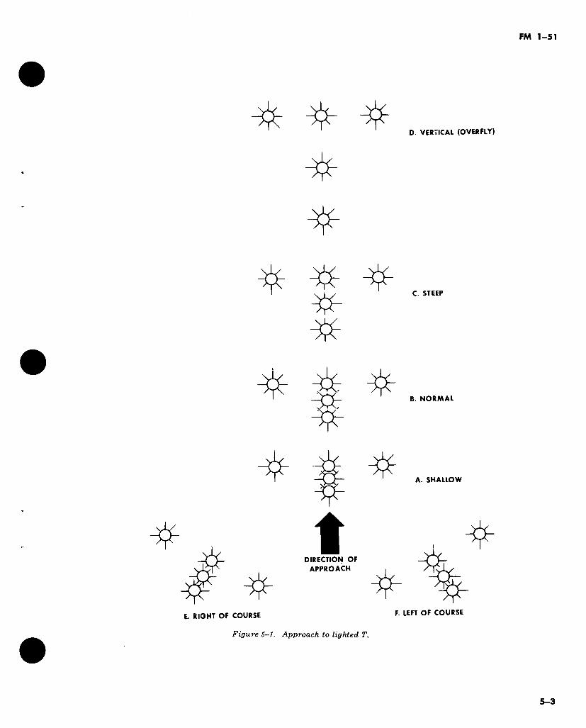
FM 1-51
D. VERTICAL (OVERFLY)
t DIRECTION OF
APPROACH
#"
^ I *
C. STEEP
B. NORMAL
A. SHALLOW
% E. RIGHT OF COURSE
Figure 5-1. Approach to lighted T.
F. LEFT OF COURSE
5-3
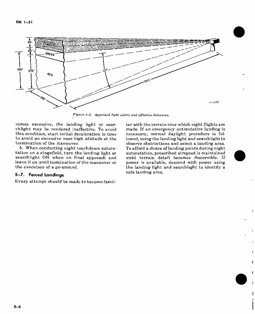
FM 1-51
300'
80’
&¡i§§$ + 60’
Wff/V
270 ffen
AS
707
Figure 5-2. Approach light colors and effective distances.
comes excessive, the landing light or sear- chlight may be rendered ineffective. To avoid this condition, start initial deceleration in time to avoid an excessive nose high attitude at the termination of the maneuver.
b. When conducting night touchdown autoro- tation on a stagefield, turn the landing light or searchlight ON when on final approach and leave it on until termination of the maneuver or the execution of a go-around.
5—7. Forced Landings
Every attempt should be made to become famil-
iar with the terrain over which night flights are made. If an emergency autorotative landing is necessary, normal daylight procedure is fol- lowed, using the landing light and searchlight to observe obstructions and select a landing area. To afford a choice of landing points during night autorotation, prescribed airspeed is maintained until terrain detail becomes discernible. If power is available, descend with power using the landing light and searchlight to identify a safe landing area.
i
i
1
1
5-4
FM 1-51
CHAPTER 6
CONFINED, REMOTE, AND UNIMPROVED AREA OPERATIONS
6-1. Basic Considerations
For the purpose of this discussion, a confined area is any area where the flight of the helicop- ter is limited in some direction by terrain or the presence of obstructions, natural or manmade. For example, a clearing in the woods, the top of a mountain, the slope of a hill, or the deck of a ship can each be regarded as a confined area.
a. Takeoffs and Landings. Takeoffs and land- ings should generally be made into the wind to obtain maximum airspeed with minimum groundspeed. Situations may arise which mod- ify this general rule.
b. Turbulence. Turbulence is defined as smal- ler masses of air moving in any direction con- trary to that of the larger airmass. Barriers on the ground and the ground itself may interfere with the smooth flow of air. This interference is transmitted to upper air levels as larger but less intense disturbances. Therefore, the greatest turbulence usually is found at low altitudes. Gusts are sudden variation in wind velocity. Normally, gusts are dangerous only in slow flight at very low altitudes. The aviator may be unaware of the gust, and its cessation may re- duce airspeed below that required to sustain flight. Gusts cannot be planned for or antici- pated. Turbulence, however, can generally be predicted. Turbulence will be found in the fol- lowing places when wind velocity exceeds 9 knots:
(1) Near the ground on the downwind side of trees, buildings, or hills. The turbulent area is always relative in size to that of the obstacle, and relative in intensity to the velocity of the wind (fig 6-1).
(2) On the ground on the immediate upwind side of any solid barrier such as leafy trees, buildings, etc. This condition is not generally dangerous unless the wind velocity is approxi- mately 17 knots or higher.
(3) In the air, over and slightly downwind of any sizable barrier, such as a hill. The size of the barrier and the wind velocity determine the height to which the turbulence extends.
(4) At low altitudes on bright sunny days
near the border of two dissimilar types of ground, such as the edge of a ramp or runway bordered by sod (fig 6-2). This type of turbulence is caused by the upward and downward passage of heated or cooled air.
6-2. Reconnaissance
A high and low reconnaissance should be con- ducted prior to landing in an unfamiliar area.
a. High Reconnaissance. The purpose of a high reconnaissance is to determine suitability of the landing area, locate barriers and estimate their wind effect, select approach and departure axis, select a point for touchdown, and plan the flightpath for approach and takeoff. Altitude, airspeed, and flight pattern for the high recon- naissance is governed by wind and terrain fea- tures, including availability of forced-landing areas. The reconnaissance should be low enough to permit study of the general area, yet not so low that attention must be divided between studying the area and avoiding obstructions to flight. It should be high enough to afford a reasonable chance of making a successful forced landing in an emergency, yet not so high that the proposed area cannot be studied adequately.
b. Low Reconnaissance. (1) Except when a running landing is
necessary, the low reconnaissance and ap- proach can often be conducted together. To ac- complish this, the aviator studies his approach path and the immediate vicinity of his selected touchdown point as he approaches; however, be- fore loss of effective translational lift, or prior to descending below the barrier, he must decide whether the landing can be completed success- fully. Never land in an area from which a suc- cessful takeoff cannot be made. The low recon- naissance should confirm what was learned from the high reconnaissance.
(2) When a running landing is contemplated because of load or high density altitude condi- tions, a “fly-by” type of low reconnaissance is made. Airspeed is adequate to maintain effec- tive translational lift at an altitude sufficient to clear all obstacles and allow the aviator to con-
6-1
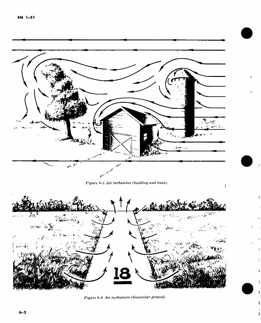
FM 1-51
r Ci ; fßf'
(4r «
esc
}
Figure 6-1. Air turbulence (building and trees).
VI
fi*
> 11 M ‘'u > i ‘ rr . . * ' ' t1* - < r?» 1^%
> • O—>1 Vs-' . * -
■K- > 1 4' K'. .
t-Wi SN
r- 1 T"*^^
\ / vr
v.v‘»^r'' \
O
18 Figure 6-2. Air turbulence (dissimilar ground).
6-2
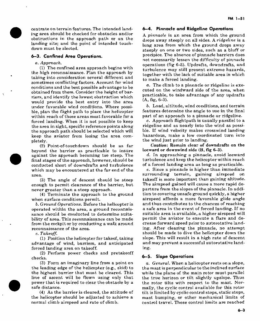
FM 1-51
centrate on terrain features. The intended land- ing area should be checked for obstacles and/or obstructions in the approach path or on the landing site; and the point of intended touch- down must be sleeted.
6-3. Confined Area Operations.
a. Approach. (1) The confined area approach begins with
the high reconnaissance. Plan the approach by taking into consideration several different and sometimes conflicting factors. Account for wind conditions and the best possible advantage to be obtained from them. Consider the height of bar- riers, and identify the lowest obstruction which would provide the best entry into the area under favorable wind conditions. Where possi- ble, plan the flight path to place the helicopter within reach of those areas most favorable for a forced landing. When it is not possible to keep the area in sight, specific reference points along the approach path should be selected which will keep the aviator from losing the area com- pletely.
(2) Point-of-touchdown should be as far beyond the barrier as practicable to insure against the approach becoming too steep. The final stages of the approach, however, should be conducted short of downdrafts and turbulence which may be encountered at the far end of the area.
(3) The angle of descent should be steep enough to permit clearance of the barrier, but never greater than a steep approach.
(4) Terminate the approach to the ground when surface conditions permit.
h. Ground Operations. Before the helicopter is operated within the area, a ground reconnais- sance should be conducted to determine suita- bility of area. This reconnaissance can be made from the cockpit or by conducting a walk around reconnaissance of the area.
c. Takeoff. (1) Position the helicopter for takeof, taking
advantage of wind, barriers, and anticipated forced landing area on takeoff.
(2) Perform power checks and pretakeoff checks.
(3) Form an imaginary line from a point on the leading edge of the helicopter (e.g., skid) to the highest barrier that must be cleared. This line of ascent will be flown using only that power that is required to clear the obstacle by a safe distance.
(4) As the barrier is cleared, the attitude of the helicopter should be adjusted to achieve a normal climb airspeed and rate of climb.
6-4. Pinnacle and Ridgeline Operations
A pinnacle is an area from which the ground drops away steeply on all sides. A ridgeline is a long area from which the ground drops away steeply on one or two sides, such as a bluff or precipice. The absence of pinnacle barriers does not necessarily lessen the difficulty of pinnacle operations (fig 6-3). Updrafts, downdrafts, and turbulence may still present extreme hazards, together with the lack of suitable area in which to make a forced landing.
a. The climb to a pinnacle or ridgeline is exe- cuted on the windward side of the area, when practicable, to take advantage of any updrafts (A, fig, 6-3).
b. Load, altitude, wind conditions, and terrain features determine the angle to use in the final part of an approach to a pinnacle or ridgeline.
c. Approach flightpath is usually parallel to a ridgeline and as nearly into the wind as possi- ble. If wind velocity makes crosswind landing hazardous, make a low coordinated turn into the wind just prior to landing.
Caution'. Remain clear of downdrafts on the leeward or downwind side (B, fig 6-3).
d. In approaching a pinnacle, avoid leeward turbulence and keep the helicopter within reach of a forced landing area as long as practicable.
e. Since a pinnacle is higher than immediate surrounding terrain, gaining airspeed on takeoff is more important than gaining altitude. The airspeed gained will cause a more rapid de- parture from the slopes of the pinnacle. In addi- tion to covering unsafe ground quickly, a higher airspeed affords a more favorable glide angle and thus contributes to the chances of reaching a safe area in the event of forced landing. If no suitable area is available, a higher airspeed will permit the aviator to execute a flare and de- crease forward speed prior to autorotative land- ing. After clearing the pinnacle, no attempt should be made to dive the helicopter down the slope. This will result in a high rate of descent and may prevent a successful autorotative land- ing.
6-5. Slope Operations
a. General. When a helicopter rests on a slope, the mast is perpendicular to the inclined surface while the plane of the main rotor must parallel the true horizon or tilt slightly upslope. Thus the rotor tilts with respect to the mast. Nor- mally, the cyclic control available for this rotor tilt is limited by cyclic control stops, static stops, mast bumping, or other mechanical limits of control travel. These control limits are reached
6-3
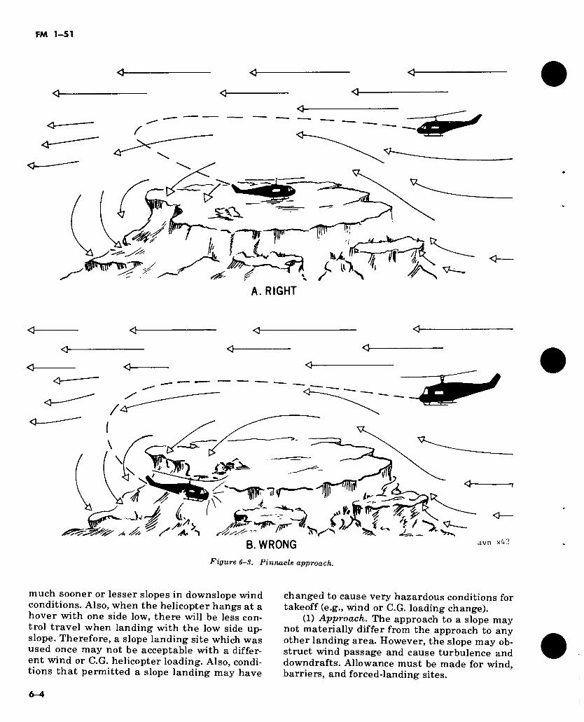
FM 1-51
SÄ.
i ipc?i A. RIGHT
<1
r- n a\
B. WRONG Figure 6-8. Pinnacle approach.
avn x£'
much sooner or lesser slopes in downslope wind conditions. Also, when the helicopter hangs at a hover with one side low, there will be less con- trol travel when landing with the low side up- slope. Therefore, a slope landing site which was used once may not be acceptable with a differ- ent wind or C.G. helicopter loading. Also, condi- tions that permitted a slope landing may have
changed to cause very hazardous conditions for takeoff (e.g., wind or C.G. loading change).
(1) Approach. The approach to a slope may not materially differ from the approach to any other landing area. However, the slope may ob- struct wind passage and cause turbulence and downdrafts. Allowance must be made for wind, barriers, and forced-landing sites.
I
6-4
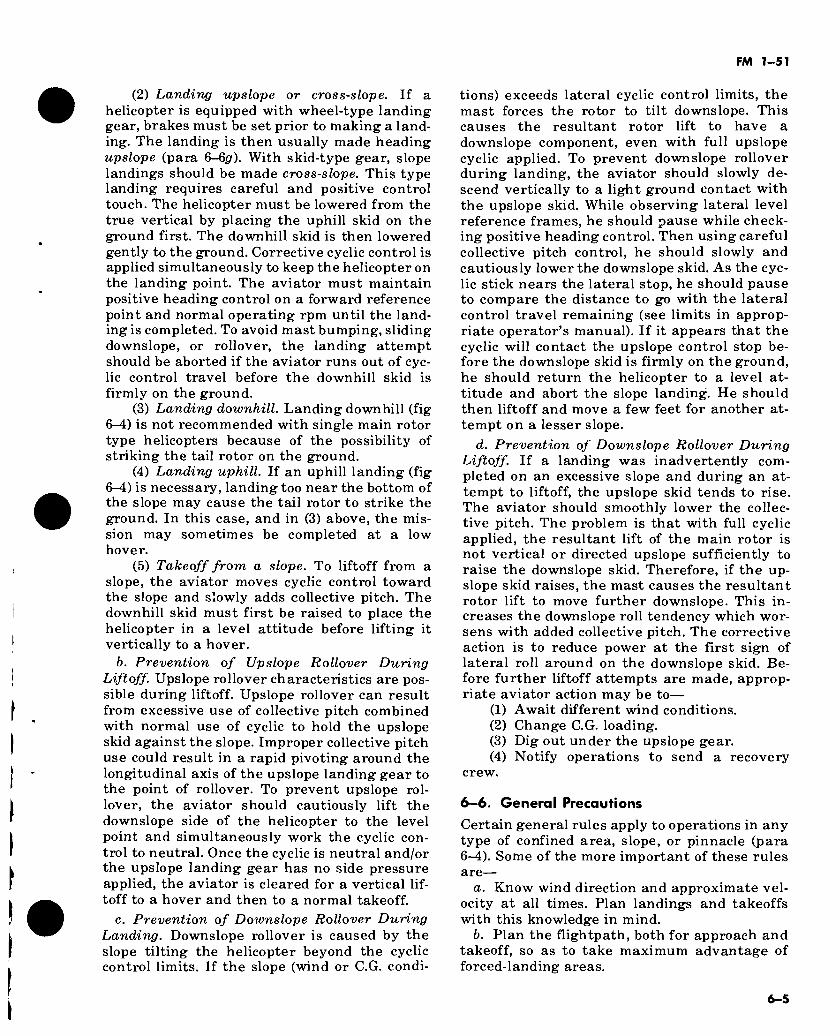
FM 1-51
(2) Landing upslope or cross-slope. If a helicopter is equipped with wheel-type landing gear, brakes must be set prior to making a land- ing. The landing is then usually made heading upslope (para 6-6*7). With skid-type gear, slope landings should be made cross-slope. This type landing requires careful and positive control touch. The helicopter must be lowered from the true vertical by placing the uphill skid on the ground first. The downhill skid is then lowered gently to the ground. Corrective cyclic control is applied simultaneously to keep the helicopter on the landing point. The aviator must maintain positive heading control on a forward reference point and normal operating rpm until the land- ing is completed. To avoid mast bumping, sliding downslope, or rollover, the landing attempt should be aborted if the aviator runs out of cyc- lic control travel before the downhill skid is firmly on the ground.
(3) Landing downhill. Landing downhill (fig 6-4) is not recommended with single main rotor type helicopters because of the possibility of striking the tail rotor on the ground.
(4) Landing uphill. If an uphill landing (fig 6-4) is necessary, landing too near the bottom of the slope may cause the tail rotor to strike the ground. In this case, and in (3) above, the mis- sion may sometimes be completed at a low hover.
(5) Takeoff from a slope. To liftoff from a slope, the aviator moves cyclic control toward the slope and slowly adds collective pitch. The downhill skid must first be raised to place the helicopter in a level attitude before lifting it vertically to a hover.
b. Prevention of Upslope Rollover During Liftoff. Upslope rollover characteristics are pos- sible during liftoff. Upslope rollover can result from excessive use of collective pitch combined with normal use of cyclic to hold the upslope skid against the slope. Improper collective pitch use could result in a rapid pivoting around the longitudinal axis of the upslope landing gear to the point of rollover. To prevent upslope rol- lover, the aviator should cautiously lift the downslope side of the helicopter to the level point and simultaneously work the cyclic con- trol to neutral. Once the cyclic is neutral and/or the upslope landing gear has no side pressure applied, the aviator is cleared for a vertical lif- toff to a hover and then to a normal takeoff.
c. Prevention of Downslope Rollover During Landing. Downslope rollover is caused by the slope tilting the helicopter beyond the cyclic control limits. If the slope (wind or C.G. condi-
tions) exceeds lateral cyclic control limits, the mast forces the rotor to tilt downslope. This causes the resultant rotor lift to have a downslope component, even with full upslope cyclic applied. To prevent downslope rollover during landing, the aviator should slowly de- scend vertically to a light ground contact with the upslope skid. While observing lateral level reference frames, he should pause while check- ing positive heading control. Then using careful collective pitch control, he should slowly and cautiously lower the downslope skid. As the cyc- lic stick nears the lateral stop, he should pause to compare the distance to go with the lateral control travel remaining (see limits in approp- riate operator’s manual). If it appears that the cyclic will contact the upslope control stop be- fore the downslope skid is firmly on the ground, he should return the helicopter to a level at- titude and abort the slope landing. He should then liftoff and move a few feet for another at- tempt on a lesser slope.
d. Prevention of Downslope Rollover During Liftoff. If a landing was inadvertently com- pleted on an excessive slope and during an at- tempt to liftoff, the upslope skid tends to rise. The aviator should smoothly lower the collec- tive pitch. The problem is that with full cyclic applied, the resultant lift of the main rotor is not vertical or directed upslope sufficiently to raise the downslope skid. Therefore, if the up- slope skid raises, the mast causes the resultant rotor lift to move further downslope. This in- creases the downslope roll tendency which wor- sens with added collective pitch. The corrective action is to reduce power at the first sign of lateral roll around on the downslope skid. Be- fore further liftoff attempts are made, approp- riate aviator action may be to—
(1) Await different wind conditions. (2) Change C.G. loading. (3) Dig out under the upslope gear. (4) Notify operations to send a recovery
crew.
6-6. General Precautions
Certain general rules apply to operations in any type of confined area, slope, or pinnacle (para 6-4). Some of the more important of these rules are—
a. Know wind direction and approximate vel- ocity at all times. Plan landings and takeoffs with this knowledge in mind.
b. Plan the flightpath, both for approach and takeoff, so as to take maximum advantage of forced-landing areas.
6-5
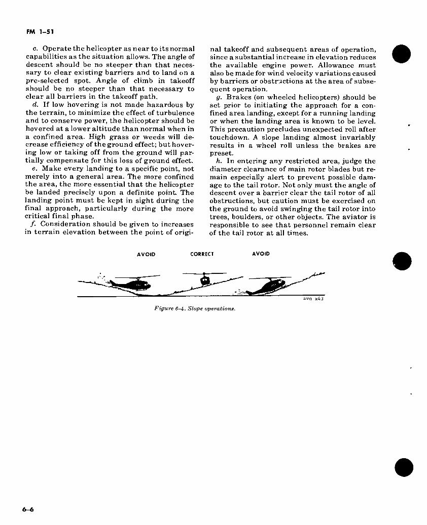
FM 1-51
c. Operate the helicopter as near to its normal capabilities as the situation allows. The angle of descent should be no steeper than that neces- sary to clear existing barriers and to land on a pre-selected spot. Angle of climb in takeoff should be no steeper than that necessary to clear all barriers in the takeoff path.
d. If low hovering is not made hazardous by the terrain, to minimize the effect of turbulence and to conserve power, the helicopter should be hovered at a lower altitude than normal when in a confined area. High grass or weeds will de- crease efficiency of the ground effect; but hover- ing low or taking off from the ground will par- tially compensate for this loss of ground effect.
e. Make every landing to a specific point, not merely into a general area. The more confined the area, the more essential that the helicopter be landed precisely upon a definite point. The landing point must be kept in sight during the final approach, particularly during the more critical final phase.
/. Consideration should be given to increases in terrain elevation between the point of origi-
nal takeoff and subsequent areas of operation, since a substantial increase in elevation reduces the available engine power. Allowance must also be made for wind velocity variations caused by barriers or obstructions at the area of subse- quent operation.
fir. Brakes (on wheeled helicopters) should be set prior to initiating the approach for a con- fined area landing, except for a running landing or when the landing area is known to be level. This precaution precludes unexpected roll after touchdown. A slope landing almost invariably results in a wheel roll unless the brakes are preset.
h. In entering any restricted area, judge the diameter clearance of main rotor blades but re- main especially alert to prevent possible dam- age to the tail rotor. Not only must the angle of descent over a barrier clear the tail rotor of all obstructions, but caution must be exercised on the ground to avoid swinging the tail rotor into trees, boulders, or other objects. The aviator is responsible to see that personnel remain clear of the tail rotor at all times.
AVOID CORRECT AVOID
-äi!
avn x43
Figure 6-U. Slope operations.
6-6
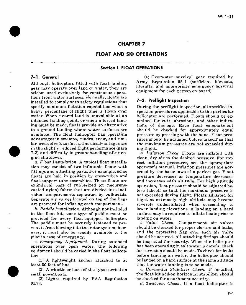
FM 1-51
CHAPTER 7
FLOAT AND SKI OPERATIONS
Section I. FLOAT OPERATIONS
7-1. General
Although helicopters fitted with float landing gear may operate over land or water, they are seldom used exclusively for continuous opera- tions from water surfaces. Normally, floats are installed to comply with safety regulations that specify minimum flotation capabilities when a heavy percentage of flight time is flown over water. When cleared land is unavailable at an intended landing point, or when a forced land- ing must be made, floats provide an alternative to a ground landing where water surfaces are available. The float helicopter has operating advantages in swamps, tundra, snow, and simi- lar areas of soft surfaces. The disadvantages are in the slightly reduced flight performance (para 7-3) and difficulty in groundhandling after en- gine shutdown.
a. Float Installation. A typical float installa- tion may consist of two inflatable floats with fittings and attaching parts. For example, some floats are held in position by cross-tubes and float-support tube assemblies. These floats are cylindrical bags of rubberized (or neoprene- coated nylon) fabric that are divided into indi- vidual compartments separated by bulkheads. Separate air valves located on top of the bags are provided for inflating each compartment.
b. Paddle Installation. Although not included in the float kit, some type of paddle must be provided for every float-equipped helicopter. The paddle must be securely fastened to pre- vent it from blowing into the rotor system; how- ever, it must also be readily available to the pilot in case of emergency.
c. Emergency Equipment. During extended operations over open water, the following equipment should be caried in the float helicop- ter:
(1) A lightweight anchor attached to at least 50 feet of line.
(2) A whistle or horn of the type carried on small powerboats.
(3) Lights required by FAA Regulation 91.73.
(4) Overwater survival gear required by Army Regulation 95-1 (sufficient lifevests, liferafts, and appropriate emergency survival equipment for each person on board).
7—2. Preflight Inspection
During the preflight inspection, all specified in- spection procedures applicable to the particular helicopter are performed. Floats should be ex- amined for cuts, abrasions, and other indica- tions of damage. Each float compartment should be checked for approximately equal pressure by pressing with the hand. Float pres- sures should be adjusted before takeoff so that the maximum pressures are not exceeded dur- ing flight.
a. Inflation Check. Floats are inflated with clean, dry air to the desired pressure. For cor- rect inflation pressures, see the appropriate operator’s manual. Inflation pressures are gov- erned by the basic laws of a perfect gas. Float pressure decreases as temperature decreases and increases with altitude. For high altitude operation, float pressure should be adjusted be- fore takeoff so that the maximum pressure is not exceeded during flight. Floats adjusted for flight at extremely high altitude may become severely underinflated when descending to lower landing elevations. A landing on a hard surface may be required to inflate floats prior to landing on water.
b. Value Check. Compartment air valves should be checked for proper closure and leaks, and the protective flap over each air valve should be secured. All attaching fittings should be inspected for security. When the helicopter has been operating in salt water, a careful check for corrosion should be made. To check for leaks before landing on water, the helicopter should be landed on a hard surface at the same altitude that the water landing is to be made.
c. Horizontal Stabilizer Check. If installed, the float kit add-on horizontal stabilizer should be checked for attachment security.
d. Tailboom Check. If a float helicopter is
7-1
FM 1-51
moored in the water, preflight inspection may be conveniently performed by sufficiently loosening the mooring lines to permit swinging the tailboom over or alongside the dock or shore.
e. Floats Used During Cold Weather Operation. During the preflight inspection, the bottom surfaces of the floats should be checked to be sure that they are not frozen to the ground or water surface. The pilot should avoid takeoff under these conditions. If only one float breaks free during liftoff, attempted takeoff with a float frozen to the surface could result in dam- age to the float and in unusual or uncontrollable attitudes of the helicopter.
7—3. Operating Characteristics of Float Helicopters
a. Except for an additional weight penalty and the slight additional drag of the floats, flight performance of the float-equipped helicopter is almost identical to standard land- ing gear flight performance. Normal airwork can be performed satisfactorily with the float- equiped helicopter. Unless extra power is ap- plied, cruise speed is reduced approximately 5 knots by the drag of the floats. This reduces the range slightly and the additional weight de- creases the payload. Maximum forward speed (red line) is reduced approximately 10 percent. For details covering specific helicopter float in- stallations, see the appropriate operator’s man- ual.
b. The float-equipped helicopter is slightly more sensitive to pedal correction. Improper pedal control results in a roll toward the outside of a skidding turn, which is caused by the aerodynamic drag forces on the lateral surfaces of the floats. For this same reason, if tail rotor failure occurs, autorotation must be entered immediately to prevent a yawing action whch produces an uncontrollable roll unless torque is quickly reduced.
c. Running takeoffs and running landings on land surfaces are not practical with float- equipped helicopters.
7—4. Hovering and Taxiing.
a. Starting and Engaging rotors. Starting the float helicopter on a hard surface is identical to the starting procedure of the conventional helicopter. Starting on water, however, pres- ents the problem of little or no antitorque con- trol until the rotor system is accelerated to ap- proximately 50 percent of its normal operating rpm. Lack of antitorque control will tend to spin the lightly loaded helicopter during starting
and runup. Heavily loaded helicopter floats have greater draft than lightly loaded helicop- ter floats. Consequently, less torquing effect oc- curs during starting with heavy loads, thus re- ducing the turning of the helicopter. Effective directional control rpm will be achieved at a lower rpm for a heavier loaded helicopter than for a lightly loaded helicopter. To overcome spinning and to prevent drifting and turning before sufficient rpm is established, the helicop- ter should be securely tied at two points, prefer- ably the fore and aft cross tubes, and drawn snugly against the dock or shore. The lines can then be cast off and the helicopter taxied out for takeoff. When a ground guide is unavailable for casting off, it may be necessary for the pilot and crew to paddle to a clear location well away from the shoreline to assure a safe start. Wind and/or water currents may cause the helicopter to turn 360° or more and drift a considerable distance before adequate control is obtained. To compen- sate for drift, a starting position may be selected near the upwind or upcurrent portion of a small lake or large river. To assure that there is no uncontrolled drift or wander, cockpit and runup checks should be carried out when the helicop- ter is at a very slow taxi. The illusion of move- ment or nonmovement described in hovering flight (c below), also applies when the rotor is engaged and the pilot attempts to maintain a fixed position on the water.
b. Taxiing. Float helicopters should not be taxied on land. On water, the float helicopter may be moved forward, sideward, or rearward, or pivoted 360° over a spot. While taxiing, the pilot must maintain normal operating rpm (green arc) range. Sufficient collective pitch should be applied to provide responsive cyclic control to start the helicopter moving forward. Maneuvering the helicopter on water is limited only by speed. Float-equipped helicopters should be taxied with the nose in the direction of movement. Maximum taxi speed is attained when the bow wave around the nose of the floats rises slightly above the normal waterline. Beyond this speed, the bow wave flows over the front portion of the floats and this severe drag may capsize the helicopter. The heavier loaded helicopter will be restricted to a slower taxiing speed.
(1) Movement of the helicopter is easy to judge when near the bank or an object in the water but becomes more difficult with increas- ing distance from a reference point. When refer- ence points are unavailable, movement may be judged by swirls, burbles, or slicks around the
7-2
FM 1-51
floats. The pilot must be careful to avoid bottom- ing collective pitch while the helicopter is in motion to avoid momentarily sinking the floats or capsizing the helicopter.
(2) Float helicopters can be taxied in water having a slight wave action, but under such conditions the floats must be kept pointed ac- ross or slightly angled into the waves and not allowed to roll in the trough. In some cases, with application of considerable collective pitch and power, the resultant downwash will have a slight smoothing effect on wind-produced waves. This applies when either taxiing or hov- ering.
(3) A ground swell can be dangerous to the tail rotor while the helicopter is riding up and pitching over the swell. Collective pitch should be applied to minimize bobbing of the helicopter.
c. Hovering Flight. When hovering near the shore or some object in the water, helicopter movement is readily discernible by reference to the shore or the nearby object. Under certain conditions, sensations experienced while hover- ing a helicopter over open water can be decep- tive. On open water without close reference points, extensive or rapid helicopter movements may go unnoticed. This condition is aggravated over very smooth or very rough water. A light breeze causing moderate rippling of the surface is the most desirable water condition. An odd sensation, similar to vertigo, is sometimes pro- duced by the concentric outward ripples result- ing from the rotorwash, and the pilot must keep his eyes moving and avoid staring at any par- ticular spot. The inexperienced pilot may well choose to initiate a slight forward movement when taking off to or landing from a hover. This will guard against undesirable backward or sideward drift during takeoff or landing. With smooth water conditions, the usual tendency is to hover too high. This is caused by the outward-flowing ripples from the rotorwash, which gives the pilot the sensation of descend- ing. He will normally respond by applying col- lective pitch to halt this apparent movement and may eventually realize he is hovering at a 10- to 15-foot altitude. Fast hover speeds should be avoided to prevent capsizing the helicopter during emergency hovering autorotations.
7-5. Takeoff and Landing a. Takeoff. Normal takeoffs with floats can be
accomplished from the water or from a hover. If this is impossible, takeoff can be accomplished from a taxi.
(1) Water takeoff. The normal procedure is a takeoff and climbout directly from the water,
moving forward into translational lift without pausing to hover. This technique is comparable to takeoff from a confined area except that bar- riers are seldom present.
(2) Hover takeoff. Takeoff from a hover should be performed in the usual manner. The major problem is in judging altitude and rate of acceleration. The usual tendency is to acceler- ate too rapidly, causing an “airspeed-over- altitude” type takeoff. During takeoff and under certain conditions, restricted visibility is en- countered due to water spray that is produced by the rotors.
(3) Takeoff from a forward taxi. Although some translational lift is available at taxi speeds, this lift is not very effective due to tuck- ing under of the floats (para 7-46) as speed is increased. Sufficient collective pitch should be applied to keep the floats riding high or skim- ming the surface. (Maximum forward airspeed that can be attained without tucking of the nose will be determined by the load and attitude of the helicopter.) While skimming the surface, float drag increases rapidly, and the takeoff must be executed promptly since a further in- crease in speed is likely to exceed the limit of aft cyclic control.
6. Landings. (1) Landing on a hard surface. All float land-
ings on a hard surface must be at zero groundspeed. Any movement on the ground sur- face will tend to scuff the floats and can cause considerable damage. Approach is made in the normal manner, terminating at a hover. Verti- cal descent is made from the hover, placing the collective pitch smoothly to the full down posi- tion after positive ground contact is made. If hovering is critical, making an approach to the ground more desirable, the approach is con- tinued through hovering altitude in a slightly nose-high attitude. Just as the aft portion of the floats touch, sufficient collective pitch is added to halt the descent and prevent forward motion. The attitude is rotated forward until firm con- tact is established, with collective pitch then reduced to the full down position.
(2) Landing on water. (а) Water with a slight chop. When landing
on water with a slight chop, the same general technique applies to this landing as that for a hard surface in (1) above.
(б) Water with a glassy surface. If the water is smooth, especially with a glassy ap- pearance, some difficulty will be experienced in determining altitude above the surface. In such case, the approach should be continued with a
7-3
FM 1-51
slow rate of descent until contact is made, avoid- ing any attempt to approach to a hover. If the rate of descent and forward speed are slow, some disturbance of the water surface will occur as ground effect builds up. The disturbance will appear as concentric ripples moving away from the helicopter and may cause the pilot to have a sensation of moving backward or descending rapidly. A natural tendency will be to apply too much collective pitch. At this point, some for- ward and downward movement should be main- tained until water contact is made. To aid in depth perception and maintain proper perspec- tive, the pilot should aviod staring at the water near the helicopter. When making approaches to a landing on a large body of water when land areas or other fixed objects are not visible, the pilot should occasionally glance to either side of the horizon to avoid stare-fixation during his approach.
(c) Landing zvith a forward airspeed. This type of landing should be used only if insuffi- cient power is available to land at speeds of less than 5 knots. Such an occasion would be when landing with high density altitude and a heavy load, or when partial power loss during or just after takeoff makes it impossible to maintain altitude. If more than a 5-knot forward speed is required for touchdown, a slight nose high at- titude is held to allow the aft portion of the floats to plane until speed has decreased to less than 5 knots. At this point the nose should be lower and collective pitch is gradually reduced to the full down position after the helicopter has come to a complete stop.
(d) Water with a rough surface. Landing the float helicopter on water can become critical when the waves are short and choppy and ex- ceed half a meter from trough to crest. These waves will cause the helicopter to pitch rapidly and may bring the rotor blades in contact with the tail boom. When the waves are the long swell type with considerable distance from crest to crest and without sharply defined ridges, it is possible to land the float helicopter in seas as high as 3 meters. If landings are to be made on waves higher than half a meter, the following techniques apply—
1. The helicopter should not be landed directly into the waves; instead, the heading should be 30° to 45° off to one side. This will minimize the fore and aft pitching of the fusel- age, and reduce the possibility of the main rotor striking the tail boom and the tail rotor making contact with the water.
2. After a water landing with power, rotor rpm should be maintained in the normal
operating range. This will permit quick takeoff if the helicopter begins to pitch excessively, or upon the approach of an especially high wave.
3. After a power off landing has been made under high wave conditions, the desired heading should be held as long as heading con- trol exists. As the rotor rpm decreases to the point that the desired heading cannot be main- tained, the rotor should be brought to a stop as quickly as possible by maintaining the collective pitch control in the full up position.
7-6. Autorotation a. On Land. Autorotative touchdown on land
with the float-equipped helicopter requires es- sentially the same technique as a regular zero ground roll autorotation with conventional skids. Although autorotational landings on a hard surface is possible, the maneuver should be limited only to actual forced landings be- cause of the excessive wear on the floats. When conditions make autorotative touchdown a crit- ical planning factor, flight routes should be planned within reach of suitable water areas where a forced landing can be made with safety.
b. On Water. Autorotative touchdown on water with forward speed is possible, although for greater safety sufficient deceleration should be accomplished to reduce forward speed to ap- proximately 5 knots. Some difficulty with depth perception may be experienced on smooth, glassy water (para 7-5b(2)(b)). Landings should be planned near a shoreline or some object in the water. This will aid greatly in judging al- titude just prior to touchdown. Touchdown should be made with a slight nose-high attitude, allowing the rear portion of the floats to plane in. Collective pitch should be applied to stop the rate of descent and to reduce the forward speed below 5 knots. Then the remainder of the pitch can be used to cushion the helicopter into the water. Collective pitch is placed in the full down position after the helicopter is riding level in the water with slow forward speed. During deceler- ation and nose-high landing, the tail rotor must not be allowed to dip into the water.
c. Antitorque Failure. Although most an- titorque rotor type helicopters can continue to fly after certain antitorque control failures, this is not usually true of the float-equipped helicop- ter. If power is not reduced immediately after antitorque failure, the float-equipped helicopter will probably enter an uncontrollable roll, caused by the large amount of aerodynamic drag on the lateral surfaces of the floats. If an antitorque failure occurs, autorotation should
7-4
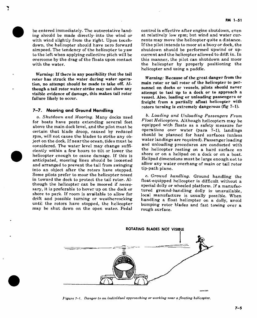
FM 1-51
be entered immediately. The autorotative land- ing should be made directly- into the wind or with wind slightly from the right. Upon touch- down, the helicopter should have zero forward airspeed. The tendency of the helicopter to yaw to the left when applying collective pitch will be overcome by the drag of the floats upon contact with the water.
Warning: If there is any possibility that the tail rotor has struck the water during water opera- tion, no attempt should be made to take off. Al- though a tail rotor water strike may not show any visible evidence of damage, this makes tail rotor failure likely to occur.
7—7. Mooring and Ground Handling a. Shutdown and Mooring. Many docks used
for boats have posts extending several feet above the main dock level, and the pilot must be certain that blade droop, caused by reduced rpm, will not cause the blades to strike any ob- ject on the dock. If near the ocean, tides must be considered. The water level may change suffi- ciently within a few hours to tilt or lower the helicopter enough to cause damage. If this is anticipated, mooring lines should be loosened and arranged to prevent the tail from swinging into an object after the rotors have stopped. Some pilots prefer to moor the helicopter nosed in toward the dock to protect the tail rotor. Al- though the helicopter can be moored if neces- sary, it is preferable to hover up on the dock or shore to park. If room is available to allow for drift and possible turning or weathercocking until the rotors have stopped, the helicopter may be shut down on the open water. Pedal
control is effective after engine shutdown, even at relatively low rpm; but wind and water cur- rents may move the helicopter quite a distance. If the pilot intends to moor at a buoy or dock, the shutdown should be performed upwind or up- current and the helicopter allowed to drift in. In this manner, the pilot can shutdown and moor the helicopter by properly positioning the helicopter and using a paddle.
Warning: Because of the great danger from the main rotor or tail rotor of the helicopter to per- sonnel on docks or vessels, pilots should never attempt to taxi up to a dock or to approach a vessel. Also, loading or unloading passengers or freight from a partially afloat helicopter with rotors turning is extremely dangerous (fig 7-1).
b. Loading and Unloading Passengers From Float Helicopters. Although helicopters may be equipped with floats as a safety measure for operations over water (para 7-1), landings should be planned for hard surfaces (unless water landings are required). Passenger loading and unloading procedures are conducted with the helicopter resting on a hard surface on shore or on a helipad on a dock or on a boat. Helipad dimensions must be large enough not to allow any water overhang of main or tail rotor tip-path plane.
c. Ground handling. Ground handling the float-equipped helicopter is difficult without a special dolly or wheeled platform. If a manufac- tured ground-handling dolly is unavailable, local manufacture is usually possible. When handling a float helicopter on a dolly, avoid bumping rotor blades and fast towing over a rough surface.
ROTATING BLADES NOT VISIBLE
ET Figure 7-1. Danger to an individual approaching or working near a floating helicopter.
7-5
FM 1-51
Section II. SKI OPERATIONS
7—8. General Army helicopters equipped with conventional gear, wheel skis, or skids, offer an effective means of mobility in the Arctic. Arctic condi- tions require special landing and takeoff proce- dures. Details on helicopter operations in Arctic areas, including minimum ice thicknesses re- quired to support Army helicopters on floating ice surfaces, are contained in FM 1-106.
7—9. Preflight Inspection of Ski Installation The pilot should—
a. Check all the steel bands and bolts secur- ing skis to skids for security and aft movement along the skids.
b. See that a rubber liner is between each steel band and the skid.
c. Inspect steel runners on the bottom of skis. d. Inspect skis on edges for separation of fiber
layers.
7—10. Landing or Takeoff in Snow Snow depth is not a limiting factor for landing or takeoff in helicopters equipped with skis. In open areas, snow may be wind compacted and blow very little in ground operations. In con- fined areas or in hilly terrain, snow may be loose and may cause severe visibility problems when landing or taking off. When landing in forma- tion in the snow, a minimum 50-meter separa- tion may be satisfactory or stagger landing at normal distances. When landing in powdered snow conditions, helicopters may have to be spaced at 50 to 100 meters apart because of blowing snow and loss of visibility near the ground.
7—11. Hovering and Taxiing on Snow and Ice To effect a reduction in blowing snow caused by rotor wash, taxiing on skis is normally favored over hovering.
Caution: Severe disorientation may result from rapid recirculation of snow down through the rotors while hovering, taxiing, or on the final ap- proach to land.
a. Hovering. When hovering over snow, the pilot should select a reference point to avoid a whiteout condition. To avoid blowing snow con- ditions when hovering forward over loose snow, he should hover at a speed just above effective translational lift speed (about 15 to 20 knots) or at a high hover.
b. Ground Taxi. Since a wheeled helicopter on
ice might skid sideways and become uncontroll- able, the pilot should taxi at slow speed (5 knots or less) and use caution on brake application. Corrective action is to lower collective pitch and place all the weight of the helicopter on the ground. If this action does not stop the helicop- ter, the only action left is to bring the helicopter to a hover. This procedure also applies to skid- equipped helicopters.
Caution: The pilot’s senses can be severely taxed by phenomena such as blowing snow drift- ing over the surface of packed snow or ice, giving him the sensation of moving (in some direction) when, in fact, he may be completely stopped or even moving in another direction. When operat- ing in such conditions, fixation can be disastrous; so the pilot must make a great, concentrated ef- fort to avoid distraction.
7-12. Troop Loading Troop loads for helicopters used in arctic opera- tions are reduced (e.g., seven troops on UH-1D/H) because of the space required for in- dividual rucksacks, survival gear, and skis or snowshoes. Additional time is required for load- ing and off-loading this equipment when land- ing zones are located in deep snow areas. Another limiting factor to be considered is the additional weight of the skis for the helicopter.
7-13. Takeoff All helicopters should use normal takeoff proce- dures in snow, stressing a proportionate in- crease of airspeed with altitude. As power is applied, instrument conditions will prevail until reaching translational lift. Pilots should be cautious on takeoff in loose, powdery snow, as a whiteout may be encountered. A standard in- strument takeoff will be safer under these con- ditions. Blowing snow problems will lessen as altitude and airspeed increase. Takeoff from ice requires no unusual techniques, except caution should be exercised when increasing or decreas- ing power to prevent any loss of directional con- trol. A slow application of power and the use of pedals will assist retention of directional con- trol. The skis may freeze to the ice under certain temperature ranges. Caution should be exer- cised on lift-off, as one ski may be free and the other frozen to the ice. Under these conditions, an alternate light application of left and right pedals will usually free the skis. Excessive ap- plication of pedals may cause structural dam- age. Skis frozen solidly to the ground should be
7-6
FM 1-51
freed by methods employed by maintenance crews.
7-14. Landing
Landing in loose snow is extremely hazardous, especially when no reference points are availa- ble.
a. When practicable, it is advisable to land near existing markers that will assist in depth perception; e.g., fences, buildings, vehicles, rocks, or trees. If suitable breaks in the snow are not available, one or more markers may be dropped (a pine branch or small tree, weighted colored cloth, or smoke grenade). An aid to depth perception is particularly important on new snow and with overcast sky conditions.
b. Because visibility will be obscured due to blowing snow caused by rotorwash, all ap- proaches should be made to the ground. This type of approach minimizes the visibility re- striction from blowing snow. Using a normal or night landing type approach with helicopters will result in improved visibility during touch- down. No unusual problems exist on landing with skis. Normal approach and landing proce- dures apply. When landing on any snow-covered surface, the approach should be planned to the ground to minimize possible whitout conditions. When the snow is not known to be hard packed, a zero speed no-hover landing should be made. When the snow is known to be very hard packed, ski-equipped helicopters may make a slightly shallow approach and running landing. The snow cloud will remain behind the cockpit until contact is made with the surface. The lower power required in the running landing also re- sults in a smaller snow cloud. Running landings and touchdown autorotations for practice should be practiced on snow or sod areas to re- duce wear on the skis. Asphalt or cement areas should be avoided when practicing running type landings. Caution should also be exercised when landing in rocky areas as cracking of the fiberg- lass will reduce the life of the skis. During the touchdown portion of a running landing or au- torotation, the heels of the skis will make con- tact first. A small amount of aft cyclic may be necessary to allow the front part of the skis to settle to the ground slowly and prevent the helicopter from bouncing to a nose-low attitude.
c. If not equipped with skis, the approach should be normal and constant in all respects, including a constant rate of deceleration (i.e., the “ideal” normal approach). As the snow cloud begins to obscure vision (15 to 30 feet above ground line), a switch is made to instruments,
with emphasis on deceleration and use of collec- tive pitch to touchdown. Under no circums- tances should a hover be attempted. The helicopter will usually land with a firm and posi- tive contact. If a previous ground reconnais- sance has not been possible, a degree of risk (commensurate with the mission) must be ac- cepted as buried rocks or stumps could cause damage to the underside of the helicopter. If time permits, a number of “dry” approaches can be made, with each approach blowing some of the loose snow away. Sometimes the only way to land under loose snow conditions is to slowly descend vertically from a high hover. If the des- cent is slow enough, the rotor wash will blow clear a suitable touchdown point and visibility should not be a problem. Many occasions will arise where loose snow conditions are such that the dangers do not warrant the risk and the proposed landing site must be relocated.
7-15. Unloading troops in deep snow
If the helicopter is to remain with the troops, they should not disembark until the rotors have stopped moving. However, if the helicopter is to take off immediately, then time and safety be- come primary considerations. A recommended procedure is for the troops to throw their equipment from the helicopter, disembark, and then lie on top of all loose equipment. (It is much safer for the troops to remain under the rotors until the helicopter has lifted off then it is to grope around for the equipment under the low ground clearance of the rotors.) Personnel within the radius of rotor wash must protect their faces by turning away from the main blast and pulling the parka hood over their heads and faces. After the helicopter departs, individuals should check each other for frostbite. Without skis, the UH-lD/H helicopter—
a. Will normally come to rest on the bottom of the fuselage with the snow about level with the helicopter floor.
b. May sink in the snow approximately 61 centimeters (2 ft), reducing the normal 236 cen- timeters (7 ft 9 in) main rotor blade clearance to approximately 152 centimeters (5 ft). Then pas- sengers depart or approach the helicopter only when cleared by the crew chief and should ap- proach from the front.
7—16. Maintenance
Current types of fiberglass skis for skid- equipped aircraft present few maintenance problems. Heavy-duty fiberglass repair kits may be used for most damaged areas of the skis. After every 100 hours of operation, after ex-
7-7
FM 1-51
tended periods of running landings or autorota- tions, or during periodic inspections, the helicopter should be jacked up and the steel runners should be inspected for wear.
7—17. Ground handling
Skis are designed with a cutaway portion for the ground handling wheels to be installed without removing the skis. Also, a cutaway portion on
the front of the skis allows for installing the tow bar.
7—18. Emergency securing in high winds
Soft snow is packed around the skis and water is poured on the snow and allowed to freeze. This, in addition to the usual tiedown procedures, will aid in preventing movement in high winds.
7-8
FM 1-51
CHAPTER 8
EXTERNAL LOAD OPERATIONS
8-1. Preflight Procedures The two basic modes of cargo are internal and external loads. Only the external load will be discussed here. Before flying an external load, an aviator must take several factors into con- sideration.
a. External Load. All external loads are di- vided into three basic categories: high density, low density, and aerodynamic. Each exhibits different characteristics in flight. The high de- nsity load offers the best stability; the low de- nsity load is the least stable. The aerodynamic load exhibits both instability and stability (in- stability inherent until load streamlining oc- curs). The aviator must determine the category, size, and weight of the load during the preflight phase of the operation.
b. Cargo Nets and Slings. Slings and cargo nets are an essential part of the external load operation and must be given the same attention during preflight inspection that the cargo re- ceives. Any evidence of frayed or cut webbing is justification for replacing the component. Be- cause of the critical strength requirements, field sewing of nylon should not be attempted, nor should nonstandard parts be substituted in assembling slings. The sling assembly must be commensurate with load requirements and must meet the requirements in the operator’s manual for the aircraft in use.
c. Operator’s Manual. Prior to sling load oper- ations, the aviator must consult the appropriate operator’s manual. Performance charts in this manual include gross weight limitations, airs- peed limitations, and endurance charts. The gross weight chart provides a rapid means of determining the load-carrying capabilities of the aircraft, within safe operating limits. The operator’s manual also gives a complete opera- tional explanation of the sling release systems. During preflight, the aviator must inspect the emergency release systems and make an opera- tional check of all normal release modes. Emergency procedures for any nonstandard oc- currence which might be experienced during ex- ternal load operations are outlined in the operator’s manual.
Caution: In extremely cold climates, structural limits can be exceeded without exceeding perfor- mance limitations.
d. Coordination With Flight and Ground Personnel. The preflight is not complete until the aviator has briefed his flightcrew and the ground crew on their duties and the mission to be performed. Essential criteria for a safe oper- ation must be fixed in each man’s thinking prior to the operation. Included in this criteria are signaling procedures in accordance with unit SOP’s, and emergency procedures covering all phases of the operation. Basic signaling may incorporate the use of radios, hand signals, col- ored smoke, and flags or panels. Any combina- tion of signals may be used in a separate exter- nal load operation.
8-2. Pickup Procedures Pickup technique varies according to the helicopter in use, type and weight of the exter- nal load, terrain involved, and wind and weather conditions at the time of pickup.
a. Approaching the Load. Normally, the ap- proach to hookup is conducted into the wind, yielding best aircraft stability. A slow forward hover allows the aviator to receive directions from the flightcrew and ground personnel with- out jeopardizing the aircraft or hookup man’s safety. When directions are received solely from ground personnel, a signalman must position himself in plain view of the aviator and give appropriate visual signals throughout the oper- ation.
b. Hover Altitude. The appropriate hover al- titude is dependent upon several variables. These variables include the type of helicopter used, terrain and ground effect, size of the load, and safety of the ground crewmen. Once an al- titude is decided, it should be kept constant to prevent false perception and possible load strikes. References should be selected in the front and to the sides of the helicopter that will assist in maintaining a constant hover altitudes and position over the load.
c. Hookup Procedure. Hookup commences with final positioning of the helicopter over the load. In cargo-type helicopters, this is normally
8-1
FM 1-51
conducted through verbal coordination with a flight crewman (crew engineer) who is in a posi- tion to closely observe the helicopter’s move- ments over the load. In helicopters that do not permit flightcrews to observe the helicopter’s movements over the load, a signalman, located on the ground and in plain view of the aviator, must be utilized. In all cases, the signals (verbal or visual) must be standardized among the per- sons involved prior to the operation (see pre- flight procedures). The load is attached to the helicopter’s cargo hook by the hookup crew when the helicopter stabilized in close proxim- ity to the load. In the event an emergency condi- tion occurs while hovering over the load and the helicopter must be landed, hookup personnel will move in the opposite direction the helicop- ter is being landed. This procedure will be estab- lished by unit SOP and all personnel will be briefed by the pilot before conducting external load operations. The hookup man will enter from the right and exit to the right. During hookup, ground personnel should never position themselves between the load and the helicopter. Attaching procedure will be in accordance with the appropriate operator’s manual, TM 55-450-8, 55-450-11, 55-450-12, 55-450-15, and 55-450-18, and unit SOP’s. The aviator in con- trol is notified immediately when the load is attached to the cargo hook. Any emergency pro- cedure following attachment, must include cargo release.
Warning: The aviator should actuate the FM radio microphone transmitter button to discharge some of the static electricity from the cargo hook before the ground crew makes the hookup.
d. Takeoff Procedure. When taking off with an external load, two distinct phases are—
(1) Lifting the load to a hover. Once the load is fixed to the helicopter, the aviator initiates a slow vertical ascent until the sling becomes taut and centered (close coordination should be maintained between the aviator, flight crew and/or ground crew to insure the aircraft does not drift from over the load). The load is then lifted to an appropriate hover altitude. At a hover, the aviator must determine whether the helicopter has available power to continue the operation. Also while at a hover, the security and proper rigging of the load is reconfirmed.
(2) Takeoff. If all criteria has been met for flight, a smooth acceleration and takeoff is in- itiated commensurate with operating limita- tions of the helicopter. Sufficient power (not to exceed maximum allowable) must be applied on
takeoff to insure that the load clears all obsta- cles by a safe altitude. Once established at a safe altitude, power should be adjusted to maintain a safe airspeed and altitude.
Note. A safe climb altitude is the altitude wherein the load is unquestionably clear of the highest barrier—usually 50 to 100 feet above the tallest immediate obstacle.
8-3. Aircraft Performance Low density, light loads generally tend to shift further aft as airspeed is increased and may become unstable. When the load is of greater density, more compact, and balanced, the ride is steadier and the airspeed may be safely in- creased. Any unstable load may jump, oscillate, or rotate, resulting in loss of control and undue stress on the helicopter. This requires reducing forward airspeed immediately, regaining con- trol, and “steadying up” the cargo load. If an external load begins oscillating fore and aft, the helicopter should be started into a shallow bank while decreasing airspeed. This will normally shift the oscillation laterally which can be easily controlled by further decreasing forward airs- peed. The weight and density of the load may determine air worthiness (steadiness in flight) and the maximum airspeed at which the helicopter may be safely flown. At the first indi- cation of a buildup in oscillation, it is mandatory to slow the airspeed immediately because the oscillation may endanger the helicopter and personnel, and may necessitate jettisoning the load. For a complete explanation of the release systems for the helicopter to be flown, see the operator’s manual.
8-4. In-Flight Procedures and Characteristics Flight characteristics and helicopter perfor- mance with external loads are dictated by vari- ous load configurations (as discussed in para 8-la).
8-5. Termination and Release Procedure Termination and subsequent load release must include—
a. Approach to Termination Point. The ap- proach to termination should not be initiated until the appropriate delivery point is iden- tified. Factors affecting the approach will not be constant. An aviator should attempt to plan an external load approach into the wind, using a normal approach angle, and terminating at a hover short of the release point in plain view of the ground crew signalman.
b. Hovering to Load Release Point. Procedure to the release point will be accomplished in the same manner as described in paragraph 8-2a
8-2
FM 1-51
and b. However, over the release point the pro- cedure reverses.
c. Releasing the Load. When the helicopter has stabilized over the load and has slack in the sling, the cargo hook is opened. Usually the cargo hook is opened through the normal re- lease modes of operation (see appropriate air- craft operator’s manual). Emergency or manual release is attempted when normal modes fail to function properly. If the cargo cannot be re- leased by the flightcrew from the helicopter, ground personnel in accordance with SOP and other directives may use any means necessary to free the load. These methods might include the use of knives, bayonets, or blade-like in- struments to cut nylon or rope components of the sling assembly. When metal components must be cut to free a load, devices such as diagonal cutters, bolt cutters, pliers, or cable cutters are appropriate.
8-6. Duties of Ground Crew a. General. The ground crew normally consists
of three men—the signalman and two hookup men. However, if the situation demands, one man may serve as the hookup crew. The trans- ported unit is responsible for providing the ground crew personnel for helicopter external load operations. These crews should be properly trained and kept abreast of developments on new equipment and operational techniques and procedures. When performing external load op- erations, they should wear goggles to prevent injury. Ground crews should be briefed by the aviation representative who is familiar with the mission to be performed. The ground crew must—
(1) Be familiar with the type of cargo to be transported.
(2) Direct the planning of the cargo load for hookup.
(3) Inspect the load to insure that the slings are not fouled and the load is secured and ready for hookup.
(4) Insure that the area to be used is clear of any obstructions.
(5) Insure that cargo weight does not exceed the capability of the helicopter, load, sling, or cargo net.
(6) Insure that the hookup area is clear of all objects that might be blown by helicopter rotor wash thus endangering ground personnel and causing damage to aircraft.
(7) Be familiar with helicopter hand signals for both day and night operations.
(8) Insure that no illumination device on the
ground may be set off by helicopter downwash during night operations.
Warning. The sling load must not be rigged a manner that could limit the helicopter’s maneuver capabilities. An improperly rigged load could cause the helicopter to be pulled into an unrecov- erable attitude by strong crosswinds or turbul- ence.
b. Duties of Signalman. (1) As the helicopter approaches the hookup
area, the signalman takes a position about 15 meters (feet) beyond and upwind from the load, facing the load with his arms raised above his head. His position must be such that the aviator can plan his approach on him; the signalman must remain in view of the aviator during the entire hookup and departure process.
(2) As the helicopter approaches the load, the signalman positions himself approximately 45° off the aviator’s side of the helicopter, re- maining approximately 15 meters (50 feet) away from the load.
(3) After the helicopter has come to a hover, the signalman guides the aviator directly over the load for hookup. (All signals must be precise, with no unnecessary movements.)
(4) After the hookup is completed, the sig- nalman signals the aviator that the load is sec- urely attached. He then gives the hookup men sufficient time to clear from beneath the helicopter before giving the aviator the signals to center over the load.
(5) As the helicopter moves upward, the signalman insures that the load is properly sec- ured and that the cargo is properly suspended.
(6) The signalman then gives the aviator the takeoff signal and moves quickly aside to be clear of the takeoff path.
c. Duties of Hookup Men. (1) As the helicopter hovers over the sling
load, the hookup men will position themselves next to the cargo to prepare for hookup. Their position should be one from which the hookup can be accomplished quickly and easily, and they will remain in plain view of the signalman at all times.
(2) After the hookup, the hookup men must insure that the cargo hook is properly secured and then move quickly from beneath the helicopter and out of the takeoff path.
Caution: Hookup personnel should be aware of the build up of static electricity on the helicopter. Before making contact with the cargo hook, they should use a grounding device to discharge the static electricity.
8-3

FM 1-51
CHAPTER 9
RESCUE HOIST OPERATIONS
Section I. INTRODUCTION
9-1. General Although the techniques and procedures for a specific rescue hoist operation will vary accord- ing to the type of helicopter and hoist system used, the same basic principles are employed for all helicopter rescue hoist operations.
9-2. UH-1 and CH-47 Series Helicopter Re- scue Hoist Systems
Detailed descriptions and operating instruc- tions for the UH-1 and CH-47 series helicopter rescue hoist systems are contained in the ap- propriate TM 55-series-10 (operator’s manual).
a. UH-1 Rescue Hoist System. The UH-1 re- scue hoist system (fig 9-1) consists of a vertical column extending from the floor structure to the cabin roof, a boom with an electrically pow- ered traction sheave, and an electrically oper- ated winch. It can be installed in any one of four alternate locations in the helicopter’s cabin. When only the pilot is at the controls, the hoist should be installed on the opposite side of the helicopter to allow the pilot to observe the ac- tions of the hoist operator. However, when both a pilot and a copilot are available, the hoist is installed behind the pilot’s (right seat) position to allow the copilot to monitor the hoist operator’s actions. Normally, the UH-1 rescue hoist is used for one survivor at a time to pre- vent an adverse effect on the helicopter center, of gravity. Figure 9-1 shows the UH-1 rescue system with the forest penetrator seat assembly (forest penetrator, para 9-3) attached.
(1) The hoist is operated by the hoist operator’s pendant control or by controls on the right-hand (pilot’s) cyclic stick.
(2) The hoist has a maximum lifting capac- ity of 600 pounds; however, the actual load may be reduced by its position in the helicopter due to weight and balance limitations. See chapter 6 of the appropriate aircraft operator’s manual.
(3) The usable cable length of the hoist is 256 feet and the entire length is color coded. The first 25 feet are color coded yellow, the next 175
feet are unpainted, the next 40 feet are yellow, and the last 16 feet are red.
(4) To cut the cable free of the helicopter in an emergency, the pilot’s cable cutter switch is mounted on the pedestal and the hoist operator’s cable cutter switch is mounted on top of the control box.
(5) The pilot’s controls override the hoist operator’s controls.
b. CH-U7 Rescue Hoist System. The CH—47 re- scue hoist system (fig 9-2) has a permanently mounted, hydraulically operated winch. A selec- tor control lever on the cable drum housing pro- vides two reeling speeds. For cargo loading, the selector control lever is moved to CARGO. For hoisting, the selector control lever is moved to RESCUE. The pilot’s winch controls are on the overhead switch panel and the hoist operator’s controls are on the winch/hoist control grip at the utility hatch. In an emergency, the hoist operator or pilot may operate an electrical cable cutter to cut the cable free of the helicopter. The cockpit switches override the winch/hoist con- trol grip switches. The hoist cable has a usable cable length of 120 feet and a maximum lifting capacity of 600 pounds.
9—3. Forest Penetrator The forest penetrator can be used to lift sur- vivors not requiring the Stokes litter (para 9-4). It is basically a rescue seat with folding prongs and safety straps (fig 9-3) that can lift up to three personnel at one time. However, because of structural limitations, the total weight can- not exceed 600 pounds.
9-4. Stokes Metal Litter This litter consists of a steel or aluminum tubu- lar frame supporting a bed of wire mesh netting and four straps to secure the survivor. It must be modified with suspension cables for use with the UH-1 rescue hoist system (fig 9^4). The Stokes litter cannot be lifted in the horizontal position through the utility hatch in the cargo compartment floor of the CH-47.
9-1
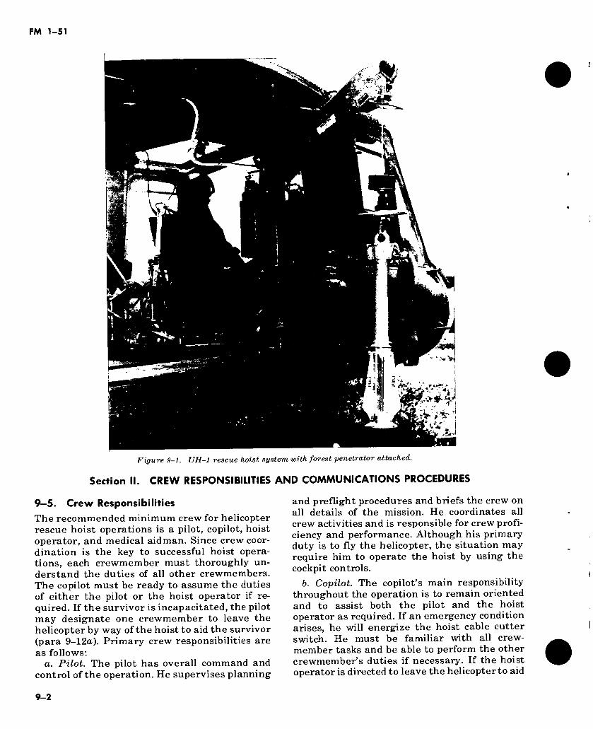
FM 1-51
â
* ‘ ,vV
r
>»■
Figure 9-1. UH-1 rescue hoist system with forest penetrator attached.
Section II. CREW RESPONSIBILITIES AND COMMUNICATIONS PROCEDURES
9—5. Crew Responsibilities
The recommended minimum crew for helicopter rescue hoist operations is a pilot, copilot, hoist operator, and medical aidman. Since crew coor- dination is the key to successful hoist opera- tions, each crewmember must thoroughly un- derstand the duties of all other crewmembers. The copilot must be ready to assume the duties of either the pilot or the hoist operator if re- quired. If the survivor is incapacitated, the pilot may designate one crewmember to leave the helicopter by way of the hoist to aid the survivor (para 9-12a). Primary crew responsibilities are as follows:
a. Pilot. The pilot has overall command and control of the operation. He supervises planning
and preflight procedures and briefs the crew on all details of the mission. He coordinates all crew activities and is responsible for crew profi- ciency and performance. Although his primary duty is to fly the helicopter, the situation may require him to operate the hoist by using the cockpit controls.
b. Copilot. The copilot’s main responsibility throughout the operation is to remain oriented and to assist both the pilot and the hoist operator as required. If an emergency condition arises, he will energize the hoist cable cutter switch. He must be familiar with all crew- member tasks and be able to perform the other crewmember’s duties if necessary. If the hoist operator is directed to leave the helicopter to aid
3
1
9-2
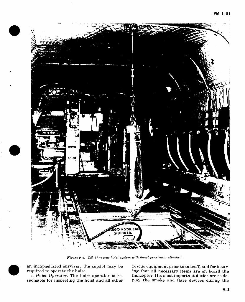
FM 1-51
yj
X
+■ i
*
£
»
ï;
t a
K V#
'-’Æ' GO HC/OK CA 20,000 IB.
<^rj. ■—«. ^
^ s . *5b- - ...a - -T 3 X % » —,
Figure 9-2. CH-47 rescue hoist system with forest penetrator attached.
an incapacitated survivor, the copilot may be required to operate the hoist.
c. Hoist Operator. The hoist operator is re- sponsible for inspecting the hoist and all other
rescue equipment prior to takeoff, and for insur- ing that all necessary items are on board the helicopter. His most important duties are to de- ploy the smoke and flare devices during the
9-3
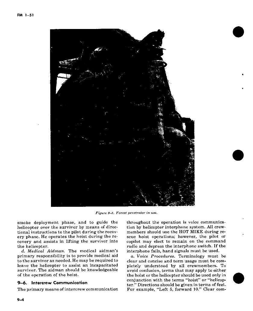
Figure 9-3. Forest penetrator in use.
smoke deployment phase, and to guide the helicopter over the survivor by means of direc- tional instructions to the pilot during the recov- ery phase. He operates the hoist during the re- covery and assists in lifting the survivor into the helicopter.
d. Medical Aidman. The medical aidman’s primary responsibility is to provide medical aid to the survivor as needed. He may be required to leave the helicopter to assist an incapacitated survivor. The aidman should be knowledgeable of the operation of the hoist.
9-6. Intercrew Communication
The primary means of intercrew communication
throughout the operation is voice communica- tion by helicopter interphone system. All crew- members should use the HOT MIKE during re- scue hoist operations; however, the pilot or copilot may elect to remain on the command radio and depress the interphone switch. If the interphone fails, hand signals must be used.
a. Voice Procedures. Terminology must be clear and concise and term usage must be com- pletely understood by all crewmembers. To avoid confusion, terms that may apply to either the hoist or the helicopter should be used only in conjunction with the terms “hoist” or “helicop- ter.” Directions should be given in terms of feet. For example, “Left 5, forward 10.” Clear com-
9-4
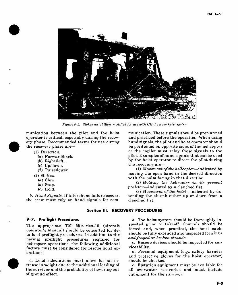
Figure 9-b. Stokes metal litter modified for use with UH-1 rescue hoist system.
munication between the pilot and the hoist operator is critical, especially during the recov- ery phase. Recommended terms for use during the recovery phase are—
(1) Direction. (а) Forward/back. (б) Right/left. (c) Up/down. (d) Raise/lower.
(2) Motion. (a) Slow. (b) Stop. (c) Hold.
b. Hand Signals. If interphone failure occurs, the crew must rely on hand signals for com-
munication. These signals should be preplanned and practiced before the operation. When using hand signals, the pilot and hoist operator should be positioned on opposite sides of the helicopter or the copilot must relay these signals to the pilot. Examples of hand signals that can be used by the hoist operator to direct the pilot during the recovery are—
(1) Movement of the helicopter—indicated by moving the open hand in the desired direction with the palm facing in that direction.
(2) Holding the helicopter in its present position—indicated by a clenched fist.
(3) Movement of the hoist—indicated by ex- tending the thumb either up or down from a clenched fist.
Section III. RECOVERY PROCEDURES
9-7. Preflight Procedures
The appropriate TM 55-series-10 (aircraft operator’s manual) should be consulted for de- tails of preflight procedures. In addition to the normal preflight procedures required for helicopter operations, the following additional factors must be considered for rescue hoist op- erations:
a. Load calculations must allow for an in- crease in weight due to the additional loading of the survivor and the probability of hovering out of ground effect.
b. The hoist system should be thoroughly in- spected prior to takeoff. Controls should be tested and, when practical, the hoist cable should be fully extended and inspected for kinks and frayed or broken strands.
c. Rescue devices should be inspected for ser- viceability.
d. Personal equipment (e.g., safety harness and protective gloves for the hoist operator) should be checked.
e. Flotation equipment must be available for all overwater recoveries and must include equipment for the survivor.
9-5
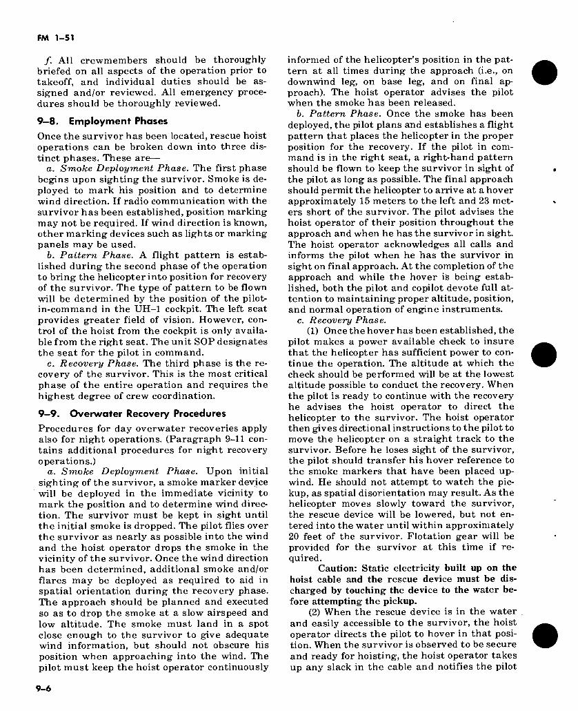
FM 1-51
/. All crewmembers should be thoroughly briefed on all aspects of the operation prior to takeoff, and individual duties should be as- signed and/or reviewed. All emergency proce- dures should be thoroughly reviewed.
9—8. Employment Phases
Once the survivor has been located, rescue hoist operations can be broken down into three dis- tinct phases. These are—
a. Smoke Deployment Phase. The first phase begins upon sighting the survivor. Smoke is de- ployed to mark his position and to determine wind direction. If radio communication with the survivor has been established, position marking may not be required. If wind direction is known, other marking devices such as lights or marking panels may be used.
b. Pattern Phase. A flight pattern is estab- lished during the second phase of the operation to bring the helicopter into position for recovery of the survivor. The type of pattern to be flown will be determined by the position of the pilot- in-command in the UH-1 cockpit. The left seat provides greater field of vision. However, con- trol of the hoist from the cockpit is only availa- ble from the right seat. The unit SOP designates the seat for the pilot in command.
c. Recovery Phase. The third phase is the re- covery of the survivor. This is the most critical phase of the entire operation and requires the highest degree of crew coordination.
9—9. Overwater Recovery Procedures
Procedures for day overwater recoveries apply also for night operations. (Paragraph 9-11 con- tains additional procedures for night recovery operations.)
a. Smoke Deployment Phase. Upon initial sighting of the survivor, a smoke marker device will be deployed in the immediate vicinity to mark the position and to determine wind direc- tion. The survivor must be kept in sight until the initial smoke is dropped. The pilot flies over the survivor as nearly as possible into the wind and the hoist operator drops the smoke in the vicinity of the survivor. Once the wind direction has been determined, additional smoke and/or flares may be deployed as required to aid in spatial orientation during the recovery phase. The approach should be planned and executed so as to drop the smoke at a slow airspeed and low altitude. The smoke must land in a spot close enough to the survivor to give adequate wind information, but should not obscure his position when approaching into the wind. The pilot must keep the hoist operator continuously
informed of the helicopter’s position in the pat- tern at all times during the approach (i.e., on downwind leg, on base leg, and on final ap- proach). The hoist operator advises the pilot when the smoke has been released.
b. Pattern Phase. Once the smoke has been deployed, the pilot plans and establishes a flight pattern that places the helicopter in the proper position for the recovery. If the pilot in com- mand is in the right seat, a right-hand pattern should be flown to keep the survivor in sight of the pilot as long as possible. The final approach should permit the helicopter to arrive at a hover approximately 15 meters to the left and 23 met- ers short of the survivor. The pilot advises the hoist operator of their position throughout the approach and when he has the survivor in sight. The hoist operator acknowledges all calls and informs the pilot when he has the survivor in sight on final approach. At the completion of the approach and while the hover is being estab- lished, both the pilot and copilot devote full at- tention to maintaining proper altitude, position, and normal operation of engine instruments.
c. Recovery Phase. (1) Once the hover has been established, the
pilot makes a power available check to insure that the helicopter has sufficient power to con- tinue the operation. The altitude at which the check should be performed will be at the lowest altitude possible to conduct the recovery. When the pilot is ready to continue with the recovery he advises the hoist operator to direct the helicopter to the survivor. The hoist operator then gives directional instructions to the pilot to move the helicopter on a straight track to the survivor. Before he loses sight of the survivor, the pilot should transfer his hover reference to the smoke markers that have been placed up- wind. He should not attempt to watch the pic- kup, as spatial disorientation may result. As the helicopter moves slowly toward the survivor, the rescue device will be lowered, but not en- tered into the water until within approximately 20 feet of the survivor. Flotation gear will be provided for the survivor at this time if re- quired.
Caution: Static electricity built up on the hoist cable and the rescue device must be dis- charged by touching the device to the water be- fore attempting the pickup.
(2) When the rescue device is in the water . and easily accessible to the survivor, the hoist operator directs the pilot to hover in that posi- tion. When the survivor is observed to be secure and ready for hoisting, the hoist operator takes up any slack in the cable and notifies the pilot
9-6
FM 1-51
that the pickup is ready to proceed. The pilot then makes a final power check to insure that sufficient power is available for the recovery. The pilot then applies sufficient power to lift the survivor clear of the water approximately 10 feet and then the hoist operator begins hoisting until the survivor is in the cabin.
Caution: The hoist operator should insure that a constant pressure is applied to the cable spool by the traction sheave on the hoist. If this device fails, the operator may be required to apply a pressure. Normally, the hook and hand- wheel provide sufficient weight to apply the re- quired 5 pounds of tension.
(3) During the pickup, using all available references and the hoist operator’s instructions, the pilot must devote full attention to maintain- ing a steady hover. The copilot monitors the instruments and remains oriented with the horizon throughout the operation to assist the pilot should the need arise. The hoist operator’s instructions to the pilot must be clear and con- cise. An example of what the pilot should hear is: SURVIVOR IN SIGHT 50 FEET AHEAD—CORRECT RIGHT-ON COURSE, SURVIVOR STRAIGHT AHEAD—ON COURSE, SURVIVOR STRAIGHT AHEAD- ON COURSE, SURVIVOR 15 FEET AHEAD— 10 FEET, SLOW—5, 4, 3, 2 FEET—OVER SURVIVOR—HOVER—LEFT 5 FEET—STOP —FORWARD 5 FEET—HOVER—HOIST GOING DOWN—HELICOPTER RISING- HOIST HALFWAY DOWN—RIGHT 3 FEET— STOP—HOIST IN WATER—HOVER—SUR- VIVOR IN HOIST—READY FOR PICKUP. The hoist operator advises the pilot when the sur- vivor is safely inside the helicopter and secured in the cabin. The pilot then transitions from a hover to forward flight into the wind.
Caution: The lateral C.G. limits may be ex- ceeded if all crewmembers are positioned on the same side of the helicopter.
9-10. Overland Recovery Procedures Procedures for overland recoveries apply for both day and night operations.
a. Smoke Deployment Phases. Procedures dis- cussed above for overwater recoveries apply. Determining wind velocity and approximate di- rection is extremely important to successful hoist operations. Smoke may be used; hovever, the wind can easily be determined by vegetation in the area. If smoke is used, it should be de- ployed in an area that is open enough to be seen from anywhere in the hoist pattern. Care should be taken to select a nonflammable target area.
b. Pattern Phase. As in overwater operations, the pattern flown should allow the pilot to main- tain visual contact with the survivor. Terrain factors and conditions encountered at the re- scue site must be evaluated to determine the best approach to be used. The pilot must keep the hoist operator informed as to the type of pattern to be flown and the position of the helicopter in the pattern at all times.
c. Recovery Phase. (1) This is the most critical phase of the op-
eration and requires the highest degree of crew coordination. The pilot must devote his full at- tention to maintaining a steady hover by using all available references and the hoist operator’s instructions. The copilot monitors the engine instruments and remains oriented with the horizon throughout the recovery to assist the pilot should the need arise. The presence of trees, wires, or other obstacles will require ex- treme caution in approaching the survivor. Since all crewmembers must aid the pilot in maintaining rotor tip clearance, all doors and/or ramps will be opened for maximum visibility. The hoist operator must give clear, concise in- structions and a continual commentary on the progress of the pickup to the pilot throughout the phase.
Caution: Static electricity build up on the hoist cable and rescue device must be discharged by touching the device to the ground before at- tempting the pickup.
(2) Prior to hoisting the survivor, the hoist operator takes up any slack in the cable and notifies the pilot that the survivor is ready to be picked up. The pilot then makes a final determi- nation that sufficient power is available to safely accomplish the recovery. He may apply sufficient power to lift the survivor clear of the ground approximately 10 feet or the hoist operator will raise the survivor while at a stationary hover. Both techniques have proven acceptable; however, the first procedure pro- vides the pilot with better control of the helicop- ter and the survivor is lifted off the ground. The hoist operator advises the pilot when the sur- vivor is safely inside the helicopter and secured in the cabin. The pilot then transitions from a hover to forward flight into the wind.
9—11. Night Recovery Procedures In addition to normal day procedures, the fol- lowing procedures are also necessary.
a. Overwater Recoveries. Due to the problem of spatial disorientation associated with night flight and night hovering over water, continu-
9-7
FM 1-51
ous flare illumination should be used whenever possible as it provides the best conditions for night recoveries. Flares improve depth percep- tion and reference to the water surface. Multi- ple smoke or marking devices deployed on the water during overwater recoveries will assist in determining wind direction and will provide a visual reference for hovering. Caution must be used to prevent smoke from restricting visibility in the immediate recovery area.
b. Overland Recoveries. As in night overwater recoveries (a above), flare illumination provides the best possible conditions for conducting night overland pickups. However, it is not absolutely necessary; helicopter lights normally provide adequate lighting to safely accomplish the re- covery.
9—12. Inert Survivor Recoveries
The procedures to be followed for the recovery of an unconscious or inert victim from water or land areas are as follows:
a. If it is determined that the survivor is un- conscious or unable to enter the rescue device, the pilot will direct one of the crewmembers to prepare to exit the helicopter and another to act as hoist operator. If the hoist operator is di- rected to leave the helicopter, the copilot moves to the cabin to operate the hoist. If a medical aidman is available, he may exit the helicopter while other crew positions remain the same.
Section IV. SAFETY AND
9—13. Conditions at Rescue Site
Because of the inherent risk, helicopter rescue hoist operations should only be conducted in those situations that preclude safe landing of the helicopter. Before attempting a recovery, the safety of the helicopter crew must be consi- dered. The pilot must evaluate the conditions at the rescue site (i.e., presence of obstacles such as trees, wires, etc.) and determine whether or not the recovery can be attempted.
9—14. Hoist Safety Factors
The following factors are important to hoist op- eration safety:
a. Free Cable. The hoist operator must be constantly alert to insure that the cable does not become entangled on immovable objects on the ground or in the water. The entire length of the cable should be kept in view at all times. If the cable does become tangled, an attempt should be made to free it by playing out slack
b. The crewmember performing the duties of hoist operator will don the hoist operator’s safety harness and assure that the crewmember preparing to leave the helicopter is secured in the rescue device. Flotation gear must be worn during all overwater recoveries and, if neces- sary, must be provided for the survivor. The pilot is notified when preparations are com- pleted in the cabin.
c. Once the crewmember is ready to exit the helicopter, he is lowered to the surface where he leaves the rescue device and secures the sur- vivor for hoisting. The hoist operator then notifies the pilot that the hoist operation is ready. The pilot will then determine if adequate power is available to accomplish the recovery.
d. The pilot applies sufficient power to lift the survivor off the ground approximately 10 feet or the hoist operator will raise the survivor while at a stationary hover. The crewmember acting as hoist operator then hoists the survivor, re- moves him from the rescue device into the cabin, and retrieves the crewmember from the surface. The crewmember operating the hoist must keep the pilot informed of the progress of the recovery. When all personnel are safely in the cabin, the pilot is notified. The pilot then transitions from a hover to forward flight into the wind. If the copilot has served as hoist operator, he then moves to his position in the cockpit or remains in the cabin to render assis- tance as necessary.
EMERGENCY PROCEDURES
and manipulating the cable. Extreme care should be used when applying tension to the cable. If the cable should break, whiplash action can cause damage to the helicopter. As a last resort, the pilot may direct that the cable be cut free of the heilcopter.
b. Avoid Pendulum Action. Extreme care should be used when hoisting the survivor. If pendulum action and rotation of the survivor are not stopped immediately, the movement may increase to unmanageable proportions. Pendulum action may be dampened by moving the cable in the opposite direction of the survivor’s movement. Rotation can be stopped by rotating the cable in a 1- or 2-foot circle in the opposite direction of the rotation of the sur- vivor.
c. Bringing Survivor Into Cabin. The best way to bring the survivor into the UH-1 cabin is to turn his back to the helicopter and then pull him in. This reduces the possibility of a
9-8
FM 1-51
semiconscious or injured survivor fighting the hoist operator. The hoist operator should not detach the rescue device from the survivor or from the hoist cable until the survivor is safely inside the helicopter and clear of the door or hatch. When conducting rescue hoist opera- tions, the hoist operator and aidman should wear safety harness.
d. Protective Gloves. Heavy protective gloves should be worn by the hoist operator to prevent injury to his hands while manipulating the cable.
e. Safety Harness Secured. Before the helicopter door/hatch is opened, the hoist operator should insure that safety harnesses are secured.
9—15. Emergency Procedures All crewmembers are required to know the fol- lowing helicopter emergency procedures:
a. Partial Loss of Power. If a partial loss of power occurs while hoisting and altitude cannot be maintained, the survivor should immediately be lowered to the surface to lighten the helicop- ter. If the situation deteriorates to the point where further action is required to prevent settling to the surface, the following action must be taken:
(1) If hoisting over land, the survivor should first be lowered to the ground and freed from the hoist. It may be necessary to cut the cable as soon as the survivor is safely on the ground. An immediate attempt should be made to recover altitude by lowering the collective pitch lever and/or attaining forward airspeed. Should an inadvertant landing occur, primary considera- tion should be given to moving away from per- sonnel on the ground. The preflight briefing should cover a preplanned direction of move- ment of the helicopter and of any crewmembers that may be on the ground. All personnel on the ground not necessary to the rescue operation must maintain a safe distance from the recov- ery sites.
(2) If hoisting over water, the survivor should be lowered into the water and the cable cut to avoid dragging him in the water. An im- mediate attempt to recover altitude should be made. Should an inadvertent landing occur,
primary consideration should be given to mov- ing away from personnel in the water. The pre- planned direction of movement in (1) above ap- plies here also.
b. Complete Loss of Power. If a complete loss of power occurs, the procedures that should be followed are—
(1) Pilot—Alert crew and perform emergency autorotation (para 4-9). If possible, the pilot should maneuver the helicopter away from the survivor.
(2) Hoist operator—Prepare for emergency landing.
c. Hoist Failure. (1) A recovery may be continued if the hoist
mechanism fails to raise or lower from the cable extended position. The survivor should be ad- vised of the problem by hand and arm signals and instructed to remain firmly attached to the recovery device. Before entry into forward flight, the helicopter should ascend to an al- titude that insures the survivor is clear of all obstacles. With the survivor suspended from the helicopter, recovery may proceed to an area where a safe landing can be made. Flight to the landing area is made at a much slower speed than normal.
Warning: As pendular action and rotation may become uncontrollable if airspeed becomes too high, extreme care must be used when at- tempting forward flight with the hoist cable ex- tended with a survivor attached.
(2) During landing with the survivor sus- pended from the helicopter, extreme care must be exercised to prevent dragging the survivor and entangling the cable in the tail rotor sys- tem. The hoist operator and/or pilot must main- tain light tension on the cable during landing. After the survivor has been gently lowered to the ground from a vertical descent.
(а) The emergency cable cutter may be actuated to free the cable from the helicopter to permit landing, or
(б) The helicopter may be hovered to the side of the survivor and landed with the cable still attached. Then the cable may be detached from the survivor and stored inside the helicop- ter.
9-9

FM 1-51
CHAPTER 10
FORMATION FLYING
Section I. INTRODUCTION
10-1. Terminology
The following terminology is used throughout the armed services and our allied NATO na- tions.
a. Section/Element. A two or three helicopter formation. The two helicopter section/element is the basic building block for all larger forma- tions.
b. F light I Division. Four or more helicopters in two or more sections/elements.
c. Company ¡Squadron Formation. A forma- tion of two or more separate flights/divisions. The number of helicopters is determined by the size of the company/squadron.
d. BattalionfWing Formation. A formation of two or more companies/squadrons.
Note. See paragraph 10-8 for the numbering of aircraft in formation.
10-2. Definition
a. U5° Bearing. A relative bearing between the nose of the helicopter and the pilot’s line of sight, right or left, depending upon the direction of the rendezvous and joinup.
b. Column Formation. A formation in which all of the largest integral subdivisions (each in identical formation) are positioned one directly behind the other.
c. Crossover. General. The generic term used to describe the action of an aircraft passing lat- erally from one position (in a formation) above the altitude of a specified aircraft to another position in the formation.
(1) Fixed wing. In fixed wing formation fly- ing, the airplane performs the crossover by pas- sing laterally over the top or part of the top of another airplane.
(2) Rotary wing. In rotary wing formation flying, the helicopter performs the crossover by passing laterally above and to the immediate rear of another helicopter.
d. Crossunder. General. The generic term used to describe the action of an aircraft passing laterally from one position (in a formation)
below and the altitude of a specified aircraft to another position in the formation.
(1) Fixed wing. In fixed wing formation fly- ing the airplane performs the crossunder by passing laterally beneath the underside or part of the underside of another airplane.
(2) Rotary wing. The crossunder is not per- formed with helicopters in formation because of the inherent danger involved.
e. Echelon Formation. An arrangement of aircraft in flying formation in which each air- craft or each flight of aircraft flies at the same level or at a level above or below another air- craft or flight in the formation, and usually at a distance to the right or left. /. Formation (Flying). A formation consists
of two or more aircraft, holding positions rela- tive to each other, and under the command of a designated aviator therein.
g. Free Cruise. Free cruise is the technique whereby the wingman maintains a specified dis- tance from the leader but may vary the bearing from the leader during turns. This distance is measured perpendicular to the lateral line that passes through the tail region of the leader to the lateral line that passes through the nose region of the wingman. The wingman, as he maintains this distance, is free to maneuver during turns (or if otherwise required) in the airspace extending from 45° on either side of the leader’s tail. In other words, it is said that the aviator owns the airspace extending from 45° on either side of the leader’s tail and is free to maneuver through this airspace during turns. This technique applies to flight, company, or larger formations.
h. Hand Signals. A visual signal or communi- cation made by using the hands and arms. By using the appropriate hand signal, a flight leader can signal the wingman to move from one position to another.
i. Horizontal Distance and Vertical Separa- tion of Aircraft.
(1) Horizontal distance. (a) Close formation. In a close formation,
10-1
FM 1-51
the horizontal distance between helicopters is normally IVz rotor-disc diameters measured be- tween tip-path planes.
(b) Loose formation. In a loose formation, the horizontal distance between helicopters is 3 to 6 rotor-disc diameters.
(c) Extended formation. In an extended formation, the horizontal distance between helicopters may be any required distance in ex- cess of six rotor diameters, dependent upon the tactical requirements.
(2) Vertical separation. (а) Flat (separation). All helicopters or all
flights of helicopters are flown at the same al- titude.
(б) Stepped-up (separation). The vertical separation between the wingman and the section/element leader is measured from the al- titude of the leader upward to the altitude of the wingman. Example: The wingman was flying a 3-foot stepped-up position on the leader.
(c) Stepped-down (separation). The verti- cal separation between the wingman and the section/element leader is measured from the al- titude of the leader downward to the altitude of the wingman. Example: The wingman was fly- ing a 3-foot stepped-down position on the leader.
Note. The stepped-down formation is never used for helicopter formation flying because wingmen are likely to experience difficulty in distinguishing the flicker of their own rotor blades from that of the leader, thereby, increasing the probability of an accident.
Section II. PRINCIPLES
10-3. Introduction
a. Formation flying is the maneuvering of aircraft (into a flight pattern) in accordance with established tactics, techniques, and proce- dures, upon the command of a designated leader. It includes the rapid but controlled change from a specific formation suitable for one set of conditions to another formation de- signed to meet the requirements of an entirely different set of conditions.
b. Aerodynamic interference between inflight helicopters must be anticipated. When two helicopters operate in close proximity, as in trail formation, the interacting patterns of airflow alter the aerodynamics of each helicopter. The leading helicopter may experience an increase in downwash at the tail and a noseup change in pitching movement. The trailing helicopter will experience a reduction in downwash at the tail, and a nosedown change in pitching movement. Thus, a definite possibility of collision exists be-
j. Join Up. To form separate airplanes or helicopters into a specific flight formation.
k. Lead; Lead Helicopter. The helicopter at the head of a helicopter formation. Also the av- iator who flies in the lead helicopter.
l. Nose to Tail Distance. The distance from the tail region of a specified formation leader to the nose region of a particular wingman; or, in multiple formations, the distance from the tail region of one formation to the nose region of another formation.
m. Rendezvous. A prearranged meeting at a given time and place from which to begin an action or phase of operation, or to which to re- turn after an operation; e.g., to assemble, meet, or arrive at a rendezvous; to meet with another or others in rendezvous.
n. Rendezvous and Join Up. To assemble and form into a specific flight formation.
o. Staggered Trail (Left or Right). A forma- tion in which all aircraft are alternately stag- gered behind the leader.
p. Trail. A formation in which all aircraft are in single file, each directly behind the other. The aircraft may be flown at the stepped-up position or at the same level.
q. Wingman. An aviator who flies at the side and to the rear of or directly behind a section/element leader, commonly in a 2-helicopter or 3-helicopter formation; also, the helicopter flown in this position.
OF FORMATION FLYING
cause of the trim change experienced by each helicopter. In formation flying, the aviator must anticipate this type of interference, particularly when flying in the trail position or when execut- ing a crossover from one position in the forma- tion to another. Care must be taken to antici- pate the trim change and to maintain adequate clearance.
c. Careful planning before conducting forma- tion flights is essential to the safe, efficient con- trol and maneuver of any size formation. Safe and orderly formation flight is the result of ex- tensive training, continuous practice, and a high degree of air discipline. Personnel undergo- ing this type training must do so with an ex- treme sense of responsibility and with constant vigilance. Although formation flying is not in- herently dangerous, any aspect of this training can be disastrous if principles are violated.
d. The tactics, techniques, and procedures set forth in this chapter apply to the requirements
10-2
FM 1-51
of armed and unarmed helicopter formations. e. The distance between helicopters or forma-
tions of helicopters can be greatly increased to fit the tactical situation. At higher altitude, for example, a flight of four helicopters should be positioned 50 to 100 meters or farther apart, so that a burst of antiaircraft fire would not de- stroy the entire flight.
10-4. Formation Considerations
Factors to be considered in determining the best formation to be used in a specific situation include—
a. Mission Requirements. (1) Mission of the supported unit. (2) Mission of the helicopter unit.
b. Enemy Considerations. (1) Current enemy situation. (2) Enemy antiaircraft and air defense
capability. (3) Accessibility to enemy visual and/or
electronic surveillance. c. Fire Support Plan.
(1) Artillery support available. (2) LZ preparation planned. (3) Air support availability and
requirements— (a) Type aircraft. (b) Type ordnance. (c) Naval gunfire (if available).
d. Ordnance. Type ordnance to be used for neutralization fire.
e. Terrain and Weather. (1) Configuration of en route obstacles
and/or corridors. (2) Size, shape, and surface of the LZ. (3) Obstacles in or affecting approaches to
LZ. (4) Ceiling and visibility. (5) Winds and turbulence.
/. Formation Manuever and Flexibility. (1) Possible changes in mission or situation. (2) Evasive tactics.
g. Armed Aerial Escort. (1) Amount of armed escort required. (2) Number and type of armed escort
helicopters available. (3) Position in the formation. (4) Mission of the armed helicopters.
h. Control of Formation. (1) Degree of control required. (2) Method of control (radio, hand signals,
prearranged timing, etc.). i. Other Considerations.
(1) Type aircraft. (2) Crew training and experience.
10-5. Rendezvous and Joinup Principles
To understand the rendezvous and joinup, the term 45° bearing as defined in paragraph 10-2a must be clearly understood. There are three dis- tinct types of rendezvous and joinup: the running, the circular, and the 180° reversal.
a. The Running Rendezvous and Joinup. A running rendezvous and joinup is a means of assembling a number of helicopters into a for- mation while proceeding on course. It may occur during an on-course climb or while the helicop- ters are at a constant altitude. Helicopters ex- ecuting a running rendezvous and joinup should join in position rather than in echelon, as follows:
(1) If fuel consumption and /or time presents no problem, the leader may elect to proceed di- rectly on-course with the remainder of the flight joining by using higher power settings. This can be accomplished by the lead aircraft maintain- ing 20 knots less than the en route airspeed until the flight has joined. If fuel consumption and/or time has to be considered, the leader should S-turn about the base course until all members of the formation have joined. By using a 20° to 30° angle of bank, the leader will turn until the heading is 60° off the track to be made good and then reverse to a 60° deviation in the opposite direction. These turns should be con- tinued until all members of the flight have joined.
(2) The members of the flight joining will continue on base course until the leader is on a 45° bearing to their opposite side. When the leader reverses the turn, all helicopters that have commenced their joinup will reverse course, cut to the inside of the turn, and place the leader on a 45° bearing. This procedure is continued until each helicopter has joined the formation. By employing the S-turn, all mem- bers of the formation use approximately the same power settings.
b. The Circular Rendezvous and Joinup. The circular rendezvous and joinup is used to over- come conditions which prevent pilots from keep- ing the helicopter ahead in sight after takeoff (instrument climbout, etc.).
(1) The leader will take off, climb on top, and, upon reaching the orbit point, establish an orbit using 20° to 30° bank.
(2) The position of the leader in his orbit will determine the procedures used by the rest of the flight as each pilot approaches prosition for joinup. This position on the circle will be in terms of a position on the face of a clock relative to the center of the orbit. The point at which the
10-3
FM 1-51
joining helicopter crosses the circle will always be the 6 o’clock position. When the joining helicopter reaches the outside of the rendezvous circle and the leader is in a left-hand turn orbit between the 2 and 6 o’clock position or in a right-hand orbit between the 10 and 6 o’clock position, the joining helicopter turns toward the leader. This turn is held until the leader is on a 45° bearing and the joining pilot’s line of sight is on the leader. The joining pilot then maintains the same relative bearing on the leader until joinup is effected.
(3) If the leader is in a position on the circle other than that described in (2) above, the join- ing helicopter will continue to the center of the circle. When at the center, if the leader is bet- ween the 10 and 2 o’clock position, the joining helicopter will turn toward the leader until the nose of his helicopter is pointed directly toward the leader’s helicopter. The joining helicopter pilot will then level his nose and his line of sight is on the leader’s helicopter. The joining helicopter pilot will then level his helicopter and fly straight and level until the leader is on a 45° bearing to either side of his nose. He will then roll his helicopter into a 45° bank and hold it until the leader is on a 45° bearing to the oppo- site side of his nose and his line of sight is on the leader’s helicopter. If the leader is in a position other than between 10 and 2 o’clock when the joining helicopter reaches the center of the re- ndezvous circle, the joining helicopter will roll into a 45° bank and hold until the leader is on a 45° bearing and his line of sight is on the leader’s helicopter.
c. The 180° Reversal Rendezvous and Joinup. This is the most difficult type of rendezvous and joinup to perform and requires skill and team- work from all members of the formation.
(1) To perform the 180° reversal method of rendezvous and joinup, all helicopters will be in trail formation behind the leader.
(2) After allowing enough time for every air- craft to get into position behind the leader, the leader will commence a 180° standard rate turn in the desired direction.
(3) After the leader has moved, approxi- mately 45° to the left or right, the second helicopter should commence the rendezvous turn. Normally, by turning early, the second
SECTION III. TYP
10-6. Free Cruise
a. When aviators are required to fly a fixed
helicopter will be able to join up before the leader has completed his 180° turn. Each suceed- ing pilot should commence his turn, in order, as the leader approaches a 45° bearing to the left or right. This turn should be relatively steep but should be adjusted to position the joining helicopter slightly ahead of the leader and on a closing angle to the rendezvous heading of ap- proximately 45°. As the distance narrows, the closing angle to rendezvous heading should be reduced to ease the relative motion. All relative motion should be stopped before the rendezv- ousing helicopter makes the final joinup into position.
(4) At times the 180° rendezvous turn will not be executed exactly as desired. If the turn is made too early, the joining helicopter will find that he is well ahead of the leader; conversely, a late turn will place the joining helicopter to the rear of the leader. The rendezvous and joinup can be salvaged, however, if the relative bearing to the leader is within 5° to 10° of the desired bearing of 45°.
(5) The individual aviator should, upon com- pletion of the 180° rendezvous turn, make an immediate estimate of both his closing angle to the rendezvous heading and the bearing to the leader’s helicopter. If the relative bearing to the leader is shallow, an immediate increase in speed will save the rendezvous. If the relative bearing to the leader is excessive, a slight re- duction in power will save the rendezvous.
(6) The aviator of the joining helicopter should pay careful attention to his closing angle on the rendezvous heading. If the joining helicopter is on the correct relative bearing to the leader but his closing angle to the rendezv- ous is very shallow (less than 30° to the rendezv- ous heading), he should immediately increase speed. Conversely, if the joining helicopter is in the correct relative bearing to the leader but his closing angle is steep (greater than 50° to the rendezvous heading), he should reduce speed slightly and continue his turn toward the re- ndezvous heading.
Note. The helicopter ahead must be kept in sight at all times. Therefore, if the helicopter ahead falls behind in mak- ing a rendezvous, succeeding aviators must adjust their turn to keep him in sight even at the expense of also falling behind. If the helicopter ahead falls only slightly behind, the following helicopter can usually continue a normal rendezv- ous turn and wait momentarily on the inside of the turn until the helicopter ahead effects a joinup.
OF FORMATIONS
position in a formation that cannot be freely varied in turns, excessive power changes are
10-4
FM 1-51
necessary to maintain position. Such power changes increase fuel consumption, pilot fatigue, etc. For example, in a 3- or 5-helicopter V-formation, the position of the wingman re- mains fixed, even in steep right or left turns. The only way a wingman can maintain his rigidly defined position is to increase power if he is on the outside of a turn, and to decrease power if he is on the inside of a turn.
b. In a 2-helicopter element, the position of the wingman is not as rigid as in a 3-helicopter element fixed position V formation. The wing- man has the prerogative in a steep turn to move freely from a position 45° to the right rear on the other side. Such a prerogative is called free cruise (para 10-2<7). It allows the wingman to maintain position with an established power setting by matching his relative speed with that of the leader.
(1) The wingman’s relative speed is less than that of the element leader when the wing- man is on the outside of a turn. Thus, he must use a slightly faster rate of turn and move momentarily toward the 45° position on the in- side of the turn until a point is reached where his relative speed matches that of the leader.
(2) The wingman’s relative speed is greater than that of the element leader when the wing- man is on the inside of a turn. Thus, he must use a slightly slower rate of turn and move momen- tarily toward the 45° position on the outside of the turn until a point is reached where his rela- tive speed matches that of the leader.
c. Ina 4-helicopter flight formation, when the second element is in heavy right or heavy left position, the same procedures (ft above) apply. The second element may slide toward the out- side of the turn when its relative speed is grea- ter than that of the flight leader, and toward the inside of the turn when the relative speed is less than that of the flight leader.
d. The same procedure (c above) can be used when two or more flights are in formation. Thus, large numbers of helicopters can be flown in formation without sacrificing maneuverability.
10-7. Sequential Numbering of Aircraft in a Formation
To provide for the Army’s future requirements and present operational necessities, it is impor- tant that a consistent system of numbering air- craft in any type of flying formation be estab- lished. Aircraft formations are usually illus- trated and described as seen from above (plan view). The basic or key formation (from which other related formations may be formed) is used
to determine the numbering sequence. The two basic or key formations are the two-helicopter element (flexible position with the prerogative of free cruise) and the three-helicopter element (fixed position) V-formation that does not pro- vide for free cruise.
a. Flexible Position Formations. Flexible pos- ition formations that employ the principle of free cruise include but are not limited to the following:
(1) The two-helicopter section ¡element. The arrow in figure 10-1 indicates the lateral space area a helicopter may occupy in a free cruise (para 10-6) 2-helicopter section/element.
(2) The three-helicopter section/element. The V-formation is a heavy left or heavy right (fig 10-2) 3-helicopter section/element (free cruise).
(3) The four-helicopter flight/division. This formation is for tactical flight and may be flown heavy left or heavy right (fig 10-3).
(4) The five-helicopter flight/division. This tactical flight formation may be flown heavy left or heavy right (fig 10^4).
(5) The six-helicopter flight/division (4/2). This tactical flight formation may be flown heavy left or heavy right (fig 10-5). It is com- posed of one 4-helicopter flight/division and one 2-helicopter section/element.
(6) The six-helicopter flight/division (3/3). This tactical flight formation may be flown heavy left or heavy right (fig 10-6). It is com- posed of two 3-helicopter sections/elements (free cruise).
b. Numerical Sequence of Free Cruise Formations. Helicopters within free cruise for- mations are numbered, starting with the leader as No. 1; then, progressively, left to right later- ally through each succeeding lateral space area (in the same manner as words and lines on a written page). These formations can be changed easily into other related formations such as a column or trail, right echelon, and left echelon, and still maintain their original numerical se- quence within the new formation without one or more helicopters being repositioned into a new lateral space area.
c. Fixed Position Formations. Formations that require the wingman to remain in a fixed position in turns rather than employ free cruise include but are not limited to the following:
(1) The three-helicopter section/element, fixed position. The fixed-position three- helicopter element is shown in figure 10-7.
(2) The five-helicopter flight/division, fixed position. This flight formation is shown in figure 10-8.
10-5
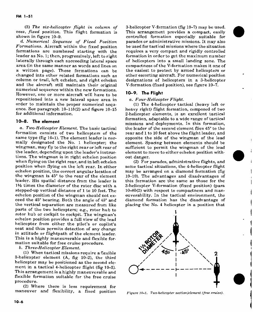
FM 1-51
(3) The six-helicopter flight in column of vees, fixed position. This flight formation is shown in figure 10-9.
d. Numerical Sequence of Fixed Position Formations. Aircraft within the fixed position formations are numbered starting with the leader as No. 1; then, progressively, left to right laterally through each succeeding lateral space area (in the same manner as words and lines on a written page). These formations can be changed into other related formations such as column or trail, left echelon, and right echelon and the aircraft still maintain their original numerical sequence within the new formations. However, one or more aircraft will have to be repositioned into a new lateral space area in order to maintain the proper numerical sequ- ence. See paragraph 10-116(2) and figure 10-15 for additional information.
10-8. The element a. Two-Helicopter Element. The basic tactical
formation consists of two helicopters of the same type (fig 10-1). The element leader is nor- mally designated the No. 1 helicopter; the wingman, may fly to the right rear or left rear of the leader, depending upon the leader’s instruc- tions. The wingman is in right echelon position when flying on the right rear, and in left echelon position when flying on the left rear. In either echelon position, the correct angular location of the wingman is 45° to the rear of the element leader. His spatial distance from the leader is IV2. times the diameter of the rotor disc with a stepped-up vertical distance of 1 to 10 feet. The echelon position of the wingman should not ex- ceed the 45° bearing. Both the angle of 45° and the vertical separation are measured from like parts of the two helicopters; e.g., rotor hub to rotor hub or cockpit to cockpit. The wingman’s echelon position provides a full view of the lead helicopter from either the pilot’s or copilot’s seat and thus permits detection of any change in attitude or flightpath of the element leader. This is a highly maneuverable and flexible for- mation suitable for free cruise procedure.
b. Three-Helicopter Element. (1) When tactical missions require a flexible
3-helicopter element (A, fig 10-2), the third helicopter may be positioned as the second ele- ment in a tactical 4-helicopter flight (fig 10-3). This arrangement is a highly maneuverable and flexible formation suitable for the free cruise procedure.
(2) Where there is less requirement for maneuver and flexibility, a fixed position
3-helicopter V-formation (fig 10-7) may be used. This arrangement provides a compact, easily controlled formation especially suitable for parades or administrative missions. It may also be used for tactical missions where the situation requires a very compact and rigidly controlled formation in order to get the maximum number of helicopters into a small landing zone. The compactness of the V-formation makes it one of the easiest to protect by armed helicopters or other escorting aircraft. For numerical position designations of helicopters in a 3-helicopter V-formation (fixed position), see figure 10-7.
10-9. The Flight a. Four-Helicopter Flight.
(1) The 4-helicopter tactical (heavy left or heavy right) flight formation, composed of two 2- helicopter elements, is an excellent tactical formation, adaptable to a wide range of tactical missions and deployments. In this formation, the leader of the second element flies 45° to the rear and 1 to 10 feet above the flight leader, and opposite the side of the wingman of the lead element. Spacing between elements should be sufficient to permit the wingman of the lead element to move to either echelon position with- out danger.
(2) For parades, administrative flights, and some tactical situations, the 4-helicopter flight may be arranged on a diamond formation (fig 10-10). The advantages and disadvantages of this formation are the same as those for the 3- helicopter V-formation (fixed position) (para 10-86(2) with respect to compactness and man- euverability. In the tactical environment, the diamond formation has the disadvantage of placing the No. 4 helicopter in a position that
/ 'W \
Ó&V ± N V' /
<8r O' y : -TAS \ 2
1-
Figure 10-1. Two-helicopter section/element (free cruise).
10-6
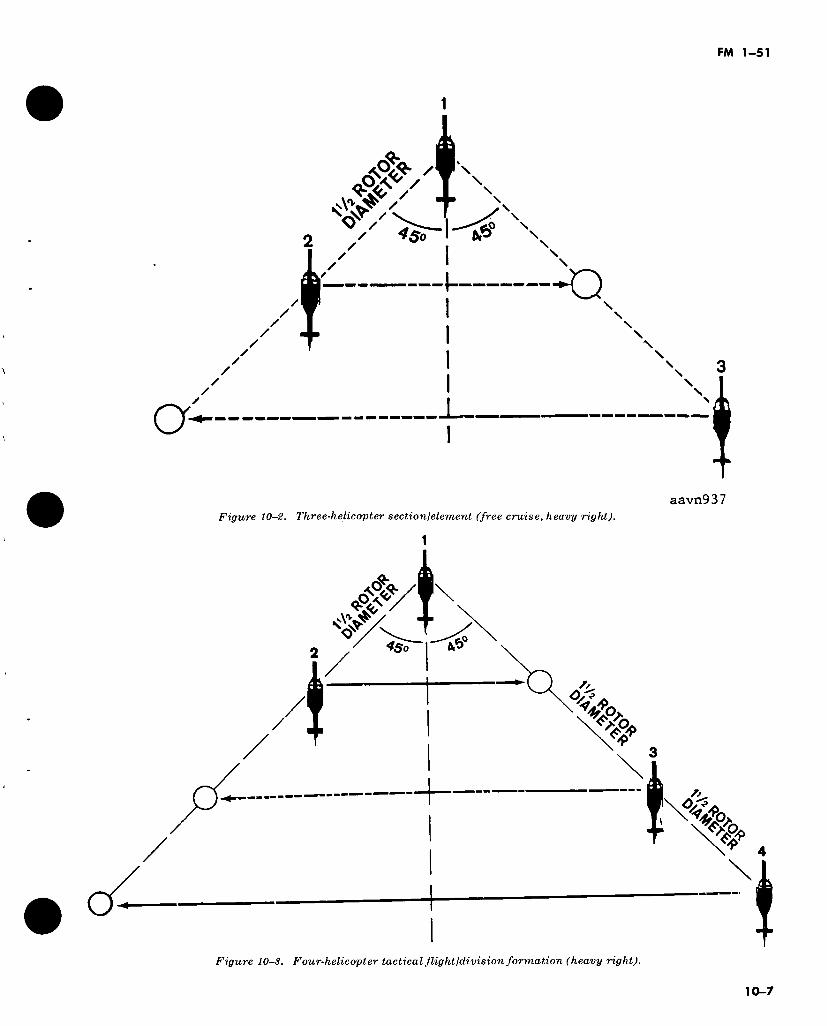
FM 1-51
*#VT\ \
T X
/
/
► / I __—^0 s / 4$0 I tP NN
/ 1.
N \
✓
/ /
N
\ ? \
N
aavn937 Figure 10-2. Three-helicopter section/element (free cruise, heavy right).
1
&
à*??
0/5 / >0U
W
%
Figure 10-3. Four-helicopter tactical flight/division formation (heavy right).
10-7
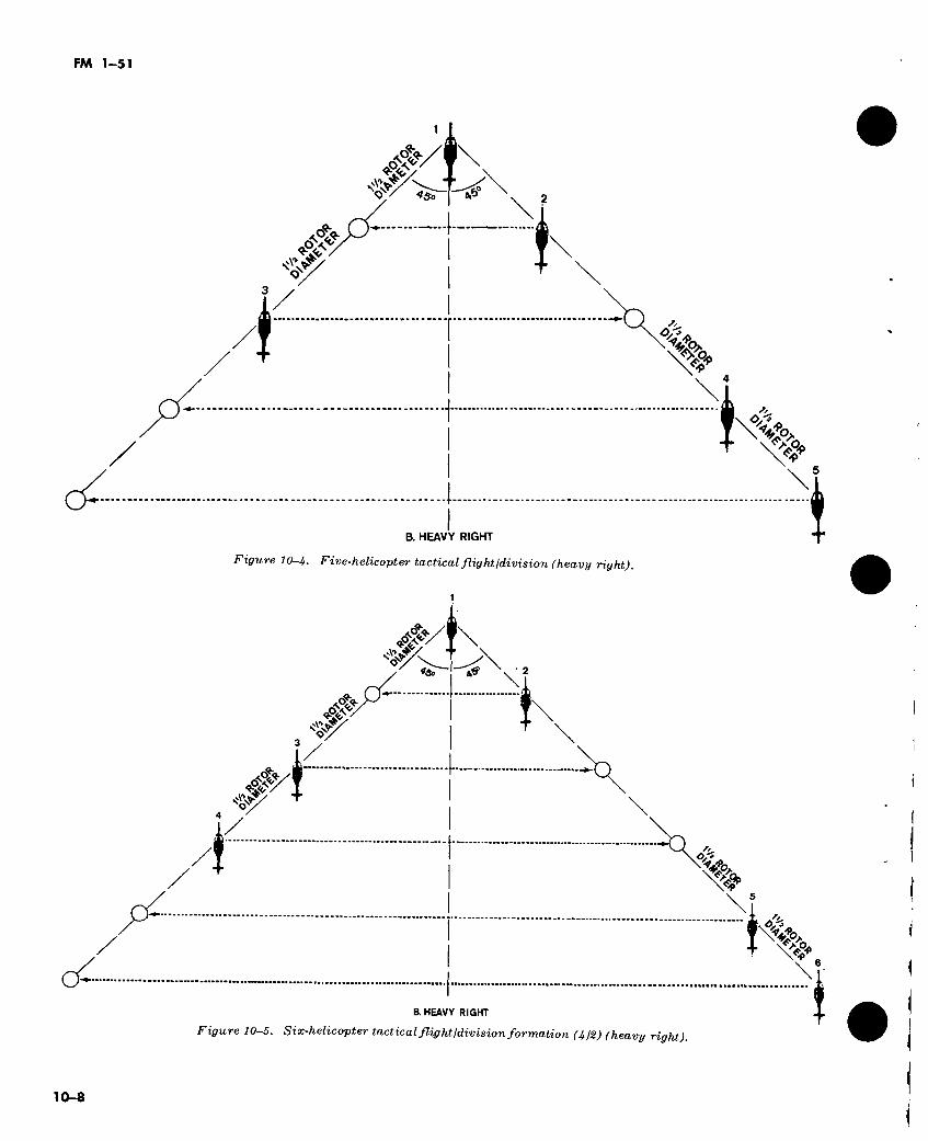
FM 1-51
<§£/ I \
PX
v
O."?
^:o
B. HEAVY RIGHT
Figure 10-4. Five-helicopter tactical flight ¡division (heavy right).
rf \ ■ 2
#>
¥
3
i 0/9
5
\6
B. HEAVY RIGHT
Figure 10-5. Six-helicopter tactical flightldivision formation (4¡2) (heavy right).
10-8
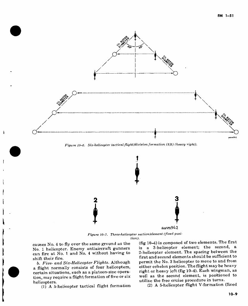
ö-
Figure 10-6. Six-helicopter tactical flight ¡division formation (3/3) (heavy right).
1
Ï \ aavn942
Figure 10-7. Three-helicopter sectionfelement (fixed posi- tion).
causes No. 4 to fly over the same ground as the No. 1 helicopter. Enemy antiaircraft gunners can fire at No. 1 and No. 4 without having to shift their fire.
b. Five- and Six-Helicopter Flights. Although a flight normally consists of four helicopters, certain situations, such as a platoon-size opera- tion, may require a flight formation of five or six helicopters.
(1) A 5-helicopter tactical flight formation
(fig 10—4) is composed of two elements. The first is a 3-helicopter element; the second, a 2-helicopter element. The spacing between the first and second elements should be sufficient to permit the No. 3 helicopter to move to and from either echelon position. The flight may be heavy right or heavy left (fig 10-4). Each wingman, as well as the second element, is positioned to utilize the free cruise procedure in turns.
(2) A 5-helicopter flight V-formation (fixed

FM 1-51
1
* í * í
Figure 10-8. Five-helicopter flight ¡division (fixed position).
\ ¡ i
4
l 5 6 i «
aavn944 Figure 10-9. Six-helicopterflightldivision in column of vees
(fixed position).
position) (fig 10-8) is compact and easy to con- trol. It is somewhat devoid of maneuverability and cannot utilize free cruise. It should not be used when the threat of enemy air attack is present or there is a likelihood of encountering sophisticated enemy antiaircraft weapons.
(3) One type of 6-helicopter tactical (flexible position) formation is a flight composed (fig 10-6) of two 3-helicopter elements in V-formation (flexible position). The second ele- ment may be in a column formation or positioned 45° to either side of the first element and can utilize free cruise.
(4) Another 6-helicopter tactical formation (fig 10-5) is composed of a 4-helicopter flight and a 2-helicopter element. The 4-helicopter flight may be in the heavy right or heavy left config- uration. (Since a 4-helicopter flight is composed of two 2-helicopter elements, the additional 2-helicopter element is numbered the third ele- ment.) The third 2-helicopter element is positioned 45° to the rear of the flight leader on the side opposite the second element (fig 10-5). Each helicopter within the formation is positioned to utilize the free cruise procedure.
(5) When forming a flight of more than five helicopters into a fixed position V-formation, the flight should be formed into a column of vees (fig 10-9) with no more than three helicopters per V-formation or element. More than three helicopters in a single V element would severely limit maneuverability of the formation. The spacing between vees should be sufficient to
10-10
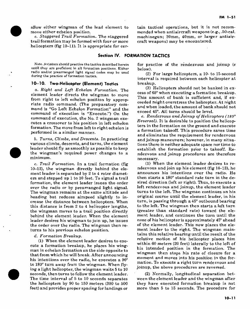
FM 1-51
allow either wingman of the lead element to move either echelon position.
c. Staggered Trail Formation. The staggered trail formation may be formed with four or more helicopters (fig 10-11). It is appropriate for cer-
tain tactical operations, but it is not recom- mended when antiaircraft weapons (e.g., .50-cal. machinegun; 20mm, 40mm, or larger antiair- craft weapons) may be encountered.
Section IV. FORMATION TACTICS
Note. Aviators should practice the tactics described herein until they are proficient in all formation positions. Either radio and/or prearranged light signal codes may be used during the practice of formation tactics.
10-10. Two-Helicopter (Element) Tactics
a. Right and Left Echelon Formation. The element leader directs the wingman to move from right to left echelon position by approp- riate radio command. (The preparatory com- mand is “Go Left Echelon Formation” and the command of execution is “Execute.”) On the command of execution, the No. 2 wingman exe- cutes a crossover to his position in left echelon formation. The move from left to right echelon is performed in a similar manner.
b. Turns, Climbs, and Descents. In practicing various climbs, descents, and turns, the element leader should fly as smoothly as possible to keep the wingman’s required power changes to a minimum.
c. Trail Formation. In a trail formation (fig 10-12), the wingman directly behind the ele- ment leader is separated by 2 to 4 rotor diamet- ers and stepped up 1 to 10 feet. To signal a trail formation, the element leader issues the order over the radio or by prearranged light signal. The wingman remains at the same altitude and heading but reduces airspeed slightly to in- crease the distance between helicopters. When this distance is from 2 to 4 helicopter lengths, the wingman moves to a trail position directly behind the element leader. When the element leader desires his wingman to join up, he issues the order over the radio. The wingman then re- turns to his previous echelon position.
d. Formation Breakup. (1) When the element leader desires to exe-
cute a formation breakup, he places his wing- man in echelon formation on the side opposite to that from which he will break. After announcing his intentions over the radio, he executes a 90° to 180° turn away from the wingman. When fly- ing a light helicopter, the wingman waits 5 to 10 seconds, then turns to follow the element leader. The time interval of 5 to 10 seconds separates the helicopters by 90 to 150 meters (300 to 500 feet) and provides proper spacing for landings or
for practice of the rendezvous and joinup (e below).
(2) For large helicopters, a 10- to 15-second interval is required between each helicopter at breakup.
(3) Helicopters should not be banked in ex- cess of 60° when executing a formation breakup. This amount of bank is sufficient and, if ex- ceeded might overstress the helicopter. At night and when loaded, the amount of bank should not exceed 45°. All turns should be level.
e. Rendezvous and Joinup of Helicopters ( 180° Reversal). It is desirable to position the helicop- ters in the formation on the ground and execute a formation takeoff. This procedure saves time and eliminates the requirement for rendezvous and joinup maneuvers; however, in many situa- tions there is neither adequate space nor time to establish the formation prior to takeoff. Re- ndezvous and joinup procedures are therefore necessary.
(1) When the element leader desires to re- ndezvous and join up his element (fig 10-13), he announces his intentions over the radio. He then starts a 180° standard rate turn in the de- sired direction (left or right). Thus, to execute a left rendezvous and joinup, the element leader turns to the left. The wingman continues on his original course until the element leader, in his turn, is passing through a 45° outbound bearing to the left. The wingman then starts a left turn (greater than standard rate) toward the ele- ment leader, and continues the turn until the nose of his helicopter is approximately 45° ahead of the element leader. This now places the ele- ment leader to the right. The wingman main- tains this relative bearing until the result of the relative motion of his helicopter places him within 60 meters (20 feet) laterally to the left of his intended position in the formation. The wingman then stops his rate of closure for a moment and moves into his position in the for- mation. To execute a right turn rendezvous and joinup, the above procedures are reversed.
(2) Normally, longitudinal separation bet- ween the element leader and the wingman after they have executed formation breakup is not more than 5 to 15 seconds. The procedure for
10-11
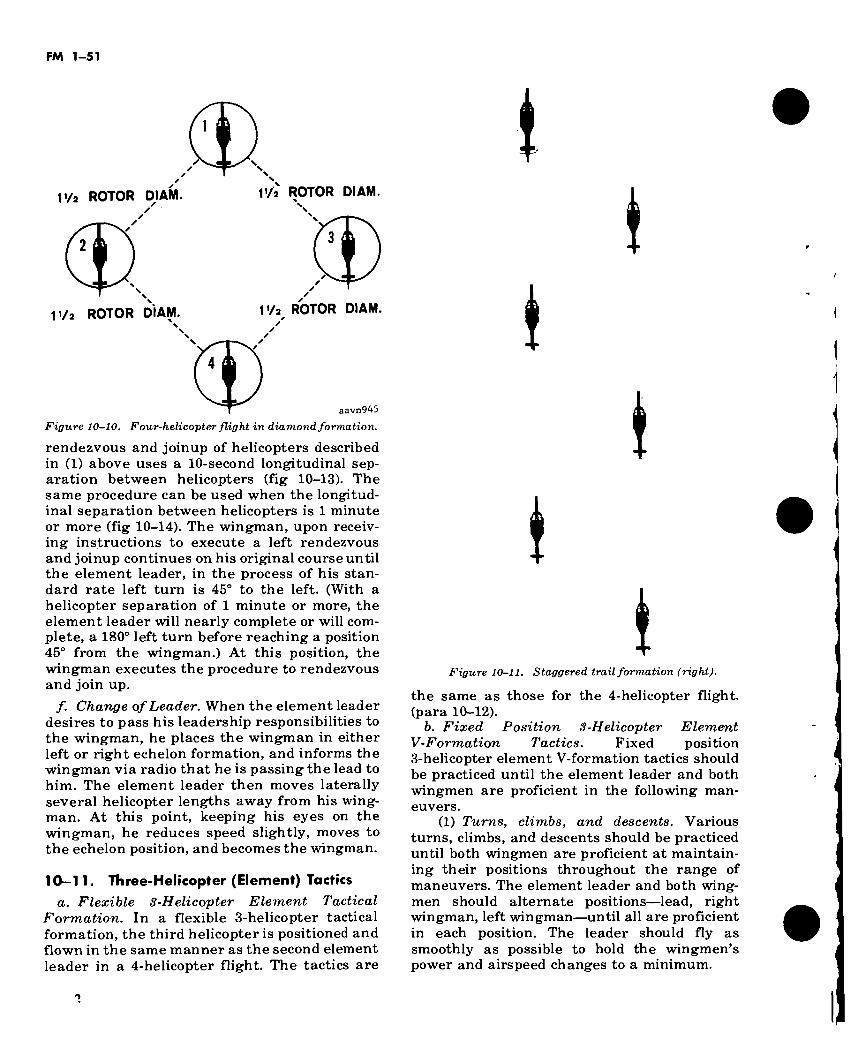
FM 1-51
1
l'/a ROTOR DI AM. IVa ROTOR DI AM
1 i/a ROTOR DIAM. l'/a ROTOR DIAM.
"W aavn945
Figure 10-10, Four-helicopter flight in diamond formation.
rendezvous and joinup of helicopters described in (1) above uses a 10-second longitudinal sep- aration between helicopters (fig 10-13). The same procedure can be used when the longitud- inal separation between helicopters is 1 minute or more (fig 10-14). The wingman, upon receiv- ing instructions to execute a left rendezvous and joinup continues on his original course until the element leader, in the process of his stan- dard rate left turn is 45° to the left. (With a helicopter separation of 1 minute or more, the element leader will nearly complete or will com- plete, a 180° left turn before reaching a position 45° from the wingman.) At this position, the wingman executes the procedure to rendezvous and join up.
/. Change of Leader. When the element leader desires to pass his leadership responsibilities to the wingman, he places the wingman in either left or right echelon formation, and informs the wingman via radio that he is passing the lead to him. The element leader then moves laterally several helicopter lengths away from his wing- man. At this point, keeping his eyes on the wingman, he reduces speed slightly, moves to the echelon position, and becomes the wingman.
10-11. Three-Helicopter (Element) Tactics a. Flexible 3-Helicopter Element Tactical
Formation. In a flexible 3-helicopter tactical formation, the third helicopter is positioned and flown in the same manner as the second element leader in a 4-helicopter flight. The tactics are
i i
i l
! Figure 10-11. Staggered trail formation (right).
the same as those for the 4-helicopter flight, (para 10-12).
b. Fixed Position 3-Helicopter Element V-Formation Tactics. Fixed position 3-helicopter element V-formation tactics should be practiced until the element leader and both wingmen are proficient in the following man- euvers.
(1) Turns, climbs, and descents. Various turns, climbs, and descents should be practiced until both wingmen are proficient at maintain- ing their positions throughout the range of maneuvers. The element leader and both wing- men should alternate positions—lead, right wingman, left wingman—until all are proficient in each position. The leader should fly as smoothly as possible to hold the wingmen’s power and airspeed changes to a minimum.
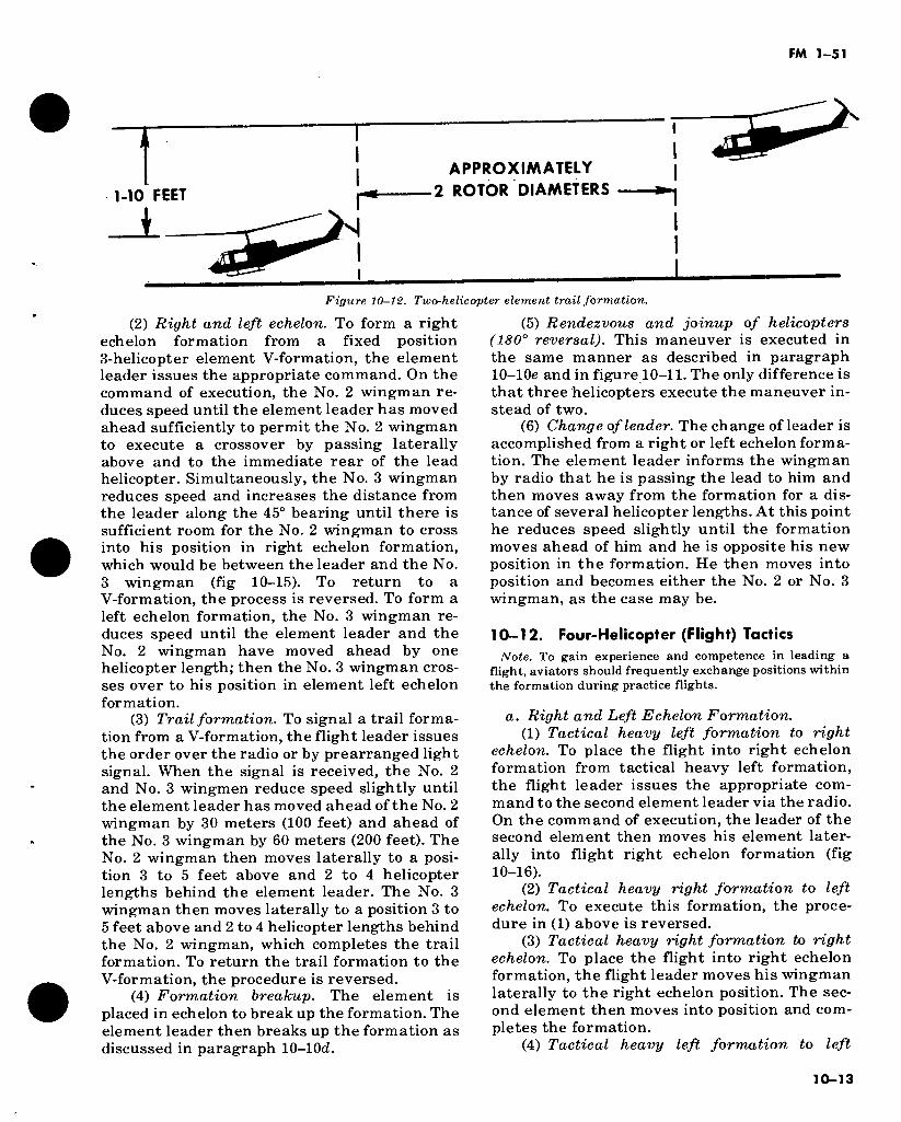
FM 1-51
T 1-10 FEET
I
APPROXIMATELY
2 ROTOR DIAMETERS
Figure 10-12. Two-helicopter element trail formation.
(2) Right and left echelon. To form a right echelon formation from a fixed position 3-helicopter element V-formation, the element leader issues the appropriate command. On the command of execution, the No. 2 wingman re- duces speed until the element leader has moved ahead sufficiently to permit the No. 2 wingman to execute a crossover by passing laterally above and to the immediate rear of the lead helicopter. Simultaneously, the No. 3 wingman reduces speed and increases the distance from the leader along the 45° bearing until there is sufficient room for the No. 2 wingman to cross into his position in right echelon formation, which would be between the leader and the No. 3 wingman (fig 10-15). To return to a V-formation, the process is reversed. To form a left echelon formation, the No. 3 wingman re- duces speed until the element leader and the No. 2 wingman have moved ahead by one helicopter length; then the No. 3 wingman cros- ses over to his position in element left echelon formation.
(3) Trail formation. To signal a trail forma- tion from a V-formation, the flight leader issues the order over the radio or by prearranged light signal. When the signal is received, the No. 2 and No. 3 wingmen reduce speed slightly until the element leader has moved ahead of the No. 2 wingman by 30 meters (100 feet) and ahead of the No. 3 wingman by 60 meters (200 feet). The No. 2 wingman then moves laterally to a posi- tion 3 to 5 feet above and 2 to 4 helicopter lengths behind the element leader. The No. 3 wingman then moves laterally to a position 3 to 5 feet above and 2 to 4 helicopter lengths behind the No. 2 wingman, which completes the trail formation. To return the trail formation to the V-formation, the procedure is reversed.
(4) Formation breakup. The element is placed in echelon to break up the formation. The element leader then breaks up the formation as discussed in paragraph 10-10d.
(5) Rendezvous and joinup of helicopters (180° reversal). This maneuver is executed in the same manner as described in paragraph 10-10e and in figure 10-11. The only difference is that three helicopters execute the maneuver in- stead of two.
(6) Change of leader. The change of leader is accomplished from a right or left echelon forma- tion. The element leader informs the wingman by radio that he is passing the lead to him and then moves away from the formation for a dis- tance of several helicopter lengths. At this point he reduces speed slightly until the formation moves ahead of him and he is opposite his new position in the formation. He then moves into position and becomes either the No. 2 or No. 3 wingman, as the case may be.
10-12. Four-Helicopter (Flight) Tactics Note. To gain experience and competence in leading a
flight, aviators should frequently exchange positions within the formation during practice flights.
a. Right and Left Echelon Formation. (1) Tactical heavy left formation to right
echelon. To place the flight into right echelon formation from tactical heavy left formation, the flight leader issues the appropriate com- mand to the second element leader via the radio. On the command of execution, the leader of the second element then moves his element later- ally into flight right echelon formation (fig 10-16).
(2) Tactical heavy right formation to left echelon. To execute this formation, the proce- dure in (1) above is reversed.
(3) Tactical heavy right formation to right echelon. To place the flight into right echelon formation, the flight leader moves his wingman laterally to the right echelon position. The sec- ond element then moves into position and com- pletes the formation.
(4) Tactical heavy left formation to left
10-13
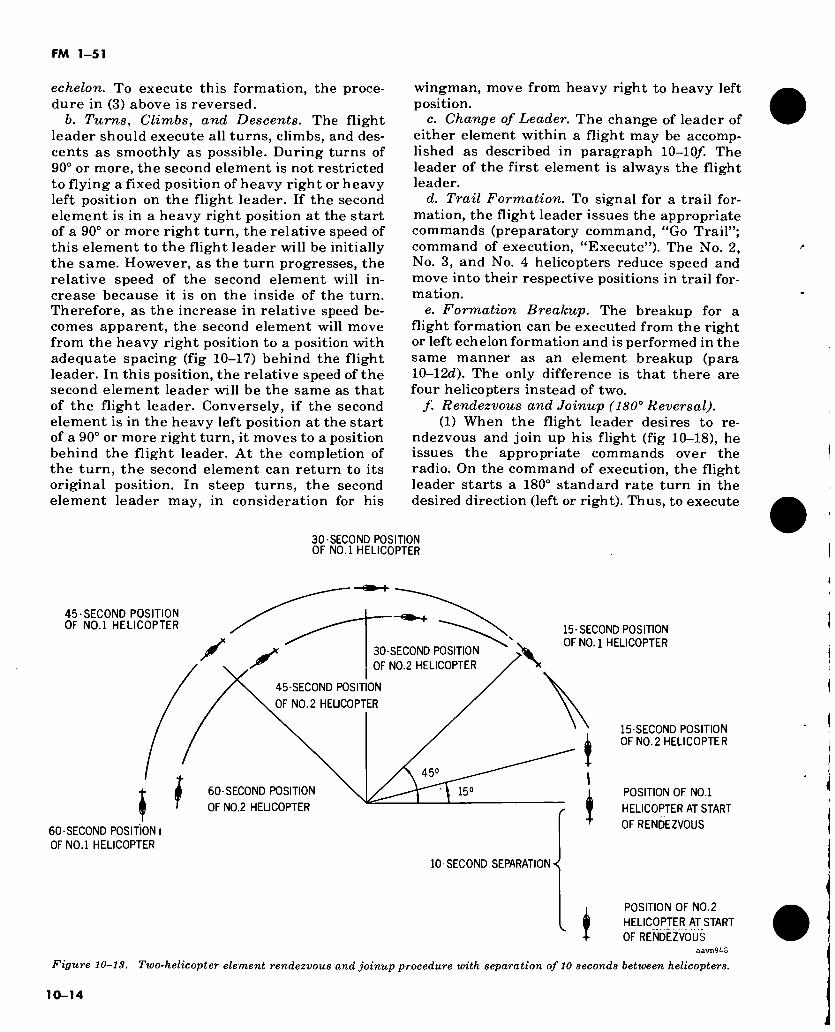
FM 1-51
echelon. To execute this formation, the proce- dure in (3) above is reversed.
b. Turns, Climbs, and Descents. The flight leader should execute all turns, climbs, and des- cents as smoothly as possible. During turns of 90° or more, the second element is not restricted to flying a fixed position of heavy right or heavy left position on the flight leader. If the second element is in a heavy right position at the start of a 90° or more right turn, the relative speed of this element to the flight leader will be initially the same. However, as the turn progresses, the relative speed of the second element will in- crease because it is on the inside of the turn. Therefore, as the increase in relative speed be- comes apparent, the second element will move from the heavy right position to a position with adequate spacing (fig 10-17) behind the flight leader. In this position, the relative speed of the second element leader will be the same as that of the flight leader. Conversely, if the second element is in the heavy left position at the start of a 90° or more right turn, it moves to a position behind the flight leader. At the completion of the turn, the second element can return to its original position. In steep turns, the second element leader may, in consideration for his
wingman, move from heavy right to heavy left position.
c. Change of Leader. The change of leader of either element within a flight may be accomp- lished as described in paragraph 10-10/. The leader of the first element is always the flight leader.
d. Trail Formation. To signal for a trail for- mation, the flight leader issues the appropriate commands (preparatory command, “Go Trail”; command of execution, “Execute”). The No. 2, No. 3, and No. 4 helicopters reduce speed and move into their respective positions in trail for- mation.
e. Formation Breakup. The breakup for a flight formation can be executed from the right or left echelon formation and is performed in the same manner as an element breakup (para 10-12d). The only difference is that there are four helicopters instead of two.
/. Rendezvous and Joinup (180° Reversal). (1) When the flight leader desires to re-
ndezvous and join up his flight (fig 10-18), he issues the appropriate commands over the radio. On the command of execution, the flight leader starts a 180° standard rate turn in the desired direction (left or right). Thus, to execute
30-SECOND POSITION OF N0.1 HELICOPTER
45-SECOND POSITION OF N0.1 HELICOPTER
60-SECOND POSITION)
0FN0.1 HELICOPTER
y 30-SECOND POSITION
OF NO. 2 HELICOPTER
45-SECOND POSITION
OF NO. 2 HELICOPTER
45°
60-SECOND POSITION
OF N0.2 HELICOPTER
15°
10-SECOND SEPARATION
15- SECOND POSITION OF NO. 1 HELICOPTER
15-SECOND POSITION OF NO. 2 HELICOPTER
POSITION OF N0.1
HELICOPTER AT START
OF RENDEZVOUS
POSITION OF NO. 2
HELICOPTER AT START
OF RENDEZVOUS aavn94S
Figure 10-13. Two-helicopter element rendezvous and joinup procedure with separation of 10 seconds between helicopters.
10-14
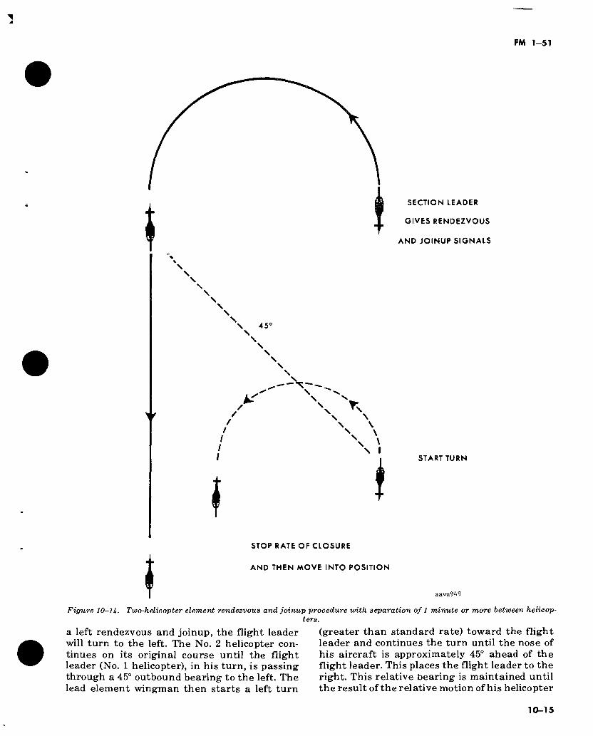
SECTION LEADER Í GIVES RENDEZVOUS
AND JOINUP SIGNALS
\
N S \ 45° \ \ \ \ \
^ Nv s \ \ \
Í i START TURN
STOP RATE OF CLOSURE
AND THEN MOVE INTO POSITION
aavn949
Figure 10-1U. Two-helicopter element rendezvous and joinup procedure vñth separation of 1 minute or more between helicop- ters.
a left rendezvous and joinup, the flight leader will turn to the left. The No. 2 helicopter con- tinues on its original course until the flight leader (No. 1 helicopter), in his turn, is passing through a 45° outbound bearing to the left. The lead element wingman then starts a left turn
(greater than standard rate) toward the flight leader and continues the turn until the nose of his aircraft is approximately 45° ahead of the flight leader. This places the flight leader to the right. This relative bearing is maintained until the result of the relative motion of his helicopter
10-15
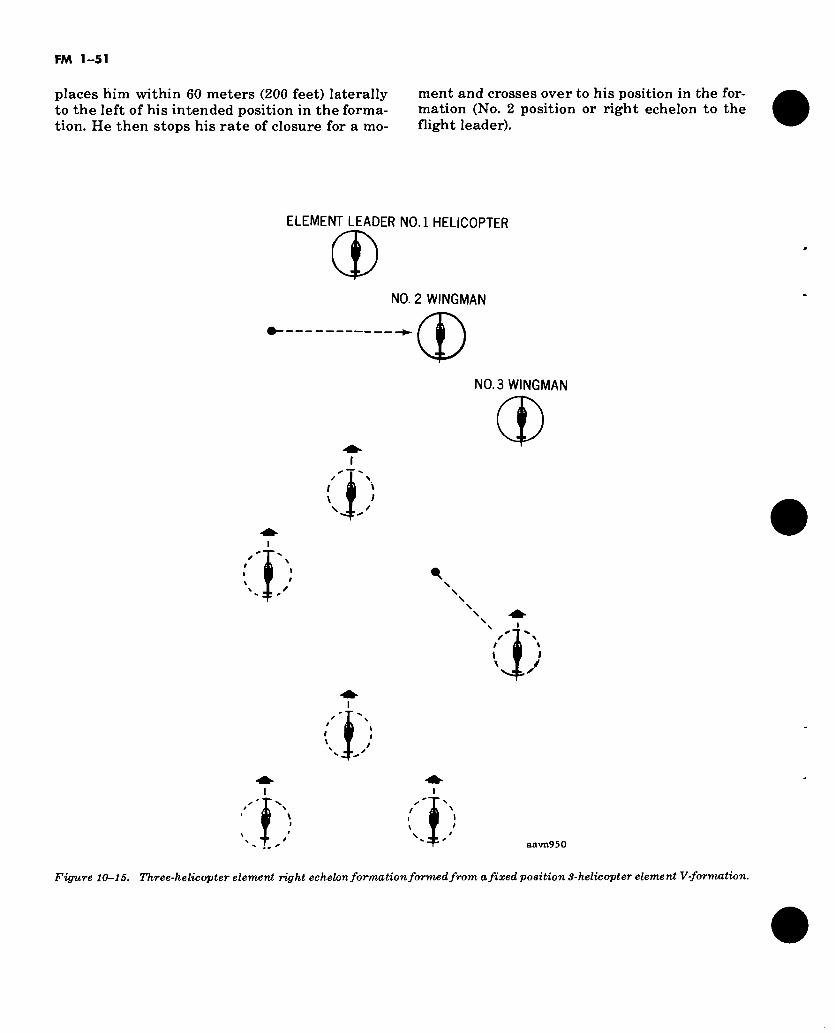
FM 1-51
places him within 60 meters (200 feet) laterally to the left of his intended position in the forma- tion. He then stops his rate of closure for a mo-
ment and crosses over to his position in the for- mation (No. 2 position or right echelon to the flight leader).
ELEMENT LEADER N0.1 HELICOPTER
(£>
4)
NO. 2 WINGMAN
-*(£> NO. 3 WINGMAN
4)
4:
t 4;
aavn950
Figure 10—15. Three-helicopter element right echelon formation formed from a fixed position 3-helicopter element V-formation.
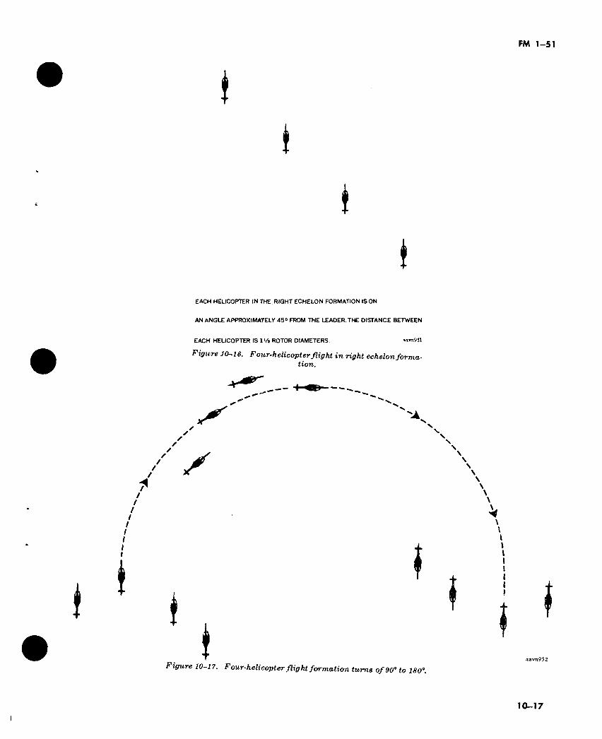
FM 1-51
I t
I (
EACH HELICOPTER IN THE, RIGHT ECHELON FORMATION IS ON
AN ANGLE APPROXIMATELY 45° FROM THE LEADER.THE DISTANCE BETWEEN
EACH HELICOPTER IS IVa ROTOR DIAMETERS. »avn951
Figure 10-16. F our-helicopter flight in right echelon forma- tion.
S'
/ X
I *
I it
I Figure 10-17. Four-helicopter flight formation turns of 90° to 180°.
aavn952
10-17
FM 1-51
(2) When the second element leader (No. 3 helicopter) receives instructions from the flight leader to execute a left rendezvous and joinup, he continues on his original course until the flight leader has reached a position 45° to the left of him. (If properly executing the rendezv- ous and joinup procedure, the lead element wingman will be approximately on a 45° bearing from the second element leader.) The second element leader then starts a turn toward the flight leader and continues the turn until the nose of his helicopter is approximately 45° ahead of the flight leader. This places the flight leader to the right. The second element leader main- tains the relative bearing until the relative mo- tion of his helicopter places him 60 meters (200 feet) laterally to the left of his intended position in the formation. The second element leader then stops his rate of closure for a moment and moves into his position in the formation.
(3) When the second element wingman (No. 4 helicopter) receives instructions that the flight will execute a rendezvous and joinup, he continues on his original course until the flight leader has reached a position that bears 45° to the left. (When properly executing the rendezv- ous and joinup procedure, the No. 2 and No. 3 helicopters will also be in close vicinity to the flight leader and thus can be considered to bear 45° from the No. 4 helicopter.) The No. 4 wing- man then starts a turn toward the flight leader and continues the turn until the nose of his helicopter is approximately 45° ahead of the flight leader. This places the flight leader to the right. The second element wingman maintains this position until the relative motion of his helicopter places him 60 meters (200 feet) later- ally to the left of his intended position in the formation. He then stops his rate of closure for a moment and moves into position. To execute a right turn rendezvous and joinup, the proce- dures for the left turn are reversed.
(4) Normally, after a formation breakup the longitudinal separation between helicopters is not more than 5 to 15 seconds. The procedure for rendezvous and joinup described in (1) through (3) above uses a 10-second longitudinal separa- tion between helicopters (fig 10-18). The same procedures can be used when the longitudinal separations between helicopters are 1 minute or more. The only differnece is that the flight leader, in a Iminute separation, will complete a 180° turn before he consecutively bears 45° from the other helicopters (fig 10-19).
10-13. Five- and Six-Helicopter (Flight) Tac- tics
a. Tactical Free Cruise Formations. Tactics for the 5- and 6-helicopter tactical flight forma- tions (capable of free cruise) (para 10-115) are the same as discussed in paragraph 10-14 for 4-helicopter (flight) tactics.
b. Six-Helicopter Flight (Fixed Position) Formation. Six-helicopter flight (fixed position) formation tactics should be practiced until the flight leader, the second element leader, and all wingmen are proficient in the following man- euvers:
(1) Rendezvous and joinup (180° reversal). To rendezvous and join up the flight from a trail formation (fig 10-20), the flight leader informs the members of the flight of his intentions. The flight leader then begins a 180° standard rate turn to the left or right. To execute a left re- ndezvous and joinup, the flight leader will turn to the left; for a right rendezvous and joinup, he will turn to the right. The other helicopters con- tinue on the original course until the flight leader, in consecutive order, is 45° from each individual helicopter. As the flight leader reaches this position relative to each helicopter, that helicopter starts a turn toward the flight leader and continues the turn until the nose of the helicopter is approximately 45° ahead of the flight leader. This heading is then maintained until the helicopter is within approximately 60 meters (200 feet) laterally of its intended posi- tion in the formation. At this point the rate of closure is stopped for a moment, and the aviator moves his helicopter laterally into position within the formation.
(2) Turns, climbs, and descents. During nor- mal turns, climbs, and descents, the second ele- ment leader and all wingmen must maintain their positions and spacing by adjusting power and airspeed as necessary. The flight leader should fly as smoothly as possible so that the wingmen’s power and airspeed adjustments are kept to a minimum. The maneuverability of the column of vees formation will increase greatly as the individual pilots become proficient in formation flying.
(3) Trail formation. To place the flight into trail formation from a column of vees, the flight leader issues the appropriate commands. The No. 2 and No. 3 wingmen and the second ele- ment reduce speed slightly. The No. 2 wingman allows the flight leader to move ahead of him 2 to 4 helicopter lengths, then moves laterally to a position 3 to 5 feet above and 2 to 4 helicopter lengths behind the flight leader. The No. 3
10-18
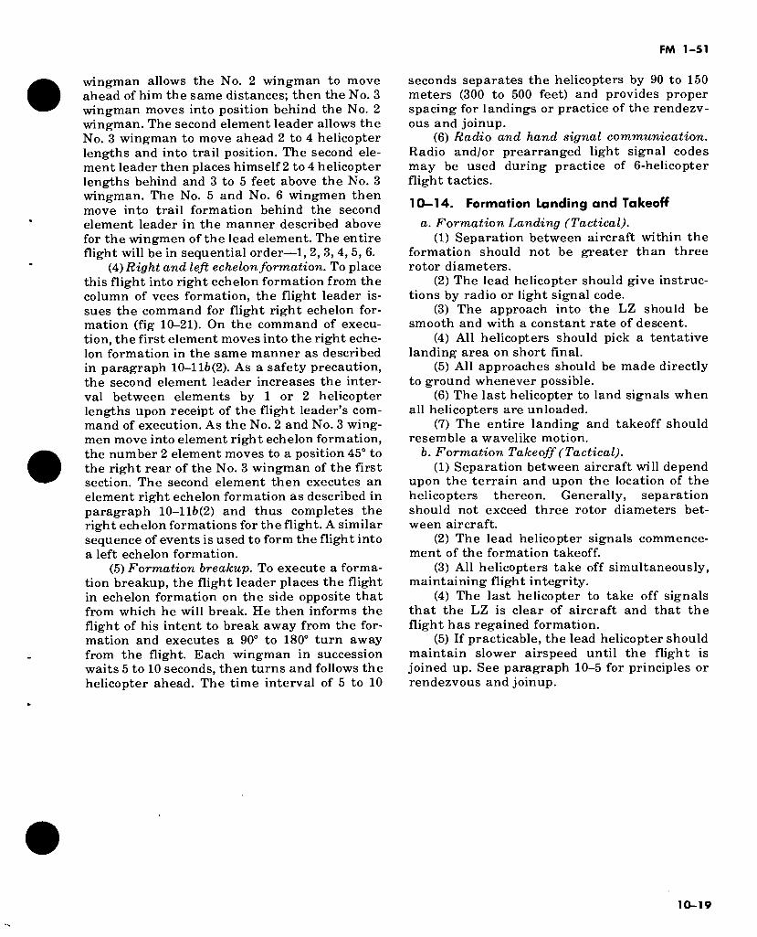
FM 1-51
wingman allows the No. 2 wingman to move ahead of him the same distances; then the No. 3 wingman moves into position behind the No. 2 wingman. The second element leader allows the No. 3 wingman to move ahead 2 to 4 helicopter lengths and into trail position. The second ele- ment leader then places himself 2 to 4 helicopter lengths behind and 3 to 5 feet above the No. 3 wingman. The No. 5 and No. 6 wingmen then move into trail formation behind the second element leader in the manner described above for the wingmen of the lead element. The entire flight will be in sequential order—1, 2, 3, 4, 5, 6.
(4) Right and left echelon formation. To place this flight into right echelon formation from the column of vees formation, the flight leader is- sues the command for flight right echelon for- mation (fig 10-21). On the command of execu- tion, the first element moves into the right eche- lon formation in the same manner as described in paragraph 10-lli>(2). As a safety precaution, the second element leader increases the inter- val between elements by 1 or 2 helicopter lengths upon receipt of the flight leader’s com- mand of execution. As the No. 2 and No. 3 wing- men move into element right echelon formation, the number 2 element moves to a position 45° to the right rear of the No. 3 wingman of the first section. The second element then executes an element right echelon formation as described in paragraph 10-116(2) and thus completes the right echelon formations for the flight. A similar sequence of events is used to form the flight into a left echelon formation.
(5) Formation breakup. To execute a forma- tion breakup, the flight leader places the flight in echelon formation on the side opposite that from which he will break. He then informs the flight of his intent to break away from the for- mation and executes a 90° to 180° turn away from the flight. Each wingman in succession waits 5 to 10 seconds, then turns and follows the helicopter ahead. The time interval of 5 to 10
seconds separates the helicopters by 90 to 150 meters (300 to 500 feet) and provides proper spacing for landings or practice of the rendezv- ous and joinup.
(6) Radio and hand signal communication. Radio and/or prearranged light signal codes may be used during practice of 6-helicopter flight tactics.
10-14. Formation Landing and Takeoff а. Formation Landing (Tactical).
(1) Separation between aircraft within the formation should not be greater than three rotor diameters.
(2) The lead helicopter should give instruc- tions by radio or light signal code.
(3) The approach into the LZ should be smooth and with a constant rate of descent.
(4) All helicopters should pick a tentative landing area on short final.
(5) All approaches should be made directly to ground whenever possible.
(6) The last helicopter to land signals when all helicopters are unloaded.
(7) The entire landing and takeoff should resemble a wavelike motion.
б. Formation Takeoff (Tactical). (1) Separation between aircraft will depend
upon the terrain and upon the location of the helicopters thereon. Generally, separation should not exceed three rotor diameters bet- ween aircraft.
(2) The lead helicopter signals commence- ment of the formation takeoff.
(3) All helicopters take off simultaneously, maintaining flight integrity.
(4) The last helicopter to take off signals that the LZ is clear of aircraft and that the flight has regained formation.
(5) If practicable, the lead helicopter should maintain slower airspeed until the flight is joined up. See paragraph 10-5 for principles or rendezvous and joinup.
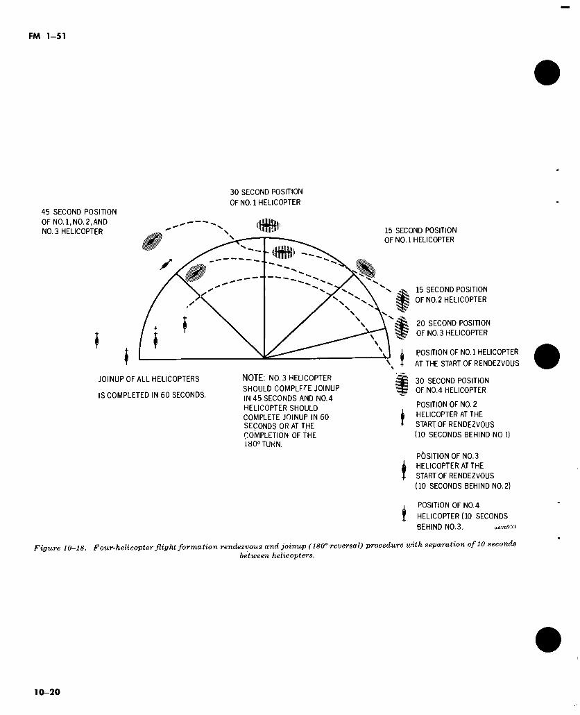
FM 1-51
30 SECOND POSITION
OF NO.l HELICOPTER
45 SECOND POSITION
OF NO.l,NO.2,AND
NO. 3 HELICOPTER
î
y
15 SECOND POSITION
OF NO.l HELICOPTER
15 SECOND POSITION
OF N0.2 HELICOPTER
20 SECOND POSITION
OF NO. 3 HELICOPTER
POSITION OF NO.l HELICOPTER
AT THE START OF RENDEZVOUS
JOINUP OF ALL HELICOPTERS
IS COMPLETED IN 60 SECONDS.
NOTE: NO. 3 HELICOPTER
SHOULD COMPLFrE JOINUP
IN 45 SECONDS AND N0.4
HELICOPTER SHOULD COMPLETE JOINUP IN 60 SECONDS OR AT THE COMPLETION OF THE 180° TURN.
■ 30 SECOND POSITION OF NO.4 HELICOPTER
POSITION OF NO. 2
k HELICOPTER AT THE
+ START OF RENDEZVOUS
(10 SECONDS BEHIND NO 1)
PÖSITION OF NO.3
¿ HELICOPTER AT THE
* START OF RENDEZVOUS
(10 SECONDS BEHIND NO. 2)
POSITION OF NO. 4
HELICOPTER (10 SECONDS
BEHIND NO.3, aavn953
Figure 10-18. Four-helicopter flight formation rendezvous and joinup ( 180° reversal) procedure with separation of 10 seconds between helicopters.
10-20
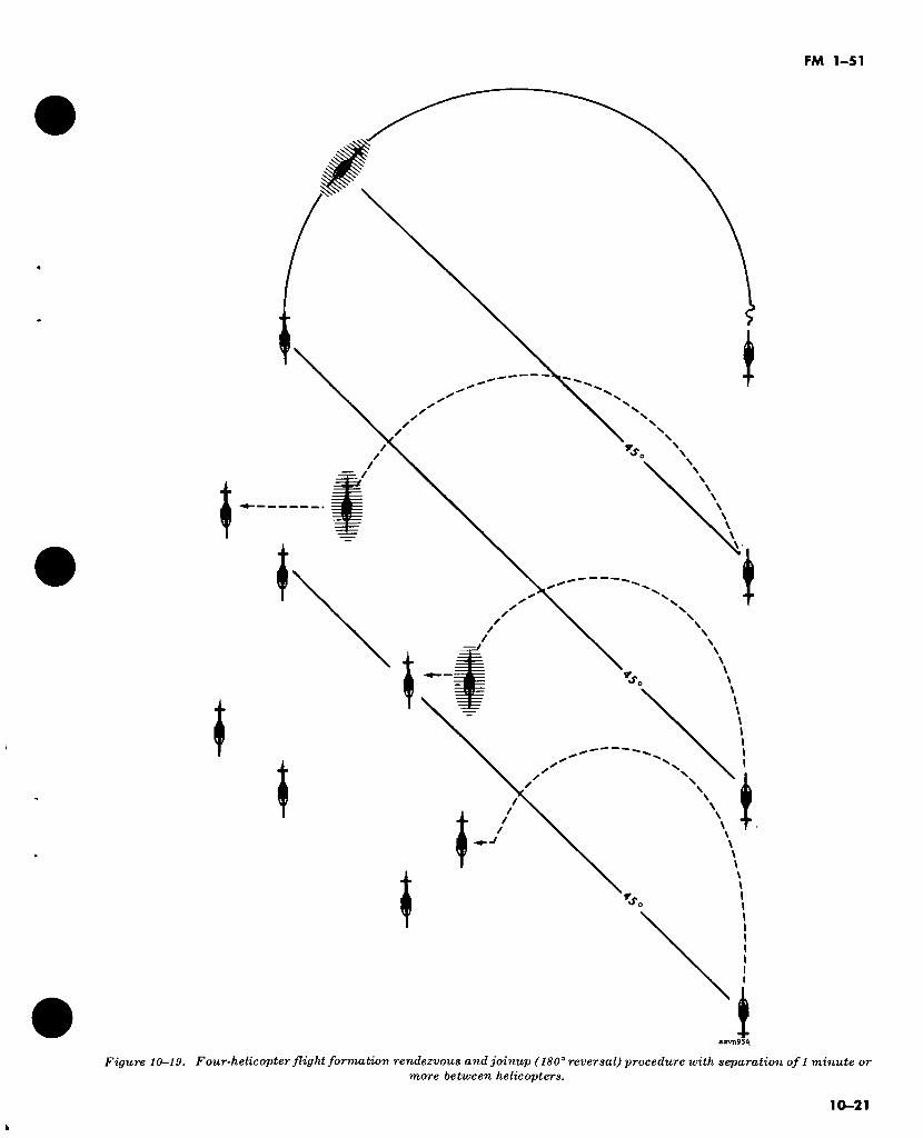
FM 1-51
♦
SS
Figure 10-19. Four-helicopter flight formation rendezvous and joinup (180° reversal) procedure with separation of 1 minute or more between helicopters.
10-21
k
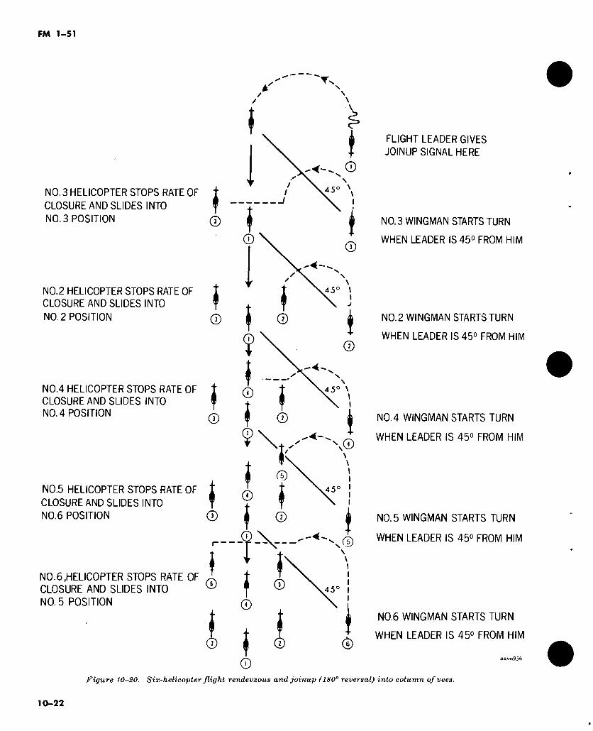
FM 1-51
NO. 3 HELICOPTER STOPS RATE OF
CLOSURE AND SLIDES INTO
NO. 3 POSITION
NO.2 HELICOPTER STOPS RATE OF CLOSURE AND SLIDES INTO
NO. 2 POSITION
NO.4 HELICOPTER STOPS RATE OF
CLOSURE AND SLIDES INTO NO. 4 POSITION
NO.5 HELICOPTER STOPS RATE OF
CLOSURE AND SLIDES INTO
NO.6 POSITION
f
Í ®
I CD
I ®
4 5
©
45° \
Q
®
®
NO.6,HELICOPTER STOPS RATE OF CLOSURE AND SLIDES INTO
NO. 5 POSITION
©
f ©
45° \ ©
.. * ©
♦ \+ ^^'N©
'
© o I 45
©
©
©
l © 45°
©
FLIGHT LEADER GIVES
JOINUP SIGNAL HERE
NO.3 WINGMAN STARTS TURN
WHEN LEADER IS 45° FROM HIM
NO.2 WINGMAN STARTS TURN
WHEN LEADER IS 45° FROM HIM
N0.4 WINGMAN STARTS TURN
WHEN LEADER IS 45° FROM HIM
NO.5 WINGMAN STARTS TURN
WHEN LEADER IS 45° FROM HIM
©
NO.6 WINGMAN STARTS TURN
WHEN LEADER IS 45° FROM HIM
Figure 10-20. Six-helicopter flight rendevzous and joinup ( 180° reversal) into column of vees.
10-22
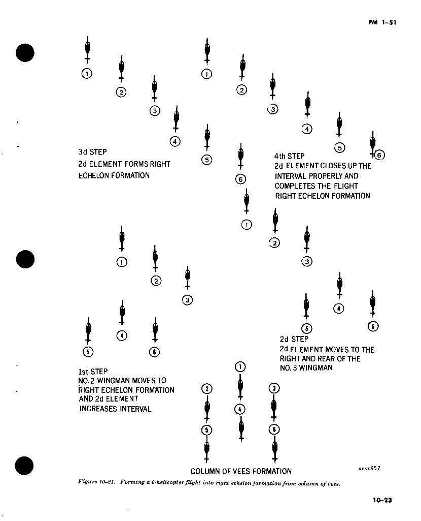
FM 1-51
J © I I
t ©
t ©
3d STEP
2d ELEMENT FORMS RIGHT
ECHELON FORMATION
f ©
f ©
I ©
I ©
©
t ©
i 1
©
1st STEP
NO. 2 WINGMAN MOVES TO
RIGHT ECHELON FORMATION AND 2d ELEMENT
INCREASES INTERVAL
©
i ©
i
t ©
t ©
* ©
©
i ©
»
t © t
© * ©
4th STEP
2d ELEMENT CLOSES UP THE
INTERVAL PROPERLY AND
COMPLETES THE FLIGHT
RIGHT ECHELON FORMATION
ti)
f © t
©
i t © t
© © 2d STEP
2d ELEMENT MOVES TO THE
RIGHT AND REAR OF THE NO. 3 WINGMAN
©
i ©
COLUMN OFVEES FORMATION
figure 10-21. Forming a 6-helicopter flight into right echelon formation from column ofvees.
aavn957
10-23
FM 1-51
Section V. INADVERTENT INSTRUMENT FLIGHT CONDITIONS
10-15. General
If either marginal VFR or IFR weather is fore- cast, positive radio communications should be established and maintained with all helicopters in the formation. All turns and climbs should be accomplished at a predetermined standard rate.
10—16. Entering IFR Conditions That Permit Visual Contact
When instrument flight conditions permit the helicopters in formation to remain in visual con- tact with each other, one of the following proce- dures may be used:
a. The formation leader may decide to con- tinue and complete the mission, provided each member of the formation is instrument qual- ified.
b. The formation leader may elect to perform a 180° formation turn out of the IFR condition.
10-17. Entering IFR Conditions That Destory Visual Contact
When instrument flight conditions are entered which instantly destroy all visual contact bet- ween the helicopters in the formation, each av- iator (as simultaneously as possible) must im- mediately initiate the maneuver designed for his respective position (fig 10-22).
10-18. IFR Breakup Procedures
a. The duties of the formation leader do not require him to observe the other helicopters with as much constancy as they must observe one another. Therefore, the formation leader depends on a member of the flight (usually the No. 3 helicopter) to announce over the radio: “Visual contact impossible . . . executing IFR breakup procedures.” Upon receipt of this statement the following procedural actions are taken:
(1) The flight leader continues straight ahead and reports his magnetic heading and altitude.
(2) The lead element wdngman executes a 30° turn away from the flight leader, and climbs 100 feet.
(3) The second element leader (the No. 3 helicopter) executes a 30° climbing turn away from the leader, and climbs 200 feet.
(4) The wingman of the second element (the No. 4 helicopter) executes a 60° climbing turn away from his leader, and climbs 300 feet.
Note. As an added safety precaution, the wingman of the second element should reduce airspeed slightly (approx- imately 10 knots) following the moment of losing visual con- tact.
(5) After all helicopters have completed the initial breakaway turn and climbed to their as- signed altitude, they fly a straight course for 30 seconds. The flight leader then commands over the radio “No 2 and No. 4 helicopters, complete 180° turn.” The No. 2 and No. 4 helicopters ack- nowledge the communication and continue their turn until they have completed a 180° turn from the original heading of the formation.
(6) After ordering the No. 2 and No. 4 helicopters to complete the 180° turn, the flight leader waits 10 seconds and instructs the No. 3 helicopter to complete his 180° turn. Simultane- ously, the flight leader starts his own right 180° turn.
(7) When the pilot of the helicopter at the lowest altitude reports that he has reached VFR conditions, the helicopter at the next higher al- titude can start a descent to VFR conditions. This sequence is continued until all helicopters report to the leader that they are VFR, giving their location if known. The flight leader can then proceed to rendezvous and join up the for- mation.
b. This procedure for formation breakup upon encountering instrument weather will provide both altitude and lateral separation of all air- craft. However, if all aviators cannot, for exam- ple, maintain altitude within plus or minus 100 feet, the lateral separation as provided is still sufficient to prevent midair collisions.
c. Since all helicopters may not lose visual contact at the same time, the aviator that first loses visual contact should identify himself to the flight leader and announce that he is ex- ecuting IFR breakup procedure (for his position in the formation, as set forth above).
Section VI. NIGHT FORMATION FLYING
10-19. General hours prior to conducting night training. To re-
a. Night formation flying requires a higher duce the hazards of night formation flying and degree of proficiency and alertness than day effect smooth teamwork, careful planning and a formation flying. Aviators should be trained in thorough briefing of participating aviators the basics of formation flying during daylight should be accomplished before takeoff.
10-24
FM 1-51
b. The silhouette of a helicopter cannot be seen except at a dangerously close distance; the only points of reference are the navigation lights. Aviators should not start at one light but should cross-reference two or more lights and scan the entire helicopter to avoid vertigo or autohypnosis while engaged in night formation flying.
c. Night formations must be controlled by radio or prearranged light signal codes. The rotating beacon should be turned off and the running light on dim.
d. Night formation procedures for a 4-helicopter flight are described below. These procedures generally can be applied to any size formation.
10-20. Rendezvous and Joinup of Aircraft (180° Reversal)
a. To rendezvous and join up his flight (fig 10-23), the flight leader signals his intention by radio or prearranged light signal code. He then starts a 180° standard-rate turn in the desired direction of rendezvous and joinup. Thus, to execute a left rendezvous and joinup, the flight leader turns to the left. The No. 2 wingman con- tinues on his original course until the flight leader, in his turn, is passing through a 20° to 30° point to the left. The No. 2 wingman then starts a left turn toward the flight leader and con- tinues the turn until the nose of his helicopter is approximately 20° to 30° ahead of the flight leader. This places the flight leader to the right. The No. 2 wingman maintains this heading until he is approximately 60° and 2 to 4 helicopter lengths to the left rear of the flight leader. He then stops his rate of closure for a moment and crosses over to his position of right echelon on the flight leader.
b. When the second element leader (No. 3 helicopter) receives instructions from the flight leader to execute a left rendezvous and joinup, he continues on his original course until the No. 2 wingman, in his turn, reaches a position 20° to 30° from him to the left. The second element leader then starts a turn toward the No. 2 wingman, and continues the turn until the nose of his helicopter is approximately 20° to 30° ahead of the No. 2 wingman. This now places the No. 2 helicopter to the right. The second element leader maintains this heading until he is within 30 meters (100 feet) of his intended position in the formation. He then slows his rate of closure and moves into position. The second element
leader’s wingman (no. 4 helicopter) executes a rendezvous and joinup in a similar manner.
c. To execute a right rendezvous and joinup, the procedures in a and b above are reversed.
d. The differences between night and day re- ndezvous and joinup are—
(1) At night, a 20° to 30° interception angle is used instead of the 45° angle used during the day. Therefore, more time is required to effect a rendezvous and joinup. The 20° to 30° angle permits, as a safety precaution, the joining helicopters to approach the formation at a slight angle somewhat from the rear.
(2) At night, each helicopter waits until the one immediately ahead turns 20° to 30° before initiating its own procedures to rendezvous and joinup. The aviator in each successive helicop- ter always keeps the one immediately ahead in view.
(3) Aviators executing a rendezvous and joinup on a dark, moonless night must take care that their rate of closure is slow enough to be stopped instantly, and that they do not overrun the helicopter immediately ahead.
(4) A rendezvous will take longer to effect at night. The flight leader must make all his turns standard rate or less, and should never make any abrupt movements. Unless all av- iators in the flight are exceptionally well trained, all heading changes of 30° or more should be announced by the leader prior to ef- fecting the turn.
e. Separation and bearing of aircraft in night formation flying is the same as for day opera- tions.
10-21. Formation Breakup When approaching the field for a night forma-
tion breakup preparatory to landing, the flight leader places the flight in a trail formation. This is the easiest and safest formation for executing a breakup at night. A breakup execute from an echelon formation involving more than two helicopters should not be attempted unless all flight members are exceptionally well trained. Prior to executing a formation breakup, the flight leader should indicate his intentions either by radio communication or by a prear- ranged signal code. Sufficient interval between helicopters must be maintained in order to land the flight expeditiously and prevent the possi- bility of a go around. Night formation landings require special training and should be attemp- ted only by aviators proficient in night landings.
10-25
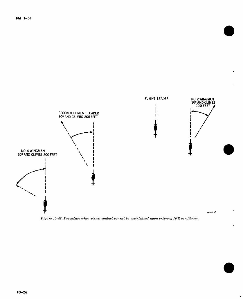
FM 1-51
SECOND ELEMENT LEADER 30° AND CLIMBS 200 FEET
NO. 4 WINGMAN 60° AND CLIMBS 300 FEET
\
*
FLIGHT LEADER NO. 2 WINGMAN 30° AND CLIMBS
100 FEET y
/ /
t
aavn955
Figure 10-22. Procedure when visual contact cannot be maintained upon entering IFR conditions.
10-26
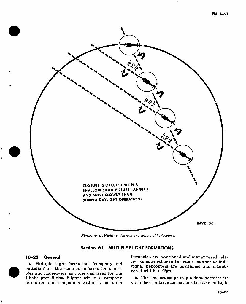
FM 1-51
% *7 N
N V % S N N % % % % X X
£ X X X X X X X X X X X X X X X X X X X X X X X X X X X X X X X
£> X X X X X
X X
X X
X X
X X
X X
X X
X X
CLOSURE IS EFFECTED WITH A SHALLOW SIGHT PICTURE ( ANGLE )
AND MORE SLOWLY THAN DURING DAYLIGHT OPERATIONS
aavn958
Figure 10-23. Night rendezvous and joinup of helicopters.
Section VII. MULTIPLE FLIGHT FORMATIONS
10-22. General
a. Multiple flight formations (company and battalion) use the same basic formation princi- ples and maneuvers as those discussed for the 4-helicopter flight. Flights within a company formation and companies within a battalion
formation are positioned and maneuvered rela- tive to each other in the same manner as indi- vidual helicopters are positioned and maneu- vered within a flight.
b. The free-cruise principle demonstrates its value best in large formations because multiple
10-27
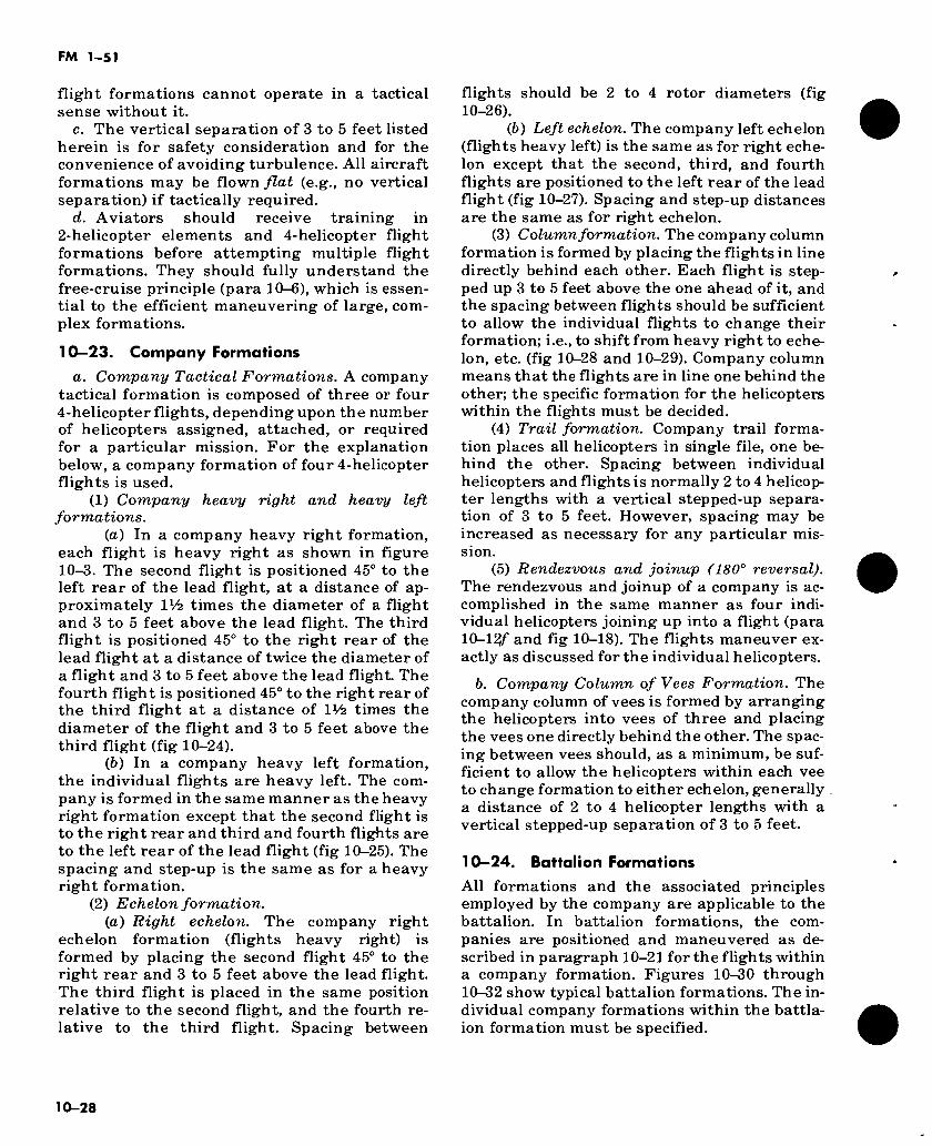
FM 1-51
flight formations cannot operate in a tactical sense without it.
c. The vertical separation of 3 to 5 feet listed herein is for safety consideration and for the convenience of avoiding turbulence. All aircraft formations may be flown flat (e.g., no vertical separation) if tactically required.
d. Aviators should receive training in 2-helicopter elements and 4-helicopter flight formations before attempting multiple flight formations. They should fully understand the free-cruise principle (para 10-6), which is essen- tial to the efficient maneuvering of large, com- plex formations.
10-23. Company Formations
a. Company Tactical Formations. A company tactical formation is composed of three or four 4-helicopter flights, depending upon the number of helicopters assigned, attached, or required for a particular mission. For the explanation below, a company formation of four 4-helicopter flights is used.
(1) Company heavy right and heavy left formations.
(а) In a company heavy right formation, each flight is heavy right as shown in figure 10-3. The second flight is positioned 45° to the left rear of the lead flight, at a distance of ap- proximately IV2 times the diameter of a flight and 3 to 5 feet above the lead flight. The third flight is positioned 45° to the right rear of the lead flight at a distance of twice the diameter of a flight and 3 to 5 feet above the lead flight. The fourth flight is positioned 45° to the right rear of the third flight at a distance of IV2 times the diameter of the flight and 3 to 5 feet above the third flight (fig 10-24).
(б) In a company heavy left formation, the individual flights are heavy left. The com- pany is formed in the same manner as the heavy right formation except that the second flight is to the right rear and third and fourth flights are to the left rear of the lead flight (fig 10-25). The spacing and step-up is the same as for a heavy right formation.
(2) Echelon formation. (a) Right echelon. The company right
echelon formation (flights heavy right) is formed by placing the second flight 45° to the right rear and 3 to 5 feet above the lead flight. The third flight is placed in the same position relative to the second flight, and the fourth re- lative to the third flight. Spacing between
flights should be 2 to 4 rotor diameters (fig 10-26).
(6) Left echelon. The company left echelon (flights heavy left) is the same as for right eche- lon except that the second, third, and fourth flights are positioned to the left rear of the lead flight (fig 10-27). Spacing and step-up distances are the same as for right echelon.
(3) Column formation. The company column formation is formed by placing the flights in line directly behind each other. Each flight is step- ped up 3 to 5 feet above the one ahead of it, and the spacing between flights should be sufficient to allow the individual flights to change their formation; i.e., to shift from heavy right to eche- lon, etc. (fig 10-28 and 10-29). Company column means that the flights are in line one behind the other; the specific formation for the helicopters within the flights must be decided.
(4) Trail formation. Company trail forma- tion places all helicopters in single file, one be- hind the other. Spacing between individual helicopters and flights is normally 2 to 4 helicop- ter lengths with a vertical stepped-up separa- tion of 3 to 5 feet. However, spacing may be increased as necessary for any particular mis- sion.
(5) Rendezvous and joinup (180° reversal). The rendezvous and joinup of a company is ac- complished in the same manner as four indi- vidual helicopters joining up into a flight (para 10-12/" and fig 10-18). The flights maneuver ex- actly as discussed for the individual helicopters.
b. Company Column of Vees Formation. The company column of vees is formed by arranging the helicopters into vees of three and placing the vees one directly behind the other. The spac- ing between vees should, as a minimum, be suf- ficient to allow the helicopters within each vee to change formation to either echelon, generally a distance of 2 to 4 helicopter lengths with a vertical stepped-up separation of 3 to 5 feet.
10-24. Battalion Formations
All formations and the associated principles employed by the company are applicable to the battalion. In battalion formations, the com- panies are positioned and maneuvered as de- scribed in paragraph 10-21 for the flights within a company formation. Figures 10-30 through 10-32 show typical battalion formations. The in- dividual company formations within the battla- ion formation must be specified.
10-28
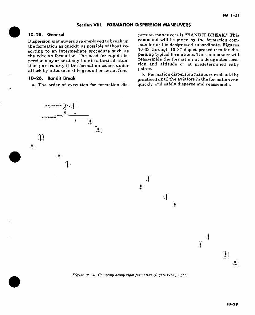
FM 1-51
Section Vlil. FORMATION DISPERSION MANEUVERS
10-25. General
Dispersion maneuvers are employed to break up the formation as quickly as possible without re- sorting to an intermediate procedure such as the echelon formation. The need for rapid dis- persion may arise at any time in a tactical situa- tion, particularly if the formation comes under attack by intense hostile ground or aerial fire.
10-26. Bandit Break
a. The order of execution for formation dis-
persion maneuvers is “BANDIT BREAK.” This command will be given by the formation com- mander or his designated subordinate. Figures 10-33 through 10-37 depict procedures for dis- persing typical formations. The commander will reassemble the formation at a designated loca- tion and altitude or at predetermined rally points.
b. Formation dispersion maneuvers should be practiced until the aviators in the formation can quickly and safely disperse and reassemble.
IV» ROTOR DIAM.i
._Jy L 1 ROTOR DIAM.
$
l
1,
■T 1
•1 •r
t
Figure 10-2U. Company heavy right formation (flights heavy right).
10-29
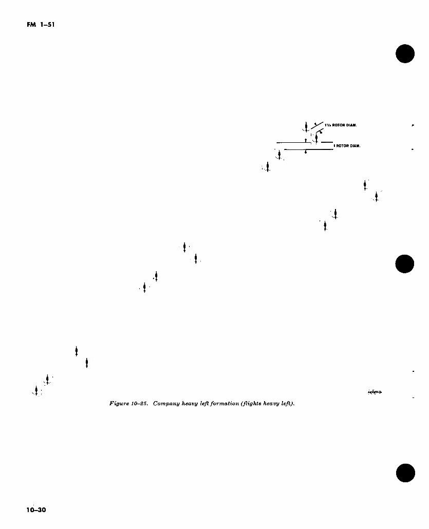
FM 1-51
■4
íí_ Va ROTOR DIAN.
1 ROTOR DIAN.
t .i'
4 I.
r i
•i t
t )
4-
i-: UYB96D>
Figure 10-25. Company heavy left formation (flights heavy left).
10-30
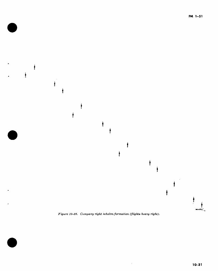
FM 1-51
t !
i t
(
(
t t
I I
i t
I I
Figure 10-26. Company right echelon formation (flights heavy right).
I . I
10-31
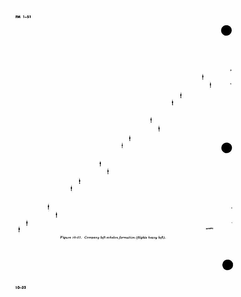
FM 1-51
t I
I I
»
t I
I
( t
i I
(
♦
t t
aavn962
Figure 10-27. Company left echelon formation (flights heavy left).
10-32
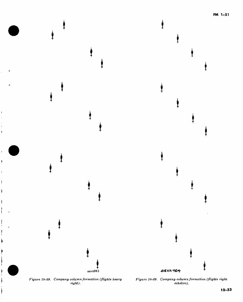
FM 1-51
aavn963
Figure 10-28. Company column formation (flights heavy right).
Figure 10-29. Company column formation (flights right echelon).
10-33
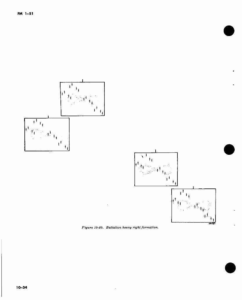
FM 1-51
*V ' J
h
■i .t '
« !
; M ' 1*. ,
¡Êmtp
Figure 10-30. Battalion heavy right formation.
10-34
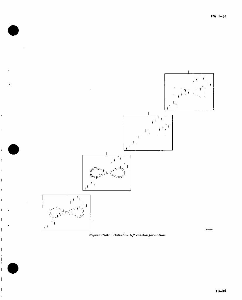
FM 1-51
*
k'-
t-s
t ‘
Figure 10S1. Battalion left echelon formation.
10-35
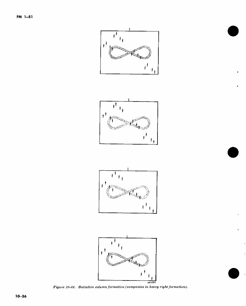
FM 1-51
■if.
» i
%
* I
aavn967
Figure 10-32. Battalion column formation (companies in heavy right formation).
10-36
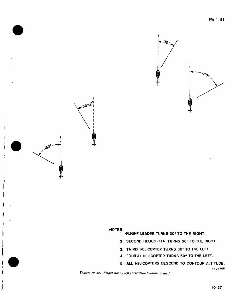
FM 1-51
'*—30o
i
'Oo
/I 30°- •
NOTES: 1. FLIGHT LEADER TURNS 30° TO THE RIGHT.
2. SECOND HELICOPTER TURNS 60° TO THE RIGHT.
3. THIRD HELICOPTER TURNS 30° TO THE LEFT.
4. FOURTH HELICOPTERrTURNS 60° TO THE LEFT.
5. ALL HELICOPTERS DESCEND TO CONTOUR ALTITUDE.
Figure 10-33. Flight heavy left formation “bandit break.
aavn968
10-37
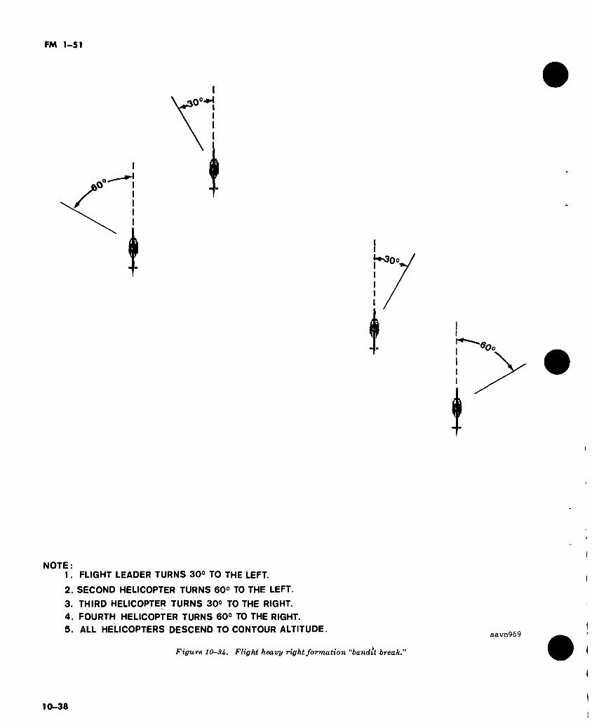
FM 1-51
.O0-*’*
{♦s30o,
'^Oo
I
NOTE: 1. FLIGHT LEADER TURNS 30° TO THE LEFT.
2. SECOND HELICOPTER TURNS 60° TO THE LEFT.
3. THIRD HELICOPTER TURNS 30° TO THE RIGHT.
4. FOURTH HELICOPTER TURNS 60° TO THE RIGHT.
5. ALL HELICOPTERS DESCEND TO CONTOUR ALTITUDE.
Figure 10SU. Flight heavy right formation “bandit break.
aavn969
10-38
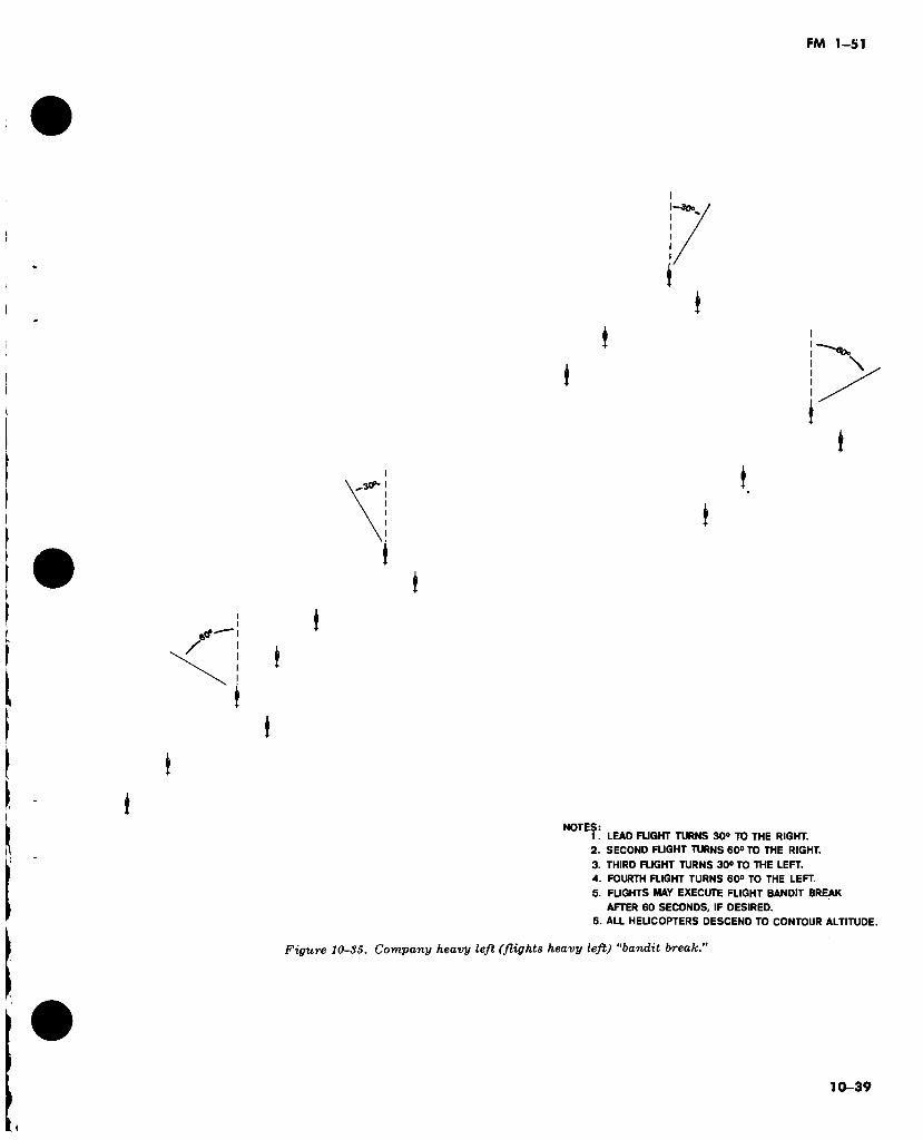
FM 1-51
I
I I
I
i
I 1
* (
I I
(
t
I
:S: 1. LEAD FLIGHT TURNS 30° TO THE RIGHT.
2. SECOND FUGHT TURNS 60° TO THE RIGHT.
3. THIRD FUGHT TURNS 30° TO THE LEFT.
4. FOURTH FLIGHT TURNS 60° TO THE LEFT.
5. FLIGHTS MAY EXECUTE FLIGHT BANDIT BREAK
AFTER 60 SECONDS, IF DESIRED.
6. ALL HELICOPTERS DESCEND TO CONTOUR ALTITUDE.
Figure 10-35. Company heavy left (flights heavy left) "bandit break.”
10-39
i
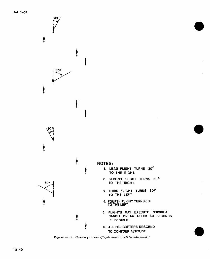
! 60°
60°
NOTES: 1. LEAD FLIGHT TURNS 30°
TO THE RIGHT.
2. SECOND FLIGHT TURNS TO THE RIGHT.
60'
3. THIRD FLIGHT TURNS 30° TO THE LEFT.
4. FOURTH FLIGHT TURNS 60° TO THE LEFT.
5. FLIGHTS MAY EXECUTE INDIVIDUAL ¿ BANDIT BREAK AFTER 60 SECONDS, + IF DESIRED.
J 6. ALL HELICOPTERS DESCEND
TO CONTOUR ALTITUDE.
Figure 10-86. Company column (flights heavy right) “bandit break."
10-40
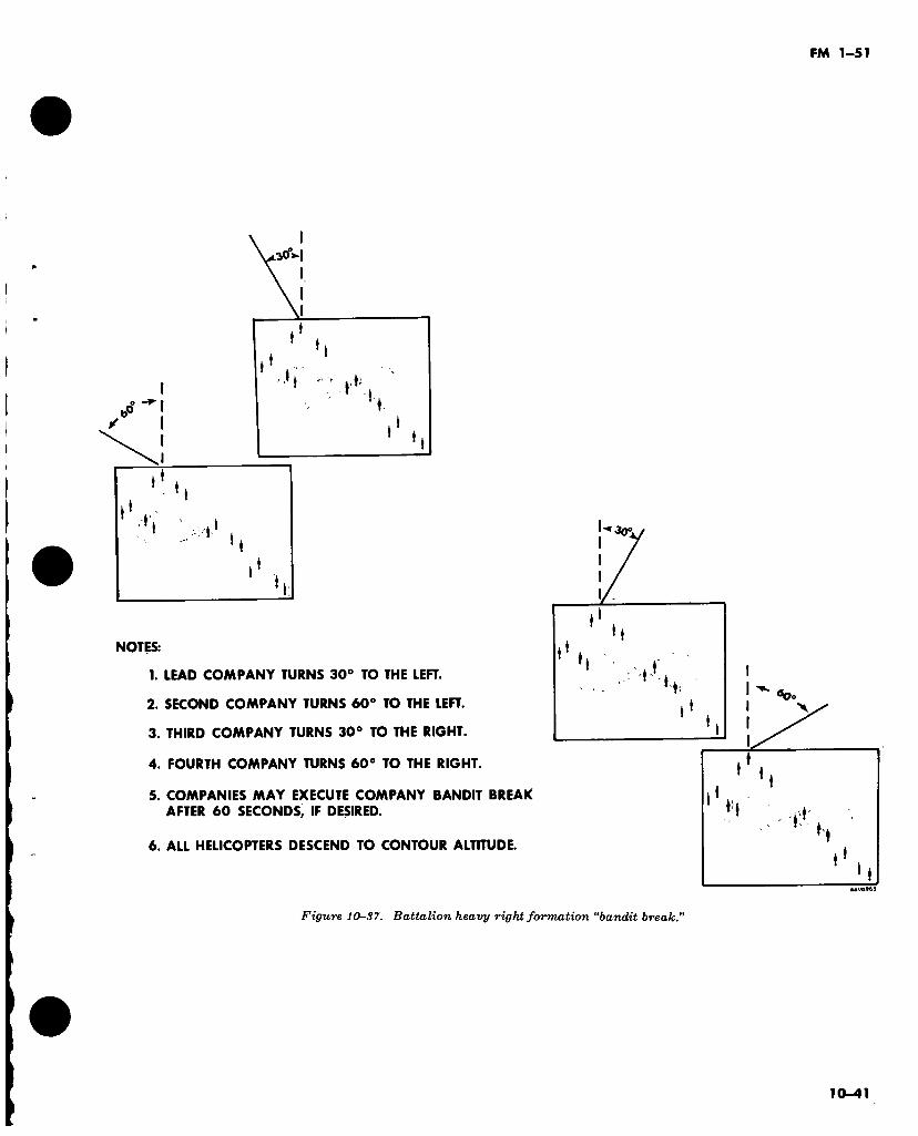
FM 1-51
iCT
‘ !
!
I
NOTES:
1. LEAD COMPANY TURNS 30° TO THE LEFT.
2. SECOND COMPANY TURNS 60° TO THE LEFT.
3. THIRD COMPANY TURNS 30° TO THE RIGHT.
4. FOURTH COMPANY TURNS 60° TO THE RIGHT.
5. COMPANIES MAY EXECUTE COMPANY BANDIT BREAK AFTER 60 SECONDS, IF DESIRED.
6. ALL HELICOPTERS DESCEND TO CONTOUR ALTITUDE.
Jo°
* i
H ■ ii
Figure 10-S7. Battalion heavy right formation “bandit break."
10-41

FM 1-51
CHAPTER 11
PRECAUTIONARY MEASURES AND CRITICAL CONDITIONS
11-1. General Precautionary rules
Because of its unique flight characteristics, a helicopter is capable of many missions no other aircraft can perform. A rotary wing aviator must, however, realize the hazards involved in helicopter flight and know how to apply precau- tions which might save the helicopter or even his life. He should—
a. Check weight and balance prior to flying. b. Assure that any object placed in the cock-
pit of a helicopter is well secured to prevent fouling of the controls.
c. Caution approaching or departing passen- gers of main rotor/tail rotor dangers at all times during ground operations. Personnel carrying long objects such as pipe, wood, tripods, etc., should not be allowed to approach a helicopter whose rotor blades are turning, because of the danger of these objects striking the rotor blades.
d. Ground taxi slowly. e. Maintain normal operting rotor rpm during
all flight conditions. /. Hover for a moment before beginning for-
ward flight. g. Avoid high hovering (para 4-5) and see
height velocity diagram in operator’s handbook. h. Use caution when hovering on the lee side
of buildings or obstructions. i. Never check magnetos in flight (reciprocat-
ing engines only). j. Avoid hovering in dusty or debris covered
areas. k. Deveop and use a constant cross-check for
engine, transmission, and systems instruments.
l. Perform only maneuvers authorized in the operator’s manual.
m. When flying in rough, gusty air, maintain penetration airspeed recommended in the air- craft operator’s manual.
n. Always clear the area overhead, ahead, to each side, and below before entering practice autorotations.
o. Avoid engine and rotor overspeeding beyond the operator’s manual recommenda- tions.
p. Avoid low level flight operations except to meet mission requirements.
11—2. Rotor Rpm Operating Limits
Limits of rotor rpm vary with each type of helicopter. In general—
a. Low rotor rpm limits are determined to prevent high blade coning and excess flapping angles. In engine failure autorotation, rotor rpm decay below certain levels will not respond to corrective measures. Below safe normal rotor rpm limits there is—
(1) Greater danger of mast bumping or rotor blade striking the fuselage.
(2) Possible sluggish control response. b. High rotor rpm limits are determined to
prevent possible structural failure and damage to rotating assemblies caused by too high cen- trifugal loads developed by the rotor blades.
11-3. Engine Rpm Operating Limits (Re- ciprocating Engines Only)
a. Engine rpm limits are based on the power- on operation of the helicopter. Maximum engine rpm is established by the engine manufacturer and substantiated by FAA-type tests which re- veal the rpm at which engine performance is considered most efficient while driving a rotor system at its design rpm. Minimum engine rpm limits are established to insure satisfactory cyc- lic control, high speed characteristics, and proper engine operation. A range of several hundred rpm is usually provided. The minimum engine rpm limit is important in its effect on controllability and top speed. At a constant for- ward level flight airspeed, a decrease in engine rpm will require increased forward cyclic con- trol movement. At high speed with an aft center-of-gravity location, the aviator is more likely to run out of forward cyclic control with engine operating at low rpm. Minimum rpm limit prescribes aft center-of-gravity limit, hori- zontal stabilizer size, and top speed.
b. Minimum rpm limit is a compromise of the aft center-of-gravity limit and top speed, with an efficient and practical operating rpm range. In forward flight, exceeding the maximum or
11-1
FM 1-51
minimum rpm limit increases the possibility of losing adequate fore and aft cyclic control. An objectionable vibration in the main rotor and possible loss of control may occur at high speeds if rpm is permitted to fall below the minimum limit.
11—4. Carburetor Ice (Reciprocating Engines Only)
Carburetor ice results from cooling due to re- duced pressure of venturi air-flow through the carburetor and rapid evaporation of gasoline. Icing usually begins in the induction system to the carburetor and progresses into the car- buretor proper, or the ice may build up through- out the induction system.
a. Prevention of Ice. While employing cruising power or just before takeoff, sufficient car- buretor heat must be applied to maintain the air temperature within the proper operating range. During the preflight inspection, the air filter screen must be checked when the helicopter has been exposed to freezing rain or snow. A par- tially clogged air filter can reduce manifold pressure to the point where sufficient power for flight is not available. For maximum engine ef- ficiency, the filter should be frequently checked and cleaned.
b. Indications of Carburetor Ice. Indications of carburetor ice include—
(1) Unexplained loss of rpm or manifold pressure.
(2) The carburetor air temperature gage indicating the “caution” range.
(3) Engine roughness. c. Removal of Carburetor Ice. If carburetor ice
is suspected, the manifold pressure gage is checked and full carburetor heat applied for 2 to 3 minutes. A constant throttle and collective pitch setting is maintained when performing this check. At the end of 2 or 3 minutes, car- buretor heat is turned off. If the manifold pres- sure gage indicates higher than when the check was initiated, carburetor ice was present. Car- buretor heat is then readjusted to safe operat- ing range.
d. Carburetor Air Temperature Gage. The carburetor air temperature gage is range- marked for desired, caution, and maximum operating temperatures.
Caution: When operating at very low car- buretor air temperatures (-15° C. or below), car- buretor heat should not be added to bring the temperature up into the icing (caution) range; icing will not occur with carburetor air tempera- ture -15° C. or below.
11-5. Extreme Attitudes and Overcontrolling
Extreme attitudes and overcontrolling should be avoided. See approved maneuvers in operator’s manual.
a. A helicopter should not be loaded so as to cause an extreme tail-low attitude.
b. Heavy loading forward of the center of gravity should be avoided. Limited aft travel of the cyclic stick results, endangering controlla- bility.
c. Extreme nose-low attitude should be av- oided when executing a takeoff. Such an at- titude may require more power than the engine can deliver and will allow the helicopter to settle to the ground in an unsafe landing attitude. In the event of power loss on takeoff, a compara- tively level attitude can assure a safe touch- down.
d. Rearward cyclic control should never be abruptly applied. The violent backward- pitching action of the rotor disc may cause the main rotor blades to flex downward into the air- frame.
e. Large or unnecessary movements of the cyclic control should be avoided while at a hover. Such movements of the cyclic control can cause sufficient loss of lift, under certain condi- tions, to make the helicopter inadvertently set- tle to the ground.
/. When executing 360° hovering turns in winds of 10 knots or more, the tail of the helicop- ter will rise when the downwind portion of the turn is reached. When this happens, if the rear cyclic control limit is exceeded, the helicopter will accelerate forward, and a landing must be made immediately.
g. Avoid abrupt antitorque pedal movements while at a hover. Turns in excess of 360° in 15 seconds will place stress on the tail boom that may result in a failure.
11—6. High Speed Autorotations
When entering autorotations in most helicop- ters at high airspeeds, the nose pitches upward after collective pitch is lowered. With an aft center of gravity, this condition can become crit- ical by having insufficient forward cyclic control to effect a recovery. (A large amount of forward cyclic control is used even in recovery of a well- balanced helicopter.) When the nose pitches up, application of forward cyclic may cause mast bumping. To avoid this unsafe condition, a nose-high attitude should be maintained. This deceleration attitude will slow the helicopter. Depending on the airspeed of the helicopter, ad- ditional aft cyclic may be required. Upon de-
ll-2
FM 1-51
celerating to the desired autorotational airs- peed, the attitude of the helicopter is readjusted to maintain normal descent airspeed. Upon en- tering the deceleration attitude, the collective is lowered to maintain normal operating rpm. At high airspeeds it may be necessary to maintain pitch in the blades to control the rpm. As the helicopter decelerates to the best glide airspeed, the pitch should be in the full down position.
11-7. Operations with Reduced Visibility and Low Ceiling Conditions
By reducing speed to the limits of visibility so that a rapid deceleration may be executed if an obstacle appears in the flight-path, flight can be continued with low ceilings and visibility. The aviator must, however, be aware of the hazards of downwind flight at low altitudes under these conditions. Whenever further flight appears hazardous, an aviator can execute a landing (vertical if necessary) and remain on the ground until further flight is possible.
11-8. Operations in Precipitation
a. Rain and Snow. Light rain and snow have comparatively little effect on the helicopter and flight can usually be continued. However, heavy rain and snow have an abrasive effect on the rotor blades and flight should be discontinued during heavy rain or snow.
b. Hail. Hail, the most serious type of precipi- tation from an abrasive standpoint, should be avoided by skirting weather areas where hail is likely. If hail is encountered during flight, a landing should be made as soon as possible and the helicopter inspected for damage.
c. Freezing Rain. (1) Freezing rain is the most dangerous
type of precipitation encountered. Ice quickly forms on the windshield, and complete loss of vision through the windshield can be expected as the ice thickens. By looking to the side or jettisoning the door, the aviator may retain enough visibility to effect a safe landing.
Warning: An aviator should never stare through a windshield on which ice is forming; a loss of sense of direction and movement result.
(2) Formation of ice on the rotor blades causes an unbalanced condition and a disrup- tion of streamlined airflow. The resultant loss of airfoil symmetry may cause the center of pres- sure to move as the angle of attack changes, resulting in reduced control effect and unusual feedback of undesirable control pressures. Un- even ice formation causes unbalanced rotor
blades which produce excessive vibration of the entire helicopter.
Caution: The aviator must not attempt to throw ice off the blades by sudden rotor accelera- tion, or by rapid control movements. At best, only a small portion of the blade ice could be thrown off, probably incurring additional rotor unt^ance.
(3) Under weather conditions in which temperature and dewpoint are close together and near freezing, ice may build up rapidly on a rotor system operating at low rpm (as in a parked helicopter with idling engine). When these conditions are suspected, the aviator should stop the engine and inspect the rotor blades before attempting a takeoff.
(4) Additional indications of icing include— (а) Ice forming on the windshield. (б) Loss of rpm. As the ice builds up, drag
increases, causing a loss in rpm. The aviator must repeatedly add power and/or reduce pitch to maintain rpm.
(c) Mushy cyclic control. (d) Excessive vibration.
11-9. Air Density and Pressure Altitude
Low air density at high pressure altitude re- duces helicopter efficiency during hot weather operation. When air is subjected to heat, it ex- pands and becomes thinner (fewer air particles per cubic foot). Since lift is obtained from air particles and since, under thinner air condi- tions, there are fewer air particles per cubic foot, it is necessary to operate the rotor blades at a higher angle of attack. This condition re- quires more power and reduces the load carry- ing capability of the helicopter. Normal ascent, hovering, and descent may become impossible; running takeoffs and landings may become necessary as operation becomes more critical.
11—10. Flight Technique in Hot Weather
When flying in hot weather, the aviator should—
a. Make full use of wind and translational lift. b. Hover as low as possible and no longer than
necessary. c. Maintain maximum allowable engine rpm. d. Accelerate very slowly into forward flight. e. Employ running takeoffs and landings
when necessary. /. Use caution in maximum performance
takeoffs and steep approaches. Use the GO- NO-GO placards to determine takeoff limita- tions.
g. Avoid high rates of descent in all ap- proaches.
11-3
FM 1-51
11—11. Other Operations
a. High-Altitude Operation. Although civil and military tests have proved that the helicop- ter is capable of performing successfully at high altitudes, they have also proved that high- altitude operation usually is marginal and de- mands a high degree of aviator proficiency. Av- iators assigned high-altitude missions must be thoroughly familiar with the factors affecting helicopter performance and the flight techni- ques involved. To operate successfully at high altitudes, the aviator must first determine that the factors affecting helicopter performance do not exceed the operating limits of the machine. The three major factors to understand are—
(1) Air density. (a) An increase in altitude causes a de-
crease in air density. (b) An increase in temperature causes a
decrease in air density. (c) An increase in humidity causes a de-
crease in air density. (2) Wind.
(a) If there is sufficient wind velocity to afford translational lift while hovering, helicop- ter performance is improved considerably.
(ft) Translational lift, present with any forward speed or headwind, has an insignificant effect until speeds of approximately 15 to 20 knots are obtained.
(3) Load. (а) Load is a variable factor and must be
considered carefully by the aviatoi. Smaller amounts of fuel may be carried to improve per- formance or increase useful load; however, this necessitates a sacrifice in range.
(б) Under conditions of high density al- titude, additional engine power is required to compensate for the thin air. If the maximum gross weight of the helicopter exceeds the limits of available engine power, a reduction in load may be necessary.
(c) Due to changes to density altitude and wind velocity during the day, the weight- carrying capability of a particular helicopter may vary many times during a single day.
(d) Established service ceilings for each helicopter must be considered in computing maximum load for safe operations.
b. Effect of Altitude on Instrument Readings. The thinner air of higher altitudes causes the airspeed indicator to read low. True airspeed may be roughly computed by adding 2 percent to the indicated airspeed for each 1,000 feet of al- titude above sea level. For example, an indi- cated airspeed of 100 knots at 10,000 feet will be a true airspeed of 120 knots. A more accurate
computation may be made by using the dead reckoning computer (MB-4A).
c. Effect of Altitude on Engine Power. Engine power is reduced for each increase in altitude. If a reciprocating engine can maintain 29 inches of manifold pressure at sea level, only 19 inches would be available at 10,000 feet. For turbine engines, see the appropriate aircraft operator’s manual.
d. High Altitude Flight Technique. Of the three major factors limiting helicopter perfor- mance at high altitude (a above), only load may be controlled by the aviator. At the expense of range, smaller amounts of fuel may be carried to improve performance or increase useful load. The weight and balance aircraft records should be consulted to insure efficient loading. Where practical, running landings and takeoffs could be used. Favorable wind conditions are helpful, with landings and takeoffs directly into the wind if possible. In mountainous terrain, flight should be on the upwind side of slopes to take advantage of updrafts. When landing on ridges, the safest approach is usually made lengthwise of the ridge, flying near the upwind edge to avoid possible downdrafts and to be in position to autorotate down the upwind side of the slope in case of forced landing. Using the updraft in this manner results in lower rate of descent, improved glide ratio, and greater choice of a landing area.
e. Operations Over Tall Grass. Tall grass dis- rupts airflow and disturbs normal downwash angle with two results: the induced rotor drag is increased and the rotor airflow pattern is changed. More power will be required to hover, and takeoff may be very difficult. Before at- tempting a takeoff over tall grass, make sure that hover power requirements do not exceed GO-NO-GO chart for takeoff conditions.
f. Operations Over Water. Altitude is difficult to determine when operating over water with a smooth or glassy surface. Thus, caution must be exercised to prevent the helicopter from inadver- tently striking the water or from terminating approach at a high hover. This problem does not exist over rough water but a very rough water surface may disperse the “ground” effect and thereby require more power to hover. Move- ments of the water surface, wind ripples, waves, current flow, or even agitation by the helicopter’s own rotor wash tend to give the av- iator a false feeling of helicopter movement. The aviator should avoid staring at the water; he can remain oriented by frequent reference to objects in the water such as ships, buoys, float- ing debris, or objects on a distant shoreline.
11-4
FM 1-51
APPENDIX A
REFERENCES
A-1. Army Regulations (AR). 95-series (Aviation.) 310-25 Dictionary of United States Army Terms. 310-50 Authorized Abbreviations and Brevity Codes. 715-232 Emergency Purchase of Army Aviation Fuels, Oils, Parts, Supplies,
Equipment, and Necessary Services from Commercial Sources.
A-2. DA Pamphlets (DA Pam). 108-1 310-series
A-3. Field Manuals (FM). 1-50
Index of Army Motion Pictures and Related Audio-Visual Aids. (Military Publications Indexes (as applicable).)
1-100 1-106 21-5 21-6 21-30 21-60 57-35
A-4. Technical 1-215 1-225 1-300 55-series-10 55-450-8
55-450-11
55-450-12
55—450-15 55-450-18
Fixed Wing Flight. Army Aviation Utilization. Float and Ski Operations for Army Aircraft. Military Training Management. Techniques of Military Instruction. Military Symbols. Visual Signals. Airmobile Operations.
Manuals (TM). Attitude Instrument Flying (when revised, will be FM l-( )). Navigation for Army Aviation (when revised, will be FM l-( )). Meteorology for Army Aviation (when revised, will be FM l-( )). (Appropriate Aircraft Operator’s Manuals.) Air Transport of Supplies and Equipment: External-Transport
Procedures. Air Transport of Supplies and Equipment: Helicopter External Loads
Rigged with Air Delivery Equipment. Air Transport of Supplies and Equipment: Helicopter External Loads
for Sling, Nylon and Chain, Multiple Leg (15,000-Pound Capacity) FSN 1670-902-3080.
Air Movement of Troops and Equipment (nontactical). Air Transport of Supplies and Equipment: Internal and External Loads,
CH-47 Helicopter.
A-5. FAA Publications, Advisory Circular (AC). 61-13 Basic Helicopter Handbook.
A-6. Training Circulars (TC). 1-15 Nap-of-the-Earth Flight Training.

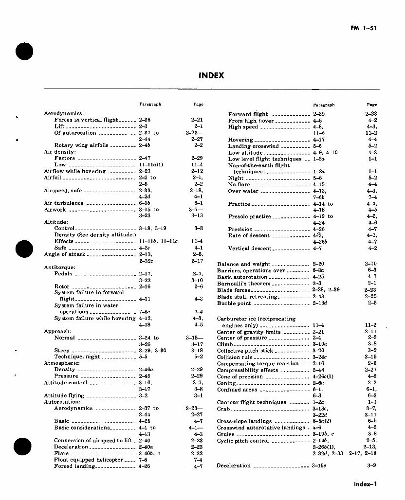
FM 1-51
INDEX
Paragraph Page Paragraph
Aerodynamics: Forces in vertical flight 2-36 Lift 2-3 Of autorotation 2-37 to
2-44 Rotary wing airfoils ^ 2-46
Air density: Factors 2-47 Low ll-lla(l)
Airflow while hovering 2-23 Airfoil 2-2 to
2- 5 Airspeed, safe 2-33,
4-2d Air turbulence 6-16 Airwork 3-15 to
3- 23 Altitude:
Control 3-18, 3-19 Density (See density altitude.) Effects 11-116, 11-llc Safe 4-2e
Angle of attack 2-13,
2-21 2-1
2-23— 2-27 2-2
2- 29 11-4 2-12 2-1, 2-2
2-18, 4-1 6-1
3-7— 3- 13
3- 8
11-4 4- 1 2-5,
Forward flight From high hover .. High speed
Hovering Landing crosswind Low altitude
2-39 4-5 4-8, 11-6 4- 17 5- 6
Low level flight techniques __ l-2a Nap-of-the-earth flight
techniques l-2o Night 5-6 No-flare 4-15 Over water 4-13,
7-66 Practice 4-14 to
4-18 Presolo practice 4-19 to
4-24 Precision 4-26 Rate of descent 4-?!,
4-266 Vertical descent 4-7
Antitorque: Pedals
Rotor System failure in forward
flight System failure in water
2-3 2c
2- 17, 3- 22 2-16
4- 11
2-17
2- 7, 3- 10
2-6
4-3
Balance and weight 2-20 Barriers, operations over 6-3a Basic autorotation 4-25 Bernoulli’s theorem 2-3 Blade forces 2-38, 2-39 Blade stall, retreating 2-43 Burble point 2-13d
operations System failure while hovering
Approach: Normal
7-6c 4-12, 4-18
to
Steep Technique, night.
Atmospheric: Density Pressure
Attitude control
Attitude flying Autorotation:
Aerodynamics
Basic Basic considerations.
Conversion of airspeed to lift. Deceleration Flare Float equipped helicopter Forced landing
3-24 3-26 3-29, 3-30 5-5
2-4 6a 2- 45 3- 16, 3-17 3- 2
2-37 to 2-44 4- 25 4-1 to 4-13 2-40 2-4 0a 2-406, c 7-6 4-26
7—4 4-3, Carburetor ice (reciprocating 4- 5 engines only) 11-4
Center of gravity limits 2-21 3-15— Center of pressure 2-4
3-17 Climb 3-19a 3-18 Collective pitch stick 3-20 5- 2 Collision rule 3-24c
Compensating torque reaction 2-16 2-29 Compressibility effects 2-44 2- 29 Cone of precision 4~26c(l) 3- 7, Coning 2-6a 3-8 Confined areas 6-1, 3- 1 6-3
Contour flight techniques l-2a 2-23— Crab 3-13c,
2-27 3-22d 4- 7 Cross-slope landings 6-5a(2)
4-1— Crosswind autorotative landings . 4-6 4-3 Cruise 3-196, c
2-23 Cyclic pitch control 2-146, 2-23 2-266(1), 2-23 2-32d, 2-33 7-4 4_7 Deceleration 3-19c
2-17,
Page
2-23 4-2 4-3, 11-2 4- 4 5- 2 4- 3 1-1
1-1 5- 2 4-4 4-3, 7-4
4-4, 4-5 4-5, 4-6 4-7 4-1, 4-7 4-2
2-10 6-3 4-7 2-1
2-23 2-25
2-5
11-2 2-11
2-2 3-8 3- 9
3-15 2-6
2- 27 4- 8 2-2
6-1, 6-3 1-1
3- 7, 3-11 6-5 4- 2 3-8 2- 5,
2-13, 2-18
3- 9
Index-1
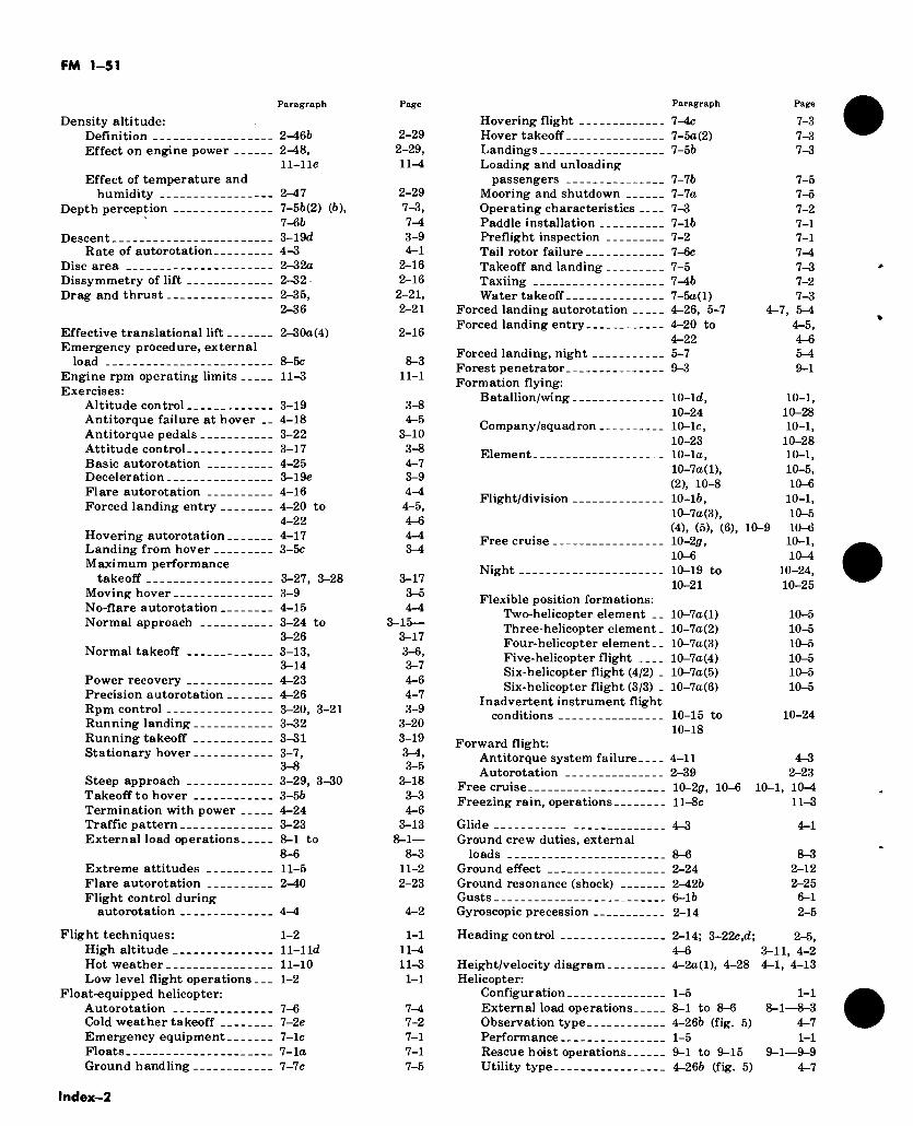
FM 1-51
Paragraph
Density altitude: Definition 2-466 Effect on engine power 2-48,
11-lle Effect of temperature and
humidity 2-47 Depth perception 7-56(2) (6),
7- 66 Descent 3-19d
Rate of autorotation 4-3 Disc area 2-32a Dissymmetry of lift 2-32 ■ Drag and thrust 2-35,
2- 36
Effective translational lift 2-30a(4) Emergency procedure, external
load 8-5c Engine rpm operating limits 11-3 Exercises:
Altitude control 3-19 Antitorque failure at hover __ 4-18 Antitorque pedals 3-22 Attitude control 3-17 Basic autorotation 4-25 Deceleration 3-19e Flare autorotation 4-16 Forced landing entry 4-20 to
4-22 Hovering autorotation 4-17 Landing from hover 3-5c Maximum performance
takeoff 3-27, 3-28 Moving hover 3-9 No-flare autorotation 4-15 Normal approach 3-24 to
3- 26 Normal takeoff 3-13,
3-14 Power recovery 4-23 Precision autorotation 4-26 Rpm control 3-20, 3-21 Running landing 3-32 Running takeoff 3-31 Stationary hover 3-7,
3-8 Steep approach 3-29, 3-30 Takeoff to hover 3-56 Termination with power 4-24 Traffic pattern 3-23 External load operations 8-1 to
8- 6 Extreme attitudes 11-5 Flare autorotation 2-40 Flight control during
autorotation 4-4
Flight techniques: 1-2 High altitude 11-1 Id Hot weather 11-10 Low level flight operations 1-2
Float-equipped helicopter: Autorotation 7-6 Cold weather takeoff 7-2e Emergency equipment 7-lc Floats 7-la Ground handling 7-7c
Page
2-29 2-29, 11-4
2- 29 7-3, 7- 4 3- 9 4- 1
2-16 2-16 2-21, 2-21
2-16
8- 3 11-1
3- 8 4- 5
3- 10 3- 8 4- 7 3- 9 4- 4 4-5, 4-6 4-4 3-4
3-17 3- 5 4- 4
3-15— 3-17 3-6, 3- 7 4- 6 4-7 3-9
3-20 3-19 8-4, 3-5
3-18 3- 3 4- 6
3-13 8-1—
8-3 11-2 2-23
4-2
1-1 11-4 11-3 1-1
7-4 7-2 7-1 7-1 7-5
Paragraph Page
Hovering flight Hover takeoff Landings Loading and unloading
passengers Mooring and shutdown Operating characteristics Paddle installation Preflight inspection Tail rotor failure Takeoff and landing Taxiing Water takeoff
Forced landing autorotation Forced landing entry
Forced landing, night Forest penetrator Formation flying:
Batallion/wing
Company/squadron
Element
Flight/division
Free cruise
Night
7-4c 7-3 7-5a(2) 7-3 7-56 7-3
7-76 7-5 7-7a 7-5 7-3 7-2 7-16 7-1 7-2 7-1 7-6c 7-4 7-5 7-3 7-46 7-2 7-5a(l) 7-3 4-26, 5-7 4-7, 5-4 4-20 to 4-5, 4- 22 4-6 5- 7 5-4 9- 3 9-1
10- ld, 10-1, 10-24 10-28 10-lc, 10-1, 10-23 10-28 10-la, 10-1, 10-7a(l), 10-5, (2), 10-8 10-6 10-16, 10-1, 10-7a(3), 10-5 (4), (5), (6), 10-9 10-6 10-2f/, 10-1, 10-6 10^1 10-19 to 10-24, 10-21 10-25
Flexible position formations: Two-helicopter element __ 10-7a(l) Three-helicopter element _ 10-7a(2) Four-helicopter element.- 10-7a(3) Five-helicopter flight 10-7a(4) Six-helicopter flight (4/2) _ 10-7a(5) Six-helicopter flight (3/3) . 10-7a(6)
Inadvertent instrument flight conditions 10-15 to
10-18 Forward flight:
Antitorque system failure 4-11 Autorotation 2-39
Free cruise 10-2p, 10-6 Freezing rain, operations ll-8c
10-5 10-5 10-5 10-5 10-5 10-5
10-24
4-3 2-23
10-1, 10^1 11-3
Glide 4-3 Ground crew duties, external
loads 8-6 Ground effect 2-24 Ground resonance (shock) 2-426 Gusts 6-16 Gyroscopic precession 2-14
4-1
8-3 2-12 2-25
6-1 2-5
Heading control
Height/velocity diagram Helicopter:
Configuration External load operations. Observation type Performance Rescue hoist operations.. Utility type
2-14; 3-22c,d; 2-5, 4-6 3-11, 4-2 4-2a(l), 4-28 4-1, 4-13
1-5 1-1 8— 1 to 8—6 8—1—8—3 4-266 (fig. 5) 4-7 1-5 1-1 9- 1 to 9-15 9-1—9-9 4-266 (fig. 5) 4-7
lndex-2
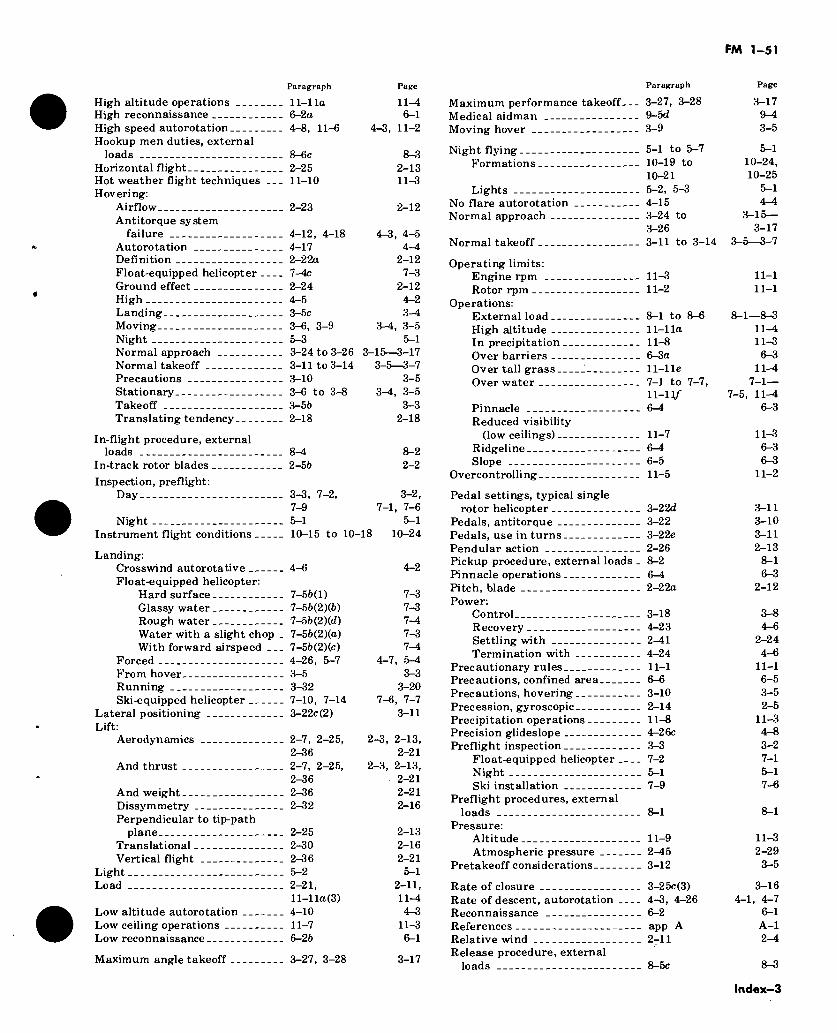
FM 1-51
Paragraph Page
High altitude operations 11-1 la High reconnaissance 6-2a High speed autorotation 4-8, 11-6 Hookup men duties, external
loads 8-6c Horizontal flight 2-25 Hot weather flight techniques 11-10 Hovering:
Airflow 2-23 Antitorque system
failure 4-12, 4-18 Autorotation 4-17 Definition 2-22a
11-4 6-1
4-3, 11-2
8-3 2-13 11-3
2-12
4-3, 4-5 4-4
2-12 Float-equipped helicopter 7-4c 7-3 Ground effect High Landing Moving Night Normal approach Normal takeoff Precautions Stationary Takeoff Translating tendency
2- 24 4- 5 3- 5c 3-6, 3-9 5- 3 3-24 to 3-26 3-11 to 3-14 3-10 3—6 to 3—8 3-56 2-18
2-12 4- 2 3-4
3-4, 3-5 5- 1
3-15—3-17 3-5—3-7
3-5 3-4, 3-5
3-3 2-18
In-flight procedure, external loads 8-4 8-2
In-track rotor blades 2-56 2-2
Inspection, preflight: Day 3-3, 7-2, 3-2,
7-9 7-1, 7-6 Night 5-1 5-1
Instrument flight conditions 10-15 to 10-18 10-24
Landing: Crosswind autorotative 4-6 Float-equipped helicopter:
Hard surface 7-56(1) Glassy water 7-56(2)(6) Rough water 7-56(2)(d) Water with a slight chop _ 7-56(2)(a) With forward airspeed 7-56(2)(c)
Forced 4-26, 5-7 From hover 3-5 Running 3-32 Ski-equipped helicopter 7-10, 7-14
Lateral positioning 3-22c(2) Lift:
Aerodynamics 2-7, 2-25, 2-36
And thrust 2-7, 2-25, 2-36
And weight 2-36 Dissymmetry 2-32 Perpendicular to tip-path
plane 2-25 Translational 2-30 Vertical flight 2-36
Light 5-2 Load 2-21,
11-1 la (3) Low altitude autorotation 4-10 Low ceiling operations 11-7 Low reconnaissance 6-26
4-2
7-3 7-3 7-4 7-3 7-4
4-7, 5-4 3-3
3-20 7-6, 7-7
3-11
2-3, 2-13, 2-21
2-3, 2-13, 2-21 2-21 2-16
2-13 2-16 2-21 5- 1
2-11, 11-4 4-3
11-3 6- 1
Maximum angle takeoff 3-27, 3-28 3-17
Paragraph Page
Maximum performance takeoff— 3-27, 3-28 3-17 Medical aidman 9-5d 9-4 Moving hover 3-9 3-5
Night flying 5-1 to 5-7 5-1 Formations 10-19 to 10-24,
10-21 10-25 Lights 5-2, 5-3 5-1
No flare autorotation 4-15 4—4 Normal approach 3-24 to 3-15—
3-26 3-17 Normal takeoff 3-11 to 3-14 3-5—3-7
Operating limits: Engine rpm 11-3 11-1 Rotor rpm 11-2 11-1
Operations: External load 8-1 to 8-6 8-1—8-3 High altitude 11-1 la 11—4 In precipitation 11-8 11-3 Over barriers 6-3a 6—3 Over tall grass ' 11-lle 11-4 Over water 7-1 to 7-7, 7-1—
11-H/- 7-5, 11^1 Pinnacle 6-4 6-3 Reduced visibility
(low ceilings) 11-7 11-3 Ridgeline 6—4 6-3 Slope 6-5 6-3
Overcontrolling 11-5 11-2
Pedal settings, typical single rotor helicopter 3-22d 3-11
Pedals, antitorque 3-22 3-10 Pedals, use in turns 3-22e 3-11 Pendular action 2-26 2-13 Pickup procedure, external loads _ 8-2 8-1 Pinnacle operations 6-4 6-3 Pitch, blade 2-22a 2-12 Power:
Control 3-18 3-8 Recovery 4-23 4-6 Settling with 2-41 2-24 Termination with 4-24 4-6
Precautionary rules 11-1 11-1 Precautions, confined area 6-6 6-5 Precautions, hovering 3-10 3-5 Precession, gyroscopic 2-14 2-5 Precipitation operations 11-8 11-3 Precision glideslope 4-26c 4-8 Preflight inspection 3-3 3-2
Float-equipped helicopter 7-2 7-1 Night 5-1 5-1 Ski installation 7-9 7-6
Preflight procedures, external loads 8-1 8-1
Pressure: Altitude 11-9 11-3 Atmospheric pressure 2-45 2-29
Pretakeoff considerations 3-12 3-5
Rate of closure 3-25c(3) 3-16 Rate of descent, autorotation 4-3, 4-26 4-1, 4-7 Reconnaissance 6-2 6-1 References app A A-l Relative wind 2^11 2-4 Release procedure, external
loads 8-5c 8-3
Index—3
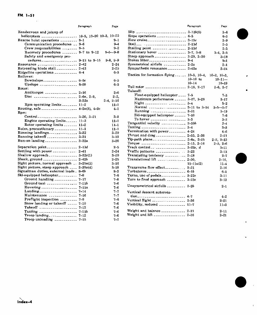
FM 1-51
Paragraph Page
Rendezvous and joinup of helicopters 10-5, 10-20 10-3, 10-25
Rescue hoist operations 9-1 9-1 Communication procedures -- 9-6 9—4 Crew responsibilities 9-5 9-2 Recovery procedures 9-7 to 9-12 9-5—9-8 Safety and emergency pro-
cedures 9-13 to 9-15 9-8, 9-9 Resonance 2-42 2-24 Retreating blade stall 2-43 2-25 Ridgeline operations 6—4 6-3 Rollover:
Downslope 6-5c 6-5 Upslope 6-56 6-5
Rotor: Antitorque Disc
Rpm operating limits __ Routing, safe Rpm:
Control Engine operating limits Rotor operating limits _
Rules, precautionary Running landings Running takeoff Run-on landing
2-16 2-6 2-6a, 2-9, 2-2, 2-32a 2-4, 2-16 11-2 11-1 4-2a(3), 4-2c 4-1
3-20, 3-21 3-9 11-3 11-1 11-2 11-1 11-1 11-1 3-32 3-20 3-31 3-19 3-32a 3-20
Separation point 2-13d Settling with power 2-41 Shallow approach 3-32c(l) Shock, ground 2—426 Sight picture, normal approach __ 3-25a(5) Sight picture, steep approach 3-30a(4) Signalman duties, external loads _ 8-66 Ski-equipped helicopter 7-8
Ground handling 7-17 Ground taxi 7-116 Hovering 7-lla Landing 7-14 Maintenance 7-16 Preflight inspection 7-9 Snow landing or takeoff 7-10 Takeoff 7-13 Taxiing 7-116 Troop landing 7-12 Troop unloading 7-15
2-5 2- 24 3- 20 2- 25 3- 16 3-18 8-3 7-6 7-8 7-6 7-6 7-7 7-7 7-6 7-6 7-6 7-6 7-6 7-7
Paragraph
Slip 3-136(6) Slope operations 6-5 Slow cruise 3-19c Stall 2-13d Stalling point 2-13d Stationary hover 3-7, 3-8 Steep approach 3-29, 3-30 Stokes litter 9-4 Symmetrical airfoils 2-2a Sympathetic resonance 2-42a
Tactics for formation flying 10-3, 10-4, 10-10 to 10- 14
Tail rotor 2-16, 2-17 Takeoff:
Float-equipped helicopter 7-5 Maximum performance 3-27, 3-28 Night 5-4 Normal 3-11 to 3-14 Running 3-31 Ski-equipped helicopter 7-10 To hover 3-5
Tangential velocity 2-106 Taxiing 3—1 Termination with power 4-24 Thrust and drag 2-35, 2-36 Tip-path plane 2-6a, 2-25 Torque 2-15, 2-16 Track control 3-22c, d Traffic patterns 3-23 Translating tendency 2-18 Translational lift 2-30,
11- 1 la (2) Transverse flow effect 2-31 Turbulence 6-16 Turns, use of pedals 3-22e Turn to final approach 3-23e
Unsymmetrical airfoils 2-26
Vertical descent autorota- tion 4-7
Vertical flight 2-36 Visibility, reduced 11-7
Weight and balance 2-21 Weight and lift 2-36
Page
3-6 6- 3 3-9 2-5 2- 5
3—4, 3-5 3-18
9-1 2-1
2- 24
10-2, 10-3, 10-11—
10-19 2- 6, 2-7
7- 3 3- 17 5- 2
3- 5—3-7 3-19
7-6 3- 3 2- 4 3- 3 4- 6
2-21 2-2, 2-13
2-5, 2-6 3-11 3-13
2-7 2-16, 11-4 2-16
6- 1 3-11 3-13
2-1
4-2 2-21 11-3
2-11 2-21
\ Index-4
FM 1-51
By Order of the Secretary of the Army:
CREIGHTON W. ABRAMS General, United States Army
Official: Chief of Staff VERNE L. BOWERS Major General, United States Army The Adjutant General
DISTRIBUTION:
Active Army, ARNG, USAR: To be distributed in accordance with DA Form 12-31, Section I require- ments for Operator and Crew for All Rotor Wing Aircraft (Qty rqr block no. 77).
aU.S. GOVERNMENT PRINTING OFFICE: 1974—549-855/14A


RECOMMENDED CHANGES TO PUBLICATIONS
TOt (Forward to proponent oi publication) (Include ZIP Code)
Commandant, US Army Aviation School ATTN: ATST-CTD-D Fort Rucker, Alabama 36360
FROMi (Activity and location) (Include ZIP Code)
SECTION A . ALL PUBLICATIONS EXCEPT RPSTL AND SC/SM PUBLICATION NUMBER
FM 1-51 DATE
April 1974 TITLE
Rotary Wing Flight ITEM NO.
PAGE NO.
PARA. GRAIPH.
UNE NO. •
FIGURE NO.
TABLE NO.
RECOMMENDED CHANGES AND REASON (Exact wording oi recommended change muet be given)
* Reference to line numbers within the paragraph or subparagraph.
SECTION B - REMARKS (Any genera/ remarks or recommendations lor improvement of publications)
TYPED NAME, GRADE. OR TITLE AND TELEPHONE NUMBER SIGNATURE
DA ^“-,2028-W.,;
DEPARTMENT OP THE ARMY POSTASE ANO FEES PAID
DEPARTMENT OF THE ARMY
DoD-314
OFFICIAL BUSINESS PENALTY FOR PRIVATE USE, $300
r
US.MAIL
Commandant
United States Army Aviation School ATTN: ATST-CTD-D Fort Rucker, Alabama 36360
Fold hare - then lasten at top
j«ci<ET .0 549 -8 55 ¡g® M.
Width -, Depth . A? I I Sq. Ht. JJ^line | | Brood | | Patter
□ Duo Tone □ Rescreen
Add'l. Info.-
(mais) %
RECOMMENDED CHANGES TO PUBLICATIONS
TO: (Forward to proponent oi publication) (Include ZIP Code)
Commandant, US Army Aviation School ATTN: ATST-CTD-D Fort Rucker, Alabama 36360
FROM: (Ac tivity and location) (Include ZIP Code)
SECTION A - ALL PUBLICATIONS EXCEPT RPSTL AND SC/SM PUBLICATION NUMBER
FM 1-51 April 1974 TITLE
Rotary Wing Flight ITEM NO.
PAGE NO.
PARA- GRAIPH.
LINE NO. •
FIGURE NO.
TABLE NO.
RECOMMENDED CHANGES AND REASON (Exact wording of recommended change muet be given)
* Reference to line numbers within the paragraph or subparagraph.
SECTION B - REMARKS (Any general remarks or recommendations lor improvement of publications)
TYPED NAME. GRADE. OR TITLE AND TELEPHONE NUMBER SIGNATURE
DA -".“„2028-W,
DEPARTMENT OF THE ARMY POSTAGE AND FEES PAID
DEPARTMENT OF THE ARMY
DoD-314
OFFICIAL BUSINESS PENALTY FOR PRIVATE USE. $300
Commandant United States Army Aviation School ATTN: ATST-CTD-D Fort Rucker, Alabama 36360
Fold here - then fasten at top
RECOMMENDED CHANGES TO PUBLICATIONS
ro¡ (Forward to proponent of publication) (Include ZIP Code) FROM: (Activity and location) (Include
Commandant, US Army Aviation School ATTN: ATST-CTD-D Fort Rucker, Alabama 36360
SECTION A ■ ALL PUBLICATIONS EXCEPT RPSTL AND SC/SM PUBLICATION NUMBER DATE TITLE
FM 1-51 April 1974 Rotary Wing Flight
ZIP Code)
ITEM
NO.
PAGE
NO.
PARA.
GRAPH-
LINE FIGURE
NO. * NO.
TABLE
NO. RECOMMENDED CHANGES AND REASON
(Exact wording of re commended change muet be given)
• Reference to tine numbere within the paragraph or subparagraph.
SECTION B - REMARKS (Any general remarks or recommendations for improvement of publications)
TYPED NAME. GRADE. OR TITLE AND TELEPHONE NUMBER SIGNATURE
DA ^".2028-W.o
DEPARTMENT OF THE ARMY POSTASE AND FEES PAID
DEPARTMENT OF THE ARMY
DoD-314
OFFICIAL BUSINESS
PENALTY FOR PRIVATE USE, $300
Commandant United States Army Aviation School ATTN: ATST-CTD-D Fort Rucker, Alabama 36360
Fold here - then fasten at top
RECOMMENDED CHANGES TO PUBLICATIONS
TO: (Forward to proponent oí pubtication) (Include ZIP Coda)
Commandant, US Army Aviation School ATTN: ATST-CTD-D Fort Rucker, Alabama 36360
FROM: (Activity and location) (Include ZIP Code)
SECTION A . ALL PUBLICATIONS EXCEPT RPSTL AND SC/SM
PUBLICATION NUMBER
FM 1-51 DATE
April 1974 TITLE
Rotary Wing Flight ITEM NO.
PAGE NO.
PAR| GR
RA- AiPH.
LINE NO. •
FIGURE NO.
TABLE NO.
RECOMMENDED CHANGES AND REASON (Exact wording oí recommended chango muet be given)
» Reference to tine numbers within the paragraph or subparagraph.
SECTION B * REMARKS (Any general remarks or recommendations for improvemenf oí pubticationa)
TYPED NAME. GRADE. OR TITLE AND TELEPHONE NUMBER SIGNATURE
DA S8W.2028-W,
DEPARTMENT OF THE ARMY POSTAGE AND FEES PAID
DEPARTMENT OF THE ARMY
DoD-314
OFFICIAL BUSINESS PENALTY FOR PRIVATE USE. $300
(SI sssag
Commandant
United States Army Aviation School ATTN: ATST-CTD-D Fort Rucker, Alabama 36360
l Fotd here - then lasten at top
RECOMMENDED CHANGES TO PUBLICATIONS
TOî (Forward to proponent oi publication) (Include ZIP Code)
Commandant, US Army Aviation School ATTN: ATST-CTD-D Fort Rucker, Alabama 36360
FROM: (Activity and location) (Include ZIP Code)
SECTION A ■ ALL PUBLICATIONS EXCEPT RPSTL AND SC/SM PUBLICATION NUMBER
FM 1-51 April 1974 Rotary Wing Flight ITEM NO.
PAGE NO.
PARA- GRAlPH-
LINE NO. •
FIGURE NO.
TABLE NO.
RECOMMENDED CHANGES AND REASON (Exact wording of recommended change must be given)
* Reference to Une numbers within the paragraph or subparagraph.
SECTION B - REMARKS (Any genera/ remarks or recommendations for improvement oi publicatione)
TYPED NAME. GRADE. OR TITLE AND TELEPHONE NUMBER SIGNATURE
DA ■ "8?“>2028-lrr.,,j
DEPARTMENT OF THE ARMY
OFFICIAL BUSINESS PENALTY FOR PRIVATE USE, $300
0001140520 POSTAGE AND FEES PAID
DEPARTMENT OF THE ARMY
DoD-314
r
UL&MAIL
Commandant United States Army Aviation School ATTN: ATST-CTD-D Fort Rucker, Alabama 36360
Foïd here - then fasten at top
i *
0001
1405
20


![RAIL-AERODYNAMICS 2018Rail-Aerodynamics 2018: Infrastructure and rolling stock ... Aerodynamics and Thermodynamics] High-Speed Particle Image Velocimetry for Near-ground Boundary Layer](https://img.pdfslide.net/doc/110x75/5f061cd47e708231d4165a5b/rail-aerodynamics-2018-rail-aerodynamics-2018-infrastructure-and-rolling-stock.jpg)