Embed Size (px)
Citation preview
CAD drawing data catalogis available.
422
VALVES GENERAL CATALOG
INDEX
FM-SOLID MANIFOLDseries
Before use, be sure to read the “Safety Precautions” on p. 31.Caution
FM-S
OLID
MAN
IFOL
D X8
8M S
ERIE
S
Features 423Module Configuration Outline 424Module Configuration 425Examples of FM-SOLID MANIFOLD X88M Configuration 427Module Mass and Dimensions 432Manifold Order Codes 433Precautions for System Configuration 436Module Order Codes 437Wiring Modules 441
Details of Wiring Specifications 442Detailed Diagram of Solenoid Wiring System 443Dimensions 445
Serial Transmission Modules 448Dimensions 449
Compact Serial Transmission System 450Piping Modules 454
Dimensions 455Air Preparation Modules 457
Dimensions 458Valve Modules 460
Cylinder Operating Speed 464Flow Rate 465Dimensions 466
Ejector Modules 476Dimensions 477
Block-off Plate Modules 481Dimensions 481
End Blocks 483Dimensions 484
Handling Instructions and Precautions 485Important Precautions 494
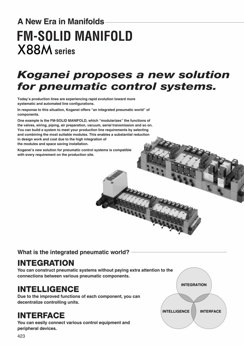
A New Era in Manifolds
Koganei proposes a new solutionfor pneumatic control systems.Today’s production lines are experiencing rapid evolution toward moresystematic and automated line configurations.
In response to this situation, Koganei offers “an integrated pneumatic world” ofcomponents.
One example is the FM-SOLID MANIFOLD, which “modularizes” the functions ofthe valves, wiring, piping, air preparation, vacuum, serial transmission and so on.You can build a system to meet your production line requirements by selectingand combining the most suitable modules. This enables a substantial reductionin design work and cost due to the high integration of the modules and space saving installation.
Koganei’s new solution for pneumatic control systems is compatible with every requirement on the production site.
What is the integrated pneumatic world?
INTEGRATIONYou can construct pneumatic systems without paying extra attention to theconnections between various pneumatic components.
INTELLIGENCEDue to the improved functions of each component, you can decentralize controlling units.
INTERFACEYou can easily connect various control equipment and peripheral devices.
INTELLIGENCE INTERFACE
INTEGRATION
423
series
FM-SOLID MANIFOLD
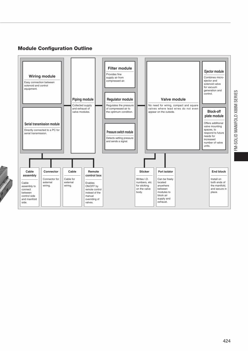
Module Configuration Outline
Cableassembly
Cableassembly toconnectbetweencontrol sideand manifoldside.
Connector
Connector forexternalwiring.
Cable
Cable forexternalwiring.
Remotecontrol box
Enables ON/OFF byremote controlinstead of themanualoverriding ofvalves.
Sticker
Writes I.D.numbers, etc.for stickingon the valvebody.
Port isolator
Can be freelylocatedanywherebetweenmodules toblock airsupply andexhaust.
End block
Install onboth ends ofthe manifold,and secure inplace.
Piping moduleCollected supplyand exhaust ofvalve modules.
Wiring moduleEasy connection betweensolenoid and controlequipment.
Filter moduleProvides fine supply air fromcompressed air.
Regulator moduleRegulates the pressureof compressed air to the optimum condition.
Pressure switch moduleDetects setting pressureand sends a signal.
Serial transmission moduleDirectly connected to a PC forserial transmission.
Ejector moduleCombines micro-ejector andsolenoid valvefor vacuumgeneration andcontrol.
Block-offplate module
Offers additionalvalve mountingspaces, torespond to futureneeds forincreasednumber of valveunits.
Valve moduleNo need for wiring, compact and squarevalves where lead wires do not evenappear on the outside.
FM-S
OLID
MAN
IFOL
D X8
8M S
ERIE
S
424

Module Configuration
Built-in quick fitting typeFlat cable connector type
Wiring modules, p.441Piping modules,
p.454Air preparationmodules, p.457
Serial transmission modules, p.448
D-sub connector type
D-sub connector, side connectionspecification (both R and L mounting)
Wiring bushing connectiontype (right side type)
Wiring bushing connectiontype (lower right side type)
Wiring bushing connectiontype (left side type)
Wiring bushing connectiontype (lower left side type)
For OMRON PCsFor Fuji Electric FAComponents & Systems PCsFor Mitsubishi Electric PCs
For SHARP PCs For Hitachi PCs For Matsushita ElectricWorks PCs
Terminal block type
Filter module
Regulator module
Pressure switch module
With built-in muffler
P port female thread type
With built-in muffler
All port female thread type
All port female thread type,side piping specification
Electronic type
Mechanical type
Cable assembly,p.1039
Connector, p.1040
Cable, p.1040 Remote control box,p.1041
Compact serial transmission system, p.450
For OMRONCompoBus/D
For OMRONSYSBUS Wire System
For OMRONCompoBus/S
For OMRONB7A Link Terminal
For Mitsubishi ElectricMELSECNET/MINI-S3
For Mitsubishi ElectricMELSEC I/O LINK
For Mitsubishi ElectricCC-Link
For Fuji Electric FA Components & SystemsT Link Mini
For NKE, KURODA PRECISION INDUSTRIESUNI-WIRE® System
For SUNXS-LINK
For KEYENCEKZ-R
For KOYO ELECTRONICS INDUSTRIESSA Bus
※UNI-WIRE® System is a serial parallel trans-mission system developed jointly by NKE andKURODA PRECISION INDUSTRIES.
425
seriesFM-SOLID MANIFOLD
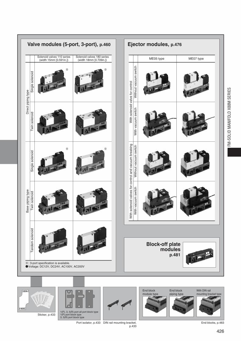
Valve modules (5-port, 3-port), p.460 Ejector modules, p.476
Block-off platemodules
p.481
Solenoid valves 110 series(width 15mm [0.591in.])
Solenoid valves 180 series(width 18mm [0.709in.])
※ ※
※ ※
Dire
ctpi
ping
type
Bas
epi
ping
type
ME05 type ME07 type
※: 3-port specification is available.Voltage: DC12V, DC24V, AC100V, AC200V
Sticker, p.433
Port isolator, p.433 DIN rail mounting bracket,p.433
End block module type
End block piping type
With DIN rail mounting bracket type
End blocks, p.483
1(P), 3, 5(R) port all port block type1(P) port block type3, 5(R) port block type
コガネイ
コガネイ
426
FM-S
OLID
MAN
IFOL
D X8
8M S
ERIE
S
Sin
gle
sole
noid
Tan
dem
sole
noid
Tw
inso
leno
idS
ingl
eso
leno
idT
win
sole
noid
With
outv
acuu
msw
itch
With
vacu
umsw
itch
With
outv
acuu
msw
itch
With
vacu
umsw
itch
With
sole
noid
valv
efo
rco
ntro
lW
ithso
leno
idva
lves
for
cont
rola
ndva
cuum
brea
king
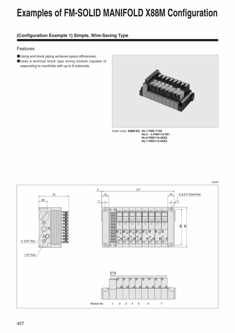
(Configuration Example 1) Simple, Wire-Saving Type
Features
Using end block piping achieves space efficiencies.
Uses a terminal block type wiring module capable ofresponding to manifolds with up to 8 solenoids.
Order code: X88M-ED No.1-FMC-T100No.2~5-FMX110-4E1No.6-FMX110-4KE2No.7-FMX113-4KE2
R
P
4(A)4(A)4(A)4(A)4(A)4(A)
2(B)2(B)2(B)2(B)2(B)2(B)
75
20
3, 5(R)Port
1(P)Port
4
7 7
177
15 15 4-φ4.3(Oval hole)
88 98
Module No. 21 3 4 5 6 7
Examples of FM-SOLID MANIFOLD X88M Configuration
427
(mm)

(Configuration Example 2) 110, 180 and Ejector Combination Mounting Type
Features
Collective wiring for operation signals ofvalves (110 and 180) and ejectors.
Using port isolators for the air supply/exhaust between the valves and ejectors,makes individual air supply/exhaustpossible, and ensures steady operationsof the ejector.The vacuum switch sensor signal can be
extracted individually.
Order code: X88M No.1-FMC-F200No.2~5-FMW110-4E1-J4SNo.6-FMP-FJ10LNo.7-FMB-A (port isolator)No.8~11-FMW180-4E1-J6SNo.12-FMP-FJ10LNo.13-FMB-A (port isolator)No.14-FMJ05E2-J4S-ENo.15-FMJ07E1-J6S-ENo.16-FMP-FJ10L
R
P
-+
85.3
20
15 19 16
7
329
32 19 16 15
7
60
984.
5
88
26
Module No.
1(P)Port
2(B)Port
4(A)Port
21 3 4 5 6 7 8 9 10 11 12 13 14 15 16
4-φ4.3(Oval hole)
SW. SW.
110 180
Portisolator
Portisolator
Location of port isolators
428
(mm)
FM-S
OLID
MAN
IFOL
D X8
8M S
ERIE
S
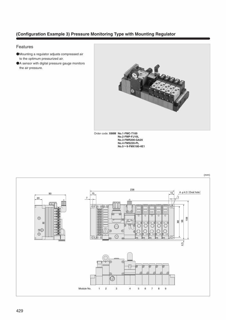
(Configuration Example 3) Pressure Monitoring Type with Mounting Regulator
Features
Mounting a regulator adjusts compressed airto the optimum pressurized air.
A sensor with digital pressure gauge monitorsthe air pressure.
Order code: X88M No.1-FMC-T100No.2-FMP-FJ10LNo.3-FMR200-GA20No.4-FMS220-PLNo.5~~9-FMX180-4E1
R
P
4(A)
2(B) 2(B) 2(B) 2(B) 2(B)
4(A) 4(A) 4(A) 4(A)0
90
20 7
15
23815
7
4-φ4.3(Oval hole)
4.5
9888
108
Module No. 21 3 4 5 6 7 8 9
429
(mm)
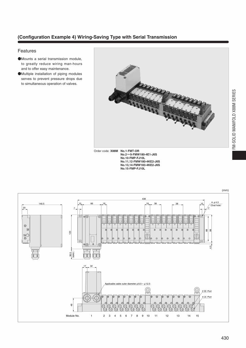
(Configuration Example 4) Wiring-Saving Type with Serial Transmission
Features
Mounts a serial transmission module,to greatly reduce wiring man-hoursand to offer easy maintenance.
Multiple installation of piping modulesserves to prevent pressure drops dueto simultaneous operation of valves.
Order code: X88M No.1-FMT-ORNo.2~~9-FMW180-4E1-J6SNo.10-FMP-FJ10LNo.11,12-FMW180-4KE2-J6SNo.13,14-FMW183-4KE2-J6SNo.15-FMP-FJ10L
RP
48
Applicable cable outer diameterφ8.5~φ12.5
17 32
Module No. 1 2 3 4 5 6 7 8 9 10 11 12 13 14 15
36.5
(M
AX
.)
120
7
15 66 19
7
4-φ4.3(Oval hole)
15383819
438
9888
4.5
140.5
20
2(B)Port
4(A)Port
430
(mm)
FM-S
OLID
MAN
IFOL
D X8
8M S
ERIE
S

(Configuration Example 5) Dual-use Type for Parallel and Serial Transmission
(Configuration Example 6) Wiring Branch Type for Operating Other Valves, Relays, etc.
Features
Uses the same manifold to conform toeither parallel transmission or serialtransmission.
Installs 0.7W specification valves (as aspecial order).
Mounting onto a DIN rail simplif iesmounting of remote I/O stations andother equipment.
Precautions for making order
For the wiring module, select FMC-F201.
The solenoid valve for the manifoldshould be a low current specification ofDC24V (0.7W with LED). Specify thevalve module type by adding “-001W.”However, “-001W” is not required for the
tandem solenoid valve (FMY).
Purchase both the cable type G79- andtransmission terminal type G-71-OD16(DC24V) from OMRON separately.
FeaturesBranching the serial transmission
module’s 16 operating signals to theoutside of the manifold enables theoperations of other devices to achievethe effective use of contact points.
Can also operate devices by using theparallel transmission module.
Wiring modules on the branch side can also be selected.
Precautions for making orderA wiring branch manifold requires a
special order. Consult us.
For external devices, purchaseMatsushita Electric Works’ relay (PCrelay terminal AY112402, etc.), orOMRON’s relay terminal (I/O relayterminal G7TC-OC08, etc.).
Order code: X88M-DN No.1-FMC-F201No.2~17-FMW110-4E1-J4S-001WNo.18-FMP-FR02
Order code: X88M-DN No.1-FMT-No.2-FMC-FJ10LNo.3~11-FMW180-4E1-J6SNo.12-FMC-F201-13W
431
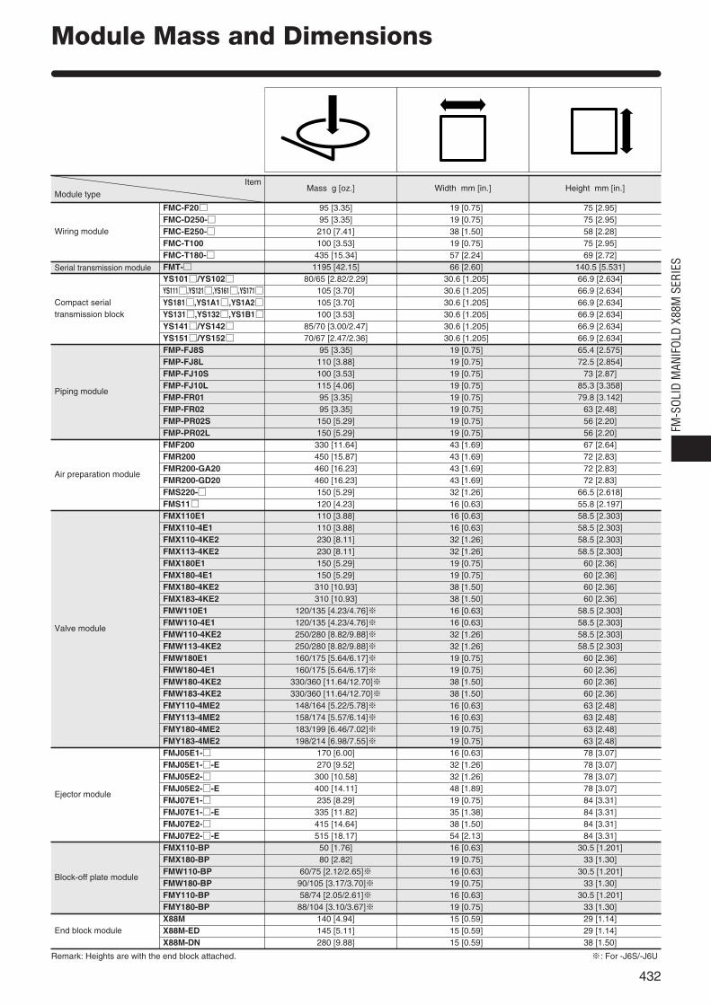
Module Mass and Dimensions
Wiring module
Serial transmission module
Piping module
Compact serialtransmission block
Air preparation module
Valve module
Ejector module
Block-off plate module
End block module
FMC-F20 95 [3.35] 19 [0.75] 75 [2.95]FMC-D250- 95 [3.35] 19 [0.75] 75 [2.95]FMC-E250- 210 [7.41] 38 [1.50] 58 [2.28]FMC-T100 100 [3.53] 19 [0.75] 75 [2.95]FMC-T180- 435 [15.34] 57 [2.24] 69 [2.72]FMT- 1195 [42.15] 66 [2.60] 140.5 [5.531]YS101/YS102 80/65 [2.82/2.29] 30.6 [1.205] 66.9 [2.634]YS111,YS121,YS161,YS171 105 [3.70] 30.6 [1.205] 66.9 [2.634]YS181,YS1A1,YS1A2 105 [3.70] 30.6 [1.205] 66.9 [2.634]YS131,YS132,YS1B1 100 [3.53] 30.6 [1.205] 66.9 [2.634]YS141/YS142 85/70 [3.00/2.47] 30.6 [1.205] 66.9 [2.634]YS151/YS152 70/67 [2.47/2.36] 30.6 [1.205] 66.9 [2.634]FMP-FJ8S 95 [3.35] 19 [0.75] 65.4 [2.575]FMP-FJ8L 110 [3.88] 19 [0.75] 72.5 [2.854]FMP-FJ10S 100 [3.53] 19 [0.75] 73 [2.87]FMP-FJ10L 115 [4.06] 19 [0.75] 85.3 [3.358]FMP-FR01 95 [3.35] 19 [0.75] 79.8 [3.142]FMP-FR02 95 [3.35] 19 [0.75] 63 [2.48]FMP-PR02S 150 [5.29] 19 [0.75] 56 [2.20]FMP-PR02L 150 [5.29] 19 [0.75] 56 [2.20]FMF200 330 [11.64] 43 [1.69] 67 [2.64]FMR200 450 [15.87] 43 [1.69] 72 [2.83]FMR200-GA20 460 [16.23] 43 [1.69] 72 [2.83]FMR200-GD20 460 [16.23] 43 [1.69] 72 [2.83]FMS220- 150 [5.29] 32 [1.26] 66.5 [2.618]FMS11 120 [4.23] 16 [0.63] 55.8 [2.197]FMX110E1 110 [3.88] 16 [0.63] 58.5 [2.303]FMX110-4E1 110 [3.88] 16 [0.63] 58.5 [2.303]FMX110-4KE2 230 [8.11] 32 [1.26] 58.5 [2.303]FMX113-4KE2 230 [8.11] 32 [1.26] 58.5 [2.303]FMX180E1 150 [5.29] 19 [0.75] 60 [2.36]FMX180-4E1 150 [5.29] 19 [0.75] 60 [2.36]FMX180-4KE2 310 [10.93] 38 [1.50] 60 [2.36]FMX183-4KE2 310 [10.93] 38 [1.50] 60 [2.36]FMW110E1 120/135 [4.23/4.76]※ 16 [0.63] 58.5 [2.303]FMW110-4E1 120/135 [4.23/4.76]※ 16 [0.63] 58.5 [2.303]FMW110-4KE2 250/280 [8.82/9.88]※ 32 [1.26] 58.5 [2.303]FMW113-4KE2 250/280 [8.82/9.88]※ 32 [1.26] 58.5 [2.303]FMW180E1 160/175 [5.64/6.17]※ 19 [0.75] 60 [2.36]FMW180-4E1 160/175 [5.64/6.17]※ 19 [0.75] 60 [2.36]FMW180-4KE2 330/360 [11.64/12.70]※ 38 [1.50] 60 [2.36]FMW183-4KE2 330/360 [11.64/12.70]※ 38 [1.50] 60 [2.36]FMY110-4ME2 148/164 [5.22/5.78]※ 16 [0.63] 63 [2.48]FMY113-4ME2 158/174 [5.57/6.14]※ 16 [0.63] 63 [2.48]FMY180-4ME2 183/199 [6.46/7.02]※ 19 [0.75] 63 [2.48]FMY183-4ME2 198/214 [6.98/7.55]※ 19 [0.75] 63 [2.48]FMJ05E1- 170 [6.00] 16 [0.63] 78 [3.07]FMJ05E1--E 270 [9.52] 32 [1.26] 78 [3.07]FMJ05E2- 300 [10.58] 32 [1.26] 78 [3.07]FMJ05E2--E 400 [14.11] 48 [1.89] 78 [3.07]FMJ07E1- 235 [8.29] 19 [0.75] 84 [3.31]FMJ07E1--E 335 [11.82] 35 [1.38] 84 [3.31]FMJ07E2- 415 [14.64] 38 [1.50] 84 [3.31]FMJ07E2--E 515 [18.17] 54 [2.13] 84 [3.31]FMX110-BP 50 [1.76] 16 [0.63] 30.5 [1.201]FMX180-BP 80 [2.82] 19 [0.75] 33 [1.30]FMW110-BP 60/75 [2.12/2.65]※ 16 [0.63] 30.5 [1.201]FMW180-BP 90/105 [3.17/3.70]※ 19 [0.75] 33 [1.30]FMY110-BP 58/74 [2.05/2.61]※ 16 [0.63] 30.5 [1.201]FMY180-BP 88/104 [3.10/3.67]※ 19 [0.75] 33 [1.30]X88M 140 [4.94] 15 [0.59] 29 [1.14]X88M-ED 145 [5.11] 15 [0.59] 29 [1.14]X88M-DN 280 [9.88] 15 [0.59] 38 [1.50]
Item
Module typeMass g [oz.] Width mm [in.] Height mm [in.]
Remark: Heights are with the end block attached. ※: For -J6S/-J6U
432
FM-S
OLID
MAN
IFOL
D X8
8M S
ERIE
S

Manifold Order Codes
FM-SOLID MANIFOLD X88M Series Basic Specifications
Order Codes
Item X88M
Media Air
Operating pressure range MPa kgf/cm2 [psi.] 0.15~0.7 1.5~7.1 [22~102]
Proof pressure MPa kgf/cm2 [psi.] 1.05 10.7 [152]
Operating temperature range°C [°F] 5~50 [41~122]
(atmosphere and media)
Wiring typeCollective wiring type with wiring module
(Flat cable connector type, D-sub connector type, Terminal block type)
End block End block module type/End block piping type
Manifold mounting type Direct mounting type/DIN rail mounting type
Common terminal wiring Positive common/Negative common
Manifold basic modelEnd block type
-ED
Mounting type
-DN
Common terminal wiring
-CM No.1 FMC-F200…
No.2… …
FMJ05E1…
No.n FMX110-4E1…Select from the wiring modules,
piping modules, air preparationmodules, valve modules, orejector modules. One sticker is provided for each
manifold.When combining 2 or more
terminal block type wiringmodules (FMC-T100) side byside, the wiring space for eachterminal block becomes tight.Depending on the wiring typesand condit ions, each wiringgroup’s crimped terminals orlead wires could interfere withother terminal blocks, and itcould be difficult to achieve anorderly wiring. When usingmultiple wiring modules,therefore, carefully study thedesignated locations of eachmodule to ensure that they donot come in contact with eachother. In addition, if the totalnumber using I/O requires 9 to16 terminals, we recommendusing the wiring module typewith wiring bushing connectionspecifications (FMC-T180).
Module No. Module model
End blockmounting type
Blank
Positive common
With DIN railmounting bracket type
-DN
End blockmodule type (1 set of right & left)
Blank
End blockpiping type (1 set of right and left)
-ED
Negative common
Blank
X88M
Order codes for additional parts (To be ordered separately)
DIN rail mountingbracket (1 set)
X881-DN
Sticker for solenoid topsurface (1 set of 5 sheets)
X882-01(For FMX, FMW)
Sticker for valve top surface (1 set of 10 sheets )
CR55 (For solenoid valves 110 series)
CR56 (For solenoid valves 180 series)
About a port isolatorUse of a port isolator at an intermediate position on the manifold andinstalling a piping module to an individual group makes the use of 2 or 3different pressures possible, and prevents exhaust interference from the mainexhaust. When ordering, enter a port isolator as 1 module.
Port isolator typeType Function
FMB-A 1(P), 3, 5(R) port all port block
FMB-P 1(P) port block
FMB-R 3, 5(R) port block
※Although port isolators can be installed into modules at any location, theycannot be disassembled to change the position after shipping.
-CM
433
Manifold basic model

Manifold Order Codes (With Compact Serial Transmission Block)
Order Codes
X88MS1 DN No.1 FMY110-4ME2…… …
No.n
ED
Blank: End block mounting typeDN: With DIN rail mounting bracket
type
Select from the piping mod-ules, air preparation modules,valve modules, or ejectormodules.For the voltage specifications
of the valve module and ejec-tor module, always selectDC24V.
Blank: End block module typeED: End block piping typeNote
L: Left side mountingR: Right side mounting
Note: End block piping is not possible from theside of the serial transmission blockmounting location. This means that endblock piping is only possible on the sideopposite to the transmission block.
Order codes for compact serialtransmission block only
Order code for dedicated cable for S-LINK only
YS1
L: Left side mountingR: Right side mounting
※Order them for maintenance use only.※Internal wiring and mounting screws, etc. are not included.
YS151-KB2(Cable length: 2000mm [79in.])
01 : For UNI-WIRE System (16 outputs)02 : For UNI-WIRE System ( 8 outputs)11 : For Mitsubishi Electric MELSECNET/MINI-S321 : For OMRON SYSBUS Wire System31 : For OMRON B7A Link Terminal (standard)32 : For OMRON B7A Link Terminal (high speed)41 : For KOYO ELECTRONICS INDUSTRIES SA Bus (16 outputs)42 : For KOYO ELECTRONICS INDUSTRIES SA Bus ( 8 outputs)51 : For SUNX S-LINK (16 outputs)52 : For SUNX S-LINK ( 8 outputs)61 : For Mitsubishi Electric MELSEC I/O LINK71 : For Fuji Electric FA Components & Systems T Link Mini81 : For KEYENCE KZ-RA1 : For OMRON CompoBus/S (16 outputs)A2 : For OMRON CompoBus/S ( 8 outputs)B1 : For Mitsubishi Electric CC-Link
01 : For UNI-WIRE System (16 outputs)02 : For UNI-WIRE System ( 8 outputs)11 : For Mitsubishi Electric MELSECNET/MINI-S321 : For OMRON SYSBUS Wire System31 : For OMRON B7A Link Terminal (standard)32 : For OMRON B7A Link Terminal (high speed)41 : For KOYO ELECTRONICS INDUSTRIES SA Bus (16 outputs)42 : For KOYO ELECTRONICS INDUSTRIES SA Bus ( 8 outputs)51 : For SUNX S-LINK (16 outputs)52 : For SUNX S-LINK ( 8 outputs)61 : For Mitsubishi Electric MELSEC I/O LINK71 : For Fuji Electric FA Components & Systems T Link Mini81 : For KEYENCE KZ-RA1 : For OMRON CompoBus/S (16 outputs)A2 : For OMRON CompoBus/S ( 8 outputs)B1 : For Mitsubishi Electric CC-Link
434
FM-S
OLID
MAN
IFOL
D X8
8M S
ERIE
S
Manifold basic model Compact serial transmission blockEnd block
typeMounting
typeManufacturer’sspecification
Mountinglocation
Module No. Module model
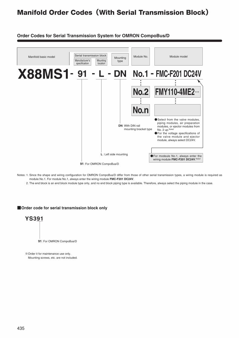
Manifold Order Codes(With Serial Transmission Block)
Order Codes for Serial Transmission System for OMRON CompoBus/D
YS391
Module No. Module model
… …
… …
X88MS1 L91 DN No.1 FMC-F201 DC24V
FMY110-4ME2…No.2
No.n
-- - -
Mountingtype
91: For OMRON CompoBus/D
L : Left side mounting
Notes: 1. Since the shape and wiring configuration for OMRON CompoBus/D differ from those of other serial transmission types, a wiring module is required asmodule No.1. For module No.1, always enter the wiring module FMC-F201 DC24V.
2. The end block is an end block module type only, and no end block piping type is available. Therefore, always select the piping module in the case.
DN: With DIN rail mounting bracket type
Order code for serial transmission block only
91: For OMRON CompoBus/D
※Order it for maintenance use only.※Mounting screws, etc. are not included.
Select from the valve modules,piping modules, air preparationmodules, or ejector modules fromNo. 2 up.Note2
For the voltage specifications ofthe valve module and ejectormodule, always select DC24V.
Serial transmission blockManifold basic model
For modeule No.1, always enter thewiring module FMC-F201 DC24V.Note1
435
Manufacturer’sspecification
Mountinglocation
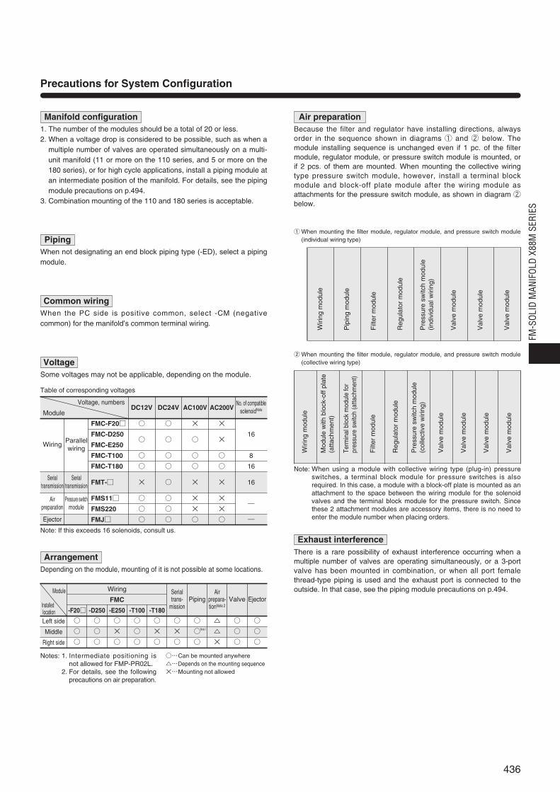
Precautions for System Configuration
Manifold configuration1. The number of the modules should be a total of 20 or less.2. When a voltage drop is considered to be possible, such as when a
multiple number of valves are operated simultaneously on a multi-unit manifold (11 or more on the 110 series, and 5 or more on the180 series), or for high cycle applications, install a piping module atan intermediate position of the manifold. For details, see the pipingmodule precautions on p.494.
3. Combination mounting of the 110 and 180 series is acceptable.
Air preparationBecause the filter and regulator have installing directions, alwaysorder in the sequence shown in diagrams ① and ② below. Themodule installing sequence is unchanged even if 1 pc. of the filtermodule, regulator module, or pressure switch module is mounted, orif 2 pcs. of them are mounted. When mounting the collective wiringtype pressure switch module, however, install a terminal blockmodule and block-off plate module after the wiring module asattachments for the pressure switch module, as shown in diagram ②below.
q When mounting the filter module, regulator module, and pressure switch module(individual wiring type)Piping
When not designating an end block piping type (-ED), select a pipingmodule.
Common wiringWhen the PC side is positive common, select -CM (negativecommon) for the manifold’s common terminal wiring.
VoltageSome voltages may not be applicable, depending on the module.
Voltage, numbersDC12V DC24V AC100V AC200V
Module
FMC-F20 × ×
FMC-D250 16
FMC-E250 ×
FMC-T100 8
FMC-T180 16
FMT- × × × 16
FMS11 × ×―
FMS220 × ×
FMJ ―
Note: If this exceeds 16 solenoids, consult us.
ArrangementDepending on the module, mounting of it is not possible at some locations.
Wiring
FMC
-F20 -D250 -E250 -T100 -T180
Left side
Middle
Right side
No. of compatiblesolenoidNote
Wiring
Table of corresponding voltages
Parallelwiring
Serial transmission
Serial transmission
Airpreparation
Ejector
×
×
×
×
Pressure switchmodule
Val
vem
odul
e
Val
vem
odul
e
Val
vem
odul
e
Pre
ssur
esw
itch
mod
ule
(indi
vidu
alw
iring
)
Reg
ulat
orm
odul
e
Filt
erm
odul
e
Pip
ing
mod
ule
Wiri
ngm
odul
e
w When mounting the filter module, regulator module, and pressure switch module(collective wiring type)
Note: When using a module with collective wiring type (plug-in) pressureswitches, a terminal block module for pressure switches is alsorequired. In this case, a module with a block-off plate is mounted as anattachment to the space between the wiring module for the solenoidvalves and the terminal block module for the pressure switch. Sincethese 2 attachment modules are accessory items, there is no need toenter the module number when placing orders.
Wiri
ngm
odul
e
Mod
ule
with
bloc
k-of
fpla
te(a
ttach
men
t)
Term
inal
bloc
km
odul
efo
rpr
essu
resw
itch
(atta
chm
ent)
Filt
erm
odul
e
Reg
ulat
orm
odul
e
Pre
ssur
esw
itch
mod
ule
(col
lect
ive
wiri
ng)
Val
vem
odul
e
Val
vem
odul
e
Val
vem
odul
e
Val
vem
odul
e
Exhaust interferenceThere is a rare possibility of exhaust interference occurring when amultiple number of valves are operating simultaneously, or a 3-portvalve has been mounted in combination, or when all port femalethread-type piping is used and the exhaust port is connected to theoutside. In that case, see the piping module precautions on p.494.
436
FM-S
OLID
MAN
IFOL
D X8
8M S
ERIE
S
Installedlocation
Notes: 1. Intermediate positioning isnot allowed for FMP-PR02L.
2. For details, see the followingprecautions on air preparation.
…Can be mounted anywhere…Depends on the mounting sequence×…Mounting not allowed
Module Serial trans-
missionPiping
Airprepara-tionNote 2
Valve Ejector
Note 1
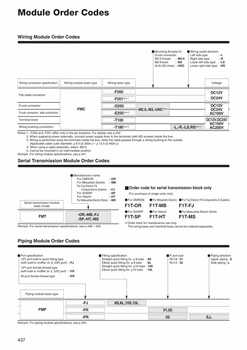
Module Order Codes
Wiring Module Order Codes
Wiring connection specification
Flat cable connector
FMC
-F200
-F201Note 1
-D250
-E250Note 2
-T100
-T180Note 3
Piping Module Order Codes
Piping module basic type
FMP
-FJ 8S,8L,10S,10L
01,02
02 S,L
-FR
-PR
-M2.6,-M3,-UNCNote 4
-L,-R,-LS,RSNote 5
DC12VDC24V
DC12VDC24VAC100V
DC12V,DC24VAC100VAC200V
D-sub connector
D-sub connector, side connection
Terminal block
Wiring bushing connection
Notes:1. -F200 and -F201 differ only in the pin locations. For details, see p.442.2. When supplying power externally, connect power supply lines to the terminals (with M3 screws) inside the box.3. Wiring is performed using the terminals inside the box, while the cable passes through a wiring bushing to the outside.
(Applicable cable outer diameter:φ8.5 [0.335in.]~φ12.5 [0.492in.])4. When using a cable assembly, select -M2.6.5. Cannot be mounted in an intermediate position.
Remark: For wiring module specifications, see p.441.
Remark: For serial transmission specifications, see p.448~449.
Remark: For piping module specifications, see p.454.
Wiring module basic type Wiring basic type Voltage
Mounting threads for D-sub connectorM2.6 thread : -M2.6M3 thread : -M3#4-40-UNC thread : -UNC
Wiring outlet directionLeft side type : -LRight side type : -RLower left side type : -LSLower right side type : -RS
P port sizeRc1/8 : 01Rc1/4 : 02
Piping directionUpper piping : SSide piping : L
Port specification1(P) port built-in quick fitting type (with built-in muffler on 3, 5(R) port) : -FJ
1(P) port female thread type (with built-in muffler on 3, 5(R) port) : -FR
All port female thread type : -PR
Serial Transmission Module Order Codes
Serial transmission module basic model
FMT -OR,-MB,-FJ-SP,-HT,-MS
Manufacture’s nameFor OMRON : -ORFor Mitsubishi Electric : -MBFor Fuji Electric FA
Components & Systems : -FJFor SHARP : -SPFor Hitachi : -HTFor Matsushita Electric Works : -MS
Fitting specificationStraight quick fitting for φ8 tube : 8SElbow quick fitting for φ8 tube : 8LStraight quick fitting for φ10 tube : 10SElbow quick fitting for φ10 tube : 10L
Order code for serial transmission block only(For purchase of single units only)
For OMRON For Mitsubishi Electric For Fuji Electric FA Components & Systems
F1T-OR F1T-MB F1T-FJFor SHARP For Hitachi For Matsushita Electric Works
F1T-SP F1T-HT F1T-MS※Order them for maintenance use only.※The wiring base and manifold base cannot be ordered separately.
437

Air Preparation Module Order Codes
Remark: For the regulator module specifications, see p.457, and for theprecautions, see p.487.
Regulator module basic model
FMR200 -GA20,-GD20
Pressure gauge specification
Without pressure gauge : BlankWith 1MPa [145psi.] specificationφ20 [0.79in.]pressure gauge (bottom piping) : -GA20With 1MPa [145psi.] specificationφ20 [0.79in.]pressure gauge (back piping) : -GD20
Remark: For the filter module specifications, see p.457, and for theprecautions, see p.486.
Filter module basic model
FMF200
Filter module
Regulator module
Remark: For the electronic type pressure switch module specifications, see p.457, and for the precautions, see p.488~492.
Electronic type pressure switchmodule basic model
FMS220 -PS,-PL
Wiring typePlug-in type : Blank (collective wiring type)
Terminal block (FMC-T100), block-off platemodule are included.
With straight connector : -PS (individual wiring type)With elbow connector : -PL (individual wiring type)
Pressure switch module(Electronic type pressure switch module)
Remark: For the mechanical type pressure switch module specifications, seep.457, and for the precautions, see p.491~492.
Mechanical type pressureswitch module basic model
FMS 110,111 A,B -SP
Contact typeReed switch type (2-lead wires) : 110Solid state type (3-lead wires) : 111
Shield plateWithout shield plate: BlankWith shield plate : -SP
Wiring typePlug-in type : Blank (collective wiring type)
Terminal block (FMC-T100), block-off plate module included.Lead wire type : A (individual wiring type) Lead wire length
1000mm [39in.].: B (individual wiring type) Lead wire length
3000mm [118in.].
(Mechanical type pressure switch module)
Order code for filter block only
F1F200
Order code for filter element only
F3F-01
Order codes for regulator block only
F1R200
Pressure gauge specificationBlank : Without pressure gaugeGA20 : With 1MPa [145psi.] specificationφ20 [0.79in.]
pressure gauge (bottom piping)GD20 : With 1MPa [145psi.] specificationφ20 [0.79in.]
pressure gauge (back piping)
Regulator blockbasic model
Order codes for electronic type pressure switch block only
F1S220
Wiring type※Collective wiring type : Blank(plug-in type)Individual wiring type : PS : With straight connector(connector type) PL : With elbow connector
Electronic typepressure switch block basic model
※For orders of the switch block only, the terminalblock and block-off plate modules are not included.
Order codes for mechanical type pressure switch block only
F1S
Shield plateBlank : Without shield plate-SP : With shield plate
Mechanical typepressure switch blockbasic model
※For orders of the switch block only, the terminalblock and block-off plate modules are not included.
Wiring typeCollective wiring type : Blank※(plug-in type)Individual wiring type : A : lead wire length 1000mm [39in.](lead wire type) B : lead wire length 3000mm [118in.]
Contact type110 : Reed switch type (2-lead wires)111 : Solid state type (3-lead wires)
438
FM-S
OLID
MAN
IFOL
D X8
8M S
ERIE
S
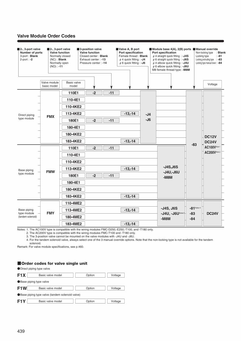
Valve Module Order Codes
Direct pipingtype module FMX
Base pipingtype module FMW
Base pipingtype module (tandem solenoid)
FMY
110E1
110-4E1
110-4KE2
113-4KE2
180E1
180-4E1
180-4KE2
183-4KE2
110E1
110-4ME2
113-4ME2
180-4ME2
183-4ME2
110-4E1
110-4KE2
113-4KE2
180E1
180-4E1
180-4KE2
183-4KE2
-2 -11
-2 -11
-13,-14
-13,-14
-13,-14
-13,-14
-13,-14
-13,-14
-2 -11
-2 -11
-J4-J6
-J4S,J6S-J4U,-J6U-M8M
-83
-81Note 4
-83-84
DC12VDC24VAC100VNote 1
AC200VNote 2
DC24V-J4S, J6S-J4U, -J6UNote 3
-M8M
Valve modulebasic model
Basic valvemodel
Voltage
2-, 3-port valveNumber of ports3-port : Blank2-port : -2
2-, 3-port valveValve functionNormally closed (NC) : BlankNormally open (NO) : -11
3-position valveValve functionClosed center : BlankExhaust center : -13Pressure center : -14
Valve A, B portPort specificationFemale thread : Blankφ4 quick fitting : -J4φ6 quick fitting : -J6
Module base 4(A), 2(B) portsPort specificationφ4 straight quick fitting : -J4Sφ6 straight quick fitting : -J6Sφ4 elbow quick fitting : -J4Uφ6 elbow quick fitting : -J6UM8 female thread type: -M8M
Manual overrideNon-locking type : BlankLocking type : -81Locking protruding type : -83Locking type manual lever : -84
Notes: 1. The AC100V type is compatible with the wiring modules FMC-D250,-E250,-T100, and -T180 only.2. The AC200V type is compatible with the wiring modules FMC-T100 and -T180 only.3. The 3-position valve cannot be mounted on the valve modules with -J4U and -J6U.4. For the tandem solenoid valve, always select one of the 3 manual override options. Note that the non-locking type is not available for the tandem
solenoid.Remark: For valve module specifications, see p.460.
Order codes for valve single unitDirect piping type valve
F1X Base piping type valve
F1WBase piping type valve (tandem solenoid valve)
F1Y VoltageOptionBasic valve model
VoltageOptionBasic valve model
VoltageOptionBasic valve model
439

Ejector Module Order Codes
Base piping typemodule FMJ -11
-J4S-J6S-J4U-J6U-M8M
-83 -E
05E1
Direct piping type
Base piping type
Base piping type(tandem solenoid)
FMX
FMW
FMY
-J4S,-J6S,-J4U,-J6U,-M8M
注-J4S,-J6S,-J4U,-J6U,-M8MNote
注-J4S,-J6S,-J4U,-J6U,-M8MNote
110-BP
180-BP
110-BP
180-BP
110-BP
180-BP
05E2
07E1
07E2
DC12VDC24VAC100VAC200V
Note: The normally open type is only available with the supply air control solenoid valve. The vacuum breaking air control solenoid valve is normally closed.Remarks : 1. Replacement filters are provided as additional parts (to be ordered separately. Order code : ME05MA, ME07MA-F). Replace them periodically.
2. The ejector module is the base piping type only. A direct piping type module is not available.3. For ejector module specifications, see p.476.
Remark: Although FMW and FMY are the same base piping type, their valve modules are incompatible because of different plug-in shapes. Care must beexercised when ordering block-off plate modules for the future addition of valves.
Note: The 3-position valve cannot be mounted on the block-off plate module with -J4U and -J6U.
Ejector modulebasic model
Block-off plate module basic model
Ejectorbasic model
Voltage
Valve functionNormally closed (NC) : BlankNormally open (NO) : -11Note
Module base 2(B) portPort specification(no piping for 4(A) port)φ4 straight quick fitting : -J4Sφ6 straight quick fitting : -J6Sφ4 elbow quick fitting : -J4Uφ6 elbow quick fitting : -J6UM8 female thread type: -M8M
Manual overrideNon-locking type : BlankLocking protruding type : -83
Electronic type vacuum switch Without electronic type vacuumswitch : BlankWith electronic type vacuum switch : -E
Block-off Plate Module Order Codes
Order codes for block-off plate only
For solenoid valves110 series For solenoid valves180 series
F1X110-BP (for FMX) F1X180-BP (for FMX)F1W110-BP (for FMW, FMY) F1W180-BP (for FMW, FMY)
Module base 4(A), 2(B) portsConnection specificationφ4 straight quick fitting : -J4Sφ6 straight quick fitting : -J6Sφ4 elbow quick fitting : -J4Uφ6 elbow quick fitting : -J6UM8 female thread type: -M8M
440
FM-S
OLID
MAN
IFOL
D X8
8M S
ERIE
S
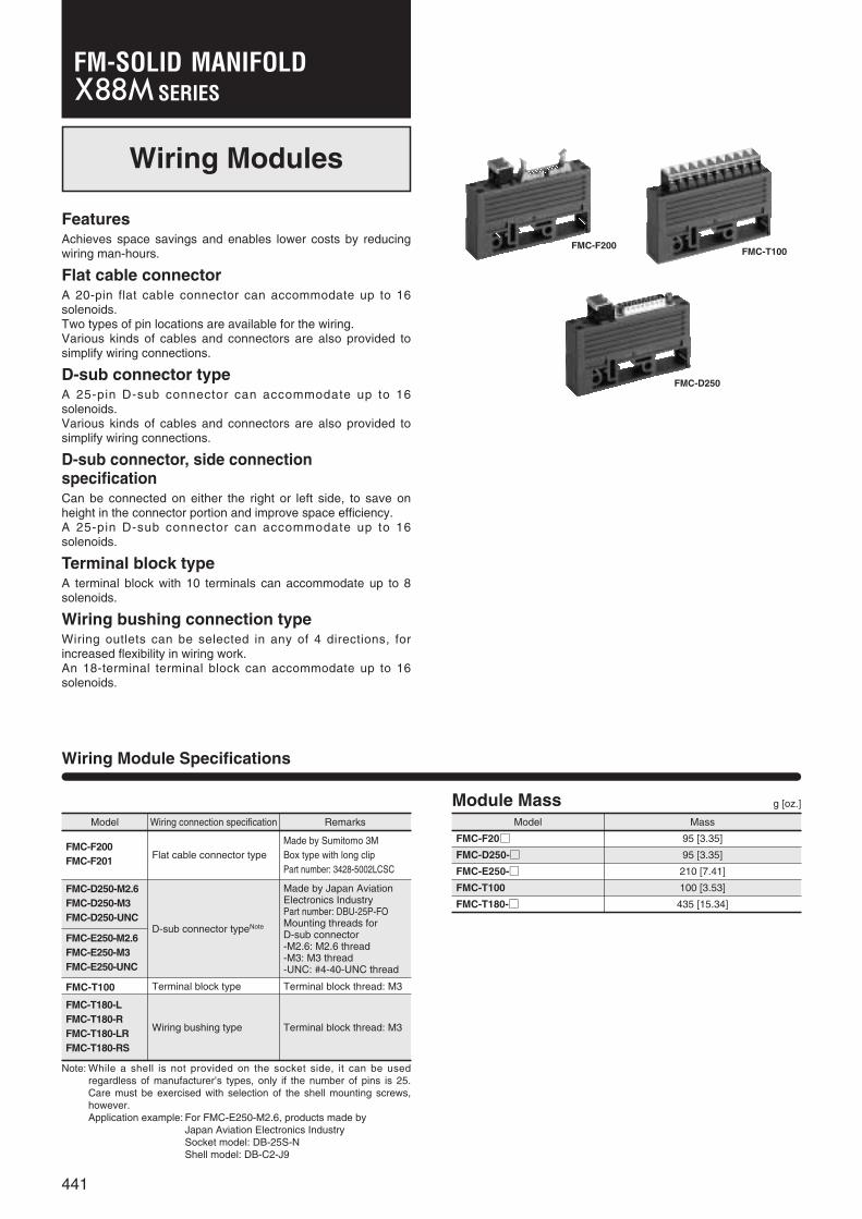
Model Wiring connection specification
Terminal block type Terminal block thread: M3
Remarks
FMC-F200FMC-F201
Flat cable connector typeMade by Sumitomo 3M Box type with long clipPart number: 3428-5002LCSC
FMC-D250-M2.6FMC-D250-M3FMC-D250-UNC
D-sub connector typeNote
Made by Japan AviationElectronics IndustryPart number: DBU-25P-FOMounting threads for D-sub connector-M2.6: M2.6 thread-M3: M3 thread-UNC: #4-40-UNC thread
FMC-E250-M2.6FMC-E250-M3FMC-E250-UNC
FMC-T180-LFMC-T180-RFMC-T180-LRFMC-T180-RS
FMC-T100
Wiring bushing type Terminal block thread: M3
Wiring Module Specifications
Module Mass g [oz.]
Wiring Modules
FeaturesAchieves space savings and enables lower costs by reducingwiring man-hours.
Flat cable connectorA 20-pin flat cable connector can accommodate up to 16solenoids.Two types of pin locations are available for the wiring.Various kinds of cables and connectors are also provided tosimplify wiring connections.
D-sub connector typeA 25-pin D-sub connector can accommodate up to 16solenoids.Various kinds of cables and connectors are also provided tosimplify wiring connections.
D-sub connector, side connection specificationCan be connected on either the right or left side, to save onheight in the connector portion and improve space efficiency.A 25-pin D-sub connector can accommodate up to 16solenoids.
Terminal block typeA terminal block with 10 terminals can accommodate up to 8solenoids.
Wiring bushing connection typeWiring outlets can be selected in any of 4 directions, forincreased flexibility in wiring work.An 18-terminal terminal block can accommodate up to 16solenoids.
Model Mass
FMC-F20 95 [3.35]
FMC-D250- 95 [3.35]
FMC-E250- 210 [7.41]
FMC-T100 100 [3.53]
FMC-T180- 435 [15.34]
Note: While a shell is not provided on the socket side, it can be usedregardless of manufacturer’s types, only if the number of pins is 25.Care must be exercised with selection of the shell mounting screws,however.Application example: For FMC-E250-M2.6, products made by
Japan Aviation Electronics IndustrySocket model: DB-25S-NShell model: DB-C2-J9
FMC-F200FMC-T100
FMC-D250
441
SERIESFM-SOLID MANIFOLD
1 3 5 97 11 13 15 17
2 4 6 108 12 14 16 18
1~16:Control terminals17, 18:Common terminals (short-circuited within module)
Solenoid side
Terminal block
1 2 3 4 5 6 7 8 9 10
1~8:Control terminals9, 10:Common terminals (short-circuited within module)
Solenoid sideTerminal block
1 3 5 7 9 11 13 15 17 19 21 23 25
2 4 6 8 10 12 14 16 18 20 22 24
1~16:Control pins20, 21, 22:(-) pins (short-circuited within module)23, 24, 25:(+) pins (short-circuited within module)
11 12 13 14 15 16 17 18 19 207 8 94 5 61 2 3 10
Triangle mark
1~8:Control pins11~18:Control pins 9, 19:(-) pins (short-circuited within module) 10, 20:(+) pins (short-circuited within module)
19 17 15 13 11 9 7 5 3 120 18 16 14 12 10 8 6 4 2
Triangle mark
1~16:Control pins17, 18:(-) pins (short-circuited within module)19, 20:(+) pins (short-circuited within module)
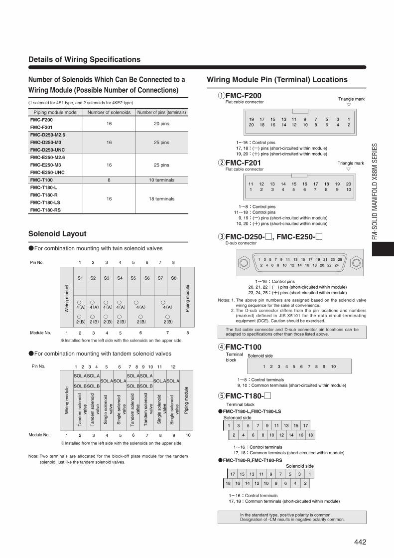
Piping module model Number of solenoids Number of pins (terminals)
FMC-F200
FMC-F20116 20 pins
FMC-D250-M2.6
FMC-D250-M3 16 25 pins
FMC-D250-UNC
FMC-E250-M2.6
FMC-E250-M3 16 25 pins
FMC-E250-UNC
FMC-T100 8 10 terminals
FMC-T180-L
FMC-T180-R16 18 terminals
FMC-T180-LS
FMC-T180-RS
Details of Wiring Specifications
Number of Solenoids Which Can Be Connected to aWiring Module (Possible Number of Connections)
Wiring Module Pin (Terminal) Locations
Solenoid Layout
(1 solenoid for 4E1 type, and 2 solenoids for 4KE2 type)
For combination mounting with twin solenoid valves
For combination mounting with tandem solenoid valves
※Installed from the left side with the solenoids on the upper side.
※Installed from the left side with the solenoids on the upper side.
Note: Two terminals are allocated for the block-off plate module for the tandemsolenoid, just like the tandem solenoid valves.
qFMC-F200Flat cable connector
wFMC-F201Flat cable connector
eFMC-D250-, FMC-E250-D-sub connector
rFMC-T100
tFMC-T180-
FMC-T180-L,FMC-T180-LS
FMC-T180-R,FMC-T180-RS
Notes: 1. The above pin numbers are assigned based on the solenoid valvewiring sequence for the sake of convenience.
2. The D-sub connector differs from the pin locations and numbers(marked) defined in JIS X5101 for the data circuit-terminatingequipment (DCE). Caution should be exercised.
The flat cable connector and D-sub connector pin locations can beadapted to specifications other than those listed above.
In the standard type, positive polarity is common.Designation of -CM results in negative polarity common.
17 15 13 11 9 7 5 3 1
18 16 14 12 10 8 6 4 2
1~16:Control terminals17, 18:Common terminals (short-circuited within module)
Solenoid side
1 2 3 4 5 6 7 8 9 10 11 12
1 2 3 4 5 6 7 8 9 10
SOL.A
SOL.B
SOL.ASOL.ASOL.A
SOL.B
SOL.A
SOL.B
SOL.ASOL.ASOL.A
SOL.B
Pip
ing
mod
ule
Wiri
ng m
odul
e
Sin
gle
sole
noid
val
ve
Pin No.
Module No.
Sin
gle
sole
noid
val
ve
Tan
dem
sol
enoi
d v
alve
Tan
dem
sol
enoi
d v
alve
Sin
gle
sole
noid
val
ve
Sin
gle
sole
noid
val
ve
Tan
dem
sol
enoi
d v
alve
Tan
dem
sol
enoi
d v
alve
4(A)
2(B)
4(A)
2(B)
4(A)
2(B)
4(A)
2(B)
4(A)
2(B)
4(A)
2(B)
S1 S2 S3 S4 S5 S6 S7 S8
1 2 3 4 5
1 2 3 4 5 6 7 8
6 7 8Pin No.
Module No.
Pip
ing
mod
ule
Wiri
ng m
odue
l
442
FM-S
OLID
MAN
IFOL
D X8
8M S
ERIE
S
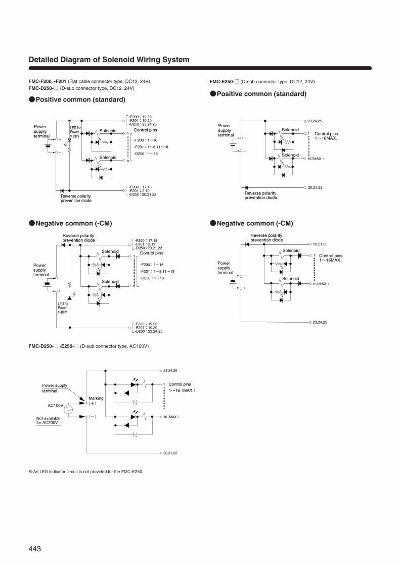
Detailed Diagram of Solenoid Wiring System
FMC-F200, -F201 (Flat cable connector type, DC12, 24V)FMC-D250- (D-sub connector type, DC12, 24V)
Positive common (standard)
Negative common (-CM)
FMC-D250-,-E250- (D-sub connector type, AC100V)
※An LED indicator circuit is not provided for the FMC-E250.
FMC-E250- (D-sub connector type, DC12, 24V)
Positive common (standard)
Negative common (-CM)
LED forPowersupply
Solenoid
Solenoid
-F200:19,20-F201:10,20-D250:23,24,25
-F200:1~16
-F201:1~8,11~18
-D250:1~16
-F200:17,18-F201:9,19-D250:20,21,22
1
n
Control pinsPower supplyterminal
Reverse polarityprevention diode
Solenoid
Solenoid
-F200:19,20-F201:10,20-D250:23,24,25
-F200:17,18-F201:9,19-D250:20,21,22
-F200:1~16
-F201:1~8,11~18
-D250:1~16
1
n
Control pins
Reverse polarityprevention diode
LED forPowersupply
Power supplyterminal
Power supply terminal
23,24,25
20,21,22
1
16(MAX.)
Control pins
AC100V
Marking(+)
(-)
1~16(MAX.)
Not availablefor AC200V
23,24,25
20,21,22
1
16(MAX.)
Solenoid
Solenoid
Control pins1~16MAX.
Reverse polarityprevention diode
Power supplyterminal
23,24,25
20,21,22
1
16(MAX.)
Solenoid
Solenoid
Control pins1~16MAX.
Reverse polarityprevention diode
Power supplyterminal
443
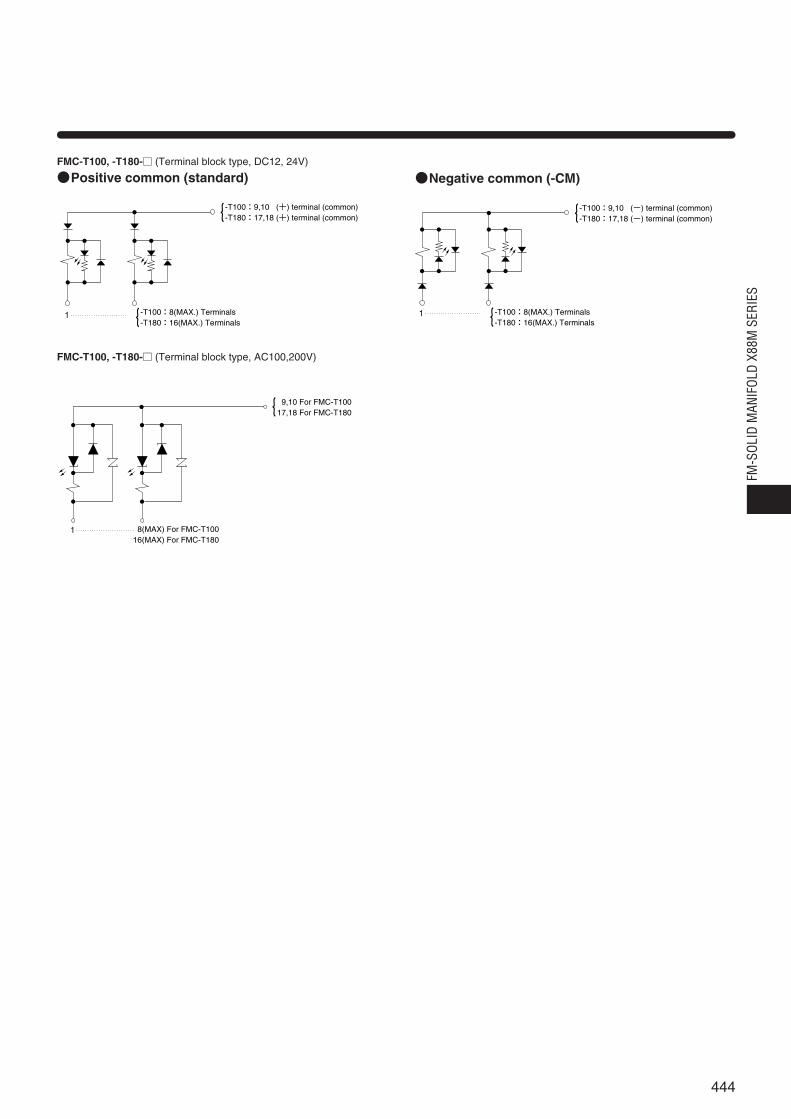
FMC-T100, -T180- (Terminal block type, DC12, 24V)
Positive common (standard) Negative common (-CM)
FMC-T100, -T180- (Terminal block type, AC100,200V)
1
{
{
-T100:9,10 (+) terminal (common)-T180:17,18 (+) terminal (common)
-T100:8(MAX.) Terminals-T180:16(MAX.) Terminals
1
{ 9,10 For FMC-T100
8(MAX) For FMC-T10016(MAX) For FMC-T180
17,18 For FMC-T180
1
{
{
-T100:9,10 (-) terminal (common)-T180:17,18 (-) terminal (common)
-T100:8(MAX.) Terminals-T180:16(MAX.) Terminals
444
FM-S
OLID
MAN
IFOL
D X8
8M S
ERIE
S
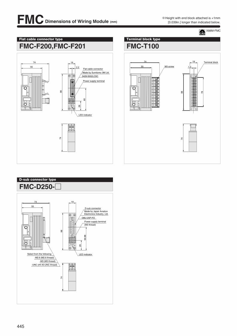
FMC Dimensions of Wiring Module (mm)
Flat cable connector type
FMC-F200,FMC-F201
3428-5002LCSC
74
55
26
9874
60
19
2.2Flat cable connector
Made by Sumitomo 3M Ltd.
Power supply terminal
LED indicator
Terminal block type
FMC-T100
Terminal block
M3 screw
74
55
19
1.5
9874
78
D-sub connector type
FMC-D250-
DBU-25P-FO
LED indicator
74 19
55
26
74
59.9
8
98
Select from the following:
D-sub connector
Power supply terminal
(M3 thread)
-M2.6 (M2.6 thread)
-M3 (M3 thread)
-UNC (#4-40-UNC thread)
Made by Japan Aviation Electronics Industry, Ltd.
※Height with end block attached is +1mm[0.039in.] longer than indicated below.
X88M-FMC
445
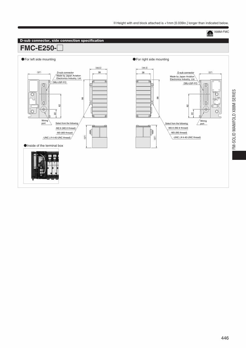
D-sub connector, side connection specification
FMC-E250-
(57)
(44.5)
38
DBU-25P-FO
62
(57)
98
22
Select from the following:
-M2.6 (M2.6 thread)
-M3 (M3 thread)
-UNC (#4-40-UNC thread)
D-sub connectorMade by Japan Aviation Electronics Industry, Ltd.
Wiring port
(44.5)
(57)38
98
DBU-25P-FO
62
22
(57)
D-sub connector
Select from the following:
-M2.6 (M2.6 thread)
-M3 (M3 thread)
-UNC (#4-40-UNC thread)
Made by Japan Aviation Electronics Industry, Ltd.
Wiring port
For left side mounting
Inside of the terminal box
For right side mounting
X88M-FMC
446
FM-S
OLID
MAN
IFOL
D X8
8M S
ERIE
S
※Height with end block attached is +1mm [0.039in.] longer than indicated below.
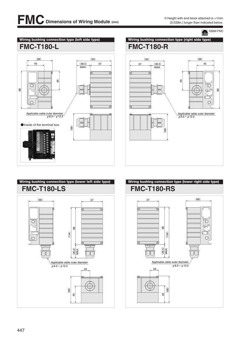
Wiring bushing connection type (left side type)
FMC-T180-L
(68) (93)
(36.5)
(68)
MAX.5745
49
98
Applicable cable outer diameterφ8.5~φ12.5
Wiring bushing connection type (right side type)
FMC-T180-R
(93)
(36.5)MAX.
57
Applicable cable outer diameterφ8.5~φ12.5
(68)
(68)
45
49
98
Wiring bushing connection type (lower left side type)
FMC-T180-LS(68) 57
Applicable cable outer diameterφ8.5~φ12.5
(13
4)
(36
.5)
MA
X.
98
23
(68)
45
Wiring bushing connection type (lower right side type)
FMC-T180-RS57
(13
4)
(36
.5)
MA
X.
98
(68)
Applicable cable outer diameterφ8.5~φ12.5
23
(68)
45
Inside of the terminal box
X88M-FMC
447
FMC Dimensions of Wiring Module (mm)※Height with end block attached is +1mm
[0.039in.] longer than indicated below.
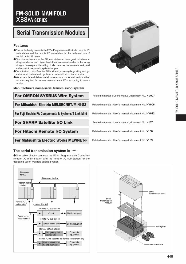
One cable directly connects the PC’s (Programmable Controller) remote I/Omain station and the remote I/O sub-station for the dedicated use ofmanifold solenoid valves.Direct transmission from the PC main station achieves great reductions in
wiring man-hours, and fewer breakdown free operation due to the wrongwiring or breakage in the wiring. It also reduces maintenance work, andenables quick response to system changes.Decentralized control from the PC is allowed, achieving large wiring savings
and reduced costs when long-distance or centralized control is required.We assemble and deliver serial transmission blocks and various other
modules required for various manufacturers’ PCs, according to ordersreceived.
Features
The serial transmission system is・・・・・・One cable directly connects the PC’s (Programmable Controller)remote I/O main station and the remote I/O sub-station for thededicated use of manifold solenoid valves.
Remote I/O sub-station
Remote I/O sub-station
Computer for FA
Programmablecontroller
Computer link line
Remote I/Omain station Upper link unit
Remote I/O sub-station
I/O unit
Various remote units
Electrical equipment
Electrical equipment
Pneumatic equipment
Pneumatic equipment
Manifold solenoid valve for serial transmission
Wiring saving manifoldsolenoid valve
Remote I/O sub-station for the manifold solenoid valve only
Serial trans-mission line
POWER0 1 2 3 4 5 6 7
STATION No.
01234567
RUN T/R ERROR
Serial transmission block
Serial transmission
module
Wiring box
Manifold base
Serial Transmission Modules
Manufacture’s name/serial transmission system
For Hitachi Remote I/O System
For Mitsubishi Electric MELSECNET/MINI-S3
For OMRON SYSBUS Wire System
For SHARP Satellite I/O Link
For Matsushita Electric Works MEWNET-F
For Fuji Electric FA Components & Systems T Link Mini
Related materials : User’s manual, document No. HV007
Related materials : User’s manual, document No. HV006
Related materials : User’s manual, document No. HV012
Related materials : User’s manual, document No. V107
Related materials : User’s manual, document No. V108
Related materials : User’s manual, document No. V109
448
FM-S
OLID
MAN
IFOL
D X8
8M S
ERIE
S
SERIESFM-SOLID MANIFOLD
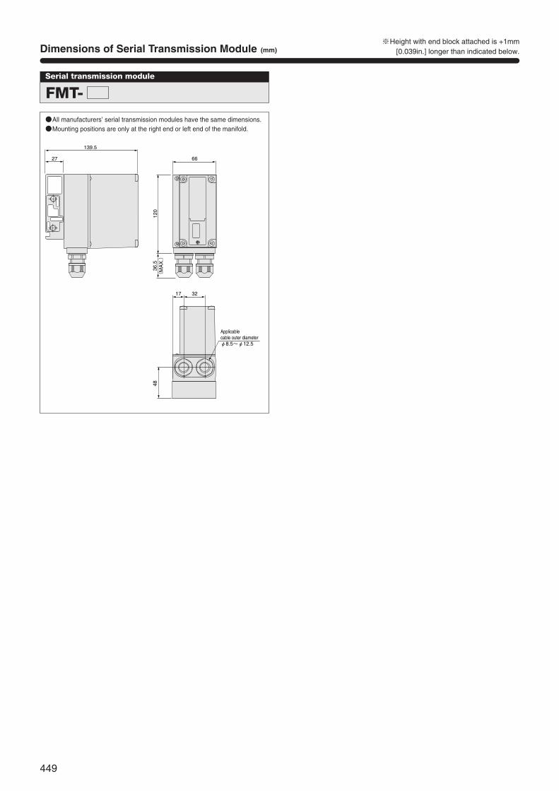
Dimensions of Serial Transmission Module (mm)
FMT-Serial transmission module
139.5
27 6612
036
.5(
MA
X.)
48
3217
Applicable cable outer diameterφ8.5~φ12.5
All manufacturers’ serial transmission modules have the same dimensions.Mounting positions are only at the right end or left end of the manifold.
449
※Height with end block attached is +1mm[0.039in.] longer than indicated below.
For NKE, KURODA PRECISION INDUSTRIES UNI-WIRE® System
Compact Serial Transmission System
Remarks : 1. The UNI-WIRE® System is a serial parallel transmission systemdeveloped jointly by NKE and KURODA PRECISIONINDUSTRIES.
2. For details of each system, see each manufacturer’s catalog,user’s manual, etc.
3. For details on handling the corresponding manifolds, see thecorresponding Koganei user’s manuals.
For Mitsubishi Electric MELSECNET/MINI-S3
For Mitsubishi Electric MELSEC I/O LINK
For Mitsubishi Electric CC-Link
For Fuji Electric FA Components & Systems T Link Mini
For OMRON CompoBus/S
For OMRON SYSBUS Wire System
For OMRON B7A Link Terminal
For SUNX S-LINK
For OMRON CompoBus/D Note
Note: OMRON’s remote I/O adapter-type DRT1-OD16X is used in theserial transmission block forOMRON’s CompoBus/D. Fordetails, see OMRON’s catalog,user’s manual, etc.
For KEYENCE KZ-R
For KOYO ELECTRONICS INDUSTRIES SA Bus
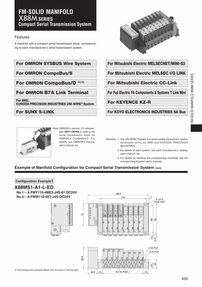
Example of Manifold Configuration for Compact Serial Transmission System (mm)
Features
A manifold with a compact serial transmission block, correspond-ing to each manufacturer’s serial transmission system.
Configuration Example1
X88MS1-A1-L-EDNo.1~4-FMY110-4ME2-J4S-81 DC24VNo.5~8-FMW110-4E1-J4S DC24V
7066
.9
98(
3.4)
29
20(
5)
88
A
B
A
B
A
B
A
B
A
B
A
B
A
B
A
B
144
188.6
30.6 15 15
A
B
DC24V
A B
A
B
DC24V
A B
A
B
DC24V
A B
A
B
DC24V
A B
00 0 0
8×16(Pitch )
7
A B A B A B A B
YS
1A1L
HOLDNC
84
21
BS
-B
DL
BS
+B
DH
FG
PWR
COMMERR
MA
DE
IN JA
PA
N
2(B)Port
4(A)Port
4-φ4.3(Oval hole)
※This configuration example differs from the photo in the top right.
450
FM-S
OLID
MAN
IFOL
D X8
8M S
ERIE
S
SERIESFM-SOLID MANIFOLD

Example of Manifold Configuration for Compact Serial Transmission System (mm)
X88MS1-91-L-DNNo.1-FMC-F201 DC24VNo.2~9 - FMY110-4ME2-J4S-81 DC24VNo.10-FMP-PR02S
A
B
DC24V
BA
BA
A
B
DC24V
BA
BA
A
B
DC24V
BA
BA
A
B
DC24V
BA
BA
A
B
DC24V
BA
BA
A
B
DC24V
BA
BA
A
B
DC24V
BA
BA
A
B
DC24V
BA
BA
0 0 0 0 0 0 0 0
B
A
B
A
B
A
B
A
B
A
B
A
B
A
B
A
P
R
PR
+
OUT
NSMS
REMOTE ADAPTER 24VDCDRT1-OD16X
85
(5) 8
182
196
323
50 35
5.5
88
5.25
103
(72
.5)
56
1320
(91
.5)
(44
.5)
40
1(P)Port
OMRON remote adapterSerial transmission block
Model: DRT1-OD16X2(B)Port
4(A)Port
3, 5(R)Port
451
Configuration Example 2 For CompoBus/D
ON
1 2 3 4 5 6 7 8
DG 24V DG0V 24V0V
SENDPOWER
SHLD L24V
ON1
23
45
67
8
L+ L-24V 0V
PWR ERR
LOADOFF HOLD
ERR SIG
Station number setting switchOutput selecting switch in faulty operationSwitch for address setting and output processing setting during error occurrences
POWER ERROR
ON
1 2 3 4 5 6 7 8
D G 24V D0V 24V 0V
POWER SEND
24V 0V
09
87
6 54
32
13 E 09
87
6 54
32
13 E
RDA RDB SDA SDB SG FG
PWR RUN ERR
S D R D ONOFF
ADDRESS×10 ×1
+- 24V 0V
O N1 2 3 4 5 6
RUNT/RERR
TERM
ONOFF
G FG
Address setting swtich Rotary switch for station number setting
E. C. MODE switch
Dip switch for various settings
End station setting switch
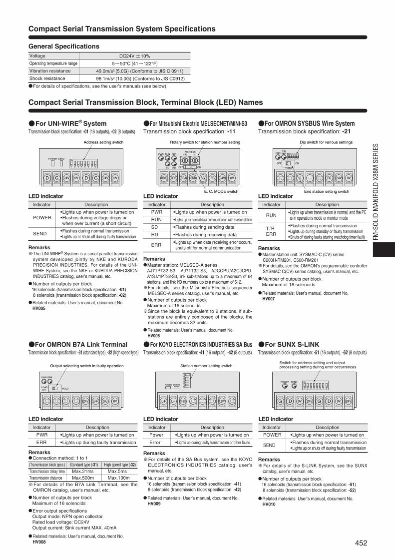
Compact Serial Transmission System Specifications
Compact Serial Transmission Block, Terminal Block (LED) Names
General SpecificationsVoltage
Operating temperature range
Vibration resistance
Shock resistance
For details of specifications, see the user’s manuals (see below).
DC24V ±10%
5~50°C [41~122°F]
49.0m/s2 5.0G (Conforms to JIS C 0911)
98.1m/s2 10.0G (Conforms to JIS C0912)
452
FM-S
OLID
MAN
IFOL
D X8
8M S
ERIE
S
For OMRON SYSBUS Wire SystemTransmission block specification: -21
For Mitsubishi Electric MELSECNET/MINI-S3Transmission block specification: -11
For UNI-WIRE® SystemTransmission block specification: -01 (16 outputs), -02 (8 outputs)
LED indicatorIndicator Description
•Lights up when power is turned onPOWER •Flashes during voltage drops or
when over current (a short circuit)
SEND •Flashes during normal transmission•Lights up or shuts off during faulty transmission
LED indicatorIndicator Description
RUN •Lights up when transmission is normal, and the PCis in operations mode or monitor mode
T/R •Flashes during normal transmission
ERR •Lights up during standby or faulty transmission•Shuts off during faults (during watchdog timer fault)
LED indicatorIndicator Description
PWR •Lights up when power is turned on
RUN •Lights up for normal data communication with master station
SD •Flashes during sending data
RD •Flashes during receiving data
ERR •Lights up when data receiving error occurs,shuts off for normal communication
For OMRON B7A Link TerminalTransmission block specification: -31 (standard type), -32 (high speed type)
RemarksConnection method: 1 to 1(Transmission block spec.) Standard type (-31) High speed type (-32)Transmission delay time Max.31ms Max.5msTransmission distance Max.500m Max.100m※For details of the B7A Link Terminal, see the
OMRON catalog, user’s manual, etc.
Number of outputs per blockMaximum of 16 solenoids
Error output specificationsOutput mode: NPN open collectorRated load voltage: DC24VOutput current: Sink current MAX. 40mA
Related materials: User’s manual, document No.HV008
For KOYO ELECTRONICS INDUSTRIES SA BusTransmission block specification: -41 (16 outputs), -42 (8 outputs)
LED indicatorIndicator Description
PWR •Lights up when power is turned on
ERR •Lights up during faulty transmission
LED indicatorIndicator Description
Power •Lights up when power is turned on
Error •Lights up during faulty transmission or other faults
For SUNX S-LINKTransmission block specification: -51 (16 outputs), -52 (8 outputs)
LED indicatorIndicator Description
POWER •Lights up when power is turned on
SEND •Flashes during normal transmission•Lights up or shuts off during faulty transmission
Remarks※For details of the SA Bus system, see the KOYO
ELECTRONICS INDUSTRIES catalog, user’smanual, etc.
Number of outputs per block16 solenoids (transmission block specification: -41)8 solenoids (transmission block specification: -42)
Related materials: User’s manual, document No.HV009
Remarks※For details of the S-LINK System, see the SUNX
catalog, user’s manual, etc.
Number of outputs per block16 solenoids (transmission block specification: -51)8 solenoids (transmission block specification: -52)
Related materials: User’s manual, document No.HV010
Remarks※The UNI-WIRE® System is a serial parallel transmission
system developed jointly by NKE and KURODAPRECISION INDUSTRIES. For details of the UNI-WIRE System, see the NKE or KURODA PRECISIONINDUSTRIES catalog, user’s manual, etc.
Number of outputs per block16 solenoids (transmission block specification: -01)8 solenoids (transmission block specification: -02)
Related materials: User’s manual, document No. HV005
RemarksMaster station: MELSEC-A series
AJ71PT32-S3, AJ71T32-S3, A2CCPU/A2CJCPU,A1SJ71PT32-S3, link sub-stations up to a maximum of 64stations, and link I/O numbers up to a maximum of 512.※For details, see the Mitsubishi Electric’s sequencer
MELSEC-A series catalog, user’s manual, etc.Number of outputs per block
Maximum of 16 solenoids※Since the block is equivalent to 2 stations, if sub-
stations are entirely composed of the blocks, themaximum becomes 32 units.
Related materials: User’s manual, document No. HV006
RemarksMaster station unit: SYSMAC-C (CV) series
C200H-RM201, C500-RM201※For details, see the OMRON’s programmable controller
SYSMAC C(CV) series catalog, user’s manual, etc.
Number of outputs per blockMaximum of 16 solenoids
Related materials: User’s manual, document No. HV007

24V 0VS1 S2 SD FG
PWR ALM
ON OFF HOLD CLEAR
24V 0V
09
87
6 54
32
13 E
S+ S- RUN FG
POWER/ERROR
ERROR MODE
ADDRESS
24V 0V
0 1 2
34
5
6
789A
BC
DE
F3 E
DATA DG FG
PW RUN ERR.
S D R D
ST. NO.0
9
87
6 54
32
13 E 09
87
6 54
32
13 E
ADDRESS×10 ×1
ON/OFF switch for terminating resistance
Address setting switchStation number setting switch Station number setting switch
Error holding swtich
1 10 ON
MS NS
Transmission connector
Power supply terminalfor internal circuit
Dip switch
O N1 2 3 4 5 6
PWR COMM ERR
Dip switch for various settings
FGBS-BS+ BDH BDL DB DA
0
8
6 4
2
0
8
6 4
2
0
8
6 4
2
24G +24V SLD DG(FG)
PW L RUN L ERR.
S D R D
HOLD CLEAR
B RATE STATION NO.×10 ×1
Station number setting switchTransmission speed setting switch
HOLD/CLEAR switch
453
For Fuji Electric FA Components & Systems T Link Mini
Transmission block specification: -71
Remarks※For details of the T Link Mini, see the Fuji Electric
FA Components & Systems catalog, user’smanual, etc.
Number of outputs per blockMaximum of 16 solenoids
Related materials: User’s manual, document No.HV012
For Mitsubishi Electric MELSEC I/O LINKTransmission block specification: -61
Remarks16 remote I/O unit connection stations, for a maximum
of 128 inputs/outputs ※For details, see Mitsubishi Electric’s sequencer catalog,
user’s manual, etc.
Number of outputs per blockMaximum of 16 solenoids※Since the block is equivalent to 4 stations, if sub-
stations are entirely composed of the blocks, amaximum of 4 units can be connected to 1 master unit.
Related materials: User’s manual, document No.HV011
For OMRON CompoBus/D Transmission block specification: -91
Remarks※For details of the CompoBus/D, see the OMRON
catalog, user’s manual, etc.※The transmission block is OMRON’s remote
adaptor-type DRT1-OD16X. For details abouthandling, see OMRON’s user’s manual.
Number of outputs per blockMaximum of 16 solenoids
Related materials: User’s manual, document No.HV014
Lights up
Flashing
Lights up
Flashing
Shuts off
Lights up
Flashing
Lights up
Flashing
Shuts off
LED indicator
Indicator State Color Description
MS
NS
•Normal state
•No setting state
•Serious breakdown
•Minor breakdown
•No power supply
•Communication connection completed
•No communication connection
•Serious communication fault
•Minor communication fault
•No power supply
Green
Red
Green
Red
For KEYENCE KZ-RTransmission block specification: -81
LED indicatorIndicator Description
PWR •Lights up when power is turned on
ALM •Lights up during faulty transmission
LED indicatorIndicator Description
•Green: Lights up for normal communications state
•Orange: Lights up when communi-cations state is poor
POWER/ (can also light up when ERROR address settings are
incorrect)•Red: Lights up during faulty
operation, or when transmission is cut off
LED indicatorIndicator Description
PW •Lights up when power is turned on
RUN •Lights up when receiving data transmittedfrom master unit is normal
SD •Lights up during sending data to master unit
RD •Lights up during receiving data from master unit
ERR. •Lights up when faulty data transmitted from master unit
Remarks※For details of the KZ-R, see the KEYENCE
catalog, user’s manual, etc.
Number of outputs per blockMaximum of 16 solenoids
Related materials: User’s manual, document No.HV013
For OMRON CompoBus/STransmission block specification: -A1 (16 outputs), -A2 (8 outputs)
Remarks※For details of the CompoBus/S, see the OMRON catalog,
user’s manual, etc.
Number of outputs per block16 solenoids (transmission block specification: -A1)8 solenoids (transmission block specification: -A2)
Related materials: User’s manual, document No.HV015
Lights up
Shuts off
Lights up
Shuts off
Lights up
Shuts off
Green
Yellow
Red
LED indicator
Indicator State Color Description
PWR
COMM
ERR
•During power supply
•Power not supplied
•During normal communication
•Communication fault, or standby
•Communication fault occurred
•During normal communication, or standby
For Mitsubishi Electric CC-LinkTransmission block specification: -B1
LED indicatorIndicator Description
PW
L RUN
SD
RD
L ERR.
•Lights up when power is turned on
•Lights up when normal data is receivedfrom master station
•Lights up during sending data
•Lights up during receiving data
•Lights up during transmission errors, andshuts off when time is overLights up during station number setting erroror transmission speed setting error
Remarks※For details of the CC-Link, see the Mitsubishi Electric
catalog, user’s manual, etc.
Number of outputs per block16 solenoids (transmission block specification: -B1)※Since the block occupies 1 station, if remote I/O
stations are entirely composed of the blocks, amaximum of 64 units can be connected to 1 masterstation.
Related materials: User’s manual, document No.HV016
For about specifications and handling details, see the above-listed user’s manuals (document Nos. HV005~HV016).
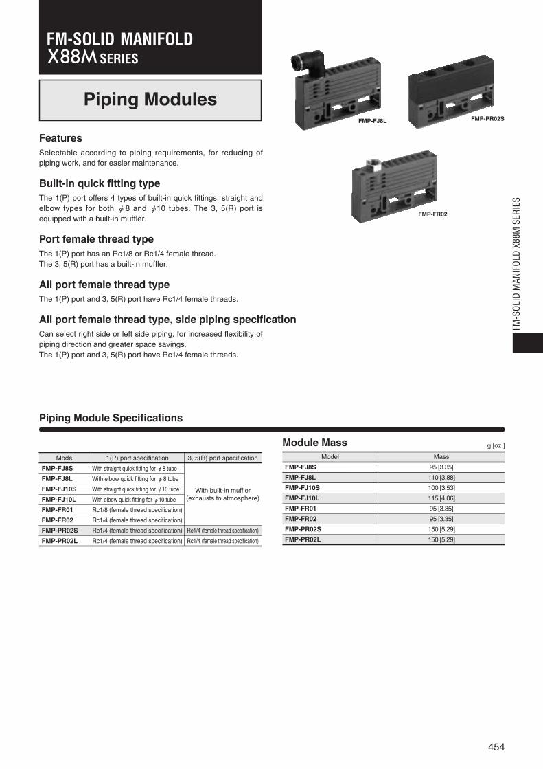
Piping Modules
Piping Module Specifications
FeaturesSelectable according to piping requirements, for reducing ofpiping work, and for easier maintenance.
Built-in quick fitting typeThe 1(P) port offers 4 types of built-in quick fittings, straight andelbow types for both φ8 and φ10 tubes. The 3, 5(R) port isequipped with a built-in muffler.
Port female thread typeThe 1(P) port has an Rc1/8 or Rc1/4 female thread.The 3, 5(R) port has a built-in muffler.
All port female thread typeThe 1(P) port and 3, 5(R) port have Rc1/4 female threads.
All port female thread type, side piping specificationCan select right side or left side piping, for increased flexibility ofpiping direction and greater space savings.The 1(P) port and 3, 5(R) port have Rc1/4 female threads.
Model 1(P) port specification 3, 5(R) port specification
FMP-FJ8S
FMP-FJ8L
FMP-FJ10S
FMP-FJ10L
FMP-FR01
FMP-FR02
FMP-PR02S
FMP-PR02L
With straight quick fitting for φ8 tube
With built-in muffler(exhausts to atmosphere)
With elbow quick fitting for φ8 tube
With straight quick fitting for φ10 tube
With elbow quick fitting for φ10 tube
Rc1/8 (female thread specification)
Rc1/4 (female thread specification)
Rc1/4 (female thread specification)
Rc1/4 (female thread specification)
Rc1/4 (female thread specification)
Rc1/4 (female thread specification)
Module Mass
FMP-FJ8S
Model Mass
g [oz.]
110 [3.88]FMP-FJ8L
FMP-FJ10S
FMP-FJ10L
FMP-FR01
FMP-FR02
FMP-PR02S
FMP-PR02L
95 [3.35]
115 [4.06]
100 [3.53]
95 [3.35]
95 [3.35]
150 [5.29]
150 [5.29]
FMP-FJ8L
FMP-FR02
FMP-PR02S
454
FM-S
OLID
MAN
IFOL
D X8
8M S
ERIE
S
SERIESFM-SOLID MANIFOLD

FMP Dimensions of Piping Module (mm)
Built-in straight quick fitting type
FMP-FJ8S,FMP-FJ10S
1(P)Port
55
19
98
22
17(-J10S)9.4(-J8S)
72(
-J10
S)
64.4(
-J8S)
P
1(P) port female thread type
FMP-FR01,FMP-FR02
55 7
62
19
98
22
62
P
Exhaust port
16 (Width across flats)
-FR01: Rc1/8
-FR02: Rc1/4
1(P)Port
Built-in elbow quick fitting type
FMP-FJ8L,FMP-FJ10L
55
19
98
22
20.5(-FJ10L)16.5(-FJ8L)
29.3(-FJ10L)23.8(-FJ8L)
26.5(
-FJ1
0L)
22.9(
-FJ8
L)
84.3(
-FJ1
0L)
78.8(
-FJ8
L)
1(P)Port
All port female thread type
FMP-PR02S
55
19
98
2545
22
55
3-Rc1/4
P
R
PR
3, 5(R)Port
1(P)Port
X88M-FP1X88M-FP2
455
※Height with end block attached is +1mm [0.039in.]longer than indicated below.
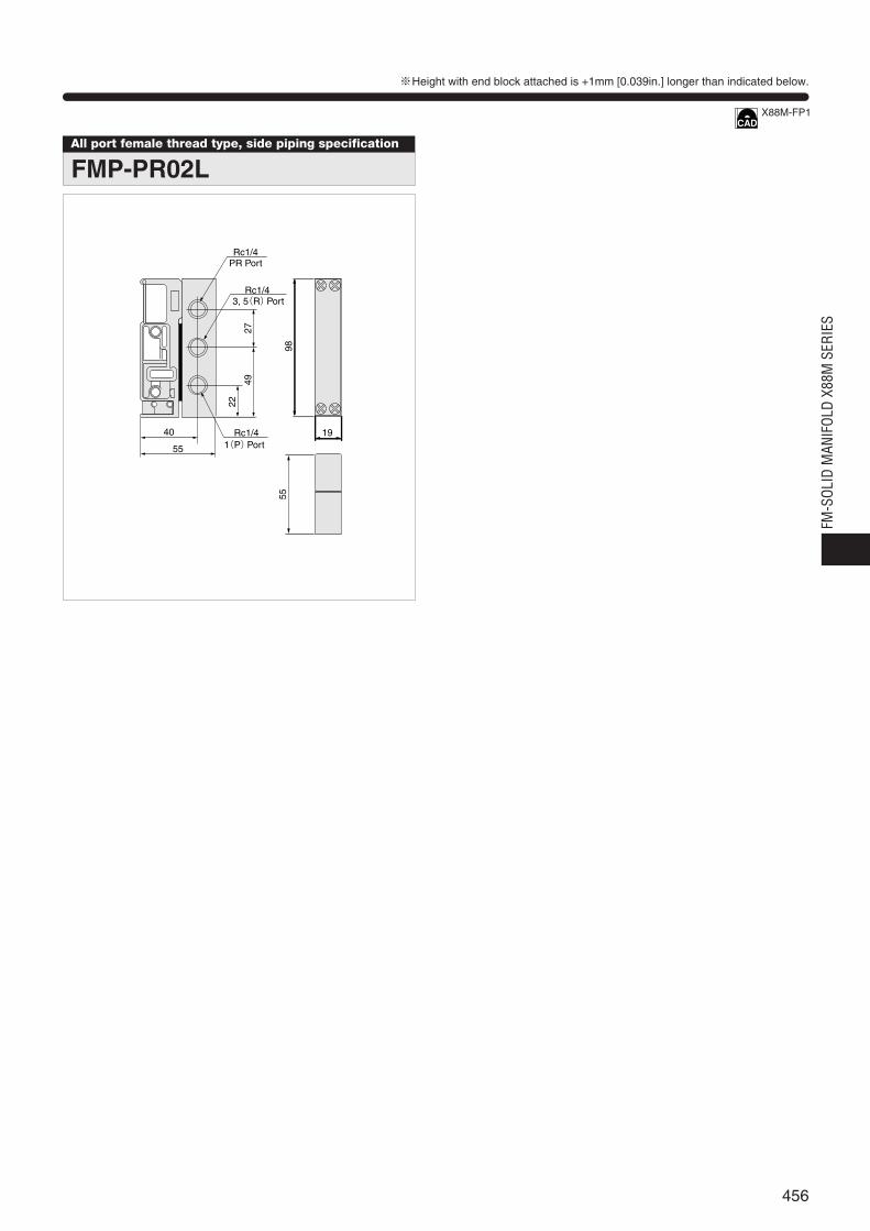
All port female thread type, side piping specification
FMP-PR02L
2749
9855
22
40 19
55
Rc1/4PR Port
Rc1/43, 5(R)Port
Rc1/41(P)Port
※Height with end block attached is +1mm [0.039in.] longer than indicated below.
X88M-FP1
456
FM-S
OLID
MAN
IFOL
D X8
8M S
ERIE
S
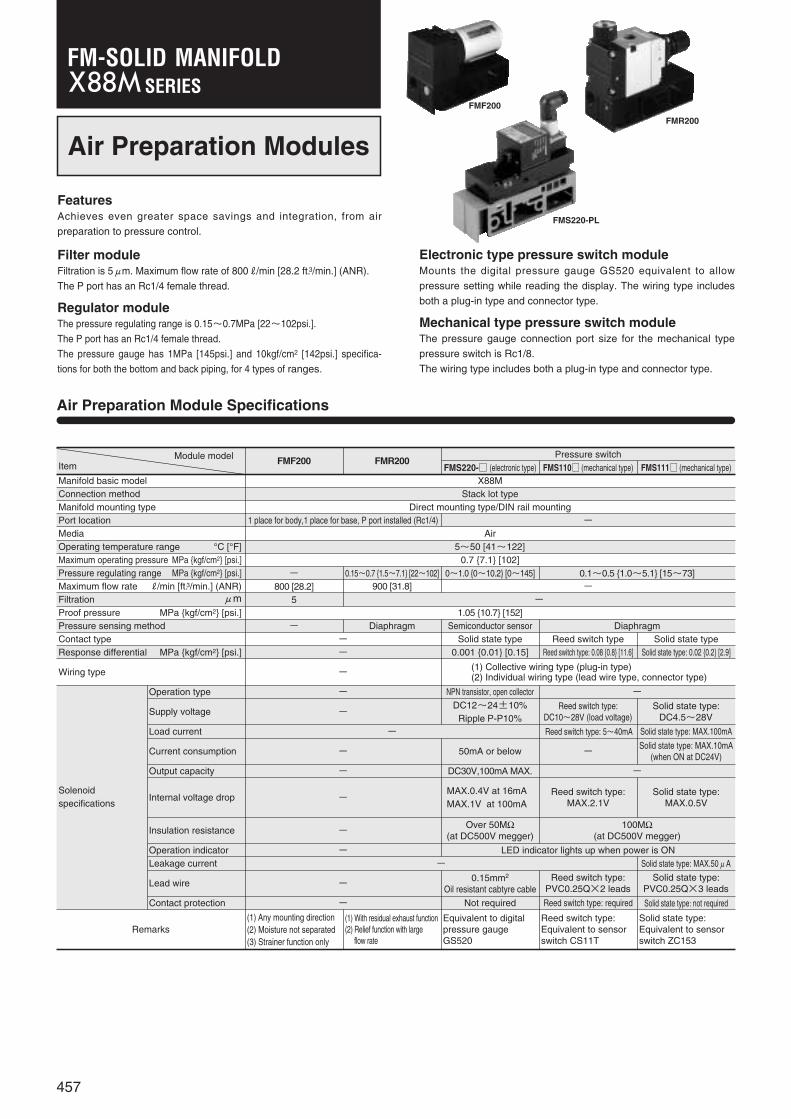
Air Preparation Modules
FeaturesAchieves even greater space savings and integration, from air
preparation to pressure control.
Filter moduleFiltration is 5μm. Maximum flow rate of 800R/min [28.2 ft.3/min.] (ANR).
The P port has an Rc1/4 female thread.
Regulator moduleThe pressure regulating range is 0.15~0.7MPa [22~102psi.].
The P port has an Rc1/4 female thread.
The pressure gauge has 1MPa [145psi.] and 10kgf/cm2 [142psi.] specifica-
tions for both the bottom and back piping, for 4 types of ranges.
Electronic type pressure switch moduleMounts the digital pressure gauge GS520 equivalent to allow
pressure setting while reading the display. The wiring type includes
both a plug-in type and connector type.
Mechanical type pressure switch moduleThe pressure gauge connection port size for the mechanical type
pressure switch is Rc1/8.
The wiring type includes both a plug-in type and connector type.
Air Preparation Module Specifications
Module modelItem FMF200 FMR200
Pressure switchFMS220- (electronic type) FMS110 (mechanical type) FMS111 (mechanical type)
Manifold basic modelConnection methodManifold mounting typePort locationMediaOperating temperature range °C [°F]Maximum operating pressure MPa kgf/cm2 [psi.]Pressure regulating range MPa kgf/cm2 [psi.]Maximum flow rate R/min [ft.3/min.] (ANR)Filtration μmProof pressure MPa kgf/cm2 [psi.]Pressure sensing methodContact typeResponse differential MPa kgf/cm2 [psi.]
Wiring type
Remarks
Operation type
Supply voltage
Load current
Current consumption
Output capacity
Internal voltage drop
Insulation resistance
Operation indicatorLeakage current
Lead wire
Contact protection
-
-
-
- Reed switch type: 5~40mA
-
-
-Reed switch type:
MAX.2.1V
Solid state type: MAX.100mA
Solid state type:MAX.0.5V
-
-
-
-
NPN transistor, open collectorDC12~24±10%
Ripple P-P10%
50mA or below
DC30V,100mA MAX.
MAX.0.4V at 16mAMAX.1V at 100mA
Over 50MΩ(at DC500V megger)
LED indicator lights up when power is ON
0.15mm2
Oil resistant cabtyre cable
Not required
-Reed switch type:
DC10~28V (load voltage)Solid state type:
DC4.5~28V
-Solid state type: MAX.10mA
(when ON at DC24V)
-
100MΩ(at DC500V megger)
Reed switch type:PVC0.25Q×2 leads
Reed switch type: required
Solid state type:PVC0.25Q×3 leads
Solid state type: not required
(1) Any mounting direction(2) Moisture not separated(3) Strainer function only
(1) With residual exhaust function(2) Relief function with large
flow rate
Equivalent to digitalpressure gaugeGS520
Reed switch type:Equivalent to sensorswitch CS11T
Solid state type: Equivalent to sensorswitch ZC153
- Solid state type: MAX.50μA
(1) Collective wiring type (plug-in type)(2) Individual wiring type (lead wire type, connector type)
X88MStack lot type
Direct mounting type/DIN rail mounting1 place for body,1 place for base, P port installed (Rc1/4) -
Air5~50 [41~122]
0.7 7.1 [102]-
800 [28.2]5
1.05 10.7 [152]
0.15~0.7 1.5~7.1 [22~102]900 [31.8]
0~1.0 0~10.2 [0~145]-
0.1~0.5 1.0~5.1 [15~73]
---
Diaphragm Semiconductor sensor DiaphragmSolid state type
0.001 0.01 [0.15]Reed switch type
Reed switch type: 0.08 0.8 [11.6]Solid state type
Solid state type: 0.02 0.2 [2.9]
-
FMS220-PL
FMF200
FMR200
457
Solenoid specifications
SERIESFM-SOLID MANIFOLD
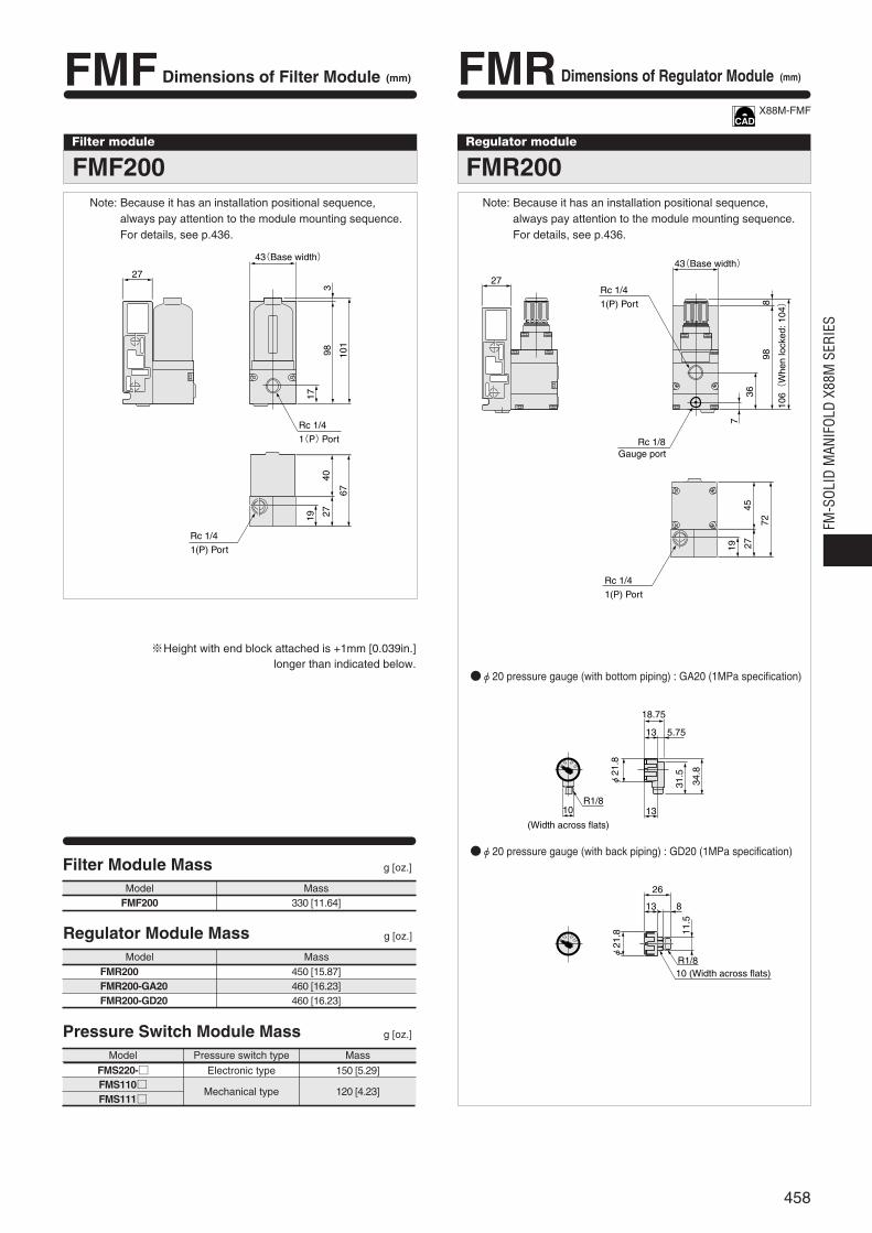
Filter module
FMF200
27
98
17
3
101
40
67
2719
43(Base width)
Rc 1/4
1(P)Port
Rc 1/4
1(P) Port
FMF Dimensions of Filter Module (mm)
※Height with end block attached is +1mm [0.039in.] longer than indicated below.
Regulator module
FMR200
FMR Dimensions of Regulator Module (mm)
Filter Module Mass g [oz.]
Model MassFMF200 330 [11.64]
Regulator Module Mass g [oz.]
Model MassFMR200 450 [15.87]FMR200-GA20 460 [16.23]FMR200-GD20 460 [16.23]
Pressure Switch Module Mass g [oz.]
Model Pressure switch type Mass
FMS220-FMS110FMS111
Electronic type 150 [5.29]
Mechanical type 120 [4.23]
φ20 pressure gauge (with bottom piping) : GA20 (1MPa specification)
φ20 pressure gauge (with back piping) : GD20 (1MPa specification)
27
98
36
7
8
45
72
2719
43(Base width)
106(
Whe
n lo
cked
: 104)
Rc 1/4
1(P) Port
Rc 1/4
1(P) Port
Rc 1/8Gauge port
18.75
5.7513
13
φ21
.8
R1/810
(Width across flats)
31.5
34.8
φ21
.8 11.5
13
26
8
R1/810 (Width across flats)
Note: Because it has an installation positional sequence,always pay attention to the module mounting sequence.For details, see p.436.
Note: Because it has an installation positional sequence,always pay attention to the module mounting sequence.For details, see p.436.
X88M-FMF
458
FM-S
OLID
MAN
IFOL
D X8
8M S
ERIE
S
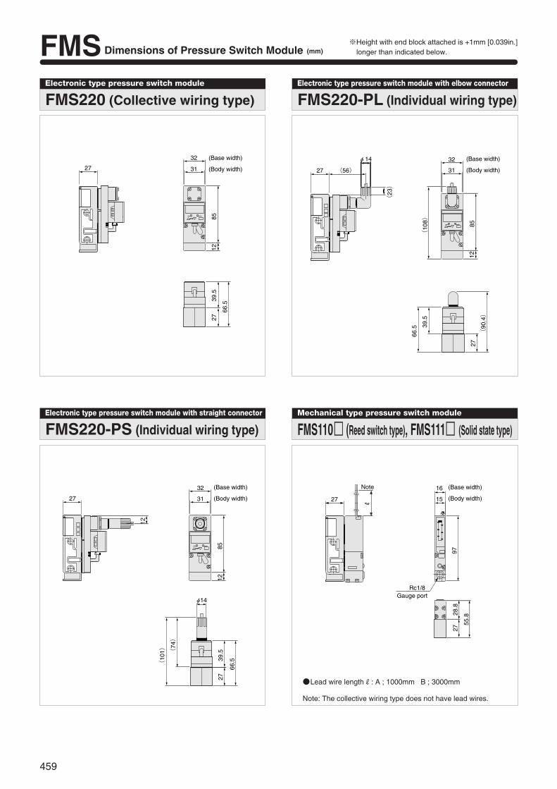
FMS Dimensions of Pressure Switch Module (mm)
Electronic type pressure switch module
FMS220 (Collective wiring type)
0
27
32
8539
.527
66.5
12
31
(Base width)
(Body width)
Electronic type pressure switch module with elbow connector
FMS220-PL (Individual wiring type)
0
27 (56)
(23)
32φ14
85
(10
8)
66.5 39
.5
27
(90
.4)
12
31
(Base width)
(Body width)
Electronic type pressure switch module with straight connector
FMS220-PS (Individual wiring type)
0
27
φ14
32
31
12
85
66.539
.527
(74)
(10
1)
12
(Base width)
(Body width)
Mechanical type pressure switch module
FMS110 (Reed switch type), FMS111 (Solid state type)
27
Note
Rc1/8Gauge port
16
15
R
97
55.828
.827
(Base width)
(Body width)
Lead wire lengthR: A ; 1000mm B ; 3000mm
Note: The collective wiring type does not have lead wires.
459
※Height with end block attached is +1mm [0.039in.]longer than indicated below.
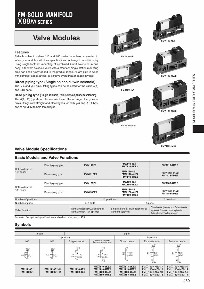
Valve Modules
FeaturesReliable solenoid valves 110 and 180 series have been converted to
valve type modules with their specifications unchanged. In addition, by
using single-footprint mounting of combined 2-unit solenoids in one
body, a tandem solenoid valve with a standard single station mounting
area has been newly added to the product range. All are plug-in types
with compact appearances, to achieve even greater space savings.
Direct piping type (Single solenoid, twin solenoid)The φ4 and φ6 quick fitting types can be selected for the valve 4(A)
and 2(B) ports.
Base piping type (Single solenoid, twin solenoid, tandem solenoid)The 4(A), 2(B) ports on the module base offer a range of 4 types of
quick fittings with straight and elbow types for both φ4 and φ6 tubes,
and of an M8M female thread type.
Valve Module Specifications
Symbols
1(P)5(R1)
4(A) 1(P)5(R1)
4(A)1(P)3(R2)
2(B)4(A) 5(R1)
1(P)3(R2)
2(B)4(A) 5(R1)
1(P)3(R2)
2(B)4(A) 5(R1)
1(P)3(R2)
2(B)4(A) 5(R1)
1(P)3(R2)
2(B)4(A) 5(R1)
Basic Models and Valve Functions
Solenoid valves110 series
Direct piping type
Base piping type
FMX110E1
FMW110E1
FMX110-4E1FMX110-4KE2
FMW110-4E1FMW110-4KE2FMY110-4ME2
FMX113-4KE2
FMW113-4KE2FMY113-4ME2
Solenoid valves180 series
Direct piping type
Base piping type
FMX180E1
FMW180E1
FMX180-4E1FMX180-4KE2
FMW180-4E1FMW180-4KE2FMY180-4ME2
FMX183-4KE2
FMW183-4KE2FMY183-4ME2
Number of positions
Number of ports
Valve function
2 positions 3 positions
2, 3 ports 5 ports
Normally closed (NC, standard) orNormally open (NO, optional)
Single solenoid, Twin solenoid, orTandem solenoid
Closed center (standard), or Exhaust center(optional), Pressure center (optional),Twin solenoid, Tandem solenoid
Remarks: For optional specifications and order codes, see p. 439.
3-port
2-position
NC NO Single solenoid Twin solenoidTandem solenoid Closed center Exhaust center Pressure center
FM110E1FM180E1
FM110E1-11FM180E1-11
FM110-4E1FM180-4E1
FM110-4KE2FM110-4ME2FM180-4KE2FM180-4ME2
FM113-4KE2FM113-4ME2FM183-4KE2FM183-4ME2
FM113-4KE2-13FM113-4ME2-13FM183-4KE2-13FM183-4ME2-13
FM113-4KE2-14FM113-4ME2-14FM183-4KE2-14FM183-4ME2-14
3-position
5-port
FMW110-4E1
FMW110-4KE2
FMW180-4KE2
FMY180-4ME2
FMX110-4E1
FMX180-4E1
FMY110-4ME2
FMX180-4E1
460
FM-S
OLID
MAN
IFOL
D X8
8M S
ERIE
S
SERIESFM-SOLID MANIFOLD

Port Size
Direct piping type
FMX110E1FMX110-4E1FMX110-4KE2FMX113-4KE2
Standard
Optional※-J4※
-J6※
Female thread
Quick fitting for φ4
Quick fitting for φ6
Optional-J4
-J6
Quick fitting for φ4
Quick fitting for φ6
M5×0.8
Base piping type
FMW110E1FMW110-4E1FMW110-4KE2FMW113-4KE2FMY110-4ME2FMY180-4ME2
Direct piping type
FMX180E1FMX180-4E1FMX180-4KE2FMX183-4KE2
Specifications for selection
Standard
Base piping type
FMW180E1FMW180-4E1FMW180-4KE2FMW183-4KE2
Specifications for selection
Base piping typeFMY113-4ME2FMY183-4ME2
Specifications for selection
-J4S
-J6S
-J4U
-J6U
-M8M
-J4S
-J6S
-M8M
Straight quick fitting for φ4
Straight quick fitting for φ6
Elbow quick fitting for φ4
Elbow quick fitting for φ6
M8×0.75 female thread
Straight quick fitting for φ4
Straight quick fitting for φ6
M8×0.75 female thread
-J4S
-J6S
-J4U
-J6U
-M8M
Female thread
Straight quick fitting for φ4
Straight quick fitting for φ6
Elbow quick fitting for φ4
Elbow quick fitting for φ6
M8×0.75 female thread
Rc 1/8
Basic model Port specification Port size
※ For models with quick fittings, the pilot exhaust is not collected in the manifold, but exhausted to the atmosphere.
Notes: 1. For details, see the effective area on p.462.2. For details, see the port size table below.3. Values when air pressure is 0.5MPa5.1kgf/cm2 [73psi.]. Values in brackets〔 〕for 110-4KE2, 180-4KE2 are switching time from the opposite
position, while the values for 113-4KE2, 183-4KE2, FMY113-4ME2 and FMY183-4ME2 are those of all ports block valves, switching from theneutral position.
4. Figures in parentheses ( ) are for the tandem solenoid valve.5. For double solenoids.
SpecificationsSolenoid valve model 110 series
Basic model
Item
Media
Operation type
Air
Internal pilot type
Effective area〔Cv〕Note 1 mm2 4.2〔0.23〕(FMY110-4ME2 only: 4.0〔0.22〕)
M5×0.8(FMY11-4ME2 only: M8×0.75)
Not required
0.15~0.7 1.5~7.1 [22~102]
1.05 10.7 [152]
15/25 or below 15/30 or below 15/20 or below 15/25〔20〕or below
15/15 or below 15/15〔15〕or below 15/20 or below 15/15 or below 15/15〔15〕or below 15/20 or below
5
- 50Note 5 - 50Note 5 -
5~50 [41~122]
1373.0 140.0 (Axial direction 294.2 30.0) 294.2 30.0 1373.0 140.0 (Axial direction 294.230.0) 294.2 30.0
Any
Rc 1/8(FMY18-4ME2 only: M8×0.75)
3.8〔0.21〕(FMY113-4ME2 only: 3.6〔0.22〕)
10.2〔0.57〕(FMY180-4ME2 only: 8.2〔0.46〕)
9.0〔0.50〕(FMY183-4ME2 only: 8.2〔0.46〕)
Port sizeNote 2
Lubrication
Operating pressure range MPa kgf/cm2 [psi.]
Proof pressure MPa kgf/cm2 [psi.]
Response timeNote 3 DC12V, DC24V
ON/OFFms
AC100V, AC200V
Maximum operating frequency Hz
Minimum time to energize for self holding m/s
Operating temperature range (atmosphere and media) °C [°F]
Shock resistance m/s2 G
Mounting direction
Direct piping type
Base piping type
FMX110E1
FMW110E1
FMX110-4E1FMX110-4KE2
FMW110-4E1FMW110-4KE2FMY110-4ME2
FMX113-4KE2
FMW113-4KE2FMY113-4ME2
FMX180E1
FMW180E1
FMX180-4E1FMX180-4KE2
FMW180-4E1FMW180-4KE2FMY180-4ME2
FMX183-4KE2
FMW183-4KE2FMY183-4ME2
180 series
461
15/25〔20〕(15)or belowNote 4
15/35〔15/40〕or belowNote 4
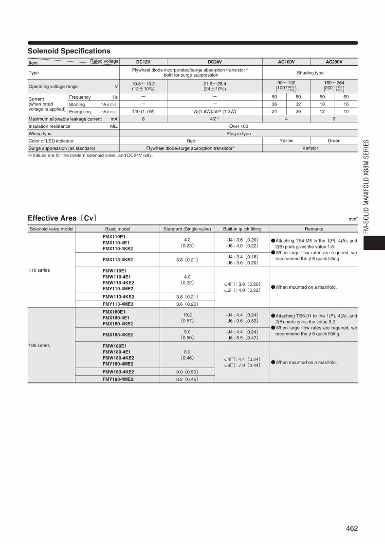
Varistor
Yellow Green
Solenoid SpecificationsRated voltageItem
Type
Operating voltage range V
Current(when ratedvoltage is applied)
Frequency
Starting mA (r.m.s)
Energizing mA (r.m.s)
Maximum allowable leakage current mA
Insulation resistance MΩWiring type
Color of LED indicator
Surge suppression (as standard)
DC12V
Flywheel diode incorporated/surge absorption transistor※, both for surge suppression Shading type
10.8~13.2(12±10%)
DC24V AC100V AC200V
21.6~26.4(24±10%)
-
-
140 (1.7W)
8
-
-
75(1.8W)/50※ (1.2W)
4/2※
90~132
(100+32% )-10%
180~264
(200+32% )-10%
50 60 50 60
36 32 18 16
24 20 12 10
4 2
Over 100
Plug-in type
Red
Flywheel diode/surge absorption transistor※
Effective Area〔Cv〕 mm2
Solenoid valve model
110 series
FMX110E1FMX110-4E1FMX110-4KE2
4.2〔0.23〕
3.8〔0.21〕
4.0〔0.22〕
3.8〔0.21〕
3.6〔0.20〕
-J4 : 3.6〔0.20〕-J6 : 4.0〔0.22〕
Attaching TS4-M5 to the 1(P), 4(A), and2(B) ports gives the value 1.8.When large flow rates are required, we
recommend theφ6 quick fitting.
When mounted on a manifold.
-J4 : 3.4〔0.18〕-J6 : 3.6〔0.20〕
-J4 : 3.6〔0.20〕-J6 : 4.0〔0.22〕
FMX113-4KE2
FMW110E1FMW110-4E1FMW110-4KE2FMY110-4ME2
FMW113-4KE2
FMY113-4ME2
Basic model Standard (Single valve) Built-in quick fitting Remarks
180 series
FMX180E1FMX180-4E1FMX180-4KE2
10.2〔0.57〕
9.0〔0.50〕
8.2〔0.46〕
9.0〔0.50〕
8.2〔0.46〕
-J4 : 4.4〔0.24〕-J6 : 9.6〔0.53〕
Attaching TS6-01 to the 1(P), 4(A), and2(B) ports gives the value 9.2.When large flow rates are required, we
recommend theφ6 quick fitting.
When mounted on a manifold.
-J4 : 4.4〔0.24〕-J6 : 8.5〔0.47〕
-J4 : 4.4〔0.24〕-J6 : 7.9〔0.44〕
FMX183-4KE2
FMW180E1FMW180-4E1FMW180-4KE2FMY180-4ME2
FMW183-4KE2
FMY183-4ME2
※Values are for the tandem solenoid valve, and DC24V only.
462
FM-S
OLID
MAN
IFOL
D X8
8M S
ERIE
S

Module Mass g [oz.] g [oz.]
Model Mass
FMX110E1
FMX110-4E1
FMX110-4KE2
FMX113-4KE2
FMX180E1
FMX180-4E1
FMX180-4KE2
FMX183-4KE2
110 [3.88]
110 [3.88]
230 [8.11]
230 [8.11]
150 [5.29]
150 [5.29]
310 [10.93]
310 [10.93]
Model
FMW110E1
FMW110-4E1
FMW110-4KE2
FMW113-4KE2
FMY110-4ME2
FMY113-4ME2
FMW180E1
FMW180-4E1
FMW180-4KE2
FMW183-4KE2
FMY180-4ME2
FMY183-4ME2
Bodymass
110 [3.88]
110 [3.88]
230 [8.11]
230 [8.11]
140 [4.94]
150 [5.29]
150 [5.29]
150 [5.29]
310 [10.93]
310 [10.93]
175 [6.17]
190 [6.70]
Mass with quick fitting added
-J4S -J6S -J4U -J6U -M8M
122 [4.30]
122 [4.30]
254 [8.96]
254 [8.96]
152 [5.36]
162 [5.71]
162 [5.71]
162 [5.71]
334 [11.78]
334 [11.78]
187 [6.60]
202 [7.13]
118 [4.16]
118 [4.16]
246 [8.68]
246 [8.68]
148 [5.22]
158 [5.57]
158 [5.57]
158 [5.57]
326 [11.50]
326 [11.50]
183 [6.46]
198 [6.98]
132 [4.66]
132 [4.66]
274 [9.66]
274 [9.66]
162 [5.71]
-
172 [6.07]
172 [6.07]
354 [12.49]
354 [12.49]
197 [6.95]
-
134 [4.73]
134 [4.73]
278 [9.81]
278 [9.81]
164 [5.78]
-
174 [6.14]
174 [6.14]
358 [12.63]
358 [12.63]
199 [7.02]
-
122 [4.30]
122 [4.30]
254 [8.96]
254 [8.96]
152 [5.36]
162 [5.71]
162 [5.71]
162 [5.71]
334 [11.78]
334 [11.78]
187 [6.60]
202 [7.13]
463

Cylinder Operating Speed
How to obtain cylinder speedTo obtain the time required for the cylinder tocomplete 1 stroke, add cylinder’s delay time t1
(time between energizing of the solenoid valveand actual starting of the cylinder), to thecylinder’s max. speed operating time t2.When a cushion is used, add the cushioning timet3, to the above calculation. The standardcushioning time t3 is approximately 0.2 seconds.
FMX110-4E1FMX110-4KE2FMX113-4KE2
FMW110-4E1FMW110-4KE2FMW113-4KE2FMY110-4ME2FMY113-4ME2
FMX180-4E1FMX180-4KE2FMX183-4KE2
FMW180-4E1FMW180-4KE2FMW183-4KE2FMY180-4ME2FMY183-4ME2
10 20 30 40 50 60 70
φ20φ25φ32φ40
%
mm/s 1200
1000
800
600
400
200
0
φ40φ32φ25φ20
10 20 30 40 50 60 70%
1.00.90.80.70.60.50.40.30.20.1
0
s
Load ratio
1mm/s = 0.0394in./sec.
Max
imum
ope
ratin
g sp
eed
Load ratio
Del
ay ti
me
mm/s 1200
1000
800
600
400
200
0
φ50φ40φ32φ25φ20
10 20 30 40 50 60 70%
φ20φ25φ32φ40
10 20 30 40 50 60 70%
1.00.90.80.70.60.50.40.30.20.1
0
s
Max
imum
ope
ratin
g sp
eed
Load ratioLoad ratio
Del
ay ti
me
1mm/s = 0.0394in./sec.
mm/s 1200
1000
800
600
400
200
0
φ80φ63φ50φ40
10 20 30 40 50 60 70%
φ40φ50φ63φ80
10 20 30 40 50 60 70%
1.00.90.80.70.60.50.40.30.20.1
0
s
Max
imum
ope
ratin
g sp
eed
Load ratioLoad ratio
Del
ay ti
me
1mm/s = 0.0394in./sec.
mm/s 1200
1000
800
600
400
200
0
φ63φ50φ40
10 20 30 40 50 60 70%
φ40φ50φ63φ80
10 20 30 40 50 60 70%
0.1
1.00.90.80.70.60.50.40.30.2
0
s
φ80
Max
imum
ope
ratin
g sp
eed
Load ratioLoad ratio
Del
ay ti
me
1mm/s = 0.0394in./sec.
t1 t2 t3 Time
Cyl
inde
rst
op
Cyl
inde
rst
art
Sole
noid
val
veen
ergi
zed
Cus
hion
ing
impa
ct
Cyl
inde
r st
roke
464
FM-S
OLID
MAN
IFOL
D X8
8M S
ERIE
SSolenoid Valves 110 Series
Measurement conditionsAir pressure: 0.5MPa 5.1kgf/cm2 [73psi.]Piping inner diameter and length:φ2.5 [0.10in.]×1000mm [39in.]Fitting: Quick fitting TS4-M5
Load ratio=Load
Cylinder theoretical thrust(%)
Cylinder stroke: 150mm [5.91in.]
Maximum operating speed Delay time
0.5MPa
Load
Cyl
inde
r
Measurement conditionsAir pressure: 0.5MPa 5.1kgf/cm2 [73psi.]Piping inner diameter and length:φ4 [0.16in.]×1000mm [39in.]Fitting: Quick fitting (-J6S)
Load ratio=Load
Cylinder theoretical thrust(%)
Cylinder stroke: 150mm [5.91in.]
Maximum operating speed Delay time
0.5MPa
Load
Cyl
inde
r
Solenoid Valves 180 Series
Measurement conditionsAir pressure: 0.5MPa 5.1kgf/cm2 [73psi.]Piping inner diameter and length:φ6 [0.24in.]×1000mm [39in.]Fitting: Quick fitting TS8-01
Load ratio=Load
Cylinder theoretical thrust(%)
Cylinder stroke: 300mm [11.81in.]
Maximum operating speed Delay time
0.5MPa
Load
Cyl
inde
r
Measurement conditionsAir pressure: 0.5MPa 5.1kgf/cm2 [73psi.]Piping inner diameter and length:φ4 [0.16in.]×1000mm [39in.]Fitting: Quick fitting (-J6S)
Load ratio=Load
Cylinder theoretical thrust(%)
Cylinder stroke: 300mm [11.81in.]
Maximum operating speed Delay time
0.5MPa
LoadC
ylin
der
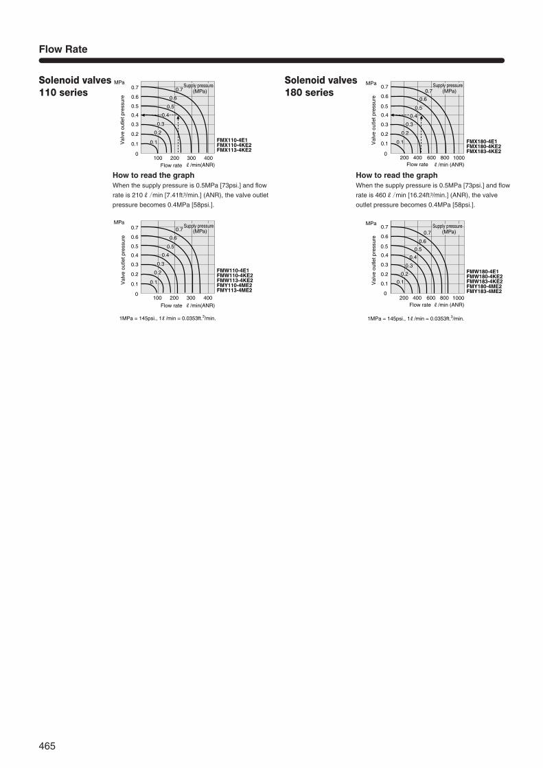
Flow Rate
Solenoid valves110 series
Solenoid valves180 series
0.7
0.6
0.5
0.4
0.3
0.2
0.1
0
MPa
0.7
0.6
0.5
0.4
0.3
0.2
0.1
0
MPa
200 400 600 800R/min (ANR)
1000
200 400 600 800R/min (ANR)
1000
FMX180-4E1FMX180-4KE2FMX183-4KE2
FMW180-4E1FMW180-4KE2FMW183-4KE2FMY180-4ME2FMY183-4ME2
0.6
0.7
0.5
0.4
0.3
0.2
0.1
0.6
0.7
0.5
0.4
0.3
0.2
0.1
Val
ve o
utle
t pre
ssur
eV
alve
out
let p
ress
ure
Flow rate
Flow rate
1MPa = 145psi., 1R/min = 0.0353ft.3/min.
(MPa)Supply pressure
(MPa)Supply pressure
How to read the graphWhen the supply pressure is 0.5MPa [73psi.] and flow
rate is 210R/min [7.41ft.3/min.] (ANR), the valve outlet
pressure becomes 0.4MPa [58psi.].
How to read the graphWhen the supply pressure is 0.5MPa [73psi.] and flow
rate is 460R/min [16.24ft.3/min.] (ANR), the valve
outlet pressure becomes 0.4MPa [58psi.].
(MPa)0.7
0.6
0.5
0.4
0.3
0.2
0.1
R/min(ANR)
0.7
0.6
0.5
0.4
0.3
0.2
0.1
0100 200 300 400
MPa
(MPa)0.7
0.6
0.5
0.4
0.3
0.2
0.1
R/min(ANR)
0.7
0.6
0.5
0.4
0.3
0.2
0.1
0100 200 300 400
MPa
FMX110-4E1FMX110-4KE2FMX113-4KE2
FMW110-4E1FMW110-4KE2FMW113-4KE2FMY110-4ME2FMY113-4ME2
Val
ve o
utle
t pre
ssur
eV
alve
out
let p
ress
ure
Flow rate
Flow rate
1MPa = 145psi., 1R/min = 0.0353ft.3/min.
Supply pressure
Supply pressure
465
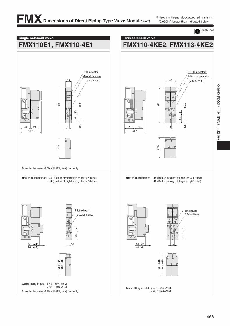
FMX Dimensions of Direct Piping Type Valve Module (mm)
Single solenoid valve
FMX110E1, FMX110-4E1Twin solenoid valve
FMX110-4KE2, FMX113-4KE2
※Height with end block attached is +1mm[0.039in.] longer than indicated below.
Note: In the case of FMX110E1, 4(A) port only.
With quick fittings: -J4 (Built-in straight fittings for φ4 tube)-J6 (Built-in straight fittings for φ6 tube)
With quick fittings: -J4 (Built-in straight fittings for φ4 tube)-J6 (Built-in straight fittings for φ6 tube)
Quick fitting model φ4 : TSK4-M8Mφ6 : TSK6-M8M
Note: In the case of FMX110E1, 4(A) port only.Quick fitting model φ4 : TSK4-M8M
φ6 : TSK6-M8M
28 6
16
24
57.5
57.5
98
2510
8.5
80.9
2-M5×0.8
4(A)
2(B)
LED indicator
Manual override
28 24
57.5
32
2-LED indicators
2-Manual overrides
2-M5×0.8
6
10
80.9
8.5
9857
.5
25
4(A)
2(B)
3.69.1(-J4)9.8(-J6)
61.1(
-J4)
61.8(
-J6)
2510
4(A)
2(B)
Pilot exhaust
2-Quick fittings
9.1 (-J4)9.8 (-J6)
61.8
(-J
6)
61.1
(-J
4)
12.4
2510
2(B)
4(A)
2-Pilot exhausts
2-Quick fittings
X88M-FX1
466
FM-S
OLID
MAN
IFOL
D X8
8M S
ERIE
S
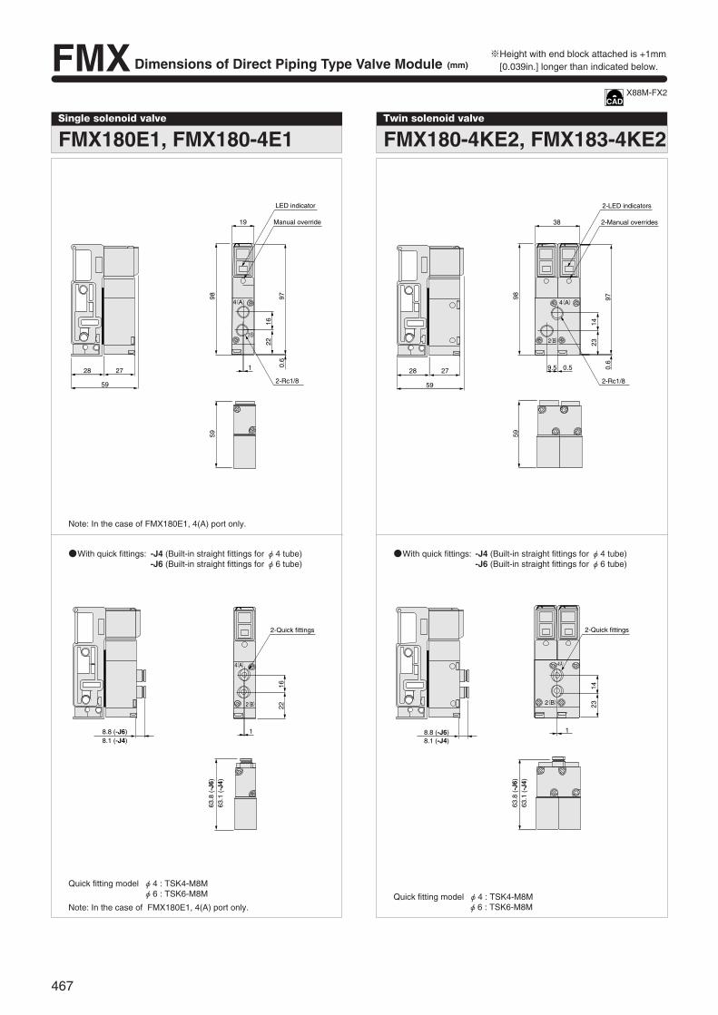
※Height with end block attached is +1mm[0.039in.] longer than indicated below.
Single solenoid valve
FMX180E1, FMX180-4E1Twin solenoid valve
FMX180-4KE2, FMX183-4KE2
Note: In the case of FMX180E1, 4(A) port only.
With quick fittings: -J4 (Built-in straight fittings for φ4 tube)-J6 (Built-in straight fittings for φ6 tube)
With quick fittings: -J4 (Built-in straight fittings for φ4 tube)-J6 (Built-in straight fittings for φ6 tube)
Quick fitting model φ4 : TSK4-M8Mφ6 : TSK6-M8M
Note: In the case of FMX180E1, 4(A) port only.Quick fitting model φ4 : TSK4-M8M
φ6 : TSK6-M8M
28 27
59
19
98 97
1622
0.6
2-Rc1/8
59
1
4(A)
2(B)
LED indicator
Manual override
8.8 (-J6)8.1 (-J4)
1622
1
63.8
(-J
6)63
.1 (
-J4)
4(A)
2(B)
2-Quick fittings
1423
1
4(A)
2(B)
8.8 (-J6)8.1 (-J4)
2-Quick fittings
63.8
(-J
6)63
.1 (
-J4)
28 27
59
38
98 97
1423
0.6
2-Rc1/8
59
9.5 0.5
4(A)
2(B)
2-LED indicators
2-Manual overrides
X88M-FX2
FMX Dimensions of Direct Piping Type Valve Module (mm)
467

FMW Dimensions of Base Piping Type Valve Module (mm)
Single solenoid valve
FMW110E1, FMW110-4E1
28 24
57.5
16
982
80.9
8.5
2-M8×0.75
57.5
127.
5
2
A
LED indicator
Manual override
2(B)Port
4(A)Port
※Height with end block attached is +1mm[0.039in.] longer than indicated below.
Note: For FMW110E1, the 2(B) port is plugged, while for FMW110E1-11, the 4(A) port is plugged (φ4: UP-4, φ6: UP-6).
Note: For FMW110E1, the 2(B) port is plugged, while for FMW110E1-11, the 4(A) port is plugged (M8: PF-M8M).
With elbow quick fittings: -J4U (Built-in elbow fittings for φ4 tube)-J6U (Built-in elbow fittings for φ6 tube)
Note: For FMW110E1, the 2(B) port is plugged, while for FMW110E1-11, the 4(A) port is plugged (φ4: UP-4, φ6: UP-6).
M8 female thread type: -M8MWith quick fittings: -J4S (Built-in straight fittings for φ4 tube)-J6S (Built-in straight fittings for φ6 tube)
28 24
57.5
16
983.
4
80.9
8.5
57.5
127.
7
2
LED indicator
Manual override
2-Quick fittings
2(B)Port
4(A)Port
B
A
57.5
2
2-Quick fittings
2(B)Port
4(A)Port
15.2(-J4U)16.25(-J6U)
20.4(
-J4U)
24.4(
-J6U)
5.5(
-J4U)
6.5(
-J6U)
15.5(
-J4U)
18.5(
-J6U)
X88M-FW1
468
FM-S
OLID
MAN
IFOL
D X8
8M S
ERIE
S
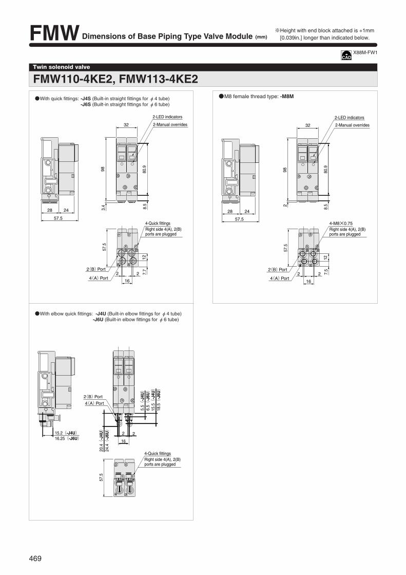
Twin solenoid valve
FMW110-4KE2, FMW113-4KE2
※Height with end block attached is +1mm[0.039in.] longer than indicated below.
With elbow quick fittings: -J4U (Built-in elbow fittings for φ4 tube)-J6U (Built-in elbow fittings for φ6 tube)
M8 female thread type: -M8MWith quick fittings: -J4S (Built-in straight fittings for φ4 tube)-J6S (Built-in straight fittings for φ6 tube)
28 24
57.5
32
98 80.9
3.4 8.5
57.5
2
16
2
127.
7
AA
B B
2-LED indicators
2-Manual overrides
4-Quick fittingsRight side 4(A), 2(B) ports are plugged
2(B)Port
4(A)Port
BB
AA
15.2(-J4U)16.25(-J6U)
2 2
16
57.5
20.4(
-J4U)
24.4(
-J6U)
5.5(
-J4U)
6.5(
-J6U)
15.5(
-J4U)
18.5(
-J6U)
4-Quick fittingsRight side 4(A), 2(B) ports are plugged
2(B)Port
4(A)Port
A
B
A
B
28 24
57.5
32
98 80.9
8.52
57.5
2 2
127.
5
16
2-LED indicators
2-Manual overrides
4-M8×0.75Right side 4(A), 2(B) ports are plugged
2(B)Port
4(A)Port
X88M-FW1
FMW Dimensions of Base Piping Type Valve Module (mm)
469
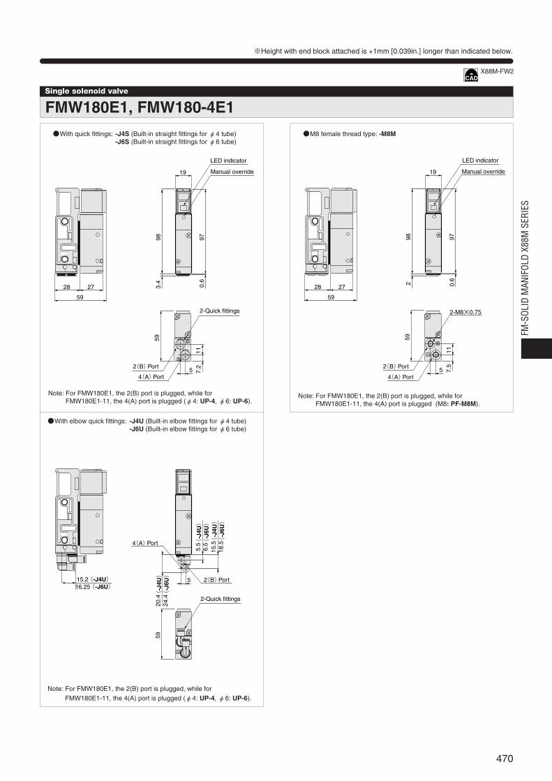
Single solenoid valve
FMW180E1, FMW180-4E1With quick fittings: -J4S (Built-in straight fittings for φ4 tube)
-J6S (Built-in straight fittings for φ6 tube)M8 female thread type: -M8M
※Height with end block attached is +1mm [0.039in.] longer than indicated below.
Note: For FMW180E1, the 2(B) port is plugged, while for FMW180E1-11, the 4(A) port is plugged (φ4: UP-4, φ6: UP-6).
Note: For FMW180E1, the 2(B) port is plugged, while for FMW180E1-11, the 4(A) port is plugged (M8: PF-M8M).
With elbow quick fittings: -J4U (Built-in elbow fittings for φ4 tube)-J6U (Built-in elbow fittings for φ6 tube)
Note: For FMW180E1, the 2(B) port is plugged, while for FMW180E1-11, the 4(A) port is plugged (φ4: UP-4, φ6: UP-6).
A
B
28 27
5
19
9859
117.
2
3.4
0.6
97
59
LED indicator
Manual override
2-Quick fittings
2(B)Port
4(A)Port
A
B
15.2 5
5.5
6.5
15.5
18.5(
-J4U)
(-J
6U)
(-J
4U)
(-J
6U)
20.4
24.4(
-J4U)
(-J
6U)
59
16.25(-J4U) (-J6U)
2-Quick fittings
2(B)Port
4(A)Port
A
B
28 27
59
19
982 0.
697
5
2-M8×0.75
59
117.
5
Manual override
LED indicator
2(B)Port
4(A)Port
X88M-FW2
470
FM-S
OLID
MAN
IFOL
D X8
8M S
ERIE
S

※Height with end block attached is +1mm[0.039in.] longer than indicated below.
With elbow quick fittings: -J4U (Built-in elbow fittings for φ4 tube)-J6U (Built-in elbow fittings for φ6 tube)
Twin solenoid valve
FMW180-4KE2,FMW183-4KE2
With quick fittings: -J4S (Built-in straight fittings for φ4 tube)-J6S (Built-in straight fittings for φ6 tube)
M8 female thread type: -M8M
28 27
59
195 5
38
9859
11
3.4
7.2
0.6
97
A A
B B
2-LED indicators
2-Manual overrides
4-Quick fittings Right side 4(A), 2(B) ports are plugged
2(B)Port
4(A)Port
28 27
59
195 5
38
982
59
117.
50.
697
A A
B B
2-LED indicators
2-Manual overrides
4-M8×0.75Right side 4(A), 2(B) ports are plugged
2(B)Port
4(A)Port
15.2(-J4U) 5 5
19
6.5(
-J6U)
5.5(
-J4U)
24.4(
-J6U)
20.4(
-J4U)
59
18.5(
-J6U)
15.5(
-J4U)
16.25(-J6U)
A A
B B
4-Quick fittingsRight side 4(A), 2(B) ports are plugged
2(B)Port
4(A)Port
X88M-FW2
FMW Dimensions of Base Piping Type Valve Module (mm)
471

FMY Dimensions of Base Piping Type Valve Module (mm)
Tandem solenoid valve
FMY110-4ME2
※Height with end block attached is +1mm[0.039in.] longer than indicated below.
With elbow quick fittings: -J4U (Built-in elbow fittings for φ4 tube)-J6U (Built-in elbow fittings for φ6 tube)
With quick fittings: -J4S (Built-in straight fittings for φ4 tube)-J6S (Built-in straight fittings for φ6 tube)
M8 female thread type: -M8M
KSA3261Z.EPS
28 30
62
16
8.5
3.4
98 84.5
62
127.
5
2
A
A B
A B
B
DC24V
A
B
2-LED indicators
Manual override
2-Quick fittings
2(B)Port
4(A)Port
28 30
62
16
8.52
98 84.5
62
127.
5
2-M8×0.75
2
A
A B
A B
B
DC24V
A
B
2-LED indicators
Manual override
2(B)Port
4(A)Port
15.2(-J4U)16.25(-J6U)
20.4(
-J4U)
24.4(
-J6U)
5.5(
-J4U)
6.5(
-J6U)
15.5(
-J4U)
18.5(
-J6U)
2
62
A
A B
A B
BDC24V
A
B
2-Quick fittings
2(B) Port
4(A)Port
X88MY110
472
FM-S
OLID
MAN
IFOL
D X8
8M S
ERIE
S
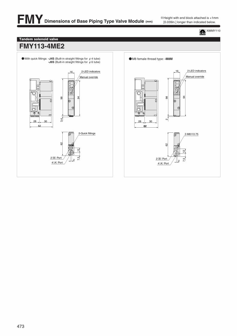
28 30
62
98
62
94
2
16
2-M8×0.75
62
127.
5
2
A
B
DC24V
A B
A B
A
B
2-LED indicators
Manual override
2(B)Port
4(A)Port
※Height with end block attached is +1mm[0.039in.] longer than indicated below.
Tandem solenoid valve
FMY113-4ME2
With quick fittings: -J4S (Built-in straight fittings for φ4 tube)-J6S (Built-in straight fittings for φ6 tube)
M8 female thread type: -M8M
28 30
62
16
98 94
3.4
62
7.5
12
2
A
B
DC24V
A B
A B
A
B
2-LED indicators
Manual override
2-Quick fittings
2(B)Port
4(A)Port
X88MY110
FMY Dimensions of Base Piping Type Valve Module (mm)
473

Tandem solenoid valve
FMY180-4ME2
※Height with end block attached is +1mm [0.039in.] longer than indicated below.
With quick fittings: -J4S (Built-in straight fittings for φ4 tube)-J6S (Built-in straight fittings for φ6 tube)
M8 female thread type: -M8M
With elbow quick fittings: -J4U (Built-in elbow fittings for φ4 tube)-J6U (Built-in elbow fittings for φ6 tube)
A
B
A
A
B
B
DC24V
A B
28 30
62
19
98 100.
6
3.4 0.6
711
5
62
2-LED indicators
Manual override
2-Quick fittings
2(B)Port
4(A)Port
A
B
A
A
B
B
DC24V
A B
28 30
62
19
98 100.
6
2 0.6
2-M8×0.75
711
5
62
2-LED indicators
Manual override
2(B)Port
4(A)Port
A
B
A
A
B
B
DC24V
A B
15.2(-J4U)16.25(-J6U)
20.4(
-J4U)
24.4(
-J6U)
5.5(
-J4U)
6.5(
-J6U)
15.5(
-J4U)
18.5(
-J6U)
5
62
2-Quick fittings
2(B)Port
4(A)Port
X88MY180
474
FM-S
OLID
MAN
IFOL
D X8
8M S
ERIE
S

A
B
A
A
B
B
DC24V
A B
2-M8×0.75
5
62
711
11.6
98
112.
8
19
28 30
622
Manual override
2-LED indicators
2(B)Port
4(A)Port
A
B
A
A
B
B
DC24V
A B
3.
4(
-J4S
,-J6
S)
5
62
711
11.6
98
112.
8
19
28 30
622-Quick fittings
Manual override
2-LED indicators
2(B)Port
4(A)Port
Tandem solenoid valve
FMY183-4ME2
With quick fittings: -J4S (Built-in straight fittings for φ4 tube)-J6S (Built-in straight fittings for φ6 tube)
M8 female thread type: -M8M
※Height with end block attached is +1mm[0.039in.] longer than indicated below.
X88MY180
FMY Dimensions of Base Piping Type Valve Module (mm)
475
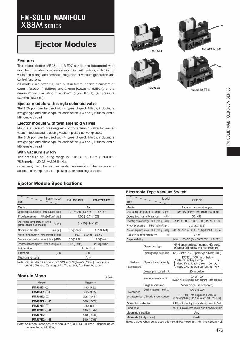
Operation indicator
Lead wire
Mounting direction
Materials (Body cover)
Vibration resistance
Surge suppression
Shock resistance m/s2 G
Consumption current mA
Operating voltage range DC V
Ejector Modules
FeaturesThe micro ejector ME05 and ME07 series are integrated with
modules to enable combination mounting with valves, collecting of
wires and piping, and compact integration of vacuum generation and
control functions.
All models are powerful, with built-in filters, nozzle diameters of
0.5mm [0.020in.] (ME05) and 0.7mm [0.028in.] (ME07), and a
maximum vacuum rating of –650mmHg [–25.6in.Hg] (air pressure
86.7kPa [12.6psi.]).
Ejector module with single solenoid valveThe 2(B) port can be used with 4 types of quick fittings, including a
straight type and elbow type for each of the φ4 and φ6 tubes, and a
M8 female thread.
Ejector module with twin solenoid valvesMounts a vacuum breaking air control solenoid valve for easier
vacuum breaks and releasing vacuum picked up workpieces.
The 2(B) port can be used with 4 types of quick fittings, including a
straight type and elbow type for each of the φ4 and φ6 tubes, and a
M8 female thread.
With vacuum switch The pressure adjusting range is –101.3~10.1kPa –760.0~75.8mmHg [–29.921~2.984in.Hg].
Offers easy control of vacuum levels, confirmation of the presence or
absence of workpieces, and picking up or releasing of them.
Ejector Module Specifications
FMJ05E1
FMJ05E2
FMJ07E1--E
FMJ05E2--E
Module Mass g [oz.]
Model MassNote
FMJ05E1- 165 [5.82]
FMJ05E1--E 265 [9.35]
FMJ05E2- 295 [10.41]
FMJ05E2--E 390 [13.76]
FMJ07E1- 230 [8.11]
FMJ07E1--E 330 [11.64]
FMJ07E2- 410 [14.46]
FMJ07E2--E 510 [17.99]
Note: Additional mass can vary from 4 to 12g [0.14~0.42oz.], depending onthe selected quick fitting.
Note: Values when set pressure is –86.7KPa –650.3mmHg [–25.602in.Hg].
Note: Values when air pressure 0.5MPa 5.1kgf/cm2 [73psi.]. For details,see the General Catalog of Air Treatment, Auxiliary, Vacuum.
ModelItem PS310E
Air or non-corrosive gas
–10~60 [14~140] (non freezing)
35~95
–101.3~0 (–760.0~0) [–29.921~0]
0.2 2.0 [29]
–101.3~10.1 (–760.0~75.8) [–29.921~2.984]
2~9
Max.±3%FS (0~50°C [32~122°F])
Electrical
specifications
Mechanical
characteristics
Operation type NPN open collector output, NO type. (Output ON below the set pressure)
12~24±10% (Ripple Vp-p Max.10%)
Open/close capacity
20 or below
Zener diode (as standard)
490.3 50.0
10~55Hz (Total amplitude 1.5mm) or 98.1m/s2 10.0G (XYZ axis each MAX.2 hours)
LED indicator lights up when power is ON
PVC 0.14SQ×3 leads (Black, blue, brown)×500mm
Any
Plastic
Insulation resistance MΩ Over 100(DC500V megger, between every charging portion and case)
Basic modelItem FMJ05E1/E2
Media
Operating pressure range MPa kgf/cm2 [psi.]
Proof pressure MPa kgf/cm2 [psi.]
Air
0.1~0.6 1.0~6.1 [15~87]
1.05 10.7 [152]
Operating temperature range(atmosphere and media) °C [°F] 5~50 [41~122]
Nozzle diameter mm [in.]
Maximum vacuumNote KPa mmHg [in.Hg]
Flow rate of vacuumNote R/min [ft.3/min.] (ANR)
Compressed air consumptionNote R/min [ft.3/min.] (ANR)
Lubrication
Filtration μm
Mounting direction
0.5 [0.020]
–86.7 –650.3 [–25.60]
6.3 [0.222]
11.5 [0.406]
Prohibited
30
Any
12.5 [0.441]
23.0 [0.812]
0.7 [0.028]
FMJ07E1/E2
Electronic Type Vacuum Switch
Media
Operating temperature range °C [°F]
Operating humidity range %RH
Operating pressure range KPa mmHg [in.Hg]
Proof pressure MPa kgf/cm2 [psi.]
Pressure adjusting range KPa mmHg [in.Hg]
Response differentialNote %
Repeatability
476
FM-S
OLID
MAN
IFOL
D X8
8M S
ERIE
S
SERIESFM-SOLID MANIFOLD
DC30V, 100mA or belowInternal voltage drop:Max. 1V at load current 100mA,Max. 0.4V at load current 16mA( )

B
A
77
127.
5
2
16 16
80.998
2 8.5
28
77
M8×0.75
Exhaust port
Filter
Solenoid for supply air control
LED indicator
Manual override
Vacuum switch(PS310E):-E
※Height with end block attached is +1mm[0.039in.] longer than indicated below.FMJ Dimensions of Ejector Module (mm)
Ejector with single solenoid valve
FMJ05E1
With quick fitting: -J4S (Built-in straight fitting for φ4 tube)-J6S (Built-in straight fitting for φ6 tube)
M8 female thread type: -M8M
With elbow quick fitting: -J4U (Built-in elbow fitting for φ4 tube)-J6U (Built-in elbow fitting for φ6 tube)
B
A
77
15.2(-J4U)16.25(-J6U)
10.4(
-J4U)
12.4(
-J6U)
5.5(
-J4U)
6.5(
-J6U)
Exhaust port
Quick fitting 2(B):Vacuum generation port
B
A
77
19.5
1
16 16
80.9
983.
4
8.5
28
77
Solenoid for supply air control
LED indicator
Manual override
Vacuum switch(PS310E):-E
Exhaust port
Filter
Quick fitting 2(B): Vacuum generation port
X88M-J05
477
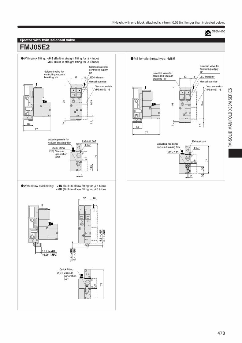
Ejector with twin solenoid valve
FMJ05E2
※Height with end block attached is +1mm [0.039in.] longer than indicated below.
With quick fitting: -J4S (Built-in straight fitting for φ4 tube)-J6S (Built-in straight fitting for φ6 tube)
M8 female thread type: -M8M
With elbow quick fitting: -J4U (Built-in elbow fitting for φ4 tube)-J6U (Built-in elbow fitting for φ6 tube)
B
A
32 16
77
15.2(-J4U)16.25(-J6U)
10.4(
-J4U)
12.4(
-J6U)
5.5(
-J4U)
6.5(
-J6U)
Quick fitting2(B): Vaccum generation port
B
A
28
77
983.
4
8.5
80.9
32 16
77
1
19.5
Solenoid valve for controlling supplyair
LED indicator
Manual override
Vacuum switch(PS310E):-E
Quick fitting2(B): Vacuum generation port
Exhaust port
Filter
Solenoid valve for controlling vacuum breaking air
Adjusting needle forvacuum breaking flow
B
A
28
77
982 8.5
80.9
32 16
77
2
12
M8×0.75
7.5
LED indicator
Manual override
Vacuum switch(PS310E):-E
Exhaust port
Filter
Adjusting needle forvacuum breaking flow
Solenoid valve for controlling supplyair Solenoid valve for
controlling vacuum breaking air
X88M-J05
478
FM-S
OLID
MAN
IFOL
D X8
8M S
ERIE
S
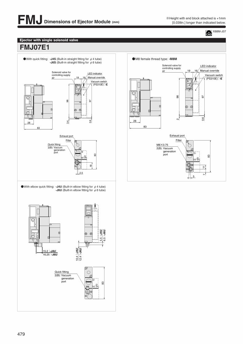
B
A
28
83
982 0.6
97
19 16
83
5
117
Solenoid valve for controlling supplyair
LED indicator
Manual override
Vacuum switch (PS310E):-E
M8×0.752(B): Vacuum generation port
Exhaust port
Filter
※Height with end block attached is +1mm[0.039in.] longer than indicated below.
Ejector with single solenoid valve
FMJ07E1
With quick fitting: -J4S (Built-in straight fitting for φ4 tube)-J6S (Built-in straight fitting for φ6 tube)
With elbow quick fitting: -J4U (Built-in elbow fitting for φ4 tube)-J6U (Built-in elbow fitting for φ6 tube)
M8 female thread type: -M8M
10.4(
-J4U)
12.4(
-J6U)
B
A
83
15.2(-J4U)16.25(-J6U)
5.5(
-J4U)
6.5(
-J6U)
Quick fitting2(B): Vacuum generation port
B
A
28
83
983.
4 0.6
97
19 16
83
2.5
18
Solenoid valve for controlling supplyair
LED indicator
Manual override
Vacuum switch (PS310E):-E
Quick fitting2(B): Vaccum generation port
Exhaust port
Filter
X88M-J07
FMJ Dimensions of Ejector Module (mm)
479

Ejector with twin solenoid valve
FMJ07E2
※Height with end block attached is +1mm [0.039in.] longer than indicated below.
With quick fitting: -J4S (Built-in straight fitting for φ4 tube)-J6S (Built-in straight fitting for φ6 tube)
With elbow quick fitting: -J4U (Built-in elbow fitting for φ4 tube)-J6U (Built-in elbow fitting for φ6 tube)
M8 female thread type: -M8M
15.2(-J4U)
10.4(
-J4U)
12.4(
-J6U)
16.25(-J6U)
5.5(
-J4U)
6.5(
-J6U)
83
A
B
Quick fitting 2(B): Vacuum generation port
28
83
Filter
2.5
38 16
97983.
4 0.6
18
83
Quick fitting2(B): Vacuum generation port
Exhaust port
Solenoid valve for controlling supplyair
LED indicator
Manual override
Vacuum switch(PS310E): -E
Solenoid valve for controlling vacuum breaking air
Adjusting needle forvacuum breaking flow
28
38 16
M8×0.75
5
83
97982 0.
611
7
83
A
B
LED indicator
Manual override
Vacuum switch(PS310E): -E
Exhaust port
Filter
Adjusting needle forvacuum breaking flow
Solenoid valve for controlling supplyair Solenoid valve for
controlling vacuum breaking air
X88M-J07
480
FM-S
OLID
MAN
IFOL
D X8
8M S
ERIE
S
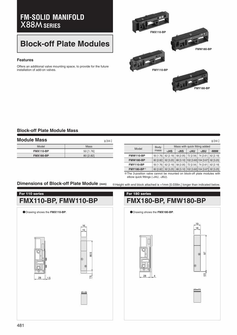
Block-off Plate Modules
Features
Offers an additional valve mounting space, to provide for the futureinstallation of add-on valves.
Block-off Plate Module Mass
Dimensions of Block-off Plate Module (mm)
FMX110-BP
FMW180-BP
FMY110-BP
FMY180-BP
For 110 series
FMX110-BP, FMW110-BP
28 1.5
16
15
80.5
7.5
Drawing shows the FMX110-BP.
For 180 series
FMX180-BP, FMW180-BP
28 4
19
18
970.5
Drawing shows the FMX180-BP.
※Height with end block attached is +1mm [0.039in.] longer than indicated below.
Module Mass g [oz.] g [oz.]
Model Mass
FMX110-BP
FMX180-BP
50 [1.76]
80 [2.82]
Model
FMW110-BP
FMW180-BP
FMY110-BP
FMY180-BP※
Bodymass
50 [1.76] 62 [2.19] 58 [2.05] 72 [2.54] 74 [2.61] 62 [2.19]
80 [2.82] 92 [3.25] 88 [3.10] 102 [3.60] 104 [3.67] 92 [3.25]
50 [1.76] 62 [2.19] 58 [2.05] 72 [2.54] 74 [2.61] 62 [2.19]
80 [2.82] 92 [3.25] 88 [3.10] 102 [3.60] 104 [3.67] 92 [3.25]
Mass with quick fitting added
-J4S -J6S -J4U -J6U -M8M
※The 3-position valve cannot be mounted on block-off plate modules withelbow quick fittings (-J4U, -J6U).
481
SERIESFM-SOLID MANIFOLD
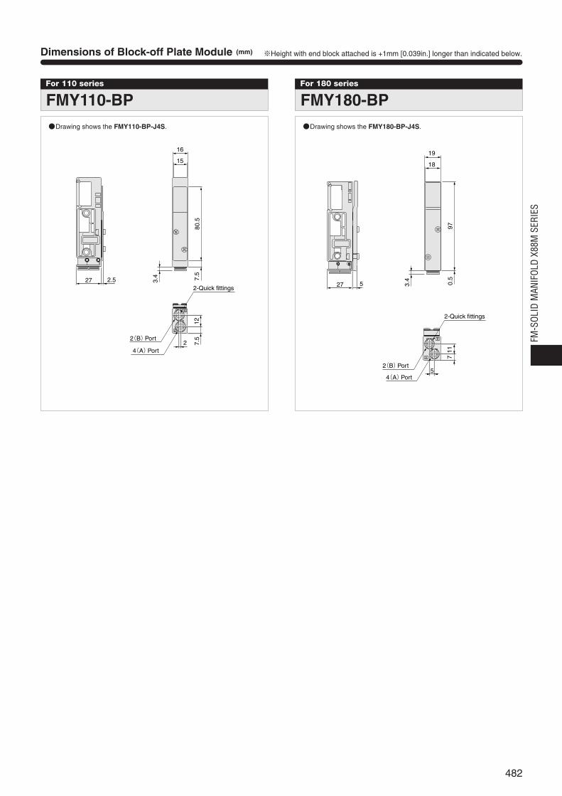
Dimensions of Block-off Plate Module (mm)
For 110 series
FMY110-BP
16
27 2.5
2
7.5
3.4
80.5
127.
5
15
B
A
2-Quick fittings
2(B)Port
4(A)Port
For 180 series
FMY180-BP
B
A
19
27 5
5
0.5
3.4
977
11
18
2-Quick fittings
2(B)Port
4(A)Port
※Height with end block attached is +1mm [0.039in.] longer than indicated below.
Drawing shows the FMY110-BP-J4S. Drawing shows the FMY180-BP-J4S.
482
FM-S
OLID
MAN
IFOL
D X8
8M S
ERIE
S
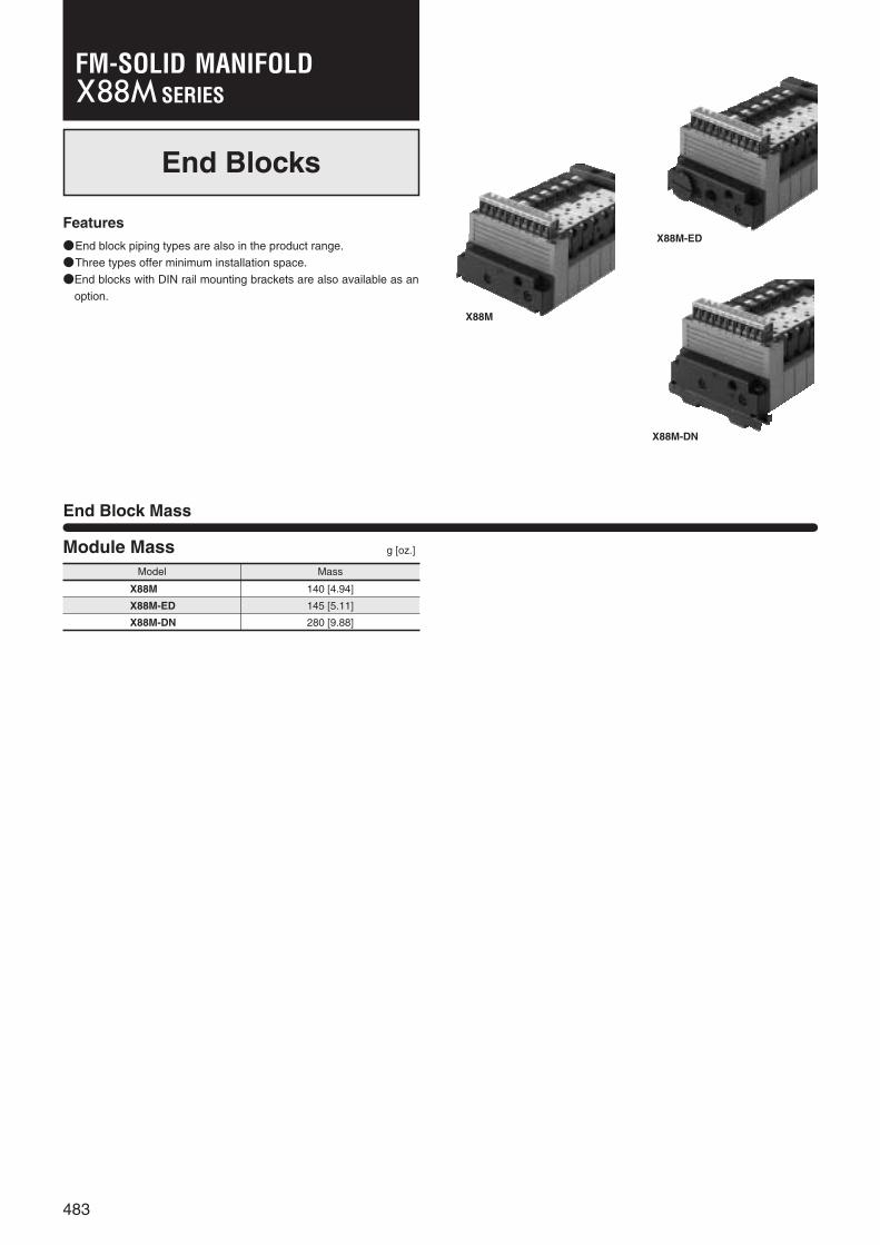
End Blocks
Features
End block piping types are also in the product range.
Three types offer minimum installation space.
End blocks with DIN rail mounting brackets are also available as an
option.
End Block Mass
X88M
X88M-ED
X88M-DN
Module Mass g [oz.]
Model Mass
X88M
X88M-ED
X88M-DN
140 [4.94]
145 [5.11]
280 [9.88]
483
SERIESFM-SOLID MANIFOLD
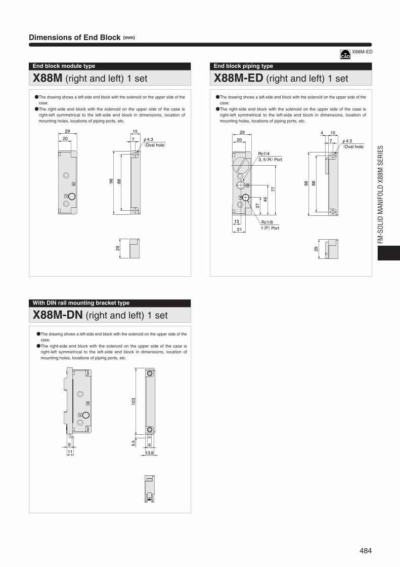
End block module type
X88M (right and left) 1 set
20
29
R
P
98 88
15
7
29
φ4.3(Oval hole)
End block piping type
X88M-ED (right and left) 1 set
20
29
R
P
98 88
15
7
29
13
21
Rc1/4
27
46
77
Rc1/8
4
φ4.3(Oval hole)
3, 5(R)Port
1(P)Port
With DIN rail mounting bracket type
X88M-DN (right and left) 1 set
103
5.5
6
13.9
9
11
R
P
Dimensions of End Block (mm)
The drawing shows a left-side end block with the solenoid on the upper side of thecase.The right-side end block with the solenoid on the upper side of the case is
right-left symmetrical to the left-side end block in dimensions, location ofmounting holes, locations of piping ports, etc.
The drawing shows a left-side end block with the solenoid on the upper side of thecase.The right-side end block with the solenoid on the upper side of the case is
right-left symmetrical to the left-side end block in dimensions, location ofmounting holes, locations of piping ports, etc.
The drawing shows a left-side end block with the solenoid on the upper side of thecase.The right-side end block with the solenoid on the upper side of the case is
right-left symmetrical to the left-side end block in dimensions, location ofmounting holes, locations of piping ports, etc.
X88M-ED
484
FM-S
OLID
MAN
IFOL
D X8
8M S
ERIE
S
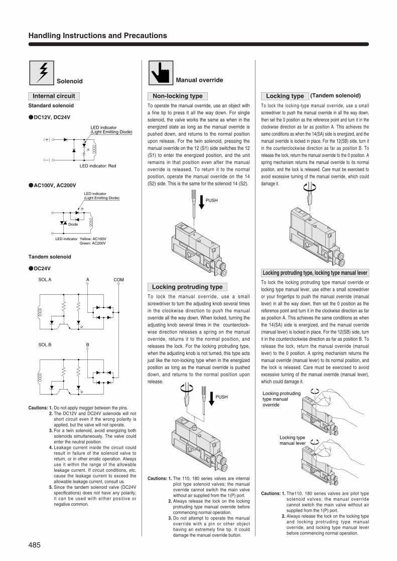
Handling Instructions and Precautions
Solenoid
Internal circuit
DC12V, DC24V
AC100V, AC200V
DC24V
Tandem solenoid
Standard solenoid
Manual override
Non-locking type
To operate the manual override, use an object witha fine tip to press it all the way down. For singlesolenoid, the valve works the same as when in theenergized state as long as the manual override ispushed down, and returns to the normal positionupon release. For the twin solenoid, pressing themanual override on the 12 (S1) side switches the 12(S1) to enter the energized position, and the unitremains in that position even after the manualoverride is released. To return it to the normalposition, operate the manual override on the 14(S2) side. This is the same for the solenoid 14 (S2).
Locking protruding type
To lock the manual override, use a smallscrewdriver to turn the adjusting knob several timesin the clockwise direction to push the manualoverride all the way down. When locked, turning theadjusting knob several times in the counterclock-wise direction releases a spring on the manualoverride, returns it to the normal position, andreleases the lock. For the locking protruding type,when the adjusting knob is not turned, this type actsjust like the non-locking type when in the energizedposition as long as the manual override is pusheddown, and returns to the normal position uponrelease.
Cautions: 1. The 110, 180 series valves are internalpilot type solenoid valves; the manualoverride cannot switch the main valvewithout air supplied from the 1(P) port.
2. Always release the lock on the lockingprotruding type manual override beforecommencing normal operation.
3. Do not attempt to operate the manualoverride with a pin or other objecthaving an extremely fine tip. It coulddamage the manual override button.
Locking type (Tandem solenoid)
To lock the locking-type manual override, use a smallscrewdriver to push the manual override in all the way down,then set the 0 position as the reference point and turn it in theclockwise direction as far as position A. This achieves thesame conditions as when the 14(SA) side is energized, and themanual override is locked in place. For the 12(SB) side, turn itin the counterclockwise direction as far as position B. Torelease the lock, return the manual override to the 0 position. Aspring mechanism returns the manual override to its normalposition, and the lock is released. Care must be exercised toavoid excessive turning of the manual override, which coulddamage it.
Locking protruding type, locking type manual lever
To lock the locking protruding type manual override orlocking type manual lever, use either a small screwdriveror your fingertips to push the manual override (manuallever) in all the way down, then set the 0 position as thereference point and turn it in the clockwise direction as faras position A. This achieves the same conditions as whenthe 14(SA) side is energized, and the manual override(manual lever) is locked in place. For the 12(SB) side, turnit in the counterclockwise direction as far as position B. Torelease the lock, return the manual override (manuallever) to the 0 position. A spring mechanism returns themanual override (manual lever) to its normal position, andthe lock is released. Care must be exercised to avoidexcessive turning of the manual override (manual lever),which could damage it.
Cautions: 1. Do not apply megger between the pins.2. The DC12V and DC24V solenoids will not
short circuit even if the wrong polarity isapplied, but the valve will not operate.
3. For a twin solenoid, avoid energizing bothsolenoids simultaneously. The valve couldenter the neutral position.
4. Leakage current inside the circuit couldresult in failure of the solenoid valve toreturn, or in other erratic operation. Alwaysuse it within the range of the allowableleakage current. If circuit conditions, etc.cause the leakage current to exceed theallowable leakage current, consult us.
5. Since the tandem solenoid valve (DC24Vspecifications) does not have any polarity,it can be used with either posit ive ornegative common.
Cautions: 1. The110, 180 series valves are pilot typesolenoid valves; the manual overridecannot switch the main valve without airsupplied from the 1(P) port.
2. Always release the lock on the locking typeand locking protruding type manualoverride, and locking type manual leverbefore commencing normal operation.
PUSH
PUSHLocking protrudingtype manual override
Locking type manual lever
(+)
(-)
LED indicator(Light Emitting Diode)
LED indicator: Red
Diode
LED indicator Yellow: AC100V Green: AC200V
LED indicator(Light Emitting Diode)
A COMSOL.A
BSOL.B
485
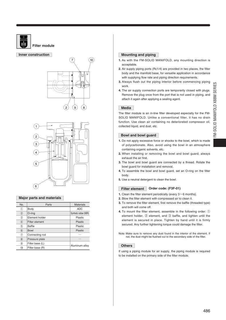
w
r
y
i
O-ring
Filter element
Bowl
Pressure plate
Synthetic rubber (NBR)
Plastic
Plastic
Filter module
Inner construction
Major parts and materials
Mounting and piping
1. As with the FM-SOLID MANIFOLD, any mounting direction is
acceptable.
2. Air supply piping ports (Rc1/4) are provided in two places, the filter
body and the manifold base, for versatile application in accordance
with supplying flow rate and piping direction requirements.
3. Always flush out the piping interior before commencing piping
work.
4. The air supply connection ports are temporarily closed with plugs.
Remove the plug once from the port that is not used in piping, and
attach it again after applying a sealing agent.
Bowl and bowl guard
1. Do not apply excessive force or shocks to the bowl, which is made
of polycarbonate. Also, avoid using the bowl in an atmosphere
containing organic solvents, etc.
2. When installing or removing the bowl and bowl guard, always
exhaust the air first.
3. The bowl and bowl guard are connected by a thread. Rotate the
bowl guard for installation and removal.
4. To assemble the bowl and bowl guard, set an O-ring on the filter
body.
5. Use a neutral detergent to clean the bowl.
Filter element
1. Clean the filter element periodically (every 3~6 months).
2. Blow the filter element with compressed air to clean it.
3. To remove the filter element, first remove the baffle (threaded type)
and both will come off.
4. To mount the filter element, assemble in the following order: q
element holder, w element, and e baffle, and tighten until the
element is secured in place. Tighten by hand until it is firmly
secured. Any further tightening torque could damage the filter.
Others
If using a piping module for air supply, the piping module is required
to be installed on the primary side of the filter module.
MediaThe filter module is an in-line filter developed especially for the FM-
SOLID MANIFOLD. Unlike a conventional filter, it has no drain
function. Use clean air containing no deteriorated compressor oil,
collected liquid, and dust, etc.
No.
q
e
t
u
o
!0
Parts
Body
Element holder
Baffle
Connecting rod
Filter base (L)
Filter base (R)
Materials
ADC
Plastic
Plastic
Aluminum alloy
Order code: (F3F-01)
Note: Make sure to remove any dust found in the interior of the element. Ifnot, the dust might be flushed out to the secondary side of the filter.
7 10
2 9 8
1
2
3
4
5
6
486
FM-S
OLID
MAN
IFOL
D X8
8M S
ERIE
S
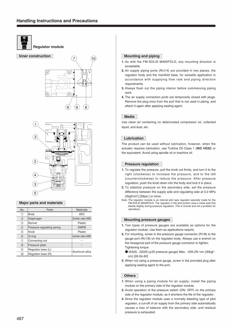
No. Parts Materials
w Diaphragm Synthetic rubber (NBR)
q
e
Body
Bonnet
ADC
Plastic
r Pressure regulating spring SWPB
t Knob Plastic
Aluminum alloy
y
i
O-ring
Pressure plate
Synthetic rubber (NBR)
Regulator module
Inner construction
Major parts and materials
Mounting and piping
1. As with the FM-SOLID MANIFOLD, any mounting direction is
acceptable.
2. Air supply piping ports (Rc1/4) are provided in two places, the
regulator body and the manifold base, for versatile application in
accordance with supplying flow rate and piping direction
requirements.
3. Always flush out the piping interior before commencing piping
work.
4. The air supply connection ports are temporarily closed with plugs.
Remove the plug once from the port that is not used in piping, and
attach it again after applying sealing agent.
Lubrication
The product can be used without lubrication, however, when the
actuator requires lubrication, use Turbine Oil Class 1 (ISO VG32) or
the equivalent. Avoid using spindle oil or machine oil.
Pressure regulation
1. To regulate the pressure, pull the knob out firmly, and turn it to the
right (clockwise) to increase the pressure, and to the left
(counterclockwise) to reduce the pressure. After pressure
regulation, push the knob down into the body and lock it in place.
2. To stabilize pressure on the secondary side, set the pressure
difference between the supply side and regulating side at 0.2 MPa
2kgf/cm2 [29psi.] or more.Note: The regulator module is an internal pilot type regulator specially made for the
FM-SOLID MANIFOLD. The regulator in the pilot portion uses a metal seat thatbleeds slightly during pressure regulation. This is normal and not a problem foroperations.
Mounting pressure gauges
1. Two types of pressure gauges are available as options for the
regulator module. Use them as applications require.
2. For mounting, screw in the pressure gauge connector (R1/8) to the
gauge port (Rc1/8) on the regulator body. Always use a wrench on
the hexagonal part of the pressure gauge connector to tighten.
Tightening torque
-GA20, -GD20 (φ20 pressure gauge) Max. –294.2N・cm 30kgf・cm [26.0in·lbf]
3. When not using a pressure gauge, screw in the provided plug after
applying sealing agent to the port.
Others
1. When using a piping module for air supply, install the piping
module on the primary side of the regulator module.
2. Avoid operation of the pressure switch (ON, OFF) on the primary
side of the regulator module, as it shortens the life of the regulator.
3. Since the regulator module uses a normally bleeding type of pilot
regulator, a cut-off of air supply from the primary side automatically
causes a loss of balance with the secondary side, and residual
pressure is exhausted.
MediaUse clean air containing no deteriorated compressor oil, collected
liquid, and dust, etc.
u
o
!0
Connecting rod
Regulator base (L)
Regulator base (R)
107
6
1
2
2
4
3
5
9 8
487
Handling Instructions and Precautions
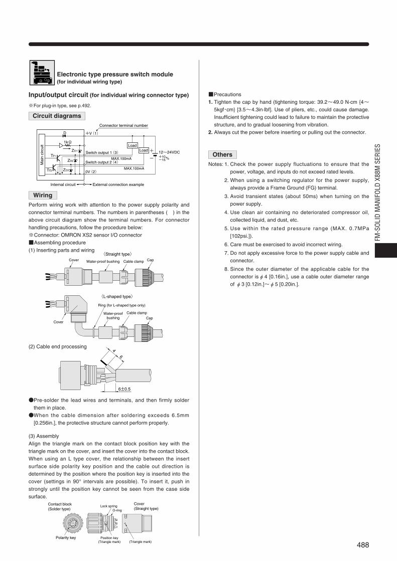
Electronic type pressure switch module(for individual wiring type)
Circuit diagrams
Wiring
Perform wiring work with attention to the power supply polarity and
connector terminal numbers. The numbers in parentheses ( ) in the
above circuit diagram show the terminal numbers. For connector
handling precautions, follow the procedure below:
※Connector: OMRON XS2 sensor I/O connector
Assembling procedure
(1) Inserting parts and wiring
(2) Cable end processing
Pre-solder the lead wires and terminals, and then firmly solder
them in place.
When the cable dimension after soldering exceeds 6.5mm
[0.256in.], the protective structure cannot perform properly.
(3) Assembly
Align the triangle mark on the contact block position key with the
triangle mark on the cover, and insert the cover into the contact block.
When using an L type cover, the relationship between the insert
surface side polarity key position and the cable out direction is
determined by the position where the position key is inserted into the
cover (settings in 90° intervals are possible). To insert it, push in
strongly until the position key cannot be seen from the case side
surface.
Input/output circuit (for individual wiring connector type) Precautions
1. Tighten the cap by hand (tightening torque: 39.2~49.0 N·cm 4~5kgf・cm [3.5~4.3in·lbf]. Use of pliers, etc., could cause damage.
Insufficient tightening could lead to failure to maintain the protective
structure, and to gradual loosening from vibration.
2. Always cut the power before inserting or pulling out the connector.
※For plug-in type, see p.492.
Cover Water-proof bushing CapCable clamp
Cover
Water-proofbushing Cap
Cable clamp
Ring (for L-shaped type only)
〈Straight type〉
〈L-shaped type〉
46
6±0.5
2 34
Position key(Triangle mark)
O-ringLock spring
(Triangle mark)
Contact block(Solder type)
Cover(Straight type)
Polarity key
Tr2
Tr1
1kΩ
0V(2)
+V(1)
ZD2
ZD3
ZD1
D
12~24VDC+10-15 %
+
-
MAX.100mA
MAX.100mA
External connection exampleInternal circuit
Switch output 2(4)
Switch output 1(3)
Connector terminal number
LoadLoad
Mai
n ci
rcui
t
Others
Notes: 1. Check the power supply fluctuations to ensure that the
power, voltage, and inputs do not exceed rated levels.
2. When using a switching regulator for the power supply,
always provide a Frame Ground (FG) terminal.
3. Avoid transient states (about 50ms) when turning on the
power supply.
4. Use clean air containing no deteriorated compressor oil,
collected liquid, and dust, etc.
5. Use within the rated pressure range (MAX. 0.7MPa
[102psi.]).
6. Care must be exercised to avoid incorrect wiring.
7. Do not apply excessive force to the power supply cable and
connector.
8. Since the outer diameter of the applicable cable for the
connector isφ4 [0.16in.], use a cable outer diameter range
of φ3 [0.12in.]~φ5 [0.20in.].
488
FM-S
OLID
MAN
IFOL
D X8
8M S
ERIE
S

Mode change key( )MODEy
0
GS520 1MPa
MODE
OUT2OUT1
q
w
r
t
e
y
Major parts and materials
3 1/2 digits LEDdisplay (Red)
Displays the detected pressure value, as well as thesetting contents, errors and key protect contents.
Switch output 1 lights up when ON.
Switch output 2 lights up when ON.
Switch output 1Operation display lamp (Orange)
Switch output 2Operation display lamp (Green)
Setting value UP key( )
Setting value DOWN key( )
・In the initial setting mode, each pressingof the key successively displays thepossible setting conditions.・Regarding setting values 1 and 2 in the
setting mode, pressing the key changesthe setting value to the low pressure side.・In the detection mode, continuously
pressing the key for 4 or more secondsgives the bottom hold display.
・In the initial setting mode, each pressingof the key successively displays thepossible setting digits.・Regarding setting values 1 and 2 in the
setting mode, pressing the key changesthe setting value to the high pressure side.・In the detection mode, continuously
pressing the key for 4 or more secondsgives the peak hold display.
・Each pressing of the key switches among the detection mode, setvalue 1 (P1) setting mode, and set value 2 (P2) setting mode.・In the detection mode, continuously pressing the key for about
3 seconds sets or cancel the key protect function.・In the detection mode, pressing the mode switch key while
pressing the setting value UP key ( ) switches to the Initialsetting mode.
In detectionmode, pressingboth keys at thesame timeperforms zero-point adjustment.
q
w
e
r
t
Parts Function
Load has short-circuited, andexcessive current isexperienced.
Pressure is applied during zero-point adjustment.
Cut the power, and then checkthe load.
Return the pressure port applied pressureto atmospheric pressure, and then performzero-point adjustment again.
Applied pressure exceedsthe upper limit of thedisplayed pressure range.
Applied pressure exceedsthe lower limit (reversepressure) of the displayedpressure range.
Restore the applied pressure tothe rated pressure range.
Error indication Details Processing
When an error occurs, take the following measures.
Error indication
Enables peak hold and bottom hold displays.
Four output modes offer flexible control.
Displays both the peak value (maximum value) and bottomvalue (minimum value) of the pressure fluctuation. Convenientwhen necessary to examine pressure variations or required toknow pressure setting values as a guide.
ON
OFFON
OFF
0 Setting value(P2)
Output switch 1
Output switch 2
Higher pressure (positive pressure type)
Response differential
Setting value(P1)
Setting value(P2)Setting value(P1)
Output switch 1
Output switch 2
Higher pressure (positive pressure type)
Response differential
Response differential
ON
OFFON
OFF
0
Output switch 1
Output switch 2
Setting value(P1) Setting value(P2)
Higher pressure (positive pressure type)
Response differential
Response differential
ON
OFFON
OFF
0
Setting value(P2)Setting value(P1)
Output switch 1
Output switch 2
Higher pressure (positive pressure type)
Response differential
Setting value(P3)
ON
OFFON
OFF
0
Hysteresis modeEnables freely setting the switch output response differential by setting values (hysteresis).
Window comparator modeEnables switching of output ON and OFF within the setting pressure range .
2-output modeVersatile applications such as detection of different types of work,control and warning.
Automatic sensitivity setting modeAll you need to do is to store the pressure values of Good items and NGitems at the site, then the switch sets the value automatically.
Continuing to press the keywill cause it to determine the bottom position.
Maximum
Minimum
Pre
ssur
e
Time
Continuing to press the key will cause it to determine the peak position.
0
GS520 1MPa
MODE
OUT2OUT1
0
GS520 1MPa
MODE
OUT2OUT1
1
2
3
4
Handling instructions and precautions
489
Handling Instructions and Precautions
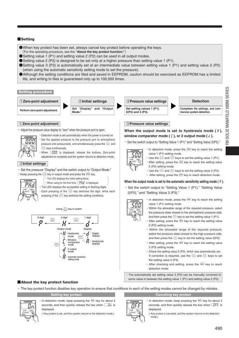
When key protect has been set, always cancel key protect before operating the keys.〔For the operating procedure, see the “About the key protect function.”〕Setting value 1 (P1) and setting value 2 (P2) can be used in all output modes.Setting value 2 (P2) is designed to be set only at a higher pressure than setting value 1 (P1).Setting value 3 (P3) is automatically set at an intermediate value between setting value 1 (P1) and setting value 2 (P2)
(when using the automatic sensitivity setting mode to set the pressure).Although the setting conditions are filed and saved in EEPROM, caution should be exercised as EEPROM has a limited
life, and writing to files is guaranteed only up to 100,000 times.
Setting
Setting procedure
About the key protect function
qZero-point adjustment
Perform zero-point adjustment.
wInitial settings
Set “Display” and “OutputMode.”
ePressure value settings
Set setting values 1 (P1),2(P2) and 3 (P3).
Detection
Completes the settings, and com-mences system detection.
qZero-point adjustment
・Adjust the pressure value display to “zero” when the pressure port is open.
0
GS520 1MPa
MODE
OUT2OUT1
・Detection mode is set automatically when the power is turned on.
・Set the applied pressure to the pressure port to atmospheric
pressure (not pressurized), and simultaneously press the and
keys continuously.
・When is displayed, release the buttons. Zero-point
adjustment is complete and the system returns to detection mode.
ePressure value settings
When the output mode is set to hysteresis mode ( ),window comparator mode ( ), or 2 output mode ( ).
・Set the switch output to “Setting Value 1 (P1)” and “Setting Value 2(P2).”
・The key protect function disables key operation to ensure that conditions in each of the setting modes cannot be changed by mistake.
0
GS510 1MPa
MODE
OUT2OUT1
・In detection mode, press the key to reach the setting
value 1 (P1) setting mode.
・Use the and keys to set the setting value 1 (P1).
・After setting, press the key to reach the setting value
2 (P2) setting mode.
・Use the and keys to set the setting value 2 (P2).
・ After setting, press the key to reach detection mode.MODE
MODE
MODE
・In detection mode, press the key to reach the setting
value 1 (P1) setting mode.
・Within the allowable range of the required pressure, select
the pressure state closest to the atmospheric pressure side,
and then press the key to set the setting value 1 (P1).
・After setting, press the key to reach the setting value
2 (P2) setting mode.
・Within the allowable range of the required pressure,
select the pressure state closest to the high pressure side,
and then press the key to set the setting value 2(P2).
MODE
MODE
When the output mode is set to the automatic sensitivity setting mode ( ).
・Set the switch output to “Setting Value 1 (P1),” “Setting Value
2(P2),” and “Setting Value 3 (P3).”
・The automatically set setting value 3 (P3) can be manually corrected to
some value in between the setting value 1 (P1) and setting value 2 (P2).
0
GS520 1MPa
MODE
OUT2OUT1
wInitial settings
・Set the pressure “Display” and the switch output to “Output Mode.”・Keep pressing the key in output mode and press the key.MODE
0
GS520 1MPa
MODE
OUT2OUT1
0
GS520 1MPa
MODE
OUT2OUT1
・The LED displays the initial setting items.
・When using for the first time, is displayed.
・The LED displays the acceptable setting in flashing digits.
・Each pressing of the key switches the digit, while each
pressing of the key switches the setting conditions.
・In detection mode, keep pressing the key for about 3
seconds, and then quickly release the key when is
displayed.
(・Key protect is set, and the system returns to the detection mode.)
MODE
0
GS520 1MPa
MODE
OUT2OUT1
・In detection mode, keep pressing the key for about 3
seconds, and then quickly release the key when is
displayed.
(・Key protect is canceled, and the system returns to the detection mode.)
MODE
3-digit 2-digit
key to switch
1-digit
Position Output mode Display
Posit
ive
press
ure
:kPa or MPa
:kgf/cm2
:bar
:psi
: Hysteresis mode
: Window comparator mode
: Digital display
: Analog bar display
: 2 output mode
: Automatic sensitivity setting mode
:mmHg
:inHg負圧
Using
Setting key protect Canceling key protect
・After setting, press the key to reach the setting value
3 (P3) setting mode.
・Check the setting value 3 (P3), which was automatically set.
・If correction is required, use the and keys to set
the setting value 3 (P3).
・After checking and setting, press the key to reach
detection mode.
MODE
MODE
490
FM-S
OLID
MAN
IFOL
D X8
8M S
ERIE
S
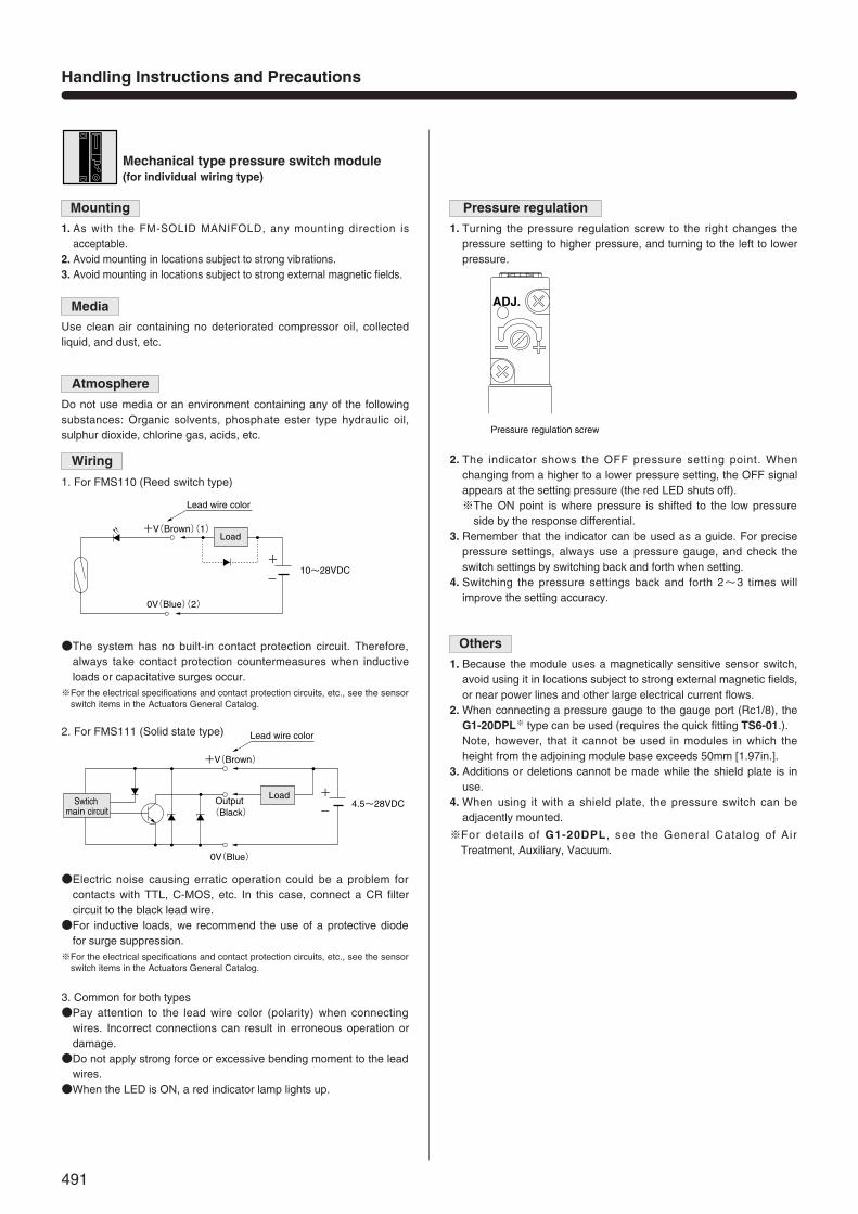
Mechanical type pressure switch module(for individual wiring type)
MediaUse clean air containing no deteriorated compressor oil, collectedliquid, and dust, etc.
Atmosphere
Do not use media or an environment containing any of the followingsubstances: Organic solvents, phosphate ester type hydraulic oil,sulphur dioxide, chlorine gas, acids, etc.
The system has no built-in contact protection circuit. Therefore,always take contact protection countermeasures when inductiveloads or capacitative surges occur.
※For the electrical specifications and contact protection circuits, etc., see the sensorswitch items in the Actuators General Catalog.
Wiring
1. For FMS110 (Reed switch type)
2. For FMS111 (Solid state type)
Electric noise causing erratic operation could be a problem forcontacts with TTL, C-MOS, etc. In this case, connect a CR filtercircuit to the black lead wire.For inductive loads, we recommend the use of a protective diode
for surge suppression.※For the electrical specifications and contact protection circuits, etc., see the sensor
switch items in the Actuators General Catalog.
3. Common for both typesPay attention to the lead wire color (polarity) when connecting
wires. Incorrect connections can result in erroneous operation ordamage.Do not apply strong force or excessive bending moment to the lead
wires.When the LED is ON, a red indicator lamp lights up.
Mounting
1. As with the FM-SOLID MANIFOLD, any mounting direction isacceptable.
2. Avoid mounting in locations subject to strong vibrations.3. Avoid mounting in locations subject to strong external magnetic fields.
Pressure regulation
1. Turning the pressure regulation screw to the right changes thepressure setting to higher pressure, and turning to the left to lowerpressure.
Others
1. Because the module uses a magnetically sensitive sensor switch,avoid using it in locations subject to strong external magnetic fields,or near power lines and other large electrical current flows.
2. When connecting a pressure gauge to the gauge port (Rc1/8), theG1-20DPL※ type can be used (requires the quick fitting TS6-01.).
2. Note, however, that it cannot be used in modules in which theheight from the adjoining module base exceeds 50mm [1.97in.].
3. Additions or deletions cannot be made while the shield plate is inuse.
4. When using it with a shield plate, the pressure switch can beadjacently mounted.
※For details of G1-20DPL, see the General Catalog of AirTreatment, Auxiliary, Vacuum.
2. The indicator shows the OFF pressure setting point. Whenchanging from a higher to a lower pressure setting, the OFF signalappears at the setting pressure (the red LED shuts off).※The ON point is where pressure is shifted to the low pressure
side by the response differential.3. Remember that the indicator can be used as a guide. For precise
pressure settings, always use a pressure gauge, and check theswitch settings by switching back and forth when setting.
4. Switching the pressure settings back and forth 2~3 times willimprove the setting accuracy.
Pressure regulation screw
ADJ.
Lead wire color
+V(Brown)(1)
0V(Blue)(2)
-
+10~28VDC
Load
0V(Blue)
Output(Black)
Lead wire color
+V(Brown)
+
-4.5~28VDCSwtich
main circuit
Load
491
Handling Instructions and Precautions

Electronic and mechanical type pressure switchmodule (for collective wiring type)
Circuit diagrams
Major functions and part names of the terminal block
1. Electronic type pressure switch (for collective wiring type)
2. Mechanical type pressure switch
Reed switch type (2-lead wires)
Solid state type (3-lead wires)
Pay attention to the power supply polarity and the terminal block’s terminal numbersfor wiring connections.
Only output 1 is available for FMS220 (collective wiring type〈plug-in type〉).
Pay attention to the power supply polarity and the terminal block’s terminal numbersfor wiring connections.
Pay attention to the power supply polarity and terminal block sequence for wiringconnections.
1. 10-pin terminal block with M3 threadNote: The terminals should be 6mm [0.24in.] or less for both the round-type terminals
and Y-type terminals.
Note: Combination mounting of up to 3 plug-in type pressure switch modules can bewired to a single terminal block module.
2. Terminal location (Terminal block label)2. Terminal location of pressure switch module up to 3 units.
The wiring from the pressure switches is all connected to a suppliedterminal block module.
Terminal
Terminal block label
(Output) (Output) (Output)+ 出力- + 出力- + 出力-
MAX.6
MAX.6
Terminal block Applicable terminal
M3 MAX4
6.02
Lead wire color
+V(Brown)
0V(Blue)
-
+10~28VDC
Load
MAX.100mA
External connectionInternal circuit
Switch output 1
Mai
n ci
rcui
t
Tr2
Tr1
1kΩ
0V
+V
ZD2
ZD3
ZD1
D
12~24VDC+10-15 %
+
-
Load
+V(Brown)
0V(Blue)
Output(Black)
Lead wire color
+
-4.5~28VDC
LoadSwitchmain circuit
492
FM-S
OLID
MAN
IFOL
D X8
8M S
ERIE
S
First terminal location Second terminal location Third terminal location
(Output) (Output) (Output)
+ ― 出力 + ― 出力 + ― 出力

500 [19.7]500 [19.7]500 [19.7]500 [19.7]500 [19.7]Cylinder speedNote 2
mm/s [in./sec.]
124(6)(10)Usable numberNote 1
φ63 [2.480]φ50 [1.969]φ40 [1.575]φ32 [1.260]φ25 [0.984]Bore size mm [in.]
Solenoid valve model Number of valvesNote
110 series 10
180 series 14
Air preparation moduleOther information and data
Maximum flow rate of FMR200 regulator module
When using a regulator module to supply air to valve modules, thenumber of valves used could lead to insufficient air supply pressureand flow rates, resulting in erratic valve operation or insufficientactuator output. See the table below when determining the number ofregulator modules:
Ejector module
General precautions
The FMJ05/07E2 ejector module differs from the conventional type ofME05/07-E2 series ejector, in that it does not have a built-in checkvalve. As a result, switching off the air supply solenoid valve sets theV port side to the atmospheric pressure level, as in the E1 type.When countermeasures must be taken to keep vacuum within avolume chamber, or to prevent workpieces from falling during powerfailure, etc., always take sufficient precautions before use.The vacuum breaking valves (with twin valves) are particularlyeffective for workpieces that need to be picked off more positively andquickly.Replacement filters are also available (order code: ME05MA-F,ME07MA-F). Replace the filter on a periodic basis.For specifications with a built-in check valve, consult us.
FMJE2 SymbolCylinder size and speed at the maximum flow rate (reference data)
Conditions
Primary pressure : 0.7MPa [102psi.] (constant)
Secondary pressure : 0.5MPa [73psi.] (regulated at regulator module)
Valve used : 180 series (direct piping type)
Filter used : FMF200 filter module
Piping module used : FMP-FJ10S
Tube used between a valve and cylinder : N8-B-1000mm [39in.]
Note: The valve number means the number of valves that can simultaneously supplyair to the secondary side with a single regulator module.
Notes: 1. The usable number refers to the number of cylinders that can besimultaneously operated by a single regulator module.
2. Cylinder speed is the actual value measured in the above conditions.
Since the number of valves shown above is equivalent to the numberof piping modules used, the number of piping modules also equalsthe number of regulator modules.
Vacuumbreaking valve Supply valve
P
V
493
Handling Instructions and Precautions
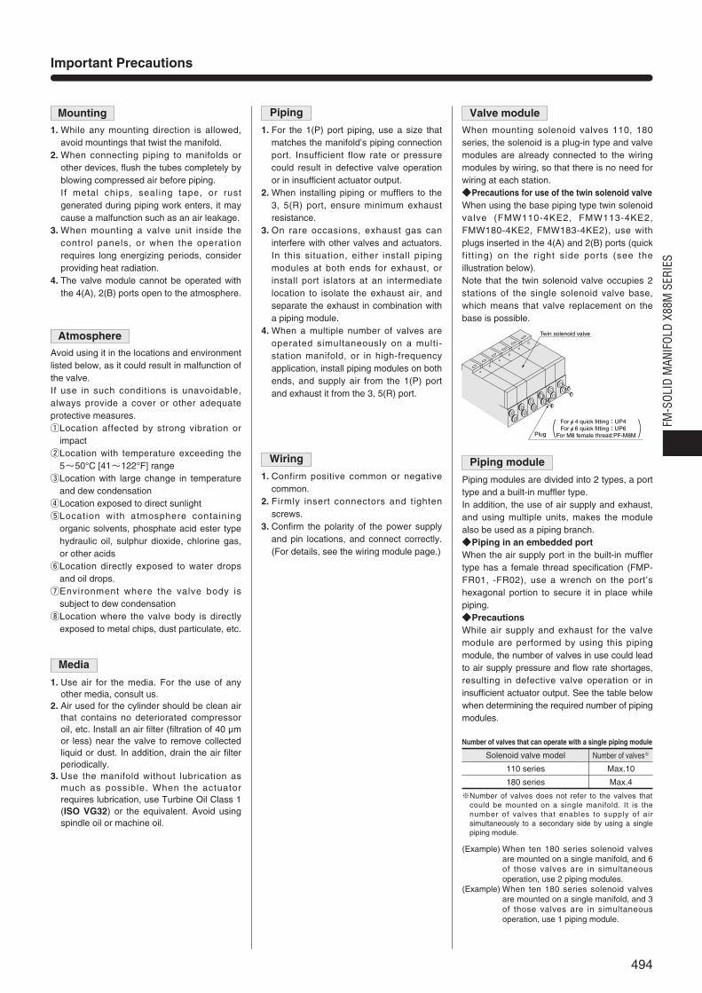
Solenoid valve model
110 series
Number of valves※
Max.10
180 series Max.4
Important Precautions
Piping
1. For the 1(P) port piping, use a size thatmatches the manifold’s piping connectionport. Insufficient flow rate or pressurecould result in defective valve operationor in insufficient actuator output.
2. When installing piping or mufflers to the3, 5(R) port, ensure minimum exhaustresistance.
3. On rare occasions, exhaust gas caninterfere with other valves and actuators.In this situation, either install pipingmodules at both ends for exhaust, orinstall port islators at an intermediatelocation to isolate the exhaust air, andseparate the exhaust in combination witha piping module.
4. When a multiple number of valves areoperated simultaneously on a multi-station manifold, or in high-frequencyapplication, install piping modules on bothends, and supply air from the 1(P) portand exhaust it from the 3, 5(R) port.
Wiring
1. Confirm positive common or negativecommon.
2. Firmly insert connectors and tightenscrews.
3. Confirm the polarity of the power supplyand pin locations, and connect correctly.(For details, see the wiring module page.)
Mounting
1. While any mounting direction is allowed,avoid mountings that twist the manifold.
2. When connecting piping to manifolds orother devices, flush the tubes completely byblowing compressed air before piping.
2. If metal chips, sealing tape, or rustgenerated during piping work enters, it maycause a malfunction such as an air leakage.
3. When mounting a valve unit inside thecontrol panels, or when the operationrequires long energizing periods, considerproviding heat radiation.
4. The valve module cannot be operated withthe 4(A), 2(B) ports open to the atmosphere.
Atmosphere
Avoid using it in the locations and environmentlisted below, as it could result in malfunction ofthe valve.If use in such conditions is unavoidable,always provide a cover or other adequateprotective measures.qLocation affected by strong vibration or
impactwLocation with temperature exceeding the
5~50°C [41~122°F] rangeeLocation with large change in temperature
and dew condensationrLocation exposed to direct sunlighttLocation with atmosphere containing
organic solvents, phosphate acid ester typehydraulic oil, sulphur dioxide, chlorine gas,or other acids
yLocation directly exposed to water dropsand oil drops.
uEnvironment where the valve body issubject to dew condensation
iLocation where the valve body is directlyexposed to metal chips, dust particulate, etc.
Media
Number of valves that can operate with a single piping module
Valve module
When mounting solenoid valves 110, 180series, the solenoid is a plug-in type and valvemodules are already connected to the wiringmodules by wiring, so that there is no need forwiring at each station.Precautions for use of the twin solenoid valveWhen using the base piping type twin solenoidvalve (FMW110-4KE2, FMW113-4KE2,FMW180-4KE2, FMW183-4KE2), use withplugs inserted in the 4(A) and 2(B) ports (quickfitt ing) on the right side ports (see theillustration below).Note that the twin solenoid valve occupies 2stations of the single solenoid valve base,which means that valve replacement on thebase is possible.
Piping module
Piping modules are divided into 2 types, a porttype and a built-in muffler type.In addition, the use of air supply and exhaust,and using multiple units, makes the modulealso be used as a piping branch.Piping in an embedded portWhen the air supply port in the built-in mufflertype has a female thread specification (FMP-FR01, -FR02), use a wrench on the port’shexagonal portion to secure it in place whilepiping.PrecautionsWhile air supply and exhaust for the valvemodule are performed by using this pipingmodule, the number of valves in use could leadto air supply pressure and flow rate shortages,resulting in defective valve operation or ininsufficient actuator output. See the table belowwhen determining the required number of pipingmodules.
(Example) When ten 180 series solenoid valvesare mounted on a single manifold, and 6of those valves are in simultaneousoperation, use 2 piping modules.
(Example) When ten 180 series solenoid valvesare mounted on a single manifold, and 3of those valves are in simultaneousoperation, use 1 piping module.
※Number of valves does not refer to the valves thatcould be mounted on a single manifold. It is thenumber of valves that enables to supply of airsimultaneously to a secondary side by using a singlepiping module.
Twin solenoid valve
Plug( )Forφ4 quick fitting:UP4 Forφ6 quick fitting:UP6
For M8 female thread:PF-M8M
494
FM-S
OLID
MAN
IFOL
D X8
8M S
ERIE
S1. Use air for the media. For the use of any
other media, consult us.2. Air used for the cylinder should be clean air
that contains no deteriorated compressoroil, etc. Install an air filter (filtration of 40 µmor less) near the valve to remove collectedliquid or dust. In addition, drain the air filterperiodically.
3. Use the manifold without lubrication asmuch as possible. When the actuatorrequires lubrication, use Turbine Oil Class 1(ISO VG32) or the equivalent. Avoid usingspindle oil or machine oil.

Purposes Model
Block supply air FMB-P
Block exhaust air FMB-R
Block supply and exhaust air FMB-A
The following 3 types of port isolators areavailable:
Precautions(1) Confirm a marking label on the bottom of
the manifold for port isolator locations.(Because the port isolators are assembledinside the manifold base, the outwardappearance and dimensions do notchange.)
(2) While a port isolator can be installed in anylocation required on each module, itsposition cannot be changed after shipping.
(3) The port isolator is located on the left side ofthe designated module (solenoid on top).Therefore, it blocks the air for that portion(see the diagram).
Power supply terminal blocks (power supplyconnection terminals) are provided for theFMC-F200, -D250, -E250 units. In output unitswhere power supply from the output isrequired for the internal circuits (see thediagram), power lines can be connected to thesame cable, in the same way as load(solenoid) lines.
Connection diagram between PC andmanifold (connector)
Example of system configuration
When the controller is negative common, themanifold side should be positive common.And when the controller is positive common,the manifold side should be negativecommon.In this system configuration example, thecontroller side is always negative commontype (and the manifold side is positivecommon type).When the output unit requires no
power supply.<A system that uses a cable to transmit
control voltage only>The power supply connection terminal
(Fcc, D-sub connector type) uses positivepolarity wiring only, with the negativepolarity left open as a dead terminal.Since the terminal block type’s common
is a positive polarity, use it as shown forwiring:
When the output unit requires a powersupply
Method q
Connect positive and negative powersupply to the power supply connectionterminal, and supply power to the outputunit through the connection cable ’spositive and negative lines.Can be shared with the same cable as
the control voltage.
Method w
Supply power to the output unit, andconnect a positive line to the manifoldside.Leave the negative polarity as a dead
terminal.For the terminal block type, connect the
positive line to the common.
Note: The terminal block type uses theprocedure shown below.
FMC-E250
20,21,22
23,24,25
FMC-D250
20,21,22
23,24,25
FMC-F201
19, 19
10, 20
FMC-F200
17, 18
19, 20
Line A : COM (0V or negative) lineLine B : +V line
(-)
(+)
Vale modulePiping module
Module with a port isolator
Port isolator FMB-P
0.3MPa(Supply)
0.5MPa(Supply)
0.3MPa 0.5MPa 0.5MPa
CableAC100VAC200V
FM-SOLIDMANIFOLD+
ー
Pow
er u
nit
Con
trol
ler
body
Out
put u
nit
Stabilized power
supply (DC)
DC24Vor
DC12V
L
B
A
L
LLLLLL
L
L
B
A
OUT (n)
+V
+V
OUT
COM
01234
nCOM
PC in
terna
l circ
uit
S1
S2
S3
Sn
Connection cable
Manifold
Solenoid
Power supplyconnection terminal
DC24VorDC12V
PC
inte
rnal
circ
uit
(ー)
(+)
Line A
Line B
PC
123
123
n n
+V
COM
CableAC100VAC200V
FM-SOLIDMANIFOLD
+
ー
Pow
er u
nit
Con
trol
ler
body
Out
put u
nit
Stabilizedpower
supply (DC)
CableAC100VAC200V
FM-SOLIDMANIFOLD+
ー
Pow
er u
nit
Con
trol
ler
body
Out
put u
nit
Stabilized power
supply (DC)
495
Important Precautions
Port isolator How to use the power supply connection terminal
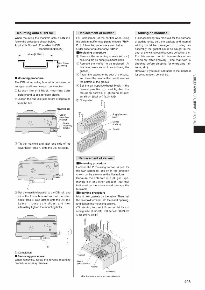
Replacement of muffler
For replacement of the muffler when usingthe built-in muffler type piping module (FMP-F), follow the procedure shown below.Order code for muffler only: F3P-01Replacing procedureq Remove the mounting screws (4 pcs.)
securing the air supply/exhaust block.w Remove the muffler to be replaced. (At
this time, take caution to avoid losing thegasket.)
e Attach the gasket to the seat of the base,and insert the new muffler until it reachesthe bottom of the groove.
r Set the air supply/exhaust block in thenormal posit ion ①, and tighten themounting screws. (Tightening torque:58.8N·cm 6kgf·cm [5.2in·lbf])
t Completion
Replacement of valves
Removing procedureRemove the 2 mounting screws (4 pcs. forthe twin solenoid), and lift in the directionshown by the arrow (see the illustration).Because the solenoid is a plug-in type,moving it in any other direction than thatindicated by the arrow could damage theterminals.Mounting procedureMount new gaskets on the valve. Then, setthe solenoid terminal into the insert opening,and tighten the mounting screws.(Tightening torque:110 series:44.1N·cm4.5kgf·cm [3.9in·lbf], 180 series: 68.6N·cm7kgf·cm [6.4in·lbf]
Mounting onto a DIN rail
When mounting the manifold onto a DIN rail,follow the procedure shown below.Applicable DIN rail : Equivalent to DIN
standard (EN50022)
Mounting procedure
The DIN rail mounting bracket is composed of
an upper and lower two-part construction.
q Loosen the end block mounting bolts
beforehand (2 pcs. for each block).
※Loosen the nut until just before it separates
from the bolt.
w Tilt the manifold and latch one side of the
lower hook (area A) onto the DIN rail edge.
e Set the manifold parallel to the DIN rail, andslide the lower bracket so that the otherhook (area B) also latches onto the DIN rail.Leave it loose as it sl ides, and thenalternately tighten the mounting bolts.
r CompletionRemoving procedureWhen removing, follow the reverse mountingprocedure for easy removal.
Adding on modules
If disassembling this manifold for the purposeof adding units, etc., the gaskets and internalwiring could be damaged, or during re-assembly the gasket could be caught in thegap, or the wiring could become defective, etc.For this reason, avoid disassembly or re-assembly after delivery. (The manifold ischecked before shipping for energizing, airleaks, etc.)However, if you must add units to the manifoldfor some reason, consult us.
35mm [1.378in.]
Min. 7.5mm[0.295in.]
A
Supply/exhaust block
Muffler(F3P-01)
Gasket
P
Terminal
Gasket(Exhaust valve)
Gasket
Valve base
(The illustration is for the twin solenoid valve.)
Nut
Lower mounting bracket
Upper mounting bracket
Mounting bolt
B
496
FM-S
OLID
MAN
IFOL
D X8
8M S
ERIE
S

497


![[N] Mukodai and Koganei Park Course · 2018-02-16 · Koganei Park(Best 50 trees in Nishitokyo City: Oshimazakura cherry tree) Icons: Shrines and Temples Park Other Tokyo Metropolitan](https://img.pdfslide.net/doc/110x75/5f9542a25afc035e083acdaa/n-mukodai-and-koganei-park-course-2018-02-16-koganei-parkbest-50-trees-in-nishitokyo.jpg)