Embed Size (px)
Citation preview

Module Configuration 383Examples of FM-SOLID MANIFOLD X80M Configuration 385Module Mass and Dimensions 387Manifold Order Codes 388Module Order Codes 391Wiring Modules 393
Details of Wiring Specifications 394Detailed Diagram of Solenoid Wiring System 396Dimensions 397
Compact Serial Transmission System 399Piping Modules 403
Dimensions 404Valve Modules 405
Cylinder Operating Speed, Flow Rate 406Dimensions 407
Block-off Plate Module 412Dimensions 413
End Blocks 414Dimensions 415
Handling Instructions and Precautions 417Important Precautions 418
CAD drawing data catalogis available.
382
VALVES GENERAL CATALOG
INDEX
FM-SOLID MANIFOLDSERIES
Before use, be sure to read the “Safety Precautions” on p. 31.Caution
FM-S
OLID
MAN
IFOL
D X8
0M S
ERIE
S

マフラ内蔵
Module Configuration
Wiring modules, p.393
Flat cable connector type
● Accommodates up to 8 solenoids (10 pins)
● Accommodates up to 16 solenoids (20 pins)
D-sub connector type Terminal block type
Piping modules, p.403
Built-in quick fitting type
Built-in straight quick fitting Built-in elbow quick fitting
P port female thread type
All port female thread type
マフラ内蔵
Cable assemblyp.1039
Connector p.1040
Cable p.1040
Remote controlbox, p.1041
●For details of specifications for modules and acces-sories, etc., see the pages following each title.
●For the FM-SOLID MANIFOLD X80M series ordercodes, see p.388.
With built-in muffler
For Fuji Electric FAComponents & SystemsT Link Mini
For NKE, KURODA PRECISION INDUSTRIESUNI-WIRE® System
For SUNXS-LINK
For KEYENCEKZ-R
For KOYO ELECTRONICS INDUSTRIESSA Bus
For OMRONCompoBus/D
For OMRONSYSBUS Wire System
For OMRONCompoBus/S
For OMRONB7A Link Terminal
For Mitsubishi ElectricMELSECNET/MINI-S3
For Mitsubishi ElectricMELSEC I/O LINK
For Mitsubishi ElectricCC-Link
※UNI-WIRE® System is a serial parallel transmissionsystem developed jointly by NKE and KURODAPRECISION INDUSTRIES.
Compact serial transmission system, p.399
383
SeriesFM-SOLID MANIFOLD
With built-in muffler
With built-in muffler

Valve modules (2-, 3-port, 5-port), p.405 ブロックプレートモジュール256ページ
Solenoid valves 090 series
Sin
gle
sole
noid
Sin
gle
sole
noid
Tw
inso
leno
idT
ande
mso
leno
id
Bas
epi
ping
type
●Voltage: DC12V, DC24V
Sticker, p.388
Port isolator, p.388
1(P), 3, 5(R) port all port block type1(P) port block type3, 5(R) port block type
DIN rail mounting bracket, p.388
End blocks, p.414
End block module type
With DIN rail mounting bracket type
End block upper piping type
End blockside piping type
Block-off plate module, p.412
384
FM-S
OLID
MAN
IFOL
D X8
0M S
ERIE
S

Examples of FM-SOLID MANIFOLD X80M Configuration
Manifold Configuration Example 1.
265.2
5722
34×15 (Pitch) 8×10.2 (Pitch) 2×10.2 2×153×20.4 (Pitch)
3 4-φ3.4
63 708
PR
3・5(R)�
1(P)�
P
A
B
FMC
R-F
200
FMC
R-F
100
FMC
R-D
250-
M2.
6FM
CR
-T07
0
FMW
R09
0E1-
J4S
FMW
R09
0-4E
1-J4
S
FMW
R09
0-4K
E2-J
4S
FMW
R09
0-B
P-J4
SFM
PR-F
R01
FMPR
-PR
01S
1 2 3 4 5 6 7 8 9 10 11 12 13 14 15 16 17 18 19 �
A
B
Module No.
(Pitch) (Pitch)
Note: This is not a manifold configuration for use in actual applications.
Module No. Model
No.1 FMCR-F200
No.2 FMCR-F100
No.3 FMCR-D250-M2.6
No.4 FMCR-T070
No.5 FMWR090E1-J4S
No.6~12 FMWR090-4E1-J4S
No.13~15 FMWR090-4KE2-J4S
No.16~17 FMWR090-BP-J4S
No.18 FMPR-FR01
No.19 FMPR-PR01S
385
Manifold Configuration Example 2.
46.522
PRR
P
226.9214.2
P P
7046.5
1163
72-R1.7
1(P) Port
1(P) Port
3, 5(R) Port
4(A) Port
2(B) Port
B
A
B
A
2 3 4 5 6 7 8 10 11 12 13 14 159↑�
Module No.1
Manifold Configuration Example 3. Combination Mounting of Single Solenoid Valves and Tandem Solenoid Valves
A BD
B
A B
A
A BD
B
A B
A
A BD
B
A B
A
A BD
B
A B
A
A BD
B
A B
A
A BD
B
A B
A
111.696.6
5538
4.6
63 708
57
82.6
7
2-R1.7
B
A
B
A
2 3 4 5 6 7 8 9
PRR
P
Module No.1
Order code: X80M-ED No.1 FMCR-D250-M2.6 DC24VNo.2 FMWR090E1-J6S DC24VNo.3~5 FMWR090-4E1-J6S DC24VNo.6~7 FMWR090-4KE2-J6S DC24VNo.8 FMPR-FJ8SNo.9 FMBR-PNo.10 FMWR090-4E1-J6S DC24VNo.11~13 FMWR090-4KE2-J6S DC24VNo.14 FMWR090-BP-J6SNo.15 FMPR-FJ8S
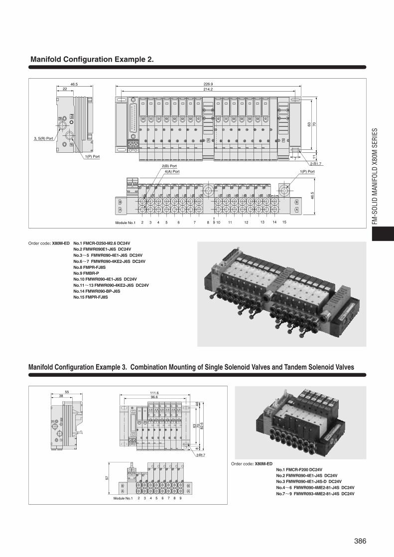
Order code: X80M-EDNo.1 FMCR-F200 DC24VNo.2 FMWR090-4E1-J4S DC24VNo.3 FMWR090-4E1-J4S-D DC24VNo.4~6 FMWR090-4ME2-81-J4S DC24VNo.7~9 FMWR093-4ME2-81-J4S DC24V
386
FM-S
OLID
MAN
IFOL
D X8
0M S
ERIE
S

Module Mass and Dimensions
Wiring module
FMCR-F10□ 30 [1.06] 15 [0.59] 57 [2.24]
FMCR-F20□ 38 [1.34] 15 [0.59] 57 [2.24]
FMCR-D250-□ 44 [1.55] 15 [0.59] 46 [1.81]
FMCR-G250-□ 51 [1.80] 15 [0.59] 46 [1.81]
FMCR-T070 37 [1.31] 15 [0.59] 50 [1.97]
YS101□/YS102□ 80/65 [2.82/2.29] 30.6 [1.205] 66.9 [2.634]
YS111□,YS121□,YS161□,YS171□ 105 [3.70] 30.6 [1.205] 66.9 [2.634]
YS181□,YS1A1□,YS1A2□ 105 [3.70] 30.6 [1.205] 66.9 [2.634]
YS131□,YS132□,YS1B1□ 100 [3.53] 30.6 [1.205] 66.9 [2.634]
YS141□/YS142□ 85/70 [3.00/2.47] 30.6 [1.205] 66.9 [2.634]
YS151□/YS152□ 70/67 [2.47/2.36] 30.6 [1.205] 66.9 [2.634]
FMPR-FJ8S 36 [1.27] 15 [0.59] 39 [1.54]
FMPR-FJ8L 42 [1.48] 15 [0.59] 55.4 [2.181]
FMPR-FR01 37 [1.31] 15 [0.59] 39 [1.54]
FMPR-PR01S 50 [1.76] 15 [0.59] 40.5 [1.594]
FMWR090E1 42 [1.48]※ 10.2 [0.402] 36 [1.42]※
FMWR090-4E1 42[1.48]※ 10.2 [0.402] 36 [1.42]※
FMWR090-4KE2 84 [2.96]※ 20.4 [0.803] 36 [1.42]※
FMWR090-4ME2 62 [2.19]※ 10.2 [0.402] 55.8 [2.197]
FMWR093-4ME2 67 [2.36]※ 10.2 [0.402] 55.8 [2.197]
FMWR090-BP 24 [0.85]※ 10.2 [0.402] 23.6 [0.929]
X80M 30 [1.06] 6 [0.24] 22.5 [0.886]
X80M-ER 47 [1.66] Left side 6 [0.24]/Right side 17 [0.67] 22.5 [0.886]
X80M-EL 47 [1.66] Left side 17 [0.67]/Right side 6 [0.24] 22.5 [0.886]
X80M-ED 64 [2.26] Left side 17 [0.67]/Right side 17 [0.67] 22.5 [0.886]
X80M-UR 80 [2.82] Left side 6 [0.24]/Right side 15 [0.59] 39 [1.54]
X80M-UL 80 [2.82] Left side 15 [0.59]/Right side 6 [0.24] 39 [1.54]
X80M-UD 130 [4.59] Left side 15 [0.59]/Right side 15 [0.59] 39 [1.54]
X80M-DN 118 [4.16] (88 [3.10])Note Left side 12.7 [0.500]/Right side 12.7 [0.500] 31 [1.22]
Compact serial transmission block
Piping module
Valve module
Block-off plate module
End block
Item
Module typeMass g [oz.] Width mm [in.] Height mm [in.]
Remark: The heights are those with the end blocks installed.Note: Figures in parentheses ( ) are the mass for the DIN rail mounting
bracket only.
※: For -J4S
X80M-DN 30+88=118No.1 FMCR-F100 DC24V 30×1 =30No.2~9 FMWR090-4E1-J4S DC24V 42×8 =336No.10 FMPR-FJ8S 36×1 =36118+30+336+36=520g [18.34oz.]
FM-SOLID MANIFOLD X80M Series Basic Specifications
387
Item Manifold basic model X80M
Media Air
Operating pressure range MPa {kgf/cm2} [psi.] 0.2 ~0.7 {2.0 ~7.1} [29~102]
Proof pressure MPa {kgf/cm2} [psi.] 1.05 {10.7} [152]
Operating temperature range°C [°F] 5~50 [41~122]
(atmosphere and media)
Wiring typeCollective wiring type from wiring module
(Flat cable connector type, D-sub connector type, terminal block type)
End block End block module type/End block piping type
Manifold mounting type Direct mounting type/DIN rail mounting type
Common terminal wiring Positive common/Negative common

Manifold Order Codes
Order Codes
-ED -DN -CM No.1 FMCR-F200…
No.2… …
FMWR090-4E1…
No.n
X80M
388
FM-S
OLID
MAN
IFOL
D X8
0M S
ERIE
S
Manifold basic modelEnd block type Mounting type Common terminal wiring
Module No. Module model
●Select from the valve modules,wiring modules, or piping modules.●One sticker is provided for each
manifold.
1. The number of the modules for the FM-SOLIDMANIFOLD X80M series should be 20 stations orless.
2. When a pressure drop is considered possible, suchas when a multiple number of valves are operatedsimultaneously on a multi-station manifold, orduring high cycle applications, add a piping moduleat an intermediate position of the manifold.
3. When combining 2 or more terminal block typewiring modules (FMCR-T070) side by side, thewiring space for each terminal block becomes tight.Depending on the wiring types and conditions, eachwiring group’s crimped terminals or lead wirescould interfere with other terminal blocks, and itcould be difficult to achieve an orderly wiring. Whenusing multiple wiring modules, therefore, carefullystudy the designated locations of each module orconsult us.
End blockmounting type
Blank qEnd blockmodule typeAlways specify thepiping module. (1(P) and 3, 5(R)ports are plumbedat the pipingmodule.)
-ER wEnd blockright side piping type1(P), 3, 5(R), and PR piping ispossible at the end block. Thepiping direction is lateral right(←direction).1(P), 3, 5(R) ports: 1/8PR port: M5 PR port is separated.
-ELeEnd block
left side piping typeSame specificationas the above w.The piping direction,however, is lateralleft (→ direction).
-EDrEnd block
both sides piping typeSame specificationas the above w.The piping direction,however, can be inboth lateral directions.
-UR tEnd block upper right side piping type1(P) and 3, 5(R) piping ispossible at the end block.The piping direction isupward right. 1(P) and 3,5(R) ports: 1/8 (3, 5(R) andPR share the same 3, 5(R)port)
-UL yEnd block upper left side piping typeSame specificationas the above t.The piping direction,however, is upwardleft.
-UDuEnd block
upper both sides piping typeSame specification asthe above t. The piping direction,however, can be in bothupward directions.
Blank
Positive common
With DIN rail mounting bracket type
-DN -CM
Negative common
■ Order codes for additional parts (To be ordered separately)
●DIN rail mounting bracket (1 set)
X801-DN
■About a port isolatorUse of a port isolator at an intermediate position on the manifold andinstalling a piping module to an individual group makes the use of 2 or 3different pressures possible, and prevents exhaust interference from the mainexhaust. When ordering, enter a port isolator as 1 module.
●Number stickers (1 set of 5 sheets)
X802-01
Port isolator typeType Function
FMBR-A 1(P), 3, 5(R) port all port block
FMBR-P 1(P) port block
FMBR-R 3, 5(R) port block
Blank
※Although port isolators can be installed into modules at any location, theycannot be disassembled to change the position after shipping.
End block shape
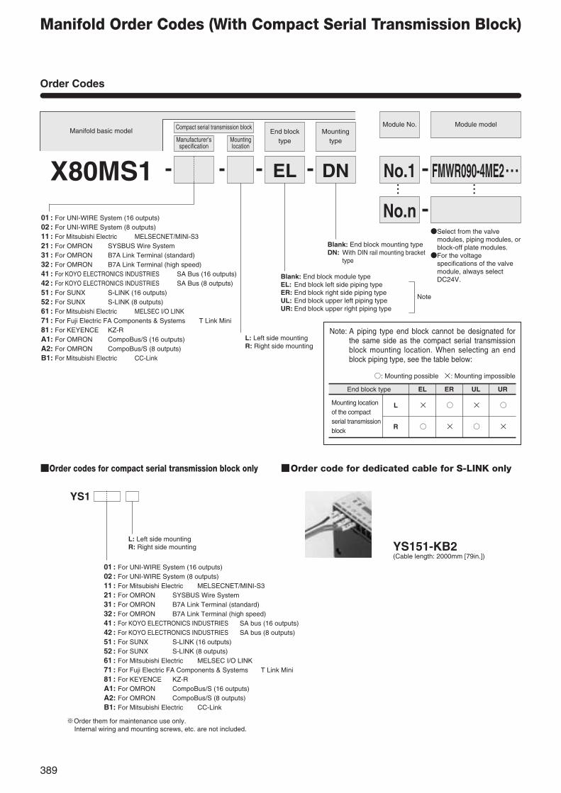
Manifold Order Codes (With Compact Serial Transmission Block)
Order Codes
389
Manifold basic model
X80MS1
Compact serial transmission blockEnd block
typeMounting
typeManufacturer’sspecification
Mountinglocation
DN No.1 FMWR090-4ME2・・・… …
No.n
Module No. Module model
EL
Blank: End block mounting typeDN: With DIN rail mounting bracket
type
●Select from the valvemodules, piping modules, orblock-off plate modules.●For the voltage
specifications of the valvemodule, always selectDC24V.Blank: End block module type
EL: End block left side piping type ER: End block right side piping type UL: End block upper left piping type UR: End block upper right piping type
L: Left side mountingR: Right side mounting
Note
Note: A piping type end block cannot be designated forthe same side as the compact serial transmissionblock mounting location. When selecting an endblock piping type, see the table below:
○: Mounting possible ×: Mounting impossible
End block type EL ER UL UR
L × ○ × ○
R ○ × ○ ×
Mounting locationof the compactserial transmissionblock
■Order codes for compact serial transmission block only ■Order code for dedicated cable for S-LINK only
YS1
L: Left side mountingR: Right side mounting
※Order them for maintenance use only.Internal wiring and mounting screws, etc. are not included.
YS151-KB2(Cable length: 2000mm [79in.])
01 : For UNI-WIRE System (16 outputs)02 : For UNI-WIRE System (8 outputs)11 : For Mitsubishi Electric MELSECNET/MINI-S321 : For OMRON SYSBUS Wire System31 : For OMRON B7A Link Terminal (standard)32 : For OMRON B7A Link Terminal (high speed)41 : For KOYO ELECTRONICS INDUSTRIES SA Bus (16 outputs)42 : For KOYO ELECTRONICS INDUSTRIES SA Bus (8 outputs)51 : For SUNX S-LINK (16 outputs)52 : For SUNX S-LINK (8 outputs)61 : For Mitsubishi Electric MELSEC I/O LINK71 : For Fuji Electric FA Components & Systems T Link Mini81 : For KEYENCE KZ-RA1: For OMRON CompoBus/S (16 outputs)A2: For OMRON CompoBus/S (8 outputs)B1: For Mitsubishi Electric CC-Link
01 : For UNI-WIRE System (16 outputs)02 : For UNI-WIRE System (8 outputs)11 : For Mitsubishi Electric MELSECNET/MINI-S321 : For OMRON SYSBUS Wire System31 : For OMRON B7A Link Terminal (standard)32 : For OMRON B7A Link Terminal (high speed)41 : For KOYO ELECTRONICS INDUSTRIES SA bus (16 outputs)42 : For KOYO ELECTRONICS INDUSTRIES SA bus (8 outputs)51 : For SUNX S-LINK (16 outputs)52 : For SUNX S-LINK (8 outputs)61 : For Mitsubishi Electric MELSEC I/O LINK71 : For Fuji Electric FA Components & Systems T Link Mini81 : For KEYENCE KZ-RA1: For OMRON CompoBus/S (16 outputs)A2: For OMRON CompoBus/S (8 outputs)B1: For Mitsubishi Electric CC-Link

Order Codes for Serial Transmission System for OMRON CompoBus/D
390
FM-S
OLID
MAN
IFOL
D X8
0M S
ERIE
S
YS391
Module No. Module model
… …
… …
X80MS1End block
type
ERL91 DN No.1 FMCR-F201 DC24V
FMWR090-4ME2・・・No.2
No.n
-- - - -
Mountingtype
91: For OMRON CompoBus/D
L: Left side mounting
Blank: End block module typeER: End block right side piping typeNote2
UR: End block upper right piping typeNote2
DN: With DIN rail mounting blacket type
■Order code for serial transmission block only
91: For OMRON CompoBus/D
※Order it for maintenance use only. Mounting screws, etc. are not included.
Notes: 1. Since the shape and wiring configuration for the OMRON CompoBus/D differs from those of other serial transmission types, a wiring module is requiredas module No.1. For module No.1, always enter wiring module FMCR-F201 DC24V.
2. With the end block type, EL and UL cannot be selected.
●Select from the valve modules,piping modules, or block-off platemodules from No.2 up.●For the voltage specifications in
the configured valve module,always select DC24V.
Serial transmission block
●For No.1, always enter the wiringmodule FMCR-F201 DC24V.Note1
Manufacturer’sspecification
Mountinglocation
Manifold basic model

Module Order Codes
391
Wiring Module Order Codes
Wiring connecting specification
Flat cable connector
FMCR
-F100
Piping Module Order Codes
Piping module basic type
FMPR
-FJ 8S, 8L
01S
-FR
-PR
-F101Note 1
-F200
-F201Note 2
-D250-M2.6,-M3,-UNCNote 3
DC12V
DC24V
-G250Note 4
-T070
D-sub connector
Terminal block
Notes: 1. -F100 and -F101 differ only in pin locations, and both can be used with up to 8 solenoids. For details, see p.394.2. -F200 and -F201 differ only in pin locations, and both can be used with up to 16 solenoids. For details, see p.394.3. When using the cable assembly (FMA-AD250-□), always select -M2.6.4. For the D-sub connector specifications when a tandem solenoid valve is mounted, always designate -G250.
Remark: For wiring module specifications, see p.393.
Remark: For piping module specifications, see p.403.
Wiring module basic type Wiring basic type Voltage
Mounting threads for D-subconnectorM2.6 thread: -M2.6M3 thread: -M3#4-40-UNC thread: -UNC
Port sizeRc1/8: 01
Piping directionUpper piping: S
Port specification1(P) port built-in quick fitting type (with built-in muffler on 3, 5(R) port): -FJ1(P) port female thread type (with built-in muffler on 3, 5(R)port): -FRAll port female thread type: -PR
Fitting specificationStraight quick fitting for φ8 tube: 8SElbow quick fitting for φ8 tube: 8L
※ The FM-SOLID MANIFOLD X80M series is compatible with the following specifications;
●Pressure switch (electronic type) module
●Wiring module (D-sub connector, side connection specification)
●CS specification
●External pilot specificationFor details of specifications, delivery time, etc., consult us.
392
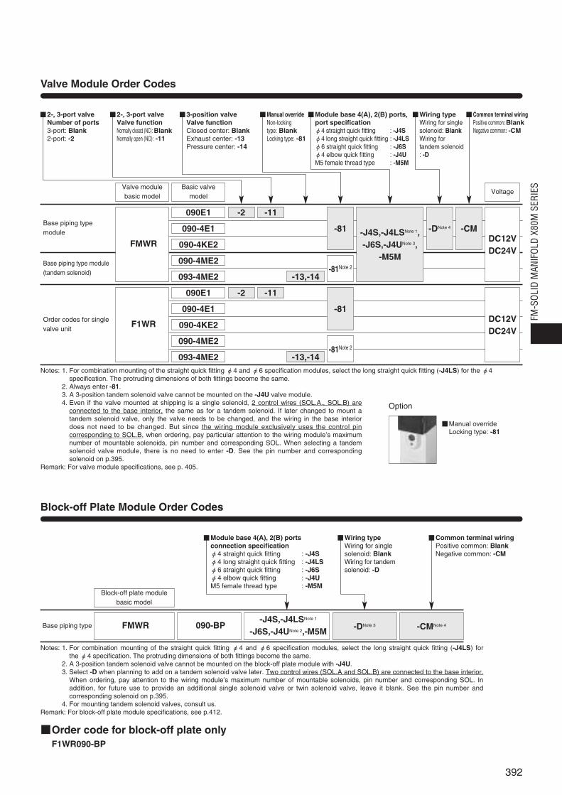
Valve Module Order Codes
Base piping typemodule
Base piping type module(tandem solenoid)
Order codes for singlevalve unit
FMWR
F1WR
090E1 -2 -11
-J4S,-J4LSNote 1,-J6S,-J4UNote 3,
-M5M
-DNote 4-81
-81
-CM
-13,-14-81Note 2
-2 -11
-13,-14-81Note 2
090-4E1
090-4KE2
090-4ME2
093-4ME2
090E1
090-4E1
090-4KE2
090-4ME2
093-4ME2
DC12VDC24V
DC12VDC24V
Notes: 1. For combination mounting of the straight quick fitting φ4 and φ6 specification modules, select the long straight quick fitting (-J4LS) for the φ4specification. The protruding dimensions of both fittings become the same.
2. Always enter -81.3. A 3-position tandem solenoid valve cannot be mounted on the -J4U valve module.4. Even if the valve mounted at shipping is a single solenoid, 2 control wires (SOL.A., SOL.B) are
connected to the base interior, the same as for a tandem solenoid. If later changed to mount atandem solenoid valve, only the valve needs to be changed, and the wiring in the base interiordoes not need to be changed. But since the wiring module exclusively uses the control pincorresponding to SOL.B, when ordering, pay particular attention to the wiring module’s maximumnumber of mountable solenoids, pin number and corresponding SOL. When selecting a tandemsolenoid valve module, there is no need to enter -D. See the pin number and correspondingsolenoid on p.395.
Remark: For valve module specifications, see p. 405.
Notes: 1. For combination mounting of the straight quick fitting φ4 and φ6 specification modules, select the long straight quick fitting (-J4LS) for theφ4 specification. The protruding dimensions of both fittings become the same.
2. A 3-position tandem solenoid valve cannot be mounted on the block-off plate module with -J4U.3. Select -D when planning to add on a tandem solenoid valve later. Two control wires (SOL.A and SOL.B) are connected to the base interior.
When ordering, pay attention to the wiring module’s maximum number of mountable solenoids, pin number and corresponding SOL. Inaddition, for future use to provide an additional single solenoid valve or twin solenoid valve, leave it blank. See the pin number andcorresponding solenoid on p.395.
4. For mounting tandem solenoid valves, consult us.Remark: For block-off plate module specifications, see p.412.
Valve modulebasic model
Basic valvemodel
Voltage
2-, 3-port valveNumber of ports3-port: Blank2-port: -2
2-, 3-port valveValve functionNormally closed (NC): BlankNormally open (NO): -11
3-position valveValve functionClosed center: BlankExhaust center: -13Pressure center: -14
Manual overrideNon-locking type: BlankLocking type: -81
Module base 4(A), 2(B) ports,port specificationφ4 straight quick fitting : -J4Sφ4 long straight quick fitting : -J4LSφ6 straight quick fitting : -J6Sφ4 elbow quick fitting : -J4UM5 female thread type : -M5M
Wiring typeWiring for singlesolenoid: BlankWiring fortandem solenoid: -D
Common terminal wiringPositive common: BlankNegative common: -CM
Block-off Plate Module Order Codes
■Order code for block-off plate only■F1WR090-BP
Base piping type FMWR 090-BP-J4S,-J4LSNote 1
-J6S,-J4UNote 2,-M5M -DNote 3 -CMNote 4
Block-off plate modulebasic model
Common terminal wiringPositive common: BlankNegative common: -CM
Wiring typeWiring for single solenoid: BlankWiring for tandem solenoid: -D
Module base 4(A), 2(B) portsconnection specificationφ4 straight quick fitting : -J4Sφ4 long straight quick fitting : -J4LSφ6 straight quick fitting : -J6Sφ4 elbow quick fitting : -J4UM5 female thread type : -M5M
Option
Manual overrideLocking type: -81
FM-S
OLID
MAN
IFOL
D X8
0M S
ERIE
S

FMCR-F100
FMCR-F200
FMCR-D250
FMCR-T070
393
SERIESFM-SOLID MANIFOLD
Wiring module model Wiring connection specification
Terminal block type Terminal block thread: M3
Remarks
FMCR-F100FMCR-F101
Flat cable connector typeMade by Sumitomo 3MBox type, with long clipPart number: 4210-00MILCSC
FMCR-F200FMCR-F201
Flat cable connector typeMade by Sumitomo 3MBox type, with long clipPart number: 4220-00MILCSC
FMCR-D250-M2.6FMCR-D250-M3FMCR-D250-UNC
D-sub connector type
Mounting threads for D-subconnector-M2.6: M2.6 thread-M3: M3 thread-UNC: #4-40-UNC thread
FMCR-G250-M2.6FMCR-G250-M3FMCR-G250-UNC
FMCR-T070
D-sub connector type
Mounting threads for D-subconnector-M2.6: M2.6 thread-M3: M3 thread-UNC: #4-40-UNC thread
Wiring Module Specifications
Module Mass g [oz.]
Wiring Modules
Features
Achieves space savings and enables lower costs by reducingwiring man-hours.
Flat cable connector typeThe range of the module includes a type with a 10-pin flat cableconnector capable of controlling up to eight solenoids, and onewith a 20-pin flat cable connector capable of controlling up to 16solenoids. Two types of pin locations are available for thewiring.
D-sub connector typeA 25-pin D-sub connector can accommodate up to 16 solenoids.Various kinds of cables and connectors are also provided tosimplify wiring connections.The FMCR-G250 is a dedicated wiring module for mountingtandem solenoid valves.
Terminal block typeA terminal block with 7 terminals can accommodate up to 6solenoids.
Type Mass
FMCR-F10□ 30 [1.06]
FMCR-F20□ 38 [1.34]
FMCR-D250-□ 44 [1.55]
FMCR-G250-□ 51 [1.80]
FMCR-T070 37 [1.31]

Flat cableconnectorD-sub connector
Flat cable connector
Terminal
(-F100)(-F101)
(-F201)
(-T070)
(-F200)(-D250)(-G250)
Details of Wiring Specifications
Solenoid Layout
Wiring Module Pin (Terminal) Locations
●FMCR-F100Flat cable connector
Notes: 1. The above pin numbers are assigned based on the solenoid valve wiringsequence for the sake of convenience.
2. The D-sub connector differs from the pin locations and numbers (marked)defined in JIS X5101 for the data circuit-terminating equipment (DCE). Cautionshould be exercised.
The flat cable connector and D-sub connector pin locations can be adapted to specifications other than those listed above.
1 2 3 4 5 6 7 8 9 10 11 12 13 14 15 16
1 2 3 4 5 6 7 8 9 10 11 12 13 14
�
Solenoid No.
Module No.
Wiring module Valve module Piping module
Triangle mark
1~8: Control pins 9, 10: Common pins(short-circuited within the module)
1
2
3
4
5
6
7
8
9
10
●FMCR-F101Flat cable connector Triangle mark
1~8: Control pins 9: (-) pin 10: (+) pin
1
2
3
4
5
6
7
8
9
10
●FMCR-F200Flat cable connector Triangle mark
1~16: Control pins17, 18: (-) pins(short-circuited within the module)19, 20: (+) pins(short-circuited within the module)
11
12
13
14
15
16
17
18
19
20
7
8
9
4
5
6
1
2
3
10
●FMCR-F201Flat cable connector Triangle mark
111~8: Control pins11~18: Control pins 9, 19: (-) pins(short-circuited within the module) 10, 20: (+) pins(short-circuited within the module)
15
5
14
4
13
3
12
2
11
1
17
7
16
9
18
8
20
10
19
6
●FMCR-D250,G250D-sub connector
1 3 5 7 9 11 13 15 17 19 21 23 25
2 4 6 8 10 12 14 16 18 20 22 24
1~16: Control pins 20, 21, 22: (-) pins(short-circuited within the module) 23, 24, 25: (+) pins(short-circuited within the module)
●FMCR-T070�
1 2 3 4 5 6 7
A, B port side
1~6: Control terminals 7: Common terminal
Solenoid sideTerminal block
Pin number
q w e r t y u i
q w e r t y u i
q w e r t y u i
o !0 !1 !2 !3 !4 !5 !6
!1 !2 !3 !4 !5 !6 !7 !8
q w e r t y
394
FM-S
OLID
MAN
IFOL
D X8
0M S
ERIE
S
Wiring module model Number of solenoids Number of pins (terminals)
FMCR-F100
FMCR-F1018 10 pins
FMCR-F200
FMCR-F20116 20 pins
FMCR-D250-M2.6
FMCR-D250-M3 16 25 pins
FMCR-D250-UNC
FMCR-G250-M2.6
FMCR-G250-M3 16 25 pins
FMCR-G250-UNC
FMCR-T070 6 7 terminals
Number of Solenoids Which Can Be Connected to aWiring Module (Possible Number of Connections)
(1 solenoid for 4E1 type, and 2 solenoids for 4KE2 type)

●Pin number and corresponding solenoid (for combination mounting of single solenoid valves and tandem solenoid valves)
X80M-ED No.1-FMCR-F200 DC24VNo.2-FMWR090-4E1-J4S DC24VNo.3-FMWR090-4E1-J4S-D DC24VNo.4~6-FMWR090-4ME2-81-J4S DC24VNo.7~9-FMWR093-4ME2-81-J4S DC24V
Pin locations
� 2�1� 3�4�5�6�7�8�9�Module No.
12
34
56
78
910
1112
1314
1516
1718
1920
●Pin number and corresponding solenoid(FMCR-G250-□)
X80MNo.1 -FMCR-G250-M2.6 DC24VNo.2,3-FMWR090-4ME2-81-J6S DC24VNo.4~7-FMWR090-4E1-J6S-D DC24VNo.8-FMWR090-BP-J6S-D DC24VNo.9-FMPR-FJ8S
Pin locations
Module No. 2 �1 � 3 �4 �5 �6 �7 �8 �9 �
123
45
67
89
1011
1213
1415
1617
1819
2021
2223
2425
Details of Wiring Specifications
395
Pin No. : 1 SOL.A First solenoid valve: Single solenoid (wiring as single solenoid)2 SOL.A
Second solenoid valve: Single solenoid (wiring as tandem solenoid: -D)Note 23 (SOL.B)Note 1
4 SOL.AThird solenoid valve: Tandem solenoid
5 SOL.B6 SOL.A
4th solenoid valve: Tandem solenoid7 SOL.B
14 SOL.A8th solenoid valve: Tandem solenoid
15 SOL.B16 Not used
17,18 (-) pins
19,20 (+) pins
Note 1: (SOL.B) shows that the wiring module control pin is assigned and the wire is connectedto the valve base interior.
}}}
}……
}
Note 2: Even if the valve mounted at shipping is a single solenoid, 2 control wires (SOL.A., SOL.B)are connected to the base interior, the same as for a tandem solenoid. If later changed tomount a tandem solenoid valve, only the valve needs to be changed, and the wiring in thebase interior does not need to be changed. But since the wiring module exclusively uses thecontrol pin corresponding to SOL.B, when ordering, pay particular attention to the wiringmodule’s maximum number of mountable solenoids, pin number and corresponding SOL.When selecting a tandem solenoid valve module, there is no need to enter -D.
Pin No. : 1 SOL.AFirst solenoid valve: Tandem solenoid
2 B3 A
Second solenoid valve: Tandem solenoid4 B5 SOL.A6 (SOL.B)Note
Third solenoid valve: Single solenoid
7 SOL.A4th solenoid valve: Single solenoid
8 (SOL.B)Note
13 (SOL.A)Note
Block-off plate14 (SOL.B)Note
20,21,22 (-) pins
23,24,25 (+) pins
Note: (SOL.A) (SOL.B) show that the control pins in the wiring module are assigned andthe wires to SOL.A and SOL.B are connected to the valve base interior.
……
……
}
}}}}
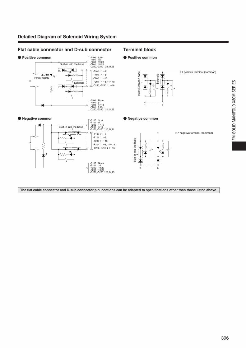
Detailed Diagram of Solenoid Wiring System
-F100:9,10�-F101:10�-F200:19,20�-F201:10,20�-D250,-G250:23,24,25��-F100:1~8�
-F101:1~8�
-F200:1~16�
-F201:1~8, 11~18�
-D250,-G250:1~16
-F100:None�-F101:9�-F200:17,18�-F201:9,19�-D250,-G250:20,21,22��
1
n
Built-in into the base
LED forPower supply
Solenoid
-F100:9,10�-F101:9�-F200:17,18�-F201:9,19�-D250,-G250:20,21,22��
-F100:None�-F101:10�-F200:19,20�-F201:10,20�-D250,-G250:23,24,25��
1
n
-F100:1~8�
-F101:1~8�
-F200:1~16�
-F201:1~8, 11~18�
-D250,-G250:1~16
Built-in into the base
Flat cable connector and D-sub connector
● Positive common
● Negative common
1 6
Bui
lt-in
into
the
base 7 positive terminal (common)
Sol
enoi
d
1 6
7 negative terminal (common)B
uilt-
in in
to th
e ba
se
Terminal block
● Positive common
● Negative common
396
FM-S
OLID
MAN
IFOL
D X8
0M S
ERIE
S
The flat cable connector and D-sub connector pin locations can be adapted to specifications other than those listed above.

FMCR Dimensions of Wiring Module (mm)
FMCR-F100/-F101Flat cable connector type
5638
151.7
70
9.5
40
Flat cable connectormade by Sumitomo 3M Ltd.4210-00M1LCSC
Power supply terminal
LED Indicator
FMCR-F200/-F201Flat cable connector type
56
38
151.7
70
9.5
40
Flat cable connectormade by Sumitomo 3M Ltd.4220-00M1LCSC
Power supply terminal
LED Indicator
FMCR-D250-M2.6/-M3/-UNCD-sub connector type
4538 15
70
9.5
43
Power supply
terminal
LED Indicator
Select from the following:-M2.6(M2.6 thread)-M3(M3 thread)-UNC(#4-40-UNC thread)
D-sub connector
FMCR-G250-M2.6/-M3/-UNCD-sub connector type
4538 15
70
9.5
43
20.4
Power supply
terminal
LED indicator
Select from the following:-M2.6(M2.6 thread)-M3(M3 thread)-UNC(#4-40-UNC thread)
D-sub connector
Note: For the -F100, the power supply terminal is not wired.
X80M-FMC
397
※Height with end block attached is +1mm [0.039in.] longerthan indicated below.

FMCR Dimensions of Wiring Module (mm)
FMCR-T070Terminal block type
4938 15
70
(55)�
M3 screw Terminal block
X80M-FMC
398
FM-S
OLID
MAN
IFOL
D X8
0M S
ERIE
S
※Height with end block attached is +1mm [0.039in.] longerthan indicated below.

Remarks: 1. The UNI-WIRE® system is a serial parallel transmission systemdeveloped jointly by NKE and KURODA PRECISIONINDUSTRIES.
2. For the details of each system, see each manufacturer’scatalog, user’s manual, etc.
3. For details on handling the corresponding manifolds, see thecorresponding Koganei user’s manuals.
Note: OMRON’s remote I/O adapter-typeDRT1-OD16X is used in the serialtransmission block for OMRON’sCompoBus/D. For details, seeOMRON’s catalog, user’s manual,etc.
X80MS1-A1-LNo.1~8--FMWR090-4ME2-81-J4S DC24VNo.9--FMPR-PR01S
30.6 6
B
A
B
A
PR
139.2
R
P
615
4-φ3.4
66.9
708
4.6
(3.5)�
22.5
63
(3)�
A
B
A
B
A B0
A
B
A
B
A B0
A
B
A
B
A B0
A
B
A
B
A B0
A
B
A
B
A B0
A
B
A
B
A B0
A
B
A
B
A B0
A
B
A
B
A B0
102.6
YS
1A1L
HOLDNC
84
21
BS-
BDL
BS+BDH
FG
PWR
COMMERR
MA
DE
IN JA
PA
N
8×10.2(Pitch)
3, 5(R)Port
2(B)Port
4(A)Port
1(P)Port
Example of Manifold Configuration for Compact Serial Transmission System (mm)
Features
A manifold with compact serial transmission block, correspond-ing to each manufacturer’s serial transmission system.
399
SERIESFM-SOLID MANIFOLD
Compact Serial Transmission System
For NKE, KURODA PRECISION INDUSTRIES UNI-WIRE® System
For Mitsubishi Electric MELSECNET/MINI-S3
For Mitsubishi Electric MELSEC I/O LINK
For Mitsubishi Electric CC-Link
For Fuji Electric FA Components & Systems T Link Mini
For OMRON CompoBus/S
For OMRON SYSBUS Wire System
For OMRON B7A Link Terminal
For SUNX S-LINK
For OMRON CompoBus/DNote
For KEYENCE KZ-R
For KOYO ELECTRONICS INDUSTRIES SA Bus
Configuration Example1

X80MS1-A1-LNo.1~16 -- FMWR090-4E1-J6S DC24VNo.17-- FMPR-PR01S
YS
1A1L
220.8
(3)�184.2
7011
(3.5)�
22.5
63
66 1530.6
HOLDNC
84
21
BS-
BDL
BS+BDH
FG
PWR
COMMERR
66.9
B
A
B
A
PR
R
P
MA
DE
IN JA
PA
N
4-φ3.4
16×10.2(Pitch)
3, 5(R)Port
2(B)Port
4(A)Port
1(P)Port
Example of Manifold Configuration for Compact Serial Transmission System (mm)
X80MS1-91-L-DNNo.1-- FMCR-F201 DC24VNo.2~17 -- FMWR090-4E1-J6S DC24VNo.18-- FMPR-PR01S
P
R
PR
A
B
A
B
81
(5)�
(5)�8
5.5
35
(71.5)�
40
(44.5)�
1239
(53.5)�
50
85
348
7663
199.2
211.9
OUT
NSMS
REMOTE ADAPTER 24VDCDRT1-OD16X
OMRON remote adapterSerial transmission block
Model: DRT1-OD16X
3, 5(R)Port
2(B)Port
4(A)Port
1(P)Port
400
FM-S
OLID
MAN
IFOL
D X8
0M S
ERIE
S
Configuration Example 2
Configuration Example 3 For CompoBus/D

●For OMRON SYSBUS Wire SystemTransmission block specification: -21
●For Mitsubishi Electric MELSECNET/MINI-S3Transmission block specification: -11
●For UNI-WIRE® SystemTransmission block specification: -01 (16 outputs), -02 (8 outputs)
Compact Serial Transmission Block, Terminal Block (LED) Names
LED indicatorIndicator Description
•Lights up when power is turned onPOWER •Flashes during voltage drops or
when over current (a short circuit)
SEND •Flashes during normal transmission•Lights up or shuts off during faulty transmission
LED indicatorIndicator Description
RUN •Lights up when transmission is normal, and the PCis in operations mode or monitor mode
T/R •Flashes during normal transmission
ERR •Lights up during standby or faulty transmission•Shuts off during faults (during watchdog timer fault)
LED indicatorIndicator Description
PWR •Lights up when power is turned on
RUN •Lights up for normal data communication with master station
SD •Flashes during sending data
RD •Flashes during receiving data
ERR •Lights up when data receiving error occurs,shuts off for normal communication
●For OMRON B7A Link TerminalTransmission block specification: -31 (standard type), -32 (high speed type)
Remarks●Connection method: 1 to 1(Transmission block spec.) Standard type (-31) High speed type (-32)Transmission delay time Max.31ms Max.5msTransmission distance Max.500m Max.100m※For details of the B7A Link Terminal, see the
OMRON catalog, user’s manual, etc.
●Number of outputs per blockMaximum of 16 solenoids
●Error output specificationsOutput mode: NPN open collectorRated load voltage: DC24VOutput current: Sink current MAX. 40mA
●Related materials: User’s manual, document No.HV008
●For KOYO ELECTRONICS INDUSTRIES SA BusTransmission block specification: -41 (16 outputs), -42 (8 outputs)
LED indicatorIndicator Description
PWR •Lights up when power is turned on
ERR •Lights up during faulty transmission
LED indicatorIndicator Description
Power •Lights up when power is turned on
Error •Lights up during faulty transmission or other faults
●For SUNX S-LINKTransmission block specification: -51 (16 outputs), -52 (8 outputs)
LED indicatorIndicator Description
POWER •Lights up when power is turned on
SEND •Flashes during normal transmission•Lights up or shuts off during faulty transmission
Remarks※For details of the SA Bus system, see the KOYO
ELECTRONICS INDUSTRIES catalog, user’smanual, etc.
●Number of outputs per block16 solenoids (transmission block specification: -41)8 solenoids (transmission block specification: -42)
●Related materials: User’s manual, document No.HV009
Remarks※For details of the S-LINK System, see the SUNX
catalog, user’s manual, etc.
●Number of outputs per block16 solenoids (transmission block specification: -51)8 solenoids (transmission block specification: -52)
●Related materials: User’s manual, document No.HV010
ON
1 2 3 4 5 6 7 8
DG 24V DG0V 24V0V
SENDPOWER
SHLD L24V
ON1
23
45
67
8
L+ L-24V 0V
PWR ERR
LOADOFF HOLD
ERR SIG
Station number setting switchOutput selecting switch in faulty operationSwitch for address setting and output processing setting during error occurrence
POWER ERROR
ON
1 2 3 4 5 6 7 8
D G 24V D0V 24V 0V
POWER SEND
24V 0V
09
87
6 54
32
13 E 09
87
6 54
32
13 E
RDA RDB SDA SDB SG FG
PWR RUN ERR
S D R D ONOFF
ADDRESS×10 ×1
+�-� 24V 0V
O N1 2 3 4 5 6
RUNT/RERR
TERM
ONOFF
G FG
Address setting switch Rotary switch for station number setting
E. C. MODE switch
Dip switch for various settings
End station setting switch
401
Compact Serial Transmission System Specifications
General SpecificationsVoltage
Operating temperature range
Vibration resistance
Shock resistance
●For details of specifications, see the user’s manuals (see below).
DC24V ±10%
5~50°C [41~122°F]
49.0m/s2 {5.0G} (Conforms to JIS C 0911)
98.1m/s2 {10.0G} (Conforms to JIS C0912)
Remarks※The UNI-WIRE® System is a serial parallel transmission
system developed jointly by NKE and KURODAPRECISION INDUSTRIES. For details of the UNI-WIRE System, see the NKE or KURODA PRECISIONINDUSTRIES catalog, user’s manual, etc.
●Number of outputs per block16 solenoids (transmission block specification: -01)8 solenoids (transmission block specification: -02)
●Related materials: User’s manual, document No. HV005
Remarks●Master station: MELSEC-A series
AJ71PT32-S3, AJ71T32-S3, A2CCPU/A2CJCPU,A1SJ71PT32-S3, link sub-stations up to a maximum of 64stations, and link I/O numbers up to a maximum of 512.※For details, see the Mitsubishi Electric’s sequencer
MELSEC-A series catalog, user’s manual, etc.●Number of outputs per block
Maximum of 16 solenoids※Since the block is equivalent to 2 stations, if sub-
stations are entirely composed of the blocks, themaximum becomes 32 units.
●Related materials: User’s manual, document No. HV006
Remarks●Master station unit: SYSMAC-C (CV) series
C200H-RM201, C500-RM201※For details, see the OMRON’s programmable controller
SYSMAC C(CV) series catalog, user’s manual, etc.
●Number of outputs per blockMaximum of 16 solenoids
●Related materials: User’s manual, document No. HV007
24V 0VS1 S2 SD FG
PWR ALM
ON OFF HOLD CLEAR
24V 0V
09
87
6 54
32
13 E
S+� S-� RUN FG
POWER/ERROR
ERROR MODE
ADDRESS
24V 0V
0 1 2
34
5
6
789A
BC
DE
F3 E
DATA DG FG
PW RUN ERR.
S D R D
ST. NO.0
9
87
6 54
32
13 E 09
87
6 54
32
13 E
ADDRESS×10 ×1
ON/OFF switch for terminating resistance
Address setting switchStation number setting switch Station number setting switch
Error holdiing switch
1 10 ON
MS NS
Transmission connector Power supply terminal for internal circuit
Dip switch
O N1 2 3 4 5 6
PWR COMM ERR
FGBS-�BS+� BDH BDL
Dip switch for various settings
DB DA
0
8
6 4
2
0
8
6 4
2
0
8
6 4
2
24G +24V SLD DG(FG)�
PW L RUN L ERR.
S D R D
HOLD CLEAR
B RATE STATION NO.×10 ×1
Station number setting switchTransmission speed setting switch
HOLD/CLEAR switch
402
FM-S
OLID
MAN
IFOL
D X8
0M S
ERIE
S
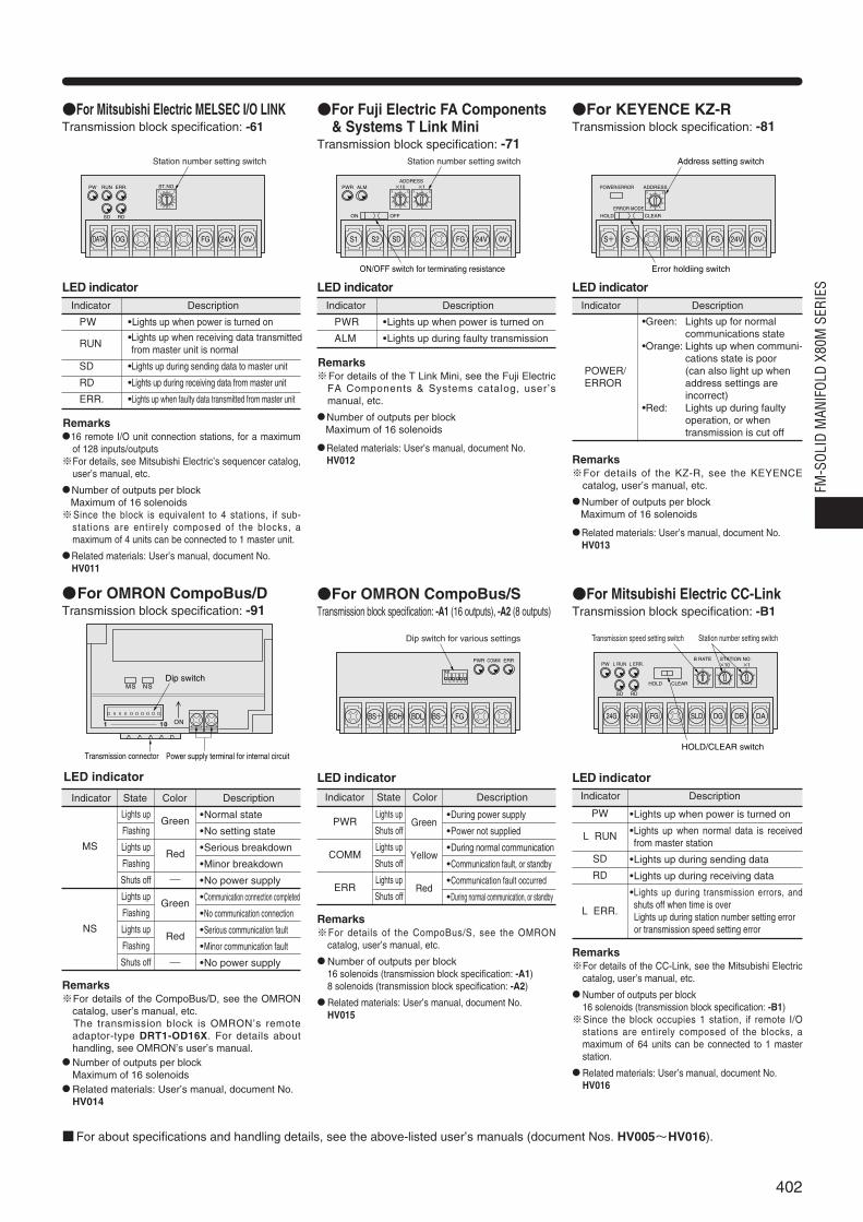
●For Fuji Electric FA Components & Systems T Link Mini
Transmission block specification: -71
Remarks※For details of the T Link Mini, see the Fuji Electric
FA Components & Systems catalog, user ’smanual, etc.
●Number of outputs per blockMaximum of 16 solenoids
●Related materials: User’s manual, document No.HV012
●For Mitsubishi Electric MELSEC I/O LINKTransmission block specification: -61
Remarks●16 remote I/O unit connection stations, for a maximum
of 128 inputs/outputs ※For details, see Mitsubishi Electric’s sequencer catalog,
user’s manual, etc.
●Number of outputs per blockMaximum of 16 solenoids※Since the block is equivalent to 4 stations, if sub-
stations are entirely composed of the blocks, amaximum of 4 units can be connected to 1 master unit.
●Related materials: User’s manual, document No.HV011
●For OMRON CompoBus/D Transmission block specification: -91
Remarks※For details of the CompoBus/D, see the OMRON
catalog, user’s manual, etc.※The transmission block is OMRON’s remote
adaptor-type DRT1-OD16X. For details abouthandling, see OMRON’s user’s manual.
●Number of outputs per blockMaximum of 16 solenoids
●Related materials: User’s manual, document No.HV014
Lights up
Flashing
Lights up
Flashing
Shuts off
Lights up
Flashing
Lights up
Flashing
Shuts off
LED indicator
Indicator State Color Description
MS
NS
•Normal state
•No setting state
•Serious breakdown
•Minor breakdown
•No power supply
•Communication connection completed
•No communication connection
•Serious communication fault
•Minor communication fault
•No power supply
Green
Red
Green
Red
●For KEYENCE KZ-RTransmission block specification: -81
LED indicatorIndicator Description
PWR •Lights up when power is turned on
ALM •Lights up during faulty transmission
LED indicatorIndicator Description
•Green: Lights up for normal communications state
•Orange: Lights up when communi-cations state is poor
POWER/ (can also light up when ERROR address settings are
incorrect)•Red: Lights up during faulty
operation, or when transmission is cut off
LED indicatorIndicator Description
PW •Lights up when power is turned on
RUN •Lights up when receiving data transmittedfrom master unit is normal
SD •Lights up during sending data to master unit
RD •Lights up during receiving data from master unit
ERR. •Lights up when faulty data transmitted from master unit
Remarks※For details of the KZ-R, see the KEYENCE
catalog, user’s manual, etc.
●Number of outputs per blockMaximum of 16 solenoids
●Related materials: User’s manual, document No.HV013
●For OMRON CompoBus/STransmission block specification: -A1 (16 outputs), -A2 (8 outputs)
Remarks※For details of the CompoBus/S, see the OMRON
catalog, user’s manual, etc.
●Number of outputs per block16 solenoids (transmission block specification: -A1)8 solenoids (transmission block specification: -A2)
● Related materials: User’s manual, document No.HV015
Lights up
Shuts off
Lights up
Shuts off
Lights up
Shuts off
Green
Yellow
Red
LED indicator
Indicator State Color Description
PWR
COMM
ERR
•During power supply
•Power not supplied
•During normal communication
•Communication fault, or standby
•Communication fault occurred
•During normal communication, or standby
●For Mitsubishi Electric CC-LinkTransmission block specification: -B1
LED indicatorIndicator Description
PW
L RUN
SD
RD
L ERR.
•Lights up when power is turned on
•Lights up when normal data is receivedfrom master station
•Lights up during sending data
•Lights up during receiving data
•Lights up during transmission errors, andshuts off when time is overLights up during station number setting erroror transmission speed setting error
Remarks※For details of the CC-Link, see the Mitsubishi Electric
catalog, user’s manual, etc.
● Number of outputs per block16 solenoids (transmission block specification: -B1)※Since the block occupies 1 station, if remote I/O
stations are entirely composed of the blocks, amaximum of 64 units can be connected to 1 masterstation.
● Related materials: User’s manual, document No.HV016
■For about specifications and handling details, see the above-listed user’s manuals (document Nos. HV005~HV016).

FMPR-FJ8S
FMPR-FJ8L
FMPR-FR01
FMPR-PR01S
403
SERIESFM-SOLID MANIFOLD
Model Mass
FMPR-FJ8S 36 [1.27]
FMPR-FJ8L 42 [1.48]
FMPR-FR01 37 [1.31]
FMPR-PR01S 50 [1.76]
Model 1(P) port specification 3, 5(R) port specification
FMPR-FJ8S With straight quick fitting for φ8 tubeWith built-in muffler
FMPR-FJ8L With elbow quick fitting for φ8 tube
FMPR-FR01 Rc1/8 (female thread specification)(exhausts to atmosphere)
FMPR-PR01S Rc1/8 (female thread specification) Rc1/8 (female thread specification,3, 5(R) and PR (captured exhausts))
Piping Modules
Piping Module Specifications
FeaturesSelectable according to piping requirements, for reducing of pipingwork, and easier maintenance.
Built-in quick fitting typeThe 1(P) port offers 2 types (straight and elbow types) of built-inquick fittings for theφ8 tube. The 3, 5(R) port is equipped with abuilt-in muffler.
1(P) port female thread typeThe 1(P) port has an Rc1/8 female thread.The 3, 5(R) port has a built-in muffler.
All port female thread typeThe 1(P) port has an Rc1/8 female thread.The 3, 5(R) port and PR port have captured exhausts.
Module Mass g [oz.]

FMPR-FJ8S FMPR-FJ8LBuilt-in straight quick fitting type Built-in elbow quick fitting type
38
15
P
70
6515
30
Exhaust outlet
Quick fitting
1(P)Port
38
31.5 23
15
P
6516.5
Exhaust outlet
Quick fitting1(P)Port
FMPR-FR01 FMPR-PR01S1(P) port female thread type All port female thread type
38
Rc1/8
15
P
830
14(Width across flats)
Exhaust outlet
1(P)Port
38
3-Rc1/815
P
R
PR
11
70
1830
3, 5(R)Port
1(P)Port
FMPR Dimensions of Piping Module (mm)
X80M-FMP
404
FM-S
OLID
MAN
IFOL
D X8
0M S
ERIE
S
※Height with end block attached is +1mm [0.039in.] longerthan indicated below.
FMWR090E1
FMWR090-4KE2
FMWR090-4E1
405
SERIESFM-SOLID MANIFOLD
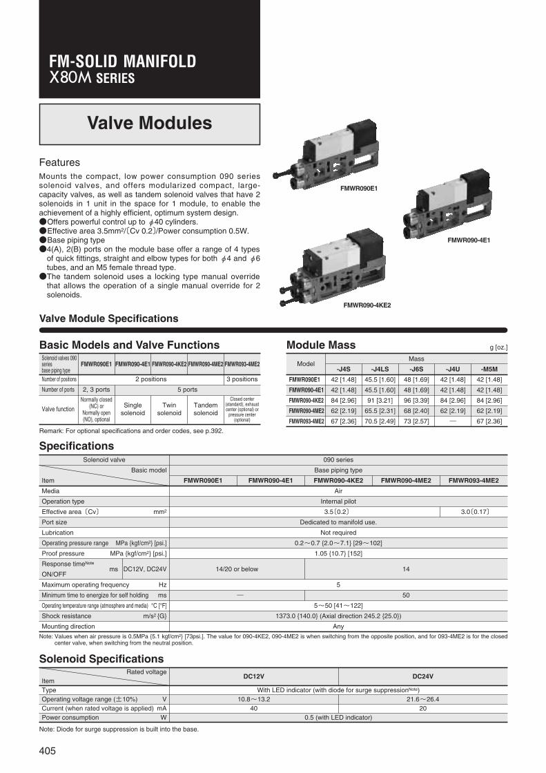
Valve Modules
FeaturesMounts the compact, low power consumption 090 seriessolenoid valves, and offers modularized compact, large-capacity valves, as well as tandem solenoid valves that have 2solenoids in 1 unit in the space for 1 module, to enable theachievement of a highly efficient, optimum system design.●Offers powerful control up to φ40 cylinders.●Effective area 3.5mm2/〔Cv 0.2〕/Power consumption 0.5W.●Base piping type●4(A), 2(B) ports on the module base offer a range of 4 types
of quick fittings, straight and elbow types for both φ4 and φ6tubes, and an M5 female thread type.●The tandem solenoid uses a locking type manual override
that allows the operation of a single manual override for 2solenoids.
Solenoid valves 090seriesbase piping type
FMWR090E1 FMWR090-4E1 FMWR090-4KE2 FMWR090-4ME2 FMWR093-4ME2
Number of positions 2 positions 3 positions
Number of ports 2, 3 ports 5 ports
Valve function
Remark: For optional specifications and order codes, see p.392.
Normally closed(NC) or
Normally open(NO), optional
Singlesolenoid
Twinsolenoid
Tandemsolenoid
Closed center(standard), exhaustcenter (optional) or
pressure center(optional)
Valve Module Specifications
Module Mass g [oz.]Basic Models and Valve Functions
ModelMass
-J4S -J4LS -J6S -J4U -M5M
FMWR090E1 42 [1.48] 45.5 [1.60] 48 [1.69] 42 [1.48] 42 [1.48]
FMWR090-4E1 42 [1.48] 45.5 [1.60] 48 [1.69] 42 [1.48] 42 [1.48]
FMWR090-4KE2 84 [2.96] 91 [3.21] 96 [3.39] 84 [2.96] 84 [2.96]
FMWR090-4ME2 62 [2.19] 65.5 [2.31] 68 [2.40] 62 [2.19] 62 [2.19]
FMWR093-4ME2 67 [2.36] 70.5 [2.49] 73 [2.57] ― 67 [2.36]
SpecificationsSolenoid valve 090 series
Basic model Base piping type
Item FMWR090E1 FMWR090-4E1 FMWR090-4KE2 FMWR090-4ME2 FMWR093-4ME2
Media Air
Operation type Internal pilot
Effective area〔Cv〕 mm2 3.5〔0.2〕 3.0〔0.17〕
Port size Dedicated to manifold use.
Lubrication Not required
Operating pressure range MPa {kgf/cm2} [psi.] 0.2~0.7 {2.0~7.1} [29~102]
Proof pressure MPa {kgf/cm2} [psi.] 1.05 {10.7} [152]
Response timeNote
ms DC12V, DC24V 14/20 or below 14ON/OFF
Maximum operating frequency Hz 5
Minimum time to energize for self holding ms ― 50
Operating temperature range (atmosphere and media) °C [°F] 5~50 [41~122]
Shock resistance m/s2 {G} 1373.0 {140.0} (Axial direction 245.2 {25.0})
Mounting direction Any
Note: Values when air pressure is 0.5MPa {5.1 kgf/cm2} [73psi.]. The value for 090-4KE2, 090-4ME2 is when switching from the opposite position, and for 093-4ME2 is for the closedcenter valve, when switching from the neutral position.
Solenoid SpecificationsRated voltage
DC12V DC24VItemType With LED indicator (with diode for surge suppressionNote)Operating voltage range (±10%) V 10.8~13.2 21.6~26.4Current (when rated voltage is applied) mA 40 20Power consumption W 0.5 (with LED indicator)
Note: Diode for surge suppression is built into the base.

Cylinder Operating Speed
Flow Rate
t1 t2 t3
Cylinder start
Cylinder stop
Cushioning impact
Solenoid valve
energized
Cyl
inde
r st
roke
Time
1200
1000
800
600
400
200
06010 20 30 40 50 70
φ20φ25φ32φ40
%�
mm/sMaximum operating speed
Load ratio
Max
imum
ope
ratin
g sp
eed
0.5MPa
Load
FMWR090-4E1 FMWR090-4ME2
φ40φ32φ25φ20
6010 20 30 40 50 70%�
s 1.00.90.80.70.60.50.40.30.20.10
Delay time
Load ratio
Del
ay ti
me
How to read the graphWhen the supply pressure is 0.5MPa [73psi.] and flowrate is 170R/min [6.0ft.3/min.] (ANR), the valve outletpressure becomes 0.4MPa [58psi.].
MPa0.7
0.70.6
0.50.5
0.4
0.3
0.2
0.1
060 120 180 240 300
0.40.3
0.2
0.1
0.6
FMWR090E1FMWR090-4E1FMWR090-4KE2FMWR090-4ME2
Flow rate
Val
ve o
utle
t pre
ssur
e
R/min (ANR)
Supply pressure(MPa)
406
FM-S
OLID
MAN
IFOL
D X8
0M S
ERIE
S
Cylinder operating speed
FMWR090-4E1FMWR090-4ME2Measurement conditions●Air pressure: 0.5MPa{5.1kgf/cm2} [73psi.]●Piping inner diameter and length: φ4×1000mm [39in.]●Fitting:φ6 straight quick fitting (-J6S)
●Load ratio=Load
Cylinder theoretical thrust(%)
●Cylinder stroke: 150mm [5.91in.] for φ20~φ40
To obtain the time required for thecylinder to complete 1 stroke, addcylinder’s delay time t1 (time betweenenergizing of the solenoid valve andactual starting of the cylinder), to thecylinder’s max. speed operating time t2.When a cushion is used, add thecushioning time t3, to the abovecalculation. The standard cushioningtime t3 is approximately 0.2 seconds.
1mm/s = 0.0394in./sec.
2(B)Port
4(A)Port
2-M5×0.8 female thread type
5.310.4
3
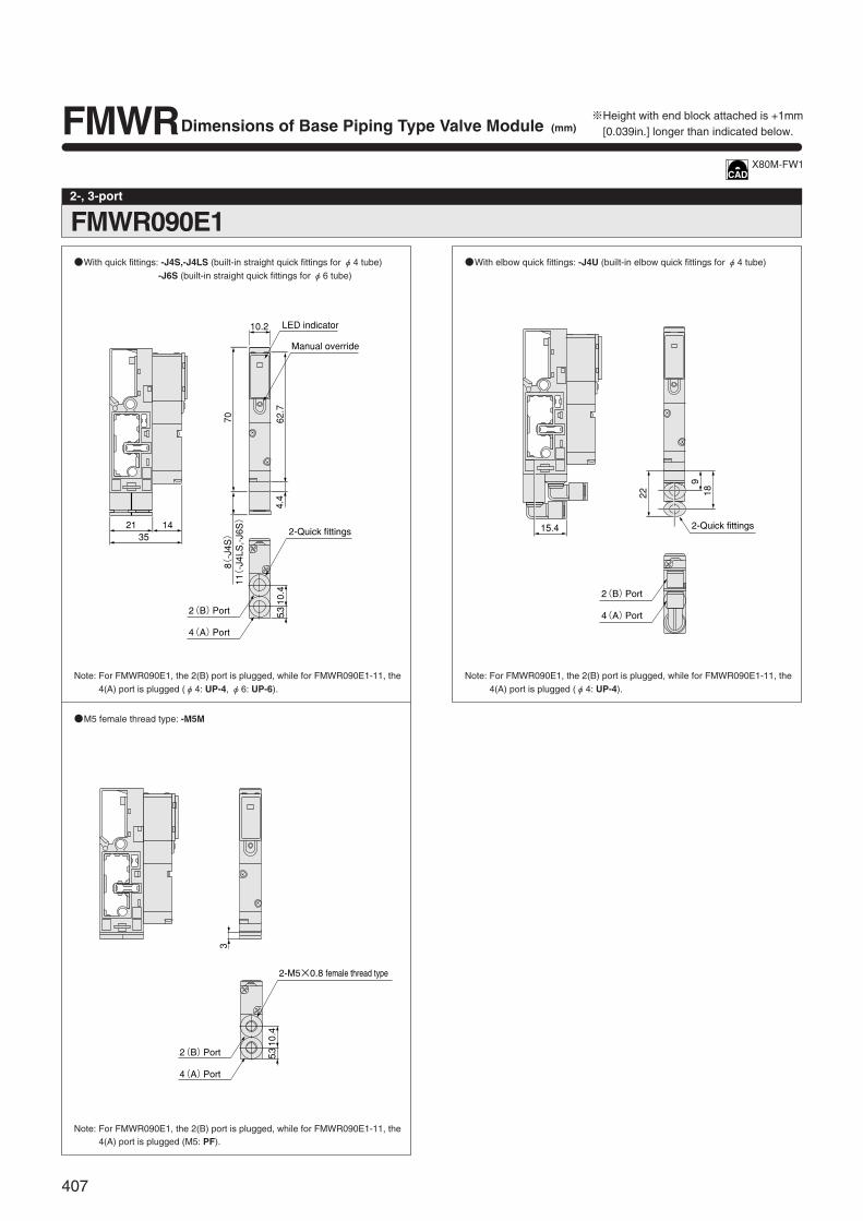
FMWRDimensions of Base Piping Type Valve Module (mm)
FMWR090E12-, 3-port
21 1435
10.2
�
70 62.7
4.4
10.4
5.3
8(-J4S)�
11(-J4LS,-J6S)�
LED indicator
Manual override
2-Quick fittings
2(B)Port
4(A)Port
●With quick fittings: -J4S,-J4LS (built-in straight quick fittings for φ4 tube)
-J6S (built-in straight quick fittings for φ6 tube)
Note: For FMWR090E1, the 2(B) port is plugged, while for FMWR090E1-11, the4(A) port is plugged (φ4: UP-4, φ6: UP-6).
●M5 female thread type: -M5M
Note: For FMWR090E1, the 2(B) port is plugged, while for FMWR090E1-11, the4(A) port is plugged (M5: PF).
2(B)Port
4(A)Port
2-Quick fittings15.4
22
918
●With elbow quick fittings: -J4U (built-in elbow quick fittings for φ4 tube)
Note: For FMWR090E1, the 2(B) port is plugged, while for FMWR090E1-11, the4(A) port is plugged (φ4: UP-4).
X80M-FW1
407
※Height with end block attached is +1mm[0.039in.] longer than indicated below.

2(B)Port
4(A)Port
2-M5×0.8 female thread type
3
10.4
5.3
※Height with end block attached is +1mm [0.039in.] longer than indicated below.
FMWR090-4E1Single solenoid valve
2(B)Port
4(A)Port
2-Quick fittings
LED indicator
Manual override
8(-J4S)�
11(-J4LS,-J6S)�
21 1435
10.2
70 62.7
4.4
10.4
5.3
●With quick fittings: -J4S,-J4LS (built-in straight quick fittings for φ4 tube)
-J6S (built-in straight quick fittings for φ6 tube)
●M5 female thread type: -M5M
2(B)Port
4(A)Port
2-Quick fittings15.4
91822
●With elbow quick fittings: -J4U (built-in elbow quick fittings for φ4 tube)
X80M-FW1
408
FM-S
OLID
MAN
IFOL
D X8
0M S
ERIE
S

2(B)Port
4(A)Port
4-M5×0.8 female thread typeRight side 4(A), 2(B) ports are plugged.
(M5: PF)
33
10.2
5.310.4
FMWRDimensions of Base Piping Type Valve Module (mm)
FMWR090-4KE2Twin solenoid valve
2(B)Port
4(A)Port
2-LED indicators
2-Manual overrides
4-Quick fittingsRight side 4(A), 2(B) ports are plugged.21 14
35
20.4
70 62.7
4.4
10.4
5.3
8(-J4S)�
11(-J4LS,-J6S)�
�
10.2
φ4:UP-4�φ6:UP-6
●With quick fittings: -J4S, -J4LS (built-in straight quick fittings for φ4 tube)
-J6S (built-in straight quick fittings for φ6 tube)
●M5 female thread type: -M5M
2(B)Port
4(A)Port
4-Quick fittingsRight side 4(A), 2(B) ports are plugged.
(φ4: UP-4)
15.4
189
22
●With elbow quick fittings: -J4U (built-in elbow quick fittings for φ4 tube)
X80M-FW2
409
※Height with end block attached is +1mm[0.039in.] longer than indicated below.

A
B
BA0
A B
3 4.4
10.4
5.3
2-M5×0.8 female thread type
2(B)Port
4(A)Port
※Height with end block attached is +1mm [0.039in.] longer than indicated below.
FMWR090-4ME2Tandem solenoid valve
21 2454.8
10.4
4.4
70.2
5.3
8(-J4S)�
11(-J4LS,-J6S)�
10.2
A
A B
B
BA0
2(B)Port
4(A)Port
2-Quick fittings
LED Indicators
Manual override
●With quick fittings: -J4S, -J4LS (built-in straight quick fittings for φ4 tube)
-J6S (built-in straight quick fittings for φ6 tube)
●M5 female thread type: -M5M
15.4
22
918
4.4
A
A B
B
BA0
2-Quick fittings
2(B)Port
4(A)Port
●With elbow quick fittings: -J4U (built-in elbow fittings for φ4 tube)
410
FM-S
OLID
MAN
IFOL
D X8
0M S
ERIE
S

3
A
B
BA0
BA
10.4
5.3
2-M5×0.8 female thread type
2(B)Port
4(A)Port
FMWR093-4ME2Tandem solenoid valve
8(-J4S)�
11(-J4LS,-J6S)�
2.5(-J4S)�
5.5(-J4LS, -J6S)�
21 2454.8
74.6
10.280.1
10.4
5.3
A
A B
B
BA0
LED indicators
Manual override
2-Quick fittings
2(B)Port
4(A)Port
●With quick fittings: -J4S, -J4LS (built-in straight quick fittings for φ4 tube)
-J6S (built-in straight quick fittings for φ6 tube)
●M5 female thread type: -M5M
FMWRDimensions of Base Piping Type Valve Module (mm)
411
※Height with end block attached is +1mm[0.039in.] longer than indicated below.

FMWR090-BP
412
FM-S
OLID
MAN
IFOL
D X8
0M S
ERIE
S
SERIESFM-SOLID MANIFOLD
Block-off Plate Module
Block-off Plate Module Specifications
Module Mass g [oz.]
Features
Offers an additional valve mounting space, to provide for the futureinstallation of add-on valves.
MassModel
-J4S -J4LS -J6S -J4U -M5M
FMWR090-BP 24 [0.85] 27.5 [0.97] 30 [1.06] 24 [0.85] 24 [0.85]

x
x
2122.6
10.2
703
62.5
4.5
10.4
5.3
2-M5×0.8 female thread type
2(B)Port
4(A)Port
x
x
15.4
1822
9
2-Quick fittings
2(B)Port
4(A)Port
FMWR090-BPBlock-off plate module
x
x
2122.6
10.2
708(-J4S)
11( -J4LS)
62.5
4.5
10.4
5.3
2-Quick fittings
2(B)Port
4(A)Port
●With φ4 straight quick fittings: -J4S (built-in straight quick fittings)-J4LS (built-in long straight quick fittings)
●With φ4 elbow quick fittings: -J4U (built-in elbow quick fittings)
x
x
2122.6
10.2
70
�
11
62.5
4.5
10.4
5.3
2-Quick fittings
2(B)Port
4(A)Port
●Withφ6 straight quick fittings: -J6S (built-in straight quick fittings)
●M5 female thread type: -M5M
Dimensions of Block-off Plate Module (mm)
X80M-FW3
413
※Height with end block attached is +1mm [0.039in.]longer than indicated below.

X80M X80M-DN
X80M-ER X80M-UL
414
SERIESFM-SOLID MANIFOLD
Model Mass
X80M 30 [1.06]
X80M-ER 47 [1.66]
X80M-EL 47 [1.66]
X80M-ED 64 [2.26]
X80M-UR 80 [2.82]
X80M-UL 80 [2.82]
X80M-UD 130 [4.59]
X80M-DN 118 [4.16] (88 [3.10])Note
Note: Figures in parentheses ( ) are the mass for the DIN rail mounting bracket only.
End Blocks
End Block Mass
Module Mass g [oz.]
Features
●End block piping types are also in the product range.
●Seven types offer minimum installation space.
●An end block with DIN rail mounting brackets is also availableas an option.
FM-S
OLID
MAN
IFOL
D X8
0M S
ERIE
S
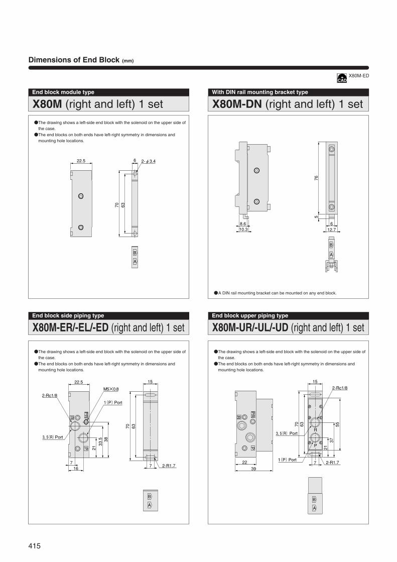
X80M (right and left) 1 setEnd block module type With DIN rail mounting bracket type
X80M-ER/-EL/-ED (right and left) 1 setEnd block side piping type
B
A
6
6370
22.5 2-φ3.4
●The drawing shows a left-side end block with the solenoid on the upper side ofthe case.●The end blocks on both ends have left-right symmetry in dimensions and
mounting hole locations.
●A DIN rail mounting bracket can be mounted on any end block.
B
A
70 63
2133.5 38
R
PPR
22.5
2-Rc1/8M5×0.8
15
7716
2-R1.7
3, 5(R)Port
1(P)Port
●The drawing shows a left-side end block with the solenoid on the upper side ofthe case.●The end blocks on both ends have left-right symmetry in dimensions and
mounting hole locations.
X80M-DN (right and left) 1 set
X80M-UR/-UL/-UD (right and left) 1 setEnd block upper piping type
B
A
765
612.7
8.610.3
B
A
70 63
2137
55
R
PPR
2-Rc1/8
7
15
R
P
2239
2-R1.7
3, 5(R)Port
1(P)Port
●The drawing shows a left-side end block with the solenoid on the upper side ofthe case.●The end blocks on both ends have left-right symmetry in dimensions and
mounting hole locations.
Dimensions of End Block (mm)
X80M-ED
415

6
32-φ3.4
15×m+10.2×nNote1 Note2
15
2-R1.77
X80M-ER
615×m+10.2×n15
2-R1.7 7 3
2-φ3.4
X80M-EL
15×m+10.2×n15
2-R1.7 7
15
2-R1.77
X80M-ED
6
32-φ3.4
15×m+10.2×n 15
2-R1.77
R
P
3, 5(R)Port
1(P)Port
X80M-UR
3
15×m+10.2×n 6 2-φ3.415
2-R1.7 7
R
P
3, 5(R)Port
1(P)Port
X80M-UL
15×m+10.2×n15
2-R1.7 7
R
P
15
2-R1.77
R
P
3, 5(R)Port
1(P)Port
X80M-UD
Notes: 1. “m” is the number of wiring modules and piping modules.2. “n” is the number of valve modules and block-off plate modules.
Dimensions of Various End Block Piping Types (mm)
416
FM-S
OLID
MAN
IFOL
D X8
0M S
ERIE
S

Handling Instructions and Precautions
Solenoid for X80M series
PUSH
(+)�
(-)�
DC12VDC24V
COM
LED indicator: Red
LED indicator(Light Emitting Diode)
(ー)�
(+)�
(ー)�
DC12VDC24V
COM
A
B
LED indicator(Light Emitting Diode)
LED indicator: Red
COM(+)�
1
2
Built-in in the base
Solenoid A
Solenoid B
417
Internal circuit
●●DC12V, DC24V
●DC12V, DC24V
Tandem solenoid
Wiring diagram in the base interior for thewiring of tandem solenoid (-D)
Single solenoid
Cautions: 1.Do not apply megger between the pins.2.The solenoid will not short circuit even if the
wrong polarity is applied, but the valve willnot operate.
3.Avoid energizing simultaneously. The valvecould enter a neutral position.
4.Leakage current inside the circuit couldresult in failure of the solenoid valve toreturn, or in other erratic operation. Alwaysuse it within the range of the allowableleakage current. If circuit conditions, etc.cause the leakage current to exceed theallowable leakage current, consult us.
Caution: Contact us for COM (-)
Manual override
Non-locking type
To operate the manual override, press it all theway down. For the single solenoid, the valveworks the same as when in the energized stateas long as the manual override is pushed down,and returns to the rest position upon release.For the twin solenoid, pressing the manual over-ride on the 12(S1) side switches the 12(S1) toenter the energized position, and the unitremains in that position even after the manualoverride is released. To return it to the normalposition, operate the manual override on the14(S2) side. This is the same for the solenoid14(S2).
Locking type
To lock the button, use a small screwdriver topush down on the manual override button all theway and turn it clockwise 45 degrees.When locked, turning the manual override button45 degrees in the counterclockwise directionreturns it to its normal position, and releases thelock.
Cautions: 1.The 090 series valves are pilot typesolenoid valves, the manual overridecannot switch the main valve without airsupplied from the 1(P) port.
2.Always release the lock of the locking typemanual override before commencingnormal operation.
3.Do not attempt to operate the manualoverride with a pin or other object havingan extremely fine tip. It could damage themanual override button.
4.Do not turn the manual override more thanneeded. It could result in defectiveoperation.

Important Precautions
Twin solenoid valve
Plug ( )For φ4 quick fitting:UP4 For φ6 quick fitting:UP6 For M5 female thread:PF
418
FM-S
OLID
MAN
IFOL
D X8
0M S
ERIE
S
Model
Solenoid valves 090 series
Number of valves
6
Mounting
1. While any mounting direction is allowed,avoid mountings that twist the manifold.
2. When connecting piping to manifolds orother devices, flush the tubes completely byblowing compressed air before piping.
2. If metal chips, sealing tape, or rustgenerated during piping work enter, it maycause a malfunction such as an air leakage.
3. When mounting a valve unit inside thecontrol panels, or when the operationrequires long energizing periods, considerproviding heat radiation.
4. The valve module cannot be operated withthe 4(A), 2(B) ports open to the atmosphere.
Piping
1. For the 1(P) port piping, use a size thatmatches the manifold’s piping connectionport. Insufficient flow rate or pressurecould result in defective valve operationor in insufficient actuator output.
2. When installing piping or mufflers to the3, 5(R) port, ensure minimum exhaustresistance.
3. On rare occasions, exhaust gas caninterfere with other valves and actuators.In those situations, either install pipingmodules at both ends for exhaust, orinstall a port isolator at an intermediatelocation to isolate the exhaust air, andseparate the exhaust in combination witha piping module.
4. When a multiple number of valves areoperated simultaneously on a multi-station manifold, or in high-frequencyapplications, install piping modules onboth ends, and supply air from the 1(P)port and exhaust it from the 3, 5(R) port.(For details, see the piping module page.)
Valve module
When mounting the solenoid valves 090 series,the solenoid is a plug-in type and valve modulesare already connected to the wiring modules bywiring, so there is no need for wiring at eachstation.◆◆Precautions for use of the twin solenoid valveWhen using the base piping type twin solenoidvalve (FMWR090-4KE2), use with plugsinserted in the 4(A) and 2(B) ports (quickfitt ings) on the right side ports (see theillustration below). Note that the twin solenoidvalve occupies 2 stations of the singlesolenoid valve base, which means that valvereplacement on the base is possible.
Piping module
Piping modules are divided into 2 types, a porttype and a built-in muffler type.In addition, the use of air supply and exhaust,and using multiple units, make the module alsobe used as a piping branch.◆◆Piping in an embedded portWhen the air supply port in the built-in mufflertype has a female thread specification (FMPR-FR01), use a wrench on the port’s hexagonalportion to secure it in place while piping.◆◆PrecautionsWhile air supply and exhaust for the valvemodule are performed by using this pipingmodule, the number of valves in use could leadto air supply pressure and flow rate shortages,resulting in defective valve operation or ininsufficient actuator output. See the table belowwhen determining the required number of pipingmodules.
(Example) When ten 090 series solenoid valves aremounted on a single manifold, and 8 ofthose valves are in simultaneousoperation, use 2 piping modules.
(Example) When ten 090 series solenoid valves aremounted on a single manifold, and 3 ofthose valves are in simultaneousoperation, use 1 piping module.
Wiring
1. Confirm positive common or negativecommon.
2. Firmly insert connectors and tightenscrews.
3. Confirm the polarity of the power supplyand pin locations, and connect correctly.(For details, see the wiring module page.)
Atmosphere
Avoid using it in the locations and environmentlisted below, as it could result in malfunction ofthe valve.If use in such conditions is unavoidable,always provide a cover or other adequateprotective measures:q Location affected by strong vibration or
impactw Location with temperature exceeding the
5~50°C [41~122°F] rangee Location with large change in temperature
and dew condensationr Location exposed to direct sunlightt Location with atmosphere containing
organic solvents, phosphate acid ester typehydraulic oil, sulphur dioxide, chlorine gas,or other acids
y Location directly exposed to water dropsand oil drops
u Environment where the valve body is subjectto dew condensation
i Location where the valve body is directlyexposed to metal chips, dust particulate, etc.
Media
1. Use air for the media. For the use of anyother media, consult us.
2. Air used for the cylinder should be clean airthat contains no deteriorated compressoroil, etc. Install an air filter (filtration of 40 µmor less) near the valve to remove collectedliquid or dust. In addition, drain the air filterperiodically.
3. Use the manifold without lubrication asmuch as possible. When the actuatorrequires lubrication, use Turbine Oil Class 1(ISO VG32) or the equivalent. Avoid usingspindle oil or machine oil.
※Number of valves does not refer to the valves thatcould be mounted on a single manifold. It is thenumber of valves that enables the supply of airsimultaneously to a secondary side by using a singlepiping module.

0.3MPa 0.5MPa 0.5MPa
Valve modulePiping module
Module with a port isolator
Port isolator FMBR-P
0.3MPa(Supply)
0.5MPa(Supply)
AC100V�AC200V
+�
�
ー� FM-SOLIDMANIFOLD
Cable
Stabilized power supply(DC)
Pow
er u
nit
Con
trolle
r bo
dy
Out
put u
nit
OUT (n)
+V
+V
OUT
COM
L
L
AA
B
B
0�1�2�3�4
n
LL
LLLLLLCOM
PC in
terna
l circ
uit
DC24Vor
DC12V
PC
1�2�3
+�ー�
1�2�3
n n
+V
COM (ー)
(+)
S1
S2
S3
Sn
Connecting cable
Manifold
Solenoid
Power supply
connection terminal
Line A
Line BDC24VorDC12V
PC
inte
rnal
circ
uit
AC100V�AC200V
+�
ー�FM-SOLIDMANIFOLD
Cable
Stabilized power supply(DC)
Pow
er u
nit
Con
trolle
r bo
dy
Out
put u
nit
AC100V�AC200V
+�
�
ー� FM-SOLIDMANIFOLD
Cable
Stabilized power supply(DC)
Pow
er u
nit
Con
trolle
r bo
dy
Out
put u
nit
419
FMCR-D250FMCR-G250
20, 21, 22
23, 24, 25
FMCR-F201
9, 19
10, 20
FMCR-F200
17, 18
19, 20
FMCR-F101
9
10
Port isolator
The following 3 types of port isolators areavailable:q Block of supply air (Model: FMBR-P)w Block of exhaust air (Model: FMBR-R)e Block of supply and exhaust air (Model:FMBR-A)◆◆Precautions(1) Confirm a marking label on the bottom of
the manifold for port isolator locations.(Because the port isolators are assembledinside the manifold base, the outwardappearance and dimensions do notchange.)
(2) While a port isolator can be installed in anylocation required on each module, itsposition cannot be changed after shipping.
(3) The port isolator is located on the left side ofthe designated module (solenoid on top).Therefore, it blocks the air for that portion(see the diagram).
Example of system configuration
When the controller is negative common,the manifold side should be posit ivecommon. And when the controller is positivecommon, the manifold side should benegative common. In this system configu-ration example, the controller side is alwaysnegative common type (and the manifoldside is positive common type).■■When the output unit requires no
power supply.<A system that uses a cable to transmit
control voltage only>●The power supply connection terminal
(Fcc, D-sub connector type) uses positivepolarity wiring only, with the negativepolarity left open as a dead terminal.●Since the terminal block type’s common
is a positive polarity, use it as shown forwiring:
How to use the power supply connection terminal
Power supply terminal blocks (power supplyconnection terminals) are provided for the -FMCR, -F101, -F200, -F201, and -D250 units.In output units where power supply from theoutput is required for the internal circuits (seethe diagram), power lines can be connected tothe same cable, in the same way as load(solenoid) lines.
■Connection diagram between PC andmanifold (connector)
Line A : COM (0V or negative) line
Line B : ++V line
■When the output unit requires a powersupply.
Method q●Connect positive and negative power
supply wires to the power supplyconnection terminal, and supply power tothe output unit through the connectioncable’s positive and negative lines.●Can be shared with the same cable as
the control voltage.
Note: The terminal block type uses themethod shown below.
Method w●Supply power to the output unit, and
connect the positive line to the manifoldside.●Leave the negative polarity as a dead
terminal.●For the terminal block type, connect the
positive line to the common.
(-)
(+)
Important Precautions

35mm [1.378in.]
Min.7.5mm[0.295in.]
Nut
Lower mounting bracket
Uppermounting bracket
Mounting bolt
��
A
�
B
Muffler(F3PR-01)�
Gasket
Supply/exhaust block
Gasket(Exhaust valve)
Gasket
Valve base
Plug
420
FM-S
OLID
MAN
IFOL
D X8
0M S
ERIE
S
Mounting onto a DIN rail
When mounting the manifold onto a DIN rail,follow the procedure shown below:Applicable DIN rail: Equivalent to DIN standard(EN50022)
Replacement of the muffler
For replacement of the muffler when usingthe built-in muffler type piping module(FMPR-F□), follow the procedure shownbelow:Order code for muffler only: F3PR-01■■Replacing procedureq Remove the mounting screws (6 pcs.)
securing the air supply/exhaust block.w Remove the muffler to be replaced. (At
this time, take caution to avoid losing thegasket.)
e Attach the gasket to the seat of the base,and insert the new muffler until it reachesthe bottom of the groove.
r Set the air supply/exhaust block in thenormal posit ion q, and tighten themounting screws. (Tightening torque:17.2N・cm {1.75kgf・cm} [1.52in・lbf]).
t Completion
Replacement of valves
■Removing procedureRemove the 2 mounting screws (4 pcs. forthe twin solenoid), and lift in the directionshown by the arrow (see the illustration).Because the solenoid is a plug-in type,moving it in any other direction than thatindicated by the arrow could damage theterminals.■Mounting procedureMount new gaskets on the valve. Then, setthe solenoid terminal into the insert opening,and tighten the mounting screws.(Tightening torque: 17.2N・cm {1.75kgf・cm}[1.52in・lbf]).
Adding on modules
If disassembling this manifold for the purposeof adding units, etc., the gaskets and internalwiring could be damaged, or during re-assembly the gasket could be caught in thegap, or the wiring could become defective, etc.For this reason, avoid disassembly or re-assembly after delivery. (The manifold ischecked before shipping for energizing, airleaks, etc.)However, if you must add units to the manifoldfor some reason, consult us.
■Mounting procedureThe DIN rail mounting bracket is composed ofan upper and lower two-part construction.q Loosen the end block mounting bolts
beforehand. (2 pcs. for each block).※Loosen the nut until just before it separates
from the bolt.
w Tilt the manifold and latch one side of thelower hook (area A) onto the DIN rail edge.
e Set the manifold parallel to the DIN rail, andslide the lower bracket so that the otherhook (area B) also latches onto the DIN rail.Leave it loose as it sl ides, and thenalternately tighten the mounting bolts.
r Completion■Removing procedureWhen removing, follow the reverse mountingprocedure for easy removal.

421