Embed Size (px)
Citation preview
FM60 - Operator’s Manual
888-249-4855 • www.ZebraSkimmers.com • Zebra Skimmers Corporation Page 1
WARNINGThis manual must be read and understood before operating this piece of machinery. Warning! Failure to do so will void all warranties.
Zebra Skimmers Corp. Series FM60
Copyright 2009 © ZSCZebra Skimmers Corp.
PO Box 833Chagrin Falls, OH 44022
888-249-4855www.ZebraSkimmers.com
Printed in the USA • Revised May 2009
Zebra OasisTramp Oil & Fine Particles Removal
Equipment for Water-based Fluids
® ™
FM60 - Operator’s Manual
Page 2 888-249-4855 • www.ZebraSkimmers.com • Zebra Skimmers Corporation
FM60 - Operator’s Manual
888-249-4855 • www.ZebraSkimmers.com • Zebra Skimmers Corporation Page 3
Calling Customer Support
If you have difficulty assembling this product or have any questions regarding the controls, operation, or maintenance of this unit, please call the Customer Support Line at 888-249-4855.
For the latest details about Zebra portable coalescers you can also visit our web site at www.ZebraSkimmers.com.
Table of Contents
Chapter One: Introduction to your Oasis Coalescer1.0 Introduction to Your Portable Coalescer …………………………………………………………………………… page 31.1 Limited Warranty Information ………………………………………………………………………………………… page 31.2 Contacting Customer Support ……………………………………………………………………………………… page 3
Chapter Two: Precautionary Safety Measures2.0 Precautionary Safety Measures ……………………………………………………………………………………… page 4
Chapter Three: Coalescing System Review3.0 Component Review ……………………………………………………………………………………………………page 5-63.1 Fluid Movement through the System ………………………………………………………………………………… page 73.2 System Flow Schematic ……………………………………………………………………………………………… page 7
Chapter Four: Coalescing System Operation & Maintenance Guidelines4.0 Installation & Usage Guidelines ………………………………………………………………………………………page 7-84.1 Oil Accumulation & Waste Discharge ……………………………………………………………………………… page 84.2 Finishing Up …………………………………………………………………………………………………………… page 84.3 Emptying the Coalescing Tank ……………………………………………………………………………………… page 84.4 Storing the System …………………………………………………………………………………………………… page 84.5 Cleaning the System ………………………………………………………………………………………………… page 8
Chapter Five: Troubleshooting the System5.0 Troubleshooting the System ………………………………………………………………………………………… page 9
Appendix A: Third Party EquipmentParker Pneumatic Filter Regulator ………………………………………………………………………………… page 10-11All Flo Diaphragm Pump …………………………………………………………………………………………… page 12-13
Appendix BCoolance Performance Curves …………………………………………………………………………………………… page 14
FM60 - Operator’s Manual
Page 2 888-249-4855 • www.ZebraSkimmers.com • Zebra Skimmers Corporation
FM60 - Operator’s Manual
888-249-4855 • www.ZebraSkimmers.com • Zebra Skimmers Corporation Page 3
Chapter 1
1.0 Introduction to Your Portable Coalescer
Thank you for purchasing the Zebra® Oasis™ Coalescer System to meet your coolant and wash water maintenance challenges.
This system is designed to be utilized on water-based, ambient temperature, fluid applications to separate tramp oils via gravity. Tramp oil will accumulate on the surface of the fluid for manual discharge via the ball valve.
The de-oiled water-based fluid will be continuously drawn from the bottom of the coalescing tank, transferring to the ultra filter for fines particle filtration, and then returned to your coolant sump or wash tank via pressurized return feed.
Please assemble, install, operate, and maintain this system in accordance with the guidelines provided in this manual. This will help to ensure that the unit performs properly to your satisfaction.
1.1 Limited Warranty informationThe Zebra® Oasis™ Coalescer is warranted for one year from date of purchase against manufacturing or material defects, ex-cept for disposable elements. Individual warranties may apply to third party components, above and beyond this expressed war-ranty. This warranty will be void, in full or in part, for any use not in keeping with general safe operating procedures or any of those principles outlined in this manual.
THE ABOVE WARRANTY IS EXCLUSIVE AND IN LIEU OF ALL OTHER WARRANTIES, WHETHER EXPRESSED OR IMPLIED, INCLUDING THE IMPLIED WARRANTIES OF MERCHANT-ABILITY, FITNESS FOR A PARTICULAR PURPOSE AND NON-INFRINGEMENT. THIS WARRANTY GIVES YOU SPECIFIC LEGAL RIGHTS. YOU MAY HAVE OTHER RIGHTS, WHICH VARY FROM STATE TO STATE.
Zebra Skimmers Corp. (ZSC) has made every attempt in earnest and good faith to make this manual as comprehensive, complete and detailed as possible. However, all information contained herein is subject to change without notice at the sole discretion of ZSC, or at the discretion of third party vendors whose information has been reprinted herein with their permission. ZSC is not liable for any damages which may or may not be caused by improper use of this equipment, as explicitly stated within this operator’s manual. Furthermore, ZSC is not liable for the quality of informa-tion that may be contained in, or unintentionally omitted from this manual. ZSC will repair or replace such defective components at its sole discretion. Customer must pay for shipping any parts or the entire Zebra Oasis™ to or from ZSC repair facilities, at the sole discretion of ZSC. Zebra Oasis™, ADAPT™, Oasis™, Sierra™, Zebra Sumpster™, and Zebra Hammerhead™ are wholly owned trademarks of the Zebra Skimmers Corporation.
1.2 Customer SupportIf you would like any assistance in assembly or installation of this system, or have any questions on its use or maintenance, please contact customer support at 888-249-4855. We would be glad to help you and welcome your feedback. For the latest product details, please visit our web site www.ZebraSkimmers.com.
FM60 - Operator’s Manual
Page 4 888-249-4855 • www.ZebraSkimmers.com • Zebra Skimmers Corporation
FM60 - Operator’s Manual
888-249-4855 • www.ZebraSkimmers.com • Zebra Skimmers Corporation Page 5
Chapter 22.0 Precautionary Safety Measures
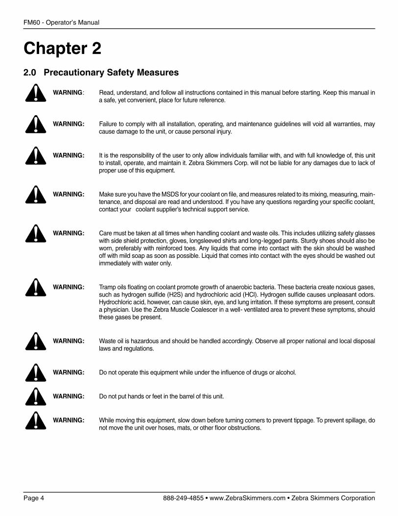
WARNING: Read, understand, and follow all instructions contained in this manual before starting. Keep this manual in a safe, yet convenient, place for future reference.
WARNING: Failure to comply with all installation, operating, and maintenance guidelines will void all warranties, may cause damage to the unit, or cause personal injury.
WARNING: It is the responsibility of the user to only allow individuals familiar with, and with full knowledge of, this unit to install, operate, and maintain it. Zebra Skimmers Corp. will not be liable for any damages due to lack of proper use of this equipment.
WARNING: Make sure you have the MSDS for your coolant on file, and measures related to its mixing, measuring, main-tenance, and disposal are read and understood. If you have any questions regarding your specific coolant, contact your coolant supplier’s technical support service.
WARNING: Care must be taken at all times when handling coolant and waste oils. This includes utilizing safety glasses with side shield protection, gloves, longsleeved shirts and long-legged pants. Sturdy shoes should also be worn, preferably with reinforced toes. Any liquids that come into contact with the skin should be washed off with mild soap as soon as possible. Liquid that comes into contact with the eyes should be washed out immediately with water only.
WARNING: Tramp oils floating on coolant promote growth of anaerobic bacteria. These bacteria create noxious gases, such as hydrogen sulfide (H2S) and hydrochloric acid (HCl). Hydrogen sulfide causes unpleasant odors. Hydrochloric acid, however, can cause skin, eye, and lung irritation. If these symptoms are present, consult a physician. Use the Zebra Muscle Coalescer in a well- ventilated area to prevent these symptoms, should these gases be present.
WARNING: Waste oil is hazardous and should be handled accordingly. Observe all proper national and local disposal laws and regulations.
WARNING: Do not operate this equipment while under the influence of drugs or alcohol.
WARNING: Do not put hands or feet in the barrel of this unit.
WARNING: While moving this equipment, slow down before turning corners to prevent tippage. To prevent spillage, do not move the unit over hoses, mats, or other floor obstructions.
FM60 - Operator’s Manual
Page 4 888-249-4855 • www.ZebraSkimmers.com • Zebra Skimmers Corporation
FM60 - Operator’s Manual
888-249-4855 • www.ZebraSkimmers.com • Zebra Skimmers Corporation Page 5
Chapter 33.0 Component Review
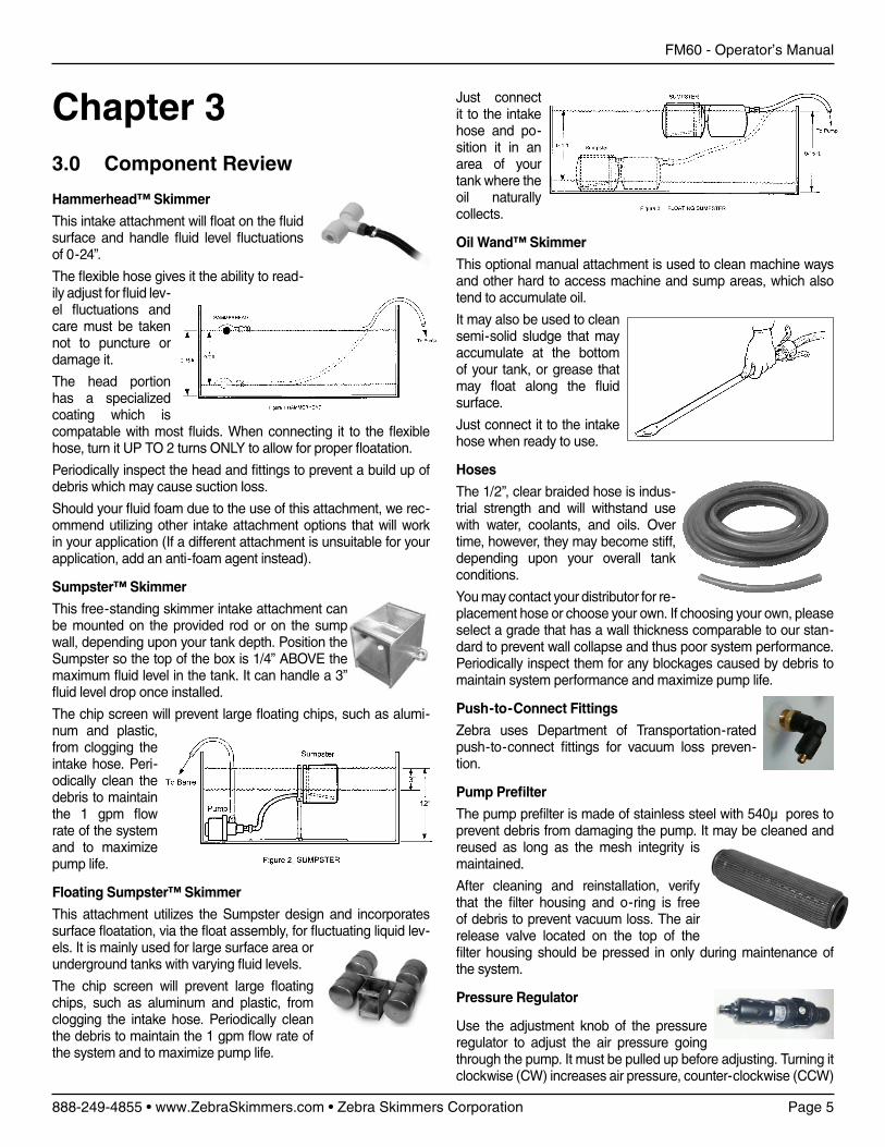
Hammerhead™ Skimmer
This intake attachment will float on the fluid surface and handle fluid level fluctuations of 0-24”.
The flexible hose gives it the ability to read-ily adjust for fluid lev-el fluctuations and care must be taken not to puncture or damage it.
The head portion has a specialized coating which is compatable with most fluids. When connecting it to the flexible hose, turn it UP TO 2 turns ONLY to allow for proper floatation.
Periodically inspect the head and fittings to prevent a build up of debris which may cause suction loss.
Should your fluid foam due to the use of this attachment, we rec-ommend utilizing other intake attachment options that will work in your application (If a different attachment is unsuitable for your application, add an anti-foam agent instead).
Sumpster™ Skimmer
This free-standing skimmer intake attachment can be mounted on the provided rod or on the sump wall, depending upon your tank depth. Position the Sumpster so the top of the box is 1/4” ABOVE the maximum fluid level in the tank. It can handle a 3” fluid level drop once installed.
The chip screen will prevent large floating chips, such as alumi-num and plastic, from clogging the intake hose. Peri-odically clean the debris to maintain the 1 gpm flow rate of the system and to maximize pump life.
Floating Sumpster™ Skimmer
This attachment utilizes the Sumpster design and incorporates surface floatation, via the float assembly, for fluctuating liquid lev-els. It is mainly used for large surface area or underground tanks with varying fluid levels.
The chip screen will prevent large floating chips, such as aluminum and plastic, from clogging the intake hose. Periodically clean the debris to maintain the 1 gpm flow rate of the system and to maximize pump life.
Just connect it to the intake hose and po-sition it in an area of your tank where the oil naturally collects.
Oil Wand™ Skimmer
This optional manual attachment is used to clean machine ways and other hard to access machine and sump areas, which also tend to accumulate oil.
It may also be used to clean semi-solid sludge that may accumulate at the bottom of your tank, or grease that may float along the fluid surface.
Just connect it to the intake hose when ready to use.
Hoses
The 1/2”, clear braided hose is indus-trial strength and will withstand use with water, coolants, and oils. Over time, however, they may become stiff, depending upon your overall tank conditions.
You may contact your distributor for re-placement hose or choose your own. If choosing your own, please select a grade that has a wall thickness comparable to our stan-dard to prevent wall collapse and thus poor system performance. Periodically inspect them for any blockages caused by debris to maintain system performance and maximize pump life.
Push-to-Connect Fittings
Zebra uses Department of Transportation-rated push-to-connect fittings for vacuum loss preven-tion.
Pump Prefilter
The pump prefilter is made of stainless steel with 540µ pores to prevent debris from damaging the pump. It may be cleaned and reused as long as the mesh integrity is maintained.
After cleaning and reinstallation, verify that the filter housing and o-ring is free of debris to prevent vacuum loss. The air release valve located on the top of the filter housing should be pressed in only during maintenance of the system.
Pressure Regulator
Use the adjustment knob of the pressure regulator to adjust the air pressure going through the pump. It must be pulled up before adjusting. Turning it clockwise (CW) increases air pressure, counter-clockwise (CCW)
FM60 - Operator’s Manual
Page 6 888-249-4855 • www.ZebraSkimmers.com • Zebra Skimmers Corporation
FM60 - Operator’s Manual
888-249-4855 • www.ZebraSkimmers.com • Zebra Skimmers Corporation Page 7
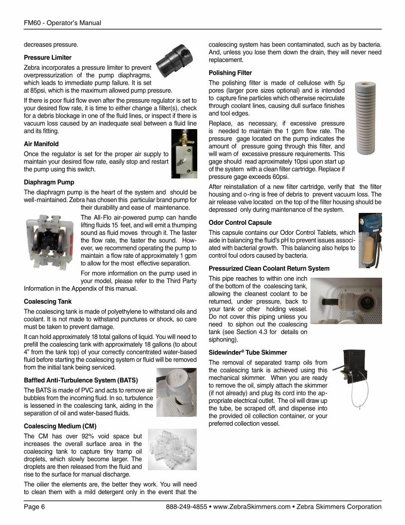
coalescing system has been contaminated, such as by bacteria. And, unless you lose them down the drain, they will never need replacement.
Polishing Filter
The polishing filter is made of cellulose with 5µ pores (larger pore sizes optional) and is intended to capture fine particles which otherwise recirculate through coolant lines, causing dull surface finishes and tool edges.
Replace, as necessary, if excessive pressure is needed to maintain the 1 gpm flow rate. The pressure gage located on the pump indicates the amount of pressure going through this filter, and will warn of excessive pressure requirements. This gage should read aproximately 10psi upon start up of the system with a clean filter cartridge. Replace if pressure gage exceeds 60psi.
After reinstallation of a new filter cartridge, verify that the filter housing and o-ring is free of debris to prevent vacuum loss. The air release valve located on the top of the filter housing should be depressed only during maintenance of the system.
Odor Control Capsule
This capsule contains our Odor Control Tablets, which aide in balancing the fluid’s pH to prevent issues associ-ated with bacterial growth. This balancing also helps to control foul odors caused by bacteria.
Pressurized Clean Coolant Return System
This pipe reaches to within one inch of the bottom of the coalescing tank, allowing the cleanest coolant to be returned, under pressure, back to your tank or other holding vessel. Do not cover this piping unless you need to siphon out the coalescing tank (see Section 4.3 for details on siphoning).
Sidewinder® Tube Skimmer
The removal of separated tramp oils from the coalescing tank is achieved using this mechanical skimmer. When you are ready to remove the oil, simply attach the skimmer (if not already) and plug its cord into the ap-propriate electrical outlet. The oil will draw up the tube, be scraped off, and dispense into the provided oil collection container, or your preferred collection vessel.
decreases pressure.
Pressure Limiter
Zebra incorporates a pressure limiter to prevent overpressurization of the pump diaphragms, which leads to immediate pump failure. It is set at 85psi, which is the maximum allowed pump pressure.
If there is poor fluid flow even after the pressure regulator is set to your desired flow rate, it is time to either change a filter(s), check for a debris blockage in one of the fluid lines, or inspect if there is vacuum loss caused by an inadequate seal between a fluid line and its fitting.
Air Manifold
Once the regulator is set for the proper air supply to maintain your desired flow rate, easily stop and restart the pump using this switch.
Diaphragm Pump
The diaphragm pump is the heart of the system and should be well-maintained. Zebra has chosen this particular brand pump for
their durability and ease of maintenance.
The All-Flo air-powered pump can handle lifting fluids 15 feet, and will emit a thumping sound as fluid moves through it. The faster the flow rate, the faster the sound. How-ever, we recommend operating the pump to maintain a flow rate of approximately 1 gpm to allow for the most effective separation.
For more information on the pump used in your model, please refer to the Third Party
Information in the Appendix of this manual.
Coalescing Tank
The coalescing tank is made of polyethylene to withstand oils and coolant. It is not made to withstand punctures or shock, so care must be taken to prevent damage.
It can hold approximately 18 total gallons of liquid. You will need to prefill the coalescing tank with approximately 18 gallons (to about 4” from the tank top) of your correctly concentrated water-based fluid before starting the coalescing system or fluid will be removed from the initial tank being serviced.
Baffled Anti-Turbulence System (BATS)
The BATS is made of PVC and acts to remove air bubbles from the incoming fluid. In so, turbulence is lessened in the coalescing tank, aiding in the separation of oil and water-based fluids.
Coalescing Medium (CM)
The CM has over 92% void space but increases the overall surface area in the coalescing tank to capture tiny tramp oil droplets, which slowly become larger. The droplets are then released from the fluid and rise to the surface for manual discharge.
The oilier the elements are, the better they work. You will need to clean them with a mild detergent only in the event that the
FM60 - Operator’s Manual
Page 6 888-249-4855 • www.ZebraSkimmers.com • Zebra Skimmers Corporation
FM60 - Operator’s Manual
888-249-4855 • www.ZebraSkimmers.com • Zebra Skimmers Corporation Page 7
��� ����������������
���� ��������������
���������������
�������������
������� ����
��� ����
����
������������������
��������
���������
����������������
��������������
�������
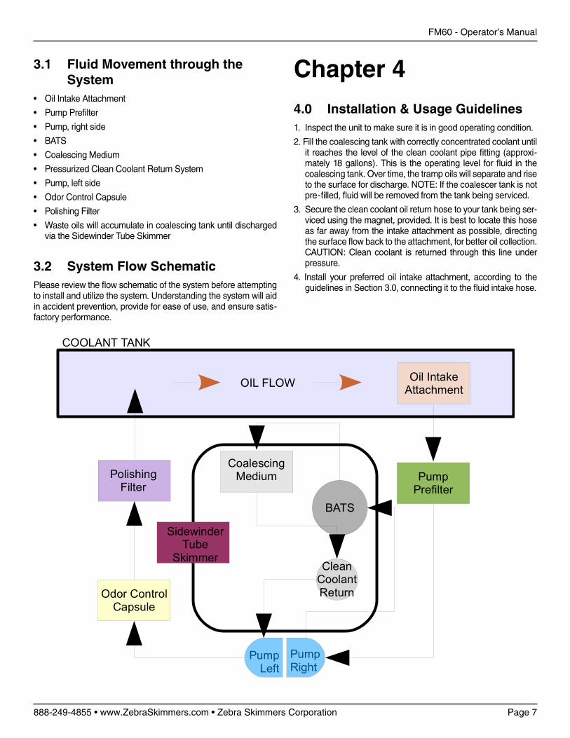
3.1 Fluid Movement through the System
• Oil Intake Attachment
• Pump Prefilter
• Pump, right side
• BATS
• Coalescing Medium
• Pressurized Clean Coolant Return System
• Pump, left side
• Odor Control Capsule
• Polishing Filter
• Waste oils will accumulate in coalescing tank until discharged via the Sidewinder Tube Skimmer
3.2 System Flow SchematicPlease review the flow schematic of the system before attempting to install and utilize the system. Understanding the system will aid in accident prevention, provide for ease of use, and ensure satis-factory performance.
Chapter 4
4.0 Installation & Usage Guidelines1. Inspect the unit to make sure it is in good operating condition.
2. Fill the coalescing tank with correctly concentrated coolant until it reaches the level of the clean coolant pipe fitting (approxi-mately 18 gallons). This is the operating level for fluid in the coalescing tank. Over time, the tramp oils will separate and rise to the surface for discharge. NOTE: If the coalescer tank is not pre-filled, fluid will be removed from the tank being serviced.
3. Secure the clean coolant oil return hose to your tank being ser-viced using the magnet, provided. It is best to locate this hose as far away from the intake attachment as possible, directing the surface flow back to the attachment, for better oil collection. CAUTION: Clean coolant is returned through this line under pressure.
4. Install your preferred oil intake attachment, according to the guidelines in Section 3.0, connecting it to the fluid intake hose.
FM60 - Operator’s Manual
Page 8 888-249-4855 • www.ZebraSkimmers.com • Zebra Skimmers Corporation
FM60 - Operator’s Manual
888-249-4855 • www.ZebraSkimmers.com • Zebra Skimmers Corporation Page 9
5. Connect your air hose to the air connection fitting. Turn the air manifold to the ON position. Lift the regulator knob and adjust it to 10-20 psi to allow for a beginning flow rate of approximately 1-2 gpm. We recommend the flow rate of 1-2 gpm for the most effective separation. Running the system at a higher flow rate may only recirculate tramp oils back to the tank being serviced. NOTE: As the filters fills with debris, you may need to operate the pump at a higher pressure. It is best to clean the filters if you require more than 60 psi to maintain the flow rate. If the filters are clean and you still require more pressure, than check for an air leak or blockage in each component and its related fittings. Higher pressures may also be needed for below-ground ap-plications, in relation to the distance of lift required.
4.1 Oil Accumulation & Waste Discharge
Once the fluid is drawn into the coalescing tank, it will begin to separate into two main layers. The tramp oil will float to the top of the tank and waterbased fluids will accumulate toward the bottom of the coalescing tank. The degree of this separation will be strictly determined by these factors:
• The strength of the water-based fluids anti-emulsification com-ponents (as in metalworking fluid, aka coolants)
• The amount of base oils in the coolant blend
• The age and quality of the water-based fluid
• The age and quality of the tramp oils
• Chemical instabilities caused by other additives entering fluid pool
• The flow rate of the coalescing system
If there is not a complete separation of the oil and water portions, then a slower flow rate may be necessary, as your fluids have lost the ability to gravity separate within 10-20 minutes.
You may notice a third layer which does not completely separate at all. These are called inverse layers, and are generally caused by high pressure systems which further emulsify oils into one an-other. Consider this layer as waste and discharge it regularly.
The Oasis is not intended to separate a straight oil from another straight oil and/or tramp oils and will only filter particles that re-main in suspension long enough for the intake attachment to draw them in.
Discharge the waste oil portion to a waste container using the Sidewinder Tube Skimmer. We recommend maintaining a waste oil level of about 2-3” of tramp oil before discharge (the build up of a small amount of oil encourages better separation).
4.2 Finishing Up1. Once the oils have been removed from the tank being
skimmed, remove the oil intake attachment.
2. Shut the pump off by adjusting the regulator or switching the air manifold to the OFF position. NOTE: See Section 4.3 for details on emptying the tank, if necessary, before proceeding further.
3. Disconnect your air line from the air intake fitting.
4. Remove the return line by lifting it near its connection to the coalescing tank to free it of liquid.
5. Transport the coalescer to the next tank that needs to be skimmed of oil, and repeat Steps 3-6 in Section 4.0.
4.3 Emptying the Coalescing Tank1. Move the Oasis to a your preferred holding tank which will hold
at least 20 gallons of fluid.
2. Lower the discharge hose into your holding tank, securing it in position.
3. Place the 2” PVC cap, provided, on the pressurized clean cool-ant return system so there is an airtight seal. You may also use the palm of your hand (see Section 3.2).
NOTE: Some coolant left in the tank is normal. All of the fluid should evacuate, except for that portion below the clean coolant return pipe.
4.4 Storing the SystemIt is recommended to empty the coalescing tank before storing the system for more than one day. Holding liquid in the tank can contribute to bacterial contamination of the coalescer, and thus your equipment. We recommend utilizing an Oxygenator™ when storing fluids in the coalescing tank to minimize bacterial growth.
4.5 Cleaning the System1. Tilt filter housings in upward direction. Empty coalescing tank
and hoses of all fluids (refer to Section 4.3).
2. Discard the cellulose polishing filter.
3. Mix a 10% solution of a mild degreasing agent to clean the coalescing tank and stainless steel filter. A pressure washer works well, or just clean by hand.
4. Rinse thoroughly with straight water.
5. Dispose of wash and rinse baths in accordance to federal, state, and local environmental laws and regulations.
6. Replace filter(s), making sure o-ring is free of debris and seated correctly.
7. Double-check all hoses, fittings, and attachments for cracks and obstructions.
FM60 - Operator’s Manual
Page 8 888-249-4855 • www.ZebraSkimmers.com • Zebra Skimmers Corporation
FM60 - Operator’s Manual
888-249-4855 • www.ZebraSkimmers.com • Zebra Skimmers Corporation Page 9
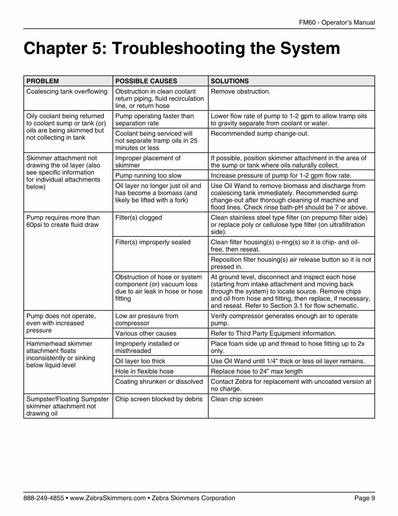
Chapter 5: Troubleshooting the System
PROBLEM POSSIBLE CAUSES SOLUTIONS
Coalescing tank overflowing Obstruction in clean coolant return piping, fluid recirculation line, or return hose
Remove obstruction.
Oily coolant being returned to coolant sump or tank (or) oils are being skimmed but not collecting in tank
Pump operating faster than separation rate
Lower flow rate of pump to 1-2 gpm to allow tramp oils to gravity separate from coolant or water.
Coolant being serviced will not separate tramp oils in 25 minutes or less
Recommended sump change-out.
Skimmer attachment not drawing the oil layer (also see specific information for individual attachments below)
Improper placement of skimmer
If possible, position skimmer attachment in the area of the sump or tank where oils naturally collect.
Pump running too slow Increase pressure of pump for 1-2 gpm flow rate.
Oil layer no longer just oil and has become a biomass (and likely be lifted with a fork)
Use Oil Wand to remove biomass and discharge from coalescing tank immediately. Recommended sump change-out after thorough cleaning of machine and flood lines. Check rinse bath-pH should be 7 or above.
Pump requires more than 60psi to create fluid draw
Filter(s) clogged Clean stainless steel type filter (on prepump filter side) or replace poly or cellulose type filter (on ultrafiltration side).
Filter(s) improperly sealed Clean filter housing(s) o-ring(s) so it is chip- and oil-free, then reseat.
Reposition filter housing(s) air release button so it is not pressed in.
Obstruction of hose or system component (or) vacuum loss due to air leak in hose or hose fitting
At ground level, disconnect and inspect each hose (starting from intake attachment and moving back through the system) to locate source. Remove chips and oil from hose and fitting, then replace, if necessary, and reseat. Refer to Section 3.1 for flow schematic.
Pump does not operate, even with increased pressure
Low air pressure from compressor
Verify compressor generates enough air to operate pump.
Various other causes Refer to Third Party Equipment information.
Hammerhead skimmer attachment floats inconsistently or sinking below liquid level
Improperly installed or misthreaded
Place foam side up and thread to hose fitting up to 2x only.
Oil layer too thick Use Oil Wand until 1/4” thick or less oil layer remains.
Hole in flexible hose Replace hose to 24” max length
Coating shrunken or dissolved Contact Zebra for replacement with uncoated version at no charge.
Sumpster/Floating Sumpster skimmer attachment not drawing oil
Chip screen blocked by debris Clean chip screen
FM60 - Operator’s Manual
Page 10 888-249-4855 • www.ZebraSkimmers.com • Zebra Skimmers Corporation
FM60 - Operator’s Manual
888-249-4855 • www.ZebraSkimmers.com • Zebra Skimmers Corporation Page 11
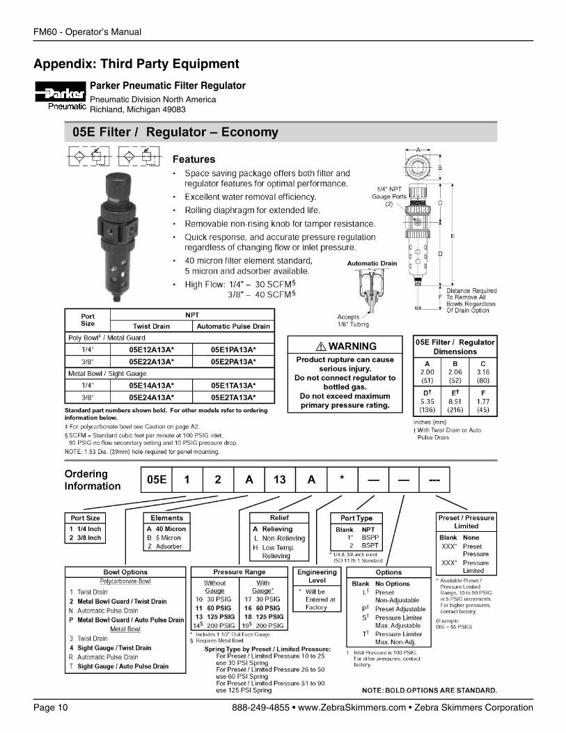
Appendix: Third Party Equipment
Parker Pneumatic Filter RegulatorPneumatic Division North AmericaRichland, Michigan 49083
FM60 - Operator’s Manual
Page 10 888-249-4855 • www.ZebraSkimmers.com • Zebra Skimmers Corporation
FM60 - Operator’s Manual
888-249-4855 • www.ZebraSkimmers.com • Zebra Skimmers Corporation Page 11
FM60 - Operator’s Manual
Page 12 888-249-4855 • www.ZebraSkimmers.com • Zebra Skimmers Corporation
FM60 - Operator’s Manual
888-249-4855 • www.ZebraSkimmers.com • Zebra Skimmers Corporation Page 13
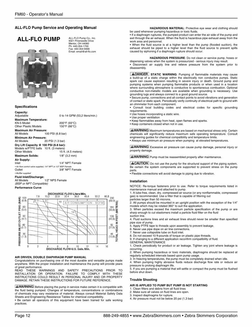
ALL-FLO Pump Service and Operating Manual
ALL-FLO PUMP ALL-FLO Pump Co., Inc.9321 Pineneedle DriveMentor, OH 44060Ph: 440-354-1700Fax: 440-354-9466Email: [email protected]
AIR DRIVEN, DOUBLE DIAPHRAGM PUMP MANUALCongratulations on purchasing one of the most durable and versatile pumps made anywhere. With the proper installation and maintenance the pump will provide years of great performance. READ THESE WARNINGS AND SAFETY PRECAUTIONS PRIOR TO INSTALLATION OR OPERATION. FAILURE TO COMPLY WITH THESE INSTRUCTIONS COULD RESULT IN PERSONAL INJURY AND OR PROPERTY DAMAGE. RETAIN THESE INSTRUCTIONS FOR FUTURE REFERENCE.
Before placing the pump in service make certain it is compatible with the fluid being pumped. Changes of temperature, concentrations or combinations of chemicals may vary resistance of material. Always consult Material Safety Data Sheets and Engineering Resistance Tables for chemical compatibility.• Be certain all operators of this equipment have been trained for safe working practices.
Specifications
Capacity:Adjustable 0 to 14 GPM (53,2 liters/min.)Maximum Temperature:KN-5 Model 200°F (93°C)Other Plastic Models 150°F (66°C)Maximum Air Pressure:All Models 100 PSI (6.8 bar)Minimum Air Pressure:All Models 20 PSI (1.3 bar)Dry Lift Capacity @ 100 PSI (6.8 bar):Models w/PTFE balls 10 ft. (3 meters)Other Models 15 ft. (4.5 meters)Masimum Solids: 1/8” (3.2 mm)Air Supply:Inlet 1/4” NPT Female• Air flow control valve supplied, 1/4” NPT or 1/2” BSP Female
Outlet 3/8” NPT Female• Muffler supplied
Fluid Inlet/Discharge:All Models 1/2” NPS Female(BSP or NPT Compatible)Performance Curve
HAZARDOUS MATERIAL: Protective eye wear and clothing should be used whenever pumping hazardous or toxic fluids.• If a diaphragm ruptures, the pumped product can enter the air side of the pump and exit through the air exhaust. When the fluid is hazardous pipe exhaust away from the work area and personnel.• When the fluid source is at a higher level than the pump (flooded suction), the exhaust should be piped to a higher level than the fluid source to prevent spills caused by siphoning if a diaphragm rupture should occur.
HAZARDOUS PRESSURE: Do not clean or service pump, hoses or dispensing valves when the system is pressurized - serious injury may result.• Disconnect air supply line and relieve pressure from the system prior to disassembly.
STATIC WARNING: Pumping of flammable materials may cause a build-up of a static charge within the electrically non conductive pumps. Static spark can cause explosion resulting in severe injury or death. Ground pump and pumping systems when pumping flammable products or when used in a location where surrounding atmosphere is conductive to spontaneous combustion. Optional conductive non-metallic models are available when grounding is necessary. Use grounding lugs and always connect to a good ground source.• Secure pump, connections and all contact points to avoid vibrations and generation of contact or static spark. Periodically verify continuity of electrical path to ground with an ohmmeter from each component.• Consult local building codes and electrical codes for specific grounding requirements.• Use hoses incorporating a static wire.• Use proper ventilation• Keep flammables away from heat, open flames and sparks.• Keep containers closed when not in use.
Maximum temperatures are based on mechanical stress only. Certain chemicals will significantly reduce maximum safe operating temperature. Consult engineering guides for chemical compatibility and temperature limits.• Always use minimum air pressure when pumping at elevated temperatures.
Excessive air pressure can cause pump damage, personal injury or property damage.
Pump must be reassembled properly after maintenance.
Do not use the pump for the structural support of the piping system. Be certain the system components are supported to prevent stress on the pump parts.• Flexible connections will avoid damage to piping due to vibration.
InstallationNOTICE: Re-torque fasteners prior to use. Refer to torque requirements listed in maintenance manual and attached to pump.1. A lube-free, clean, dry, compressed air source (or any nonflammable, compressed gas) is recommended. Use a filter that is capable of filtering outparticles larger than 50 microns.2. All pumps should be mounted in an upright position with the exception of the 1/4” models which may be rotated 360° to suit the application.3. When particles exceed the maximum particle specification of the pump or are sharp enough to cut elastomers install a particle fluid filter on the fluidsuction line.4. Fluid suctions lines and air exhaust lines should never be smaller than specified pipe size of pump.5. Apply PTFE tape to threads upon assembly to prevent leakage.6. Never use pipe dope on air line connections.7. Never use collapsible tube on fluid inlet.8. Do not exceed 10 ft-pounds of torque on plastic pipe threads.9. If changing to a different application reconfirm compatibility of fluid.GENERAL MAINTENANCE1. Check periodically for product or air leakage. Tighten any joint where leakage is occurring.2. When pumping hazardous or toxic materials, diaphragms should be replaced at regularly scheduled intervals based upon pump usage.3. In freezing temperatures, the pump must be completely drained when idle.4. When pumping highly abrasive fluids reduce discharge flow rate or reduce air pressure to prolong diaphragm life.5. If you are pumping a material that will settle or compact the pump must be flushed before shut down.
Trouble Shooting
AIR IS APPLIED TO PUMP BUT PUMP IS NOT STARTING1. Clean filters and debris from all fluid lines2. Make sure all valves on fluid lines are open.3. Inspect diaphragms for rupture.4. Air pressure must not be below 20 psi (1,3 bar)
FM60 - Operator’s Manual
Page 12 888-249-4855 • www.ZebraSkimmers.com • Zebra Skimmers Corporation
FM60 - Operator’s Manual
888-249-4855 • www.ZebraSkimmers.com • Zebra Skimmers Corporation Page 13
PUMP IS PUMPING BUT NOT PRIMING1. Check all suction line connections for leakage.2. Inspect check valves for wear or debris.3. Suction lift specifications may be exceeded.4. If fluid is viscous use larger suction lines.LEAKAGE1. Retorque all fasteners to specified torque requirements.2. Replace o-rings.3. Inspect diaphragms for ruptureLOW FLOW RATE1. Confirm air pressure and air capacity at the air valve as required.2. Check for leaks in suction line or obstructions in lines.3. If fluid is viscous use larger suction lines.4. Viscosity of fluid may have increased if temperature is lower.AIR IN DISCHARGE LINES1. Check for leaks in suction lines.2. Inspect diaphragms for rupture.ERRATIC CYCLING1. Inspect check valve seats for debris.2. Inspect fluid lines for debris.3. Automatic valves must be properly functioning.4. Viscosity of product may be changing.PREMATURE DESTRUCTION OF WETTED COMPONENTS1. If fluid is abrasive slow down pump or increase size of pump2. Filter fluid for sharp objects.3. Make sure fluid is compatible with wetted materials.
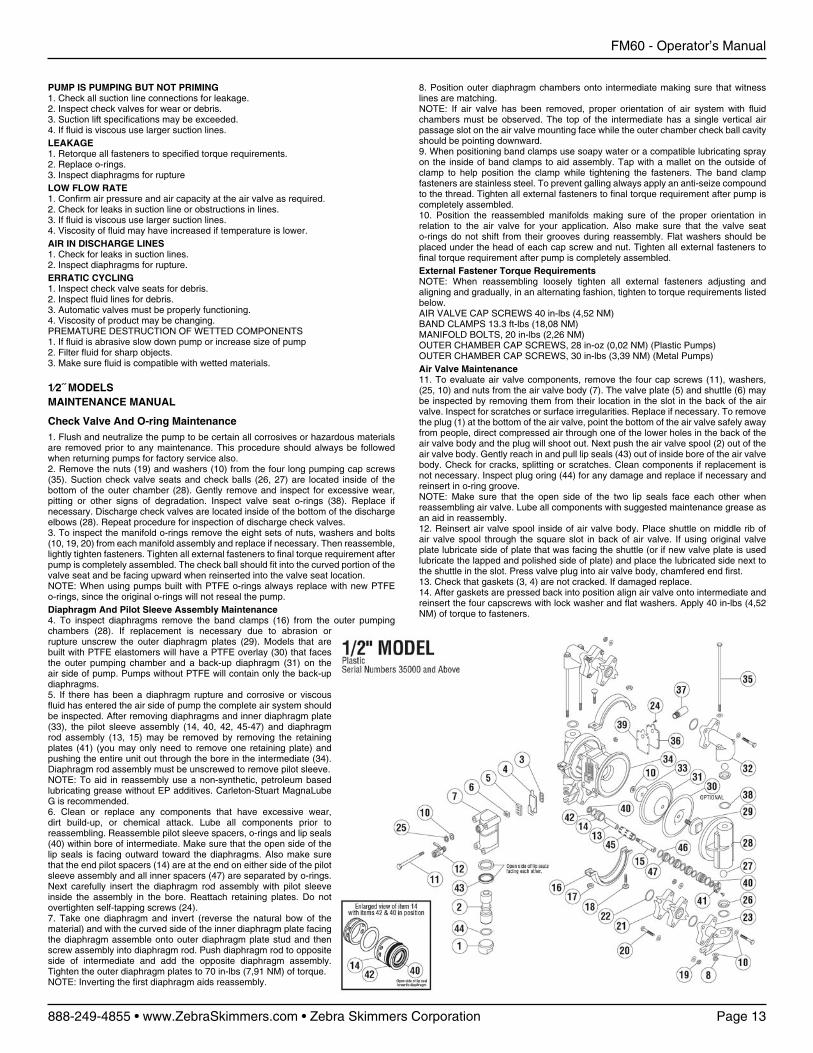
1⁄2˝ MODELSMAINTENANCE MANUAL
Check Valve And O-ring Maintenance1. Flush and neutralize the pump to be certain all corrosives or hazardous materials are removed prior to any maintenance. This procedure should always be followed when returning pumps for factory service also.2. Remove the nuts (19) and washers (10) from the four long pumping cap screws (35). Suction check valve seats and check balls (26, 27) are located inside of the bottom of the outer chamber (28). Gently remove and inspect for excessive wear, pitting or other signs of degradation. Inspect valve seat o-rings (38). Replace if necessary. Discharge check valves are located inside of the bottom of the discharge elbows (28). Repeat procedure for inspection of discharge check valves.3. To inspect the manifold o-rings remove the eight sets of nuts, washers and bolts (10, 19, 20) from each manifold assembly and replace if necessary. Then reassemble, lightly tighten fasteners. Tighten all external fasteners to final torque requirement after pump is completely assembled. The check ball should fit into the curved portion of the valve seat and be facing upward when reinserted into the valve seat location.NOTE: When using pumps built with PTFE o-rings always replace with new PTFE o-rings, since the original o-rings will not reseal the pump.Diaphragm And Pilot Sleeve Assembly Maintenance4. To inspect diaphragms remove the band clamps (16) from the outer pumping chambers (28). If replacement is necessary due to abrasion or rupture unscrew the outer diaphragm plates (29). Models that are built with PTFE elastomers will have a PTFE overlay (30) that faces the outer pumping chamber and a back-up diaphragm (31) on the air side of pump. Pumps without PTFE will contain only the back-up diaphragms.5. If there has been a diaphragm rupture and corrosive or viscous fluid has entered the air side of pump the complete air system should be inspected. After removing diaphragms and inner diaphragm plate (33), the pilot sleeve assembly (14, 40, 42, 45-47) and diaphragm rod assembly (13, 15) may be removed by removing the retaining plates (41) (you may only need to remove one retaining plate) and pushing the entire unit out through the bore in the intermediate (34). Diaphragm rod assembly must be unscrewed to remove pilot sleeve.NOTE: To aid in reassembly use a non-synthetic, petroleum based lubricating grease without EP additives. Carleton-Stuart MagnaLube G is recommended.6. Clean or replace any components that have excessive wear, dirt build-up, or chemical attack. Lube all components prior to reassembling. Reassemble pilot sleeve spacers, o-rings and lip seals (40) within bore of intermediate. Make sure that the open side of the lip seals is facing outward toward the diaphragms. Also make sure that the end pilot spacers (14) are at the end on either side of the pilot sleeve assembly and all inner spacers (47) are separated by o-rings. Next carefully insert the diaphragm rod assembly with pilot sleeve inside the assembly in the bore. Reattach retaining plates. Do not overtighten self-tapping screws (24).7. Take one diaphragm and invert (reverse the natural bow of the material) and with the curved side of the inner diaphragm plate facing the diaphragm assemble onto outer diaphragm plate stud and then screw assembly into diaphragm rod. Push diaphragm rod to opposite side of intermediate and add the opposite diaphragm assembly. Tighten the outer diaphragm plates to 70 in-lbs (7,91 NM) of torque.NOTE: Inverting the first diaphragm aids reassembly.
8. Position outer diaphragm chambers onto intermediate making sure that witness lines are matching.NOTE: If air valve has been removed, proper orientation of air system with fluid chambers must be observed. The top of the intermediate has a single vertical air passage slot on the air valve mounting face while the outer chamber check ball cavity should be pointing downward.9. When positioning band clamps use soapy water or a compatible lubricating spray on the inside of band clamps to aid assembly. Tap with a mallet on the outside of clamp to help position the clamp while tightening the fasteners. The band clamp fasteners are stainless steel. To prevent galling always apply an anti-seize compound to the thread. Tighten all external fasteners to final torque requirement after pump is completely assembled.10. Position the reassembled manifolds making sure of the proper orientation in relation to the air valve for your application. Also make sure that the valve seat o-rings do not shift from their grooves during reassembly. Flat washers should be placed under the head of each cap screw and nut. Tighten all external fasteners to final torque requirement after pump is completely assembled.External Fastener Torque RequirementsNOTE: When reassembling loosely tighten all external fasteners adjusting and aligning and gradually, in an alternating fashion, tighten to torque requirements listed below.AIR VALVE CAP SCREWS 40 in-lbs (4,52 NM)BAND CLAMPS 13.3 ft-lbs (18,08 NM)MANIFOLD BOLTS, 20 in-lbs (2,26 NM)OUTER CHAMBER CAP SCREWS, 28 in-oz (0,02 NM) (Plastic Pumps)OUTER CHAMBER CAP SCREWS, 30 in-lbs (3,39 NM) (Metal Pumps)Air Valve Maintenance11. To evaluate air valve components, remove the four cap screws (11), washers, (25, 10) and nuts from the air valve body (7). The valve plate (5) and shuttle (6) may be inspected by removing them from their location in the slot in the back of the air valve. Inspect for scratches or surface irregularities. Replace if necessary. To remove the plug (1) at the bottom of the air valve, point the bottom of the air valve safely away from people, direct compressed air through one of the lower holes in the back of the air valve body and the plug will shoot out. Next push the air valve spool (2) out of the air valve body. Gently reach in and pull lip seals (43) out of inside bore of the air valve body. Check for cracks, splitting or scratches. Clean components if replacement is not necessary. Inspect plug oring (44) for any damage and replace if necessary and reinsert in o-ring groove.NOTE: Make sure that the open side of the two lip seals face each other when reassembling air valve. Lube all components with suggested maintenance grease as an aid in reassembly.12. Reinsert air valve spool inside of air valve body. Place shuttle on middle rib of air valve spool through the square slot in back of air valve. If using original valve plate lubricate side of plate that was facing the shuttle (or if new valve plate is used lubricate the lapped and polished side of plate) and place the lubricated side next to the shuttle in the slot. Press valve plug into air valve body, chamfered end first.13. Check that gaskets (3, 4) are not cracked. If damaged replace.14. After gaskets are pressed back into position align air valve onto intermediate and reinsert the four capscrews with lock washer and flat washers. Apply 40 in-lbs (4,52 NM) of torque to fasteners.
FM60 - Operator’s Manual
Page 14 888-249-4855 • www.ZebraSkimmers.com • Zebra Skimmers Corporation
FM60 - Operator’s Manual
888-249-4855 • www.ZebraSkimmers.com • Zebra Skimmers Corporation Page 15
Without P
roperM
aintenance
With
Proper
Maintenance
ABC
D
E
F
G
Co
ola
nt
Per
form
ance
Lev
el (
see
no
te)
Time 1 m0. 2 m0. 4 m0. 8 m0. 1 yr. 1.25 yr. 1.5 yr. 1.75 yr. 2 yr.
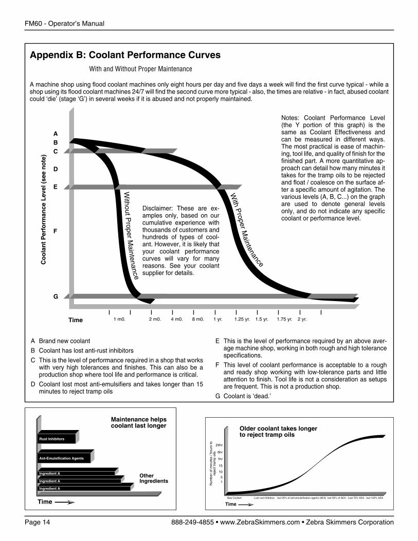
Appendix B: Coolant Performance Curves With and Without Proper Maintenance
A machine shop using flood coolant machines only eight hours per day and five days a week will find the first curve typical - while a shop using its flood coolant machines 24/7 will find the second curve more typical - also, the times are relative - in fact, abused coolant could ‘die’ (stage ‘G’) in several weeks if it is abused and not properly maintained.
Disclaimer: These are ex-amples only, based on our cumulative experience with thousands of customers and hundreds of types of cool-ant. However, it is likely that your coolant performance curves will vary for many reasons. See your coolant supplier for details.
A Brand new coolant
B Coolant has lost anti-rust inhibitors
C This is the level of performance required in a shop that works with very high tolerances and finishes. This can also be a production shop where tool life and performance is critical.
D Coolant lost most anti-emulsifiers and takes longer than 15 minutes to reject tramp oils
Maintenance helpscoolant last longer
Time
Rust Inhibitors
Ant-Emulsification Agents
OtherIngredients
Ingredient A
Ingredient A
Ingredient A
Older coolant takes longerto reject tramp oils
Time
24hr
6hr
1hr
15
10
51
New Coolant Lost rust inhibitors lost 25% of anti-emulsification agents (AEA) lost 50% of AEA - Lost 75% AEA - lost 100% AEA
Num
ber
of m
inut
es /
hour
s to
reje
ct tr
amp
oils
E This is the level of performance required by an above aver-age machine shop, working in both rough and high tolerance specifications.
F This level of coolant performance is acceptable to a rough and ready shop working with low-tolerance parts and little attention to finish. Tool life is not a consideration as setups are frequent. This is not a production shop.
G Coolant is ‘dead.’
Notes: Coolant Performance Level (the Y portion of this graph) is the same as Coolant Effectiveness and can be measured in different ways. The most practical is ease of machin-ing, tool life, and quality of finish for the finished part. A more quantitative ap-proach can detail how many minutes it takes for the tramp oils to be rejected and float / coalesce on the surface af-ter a specific amount of agitation. The various levels (A, B, C...) on the graph are used to denote general levels only, and do not indicate any specific coolant or performance level.

FM60 - Operator’s Manual
Page 14 888-249-4855 • www.ZebraSkimmers.com • Zebra Skimmers Corporation
FM60 - Operator’s Manual
888-249-4855 • www.ZebraSkimmers.com • Zebra Skimmers Corporation Page 15
NOTES
Copyright 2009 © ZSCZebra Skimmers Corp.PO Box 833Chagrin Falls, OH 44022888-249-4855www.ZebraSkimmers.comwww.CoolantMaintenance.com