Embed Size (px)
Citation preview

Fujitsu Microelectronics (Shanghai) Co., Ltd. Application Note
MCU-AN- 500083-E-10
F²MC-8FX FAMILY 8-BIT MICROELECTRONICS
MB95350L SERIES
EV BOARD MB2146 - 460 - E
SETUP GUIDE

MB2146-460-E Setup Guide Revision History
MCU-AN-500083-E-10 – Page 2
Revision History
Date Author Change of Records 2010-04-09 Jane Li V1.0, First draft
This manual contains 59 pages.

MB2146-460-E Setup Guide PREFACE
MCU-AN-500083-E-10 – Page 3
PREFACE
Thank you for purchasing the F2MC*1-8FX Family EV-Board: MB2146-460-E*2. This product is an EV-Board for F2MC-8FX MB95F350L Series MCU, which comes with MB2146-08-E (F2MC-8FX BGM Adapter)*3, MB2146-460-E (F2MC-8FX Family MB95F350L Series Evaluation Board)*2 and F2MC-8L/8FX Family SOFTUNE Professional Pack Evaluation Version*4. This manual explains how to use the EV-Board. Be sure to read this manual before using the product. About mass production/evaluation MCUs for this product, please consult with sales representatives or support representatives. *1: F2MC is the abbreviation of FUJITSU Flexible Microcontroller. *2: Hereinafter referred as “EV-Board” MB2146-460-E is the EV-Board for MB95F350L MCU;
*3: Hereinafter referred as “BGMA”. *4: Hereinafter referred as “SOFTUNE”.
� Handling and usage
Handling and usage of this product and notes regarding its safe use are described in the manuals for products bundled with the EV-Board. Follow the instructions in the manuals to use this product. Keep this manual at hand so that you can refer to it anytime during use of this product.
� Notice on this document
All information included in this document is current as of the date it is issued. The information is subject to change without any prior notice. Please confirm the latest relevant information with the sales representatives.

MB2146-460-E Setup Guide PREFACE
MCU-AN-500083-E-10 – Page 4
� Caution of the products described in this document
The following precautions will apply to the product described in this manual. Indicate a potentially hazardous situation which, if not avoided appropriately, could result in death or serious injury and/or a fault in the user’s system.
Electric shock, Damage
Before performing any operation described in this manual, turn off all the power supplied to the system. Performing such an operation with the power on may cause an electric shock or device fault.
Electric shock, Damage
Once the product has been turned on, do not touch any metal part of it. Doing so may cause an electric shock or device fault.
Indicates the presence of a hazard that may cause a minor or moderate injury, damages to this product or devices connected to it, or may cause to lose software resources and other properties such as data, if the device is not used appropriately.
Cuts, Damage Before moving the product, be sure to turn off all the power supplies and unplug the cables. Watch your step when carrying the product. Do not use the product in an unstable location such as a place exposed to strong vibration or a sloping surface. Doing so may cause the product to fall, resulting in an injury or fault.
Cuts The product contains sharp edges that are left unavoidably exposed, such as jumper plugs. Handle the product with due care not to get injured with such pointed parts.
Damage Do not place anything on the product or expose the product to physical shocks. Do not carry the product after the power has been turned on. Doing so may cause a malfunction due to overloading or shock.
Damage
Since the product contains many electronic components, keep it away from directsunlight, high temperature, and high humidity to prevent condensation. Do not useor store the product where it is exposed to much dust or a strong magnetic or electric field for an extended period of time. Inappropriate operating or storage environments may cause a fault.
Damage Use the product within the ranges given in the specifications. Operation over the specified ranges may cause a fault.
Damage To prevent electrostatic breakdown, do not let your finger or other object come into contact with the metal parts of any of the connectors. Before handling the product, touch a metal object (such as a door knob) to discharge any static electricity from your body.
Damage Before turning the power on, in particular, be sure to finish making all the required connections. Furthermore, be sure to configure and use the product by following the instructions given in this document. Using the product incorrectly or inappropriately may cause a fault.
Damage Always turn the power off before connecting or disconnecting any cables from the product. When unplugging a cable, unplug the cable by holding the connector part without pulling on the cable itself. Pulling the cable itself or bending it may expose or disconnect the cable core, resulting in a fault.
Damage Because the structure of the MCU socket does not allow an evaluation MCU to be mounted in the incorrect orientation, be very careful of the orientation of the evaluation MCU when mounting it. Inserting the evaluation MCU in the wrong orientation may damage the MCU, causing the MCU to become faulty.
Damage Because the product has no casing, it is recommended that it be stored in the original packaging. Transporting the product may cause a damage or fault. Therefore, keep the packaging materials and use them in case of for the re-shipment of the product.
WARNING
CAUTION

MB2146-460-E Setup Guide PREFACE
MCU-AN-500083-E-10 – Page 5
© 2009 FUJITSU Microelectronics LIMITED
� The contents of this document are subject to change without notice. Customers are advised to consult with sales representatives before ordering.
� The information, such as descriptions of function and application circuit examples, in this document are presented solely for the purpose of reference to show examples of operations and uses of FUJITSU Microelectronics device; FUJITSU Microelectronics does not warrant proper operation of the device with respect to use based on such information. When you develop equipment incorporating the device based on such information, you must assume any responsibility arising out of such use of the information. FUJITSU Microelectronics assumes no liability for any damages whatsoever arising out of the use of the information.
� Any information in this document, including descriptions of function and schematic diagrams, shall not be construed as license of the use or exercise of any intellectual property right, such as patent right or copyright, or any other right of FUJITSU Microelectronics or any third party or does FUJITSU Microelectronics warrant non-infringement of any third-party's intellectual property right or other right by using such information. FUJITSU Microelectronics assumes no liability for any infringement of the intellectual property rights or other rights of third parties which would result from the use of information contained herein.
� The products described in this document are designed, developed and manufactured as contemplated for general use, including without limitation, ordinary industrial use, general office use, personal use, and household use, but are not designed, developed and manufactured as contemplated (1) for use accompanying fatal risks or dangers that, unless extremely high safety is secured, could have a serious effect to the public, and could lead directly to death, personal injury, severe physical damage or other loss (i.e., nuclear reaction control in nuclear facility, aircraft flight control, air traffic control, mass transport control, medical life support system, missile launch control in weapon system), or (2) for use requiring extremely high reliability (i.e., submersible repeater and artificial satellite). Please note that FUJITSU Microelectronics will not be liable against you and/or any third party for any claims or damages arising in connection with above-mentioned uses of the products.
� Any semiconductor devices have an inherent chance of failure. You must protect against injury, damage or loss from such failures by incorporating safety design measures into your facility and equipment such as redundancy, fire protection, and prevention of over-current levels and other abnormal operating conditions.
� Exportation/release of any products described in this document may require necessary procedures in accordance with the regulations of the Foreign Exchange and Foreign Trade Control Law of Japan and/or US export control laws.
� The company names and brand names herein are the trademarks or registered trademarks of their respective owners.

MB2146-460-E Setup Guide Contents
MCU-AN-500083-E-10 – Page 6
Contents
REVISION HISTORY ............................................................................................................ 2�
PREFACE ............................................................................................................................. 3��
Handling and usage ..................................................................................................... 3��
Notice on this document ............................................................................................... 3��
Caution of the products described in this document ..................................................... 4�
CONTENTS .......................................................................................................................... 6�
1� PRODUCT OVERVIEW ................................................................................................. 9�
1.1� Objective and Deliverable ........................................................................................ 9�
1.2� System Block .......................................................................................................... 9�
1.3� Handling Precautions .............................................................................................. 9�
1.4� Feature .................................................................................................................. 10�
1.5� Hardware Setup .................................................................................................... 10�
2� BGMA MANUAL .......................................................................................................... 11�
2.1� BGMA Overview .................................................................................................... 11�
2.2� Function List .......................................................................................................... 11�
2.3� IDC10 Interface Description .................................................................................. 12�
2.4� BGMA USB Configuration ..................................................................................... 12�
2.5� LED Description .................................................................................................... 15�
3� EV-BOARD MANUAL .................................................................................................. 16�
3.1� EV-board Overview ............................................................................................... 16�
3.2� Function List .......................................................................................................... 17�
3.3� EV-board Schematic ............................................................................................. 18�
3.4� HW Module Description and Jumper settings ........................................................ 19�
3.4.1� Pin Assignment of MB95350L .................................................................. 19�
3.4.2� Power Module .......................................................................................... 20�
3.4.3� I2C Slave Module .................................................................................... 21�
3.4.4� I2C master Module .................................................................................. 21�
3.4.5� A/D Module .............................................................................................. 22�
3.4.6� LED Module ............................................................................................. 23�
3.5� Operation Manual .................................................................................................. 24�
3.5.1� Single board mode ................................................................................... 24�
3.5.2� Series Connection Mode .......................................................................... 25�
3.5.3� Net Connection Mode .............................................................................. 26�
3.5.4� ADC module ............................................................................................ 27�
3.5.5� Wake-Up Operation ................................................................................. 27�

MB2146-460-E Setup Guide Contents
MCU-AN-500083-E-10 – Page 7
3.5.6� Reset Operation ...................................................................................... 28�
3.5.7� Test Pin ................................................................................................... 28�
3.5.8� Battery Usage .......................................................................................... 28�
4� SAMPLE CODE MANUAL ........................................................................................... 29�
4.1� Project Structure.................................................................................................... 29�
4.2� Source Code File Description ................................................................................ 30�
4.2.1� ADC .c ..................................................................................................... 30�
4.2.2� Addressjudge .c ....................................................................................... 31�
4.2.3� Ext-interrupt .c ......................................................................................... 32�
4.2.4� I2C .c ....................................................................................................... 33�
4.2.5� Initial .c .................................................................................................... 34�
4.2.6� Slavemodei2c .c ...................................................................................... 35�
4.2.7� Standby .c................................................................................................ 36�
4.2.8� Timer.c .................................................................................................... 37�
4.3� API Code File Description ..................................................................................... 39�
4.3.1� I2CMasterMacro.c ................................................................................... 39�
4.3.2� I2CSlaveMacro.c ..................................................................................... 41�
4.3.3� SleepMacro.c ........................................................................................... 42�
4.4� Global Variable Description ................................................................................... 43�
4.5� How to Add These Files ........................................................................................ 44�
4.6� Usage Demo ......................................................................................................... 45�
4.6.1� Code of main.c listed as following: ........................................................... 45�
4.6.2� Code of Initial_ADC listed as following: .................................................... 45�
4.6.3� Code of Read_ADC listed as following .................................................... 46�
4.6.4� Code of Judge_SlaveAddr listed as following .......................................... 46�
4.6.5� Code of Init_EXT listed as following ......................................................... 47�
4.6.6� Code of INTER_EXT listed as following ................................................... 47�
4.6.7� Code of I2C_Init listed as following .......................................................... 47�
4.6.8� Code of Read_I2C listed as following ...................................................... 48�
4.6.9� Code of Write_I2C listed as following ....................................................... 48�
4.6.10� Code of Initial listed as following .............................................................. 48�
4.6.11� Code of SlaveI2C_PrepareForInterlisted as following .............................. 49�
4.6.12� Code of INTER_I2CSlaveModeWakeUp as following .............................. 50�
4.6.13� Code of STBLED_ON as following .......................................................... 51�
4.6.14� Code of Write_StandBy as following ........................................................ 51�
4.6.15� Code of Clock_Init as following ................................................................ 51�
4.6.16� Code of TBT_Tim_Init as following .......................................................... 52�
4.6.17� Code of TBT_Init as following .................................................................. 52�

MB2146-460-E Setup Guide Contents
MCU-AN-500083-E-10 – Page 8
4.6.18� Code of TBT_Inter as following ................................................................ 53�
4.6.19� Code of Judge_P00 as following .............................................................. 54�
4.6.20� Code of LEDCoordin as following ............................................................ 54�
4.6.21� Code of EEPROM_I2C as following ......................................................... 55�
4.6.22� Code of EndDevice_I2C as following ....................................................... 55�
4.6.23� Code of I2C_MasterMacro as following ................................................... 56�
4.6.24� Code of I2C_SlaveMacro as following ..................................................... 56�
4.6.25� Code of Sleep_Macro as following ........................................................... 56�
5� DEVELOPMENT PLATFORM QUICK START ............................................................ 57�
5.1� Tools Setup Sequence .......................................................................................... 57�
5.2� Open Project and Start Debug ............................................................................... 57�
5.3� Operation Precautions ........................................................................................... 57�

MB2146-460-E Setup Guide Chapter 1 Product Overview
MCU-AN-500083-E-10 – Page 9
1 Product Overview
This product is a set of EV-Board of MB95350L series. It is composed of a BGMA (MB2146-08-E) and an EV-board (MB2146-460-E). Combining the SOFTUNE Workbench on PC, the EV-Board enables the quick start of development before the user system is ready.
1.1 Objective and Deliverable
The EV-Board provides users a complete development platform. Before starting using the EV-Board, please make sure that the following devices are placed in the package:
� EV-board (MB2146-460-E) 1PCS;
� Hardcopies (China RoHS Report, Quick Start Guide ) 2PCS
1.2 System Block
To set up a debugging system, first connect a PC, a BGMA and an EV-board together according to figure1.2-1.
Figure 1.2-1 System Block
1.3 Handling Precautions
The EV-Board can be used in connection with its bundled products. To use this product correctly in a proper environment, please observe the following guideline:
� Follow the instructions described in each manual for the bundled product to use this product.
BGMA
US
EV- Board �
Host PC
SOFTUNE
IDE
Sample code
Easy design and study MB95350L MCU with BGMA and SOFTUNE
MB95350L�MCU

MB2146-460-E Setup Guide Chapter 1 Product Overview
MCU-AN-500083-E-10 – Page 10
1.4 Feature
The MB95350L Series EV-Board is the best for a performance and functional evaluation, and operation check before using MB95350L Series MCU in a user's system.
The features of the BGM debugger for MB95350L Series MCU are shown as below.
� Microcomputer operation voltage ranging from +1.8V to +3.3V. � Compact development environment, a light and small BGM Adapter. � Since a monitor program is executed in a separate memory space, it does not consume
any user memory space. � Continuous execution, step execution and break correspondence. � It connects with a host computer by the USB interface.
1.5 Hardware Setup
In the hardware setup procedure, you should configure and connect the hardware products. This section introduces the configuring and connecting procedure for each product. Check the contents and complete the hardware setup.
� Configuration of each product - Configuring EV-Board
� Connection of each product - Connecting BGMA and EV-board
- Connecting EV-Board power supply

MB2146-460-E Setup Guide Chapter 2 BGMA Manual
MCU-AN-500083-E-10 – Page 11
2 BGMA Manual
This chapter gives introduction on how to set up BGMA.
2.1 BGMA Overview
Following is a close shot of a MB95350L Series BGMA. The Part Number is MB2146-08-E. It provides a debugging platform for the MB95350L Series MCU with a small size of 55.7mm (W) X127mm (D) X30mm (H).
Figure 2.1-1 BGMA Overview
2.2 Function List
ID Function description Remarks
1 Support MB95350L Series MCU MCU MAX machine clock: 16.25 MHz
MCU power supply voltage: 1.8*1*2 V ~ 3.3*1 V
2 Break pointer 256 software breakpoints
3 USB interface to PC/SOFTUNE Compatible to USB protocol version 1.1
4 1-Line UART interface to the MB95350L Series MCU The Baud rate is 62,500 bps.
5 Support the MCU flash programming for engineering development
The programming and reading speed is about 800 B/S.
*1: The value varies with the operating frequency, the machine clock or the analog guaranteed range.
*2: The value is 1.9V when the low-voltage detection resetting is used.
*3: The threshold voltage can be set as 1.9, 2.35 and 2.85V by software.
MB2146-460-E Setup Guide Chapter 2 BGMA Manual
MCU-AN-500083-E-10 – Page 12
2.3 IDC10 Interface Description
Pin Number Pin Name Description
1 UVCC Target MCU Vcc
2 GND Target MCU Vss
3 RSTIN Target MCU reset input
4 RSTOUT Target MCU reset output
5 RSV Reserved
6 RSV Reserved
7 RSV Reserved
8 DBG Target MCU debug pin
9 RSV Reserved
10 RSV Reserved
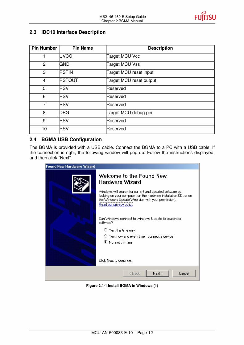
2.4 BGMA USB Configuration
The BGMA is provided with a USB cable. Connect the BGMA to a PC with a USB cable. If the connection is right, the following window will pop up. Follow the instructions displayed, and then click “Next”.
Figure 2.4-1 Install BGMA in Windows (1)

MB2146-460-E Setup Guide Chapter 2 BGMA Manual
MCU-AN-500083-E-10 – Page 13
Select “Install from a list or specific location (Advanced)”, then click “Next”,
Figure 2.4-2 Install BGMA in Windows (2)
Select “…\Drivers” from the folder where SOFTUNE is installed, click “Next”,
Figure 2.4-3 Install BGMA in Windows (3)

MB2146-460-E Setup Guide Chapter 2 BGMA Manual
MCU-AN-500083-E-10 – Page 14
Select “BGMA (MB2146-08)” from the window displayed in Figure 2.4-4, and then click “Next”,
Figure 2.4-4 Install BGMA in Windows (4)
Windows will install the driver automatically. Click “Finish” after the driver has completed the installation normally. Then users can find the BGMA is recognized as MB2146-08 in Windows system.
Figure 2.4-5 BGMA is installed in Windows

MB2146-460-E Setup Guide Chapter 2 BGMA Manual
MCU-AN-500083-E-10 – Page 15
2.5 LED Description
First, when USB cable is plugged to PC, check whether the Power LED turns green or not. Refer to Figure 2.5-1.
Figure 2.5-1 BGMA Power LED (1)
Second, plug IDC10 cable to the EV-board (target MCU board), then turn on EV-board. After that, check whether the Power LED on the BGMA turns orange or not. Refer to Figure 2.5-2.
Figure 2.5-2 BGMA Power LED (2)
�������
������� �����������������

MB2146-460-E Setup Guide Chapter 3 EV-board Manual
MCU-AN-500083-E-10 – Page 16
3 EV-board Manual
This chapter gives introduction on how to set up EV-board and functions of EV-Board.
3.1 EV-board Overview
MB95350L EV-board is an evaluation platform for the MB95350L Family microcontroller.
Figure 3.1-1 is a close shot of EV-board.
Figure 3.1-1 EV-board Overview
Power circuit BGMA
Circuit
LED circuit
Key circuit
ADC circuit I2C master circuit I2C slave circuit
MCU
Test pin

MB2146-460-E Setup Guide Chapter 3 EV-board Manual
MCU-AN-500083-E-10 – Page 17
3.2 Function List
The EV-board is consisted of a board and a sample firmware. The board, together with a BGMA (PN: MB2146-08-E) and a SOFTUNE, provides a useful platform for using the MCU and its peripherals. It features in the following functions.
� Support I2C, can write/read data to/from EEPROM or other chips
� Support I2C slave and I2C master
� Support A/D conversion
� Support standby mode and wake-up from I2C

MB2146-460-E Setup Guide Chapter 3 EV-board Manual
MCU-AN-500083-E-10 – Page 18
3.3 EV-board Schematic
Figure 3.3-1 EV-board Schematic
5
MB2146-460-E Setup Guide Chapter 3 EV-board Manual
MCU-AN-500083-E-10 – Page 19
3.4 HW Module Description and Jumper settings
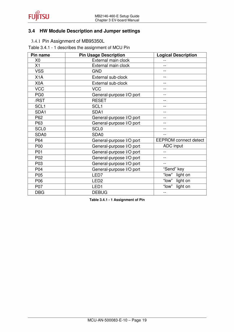
3.4.1 Pin Assignment of MB95350L Table 3.4.1 - 1 describes the assignment of MCU Pin
Pin name Pin Usage Description Logical Description X0 External main clock -- X1 External main clock -- VSS GND -- X1A External sub-clock -- X0A External sub-clock -- VCC VCC -- PG0 General-purpose I/O port -- /RST RESET -- SCL1 SCL1 -- SDA1 SDA1 -- P62 General-purpose I/O port -- P63 General-purpose I/O port -- SCL0 SCL0 -- SDA0 SDA0 -- P64 General-purpose I/O port EEPROM connect detect P00 General-purpose I/O port ADC input P01 General-purpose I/O port -- P02 General-purpose I/O port -- P03 General-purpose I/O port -- P04 General-purpose I/O port “Send” key P05 LED7 “low” light on P06 LED2 “low” light on P07 LED1 “low” light on DBG DEBUG --
Table 3.4.1 - 1 Assignment of Pin
MB2146-460-E Setup Guide Chapter 3 EV-board Manual
MCU-AN-500083-E-10 – Page 20
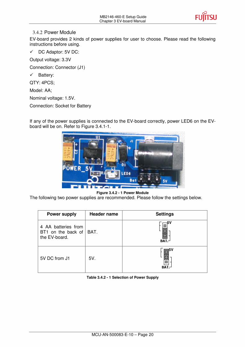
3.4.2 Power Module EV-board provides 2 kinds of power supplies for user to choose. Please read the following instructions before using.
� DC Adaptor: 5V DC:
Output voltage: 3.3V
Connection: Connector (J1)
� Battery:
QTY: 4PCS;
Model: AA;
Nominal voltage: 1.5V.
Connection: Socket for Battery
If any of the power supplies is connected to the EV-board correctly, power LED6 on the EV-board will be on. Refer to Figure 3.4.1-1.
Figure 3.4.2 - 1 Power Module
The following two power supplies are recommended. Please follow the settings below.
Power supply Header name Settings
4 AA batteries from BT1 on the back of the EV-board.
BAT.
5V DC from J1 5V.
Table 3.4.2 - 1 Selection of Power Supply
5V
5V

MB2146-460-E Setup Guide Chapter 3 EV-board Manual
MCU-AN-500083-E-10 – Page 21
3.4.3 I2C Slave Module The I2C slave is used to connect external master SDA and SCL. There are two channels in I2C slave module. The in channel is used for the board to receive slave information and the out channel transfers the same SDA and SCL information to another board.
3.4.4 I2C master Module There is a switcher near at24c04. When I2C is used to visit 24c04, the switcher should be set to the up side (IIC). When I2C is used to visit external chip, the switcher should be set to the down side (GND).
Figure 3.4.3 - 1 I2C Switch
Out channel In channel

MB2146-460-E Setup Guide Chapter 3 EV-board Manual
MCU-AN-500083-E-10 – Page 22
3.4.5 A/D Module Use A/D value to set address
Figure 3.4.4 - 1 ADC Module
Note: The orientation to which the section faced will decide the slave device
Orientation
1
Slave device1 Slave device2 Slave device3 Slave device4 Slave device5
2
3
4
5

MB2146-460-E Setup Guide Chapter 3 EV-board Manual
MCU-AN-500083-E-10 – Page 23
3.4.6 LED Module Three LEDs are connected to P07, P06 and P05, for showing the states
Table 3.4.5 - 1 LED Assignment
Sleep mode
Cooperate successful
Device selected

MB2146-460-E Setup Guide Chapter 3 EV-board Manual
MCU-AN-500083-E-10 – Page 24
3.5 Operation Manual
3.5.1 Single board mode
When you get one board, the board works singly as follows:
� When it is started (power on or reset), the IIC0 works as I2C master, and its sub-address is determined by the ADC.
� If “Send” key is pressed, the IIC0 will write the ADC data to at24c04, and then read from it.
� If the read data is same as the ADC data, LED2 will light on, or else it will be off.
� After that, system will enter sleep mode.
Note: The master jumper setting please refer to section 3.4.4

MB2146-460-E Setup Guide Chapter 3 EV-board Manual
MCU-AN-500083-E-10 – Page 25
3.5.2 Series Connection Mode
In series connection mode, main board and down board work as master and slave
simultaneously, while up board only works as master.
� After the ‘Send’ key on up board is pressed, the ADC value is sent to main board
� The Main board judges whether its address matches with the first data sent by up board.
� If the received address matches with the address of main board, the main board sends ACK to up board.
� Up board enters into sleep mode
� Main board saves the data received from up board.
� When the ‘Send’ key on main board is pressed, main board sends the saved data to down board
� Down board judges whether its address matches with the address sent by main board.
� If down board address match with its’ received address, down board sends ACK to main board
� Main board enters into sleep mode
� Down board saves the received data
� When the ‘Send’ key on down board is pressed, down board sends the saved data to EEPROM
� Down board enters into sleep mode
Note: for the master jumper setting please refer following:
Up board ---------- GND
Main board --------GND
Down board ------- IIC
Out In
Up board
Main board
Out In
Down board

MB2146-460-E Setup Guide Chapter 3 EV-board Manual
MCU-AN-500083-E-10 – Page 26
3.5.3 Net Connection Mode
In series connection mode, one board is the master board and the other boards are the
slave boards.
� Press “Send” key of master board, and the slave board whose potentiometer grade is same as that of master potentiometer will receive the data sent by master board.
� Turn the potentiometer to select different slave boards.
� Main board will enter into sleep after operation.
� After receiving data from master board, the slave board will save the data.
� When the ‘Send’ key on slave board is pressed, the saved data will be written and then read to/from its EEPROM.
� If the read data is same as the saved data, the LED (D2) will light on, or else the LED will be off.
� After operation, slave board will enter into sleep mode.
Note: for the master jumper setting please refer following:
Main board ---------- GND
Slave board1 --------IIC
Slave board2 -------- IIC
Out
In
In
Slave board1 Slave
board2
Main board
Potentiometer

MB2146-460-E Setup Guide Chapter 3 EV-board Manual
MCU-AN-500083-E-10 – Page 27
3.5.4 ADC module The potentiometer is divided into 5 grades, and each grade corresponds to one slave
board address. The slave address is divided into 0x10, 0x20, 0x30, 0x40 and 0x50. Details are as follow.
3.5.5 Wake-Up Operation After normal operation system will enter into sleep mode, and will be waked up by resetting, press “send” key, or I2C information.
� When system enter into sleep mode, the LED1 will light on
� After system wakes up, the LED1 will be off.

MB2146-460-E Setup Guide Chapter 3 EV-board Manual
MCU-AN-500083-E-10 – Page 28
3.5.6 Reset Operation There is a reset key to be used when user wants to reset system. In normal condition, the reset pin is connected to VCC. The reset key is connected to GND when being pressed.
3.5.7 Test Pin There is a test pin connected to each pin of MB95350L.
3.5.8 Battery Usage The supply power is 3.3V for MCU EEPROM and potentiometer. The EV-Board uses power chip AMS1117-3.3 to transfer input power from 5V to 3.3V. And the maximum number of battery supply is four cells (1.5V each cell). U2 is a switch to transfer between battery and power supply. For detail please refer to 3.4.2.
MB2146-460-E Setup Guide Chapter 4 Sample Code Manual
MCU-AN-500083-E-10 – Page 29
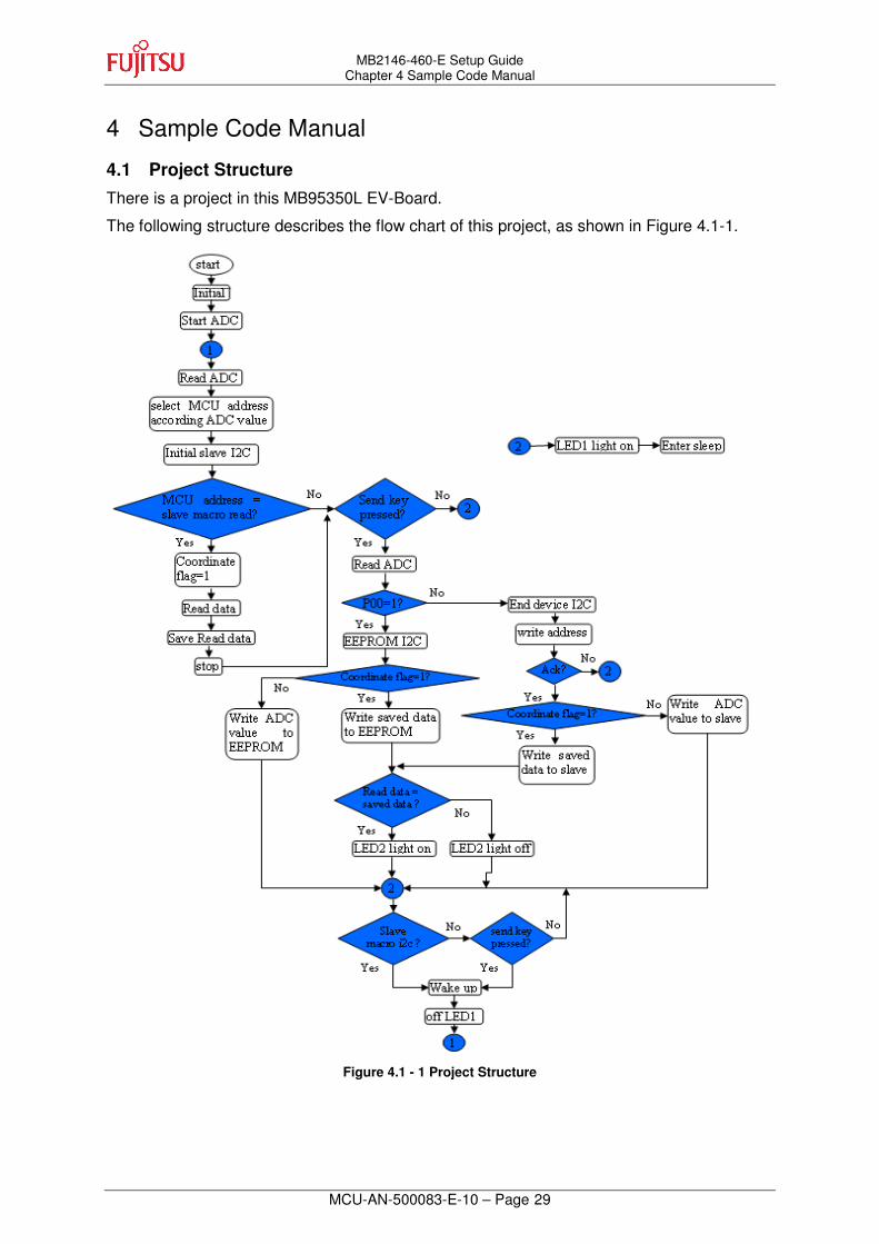
4 Sample Code Manual
4.1 Project Structure
There is a project in this MB95350L EV-Board.
The following structure describes the flow chart of this project, as shown in Figure 4.1-1.
Figure 4.1 - 1 Project Structure

MB2146-460-E Setup Guide Chapter 4 Sample Code Manual
MCU-AN-500083-E-10 – Page 30
The following sample codes are provided by MB95350L Series EV-Board,
4.2 Source Code File Description
Eight drive files are available in this project shown below,
Figure 4.2 - 1 Source Code Files
4.2.1 ADC .c Following table describes the ADC library:
Function Name Description
void ADC0_Init(void) Initialize ADC function
unsigned char Read_ADC(void) Read and return ADC value
Following table describes the function ADC0_Init.
Function name ADC0_Init
Function prototype void ADC0_Init(void)
Behavior description Initializes A/D module
Input parameter None
Return value None
Example Sets ADC input channel is AN00, and disable interrupt:
ADC0_Init();
Following table describes the function Read_ADC.
Function name Read_ADC
Function prototype unsigned char Read_ADC(void)
Behavior description Read the ADC result
Input parameter None
Return value Return ADC result
Example [variavle] = Read_ADC();

MB2146-460-E Setup Guide Chapter 4 Sample Code Manual
MCU-AN-500083-E-10 – Page 31
4.2.2 Addressjudge .c Following table describes the Addressjudge library:
Function Name Description
unsigned char Judge_SlaveAddr(unsigned char AddrJudg) Divide ADC value into five constants
When IIC0 is connected to multiple slave devices, these five constants are used decide which one to access.
Following table describes the function Addressjudge.
Function name Judge_SlaveAddr
Function prototype unsigned char Judge_SlaveAddr(unsigned char AddrJudg)
Behavior description Divide the ADC value to 5 areas: 0x10,0x20,0x30,0x40,0x50
Input parameter ADC value
Return value Area number
Example Judge ADC value 0x36 is belong to which area:
[variable] = Judge_SlaveAddr(0x36);

MB2146-460-E Setup Guide Chapter 4 Sample Code Manual
MCU-AN-500083-E-10 – Page 32
4.2.3 Ext-interrupt .c In this function, external interrupt registers are initialized.
Following table describes the external interrupt library:
Function Name Description
void EXT_Init(void) Initialize external interrupt
__interrupt void INTER_EXT (void) Capture falling edge and generate interrupt
Following table describes the function EXT_Init.
Function name EXT_Init
Function prototype void EXT_Init(void)
Behavior description Initialize external interrupt module
Input parameter None
Return value None
Example Set external channel to INT04, falling edge trigger and enable interrupt:
EXT_Init();
Following table describes the function INTER_EXT.
Function name INTER_EXT
Function prototype __interrupt void INTER_EXT(void)
Behavior description Indicate the send key pressed
Input parameter None
Return value None
Interrupt Level IRQ0: external interrupt ch0 | ch4
Example Be used in file vectors:
__interrupt void INTER_EXT(void);

MB2146-460-E Setup Guide Chapter 4 Sample Code Manual
MCU-AN-500083-E-10 – Page 33
4.2.4 I2C .c All following functions are for IIC0 which works as master.
Following table describes the I2C library:
Function Name Description
void I2C_Init( void ) Initialize I2C register
unsigned char Read_I2C(unsigned char DevAddr, unsigned char SubAddr) Read data for slave
void Write_I2C(unsigned char DevAddr, unsigned char SubAddr, unsigned char WDat) Write data to slave
Following table describes function I2C_Init.
Function name I2C_Init
Function prototype void I2C_Init( void )
Behavior description Initialize IIC0 module
Input parameter None
Return value None
Example Set I2C clock to 6.1khz,set I2C0 to master mode, disable interrupt:
I2C_Init ();
Following table describes function Read_I2C.
Function name Read_I2C
Function prototype unsigned char Read_I2C(unsigned char DevAddr, unsigned char SubAddr)
Behavior description Read data from slave device
Input parameter1 DevAddr: slave device address
Input parameter2 SubAddr: slave device sub-addres
Return value Data read from slave device
Example Read data from EEPROM sub-address 0x22:
[variable] = Read_I2C(0xa0,0x22);

MB2146-460-E Setup Guide Chapter 4 Sample Code Manual
MCU-AN-500083-E-10 – Page 34
Following table describes function Write_I2C.
Function name Write_I2C
Function prototype void Write_I2C(unsigned char DevAddr, unsigned char SubAddr, unsigned char WDat)
Behavior description Write data to slave device
Input parameter1 DevAddr: slave device address
Input parameter2 SubAddr: slave device sub-addres
Input parameter3 WDat: data wrote to slave device
Return value None
Example Write data 0x18 to EEPROM sub-address 0x22:
Write_I2C (0xa0,0x22,0x18);
4.2.5 Initial .c Following table describes the initial library:
Function Name Description
void Initial(void) Initialize global variable
Following table describes how to use these function.
Function name Initial
Function prototype void Initial(void)
Behavior description Initialize global parameter
Input parameter None
Return value None
Example Initialize key status to 0 and coordinate status to 0:
Initial ();

MB2146-460-E Setup Guide Chapter 4 Sample Code Manual
MCU-AN-500083-E-10 – Page 35
4.2.6 Slavemodei2c .c Following table describes the slavemodei2c library:
Function Name Description
void SlaveI2C_PrepareForInter(void) Initialize IIC1 as slave
__interrupt void INTER_I2CSlaveModeWakeUp(void) IIC1 receives interrupt
Following table describes how to use function SlaveI2C_PrepareForInter.
Function name SlaveI2C_PrepareForInter
Function prototype void SlaveI2C_PrepareForInter(void)
Behavior description Initialize I2C slave mode channel IIC1
Input parameter None
Return value None
Example Initialize IIC1 clock to 115khz, set IIC1 to slave mode, enable IIC1 wake up system and interrupt interrupt:
SlaveI2C_PrepareForInter();
Following table describes how to use function INTER_I2CSlaveModeWakeUp.
Function name INTER_I2CSlaveModeWakeUp
Function prototype __interrupt void INTER_I2CSlaveModeWakeUp(void)
Behavior description When IIC slave received data system enter into interrupt
Input parameter None
Return value None
Interrupt Level IRQ10: 8/16-bit PPG ch1 (upper) | I2C ch1
Example Be used in file vectors:
__interrupt void INTER_I2CSlaveModeWakeUp(void);

MB2146-460-E Setup Guide Chapter 4 Sample Code Manual
MCU-AN-500083-E-10 – Page 36
4.2.7 Standby .c Following table describes the standby library:
Function Name Description
void STBLED_ON(unsigned char LEDSwiDat) LED show standby status
void Write_StandBy(void) Go to standby
Following table describes how to use function STBLED_ON.
Function name STBLED_ON
Function prototype void STBLED_ON(unsigned char LEDSwiDat)
Behavior description Make standby LED on or off
Input parameter LEDSwiDat: 0 --- LED1 will off
1 --- LED1 will on
Return value None
Example Make LED1 on:
STBLED_ON(1);
Following table describes how to use function Write_StandBy.
Function name Write_StandBy
Function prototype void Write_StandBy(void)
Behavior description Write data to let system enter into stop mode
Input parameter None
Return value None
Example Make system enter into stop mode:
Write_StandBy();

MB2146-460-E Setup Guide Chapter 4 Sample Code Manual
MCU-AN-500083-E-10 – Page 37
4.2.8 Timer.c Following table describes the timer library:
Function Name Description
void Clock_Init(void) system clock initial
void TBT_Tim_Init(void) time variable clear
void TBT_Init(void) timer initial
__interrupt void TBT_Inter (void)
Following table describes how to use function Clock_Init.
Function name Clock_Init
Function prototype void Clock_Init(void)
Behavior description Select clock mode
Input parameter None
Return value None
Example Make system enter main CR clock and enable I2C pin:
Clock_Init();
Following table describes how to use function TBT_Tim_Init.
Function name TBT_Tim_Init
Function prototype void TBT_Tim_Init(void)
Behavior description Initialize all timer parameter to 0
Input parameter None
Return value None
Example Clear hour, second, minute and counter parameter to 0:
TBT_Tim_Init();
Following table describes how to use function TBT_Init.
Function name TBT_Init
Function prototype void TBT_Init(void)
Behavior description Initialize time base timer module and transfer clock initialize and timer parameter functions
Input parameter None
Return value None
Example Set timer interval to 0.35ms and enable interrupt :
TBT_Init ();
MB2146-460-E Setup Guide Chapter 4 Sample Code Manual
MCU-AN-500083-E-10 – Page 38
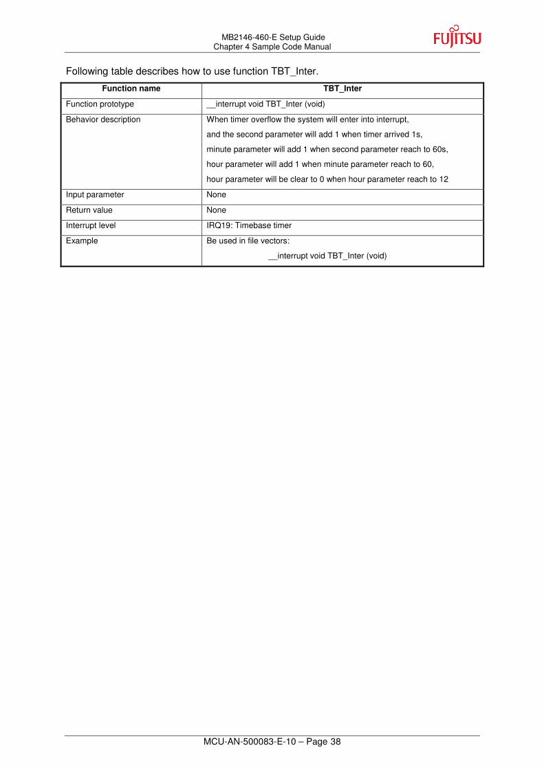
Following table describes how to use function TBT_Inter.
Function name TBT_Inter
Function prototype __interrupt void TBT_Inter (void)
Behavior description When timer overflow the system will enter into interrupt,
and the second parameter will add 1 when timer arrived 1s,
minute parameter will add 1 when second parameter reach to 60s,
hour parameter will add 1 when minute parameter reach to 60,
hour parameter will be clear to 0 when hour parameter reach to 12
Input parameter None
Return value None
Interrupt level IRQ19: Timebase timer
Example Be used in file vectors:
__interrupt void TBT_Inter (void)
MB2146-460-E Setup Guide Chapter 4 Sample Code Manual
MCU-AN-500083-E-10 – Page 39
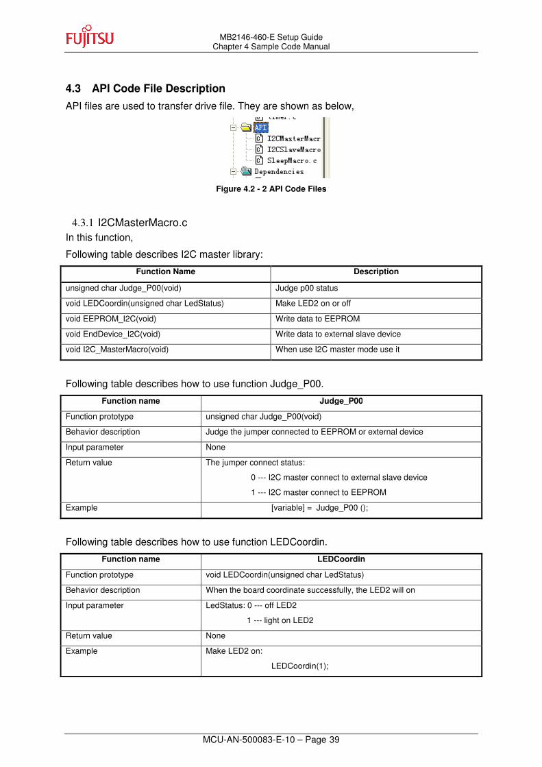
4.3 API Code File Description
API files are used to transfer drive file. They are shown as below,
Figure 4.2 - 2 API Code Files
4.3.1 I2CMasterMacro.c In this function,
Following table describes I2C master library:
Function Name Description
unsigned char Judge_P00(void) Judge p00 status
void LEDCoordin(unsigned char LedStatus) Make LED2 on or off
void EEPROM_I2C(void) Write data to EEPROM
void EndDevice_I2C(void) Write data to external slave device
void I2C_MasterMacro(void) When use I2C master mode use it
Following table describes how to use function Judge_P00.
Function name Judge_P00
Function prototype unsigned char Judge_P00(void)
Behavior description Judge the jumper connected to EEPROM or external device
Input parameter None
Return value The jumper connect status:
0 --- I2C master connect to external slave device
1 --- I2C master connect to EEPROM
Example [variable] = Judge_P00 ();
Following table describes how to use function LEDCoordin.
Function name LEDCoordin
Function prototype void LEDCoordin(unsigned char LedStatus)
Behavior description When the board coordinate successfully, the LED2 will on
Input parameter LedStatus: 0 --- off LED2
1 --- light on LED2
Return value None
Example Make LED2 on:
LEDCoordin(1);

MB2146-460-E Setup Guide Chapter 4 Sample Code Manual
MCU-AN-500083-E-10 – Page 40
Following table describes how to use function EEPROM_I2C.
Function name EEPROM_I2C
Function prototype void EEPROM_I2C(void)
Behavior description When Judge_P00(void) function return 1, IIC0 will write data to EEPROM when “send” key pressed
Input parameter None
Return value None
Example IIC0 write data to EEPROM:
EEPROM_I2C();
Following table describes how to use function EndDevice_I2C.
Function name EndDevice_I2C
Function prototype void EndDevice_I2C(void)
Behavior description When Judge_P00(void) function return 0, IIC0 will write data to external slave device, when “send” key pressed
Input parameter None
Return value None
Example IIC0 write data to external slave device:
EndDevice_I2C();
Following table describes how to use function I2C_MasterMacro.
Function name I2C_MasterMacro
Function prototype void I2C_MasterMacro(void)
Behavior description when “send” key pressed will write data to slave device
Input parameter None
Return value None
Example Used in main.c:
I2C_MasterMacro();

MB2146-460-E Setup Guide Chapter 4 Sample Code Manual
MCU-AN-500083-E-10 – Page 41
4.3.2 I2CSlaveMacro.c Following table describes the I2C slave library:
Function Name Description
void I2C_SlaveMacro(void) Decide MCU address
When IIC0 is connected to multiple slaves, these five constants are used decide which one to access.
Following table describes how to use function I2C_SlaveMacro.
Function name I2C_SlaveMacro
Function prototype void I2C_SlaveMacro(void)
Behavior description Set MCU address
Input parameter None
Return value None
Example Used in main.c:
I2C_SlaveMacro();
Note: the MCU address register IAAR1 must set to the value half of MCU address.

MB2146-460-E Setup Guide Chapter 4 Sample Code Manual
MCU-AN-500083-E-10 – Page 42
4.3.3 SleepMacro.c In this function,
Following table describes the sleep library:
Function Name Description
void Sleep_Macro(void) Make system enter into stop mode
Following table describes how to use function Sleep_Macro.
Function name Sleep_Macro
Function prototype void Sleep_Macro(void)
Behavior description Make system enter into stop mode
Input parameter None
Return value None
Example Used in main.c:
Sleep_Macro();

MB2146-460-E Setup Guide Chapter 4 Sample Code Manual
MCU-AN-500083-E-10 – Page 43
4.4 Global Variable Description
Five drive files are available in this project shown below,
� _f2mc8fx.h
_f2mc8fx.h is system-defined document. Ignore it
� mb95350l.h
Mb95350l.h is system-defined document. Ignore it
� def.h
This file basically includes all global variables of FW
Following picture describes the global variable.
typedef struct
{
unsigned char CoordiFlag; //flag for slave and master coordinate is successfully
unsigned char DatSlavI2CRead; //slave i2c read data
unsigned char KeyStatus; //record key status
unsigned char AddrMCU; //slave i2c address
}Global;
typedef struct
{
unsigned char TBT_Hour; //RTC hour
unsigned char TBT_Minute; //RTC minute
unsigned char TBT_Second; //RTC second
unsigned int TBT_Tim; //RTC add number every 0.65ms
unsigned char ErrorDet; //detect error enter dead while
unsigned char ErrorFlag; //flag for dead while out time
unsigned int DeadWhile_Tim; //count after enter dead while
}RTCPar;
#define AddrEEPROM 0xa0

MB2146-460-E Setup Guide Chapter 4 Sample Code Manual
MCU-AN-500083-E-10 – Page 44
4.5 How to Add These Files
Before using files in section 4.2, please refer to the following steps.
� Create a new project
� Copy .c file to project document
� Add .c file to project
� Add all needed .c files to project

MB2146-460-E Setup Guide Chapter 4 Sample Code Manual
MCU-AN-500083-E-10 – Page 45
4.6 Usage Demo
Following table list all C file.
4.6.1 Code of main.c listed as following:
4.6.2 Code of Initial_ADC listed as following:
InitIrqLevels(); // Initialize Interrupt level register and IRQ vector table
Initial();
Initial_ADC();
Init_EXT();
TBT_Init();
__EI ();
While (1)
{
I2C_SlaveMacro (); // Set as slave mode and set a slave address
I2C_MasterMacro ();
Sleep_Macro(); // Go to sleep
}
AIDRL_P00 = 0; //anologe input
DDR0_P00 = 0; //input
ADC1 = 0x00; //start adc, clear interrupt, AN00 selected
ADC2 = 0x80;

MB2146-460-E Setup Guide Chapter 4 Sample Code Manual
MCU-AN-500083-E-10 – Page 46
4.6.3 Code of Read_ADC listed as following
4.6.4 Code of Judge_SlaveAddr listed as following
unsigned char i=0,j=0, Vadc;
unsigned int k=0;
for(i=0;i<8;i++)
{
ADC1=0x01;
While (!ADC1_ADI);
j++;
k=k+ADD_ADDL;
}
Vadc = k/8;
ADC1_ADI = 0; //clear interrupt
return Vadc;
unsigned char ReturValu;
if((0 <= AddrJudg)&&(AddrJudg <= 0x03))
ReturValu = 0x10;
else if((0x04 <= AddrJudg)&&(AddrJudg <= 0x34))
ReturValu = 0x20;
else if((0x35 <= AddrJudg)&&(AddrJudg <= 0x85))
ReturValu = 0x30;
else if((0x86 <= AddrJudg)&&(AddrJudg <= 0xcc))
ReturValu = 0x40;
else
ReturValu = 0x50;
return ReturValu;

MB2146-460-E Setup Guide Chapter 4 Sample Code Manual
MCU-AN-500083-E-10 – Page 47
4.6.5 Code of Init_EXT listed as following
4.6.6 Code of INTER_EXT listed as following
4.6.7 Code of I2C_Init listed as following
DDR0_P04 = 0; //input
PUL0_P04 = 0; //disable pull up
AIDRL_P04 = 1; //i/o port use
EIC20 = 0x05;
EIC20_EIR0 = 0;
PraGlo.KeyStatus = 1; //key pressed
ICCR0_EN = 0; // clear I2C interface
ICCR0_CS4 = 0; // set clock divider 'm' => 5
ICCR0_CS3 = 0;
ICCR0_CS2 = 1; // set clock divider 'n' => 98
ICCR0_CS1 = 0;
ICCR0_CS0 = 0; // Fsck = MCLK / (m * n +2) => 3MHz/(5*98 +2)
//= 3MHz/492 = 6.1kHz
IDDR0 = 0x00; // clear data register
IBCR00 = 0x00; // enable address acknowledge bit,
// transfer completion interrupt after nine cycles,
// enable stop detection interrupt
IBCR10 = 0x08; // set to slave mode first, disable data acknowledge bit,
// disable bus error and transfer complete interrupt
ICCR0_EN = 1; // enable I2C interface

MB2146-460-E Setup Guide Chapter 4 Sample Code Manual
MCU-AN-500083-E-10 – Page 48
4.6.8 Code of Read_I2C listed as following
4.6.9 Code of Write_I2C listed as following
4.6.10 Code of Initial listed as following
unsigned char Temp;
I2C_Init ();
I2C_Start (DevAddr); // Write Comand to ...
I2C_Acknowlegde ();
I2C_Write (SubAddr); // ... set address from where to read
I2C_Continue (DevAddr+1) ; // Restart, with READ comand
Temp = I2C_LastRead (); // receive data from
I2C_Stop ();
return (Temp);
I2C_Init ();
I2C_Start (DevAddr);
I2C_Acknowlegde ();
I2C_Write (SubAddr);
I2C_Write (WDat);
I2C_Stop ();
PraGlo.KeyStatus = 0; //intial key status is not pressed
PraGlo.CoordiFlag = 0; //initial coordinate LED to off
PraRtc.ErrorDet = 0; //initial error detected for dead while to 0

MB2146-460-E Setup Guide Chapter 4 Sample Code Manual
MCU-AN-500083-E-10 – Page 49
4.6.11 Code of SlaveI2C_PrepareForInterlisted as following
ICCR1_EN = 0;
ILSR_P16 = 1; //coms level
ILSR_P17 = 1;
DDR1_P16 = 0;
DDR1_P17 = 0;
ICCR1_EN = 0; // clear I2C interface
ICCR1_CS4 = 0; // set clock divider 'm' => 6
ICCR1_CS3 = 1 ;
ICCR1_CS2 = 0; // set clock divider 'n' => 4
ICCR1_CS1 = 0;
ICCR1_CS0 = 0; // Fsck = MCLK / (m * n +2) => 3MHz/(6*4 +2)
//= 3MHz/26 = 115kHz
ICCR1_EN = 1; // enable I2C interface
IDDR1 = 0x00; // clear data register
IBCR01 = 0x05;//0x04; // enable address acknowledge bit,
// transfer completion interrupt after nine cycles,
// enable stop detection interrupt
IBCR11 = 0x4A; // set slave mode, enable data acknowledge bit,
// enable bus error and transfer complete interrupt

MB2146-460-E Setup Guide Chapter 4 Sample Code Manual
MCU-AN-500083-E-10 – Page 50
4.6.12 Code of INTER_I2CSlaveModeWakeUp as following
IBCR01_WUE = 0; //disable i2c wake up interrupt
if (IBCR01_SPF == 0x01) // stop condition detected
{
IBCR01_SPF = 0x00; // clear stop condition
}
if (IBCR11_INT == 0x01) // transfer completed
{
ReaDat = IDDR1;
Tim ++;
if(Tim == 2)
{
Tim = 0;
PraGlo.DatSlavI2CRead = ReaDat;
PraGlo.CoordiFlag = 1; //slave address receive is same as mcu address
}
IBCR11_INT = 0x00; // clear bit
DDR0_P05 = 1;
PDR0_P05 = 0;
}
if(IBCR11_BER == 0x01) // bus error detected
{
IBCR11_BER = 0x00; // bit cleared
}

MB2146-460-E Setup Guide Chapter 4 Sample Code Manual
MCU-AN-500083-E-10 – Page 51
4.6.13 Code of STBLED_ON as following
4.6.14 Code of Write_StandBy as following
4.6.15 Code of Clock_Init as following
if(LEDSwiDat == 1)
{
PDR0_P07 = 0; //on
DDR0_P07 = 1;
}
else
{
PDR0_P07 = 1; //off
DDR0_P07 = 1;
}
STBLED_ON(1); //LED on
SYCC = 0x00; //main clock
SYCC2 = 0x21;//0x34;
While (STBC_MCRDY==0);
SlaveI2C_PrepareForInter ();
IBCR01_WUE = 1; //enable i2c wake up
while (IBSR1_BB);
STBC = 0x80; //Stop ENTERED
STBLED_ON(0); //LED OFF
Delay(60);
SYSC = 0x05; //enable reset, enable I2C1 pin,select PF/PG is clock use
SYCC = 0x00; //main clock
SYCC2 = 0xe1;
While (STBC_MCRDY==0);

MB2146-460-E Setup Guide Chapter 4 Sample Code Manual
MCU-AN-500083-E-10 – Page 52
4.6.16 Code of TBT_Tim_Init as following
4.6.17 Code of TBT_Init as following
PraRtc.TBT_Hour = 0; //clear hour
PraRtc.TBT_Minute = 0; //clear minute
PraRtc.TBT_Second = 0; //clear second
PraRtc.TBT_Tim == 0; //clear counter
TBT_Tim_Init();
Clock_Init();
TBTC = 0x4b; //enable interrupt,clear interrrupt,clear timer,0.35ms interval

MB2146-460-E Setup Guide Chapter 4 Sample Code Manual
MCU-AN-500083-E-10 – Page 53
4.6.18 Code of TBT_Inter as following
PraRtc.TBT_Tim++;
if(PraRtc.ErrorDet == 1)
{
PraRtc.DeadWhile_Tim ++;
if(PraRtc.DeadWhile_Tim == 1474) //1s
{
PraRtc.ErrorFlag = 1;
PraRtc.DeadWhile_Tim = 0;
PraRtc.ErrorDet = 0;
}
}
if(PraRtc.TBT_Tim == 1474) //1538*0.65=1s
{
PraRtc.TBT_Second++;
PraRtc.TBT_Tim = 0;
}
if(PraRtc.TBT_Second == 60)
{
PraRtc.TBT_Minute ++;
PraRtc.TBT_Second = 0;
}
if(PraRtc.TBT_Minute == 60)
{
PraRtc.TBT_Hour++;
PraRtc.TBT_Minute = 0;
}
if(PraRtc.TBT_Hour == 12)
{
PraRtc.TBT_Hour = 0;
}
TBTC_TBIF = 0; //clear interrupt

MB2146-460-E Setup Guide Chapter 4 Sample Code Manual
MCU-AN-500083-E-10 – Page 54
4.6.19 Code of Judge_P00 as following
4.6.20 Code of LEDCoordin as following
unsigned char StatuP0;
DDR6_P64 = 0;
StatuP0 = PDR6_P64;
return StatuP0;
switch(LedStatus)
{
case 0x00: //off
DDR0_P06 = 1;
PDR0_P06 = 1;
break;
case 0x01: //on
DDR0_P06 = 1;
PDR0_P06 = 0;
break;
}
MB2146-460-E Setup Guide Chapter 4 Sample Code Manual
MCU-AN-500083-E-10 – Page 55
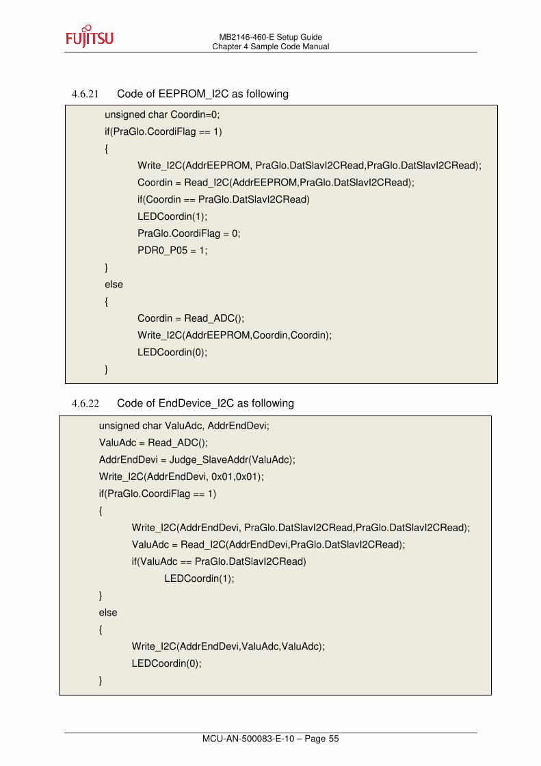
4.6.21 Code of EEPROM_I2C as following
4.6.22 Code of EndDevice_I2C as following
unsigned char Coordin=0;
if(PraGlo.CoordiFlag == 1)
{
Write_I2C(AddrEEPROM, PraGlo.DatSlavI2CRead,PraGlo.DatSlavI2CRead);
Coordin = Read_I2C(AddrEEPROM,PraGlo.DatSlavI2CRead);
if(Coordin == PraGlo.DatSlavI2CRead)
LEDCoordin(1);
PraGlo.CoordiFlag = 0;
PDR0_P05 = 1;
}
else
{
Coordin = Read_ADC();
Write_I2C(AddrEEPROM,Coordin,Coordin);
LEDCoordin(0);
}
unsigned char ValuAdc, AddrEndDevi;
ValuAdc = Read_ADC();
AddrEndDevi = Judge_SlaveAddr(ValuAdc);
Write_I2C(AddrEndDevi, 0x01,0x01);
if(PraGlo.CoordiFlag == 1)
{
Write_I2C(AddrEndDevi, PraGlo.DatSlavI2CRead,PraGlo.DatSlavI2CRead);
ValuAdc = Read_I2C(AddrEndDevi,PraGlo.DatSlavI2CRead);
if(ValuAdc == PraGlo.DatSlavI2CRead)
LEDCoordin(1);
}
else
{
Write_I2C(AddrEndDevi,ValuAdc,ValuAdc);
LEDCoordin(0);
}

MB2146-460-E Setup Guide Chapter 4 Sample Code Manual
MCU-AN-500083-E-10 – Page 56
4.6.23 Code of I2C_MasterMacro as following
4.6.24 Code of I2C_SlaveMacro as following
4.6.25 Code of Sleep_Macro as following
if(PraGlo.KeyStatus == 1)
{
P00Status = Judge_P00 ();
if(P00Status == 1)
EEPROM_I2C ();
else
EndDevice_I2C ();
}
PraGlo.KeyStatus = 0;
unsigned char ReadADC;
ReadADC = Read_ADC();
PraGlo.AddrMCU = Judge_SlaveAddr(ReadADC);
IAAR1 = (PraGlo.AddrMCU>>1);
Write_StandBy();

MB2146-460-E Setup Guide Chapter 5 Development Platform Quick Start
MCU-AN-500083-E-10 – Page 57
5 Development Platform Quick Start
5.1 Tools Setup Sequence
Start the debugging system in the following sequence:
� Connect a BGMA to the PC with a USB cable, confirm whether the LED on the BGMA is green;
� Connect an EV-board to BGMA IDC10 socket;
� Select the EV-board power supply and turn on the EV-board, confirm whether the LED on the BGMA is orange and the Power LED on the EV-board is on.
5.2 Open Project and Start Debug
Users can start a debug from a PC software SOFTUNE workbench in the following sequence. Take SIMULATE LCD EVBOARD project as an example.
� Start the SOFTUNE from “Startup Menu>Programs> SOFTUNE V3> FFMC-8L Family SOFTUNE Workbench” in Windows;
� Click “Open workspace” from “File” Menu in SOFTUNE;
� Select “SIMULATE LCD EVBOARD.wsp” in “Open Space” window;
� Click “Start debug” from “Debug” Menu.
If the entire procedure goes right, a debug will start normally.
5.3 Operation Precautions
� All pins of MB95350L Series MCU are connected to Testing Pin on the EV-board. If user wants to test the performance of a single pin, please connect it to the test pin.
� Note: before connecting with BGMA, do not power on system.
� It’s recommended that only one power supply is used as a power module input at a time.

MCU-AN-500083-E-10
FUJITSU Microelectronics LIMITED • SUPPORT SYSTEM
F2MC-8FX Family MB95350L Series
EV-Board
MB2146-460-E
SETUP GUIDE
MAR. 2010 the second edition
Published FUJITSU Microelectronics LIMITED
Edited Strategic Business Development Dept