Embed Size (px)
Citation preview
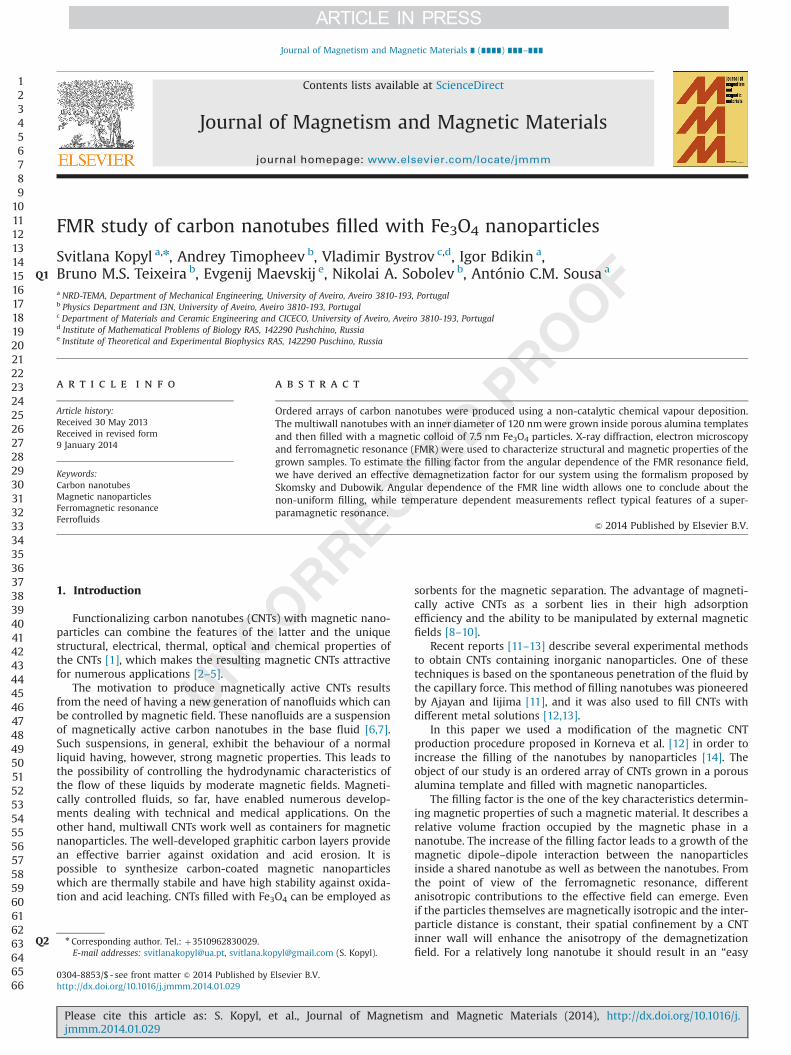
FMR study of carbon nanotubes filled with Fe3O4 nanoparticles
Svitlana Kopyl a,n, Andrey Timopheev b, Vladimir Bystrov c,d, Igor Bdikin a,Bruno M.S. Teixeira b, Evgenij Maevskij e, Nikolai A. Sobolev b, António C.M. Sousa a
Q1
a NRD-TEMA, Department of Mechanical Engineering, University of Aveiro, Aveiro 3810-193, Portugalb Physics Department and I3N, University of Aveiro, Aveiro 3810-193, Portugalc Department of Materials and Ceramic Engineering and CICECO, University of Aveiro, Aveiro 3810-193, Portugald Institute of Mathematical Problems of Biology RAS, 142290 Pushchino, Russiae Institute of Theoretical and Experimental Biophysics RAS, 142290 Puschino, Russia
a r t i c l e i n f o
Article history:Received 30 May 2013Received in revised form9 January 2014
Keywords:Carbon nanotubesMagnetic nanoparticlesFerromagnetic resonanceFerrofluids
a b s t r a c t
Ordered arrays of carbon nanotubes were produced using a non-catalytic chemical vapour deposition.The multiwall nanotubes with an inner diameter of 120 nmwere grown inside porous alumina templatesand then filled with a magnetic colloid of 7.5 nm Fe3O4 particles. X-ray diffraction, electron microscopyand ferromagnetic resonance (FMR) were used to characterize structural and magnetic properties of thegrown samples. To estimate the filling factor from the angular dependence of the FMR resonance field,we have derived an effective demagnetization factor for our system using the formalism proposed bySkomsky and Dubowik. Angular dependence of the FMR line width allows one to conclude about thenon-uniform filling, while temperature dependent measurements reflect typical features of a super-paramagnetic resonance.
& 2014 Published by Elsevier B.V.
1. Introduction
Functionalizing carbon nanotubes (CNTs) with magnetic nano-particles can combine the features of the latter and the uniquestructural, electrical, thermal, optical and chemical properties ofthe CNTs [1], which makes the resulting magnetic CNTs attractivefor numerous applications [2–5].
The motivation to produce magnetically active CNTs resultsfrom the need of having a new generation of nanofluids which canbe controlled by magnetic field. These nanofluids are a suspensionof magnetically active carbon nanotubes in the base fluid [6,7].Such suspensions, in general, exhibit the behaviour of a normalliquid having, however, strong magnetic properties. This leads tothe possibility of controlling the hydrodynamic characteristics ofthe flow of these liquids by moderate magnetic fields. Magneti-cally controlled fluids, so far, have enabled numerous develop-ments dealing with technical and medical applications. On theother hand, multiwall CNTs work well as containers for magneticnanoparticles. The well-developed graphitic carbon layers providean effective barrier against oxidation and acid erosion. It ispossible to synthesize carbon-coated magnetic nanoparticleswhich are thermally stabile and have high stability against oxida-tion and acid leaching. CNTs filled with Fe3O4 can be employed as
sorbents for the magnetic separation. The advantage of magneti-cally active CNTs as a sorbent lies in their high adsorptionefficiency and the ability to be manipulated by external magneticfields [8–10].
Recent reports [11–13] describe several experimental methodsto obtain CNTs containing inorganic nanoparticles. One of thesetechniques is based on the spontaneous penetration of the fluid bythe capillary force. This method of filling nanotubes was pioneeredby Ajayan and Iijima [11], and it was also used to fill CNTs withdifferent metal solutions [12,13].
In this paper we used a modification of the magnetic CNTproduction procedure proposed in Korneva et al. [12] in order toincrease the filling of the nanotubes by nanoparticles [14]. Theobject of our study is an ordered array of CNTs grown in a porousalumina template and filled with magnetic nanoparticles.
The filling factor is the one of the key characteristics determin-ing magnetic properties of such a magnetic material. It describes arelative volume fraction occupied by the magnetic phase in ananotube. The increase of the filling factor leads to a growth of themagnetic dipole–dipole interaction between the nanoparticlesinside a shared nanotube as well as between the nanotubes. Fromthe point of view of the ferromagnetic resonance, differentanisotropic contributions to the effective field can emerge. Evenif the particles themselves are magnetically isotropic and the inter-particle distance is constant, their spatial confinement by a CNTinner wall will enhance the anisotropy of the demagnetizationfield. For a relatively long nanotube it should result in an “easy
123456789
101112131415161718192021222324252627282930313233343536373839404142434445464748495051525354555657585960616263646566
Contents lists available at ScienceDirect
journal homepage: www.elsevier.com/locate/jmmm
Journal of Magnetism and Magnetic Materials
0304-8853/$ - see front matter & 2014 Published by Elsevier B.V.http://dx.doi.org/10.1016/j.jmmm.2014.01.029
nQ2 Corresponding author. Tel.: þ3510962830029.E-mail addresses: [email protected], [email protected] (S. Kopyl).
Please cite this article as: S. Kopyl, et al., Journal of Magnetism and Magnetic Materials (2014), http://dx.doi.org/10.1016/j.jmmm.2014.01.029i
Journal of Magnetism and Magnetic Materials ∎ (∎∎∎∎) ∎∎∎–∎∎∎

axis” magnetic anisotropy. At the same time, our sample is a2D-array of 5 mm-long nanotubes, oriented perpendicularly to thefilm surface. As the lateral dimensions of the sample are severalorders of magnitude higher than its thickness, such a systemshould demonstrate an “easy plane” anisotropy, the magnitude ofwhich will be dependent on the mean distance between the CNTs.Thus, a competition between the “easy axis” and “easy plane”contributions must have a place in this system, and which of themwill dominate is directly dependent on the geometrical para-meters of our system, while the volume fraction is expected toinfluence only the magnitude of the overall anisotropy. Thereforethe ferromagnetic resonance, accompanied by the microscopy todetermine the geometric parameters, is a suitable method to studythe magnetic properties of such a hierarchically-heterogeneousmagnetic system.
2. Materials and methods
2.1. Carbon nanotubes production
CNTs were produced in the NRD laboratory (TEMA, Universityof Aveiro) by a non-catalytic chemical vapour deposition techniquebased on the pyrolysis of ethylene. The procedure was similar tothat reported by Korneva et al. [12]. For the preparation of theCNTs and prior to the chemical vapour deposition (CVD), thealumina template membranes (Whatmans Inc., U.K.) with dia-meter, thickness and pore size of 13 mm, 60 μm and 0.2 μm,respectively, were placed vertically inside the quartz tube wherethe CVD takes place; the nanotubes were formed in straightcylindrical pores which run through the membrane thickness.The pore diameter and thickness of the membrane determine thedimensions of the nanotubes.
The microstructures of the alumina membrane, the CNT sam-ples inside the membrane and the CNTs released from themembrane were observed in a Hitachi SU-70 scanning electronmicroscope (SEM) operated at 15 kV (University of Aveiro). TheSEM images of the alumina membranes reveal that the pores havevarying diameters within one sample. The pore diameter in thetested samples was in the range of 200715 nm [15].
The resulting CNTs have at least one open end (Fig. 1), and theirwalls are highly disordered and amorphous—these features favourthe filling of the nanotubes with both organic and water-basedfluids, as noted in Refs. [12,16]. The average length of the CNTs is6 μm. The size of the membrane pores with CNTs inside wascharacterized using atomic force microscopy (AFM). The AFMmeasurements were conducted with a commercial AFM (Ntegra,
NT-MDT, CICECO, University of Aveiro). Analysis of the AFM imagesindicates that most of the carbon nanotubes have an innerdiameter of about �120 nm [17].
The samples were analyzed and compared using a SiemensD500 X-ray diffractometer (University of Aveiro) setup (CuKαradiation). The diffraction patterns were recorded at room tem-perature in the range 10–701 with steps of 0.021.
2.2. CNT filling procedure
The filling procedure is described in detail in Ref. [17]; there-fore, only a short description will be given here for the sake ofcompleteness. The organics-based ferrofluid EMG 911 (FerrotecCorporation) with Fe3O4 nanoparticles (5–10 nm) was used in theprocess. The experimental approach proposed in [12,13] wasmodified as follows: (a) the loading was conducted by adding a100-fold excess (by weight) of the ferrofluid to the system; (b) nomagnetic field was used in this filling procedure; and (c) thesystem was left still for 24 h to allow impregnation after theloading was completed. In addition, the membrane was repeatedlyrinsed, first with hexane and then with ethanol; afterwards, it wasair-dried and broken into small pieces and dipped into 4.0 MNaOH solution for dissolving the alumina template for the electronmicroscopy analysis. The subsequent steps are described, asmentioned before, in Ref. [17]. The nanoparticle-filled CNTs werecharacterized using transmission electron microscopy (TEM) in aHitachi H-9000 microscope operated at 300 kV (University ofAveiro).
2.3. Ferromagnetic resonance
The FMR was measured at a Bruker ESP 300E EPR spectrometerusing a standard rectangular cavity. An out-of-plane experimentalconfiguration was used to investigate angular dependences of theFMR with the magnetic field oriented at an angle θh with respectto the normal of the film. These measurements were performed atroom temperature (RT) at a microwave frequency f0¼9.783 GHz.The temperature-dependent measurements were conducted fortwo main magnetic field orientations, namely, for the field alignedparallel (θh¼901) and perpendicular (θh¼01) to the film plane.A continuous-flow nitrogen cryostat was used for measurementsin the temperature range from 150 to 450 K. Due to the presenceof quartz inside the cavity its resonance frequency was lowered to9.465 GHz. All measurements were performed in the field rangefrom 50 Oe to 10,050 Oe with a modulation frequency of 100 kHz;for each measurement, the first derivative of the absorption signalwith respect to the magnetic field was registered.
3. Results and discussion
3.1. Carbon nanotubes with ferrofluid
A typical TEM image of CNTs filled with Fe3O4 nanoparticlesfrom an organic-based ferrofluid is shown in Fig. 2. The nanotubesfilled with nanoparticles can be easily identified in the image.
The table in Fig. 2 results from measurements using energy-dispersive X-ray spectroscopy (EDS) of the filled samples; thesemeasurements confirm the presence of iron in the CNTs. Toprevent the particles from coagulation, they are coated withsurfactant molecules whose polar head groups are attached tothe particle surfaces.
Fig. 3 shows typical X-ray diffraction (XRD) patterns of thealumina membrane, alumina membrane with CNTs, CNTs releasedfrom the alumina membrane and the magnetic CNT compositeinside the alumina membrane. According to the XRD diffraction
123456789
101112131415161718192021222324252627282930313233343536373839404142434445464748495051525354555657585960616263646566 Fig. 1. SEM image of CNTs after dissolving the alumina membrane.
S. Kopyl et al. / Journal of Magnetism and Magnetic Materials ∎ (∎∎∎∎) ∎∎∎–∎∎∎2
Please cite this article as: S. Kopyl, et al., Journal of Magnetism and Magnetic Materials (2014), http://dx.doi.org/10.1016/j.jmmm.2014.01.029i
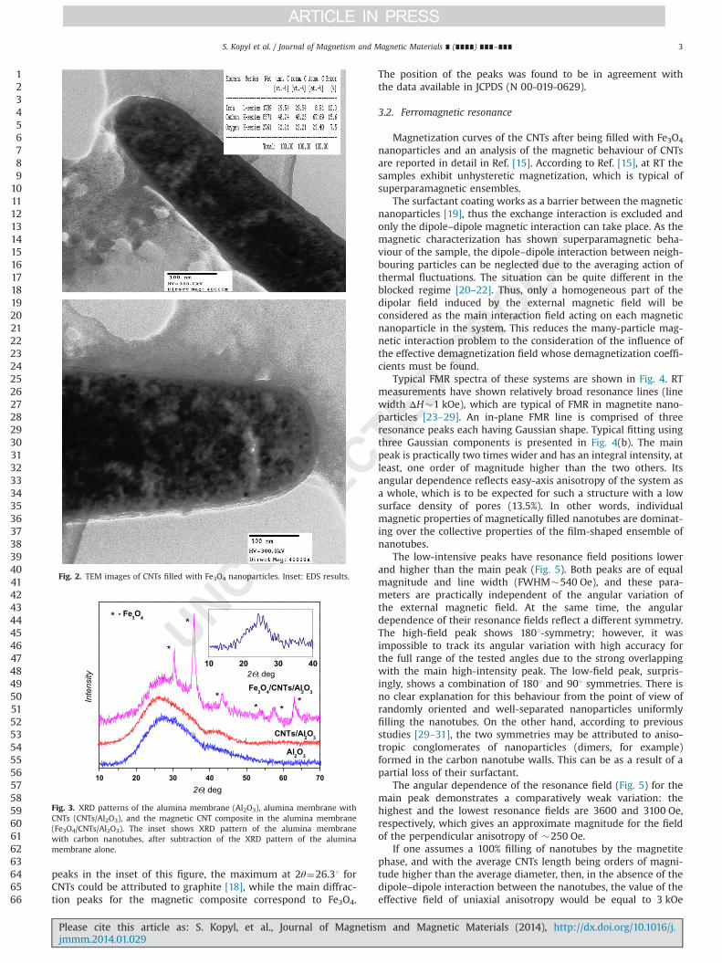
peaks in the inset of this figure, the maximum at 2θ¼26.31 forCNTs could be attributed to graphite [18], while the main diffrac-tion peaks for the magnetic composite correspond to Fe3O4.
The position of the peaks was found to be in agreement withthe data available in JCPDS (N 00-019-0629).
3.2. Ferromagnetic resonance
Magnetization curves of the CNTs after being filled with Fe3O4
nanoparticles and an analysis of the magnetic behaviour of CNTsare reported in detail in Ref. [15]. According to Ref. [15], at RT thesamples exhibit unhysteretic magnetization, which is typical ofsuperparamagnetic ensembles.
The surfactant coating works as a barrier between the magneticnanoparticles [19], thus the exchange interaction is excluded andonly the dipole–dipole magnetic interaction can take place. As themagnetic characterization has shown superparamagnetic beha-viour of the sample, the dipole–dipole interaction between neigh-bouring particles can be neglected due to the averaging action ofthermal fluctuations. The situation can be quite different in theblocked regime [20–22]. Thus, only a homogeneous part of thedipolar field induced by the external magnetic field will beconsidered as the main interaction field acting on each magneticnanoparticle in the system. This reduces the many-particle mag-netic interaction problem to the consideration of the influence ofthe effective demagnetization field whose demagnetization coeffi-cients must be found.
Typical FMR spectra of these systems are shown in Fig. 4. RTmeasurements have shown relatively broad resonance lines (linewidth ΔH�1 kOe), which are typical of FMR in magnetite nano-particles [23–29]. An in-plane FMR line is comprised of threeresonance peaks each having Gaussian shape. Typical fitting usingthree Gaussian components is presented in Fig. 4(b). The mainpeak is practically two times wider and has an integral intensity, atleast, one order of magnitude higher than the two others. Itsangular dependence reflects easy-axis anisotropy of the system asa whole, which is to be expected for such a structure with a lowsurface density of pores (13.5%). In other words, individualmagnetic properties of magnetically filled nanotubes are dominat-ing over the collective properties of the film-shaped ensemble ofnanotubes.
The low-intensive peaks have resonance field positions lowerand higher than the main peak (Fig. 5). Both peaks are of equalmagnitude and line width (FWHM�540 Oe), and these para-meters are practically independent of the angular variation ofthe external magnetic field. At the same time, the angulardependence of their resonance fields reflect a different symmetry.The high-field peak shows 1801-symmetry; however, it wasimpossible to track its angular variation with high accuracy forthe full range of the tested angles due to the strong overlappingwith the main high-intensity peak. The low-field peak, surpris-ingly, shows a combination of 1801 and 901 symmetries. There isno clear explanation for this behaviour from the point of view ofrandomly oriented and well-separated nanoparticles uniformlyfilling the nanotubes. On the other hand, according to previousstudies [29–31], the two symmetries may be attributed to aniso-tropic conglomerates of nanoparticles (dimers, for example)formed in the carbon nanotube walls. This can be as a result of apartial loss of their surfactant.
The angular dependence of the resonance field (Fig. 5) for themain peak demonstrates a comparatively weak variation: thehighest and the lowest resonance fields are 3600 and 3100 Oe,respectively, which gives an approximate magnitude for the fieldof the perpendicular anisotropy of �250 Oe.
If one assumes a 100% filling of nanotubes by the magnetitephase, and with the average CNTs length being orders of magni-tude higher than the average diameter, then, in the absence of thedipole–dipole interaction between the nanotubes, the value of theeffective field of uniaxial anisotropy would be equal to 3 kOe
123456789
101112131415161718192021222324252627282930313233343536373839404142434445464748495051525354555657585960616263646566
10 20 30 40 50 60 70
10 20 30 40
- Fe O*
***
*
*
*
Fe O /CNTs/Al O
CNTs/Al O
Al O
Inte
nsity
2Θ, deg
2Θ, deg
Fig. 3. XRD patterns of the alumina membrane (Al2O3), alumina membrane withCNTs (CNTs/Al2O3), and the magnetic CNT composite in the alumina membrane(Fe3O4/CNTs/Al2O3). The inset shows XRD pattern of the alumina membranewith carbon nanotubes, after subtraction of the XRD pattern of the aluminamembrane alone.
Fig. 2. TEM images of CNTs filled with Fe3O4 nanoparticles. Inset: EDS results.
S. Kopyl et al. / Journal of Magnetism and Magnetic Materials ∎ (∎∎∎∎) ∎∎∎–∎∎∎ 3
Please cite this article as: S. Kopyl, et al., Journal of Magnetism and Magnetic Materials (2014), http://dx.doi.org/10.1016/j.jmmm.2014.01.029i
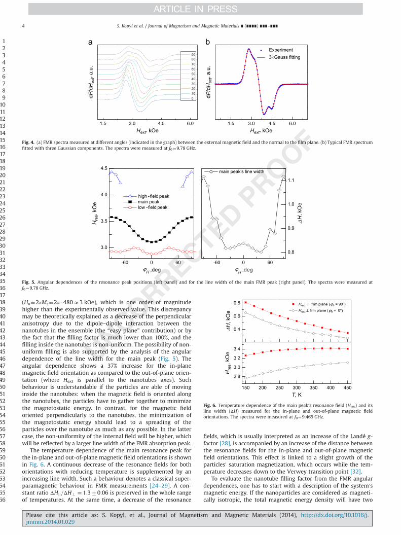
(Ha¼2πMs¼2π �480E3 kOe), which is one order of magnitudehigher than the experimentally observed value. This discrepancymay be theoretically explained as a decrease of the perpendicularanisotropy due to the dipole–dipole interaction between thenanotubes in the ensemble (the “easy plane” contribution) or bythe fact that the filling factor is much lower than 100%, and thefilling inside the nanotubes is non-uniform. The possibility of non-uniform filling is also supported by the analysis of the angulardependence of the line width for the main peak (Fig. 5). Theangular dependence shows a 37% increase for the in-planemagnetic field orientation as compared to the out-of-plane orien-tation (where Hext is parallel to the nanotubes axes). Suchbehaviour is understandable if the particles are able of movinginside the nanotubes: when the magnetic field is oriented alongthe nanotubes, the particles have to gather together to minimizethe magnetostatic energy. In contrast, for the magnetic fieldoriented perpendicularly to the nanotubes, the minimization ofthe magnetostatic energy should lead to a spreading of theparticles over the nanotube as much as any possible. In the lattercase, the non-uniformity of the internal field will be higher, whichwill be reflected by a larger line width of the FMR absorption peak.
The temperature dependence of the main resonance peak forthe in-plane and out-of-plane magnetic field orientations is shownin Fig. 6. A continuous decrease of the resonance fields for bothorientations with reducing temperature is supplemented by anincreasing line width. Such a behaviour denotes a classical super-paramagnetic behaviour in FMR measurements [24–29]. A con-stant ratio ΔHjj=ΔH? ¼ 1:370:06 is preserved in the whole rangeof temperatures. At the same time, a decrease of the resonance
fields, which is usually interpreted as an increase of the Landé g-factor [28], is accompanied by an increase of the distance betweenthe resonance fields for the in-plane and out-of-plane magneticfield orientations. This effect is linked to a slight growth of theparticles0 saturation magnetization, which occurs while the tem-perature decreases down to the Verwey transition point [32].
To evaluate the nanotube filling factor from the FMR angulardependences, one has to start with a description of the system0smagnetic energy. If the nanoparticles are considered as magneti-cally isotropic, the total magnetic energy density will have two
123456789
101112131415161718192021222324252627282930313233343536373839404142434445464748495051525354555657585960616263646566
dP/d
Hex
t, a.
u.
dP/d
Hex
t, a.
u.
Hext, kOe Hext, kOe
90 80 70 60 50 40 30 20 10 0
1.5 3.0 4.5 6.0 1.5 3.0 4.5 6.0
Experiment 3×Gauss fitting
Fig. 4. (a) FMR spectra measured at different angles (indicated in the graph) between the external magnetic field and the normal to the film plane. (b) Typical FMR spectrumfitted with three Gaussian components. The spectra were measured at f0¼9.78 GHz.
3.0
3.5
4.0
4.5
high - eld peakmain peaklow - eld peak
Hre
s, kO
e
ϕH ,deg ϕ
H ,deg-60 0 60 -60 0 60
0.8
0.9
1.0
1.1
main peak's line width
ΔH
, kO
e
Fig. 5. Angular dependences of the resonance peak positions (left panel) and for the line width of the main FMR peak (right panel). The spectra were measured atf0¼9.78 GHz.
150 200 250 300 350 400 450
2.8
3.0
3.2
3.4
Hre
s, kO
e
T, K
Hext || film plane (ϕh = 90º)Hext ⊥ film plane (ϕh = 0º)
0.4
0.6
0.8
ΔH
, kO
e
Fig. 6. Temperature dependence of the main peak0s resonance field (Hres) and itsline width (ΔH) measured for the in-plane and out-of-plane magnetic fieldorientations. The spectra were measured at f0¼9.465 GHz.
S. Kopyl et al. / Journal of Magnetism and Magnetic Materials ∎ (∎∎∎∎) ∎∎∎–∎∎∎4
Please cite this article as: S. Kopyl, et al., Journal of Magnetism and Magnetic Materials (2014), http://dx.doi.org/10.1016/j.jmmm.2014.01.029i

contributions:
Etot ¼ EdþEz; ð1Þwhere Ez is the Zeeman energy term expressing the interaction ofthe net magnetic moment with the external magnetic field Hext:
Ez ¼ �MsHext ð cos θm cos θhþ cos ðϕm�ϕhÞ sin θm sin θhÞ ð2ÞThe angular variables θh (polar angle read from a certain
direction in the film plane) and ϕh (azimuth angle read from thefilm normal) determine the external magnetic field orientation,while θm and ϕm give the film0s net magnetic moment orientation,respectively, and Ms stays for the particles saturation magnetiza-tion. Such a choice of the polar axis allows one to derive the Kittelequations for the in-plane and normal-to-plane cases directly fromthe Smith–Suhl formula.
The second term, Ed, is the magnetostatic energy which, accord-ing to Refs. [33,34], describes a thin film having an array ofperpendicularly oriented pores filled by nanoparticles. In our casethe magnetic nanoparticles are considered to be magneticallyisotropic. The internal demagnetization field of each particle willbe independent of its magnetic moment orientation, thus theeffective field will be zero for this case. The final expression will be:
Ed ¼M2
s
2ðf vf p4π� f pð1� f vÞ2πÞð cos ϕm sin θmÞ2; ð3Þ
where f v is the relative volume occupied by the pores in the film,and f p is the relative volume occupied by the particles in each pore.
To calculate the resonance field of a FMR line, the Smit–Beljersformalism was used, namely:∂Etot∂θm ¼ 0; ∂Etot
∂φm¼ 0;
ωγ
� �2¼ 1
ðMs sin θmÞ2∂2Etot∂θ2m
∂2Etot∂φ2
m� ∂2Etot
∂θm∂φm
� �� �9>=>;: ð4Þ
here γ ¼ ge=ð2mcÞ is the gyromagnetic ratio (g—spectroscopic Landéfactor, e—electron charge, m—electron mass, c—light velocity). TheKittel formula for the two main orientations of the magnetic field, i.e.those in-plane (θh ¼ 0; φh ¼ π=2) and out-of-plane (θh ¼ π=2;φh ¼ 0), can be analytically derived from Eqs. (1)–(4):
ðω=γÞ2 ¼HjjðHjj þ f pð4πf v�2πð1� f vÞÞMsÞ; ðθh ¼ 0;φh ¼ π=2Þ;ω=γ ¼H? þ f pð2πð1� f vÞ�4πf vÞMs; ðθh ¼ π=2;φh ¼ 0Þ: ð5Þ
For the intermediate orientations the system (4) has to besolved numerically.
Fig. 7 shows the best fit of an angular dependence of theresonance field for the main peak. The literature value of satura-tion magnetization for the bulk magnetite (480 emu/cm3) was
used [35]. The porosity parameter fp¼0.135 has been determinedfrom the AFM microscopy and was fixed, while the nanotubesfilling parameter f v and g-factor were free parameters in themodel fitting. The obtained parameters are fv¼0.188 andg¼2.043. The g-factor value obtained for T¼300 K is slightly lowerthan that for bulk magnetite (2.10–2.12) [35]. This is reasonablefrom the viewpoint of the observed superparamagnetic resonanceregime of the microwave absorption [24–28]. At temperaturesmuch higher than the blocking temperature, the superparamag-netic behavior leads to the experimentally observed, but theore-tically still not explained behavior: the g-factor approaches thefree electron value g¼2.0023. This is the so called “superpara-magnetic resonance” regime. As expected, in the temperaturerange from 450 to 150 K the temperature dependence of Hres forthe main peak (Fig. 6), using Eq. (5), yields a decrease of theg-factor from 2.04 to 2.18. Thus, at low temperatures the g-factorof our Fe3O4 nanoparticles is much closer to its bulk value. Here,however, a certain degree of speculation is present because ofthe ignorance of the cubic magnetocrystalline anisotropy of thenanoparticles and its temperature dependence. Moreover, theaccuracy of the resonance field determination for wide lines canalso play a significant role. Thus, a more in-depth discussion of theg-factor has no sense.
To finalize, we would like to emphasize that our modified produc-tion method of magnetic CNTs allows one to obtain a much higherfilling factor. To our opinion, this noticeable improvement owes toadding a 100-fold excess (by weight) of ferrofluid to the system [17].
4. Conclusions
An array of CNTs filled by magnetic nanoparticles has been grownin porous alumina templates. The growth included two stages. First,the multiwall CNTs with an inner diameter of 120 nm were synthe-sized by a non-catalytic CVD method, and then a magnetic colloidalsuspension of 7.5 nm Fe3O4 nanoparticles was inserted in them bycapillary force. X-ray diffraction and electron microscopy studies wereused to check the quality of the grown samples and to obtain theirgeometrical aspects. Ferromagnetic resonance was used to obtainqualitative and quantitative information on the magnetic properties ofthe system. Overall magnetic anisotropy of the system is determinedby a competition between the “easy axis”-type anisotropy, which is anindividual feature of each magnetically filled nanotube, and the “easyplane”-type anisotropy as a result of the array dimensionality and thepresent dipole–dipole interaction between the tubes. Namely, themagnetic anisotropy is set by the geometry of the system, while itsmagnitude is determined by the filling factor. The system is unblockedat RT and demonstrates all characteristic features of the “superpar-amagnetic resonance” regime in the FMR spectra. The filling factor(relative volume occupied by the magnetic phase in the inner volumeof the nanotubes) amounts to fv¼0.19, which has been determinedfrom the model fitting of the angular dependences of the FMR field.
Magnetically active CNTs are believed to be attractive for theproduction of magnetic nanofluids and in magnetic separationapplications.
Acknowledgements
This work has been supported the FCT of Portugal through projectsand grants PTDC/EME-MFE/105031/2008, PEst-C/CTM /LA0025/2011,RECI/FIS-NAN/0183/2012, SFRH/BPD/22230/2005, SFRH /BPD /74086/2010, REDE/1509/RME/2005, and European project “Mold-Nanonet”.
123456789
101112131415161718192021222324252627282930313233343536373839404142434445464748495051525354555657585960616263646566
-90 -60 -30 0 30 60 90
3.1
3.2
3.3
3.4
3.5
3.6
3.7
Hre
s, kO
e
ϕh, Deg.
fitting experiment
Fig. 7. Model fitting with the fixed parameters: ω¼ 2π � 9:78� 109 rad=s,f p ¼ 0:32, Ms ¼ 480 emu=cm3. Fitted parameters: f v ¼ 0:188, g¼ 2:043.
S. Kopyl et al. / Journal of Magnetism and Magnetic Materials ∎ (∎∎∎∎) ∎∎∎–∎∎∎ 5
Please cite this article as: S. Kopyl, et al., Journal of Magnetism and Magnetic Materials (2014), http://dx.doi.org/10.1016/j.jmmm.2014.01.029i
References
[1] R. Klingeler, R.B. Sim (Eds.), Carbon Nanotubes for Biomedical Applications,Springer, Berlin, Heidelberg, ISBN 978-3-642-14801-9, 2011.
[2] H. Zeng, S. Sun, Syntheses, properties, and potential applications of multi-component magnetic nanoparticles, Adv. Funct. Mater. 18 (2008) 391–400.
[3] M. Roldo, D.G. Fatouros, Biomedical applications of carbon nanotubes, Annu.Rep. Prog. Chem. Sect. C: Phys. Chem. 109 (2013) 10–35.
[4] S. Qu, F. Huang, S. Yu, G. Chen, J. Kong, Magnetic removal of dyes from aqueoussolution using multi-walled carbon nanotubes filled with Fe2O3 particles, J.Hazard. Mater. 160 (2008) 643–647.
[5] A. Candini, S. Klyatskaya, M. Ruben, W. Wernsdorfer, M. Affronte, Graphenespintronic devices with molecular nanomagnets, Nano Lett. 11 (2011)2634–2639.
[6] L. Godson, B. Raja, D. Mohan Lal, S. Wongwises, Enhancement of heat transferusing nanofluids—an overview, Renewable Sustainable Energy Rev. 14 (2010)629–641.
[7] R. Saidur, K. Leong, H. Mahammad, A review on applications and challenges ofnanofluids, Renewable Sustainable Energy Rev. 15 (2011) 1646–1668.
[8] A.M.G.C. Dias, A. Hussain, A.S. Marcos, A.C.A. Roque, A biotechnologicalperspective on the application of iron oxide magnetic colloids modified withpolysaccharides, Biotechnol. Adv. 29 (2011) 142–155.
[9] S. El-Safty, A. Shahat, H. Nguyen, Nano-model membrane filters for the well-controlled separation of biomolecules, Colloids Surf., A 377 (2011) 44–53.
[10] X.-S. Li, G.-T. Zhu, Y.-B. Luo, B.-F. Yuan, Y.-Q. Feng, Synthesis and applications offunctionalized magnetic materials in sample preparation, Trends Anal. Chem.45 (2013) 233–247.
[11] P.M. Ajayan, S. Iijima, Capillarity-induced filling of carbon nanotubes, Nature361 (1993) 333–334.
[12] G. Korneva, H. Ye, Y. Gogotsi, D. Halverson, G. Friedman, J.-C. Bradley,K.G. Kornev, Carbon nanotubes loaded with magnetic particles, Nano Lett. 5(2005) 879–884 (5).
[13] S. Pal, S. Chandra, M.H. Phan, P. Mukherjee, H Srikanth, Carbon nanostraws:nanotubes filled with superparamagnetic nanoparticles, Nanotechnology 20(2009) 485604.
[14] S. Sundar, E.V. Ramana, M.K. Singh, A.C.M. Sousa, Viscosity of low volumeconcentrations of magnetic Fe3O4 nanoparticles dispersed in ethylene glycoland water mixture, Chem. Phys. Lett. 554 (2012) 236–242.
[15] S. Kopyl, V. Bystrov, M. Maiorov, M. Valente, I. Bdikin, A.C.M. Sousa, Carbonnanotubes with magnetic particles, in: Proceedings of World Academy ofScience, Engineering and Technology (Zurich, Switzerland), 67 (2012) 137–141.
[16] D. Mattia, Y. Gogotsi, Review: static and dynamic behaviour of liquids insidecarbon nanotubes, Microfluid. Nanofluid. 5 (2008) 289–305.
[17] S. Kopyl, V. Bystrov, M. Maiorov, I. Bdikin, A.C.M. Sousa, Filling the carbonnanotubes with magnetic particles, J. Mater. Chem. C 1 (2013) 2860–2866.
[18] G. Pilatos, E.C. Vermisoglou, G.E. Romanos, G.N. Karanikolos, N. Boukos,V. Likodimos, N.K. Kanellopoulos, Nanotubes: a closer look inside nanotubes:pore structure evaluation of anodized alumina templated carbon nanotubemembranes through adsorption and permeability studies, Adv. Funct. Mater.,20, 2500–2510 (15).
[19] J. Salado, M. Insausti, L. Lesama, I.G. Muro, E. Goikolea, T. Rojo, Preparation andcharacterization of monodisperse Fe3O4 nanoparticles: an electron magneticresonance study, Chem. Mater 23 (2011) 2879–2885.
[20] A.A. Timopheev, V.M. Kalita, S.M. Ryabchenko, A.F. Lozenko, P.A. Trotsenko,A.V. Los, M. Munakata, Coercivity anomaly in the superferromagnetic state ofan ensemble of nanoparticles with oriented anisotropy, J. Appl. Phys 108(2010) (053902-8).
[21] S.M. Ryabchenko, V.M. Kalita, A.F. Lozenko, P.A. Trotsenko, A.M. Grishin, A.A. Timopheev, P.A. Trotsenko, M. Munakata, Effect of interaction in themagnetization reversal relaxation of superparamagnetic granular CoFeB–SiO2 films, Solid State Phenom. 152 (2009) 213–216.
[22] V.M. Kalita, A.F. Lozenko, S.M. Ryabchenko, A.A. Timopheeev, R.A. Trotsenko,I.A. Danilenko, T.E. Konstantinova, Magnetic properties of La0.7Sr0.3MnO3
nanopowders, Low Temp. Phys. 34 (2008) 436–445.[23] S.A. Majetich, M. Sachan, Magnetostatic interactions in magnetic nanoparticle
assemblies: energy, time and length scales, J. Phys. D: Appl. Phys 39 (2006)R407–R422.
[24] B. Zapotoczny, M.R. Dudek, N. Guskos, J.J. Koziol, V.B. Padlyak, M. Kośmider,E. Rysiakiewicz-Pasek, FMR study of the porous silicate glasses with Fe3O4magnetic nanoparticles fillers, J. Nanomater. 2012 (2012) 341073.
[25] T. Bodziony, N. Guskos, Z. Roslaniec, U. Narkiewicz, M. Kwiatkowska,M. Maryniak, Low concentration effect of Fe3O4 and Fe3C magnetic nanopar-ticles in non-magnetic matrix on the FMR spectra, Acta Phys. Pol. A 108 (2005)297–302.
[26] O.N. Sorokina, A.V. Bychkova, A.L. Kovarskii, Analysis of the ferromagneticresonance spectra of aggregates of magnetite nanoparticles formed by amagnetic field, Russ. J. Phys. Chem. B 3 (2009) 257–261.
[27] N. Guskos, E.A. Anagnostakis, V. Likodimos, T. Bodziony, J. Typek, M. Maryniak,U. Narkiewicz, I. Kucharewicz, S. Waplak, Ferromagnetic resonance and acconductivity of a polymer composite of Fe3O4 and Fe3C nanoparticlesdispersed in a graphite matrix, J. Appl. Phys 97 (2005) 024304.
[28] J. Typek, N. Guskos, E. Filipek, Magneticinteractions in CrSbVO6 studied byEPR, J. Non-Cryst. Solids 354 (2008) 35–39 (4494–4499N).
[29] M. Noginov, N. Noginova, O. Amponsah, R. Bah, R.R. Rakhimov, V.A. Atsarkin,Magnetic resonance in iron oxide nanoparticles: quantum features and effectof size, J. Magn. Magn. Mater. 320 (2008) 2228–2232.
[30] S. Russ, A. Bunde, Monte Carlo simulations of frozen metastable states inordered systems of ultrafine magnetic particles, Phys. Rev. B: Condens. Matter74 (2006) 064426.
[31] M. Charilaou, M. Winklhofer, A. Gehring, Simulation of ferromagnetic reso-nanse spectra of linear chains of magnetite nanocrystals, J. Appl. Phys. 109(2011) 093903.
[32] E.J.W. Verwey, Electronic conduction of magnetite (Fe3O4) and its transitionpoint at low temperatures, Nature 144 (1939) 327–328.
[33] R. Skomski, G. Hadjipanayis, D. Salmeyr, Effective demagnetizing factors ofcomplicated particle mixtures, IEEE Trans. Magn. 43 (2007) 2956–2958.
[34] J. Dubowik, Share anisotropy of magnetic heterostructures, Phys. Rev. B:Condens. Matter 54 (1996) 1088–1091.
[35] Ü. Özgür, Y. Alivov, H. Morkoç, Microwave ferrites, Part 1: Fundamentalproperties, J. Mater. Sci.—Mater. Electron. 20 (2009) 789–834.
123456789
10111213141516171819202122232425262728293031323334353637383940
S. Kopyl et al. / Journal of Magnetism and Magnetic Materials ∎ (∎∎∎∎) ∎∎∎–∎∎∎6
Please cite this article as: S. Kopyl, et al., Journal of Magnetism and Magnetic Materials (2014), http://dx.doi.org/10.1016/j.jmmm.2014.01.029i