Embed Size (px)
Citation preview

LEGGI E CONSERVAQUESTE ISTRUZIONI
READ AND SAVE THESE INSTRUCTIONS
pCO3 - controllore elettronico / electronic controller
Technical leafl et
Foglio istruzioni
Betriebsanleitung
Mode d’emploi

Indice / Contents / Inhalt / Sommaire
Foglio istruzioni 3
Technical leafl et 15
Foglio istruzioni 23
Mode d’emploi 33
ELECTRICAL CONNECTIONS 38
13+050003290 - 1.4 - 29.09.2006
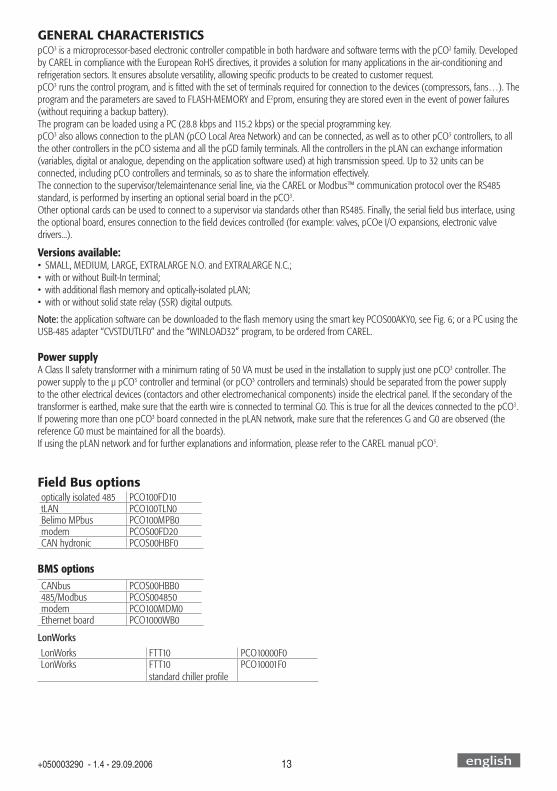
GENERAL CHARACTERISTICSpCO3 is a microprocessor-based electronic controller compatible in both hardware and software terms with the pCO2 family. Developed by CAREL in compliance with the European RoHS directives, it provides a solution for many applications in the air-conditioning and refrigeration sectors. It ensures absolute versatility, allowing specifi c products to be created to customer request.pCO3 runs the control program, and is fi tted with the set of terminals required for connection to the devices (compressors, fans…). The program and the parameters are saved to FLASH-MEMORY and E2prom, ensuring they are stored even in the event of power failures (without requiring a backup battery).The program can be loaded using a PC (28.8 kbps and 115.2 kbps) or the special programming key.pCO3 also allows connection to the pLAN (pCO Local Area Network) and can be connected, as well as to other pCO3 controllers, to all the other controllers in the pCO sistema and all the pGD family terminals. All the controllers in the pLAN can exchange information (variables, digital or analogue, depending on the application software used) at high transmission speed. Up to 32 units can be connected, including pCO controllers and terminals, so as to share the information effectively.The connection to the supervisor/telemaintenance serial line, via the CAREL or Modbus™ communication protocol over the RS485 standard, is performed by inserting an optional serial board in the pCO3.Other optional cards can be used to connect to a supervisor via standards other than RS485. Finally, the serial fi eld bus interface, using the optional board, ensures connection to the fi eld devices controlled (for example: valves, pCOe I/O expansions, electronic valve drivers...).
Versions available: • SMALL, MEDIUM, LARGE, EXTRALARGE N.O. and EXTRALARGE N.C.;• with or without Built-In terminal;• with additional fl ash memory and optically-isolated pLAN;• with or without solid state relay (SSR) digital outputs.
Note: the application software can be downloaded to the fl ash memory using the smart key PCOS00AKY0, see Fig. 6; or a PC using the USB-485 adapter “CVSTDUTLF0” and the “WINLOAD32” program, to be ordered from CAREL.
Power supplyA Class II safety transformer with a minimum rating of 50 VA must be used in the installation to supply just one pCO3 controller. The power supply to the µ pCO3 controller and terminal (or pCO3 controllers and terminals) should be separated from the power supply to the other electrical devices (contactors and other electromechanical components) inside the electrical panel. If the secondary of the transformer is earthed, make sure that the earth wire is connected to terminal G0. This is true for all the devices connected to the pCO3. If powering more than one pCO3 board connected in the pLAN network, make sure that the references G and G0 are observed (the reference G0 must be maintained for all the boards).If using the pLAN network and for further explanations and information, please refer to the CAREL manual pCO3.
Field Bus optionsoptically isolated 485 PCO100FD10tLAN PCO100TLN0Belimo MPbus PCO100MPB0modem PCOS00FD20CAN hydronic PCOS00HBF0
BMS optionsCANbus PCOS00HBB0485/Modbus PCOS004850modem PCO100MDM0Ethernet board PCO1000WB0
LonWorksLonWorks FTT10 PCO10000F0LonWorks FTT10
standard chiller profi lePCO10001F0
english
14+050003290 - 1.4 - 29.09.2006
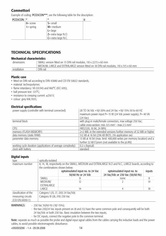
ConnettoriExample of coding: PCO3CON***, see the following table for the description:
PCO3CON * * 00= screw1= spring
S= smallM= mediumL= largeZ= extra large N.O.C= extra large N.C.
TECHNICAL SPECIFICATIONS
Mechanical characteristicsdimensions SMALL version fi tted on 13 DIN rail modules, 110 x 227.5 x 60 mm
MEDIUM, LARGE and EXTRALARGE version fi tted on 18 DIN rail modules, 110 x 315 x 60 mminstallation DIN rail
Plastic case• fi tted on DIN rail according to DIN 43880 and CEI EN 50022 standards;• material: technopolymer;• fl ame retardancy: V0 (UL94) and 960°C (IEC 695);• ball pressure test: 125°C;• resistance to creeping current: ≥250 V;• colour: grey RAL7035;
Electrical specifi cationspower supply (controller with terminal connected) 28 TO 36 Vdc +10/-20% and 24 Vac +10/-15% 50 to 60 HZ
maximum power input P= 15 W (24 Vdc power supply), P= 40 VA (24 Vac)
terminal block with plug-in male/female connectors, max voltage 250 Vac; cable cross-section: min. 0.5 mm2 - max 2.5 mm2
CPU H8S2320, 16 bit, 24 MHzmemory (FLASH MEMORY) 2+2 MB; in the extended versions further memory of 32 MB or higherdata memory (static RAM) 512 kB at 16 bit (296 kB BIOS; 216 application sw)parameter data memory 13 kB at 16 bit (max. limit: 400,000 writes per memory location) and a
further 32 kB E2prom (not available to the pLAN)working cycle duration (applications of average complexity) 0.2 s (typical)clock with battery standard
Digital inputs type optically-isolatedmaximum number 8, 14, 18, respectively on the SMALL, MEDIUM and EXTRALARGE N.O and N.C., LARGE boards, according to
the combinations shown below:optoinsulated input no. to 24 Vac
50/60 Hz or 24 Vdcoptoinsulated input no. to
24 Vac/Vdc or 230 Vac (50/60 Hz)inputs
SMALL 8 none 8MEDIUM/EXTRALARGE
12 2 14
LARGE 14 4 18classifi cation of the measuring circuits (CEI EN 61010-1)
Category I (J5, J7, J20) 24 Vac/VdcCategory III (J8, J19) 230 Vac
WARNINGS: - 230 Vac 50/60 Hz (10/-15%); - the two 230/24 Vac inputs present on J8 and J12 have the same common pole and consequently will be both 24 Vac/Vdc or both 230 Vac. Basic insulation between the two inputs; - for DC inputs, connect the negative pole to the common terminal.Note: separate as much as possible the probe and digital input signal cables from the cables carrying the inductive loads and the power cables, to avoid possible electromagnetic disturbance.

15+050003290 - 1.4 - 29.09.2006
Analogue inputs analogue conversion 10 bit A/D converter in the CPUtype universal: (inputs B1, B2, B3, B6, B7, B8) CAREL NTC temperature sensor (-50T90°C; R/T 10 kΩ at 25°C),
HT NTC 0T150°C, voltage: 0 to 1 Vdc, 0 to 5 V ratiometric or 0 to 10 Vdc, current: 0 to 20 mA or 4 to 20 mA, selectable via software. Input resistance in 0 to 20 mA= 100Ωpassive: (inputs B4, B5, B9, B10) CAREL NTC temp. sensor (see universal type), PT1000 (-100T200°C; R/T 1000 Ω at 0°C) or voltage-free digital input (5 mA), selectable via software;
maximum number 5, 8, 10, on the SMALL, MEDIUM and EXTRALARGE N.O., LARGE and EXTRALARGE N.C. boards respectivelytime constant for each input 0.5 sprecision ± 0.3 % of full scaleclassifi cation of the measuring circuits (CEI EN 61010-1)
Category I
WARNING: the 21 Vdc available at the +Vdc terminal (J2) can be used to power any active probes, the maximum current is 150 mA, thermally protected against short-circuits. To supply the ratiometric 0 to 5 V probes, use the +5VREF (Imax: 60 mA) present at terminal J24.
Analogue outputs type 0 to 10 Vdc optically-isolatedmaximum number 4, 4, 6, on the SMALL, MEDIUM and EXTRALARGE N.O./N.C., LARGE boards respectivelypower supply external 24 Vac/Vdcresolution 8 bitmaximum load 1 kΩ (10 mA)precision ± 2 % of end scale on outputs: Y1, Y2, Y3 and Y4
-2%/+5% of end scale on: Y5 and Y6
Digital outputstype relaymaximum number 8: SMALL; 13: MEDIUM; 18: LARGE; 27: EXTRALARGE N.C.; 29: EXTRALARGE N.O.
For the requirements refer to Figs. 3 to 5 (reference NO*, NC* and C*). Note the presence of outputs with changeover contacts kept separately (that is, without the poles shared between different outputs). Groups from 2 to 5 outputs have 2 “common” poles for easy assembly.Make sure that the current running through the common terminals does not exceed the rated current of each individual terminal, that is 8A.
Insulation distance the outputs can be divided into groups. There is double insulation between groups (between cells in the table).Note: the relays in the same group must have the same power supply (24 or 230 Vac).
Makeup of the groups version relays with same insulationSMALLType of relay
1…7 8 - - -A type A type
MEDIUMType of relay
1…7 8 9…13 - -A type A type A type
LARGEType of relay
1…7 8 9…13 14…18 -A type A type A type A type
EXTRALARGE N.O.Type of relay
1…7 8 9…13 14…16 17…20 21…24 25…29A type A type A type B type B type B type B type
EXTRALARGE N.C. 1…7 8 9…13 14…16 17…20 21…24 25…27Type of relay A type A type A type C type C type C type C type
Note: the relays in the individual cells of the table have basic insulation between them, while between groups (cell-cell) there is double insulation.
Changeover contacts 1: SMALL (relè 8); 3: MEDIUM e EXTRALARGE N.O./N.C. (relè 8, 12 e 13); 5: LARGE (relè 8, 12, 13, 14 e 15)Switchable power warning: the relay outputs have different characteristics according to the model of pCO3
relay type A
type of relay: SPDT, 2000 VA, 250 Vac, 8 A resistivepCO3 approval: UL873: 2.5 A resistive, 2 A FLA, 12 A LRA, 250 Vac, C300 pilot duty (30000 cycles) EN 60730-1: 2 A resistive, 2 A inductive, cosϕ= 0.6, 2(2) A (100000 cycles)
relay type B
type of relay: SPDT, 1250 VA, 250 Vac, 5 A resistive pCO3 approval: UL873: 1 A resistive, 1 A FLA, 6 A LRA, 250 Vac, D300 pilot duty (30000 cycles) EN 60730-1: 1 A resistive, 1 A inductive, cosϕ= 0.6, 1(1) A (100000 cycles)
relay type C
type of relay: SPDT, 1250 VA, 250 Vac, 5 A resistive pCO3 approval: UL873: 1 A resistive, 1 A FLA, 6 A LRA, 250 Vac, D300 pilot duty (30000 cycles) EN 60730-1: 1 A resistive, 1 A inductive, cosϕ= 0.6, 1(1) A (100000 cycles)
SSR outputs 1: SMALL (output 7); 2: MEDIUM - EXTRALARGE N.O./N.C. (outputs 7, 12); 3: LARGE (OUTPUTS 7, 12, 14)operating voltage 24 Vac/Vdc; maximum power: 10 W
english

16+050003290 - 1.4 - 29.09.2006
Relation between AWG and wire cross-sectionAWG Cross-section (mm2) Current20 0.5 215 1.5 614 2.5 8
pLAN network/user terminal connectiontype RS485 half-duplex asynchronoustransmission speed 62.5 Kbps or 115.2 Kbps, selectable via softwareterminal connector 6 pin telephone (J10)pLAN network/graphic terminal/aria terminal connector 3 pin plug-in connector (J11)
The maximum distance between the pCO and user terminal is shown in the following table.cable type power supply distance power supplytelephone 50 m taken from the pCO (150 mA)AWG24 shielded cable 200 m taken from the pCO (150 mA)AWG20/22 shielded cable 500 m separate power supply via TCONN6J000
The maximum distance between two pCO3 controllers with AWG20/22 shielded cable is 500 m.Note:• a maximum of one terminal (pCOT, pCOI, pGD0, pGD1) can be connected, or two terminals but without using use the backlighting on display. One version of the pCO3 features optically-isolated connection to the pLAN network.• the graphic terminal and aria terminal should be always powered with a separate power supply.• the 21 Vdc present at +Vterm (J24) can be used to power an external terminal with a maximum input of 2 W. Only one terminal can be connected (for example PLD terminal or ARIA terminal) in addition to the one connected to terminal J10.
Other specifi cationsstorage conditions -40T70 °C, 90% RH non-condensingoperating conditions -25T70 °C, 90% RH non-condensingindex of protection IP20, IP40 front panel onlyenvironmental pollution normalclass according to protection against electric shock to be incorporated into Class I and/or II appliancesPTI of the insulating materials 250 Vperiod of stress across the insulating parts longtype of action 1Ctype of disconnection or microswitching microswitchingcategory of resistance to heat and fi re category D (UL94 - V0)immunity against voltage surges category 1ageing characteristics (operating hours) 80,000no. of automatic operating cycles 100,000 (EN 60730-1); 30,000 (UL 873)software class and structure Class Acategory of immunity to voltage surges (CEI EN 61000-4-5) Category IIIThe device is not designed to be hand-held
WARNING• for applications subject to strong vibrations (1.5 mm pk-pk 10/55 Hz), secure the cables connected to the µ pCO3 using clamps placed around 3 cm from the connectors • If the product is installed in industrial environments (application of the EN 61000-6-2 standard) the length of the output connections must be less than 30 m.• installation must be performed according to the standards and legislation in force in the country where the appliance is used;• for safety reasons the appliance must be housed inside an electrical panel, so that the only accessible part is the display and the control keypad;• all the very low voltage connections (analogue and digital inputs at 24 Vac/Vdc, analogue outputs, serial bus connections, power) must have reinforced or double insulation from the mains;• in the event of malfunctions do not attempt to repair the appliance, but rather contact the CAREL service centre;• in domestic environments, the connection cable between the pCO3 and the terminal must be shielded.

17+050003290 - 1.4 - 29.09.2006
DIMENSIONSDimensions pCO3 MEDIUM, LARGE, EXTRALARGE N.O. and N.C.
11045
315 60
44
Fig. 4
Dimensions pCO3 SMALL
227,5
11045
60
44
Fig. 5
PRODUCT CERTIFICATIONCEI EN 50155 standard: “Railway applications − Electronic equipment used on rolling stock”;UL 873 and C22.2 No. 24-93: “Temperature-Indicating and -Regulating Equipment”;EC regulations 37/2005 of 12 January 2005; in particular, if the electronic controller is fi tted with standard Carel NTC probes, it is compliant with standard EN13485 on “Thermometers for measuring the air temperature in applications on units for the conservation and sale of refrigerated, frozen and deep-frozen food and ice cream”.
Disposal of the productThe appliance (or the product) must be disposed of separately in accordance with the local waste disposal legislation in force.
•••
english

18+050003290 - 1.4 - 29.09.2006
INSTRUMENT ELEMENTS
service
card
Rx-/Tx-
Rx+/Tx+
GND
C1
NO1
NO2
NO3
C1
C4
NO4
NO5
NO6
C4
C7
NO7
C7
NO8
C8
NC8
NO12
C12
NC12
NO13
C13
NC13
C9
NO9
NO10
NO11
C9
G
G0
B1
B2
B3
GND
+VDC
+Vterm
GND
+5 VREF
B4
BC4
B5
BC5
VG
VG0
Y1
Y2
Y3
Y4
ID1
ID2
ID3
ID4
ID5
ID6
ID7
ID8
IDC1
B6
B7
B8
GND
ID9
ID10
ID11
ID12
IDC9
ID13H
ID13
IDC13
ID14
ID14H
J1
10
1
11
J24J2
J3J4
J5J7
J8
J20
J21
J14J11
J10J9
J13J12
J22
J16J17
J18J15
J23
J6
J19
3
7
7
4
4
6
5
NO14
C14
NC14
NO15
C15
NC15
C16
NO16
NO17
NO18
C16
E-
E+
GND8
9
2
13
ID15H
ID15
IDC15
ID16
ID16H
Y5
Y6
ID17
ID18
IDC17
B9
BC9
B10
BC10
16
15
14fie
ld card
serial card
8
6
5
7
12
11
17
input: 24 V / ; 50 to 60 Hzm
ax. power: 40 VA/15W
Fig. 3

19+050003290 - 1.4 - 29.09.2006
EXTRALARGE N.O. version
J20
J21J22
J23
J19
C14
NO14
NO15
NO16
C14
C17
NO17
NO18
NO19
NO20
C17
E-
E+
GND
C25
NO25
NO26
NO27
NO28
NO29
C25
C21
NO21
NO22
NO23
NO24
C21
1211
Fig. 4
EXTRALARGE N.C. version
J20J25
J21J22
J23
J19
C14
NC14
NC15
NC16
C14
C17
NC17
NC18
NC19
NC20
C17
E-
E+
GNDB9
B10
BC9
C25
NC25
NC26
NC27
C25
C21
NC21
NC22
NC23
NC24
C21
512
11
Fig. 5
Key (Figs. 3 to 5)1. power supply connector [G (+), G0 (-)];2. yellow power LED and 3 LEDs for the pLAN networks;3. additional power supply (max. 200 mA) for the
terminal and 0 to 5 V ratiometric probes;4. universal NTC, 0 to 1 V, 0 to 5 V ratiometric, 0 to 10 V,
0 to 20 mA, 4 to 20 mA analogue inputs;5. passive NTC, PT1000, ON/OFF analogue inputs;6. 0 to 10 V analogue outputs; 7. 24 Vac/Vdc digital inputs;8. 230 Vac or 24 Vac/Vdc digital inputs;9. connector for terminal display (external panel with
direct signals);10. connector for all the standard pCO series terminals
and for downloading the application software;11. digital relay outputs;12. connector for the I/O board expansion;13. pLAN connector;14. cover for inserting the optional supervisor serial board;15. cover for inserting the optional fi eld board;16. cover for inserting the optional service board;17. Built-In terminal (LCD, buttons and LEDs).
english

20+050003290 - 1.4 - 29.09.2006
PRELIMINARY NOTES FOR THE INSTALLER: COMPARISON BETWEEN pCO3 AND pCO2
• the pCO3 family controllers do not have the connector using the programming key code PCO201KEY0. To program the controller, use the new Smart Key (PCOS00AKY0) available from September 2005. Otherwise use WinLoad ver. 3.35 and higher:
Fig. 6 An application cannot be run from the Smart Key;• unlike the pCO2, there is no fuse between J1 and J2. All pCO3 family controllers have an internal thermal protector on the power supply. No external fuse is required;• a further terminal J24 (in place of the fuse) is provided for the power supply to the ratiometric probes (+5 VREF), as well as 20 Vdc to supply a secondary terminal, such as the aria terminal (TAT***), in alternative to the standard one;• the terminal J11 (connection to the pLAN network) in the fi rst prototypes of the pCO3 only has a pitch of 3.81, rather than the 5.08 on the pCO2;• the LEDs near the dipswitches for setting the pLAN address have been moved between connectors J3 and J4;• the red probe power supply overload LED has been removed.
pCO3 simulator:If testing the pCO3 with a simulator, note that the pCO2 simulator cannot be used in place of the pCO3 simulator. Contact CAREL for the availability of the latter.
Procedure for setting the address of the controller and terminal
Setting the address of the controllerThe pCO3 controller does NOT have dipswitches for setting the pLAN address. The address must be set by software, as for the pCO1/XS.
The procedure is as follows:1. switch the pCO3 off;2. prepare a standard Carel terminal with the address set to 0 (not necessary if the pCO3 Built-In terminal is used). For this operation, see the following paragraph;3. connect the terminal to the pCO3;4. disconnect any other devices connected in the pLAN from the pCO3 (terminal J11);5. switch the pCO3 on, pressing the UP + ALARM buttons at the same time. This combination of buttons is the same on the built in
terminal. Alternatively, on the PCOT terminals, use the combination of the menu and buttons.6. after a few seconds, the following screen will be displayed:
PLAN ADDRESS: 0UP: INCREASEDOWN: DECREASEENTER: SAVE & EXIT
7. to modify the address simply use the UP and DOWN buttons and then press ENTER to confi rm.8. now set the pLAN address of the terminal and confi gure the pLAN network.
Setting the address of the terminal pCOI/pCOT terminalThe address of the terminal is set using the DIPSWITCHES on the rear of the terminal.
pGD0/1/2/3 terminalThe default value of the address is 32.The address of the terminal can only be set after having connected the power supply via the telephone connector.To enter confi guration mode, press the ↓↑↵ buttons at the same time (even when the terminal is already on), in all the versions, for at least 5 seconds; the following screen will be displayed, with the cursor fl ashing in the top left corner:
Display addresssetting.........:nn
I/O Board address:xx
• to modify the address of the terminal (display address setting) press the ↵ button once: the cursor will move to the address fi eld (nn).
21+050003290 - 1.4 - 29.09.2006
• use the ↓↑ buttons to select the desired value, and confi rm by pressing the ↵ button. If the value selected is different than the value saved previously, the screen shown below will be displayed, and the new value will be saved to permanent memory.
Display addresschanged
If the fi eld nn is set to the value 0, the terminal will communicate with the pCO3 controller using the “point-to-point” protocol (not pLAN) and the “I/O Board address: xx” fi eld will not be displayed, as it no longer has meaning.
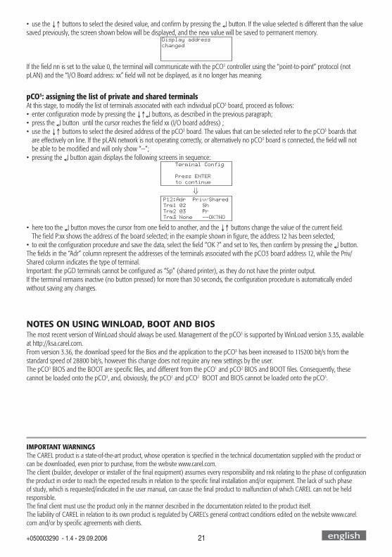
pCO3: assigning the list of private and shared terminalsAt this stage, to modify the list of terminals associated with each individual pCO3 board, proceed as follows:• enter confi guration mode by pressing the ↓↑↵ buttons, as described in the previous paragraph;• press the ↵ button until the cursor reaches the fi eld xx (I/O board address) ;• use the ↓↑ buttons to select the desired address of the pCO3 board. The values that can be selected refer to the pCO3 boards that are effectively on line. If the pLAN network is not operating correctly, or alternatively no pCO3 board is connected, the fi eld will not be able to be modifi ed and will only show “—”;• pressing the ↵ button again displays the following screens in sequence:
Terminal Config
Press ENTERto continue
P12:Adr Priv/SharedTrm1 02 ShTrm2 03 PrTrm3 None --OK?NO
• here too the ↵ button moves the cursor from one fi eld to another, and the ↓↑ buttons change the value of the current fi eld. The fi eld P:xx shows the address of the board selected; in the example shown in fi gure, the address 12 has been selected;• to exit the confi guration procedure and save the data, select the fi eld “OK ?” and set to Yes, then confi rm by pressing the ↵ button.The fi elds in the “Adr” column represent the addresses of the terminals associated with the pCO3 board address 12, while the Priv/Shared column indicates the type of terminal.Important: the pGD terminals cannot be confi gured as “Sp” (shared printer), as they do not have the printer output.If the terminal remains inactive (no button pressed) for more than 30 seconds, the confi guration procedure is automatically ended without saving any changes.
NOTES ON USING WINLOAD, BOOT AND BIOSThe most recent version of WinLoad should always be used. Management of the pCO3 is supported by WinLoad version 3.35, available at http://ksa.carel.com.From version 3.36, the download speed for the Bios and the application to the pCO3 has been increased to 115200 bit/s from the standard speed of 28800 bit/s, however this change does not require any new settings by the user.The pCO3 BIOS and the BOOT are specifi c fi les, and different from the pCO1 and pCO2 BIOS and BOOT fi les. Consequently, these cannot be loaded onto the pCO3, and, obviously, the pCO1 and pCO2 BOOT and BIOS cannot be loaded onto the pCO3.
IMPORTANT WARNINGSThe CAREL product is a state-of-the-art product, whose operation is specifi ed in the technical documentation supplied with the product or can be downloaded, even prior to purchase, from the website www.carel.com.The client (builder, developer or installer of the fi nal equipment) assumes every responsibility and risk relating to the phase of confi guration the product in order to reach the expected results in relation to the specifi c fi nal installation and/or equipment. The lack of such phase of study, which is requested/indicated in the user manual, can cause the fi nal product to malfunction of which CAREL can not be held responsible.The fi nal client must use the product only in the manner described in the documentation related to the product itself. The liability of CAREL in relation to its own product is regulated by CAREL’s general contract conditions edited on the website www.carel.com and/or by specifi c agreements with clients.
english

42+050003290 - 1.4 - 29.09.2006
G G0
230/
24 V
ac
M
OU
T
+V
anal
og o
utpu
t 1 (
0/10
Vdc
)
anal
og o
utpu
t 2 (
0/10
Vdc
)
anal
og o
utpu
t 3 (
0/10
Vdc
)
anal
og o
utpu
t 4 (
0/10
Vdc
)
L N
digi
tal o
utpu
t 1
digi
tal o
utpu
t 2
digi
tal o
utpu
t 3
digi
tal o
utpu
t 4
digi
tal i
nput
1
digi
tal i
nput
2
digi
tal i
nput
3
digi
tal i
nput
4
digi
tal i
nput
5di
gita
l inp
ut 6
digi
tal i
nput
7
digi
tal i
nput
8
digi
tal o
utpu
t 5di
gita
l out
put 6
digi
tal o
utpu
t 7
digi
tal o
utpu
t 8
prob
e 1
(0/5
V)
prob
e 2
(4/2
0 m
A)
prob
e 3
(0/1
Vdc
or 4
/20
mA)
prob
e 4
Car
el N
TC
prob
e 5
PT10
00
serv ice card
Rx-/T
x-
Rx+/
Tx+
GN
D
C1 NO
1
NO
2
NO
3
C1 C4 NO
4
NO
5
NO
6
C4 C7 NO
7
C7 NO
8
C8 NC8
G G0 B1 B2 B3
GN
D
+VDC
+Vte
rm
GN
D
+5 V
REF B4 BC4 B5 BC5 VG VG0 Y1 Y2 Y3 Y4 ID1
ID2
ID3
ID4
ID5
ID6
ID7
ID8
IDC1
J1 J24 J2 J3
J10J9
f ie ld card ser ia l cardinput: 24 V / ; 50 to 60 Hzmax. power: 40 VA/15W
SMALL
EXAMPLE GENERAL DIAGRAM OF THE ELECTRICAL CONNECTIONS

43+050003290 - 1.4 - 29.09.2006
NO
14 C14
NC1
4
NO
15 C15
NC1
5
C16
NO
16
NO
17
NO
18 C16 E- E+
GN
D
ID15
H
ID15
IDC1
5
ID16
ID16
H
Y5 Y6 ID17
ID18
IDC1
7
B9 BC9
B10
BC10
anal
og o
utpu
t 5 (
0/10
Vdc
)
digi
tal i
nput
15
digi
tal i
nput
16
digi
tal i
nput
17
digi
tal i
nput
18
digi
tal o
utpu
t 14
digi
tal o
utpu
t 15
digi
tal o
utpu
t 16
digi
tal o
utpu
t 17
digi
tal o
utpu
t 18
prob
e 9
CAR
EL N
TC
prob
e 10
volta
ge-fr
eedi
gita
l inp
ut
anal
og o
utpu
t 6 (
0/10
Vdc
)
out H M
NT
CN
TC
+ (
G)
digi
tal i
nput
9
CP digi
tal i
nput
10
digi
tal i
nput
11
digi
tal i
nput
12
digi
tal i
nput
13
digi
tal i
nput
14
digi
tal o
utpu
t 9
digi
tal o
utpu
t 10
digi
tal o
utpu
t 11
digi
tal o
utpu
t 12
digi
tal o
utpu
t 13
prob
e 8
CAR
EL N
TC
prob
e 6
- 7N
O12
C12
NC1
2
NO
13
C13
NC1
3
C9 NO
9
NO
10
NO
11
C9
B6 B7 B8
GN
D
ID9
ID10
ID11
ID12
IDC9
ID13
H
ID13
IDC1
3
ID14
ID14
H
MEDIUM LARGE

CAREL S.p.A.Via dell’Industria, 11 - 35020 Brugine - Padova (Italy)Tel. (+39) 049.9716611 - Fax (+39) 049.9716600e-mail: [email protected] - www.CAREL.com
Agenzia / Agency:
+050
0032
90 -
1.4
- 28
.09.
2006