Embed Size (px)
Citation preview
Fokker 70 lost all braking pressure during taxi-in Ground-flight detection failure resulting in collision
DUTCHSAFETY BOARD
The Hague, December 2019
The reports issued by the Dutch Safety Board are open to the public.
All reports are also available on the Safety Board’s website www.safetyboard.nl
Photo cover: Aviation police.
Fokker 70 lost all braking pressure during taxi-in Ground-flight detection failure resulting in collision
- 3 -
The Dutch Safety Board
When accidents or disasters happen, the Dutch Safety Board investigates how it was possible for these to occur, with the aim of learning lessons for the future and, ultimately, improving safety in the Netherlands. The Safety Board is independent and is free to decide which incidents to investigate. In particular, it focuses on situations in which people’s personal safety is dependent on third parties, such as the government or companies. In certain cases the Board is under an obligation to carry out an investigation. Its investigations do not address issues of blame or liability.
Dutch Safety BoardChairman: J.R.V.A. Dijsselbloem
M.B.A. van AsseltS. Zouridis
Secretary Director: C.A.J.F. Verheij
Visiting address: Lange Voorhout 92514 EA The HagueThe Netherlands
Postal address: PO Box 954042509 CK The HagueThe Netherlands
Telephone: +31 (0)70 333 7000
Website: safetyboard.nlE-mail: [email protected]
N.B. This report is published in the English language with a separate Dutch summary. If there is a difference in interpretation between the report and the summary, the report text will prevail.
- 4 -
CONTENT
General information ................................................................................................... 5
Summary .................................................................................................................... 6
Abbreviations ............................................................................................................. 8
1 Factual information ..............................................................................................101.1 History of flight ..................................................................................................... 101.2 Personnel information .......................................................................................... 131.3 Aircraft information .............................................................................................. 141.4 Flight data and cockpit voice recorder ................................................................ 141.5 Aircraft systems and continued airworthiness ..................................................... 151.6 Troubleshooting after the event ........................................................................... 191.7 Aircraft maintenance and PSEU 207 repair history ............................................... 201.8 Investigation ground-flight associated units and components ............................ 231.9 Investigation electromagnetic interference.......................................................... 261.10 Electrical power switching and ground-flight ....................................................... 281.11 Other occurrences ................................................................................................ 28
2 Analysis ............................................................................................................... 302.1 Loss of control and risks ....................................................................................... 302.2 Ground to flight switching and braking during taxi ............................................. 302.3 Analysing ground-flight control on aircraft system level ...................................... 322.4 Analysing ground-flight control on component level ........................................... 342.5 Reviewing PSEU 207 history ................................................................................. 362.6 Other possible factors affecting ground-flight switching .................................... 372.7 Risk of ground-flight detection failures ................................................................ 38
3 Conclusions ......................................................................................................... 40
Appendix A. F70 braking system ...........................................................................41
Appendix B. Ground-flight control ........................................................................ 42
Appendix C. QAR data .......................................................................................... 43
Appendix D. Limitations of investigation .............................................................. 46
- 5 -
GENERAL INFORMATION
Reference number LV2015017
Classification Serious incident
Date of occurrence 5 March 2015
Time of occurrence 12.03 hours UTC
Location of occurrence Amsterdam Schiphol Airport, the Netherlands
Aircraft registration PH-WXC
Aircraft model Fokker F28 Mk 0070 (Fokker 70)
Aircraft type Two turbofan engines jet aircraft
Flight type Scheduled passenger flight
Flight phase Taxi-in
Damage to aircraft Minor
Number of crew members 2 flight crew, 2 cabin crew
Number of passengers 36
Injuries None
Other damage GPU
Light conditions Daylight
- 6 -
SUMMARY
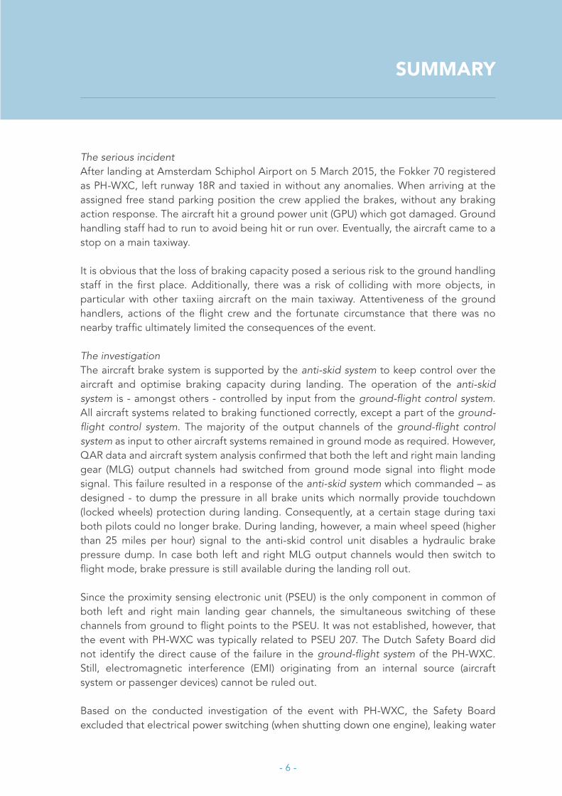
The serious incidentAfter landing at Amsterdam Schiphol Airport on 5 March 2015, the Fokker 70 registered as PH-WXC, left runway 18R and taxied in without any anomalies. When arriving at the assigned free stand parking position the crew applied the brakes, without any braking action response. The aircraft hit a ground power unit (GPU) which got damaged. Ground handling staff had to run to avoid being hit or run over. Eventually, the aircraft came to a stop on a main taxiway.
It is obvious that the loss of braking capacity posed a serious risk to the ground handling staff in the first place. Additionally, there was a risk of colliding with more objects, in particular with other taxiing aircraft on the main taxiway. Attentiveness of the ground handlers, actions of the flight crew and the fortunate circumstance that there was no nearby traffic ultimately limited the consequences of the event.
The investigationThe aircraft brake system is supported by the anti-skid system to keep control over the aircraft and optimise braking capacity during landing. The operation of the anti-skid system is - amongst others - controlled by input from the ground-flight control system. All aircraft systems related to braking functioned correctly, except a part of the ground-flight control system. The majority of the output channels of the ground-flight control system as input to other aircraft systems remained in ground mode as required. However, QAR data and aircraft system analysis confirmed that both the left and right main landing gear (MLG) output channels had switched from ground mode signal into flight mode signal. This failure resulted in a response of the anti-skid system which commanded – as designed - to dump the pressure in all brake units which normally provide touchdown (locked wheels) protection during landing. Consequently, at a certain stage during taxi both pilots could no longer brake. During landing, however, a main wheel speed (higher than 25 miles per hour) signal to the anti-skid control unit disables a hydraulic brake pressure dump. In case both left and right MLG output channels would then switch to flight mode, brake pressure is still available during the landing roll out.
Since the proximity sensing electronic unit (PSEU) is the only component in common of both left and right main landing gear channels, the simultaneous switching of these channels from ground to flight points to the PSEU. It was not established, however, that the event with PH-WXC was typically related to PSEU 207. The Dutch Safety Board did not identify the direct cause of the failure in the ground-flight system of the PH-WXC. Still, electromagnetic interference (EMI) originating from an internal source (aircraft system or passenger devices) cannot be ruled out.
Based on the conducted investigation of the event with PH-WXC, the Safety Board excluded that electrical power switching (when shutting down one engine), leaking water
- 7 -
into avionics equipment and EMI from airport power cables (external source) caused ground to flight switching.
Maintenance processesHaving reviewed the history of shop visits of the PSEU 207 and the event with the PH-WXC, it appeared that the involved maintenance organisation and overhaul & repair shops faced failures which were difficult to identify and to solve the cause(s).
History of shop visits of PSEU 207 showed that after unscheduled replacements during the maintenance and repair processes the failure(s) could often not be reproduced and no clear other indication of failure was found. Also the replacement of the PSEU, which was likely initiated in the troubleshooting phase, may not always be justified regarding the complaint. In a few cases some anomalies were found and repaired. On every occasion PSEU 207 passed the tests to regain airworthiness. Consequently, in line with the regulations the unit could be re-installed in any Fokker 70/100 aircraft. In view of the Dutch Safety Board, despite adherence to prescribed maintenance procedures and compliance with airworthiness requirements, it remained unclear what the shop visits had really solved.
After repair Line Replaceable Units (LRUs) like PSEU are usually re-used by different operators when they participate in a pool system. The pool system, for which no regulatory framework exists, is a warehouse for aircraft parts ready for use to replace parts which need to be repaired first. Once repaired a LRU is stored in the pool system and will usually be delivered to a different operator. As a consequence the individual operator could not keep track of the PSEU 207 history as outlined in the regulatory framework for operators. The procedures for maintenance and requirements for airworthiness were still met. In the industry these maintenance practises are rather common for avionics LRU’s and not just typical for PSEU’s. This situation has the potential for a safety risk.
Because no direct cause was identified no official recommendations were made. Still, the conclusions in this report bear lessons about safety related to PSEU and maintenance practises by better securing the effectivity of continued airworthiness.
- 8 -
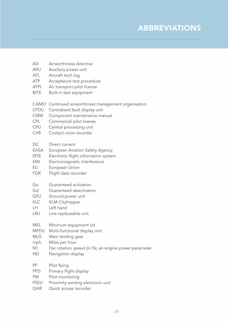
ABBREVIATIONS
AD Airworthiness directiveAPU Auxiliary power unitATL Aircraft tech logATP Acceptance test procedureATPL Air transport pilot licenseBITE Built-in test equipment
CAMO Continued airworthiness management organisationCFDU Centralised fault display unit CMM Component maintenance manualCPL Commercial pilot licenseCPU Central processing unit CVR Cockpit voice recorder
DC Direct currentEASA European Aviation Safety AgencyEFIS Electronic flight information systemEMI Electromagnetic interferenceEU European UnionFDR Flight data recorder
Ga Guaranteed activationGd Guaranteed deactivationGPU Ground power unitKLC KLM CityhopperLH Left handLRU Line replaceable unit
MEL Minimum equipment listMFDU Multi-functional display unit MLG Main landing gearmph Miles per hourN1 Fan rotation speed (in %), an engine power parameter ND Navigation display
PF Pilot flyingPFD Primary flight displayPM Pilot monitoringPSEU Proximity sensing electronic unitQAR Quick access recorder

- 9 -
RH Right handRT Radio telephonyrpm Rounds per minutes/n Serial number SOP Standard operating procedure(s)WO Work orderWOW Weight on wheels

- 10 -
1 FACTUAL INFORMATION
1.1 History of flight
The Fokker 70 aircraft, registered as PH-WXC and operated by KLM Cityhopper (KLC), was to be flown by the captain in the left hand seat and the first officer in the right hand seat. In the cabin there were two cabin crew and 36 passengers. The flight was from Durham/Teesside in the United Kingdom to Amsterdam Schiphol in the Netherlands.
The crew started its duty in Durham/Teesside and took over the aircraft from the arriving crew. According to the first officer no subjects of importance were discussed with the arriving crew. It appeared that the navigation display (ND) on the captain’s side was unserviceable and this information was found in the minimum equipment list (MEL). Consequently, in contradiction to the original plan both pilots agreed that the first officer would be the pilot flying (PF) and the captain would be the pilot monitoring (PM).
The flight to Amsterdam Schiphol including the landing on runway 18R was uneventful. During the landing roll out the crew applied brakes and thrust reversers. Since runway 18R is a long runway and without having other landing traffic behind, limited braking action was required. The crew chose to leave the runway via the next runway exit. When vacating the runway the first officer requested the captain to shut down engine #2 in line with company policy to save fuel.
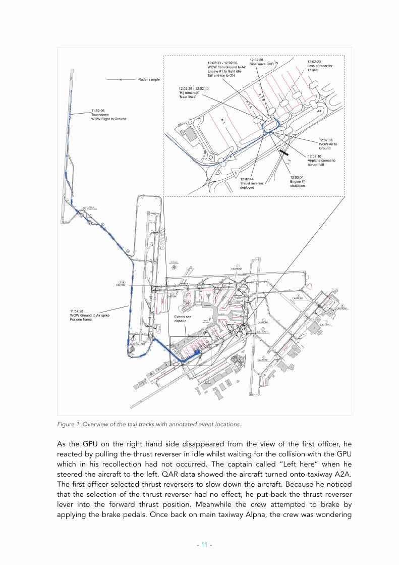
The crew taxied via taxiways Victor and Zulu via the south to Quebec to the assigned parking position B61, see Figure 1. The first officer explained that he occasionally applied the brakes without anomalies and the crew was in no rush since the flight was on time. Data from the quick access recorder (QAR) indicated that a ‘ground to flight’ spike occurred at 11:57:28 hours. At 12:02:33 hours engine power increased from 23% N1 (ground idle) to 33% (flight idle) without being noticed by the crew. When approaching the parking position the crew saw two ground handlers near the ground power unit (GPU) ready to connect the power cable of the GPU to the aircraft to supply external electrical power. The crew had not heard any warnings nor observed any messages on the multi-functional display system (MFDS).
When turning into the parking stand the first officer applied the brakes to slow down a little bit and experienced no response from the braking system. The first officer stated that he exclaimed to the captain “It does not brake!” whilst he had fully pushed down the brake pedals which itself felt normal. Then also the captain had fully applied the brakes without any effect on the aircraft. Only one ground handler looked at the aircraft and when he suddenly noticed it was coming towards them without slowing down, he warned his colleague who was facing the GPU and could not see the aircraft. The two ground handlers then fled into the direction of parking spot B62.
- 11 -
3453 x 45 m
E-PI
ER
A6
2014 x 45 m
3300
x 4
5 m
D-PIER
3500 x 45 m
C-PIE
R
3400
x 4
5 m
F-PIER
G-PIER
TERMINAL
FREIGHT
A12
E4E4
E5
G2
G5
G4
G4
G3
G2
G
G
G
E4
E3
E2E1
S 6
S5
S4
S3
S2
S1
S2
W8
W6
A21 A20 A19 A18 A17 A16 A15 A14 A13
A11
A9
A8
A5
A3
A2
A4
A3
A4W
A2DA2CA2BA2A
A1
N1
A5
A8
N5
A22
A
B
A19 A17
N4 N3N2N9
A16
A14
A13
A12
A10
A9C
A
B
B
A
W1
R
E6
G1
B-C orridor
B-PIER
A7
G
G
G5
09
27
24
22
06
04
1112
10
14
5
4
1
2
3
III
II
I
V
VI
VI
B
A
W7
A4E
2929
2929
40
36
52
5236
E5
A13
A6
52
31
31
A10
32
G-apron
D-apron
E-apron
J-ap
ron
H-apron
R-apron
S-apron
M-apron
P-holding
V2V1
V3
V4
3800
x 6
0 m
W3
W5
V
V
V
V
VK
VL
VM
A24
Z
W5
P4
P5
A26
A25Z
Y-ap
ron
NOT IN USE
V
ZZ1
Z2
AB
B A
B
A
A
B
C 1
C 2
C 3
H-PIE R
D C
C
C
Y
YY
Y
Y2 Y1
36HN
A19NA19S
W2
W4
W9
W10
W11
W12
E3
X
X
X
A27
X
X
XA20
A8
52
52
73
69
69
Q
69
K-ap ron
GD
G
69
69
6565 6565
65
65
65
X
X
80
69
GL1
CAUTION !
36C
36R
18C
18L
1CAUTION !
1CAUTION !
FIRE BRIGADEPRACTICE GROUND
18R
36L
TWR-W183 ft AMSL
TWR-C320 ft AMSL 1
CAUTION !
U5
U4
U3
U2
U1
U-a
pron
S7E
S
S
S8
2CAUTION !
6CAUTION !
4
5CAUTION !
5CAUTION !
3CAUTION !
S7W
S3
A3
A2A
2BA
2A
A1
A
B
11:57:28WOW Ground to Air spikeFor one frame
11:52:06TouchdownWOW Flight to Ground
x Radar sample
Events seecloseup
12:02:33 - 12:02:35WOW from Ground to AirEngine #1 to flight idleTail anti-ice to ON
12:02:20Loss of radar for17 sec.
12:02:39 - 12:02:40“Hij remt niet”“Naar links”
12:03:10Airplane comes toabrupt halt
12:02:28Sine wave CVR
12:02:44Thrust reverserdeployed
12:03:04Engine #1 shutdown
12:07:33WOW Air toGround
Figure 1: Overview of the taxi tracks with annotated event locations.
As the GPU on the right hand side disappeared from the view of the first officer, he reacted by pulling the thrust reverser in idle whilst waiting for the collision with the GPU which in his recollection had not occurred. The captain called “Left here” when he steered the aircraft to the left. QAR data showed the aircraft turned onto taxiway A2A. The first officer selected thrust reversers to slow down the aircraft. Because he noticed that the selection of the thrust reverser had no effect, he put back the thrust reverser lever into the forward thrust position. Meanwhile the crew attempted to brake by applying the brake pedals. Once back on main taxiway Alpha, the crew was wondering
- 12 -
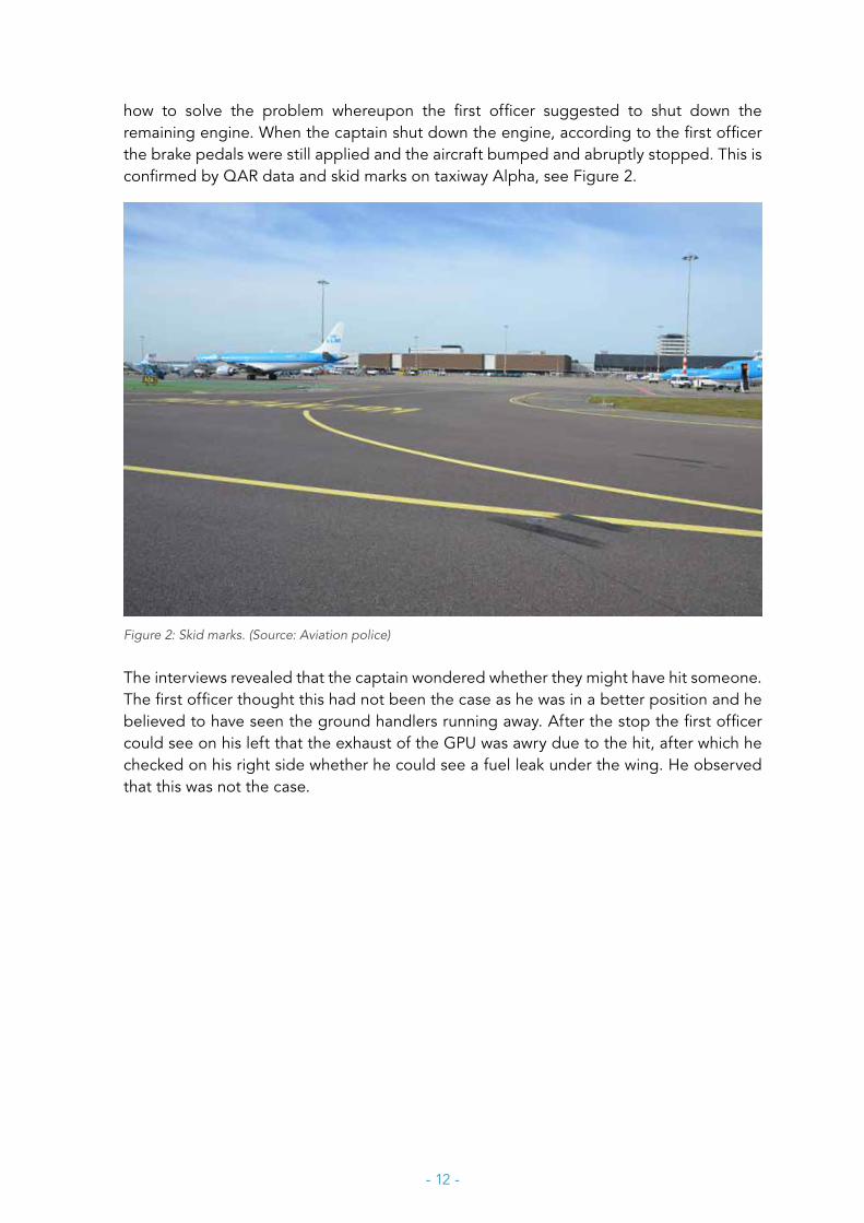
how to solve the problem whereupon the first officer suggested to shut down the remaining engine. When the captain shut down the engine, according to the first officer the brake pedals were still applied and the aircraft bumped and abruptly stopped. This is confirmed by QAR data and skid marks on taxiway Alpha, see Figure 2.
Figure 2: Skid marks. (Source: Aviation police)
The interviews revealed that the captain wondered whether they might have hit someone. The first officer thought this had not been the case as he was in a better position and he believed to have seen the ground handlers running away. After the stop the first officer could see on his left that the exhaust of the GPU was awry due to the hit, after which he checked on his right side whether he could see a fuel leak under the wing. He observed that this was not the case.
- 13 -
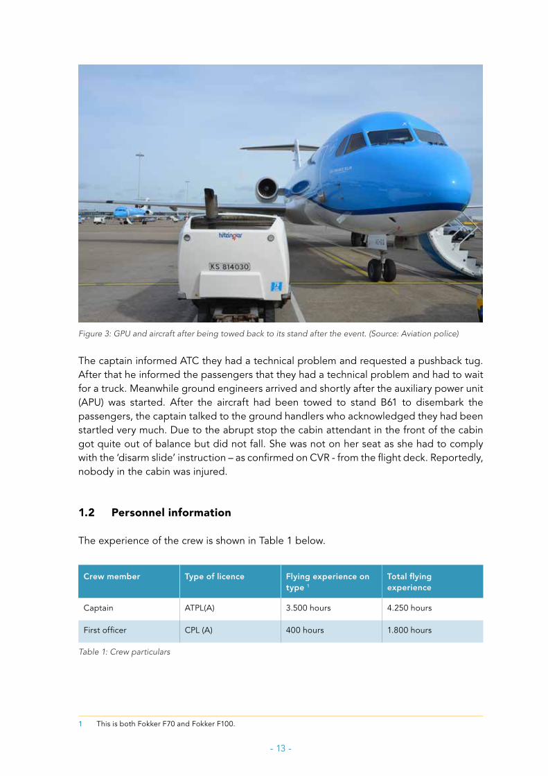
Figure 3: GPU and aircraft after being towed back to its stand after the event. (Source: Aviation police)
The captain informed ATC they had a technical problem and requested a pushback tug. After that he informed the passengers that they had a technical problem and had to wait for a truck. Meanwhile ground engineers arrived and shortly after the auxiliary power unit (APU) was started. After the aircraft had been towed to stand B61 to disembark the passengers, the captain talked to the ground handlers who acknowledged they had been startled very much. Due to the abrupt stop the cabin attendant in the front of the cabin got quite out of balance but did not fall. She was not on her seat as she had to comply with the ‘disarm slide’ instruction – as confirmed on CVR - from the flight deck. Reportedly, nobody in the cabin was injured.
1.2 Personnel information
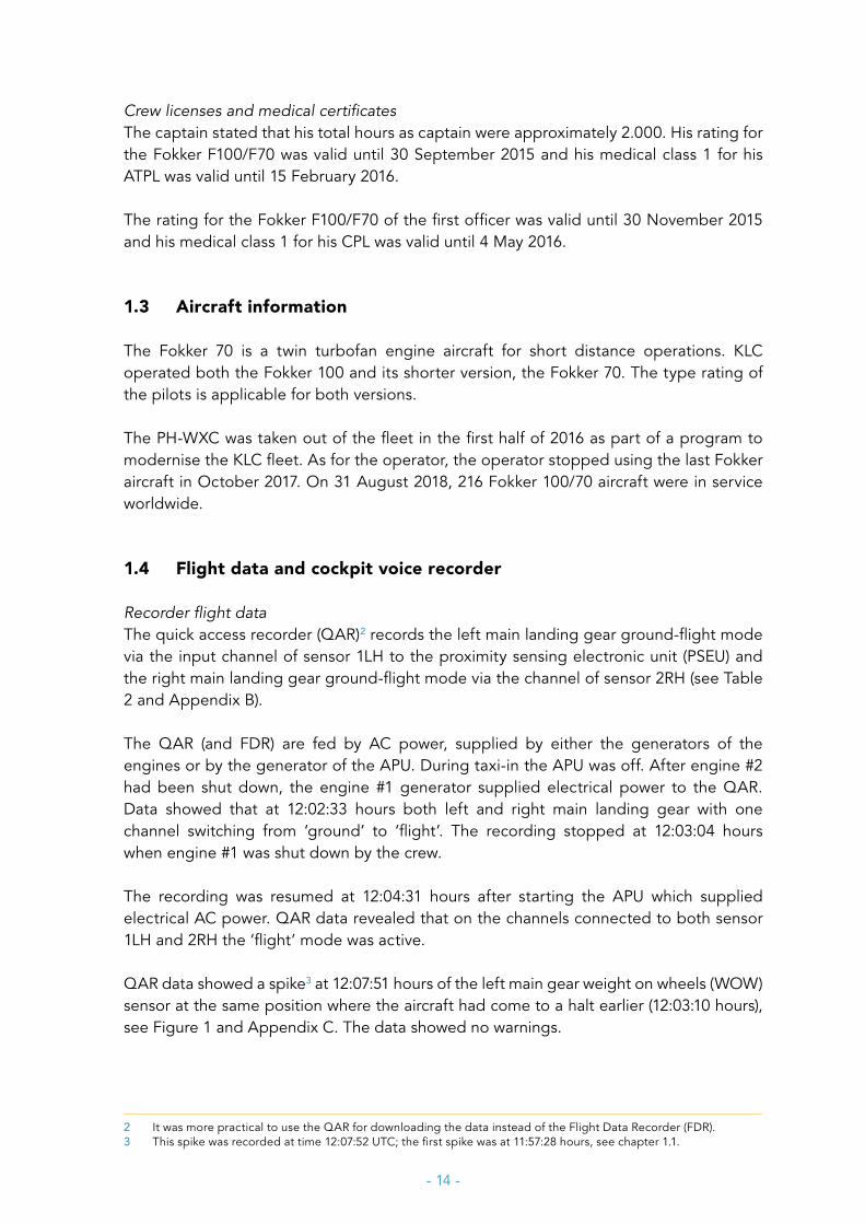
The experience of the crew is shown in Table 1 below.
Crew member Type of licence Flying experience on type 1
Total flying experience
Captain ATPL(A) 3.500 hours 4.250 hours
First officer CPL (A) 400 hours 1.800 hours
Table 1: Crew particulars
1 This is both Fokker F70 and Fokker F100.
- 14 -
Crew licenses and medical certificatesThe captain stated that his total hours as captain were approximately 2.000. His rating for the Fokker F100/F70 was valid until 30 September 2015 and his medical class 1 for his ATPL was valid until 15 February 2016.
The rating for the Fokker F100/F70 of the first officer was valid until 30 November 2015 and his medical class 1 for his CPL was valid until 4 May 2016.
1.3 Aircraft information
The Fokker 70 is a twin turbofan engine aircraft for short distance operations. KLC operated both the Fokker 100 and its shorter version, the Fokker 70. The type rating of the pilots is applicable for both versions.
The PH-WXC was taken out of the fleet in the first half of 2016 as part of a program to modernise the KLC fleet. As for the operator, the operator stopped using the last Fokker aircraft in October 2017. On 31 August 2018, 216 Fokker 100/70 aircraft were in service worldwide.
1.4 Flight data and cockpit voice recorder
Recorder flight dataThe quick access recorder (QAR)2 records the left main landing gear ground-flight mode via the input channel of sensor 1LH to the proximity sensing electronic unit (PSEU) and the right main landing gear ground-flight mode via the channel of sensor 2RH (see Table 2 and Appendix B).
The QAR (and FDR) are fed by AC power, supplied by either the generators of the engines or by the generator of the APU. During taxi-in the APU was off. After engine #2 had been shut down, the engine #1 generator supplied electrical power to the QAR. Data showed that at 12:02:33 hours both left and right main landing gear with one channel switching from ‘ground’ to ‘flight’. The recording stopped at 12:03:04 hours when engine #1 was shut down by the crew.
The recording was resumed at 12:04:31 hours after starting the APU which supplied electrical AC power. QAR data revealed that on the channels connected to both sensor 1LH and 2RH the ‘flight’ mode was active.
QAR data showed a spike3 at 12:07:51 hours of the left main gear weight on wheels (WOW) sensor at the same position where the aircraft had come to a halt earlier (12:03:10 hours), see Figure 1 and Appendix C. The data showed no warnings.
2 It was more practical to use the QAR for downloading the data instead of the Flight Data Recorder (FDR).3 This spike was recorded at time 12:07:52 UTC; the first spike was at 11:57:28 hours, see chapter 1.1.

- 15 -
GND/FLT1 left GND/FLT3 left GND/FLT2 right GND/FLT3 right logic
FDR X X
Table 2: Input signals to the QAR and FDR.
Cockpit voice recorder (CVR)The power supply of the cockpit voice recorder is similar to the power supply of the QAR (and FDR). The CVR recording of the flight was of good quality and included the event. CVR recording stopped when the remaining engine was shut down and it was resumed when the auxiliary power unit (APU) started running.
The CVR provided a sine wave with high damping factor which coincided with the start of a 17 second lasting disappearance of the position on the ground radar. The CVR recording was analysed by the investigation team and a Fokker test pilot. The origin and nature of the sine wave could not be identified. It was not believed to be normal aural sound.
1.5 Aircraft systems and continued airworthiness
Brake system and anti-skid systemThe Fokker 70/100 has two braking systems: the normal brake system and the alternate brake system. The normal brake system is used when hydraulic system 2 is available. The alternate brake system is pressurised by hydraulic system 1. When the pressure in hydraulic system 2 drops below a certain pre-set value, the alternate brake system will automatically take over. Shutting down one engine has no effect on the hydraulic systems. Each engine has two engine driven pumps: one to pressurise hydraulic system 1 and one to pressurise hydraulic system 2.
The anti-skid system automatically decreases the applied brake pressure when it detects a near skid on one or more of the main wheels. It works both during normal brake system operation and alternate brake system operation. The functionality of the brake system and the anti-skid system is shown in the schematic in Appendix A.
To prevent locked wheels during landing (touch down), should the pilot unintentionally apply the brake pedals, the anti-skid control box dumps the pressure allowing the wheels to spin up after landing. The anti-skid control box allows for braking pressure maximum 7 seconds after touch down, or as soon as sufficient wheel speed (25 miles per hour or more) is detected.
The ground-flight control system has four sensors – two on each main gear - with input channels to the proximity sensing electronic unit (PSEU). Two channels (one tied to sensor (1LH) on the left MLG and one sensor (2RH) on the right MLG) provide the PSEU with ground-flight input signals. The PSEU Logic Driver CCA’s 1 & 2 output channels provide
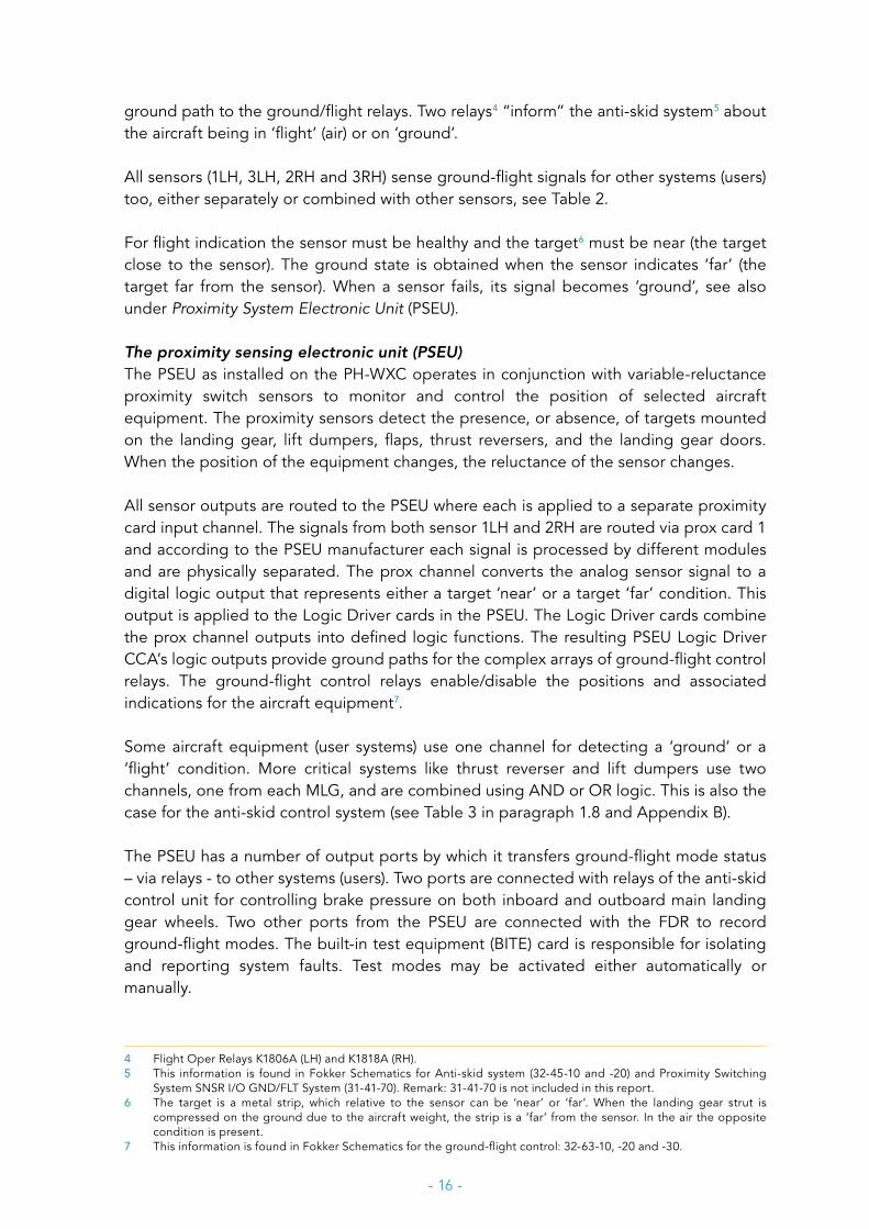
- 16 -
ground path to the ground/flight relays. Two relays4 “inform” the anti-skid system5 about the aircraft being in ‘flight’ (air) or on ‘ground’.
All sensors (1LH, 3LH, 2RH and 3RH) sense ground-flight signals for other systems (users) too, either separately or combined with other sensors, see Table 2.
For flight indication the sensor must be healthy and the target6 must be near (the target close to the sensor). The ground state is obtained when the sensor indicates ‘far’ (the target far from the sensor). When a sensor fails, its signal becomes ‘ground’, see also under Proximity System Electronic Unit (PSEU).
The proximity sensing electronic unit (PSEU)The PSEU as installed on the PH-WXC operates in conjunction with variable-reluctance proximity switch sensors to monitor and control the position of selected aircraft equipment. The proximity sensors detect the presence, or absence, of targets mounted on the landing gear, lift dumpers, flaps, thrust reversers, and the landing gear doors. When the position of the equipment changes, the reluctance of the sensor changes.
All sensor outputs are routed to the PSEU where each is applied to a separate proximity card input channel. The signals from both sensor 1LH and 2RH are routed via prox card 1 and according to the PSEU manufacturer each signal is processed by different modules and are physically separated. The prox channel converts the analog sensor signal to a digital logic output that represents either a target ‘near’ or a target ‘far’ condition. This output is applied to the Logic Driver cards in the PSEU. The Logic Driver cards combine the prox channel outputs into defined logic functions. The resulting PSEU Logic Driver CCA’s logic outputs provide ground paths for the complex arrays of ground-flight control relays. The ground-flight control relays enable/disable the positions and associated indications for the aircraft equipment7.
Some aircraft equipment (user systems) use one channel for detecting a ‘ground’ or a ‘flight’ condition. More critical systems like thrust reverser and lift dumpers use two channels, one from each MLG, and are combined using AND or OR logic. This is also the case for the anti-skid control system (see Table 3 in paragraph 1.8 and Appendix B).
The PSEU has a number of output ports by which it transfers ground-flight mode status – via relays - to other systems (users). Two ports are connected with relays of the anti-skid control unit for controlling brake pressure on both inboard and outboard main landing gear wheels. Two other ports from the PSEU are connected with the FDR to record ground-flight modes. The built-in test equipment (BITE) card is responsible for isolating and reporting system faults. Test modes may be activated either automatically or manually.
4 Flight Oper Relays K1806A (LH) and K1818A (RH).5 This information is found in Fokker Schematics for Anti-skid system (32-45-10 and -20) and Proximity Switching
System SNSR I/O GND/FLT System (31-41-70). Remark: 31-41-70 is not included in this report.6 The target is a metal strip, which relative to the sensor can be ‘near’ or ‘far’. When the landing gear strut is
compressed on the ground due to the aircraft weight, the strip is a ‘far’ from the sensor. In the air the opposite condition is present.
7 This information is found in Fokker Schematics for the ground-flight control: 32-63-10, -20 and -30.
- 17 -
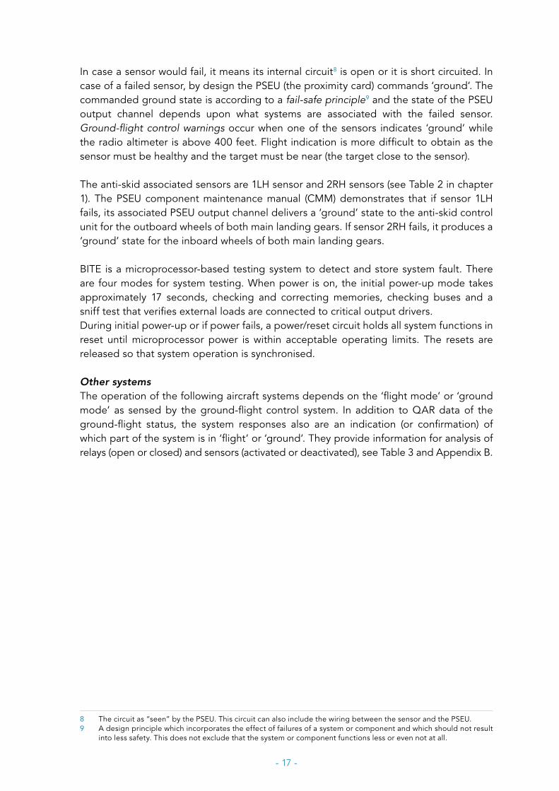
In case a sensor would fail, it means its internal circuit8 is open or it is short circuited. In case of a failed sensor, by design the PSEU (the proximity card) commands ‘ground’. The commanded ground state is according to a fail-safe principle9 and the state of the PSEU output channel depends upon what systems are associated with the failed sensor. Ground-flight control warnings occur when one of the sensors indicates ‘ground’ while the radio altimeter is above 400 feet. Flight indication is more difficult to obtain as the sensor must be healthy and the target must be near (the target close to the sensor).
The anti-skid associated sensors are 1LH sensor and 2RH sensors (see Table 2 in chapter 1). The PSEU component maintenance manual (CMM) demonstrates that if sensor 1LH fails, its associated PSEU output channel delivers a ‘ground’ state to the anti-skid control unit for the outboard wheels of both main landing gears. If sensor 2RH fails, it produces a ‘ground’ state for the inboard wheels of both main landing gears.
BITE is a microprocessor-based testing system to detect and store system fault. There are four modes for system testing. When power is on, the initial power-up mode takes approximately 17 seconds, checking and correcting memories, checking buses and a sniff test that verifies external loads are connected to critical output drivers. During initial power-up or if power fails, a power/reset circuit holds all system functions in reset until microprocessor power is within acceptable operating limits. The resets are released so that system operation is synchronised.
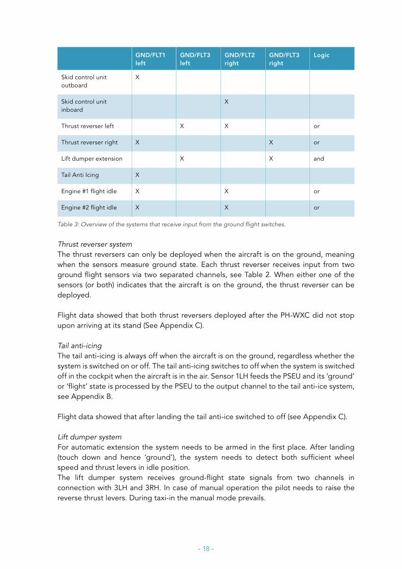
Other systemsThe operation of the following aircraft systems depends on the ‘flight mode’ or ‘ground mode’ as sensed by the ground-flight control system. In addition to QAR data of the ground-flight status, the system responses also are an indication (or confirmation) of which part of the system is in ‘flight’ or ‘ground’. They provide information for analysis of relays (open or closed) and sensors (activated or deactivated), see Table 3 and Appendix B.
8 The circuit as “seen” by the PSEU. This circuit can also include the wiring between the sensor and the PSEU.9 A design principle which incorporates the effect of failures of a system or component and which should not result
into less safety. This does not exclude that the system or component functions less or even not at all.
- 18 -
GND/FLT1 left
GND/FLT3 left
GND/FLT2 right
GND/FLT3 right
Logic
Skid control unit outboard
X
Skid control unit inboard
X
Thrust reverser left X X or
Thrust reverser right X X or
Lift dumper extension X X and
Tail Anti Icing X
Engine #1 flight idle X X or
Engine #2 flight idle X X or
Table 3: Overview of the systems that receive input from the ground flight switches.
Thrust reverser system The thrust reversers can only be deployed when the aircraft is on the ground, meaning when the sensors measure ground state. Each thrust reverser receives input from two ground flight sensors via two separated channels, see Table 2. When either one of the sensors (or both) indicates that the aircraft is on the ground, the thrust reverser can be deployed.
Flight data showed that both thrust reversers deployed after the PH-WXC did not stop upon arriving at its stand (See Appendix C).
Tail anti-icingThe tail anti-icing is always off when the aircraft is on the ground, regardless whether the system is switched on or off. The tail anti-icing switches to off when the system is switched off in the cockpit when the aircraft is in the air. Sensor 1LH feeds the PSEU and its ‘ground’ or ‘flight’ state is processed by the PSEU to the output channel to the tail anti-ice system, see Appendix B.
Flight data showed that after landing the tail anti-ice switched to off (see Appendix C).
Lift dumper systemFor automatic extension the system needs to be armed in the first place. After landing (touch down and hence ‘ground’), the system needs to detect both sufficient wheel speed and thrust levers in idle position. The lift dumper system receives ground-flight state signals from two channels in connection with 3LH and 3RH. In case of manual operation the pilot needs to raise the reverse thrust levers. During taxi-in the manual mode prevails.
- 19 -
Flight data showed that the lift dumper system was armed and deployed after landing, see Appendix C.
Continued airworthinessThe part M (Maintenance) regulation10 of the European Aviation Safety Agency (EASA) specifies the requirements for airworthiness for air carriers and owners of private aircraft based in the European Union (EU) to manage continuing airworthiness. Organisations responsible for continued airworthiness are indicated as continued airworthiness management organisations (CAMO).
In the case of aircraft used by air carriers licensed in accordance with the regulations11 and of complex motor-powered aircraft, the operator should have a system of assessment that should be in operation to support the continuing airworthiness of an aircraft and to provide a continuous analysis of the effectiveness of the (CAMO).
The system should amongst others provide for:
• significant incidents and defects: monitor incidents and defects that have occurred in flight and defects found during maintenance and overhaul, highlighting any that appear significant in their own right.
• repetitive incidents and defects: monitor on a continuous basis defects occurring in flight and defects found during maintenance and overhaul, highlighting any that are repetitive.
• unscheduled removals and system performance: analyse unscheduled component removals and the performance of aircraft systems for use as part of the maintenance programme efficiency.
1.6 Troubleshooting after the event
The troubleshooting was carried out by the maintenance organisation and started on the day of the event, 5 March 2015.
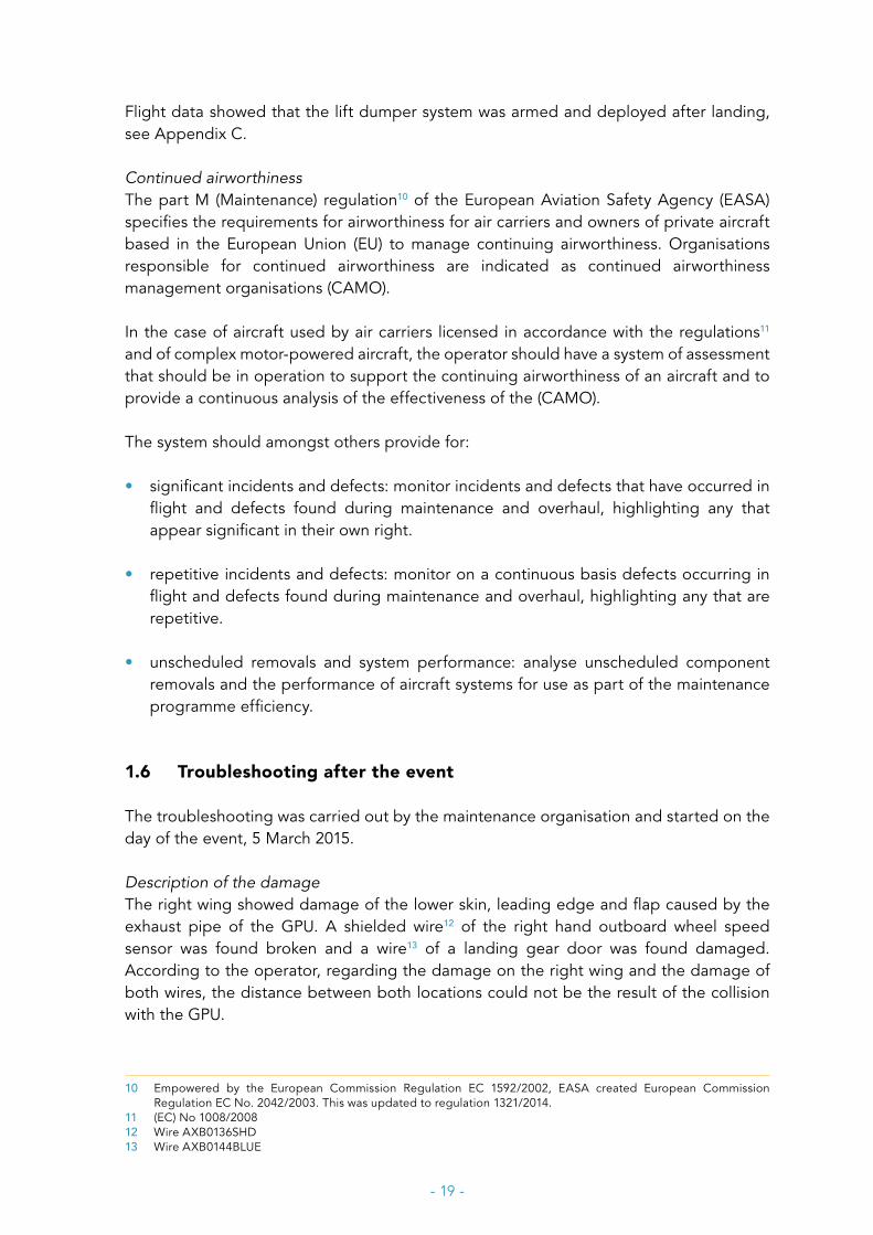
Description of the damageThe right wing showed damage of the lower skin, leading edge and flap caused by the exhaust pipe of the GPU. A shielded wire12 of the right hand outboard wheel speed sensor was found broken and a wire13 of a landing gear door was found damaged. According to the operator, regarding the damage on the right wing and the damage of both wires, the distance between both locations could not be the result of the collision with the GPU.
10 Empowered by the European Commission Regulation EC 1592/2002, EASA created European Commission Regulation EC No. 2042/2003. This was updated to regulation 1321/2014.
11 (EC) No 1008/200812 Wire AXB0136SHD13 Wire AXB0144BLUE
- 20 -
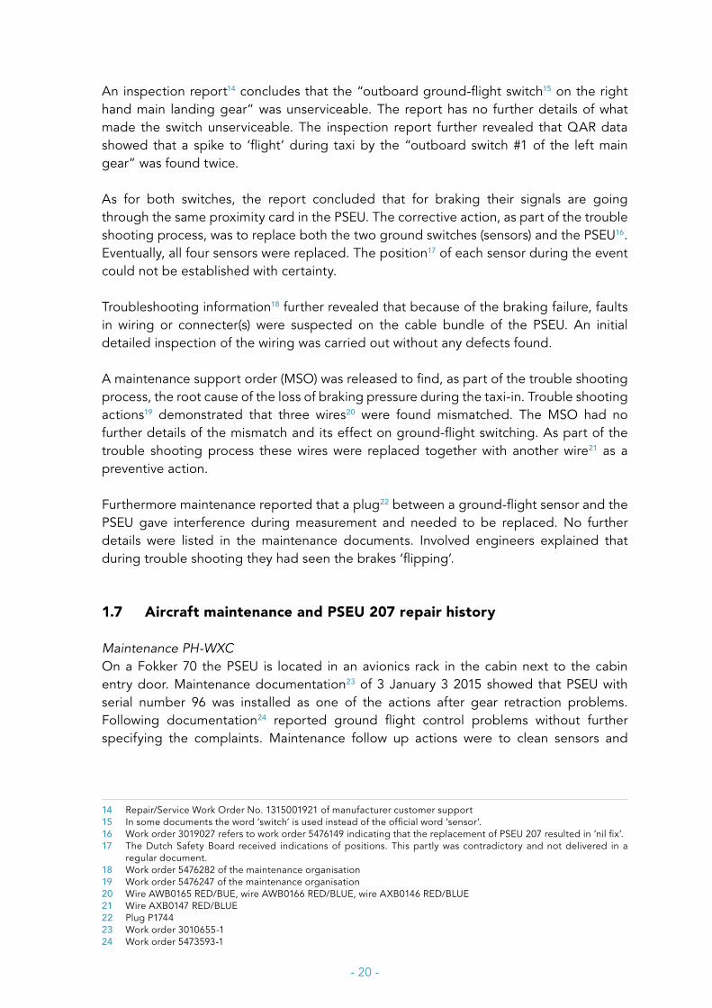
An inspection report14 concludes that the “outboard ground-flight switch15 on the right hand main landing gear” was unserviceable. The report has no further details of what made the switch unserviceable. The inspection report further revealed that QAR data showed that a spike to ‘flight’ during taxi by the “outboard switch #1 of the left main gear” was found twice.
As for both switches, the report concluded that for braking their signals are going through the same proximity card in the PSEU. The corrective action, as part of the trouble shooting process, was to replace both the two ground switches (sensors) and the PSEU16. Eventually, all four sensors were replaced. The position17 of each sensor during the event could not be established with certainty.
Troubleshooting information18 further revealed that because of the braking failure, faults in wiring or connecter(s) were suspected on the cable bundle of the PSEU. An initial detailed inspection of the wiring was carried out without any defects found.
A maintenance support order (MSO) was released to find, as part of the trouble shooting process, the root cause of the loss of braking pressure during the taxi-in. Trouble shooting actions19 demonstrated that three wires20 were found mismatched. The MSO had no further details of the mismatch and its effect on ground-flight switching. As part of the trouble shooting process these wires were replaced together with another wire21 as a preventive action.
Furthermore maintenance reported that a plug22 between a ground-flight sensor and the PSEU gave interference during measurement and needed to be replaced. No further details were listed in the maintenance documents. Involved engineers explained that during trouble shooting they had seen the brakes ‘flipping’.
1.7 Aircraft maintenance and PSEU 207 repair history
Maintenance PH-WXCOn a Fokker 70 the PSEU is located in an avionics rack in the cabin next to the cabin entry door. Maintenance documentation23 of 3 January 3 2015 showed that PSEU with serial number 96 was installed as one of the actions after gear retraction problems. Following documentation24 reported ground flight control problems without further specifying the complaints. Maintenance follow up actions were to clean sensors and
14 Repair/Service Work Order No. 1315001921 of manufacturer customer support15 In some documents the word ‘switch’ is used instead of the official word ‘sensor’.16 Work order 3019027 refers to work order 5476149 indicating that the replacement of PSEU 207 resulted in ‘nil fix’.17 The Dutch Safety Board received indications of positions. This partly was contradictory and not delivered in a
regular document.18 Work order 5476282 of the maintenance organisation19 Work order 5476247 of the maintenance organisation20 Wire AWB0165 RED/BUE, wire AWB0166 RED/BLUE, wire AXB0146 RED/BLUE21 Wire AXB0147 RED/BLUE22 Plug P174423 Work order 3010655-124 Work order 5473593-1

- 21 -
targets and to replace the PSEU. On 9 January 2015 PSEU with serial number 96 was taken out of PH-WXC and replaced by PSEU with serial number 207 (PSEU 207).
After power up of the aircraft a ‘proximity system inoperative and degraded’ report was generated on MFDS. It appeared that the PSEU gave a CPU/Card fault (code E325). During maintenance power up and power down was repeated 10 times without reproducing the reported fault. Thereafter the PSEU passed its self-test.
Work order documentation from 13 January through 7 February 2015, prior to the event and as far as relevant, showed a few repetitive AC 1 faults after shutting down engine #1 or shutting down engine #2. In one case the circuit breaker of the generator control unit (GCU) was found tripped. The GCU was replaced. In the other case(s) the faults could not be reproduced during maintenance.
On 4 March 2015, the evening before the event, the PH-WXC was in maintenance. As far as relevant, in order to comply with a Service Bulletin26, a water boiler was removed to allow the modification of water connectors and re-installed afterwards. A light in the cargo compartment was found unserviceable due to a damaged wire. The wire was repaired.
Replacing LRUs during troubleshooting for shop repair processesThe replacement of a LRU (for instance an avionics unit like a PSEU), especially when under time pressure, might be an effective maintenance action of ground engineers to release the aircraft back to service when the complaint seems to be solved with a different LRU installed. The replaced LRU may be repaired and sometimes, despite indications the LRU does not work well, no anomalies or failures can be found. In any case, a LRU is tested and when it passes the test it can be re-installed in airworthy condition.
In some cases more parts (i.e. plugs, sensors, switches et cetera) are replaced during the same troubleshooting period as an attempt to quickly regain serviceability of the aircraft. These simultaneous replacements increase chances of ‘no evidence of failure’ (NEOF) when a LRU is inspected and tested in the repair shop.
Fokker Services provided statistical information regarding the number of times a LRU is sent to a shop for either repair or overhaul. It showed 721 shop visits since 1998 of 56 PSEU’s27 with the highest number of shop visits removed. For these units this means an average of 12,9 visits per unit during the last 21 years. Based on this list PSEU 207 had 8 shop visits, which included 5 known28 unscheduled removals since 2012.
25 Code E3: fault related to prox card 2 of the PSEU26 Service Bulletin 908: modification of the connectors of a slide rack of a water boiler.27 The statistical information of the manufacturer is not limited to 56 serial numbers (56 individual PSEU’s), but the
received information represents the shop visits of 56 units with the highest number of shop visits including PSEU 207 ranked at position 56.
28 It was not established whether the 3 remaining shop visits were scheduled or unscheduled.
- 22 -
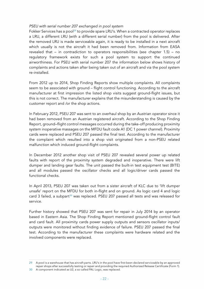
PSEU with serial number 207 exchanged in pool system Fokker Services has a pool29 to provide spare LRU’s. When a contracted operator replaces a LRU, a different LRU (with a different serial number) from the pool is delivered. After the removed LRU is made serviceable again, it is ready to be installed in a next aircraft which usually is not the aircraft it had been removed from. Information from EASA revealed that – in contradiction to operators responsibilities (see chapter 1.5) – no regulatory framework exists for such a pool system to support the continued airworthiness. For PSEU with serial number 207 the information below shows history of complaints and actions taken after being taken out of an aircraft and via the pool system re-installed.
From 2012 up to 2014, Shop Finding Reports show multiple complaints. All complaints seem to be associated with ground – flight control functioning. According to the aircraft manufacturer at first impression the listed shop visits suggest ground-flight issues, but this is not correct. The manufacturer explains that the misunderstanding is caused by the customer report and /or the shop actions.
In February 2012, PSEU 207 was sent to an overhaul shop by an Austrian operator since it had been removed from an Austrian registered aircraft. According to the Shop Finding Report, ground–flight control messages occurred during the take-off producing proximity system inoperative massages on the MFDU fault code A1 (DC 1 power channel). Proximity cards were replaced and PSEU 207 passed the final test. According to the manufacturer the complaint which resulted into a shop visit originated from a non-PSEU related malfunction which induced ground-flight complaints.
In December 2012 another shop visit of PSEU 207 revealed several power up related faults with report of the proximity system degraded and inoperative. There were lift dumper and landing gear faults. The unit passed the built-in test equipment test (BITE) and all modules passed the oscillator checks and all logic/driver cards passed the functional checks.
In April 2013, PSEU 207 was taken out from a sister aircraft of KLC due to ‘lift dumper unsafe’ report on the MFDU for both in-flight and on ground. As logic card 4 and logic card 3 failed, a subpart30 was replaced. PSEU 207 passed all tests and was released for service.
Further history showed that PSEU 207 was sent for repair in July 2014 by an operator based in Eastern Asia. The Shop Finding Report mentioned ground-flight control fault and card fault. All proximity cards power supply outputs and sensors oscillator inputs/outputs were monitored without finding evidence of failure. PSEU 207 passed the final test. According to the manufacturer these complaints were hardware related and the involved components were replaced.
29 A pool is a warehouse that has aircraft parts. LRU’s in the pool have first been declared serviceable by an approved repair shops after successfully testing or repair and providing the required Authorized Release Certificate (Form 1).
30 A component indicated as U2, a so called PAL Logic, was replaced.
- 23 -
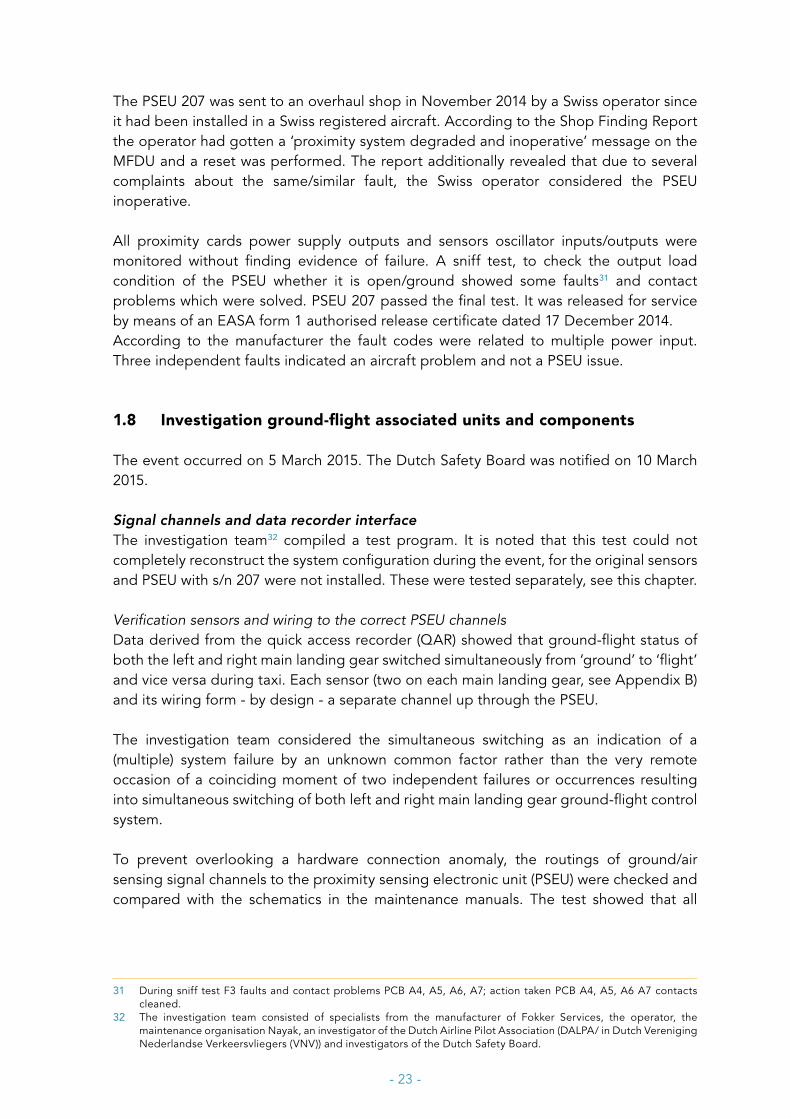
The PSEU 207 was sent to an overhaul shop in November 2014 by a Swiss operator since it had been installed in a Swiss registered aircraft. According to the Shop Finding Report the operator had gotten a ‘proximity system degraded and inoperative’ message on the MFDU and a reset was performed. The report additionally revealed that due to several complaints about the same/similar fault, the Swiss operator considered the PSEU inoperative.
All proximity cards power supply outputs and sensors oscillator inputs/outputs were monitored without finding evidence of failure. A sniff test, to check the output load condition of the PSEU whether it is open/ground showed some faults31 and contact problems which were solved. PSEU 207 passed the final test. It was released for service by means of an EASA form 1 authorised release certificate dated 17 December 2014. According to the manufacturer the fault codes were related to multiple power input. Three independent faults indicated an aircraft problem and not a PSEU issue.
1.8 Investigation ground-flight associated units and components
The event occurred on 5 March 2015. The Dutch Safety Board was notified on 10 March 2015.
Signal channels and data recorder interfaceThe investigation team32 compiled a test program. It is noted that this test could not completely reconstruct the system configuration during the event, for the original sensors and PSEU with s/n 207 were not installed. These were tested separately, see this chapter.
Verification sensors and wiring to the correct PSEU channels Data derived from the quick access recorder (QAR) showed that ground-flight status of both the left and right main landing gear switched simultaneously from ‘ground’ to ‘flight’ and vice versa during taxi. Each sensor (two on each main landing gear, see Appendix B) and its wiring form - by design - a separate channel up through the PSEU.
The investigation team considered the simultaneous switching as an indication of a (multiple) system failure by an unknown common factor rather than the very remote occasion of a coinciding moment of two independent failures or occurrences resulting into simultaneous switching of both left and right main landing gear ground-flight control system.
To prevent overlooking a hardware connection anomaly, the routings of ground/air sensing signal channels to the proximity sensing electronic unit (PSEU) were checked and compared with the schematics in the maintenance manuals. The test showed that all
31 During sniff test F3 faults and contact problems PCB A4, A5, A6, A7; action taken PCB A4, A5, A6 A7 contacts cleaned.
32 The investigation team consisted of specialists from the manufacturer of Fokker Services, the operator, the maintenance organisation Nayak, an investigator of the Dutch Airline Pilot Association (DALPA/ in Dutch Vereniging Nederlandse Verkeersvliegers (VNV)) and investigators of the Dutch Safety Board.
- 24 -
channels from the sensors up through the PSEU matched with the schematic and showed signal continuity.
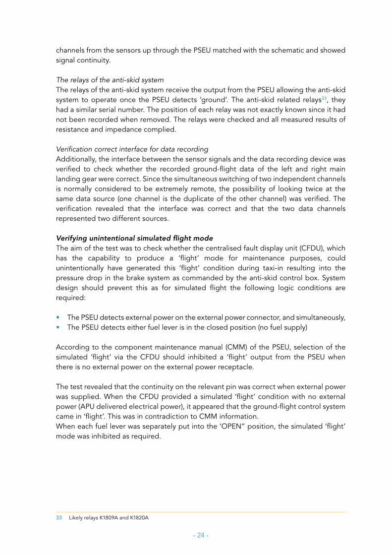
The relays of the anti-skid systemThe relays of the anti-skid system receive the output from the PSEU allowing the anti-skid system to operate once the PSEU detects ‘ground’. The anti-skid related relays33, they had a similar serial number. The position of each relay was not exactly known since it had not been recorded when removed. The relays were checked and all measured results of resistance and impedance complied.
Verification correct interface for data recordingAdditionally, the interface between the sensor signals and the data recording device was verified to check whether the recorded ground-flight data of the left and right main landing gear were correct. Since the simultaneous switching of two independent channels is normally considered to be extremely remote, the possibility of looking twice at the same data source (one channel is the duplicate of the other channel) was verified. The verification revealed that the interface was correct and that the two data channels represented two different sources.
Verifying unintentional simulated flight mode The aim of the test was to check whether the centralised fault display unit (CFDU), which has the capability to produce a ‘flight’ mode for maintenance purposes, could unintentionally have generated this ‘flight’ condition during taxi-in resulting into the pressure drop in the brake system as commanded by the anti-skid control box. System design should prevent this as for simulated flight the following logic conditions are required:
• The PSEU detects external power on the external power connector, and simultaneously,• The PSEU detects either fuel lever is in the closed position (no fuel supply)
According to the component maintenance manual (CMM) of the PSEU, selection of the simulated ‘flight’ via the CFDU should inhibited a ‘flight’ output from the PSEU when there is no external power on the external power receptacle.
The test revealed that the continuity on the relevant pin was correct when external power was supplied. When the CFDU provided a simulated ‘flight’ condition with no external power (APU delivered electrical power), it appeared that the ground-flight control system came in ‘flight’. This was in contradiction to CMM information. When each fuel lever was separately put into the ‘OPEN” position, the simulated ‘flight’ mode was inhibited as required.
33 Likely relays K1809A and K1820A
- 25 -
Bench testing PSEU and ground-flight sensors
Proximity electronics sensing unitThe manufacturer carried out a complete acceptance test procedure (ATP) for PSEU 207. In summary, the tests verify proper interconnection of all circuit cards and its chassis. The PSEU shall be tested to verify proper operation of all sensor input channels and output channels. PSEU 207 passed the full ATP test.
During the full ATP test a momentarily flickering of test lamps occurred, which was not expected. Because of this, an extra ground-flight control logic test was performed. This extra test could not reproduce the flickering.
Ground-flight sensors All four sensors were tested at the facility of the manufacturer of the PSEU. Three sensors had a part number and serial number. One sensor did not show either part number or serial number. No explanation was found where this sensor came from.
The sensors were tested on electrical resistance, impedance and insulation resistance. Furthermore, the (disturbance of) induction was measured and compared to reference test material for ‘Guaranteed activation’ (Ga) and ‘Guaranteed deactivation’ (Gd). No hard failures were found. The sensor without part and serial number showed a slight deviation of the specification requirements.
Additionally, the PSEU manufacturer performed an acceptance test procedure (ATP) of all four sensors and provided an additional report of the sensor without part and serial number since it showed slight deviations compared to the “ideal” values necessary to pass the ATP automatically.
The ATP results slightly differed from the initial (hand performed) test and a possible explanation of the PSEU manufacturer was a difference in values between new and in service material. All four sensors functioned and there was no evidence that could explain the ground to flight switching. The three sensors with part and serial numbers passed the test.
In view of the PSEU manufacturer the deviations of the fourth sensor were minor and it was believed the sensor worked on the PH-WXC.
Circuit BreakersThe 4 power supply circuit breakers of the PSEU were tested in open and closed positions and no anomalies were found. The position of each circuit breaker during the incident had not been recorded.
Power up test of the PSEU October 2017CMM information learned that the initial power-up mode of the PSEU lasts approximately 17 seconds. During the event the transponder signal – and hence radar - was lost for approximately 17 seconds as well. The aim of the test was to verify whether these time intervals were related, and if so, if the loss of radar signal was an indication that the PSEU
- 26 -
might have lost AC power shortly followed by a power-up. In that case it would be interesting to know whether this would alter ground to flight output of the PSEU.
PSEU output responses were verified by using the electronic flight information system (EFIS) responses. When EFIS receives an on ground signal the speed scale is presented on EFIS. If the signal is in ‘flight’, a speed (SPD) flag is presented. The LH EFIS is connected to PSEU MLG sensor 1LH (via ground operating relay), the RH EFIS is connected to the PSEU MLG sensor 2RH (via ground operating relay).Start of test: aircraft on ground with proper EFIS indications, FDR started by means of opening the fuel shut off lever. When targets to simulate ‘air’ were present on MLG sensors 1LH and 2RH, the opening or closure of the PSEU channel PWR 1 and 2 CB’s had no effect. When the targets were removed and thereafter the CB’s PSEU channel PWR 1 and 2 were reset, the FDR and EFIS showed on ground as expected. In this test simulated power switching (simulating loss of generated power) did not result in latched type incorrect outputs.
Self-testingSelf-test is only activated when power was previously removed from the PSEU (also emergency bus). The self-test was not activated when PSEU channels PWR 1 and 2 were tripped while the emergency bus remained powered (E1 and E2). The self-test provided a very short in air indication (can hardly be seen on EFIS). First the LH EFIS showed momentarily the SPD flag, and thereafter the RH EFIS.
1.9 Investigation electromagnetic interference
Other type of aircraft Transport Canada issued an Airworthiness Directive (AD) No CF-93-20 which became effective on 31 August 1993. The AD addressed a fault produced by the electrical power supplies of the anti-collision light on certain De Havilland34 DHC-8 aircraft which did not have a modified version35 installed. The fault may produce a strong parasitic electronic waveform. When coupled into the wiring of the PSEU, the waveform can adversely affect operation of the associated systems.
In summary, the incorrect operation of the PSEU could result into disturbances of indication systems36 during cruise flight. For ground operations37 it could affect flight control systems, nose wheel steering system and no normal wheel braking available when the speed was below 35-40 knots. To preclude incorrect PSEU operation the AD prescribed requirements to comply with. Both the PSEU installed in the DHC-8 (200/300 series) and the PSEU in the Fokker 70/100 are from the same manufacturer.
34 The current type certificate holder is Bombardier Commercial Aircraft.35 It concerned Modification 8/1273 to be incorporated.36 Flashing of the landing gear green locked down, advisory light, fluctuation of the cabin pressurization rate needle37 Retraction and extension of roll land ground spoilers, nose gear steering inoperative subsequent to landing,
- 27 -
During the investigation this AD was discussed38 with the manufacturer of the PSEU in the Fokker 70/100. More information to better understand EMI protection could not be shared by the manufacturer of the PSEU, because it did not grant permission of the concerned aircraft manufacturer and involved safety investigation agency to release any of the details39.
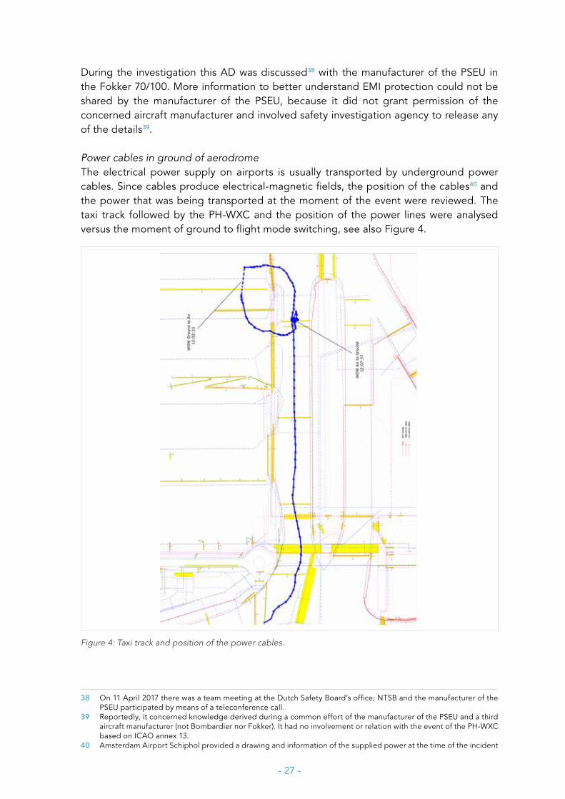
Power cables in ground of aerodromeThe electrical power supply on airports is usually transported by underground power cables. Since cables produce electrical-magnetic fields, the position of the cables40 and the power that was being transported at the moment of the event were reviewed. The taxi track followed by the PH-WXC and the position of the power lines were analysed versus the moment of ground to flight mode switching, see also Figure 4.
Figure 4: Taxi track and position of the power cables.
38 On 11 April 2017 there was a team meeting at the Dutch Safety Board’s office; NTSB and the manufacturer of the PSEU participated by means of a teleconference call.
39 Reportedly, it concerned knowledge derived during a common effort of the manufacturer of the PSEU and a third aircraft manufacturer (not Bombardier nor Fokker). It had no involvement or relation with the event of the PH-WXC based on ICAO annex 13.
40 Amsterdam Airport Schiphol provided a drawing and information of the supplied power at the time of the incident
- 28 -
1.10 Electrical power switching and ground-flight
During flight the electrical load of the Fokker F70 (and F100) is divided over 2 generators, one installed on each engine. Each generator feeds its own (AC and DC) buses. Engine shut down results into an automatic switching of the affected buses to the generator driven by remaining engine. The transfer of electrical power takes place via the bus transfer relays.
After landing, the crew of the PH-WXC chose to shut down engine #2, whereupon AC and DC buses of generator #2 automatically switched to generator #1.
Possible ground-flight switching following engine shut down In August 2015 KLC experienced intermittent electrical power supply (fault conditions) of a Fokker F70 aircraft (PH-KZP) which could not be reproduced during the trouble shooting process. The operator found that ultimately DC bus #1 was not fed via transfer buses when only generator #2 supplied electrical power. Its report further revealed that during trouble shooting/testing, when one engine (either engine #1 or engine #2) was shut down, resulted in a number of faults on the MFDS. These included the proximity switching system. Most of them were self-clearing faults which disappeared after one minute. It was reported41 to Fokker Services to request support.
According to information on the work order42 (WO) Fokker Services analysed that the long lasting electrical power switching was caused by a sensor of the right hand MLG. Additional reporting43 by Fokker revealed that this sensor switched when engine #2 was shut down and once engine #2 had spooled down to approximately 50% rpm generator #2 switched off.
QAR data showed no other sensors switched at the same moment and no other DC #2 faults were found. Fokker concluded the switching of the right hand MLG sensor to be the root cause of the ground-flight switching of the PSEU in the PH-KZP.
1.11 Other occurrences
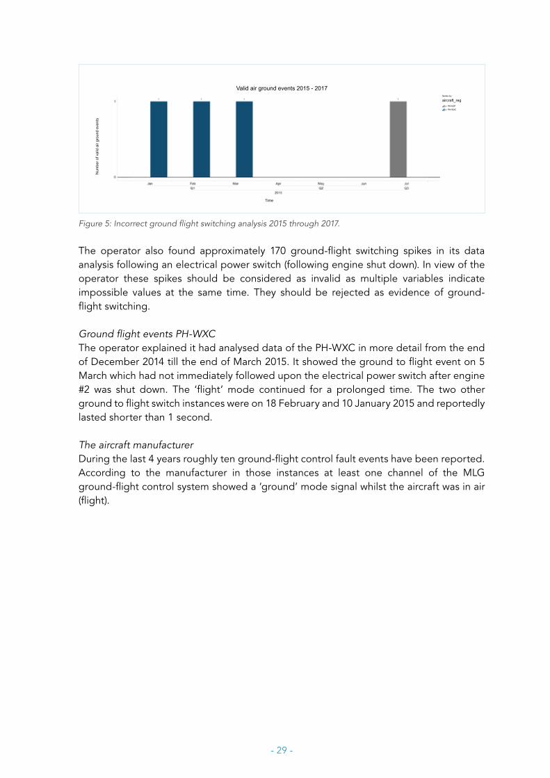
Ground-flight events operator fleetThe operator stated that it analysed Fokker F70/100 fleet data - as a review due to the event with the PH-WXC - over the period 2015-2017, see Figure 5.The figure represents three reports (not spikes) of ground flight switching of the PH-WXC (10 January, 18 February, 5 March 2015) and one of the PH-KZP (July 2015). No ground-flight switching events were observed in 2016 and 2017.
41 CAS-45106-5B72TN, reference Nayak WO#308522442 Work order WO6299287 dated 12 August 201543 CAS-45106-5B74TN, reference Nayak WO#3085224 answer date 2 September 2015
- 29 -
Time
Num
ber o
f val
id a
ir gr
ound
eve
nts
Series by:
aircraft_regx_PH-KZPx_PH-WXC
Valid air ground events 2015 - 2017
Figure 5: Incorrect ground flight switching analysis 2015 through 2017.
The operator also found approximately 170 ground-flight switching spikes in its data analysis following an electrical power switch (following engine shut down). In view of the operator these spikes should be considered as invalid as multiple variables indicate impossible values at the same time. They should be rejected as evidence of ground-flight switching.
Ground flight events PH-WXCThe operator explained it had analysed data of the PH-WXC in more detail from the end of December 2014 till the end of March 2015. It showed the ground to flight event on 5 March which had not immediately followed upon the electrical power switch after engine #2 was shut down. The ‘flight’ mode continued for a prolonged time. The two other ground to flight switch instances were on 18 February and 10 January 2015 and reportedly lasted shorter than 1 second.
The aircraft manufacturer During the last 4 years roughly ten ground-flight control fault events have been reported. According to the manufacturer in those instances at least one channel of the MLG ground-flight control system showed a ‘ground’ mode signal whilst the aircraft was in air (flight).
- 30 -
2 ANALYSIS
2.1 Loss of control and risks
The loss of braking capacity immediately posed a risk for the two ground handlers which had the attentiveness to run away to avoid being hit or being run over. The evasive manoeuvre made by the pilots and their action to shut down the remaining engine limited the consequences of having lost braking capacity of the aircraft. A favourable factor was the absence of other obstacles and traffic nearby minimising the chances of another collision.
Both pilots were properly licensed.
2.2 Ground to flight switching and braking during taxi
Damaged wiring No complaints related to braking prior to the inbound flight to Amsterdam had been reported by the crew or found in the aircraft tech log ATL and maintenance books.
No aircraft system indications (like warnings) nor available maintenance information confirmed that the damaged and broken wiring (cables of wheel speed sensor and landing gear door (see 1.6 Description of damage) already existed prior to the event. This might indicate the damage resulted from the collision, also because the damaged and broken cables and GPU were all on the right hand side.
However, according to the operator it was not possible that the GPU hit the wiring since the distance between the wiring and damaged area of the wing was too large. This suggests that the cables were already damaged. Unfortunately, no evidence of the collision dynamics was recorded during the troubleshooting process, which could have either confirmed or denied the likelihood that the wiring was already damaged.
It cannot be ruled out that the damaged cables disturbed finding the cause of the ground to flight mode switching during the troubleshooting as part of the normal maintenance process.
Data analysis of spikes and loss of ground radar A spike can be an erroneous indication meaning that the observed ground to flight switch had not really occurred. Still, it is possible that the affected channels really flipped shortly to flight and back to ground. In that case the effect cannot be confirmed by responses in user systems since the time is too short for system response. Therefore, the data spikes could not support a proper ground-flight switching analysis.
- 31 -
CVR information showed a strongly dimmed sine wave which could not be identified as from aural nature. It seems, however, to (approximately) coincide with the start of a 17 seconds lasting time interval during which ground radar was lost. After that, PH-WXC came back on ground radar. Since a 17 seconds interval also is a feature of a power up mode of the PSEU, an interconnection was suspected. However, the suspected ‘17 seconds commonality’ did not support the thesis that the ground-flight switching was the result of power interruption (see 2.4 Power up test). Also, no connection with the sine wave as found on the CVR could be established.
The loss of braking pressureDuring the first (and major part) of the taxi-in the brake system performed well and responded on demand.
As evidenced by QAR data (see Appendix C) and aircraft user system responses, a part of the ground-flight system switched into the ‘flight’ (air) mode during taxi-in. Consequently, all two ‘flight’ signal outputs (channel 1LH and channel 2RH) of the PSEU were sent - via the relay(s) - to the anti-skid control box unit activating the anti-skid system to dump the braking pressure of both the inner and outer wheels.
As far as it concerns the availability of brakes it did not matter that only engine #1 was running during taxi-in, for each engine supplies hydraulic pressure to both the normal and alternate brake system. As indicated by schematic of the brake system (see appendix A), the skid control box commanded - as designed - to dump the brake pressure of both brake systems after which the attempts of the crew to brake failed. It is concluded that all aircraft systems related to braking functioned correctly, except a part of the ground-flight system.
Ground- flight system logic (see 1.5 Aircraft systems and continued airworthiness, Table 3) allowed thrust reversers to deploy when selected by the first officer, however, with one engine running at flight idle it had no noticeable effect. Since sensor 3LH also provides a ‘ground’ state (as well as 2RH) for engine thrust reverser #1 and sensor 3RH also provides a ‘ground’ state (as well as 3RH) for engine thrust reverser #2, the activation of the thrust reversers during taxi-in did not prove that (only) channels 1LH and 2RH were in ‘flight’ state.
Sudden return of brake pressureBy shutting down the remaining engine – and with no APU running - no electrical power from any generator was available, except emergency power from the emergency busses supplied by a battery. Since the anti-skid control box is not powered by any emergency busses, the full dump signal was also removed from the anti-skid control. Consequently, brake pressure (now from the hydraulic brake accumulator) instantly returned causing an abrupt stop as the pilots still applied the brake pedals, see the skid marks in Figure 2.
It is mentioned that the concerned part of the ground-flight system still remained in ‘flight’ after engine #1 had been shut down. The PSEU remained working since it, by absence of AC power, was supplied by a battery via emergency busses.
- 32 -
2.3 Analysing ground-flight control on aircraft system level
System design Evidence suggests that the PH-WXC was in an airworthy condition prior to departure from Durham/Teesside and there was no indication that a serious aircraft system failure was imminent.
On system level, despite dual hydraulics and dual brake systems, the crew no longer had full control over the aircraft since all braking authority was lost. Still, the ground-flight control system sensed ‘ground’ as correct state via 3LH and 3RH channels. Since by design the 1LH is not compared with 3LH and 2RH is not compared with 3RH, the possibility of an incorrect state of one of the inputs to the PSEU remained unnoticed. For an overview of the PSEU channels and user systems logic routing, see Appendix B.
System design is such that in this case a failure in the ground-flight control system limited the consequences to the brake system and engine operation. The pressure in the brake system was dumped and the engine thrust #1 increased from ground idle to flight idle, see also table 2. In the overall aircraft design the risk of a ground-flight failure is spread, because other system users are interconnected with the channels of sensors 3LH and 3RH. These channels remained in the ‘ground’ mode which was the correct state during taxi.
System responses based upon ground-flight controlConsidering the channels to which each sensor is connected (see Table 3 in paragraph 1.5) and the full loss of braking capacity during taxi, the pressure of both inboard and outboard brakes must have been dumped simultaneously. Also the FDR/QAR interface was found to be correct (see paragraph 1.8).
Reviewing QAR data and considering aircraft systems design, the occurrence of flight idle mode of engine #1 during taxi-in confirmed that both Left and Right main landing gear were in ‘flight’ mode (see Appendix B, sensor 1LH in green and sensor 2RH in yellow). Therefore, main landing gear ground-flight signals as seen on QAR were not each other duplicate44 (one way or the other) but separated channels with valid information. The input from the 1LH and 2RH ground-flight sensors are processed by prox card 1 and logic card 1 and prox card 1 and logic card 2, respectively.
The fact that engine thrust reverse could be selected implied that also a ‘ground’ mode was still present and that ground-flight switches 3LH and 3RH did not switch from ground to flight. The left-hand thrust reverser can be deployed when the input from sensor 3LH, processed by prox card 2 and logic card 3, and sensor 2RH, processed by prox card 1 and logic card 2, can be combined by OR logic into a ground state (see Appendix B, routing denoted in green and magenta for the right-hand thrust reverser and blue and yellow for the left-hand reverser). Hence, apart from QAR data, system responses confirmed that not all channels of the ground-flight control system were in ‘flight’. With
44 Since the simultaneous switching of two separated channels due to a double failure is so remote, the investigation team initially took into account the possibility that QAR showed twice the same data on each channel.
- 33 -
reference to Appendix B, the absence of warnings combined with the fact that QAR data of left and right MLG channels were identical, indicates that logic cards 3 and 4 functioned correctly.
Since the QAR (see Table 2 in paragraph 1.4) recorded simultaneous ground-flight switching via the same input channels as the anti-skid unit but via different output ports from the PSEU, it is unlikely that the wiring between PSEU and anti-skid system played a role. Consequently, based on system design the incorrect ground to flight switching likely was affected by either the PSEU, its sensors 1LH and/or 2RH, or the wiring between the PSEU and these sensors. It is concluded that the ground-flight control system partially was in ‘flight’ and that there must be a “system or component explanation” for the simultaneous switching. Indeed, it normally is extremely remote that two independent and separated channels would switch simultaneously due to an erratic sensor signal in each channel. Aircraft user system responses (see Table 3 in 1.5) confirmed that the failure affected the channels of the 1LH and 2RH sensors. System responses further showed that the other channels (connected to sensor 3LH and 3RH) remained intact and its sensor remained in ‘ground’ state. These channels are mostly separated and are processed by different logic cards, being logic card 1 and 2. However, the commonality between both channels is that the sensor values are converted to discrete outputs by prox card number 1. This might be an indication that whatever caused the simultaneous switching seems to be linked to the functioning of prox card 1.
Troubleshooting the ground-flight control system Maintenance documentation suggested anomalies for a RH MLG sensor, wiring and connector plug and engineers observed the flipping of the brakes and no improvement after replacing PSEU 207, see 1.6 Troubleshooting after the event. Without details no further in-depth analysis could be made. Sensors, wiring and PSEU were all replaced and not all positions and troubleshooting conditions were recorded accurately. This hampered the analysis of the effects of the damaged wheel speed sensor wiring and damaged landing gear door wiring on the troubleshooting results. This is understandable from the perspective of the troubleshooting process, which primarily aimed for getting the aircraft back into service. This was not in the interest of the safety investigation.
An additional test on the PH-WXC carried out later, as part of the investigation by the Dutch Safety Board did not reveal anomalies in the channels (wires) from sensors to PSEU output ports and from there to the relays to the anti-skid box. As for investigating line replaceable units (LRU’s) and components and testing them, see 2.4 Analysing ground-flight control on component level.
- 34 -
2.4 Analysing ground-flight control on component level
Two LRU’s were investigated as they both (may) affect the flight and ground mode output of the PSEU. The most remarkable finding in the QAR data was the simultaneous switching from ground mode to flight of both the concerned channels (1LH sensor and 2RH sensor) on the left and right main landing gears.
Circuit breakers and relaysThe circuit breakers feeding the PSEU were tested and worked well.
The design of the anti-skid and brake control system shows that four relays should have failed at the same time to realise a brake failure which normally is extremely unlikely to occur. Also, the relays of the PH-WXC controlling the anti-skid system met the requirements when measured. Therefore, it is concluded that the relays and circuit breakers functioned correctly.
Centralised Fault Display Unit (CFDU) and The self-test of the CFDU, as part of the troubleshooting process, revealed no anomalies. Also the test performed on the PH-WXC, as part of the investigation process (see 1.8), did not show CFDU related flaws. Therefore there is no evidence that functioning of the CFDU (as LRU) caused a false ‘flight’ output from the PSEU.
Still, for maintenance purposes the CFDU can generate a flight condition for both left and right main landing gear by simulating the flight mode. A test on the PH-WXC (November 2015), as part of the safety investigation, demonstrated that to realise simulated ‘flight’ mode the fuel levers needed to be in the ‘CLOSED’ position as required. However, simulated ‘flight’ was possible without external power connected, which was not as required.
CFDU flight simulated mode would be a good explanation for a simultaneous switching of both left and right main landing gear system. However, as engine #1 was still operating during taxi, its fuel lever was in the ‘OPEN’ position preventing a ‘flight’ mode activation in the unlikely event that the CFDU would have given an un-commanded ‘flight’ mode input to the PSEU. Therefore, it can be ruled out that the CFDU activated a partial ‘flight’ mode in the ground-flight control system.
The results of the test also indicated that the equations in the CMM, related to external power, were not in accordance with the actual logics as found on the PH-WXC. The manufacturer of the PSEU corrected the equations accordingly in the CMM. It is noted however that these deviations in the logic had no relation with the event.
The test further demonstrated that the wiring channels on the PH-WXC were in accordance with the AMM schematics and the relays which effectuated the ‘flight’ mode to the anti-skid unit control box, met the requirements.
- 35 -
Proximity Sensing Electronic Unit (PSEU) and sensors
Fault codes and possible sensor failureThe fault codes of the inbuilt self-test of the PSEU, as part of the troubleshooting process by the maintenance organisation, showed no indication of an unstable operation of the ground-flight control system. This included the lift dumper message on the MFDU during taxi-in noticed by the crew. The flipping of the wheel brakes could not be explained.
Also during a repair shop inspection, despite a defect pin and the lack of solder on a print board no evidence of PSEU failure was found and the output of the prox cards met the requirements. It is concluded that though irregularities were found, based upon the initial shop inspection no relation with ground–flight switching could be established.
Since the brake pressure of both inboard and outboard wheels was dumped as commanded by the anti-skid control unit, it is concluded the output states of both channels were ‘flight’. In case of a failed sensor, as explained in 1.4, the PSEU output state of the concerned channel would be ‘ground’. Consequently, as no ‘ground’ state was present both sensor 1LH channel and 2RH channel were not in a failed condition but healthy. This conclusion is in line with the testing results of the sensors at the manufacturer facility, see below.
Testing at manufacturerThe bench test of the PSEU did not indicate an anomaly that could explain a failure of the ground-flight system since it passed all items of the acceptance test procedure (ATP).
The location of each sensor could not be reconstructed with certainty since their positions on the main landing gear disassembly had not been recorded during disassembly. This limited the failure analysis, in particular whether the sensor without a part number and without serial number was connected to either channel which produced a ‘flight’ output coming from the PSEU. Inspection of the sensors revealed minor deviations with one sensor, the other three sensors met the requirements and functioned during testing. Consequently, at least one sensor that met the requirements (thus showing a serial number) must have switched to the flight mode as well. Therefore, based on this testing and the finding of only minor deviations, all sensors likely worked correctly during the taxi-in.
Power up test The power up test, with a similar PSEU on a similar Fokker F70, did not show a change from ground to flight mode or a time bracket of approximately 17 seconds which could relate to a power up mode of the PSEU. Therefore, it can be ruled out that an electrical power discontinuity followed by a normal power up on the PH-WXC occurred and would have caused ground to flight switching.
As for very short interruptions (milliseconds) during electrical power switching to other buses when one engine is shut down, this possible factor was considered by all parties (operator, aircraft manufacturer and Dutch Safety Board). When referring to the conclusion of Fokker Services for the PH-KZP (see 1.9), it cannot be completely ruled out.

- 36 -
However, the Safety Board did not perform sufficient in-depth analysis on this as a possible factor for firm conclusions. Taking into account the time gap of 626 seconds between shutting down engine #2 of the PH-WXC and the switching from ground to flight, no effect of power switching was possible.
Review of system and component investigationOverall, on separate component levels of PSEU, CFDU, sensors and circuit breakers of the PH-WXC no indications of malfunctions or failures were found which could explain the event. Combined with the systems analysis (in 2.3) it is concluded that on both aircraft system level and component level no clear and direct causes for this event were found.
However, as the simultaneous switching points to a system commonality, the Dutch Safety Board concludes that the PSEU (as part of a system) is the only component in common that could be identified for both the left and right MLG ground-flight channels. It is likely that a condition occurred that affected both independent channels at the same time. It was not established whether the simultaneous switching of both channels in PH-WXC during the event was typically related to PSEU 207, or not.
2.5 Reviewing PSEU 207 history
Regarding the statistical information (see 1.7) of PSEU 207, it has to be taken into account that the number of shop visits can be distorted by (the lack of) thoroughness of the troubleshooting process. The total number of 8 shop visits in 20 years is not remarkable compared to other units, though for PSEU 207 it also indicates 5 unscheduled removals during the 3 years prior to event with PH-WXC in 2015. Without a direct cause no clear indications were found to explain the increased rate of shop visits or a possible relation between these visits.
As for PH-WXC the maintenance history did not contain complaints that could be associated with repetitive ground-flight control system issues affecting its continued airworthiness.
Based on the Shop Finding Reports multiple complaints were reported since 2012 and in particular since 2014. Most complaint descriptions seem to be associated with ground – flight control functioning, power up and/or logic. According to the aircraft manufacturer this is not correct since the misunderstanding is caused by customer reports and shop repair actions (see 1.7). The Dutch Safety Board recognises that the trouble shooting process may sometimes result into “false” removal of a PSEU (see 1.7, Replacing LRU’s during troubleshooting for shop repair processes). Still, no further evidence was delivered to support this opinion of the manufacturer. Above all, the event with PH-WXC demonstrated that additional inspection of PSEU 207 by a repair shop also resulted in ‘no evidence of failure’ (NEOF) whilst in this case a ground-flight issue was definitely confirmed. Therefore, the Safety Board cannot automatically agree with the point of view of the manufacturer that the progressively developing history of unscheduled shop visits of PSEU 207 is just a matter of misunderstood reports and shop actions. Based on the Shop Finding Reports, in view of the Dutch Safety Board it remained unclear – also in case PSEU 207 was repaired or some of its subcomponents replaced – what had really been solved.
- 37 -
Taking into account all five complaints or failures which resulted into a shop visit, it is possible that PSEU 207 was the common factor causing the complaints rather than the sensors, wiring or environmental factors of each involved aircraft. However, it could not be established whether the complaints had an explicit relation with PSEU 207, or that it was more generally related to the PSEU as a system component. Since it was spread over multiple operators this might undermine the effectiveness of the continued airworthiness process at operator level.
Also, not all technical flaws are always easily reproduced and LRU’s often pass the tests for release. In line with the regulations either the maintenance organisation could release PSEU 207 after trouble shooting and testing, or a repair shop could release it after overhaul and testing.
2.6 Other possible factors affecting ground-flight switching
On fleet level of the operator, no aircraft repetitive ground-flight related patterns could be established with the use of flight data monitoring (FDM) other than the ground-flight events of the PH-WXC (see Figure 5 in chapter 1.11) in the time bracket 10 January till 5 March 2015. Outside this time bracket no particular history of incorrect ground-flight switching existed for the PH-WXC.Though maintenance information (see 1.7) also indicated ground – flight related complaints prior to installation of PSEU 207, FDM analysis apparently did not reveal that (any) channel of the ground - flight system had switched into an incorrect mode. After PSEU 207 had been installed on January 9th 2015, incorrect flight mode during ground operation of the PH-WXC was three times detected by FDM. This included the collision event on 5 March 2015. It is noted that these three events of the PH-WXC could not be associated with electrical power switching when one engine was shut down for fuel saving.Maintenance history of PH-WXC may suggest that a ground-flight issue existed prior to installing PSEU 207. However, with the previous PSEU installed (with s/n 96), whatever caused the complaints, it did not trigger an inadvertent recording in the FDM of the operator.
Based on flight data it can be concluded that the ground to flight switching was significantly later than the electrical power switching due to engine shut down. Therefore, the switching into ‘flight’ mode had no relation with electrical power (bus) switching.
Electromagnetic interference (EMI)
From an external sourceThe electromagnetic fields depend directly from the current conducted through the power cables. The influence of possible interference in aircraft systems also depends upon the distances from the cables: electromagnetic field intensity increases by square number with decreasing distance. Therefore, its maximum effect is expected when a power cable is crossed. Reviewing the followed taxi track of the PH-WXC and ground-flight switching, it is concluded that the moment of crossing power cables did not coincide with the partial switching from ground to flight.
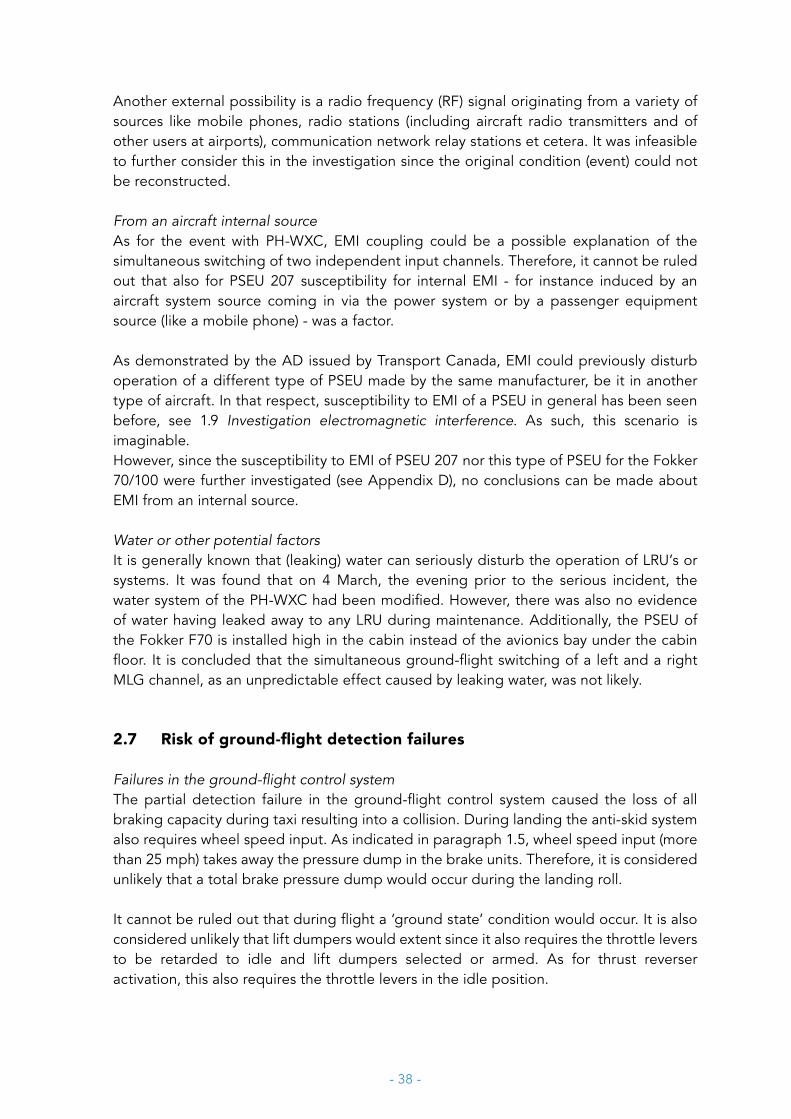
- 38 -
Another external possibility is a radio frequency (RF) signal originating from a variety of sources like mobile phones, radio stations (including aircraft radio transmitters and of other users at airports), communication network relay stations et cetera. It was infeasible to further consider this in the investigation since the original condition (event) could not be reconstructed.
From an aircraft internal sourceAs for the event with PH-WXC, EMI coupling could be a possible explanation of the simultaneous switching of two independent input channels. Therefore, it cannot be ruled out that also for PSEU 207 susceptibility for internal EMI - for instance induced by an aircraft system source coming in via the power system or by a passenger equipment source (like a mobile phone) - was a factor.
As demonstrated by the AD issued by Transport Canada, EMI could previously disturb operation of a different type of PSEU made by the same manufacturer, be it in another type of aircraft. In that respect, susceptibility to EMI of a PSEU in general has been seen before, see 1.9 Investigation electromagnetic interference. As such, this scenario is imaginable.However, since the susceptibility to EMI of PSEU 207 nor this type of PSEU for the Fokker 70/100 were further investigated (see Appendix D), no conclusions can be made about EMI from an internal source.
Water or other potential factors It is generally known that (leaking) water can seriously disturb the operation of LRU’s or systems. It was found that on 4 March, the evening prior to the serious incident, the water system of the PH-WXC had been modified. However, there was also no evidence of water having leaked away to any LRU during maintenance. Additionally, the PSEU of the Fokker F70 is installed high in the cabin instead of the avionics bay under the cabin floor. It is concluded that the simultaneous ground-flight switching of a left and a right MLG channel, as an unpredictable effect caused by leaking water, was not likely.
2.7 Risk of ground-flight detection failures
Failures in the ground-flight control systemThe partial detection failure in the ground-flight control system caused the loss of all braking capacity during taxi resulting into a collision. During landing the anti-skid system also requires wheel speed input. As indicated in paragraph 1.5, wheel speed input (more than 25 mph) takes away the pressure dump in the brake units. Therefore, it is considered unlikely that a total brake pressure dump would occur during the landing roll.
It cannot be ruled out that during flight a ‘ground state’ condition would occur. It is also considered unlikely that lift dumpers would extent since it also requires the throttle levers to be retarded to idle and lift dumpers selected or armed. As for thrust reverser activation, this also requires the throttle levers in the idle position.

- 39 -
Therefore, it is considered unlikely that reverse thrust or lift dumper extension would easily occur in case of incorrect ground state(s) during flight. However, correct state(s) of the ground–flight system is the last barrier to prevent an inadvertent thrust reverser or lift dumper activation by pilots during flight to prevent a possible catastrophic event. Therefore, a properly working ground-flight system remains crucial.
The investigation into the cause of the event with PH-WXC revealed a maintenance environment for avionics equipment in which it remained unclear whether complex failures were solved after a line replaceable unit (LRU) visited a shop for repair. Still, based upon prescribed testing the LRU may be released for service in line with the regulations in force. Though regulations for operators exist to monitor repetitive incidents and unscheduled removals, this process can be further disturbed since LRU’s – exchanged in a pool system - usually do not return to the previous operator which had the failure. In case of a pool system the use of a LRU is usually spread over multiple operators. This may pose a risk to the effectivity of the continued airworthiness when the individual operator cannot keep track of the LRU and its history. In the industry these maintenance practises are rather common for avionics LRU’s and not just typical for PSEU’s.
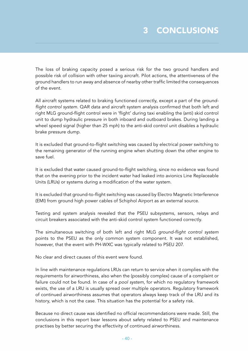
- 40 -
3 CONCLUSIONS
The loss of braking capacity posed a serious risk for the two ground handlers and possible risk of collision with other taxiing aircraft. Pilot actions, the attentiveness of the ground handlers to run away and absence of nearby other traffic limited the consequences of the event.
All aircraft systems related to braking functioned correctly, except a part of the ground-flight control system. QAR data and aircraft system analysis confirmed that both left and right MLG ground-flight control were in ‘flight’ during taxi enabling the (anti) skid control unit to dump hydraulic pressure in both inboard and outboard brakes. During landing a wheel speed signal (higher than 25 mph) to the anti-skid control unit disables a hydraulic brake pressure dump.
It is excluded that ground-to-flight switching was caused by electrical power switching to the remaining generator of the running engine when shutting down the other engine to save fuel.
It is excluded that water caused ground-to-flight switching, since no evidence was found that on the evening prior to the incident water had leaked into avionics Line Replaceable Units (LRUs) or systems during a modification of the water system.
It is excluded that ground-to-flight switching was caused by Electro Magnetic Interference (EMI) from ground high power cables of Schiphol Airport as an external source.
Testing and system analysis revealed that the PSEU subsystems, sensors, relays and circuit breakers associated with the anti-skid control system functioned correctly.
The simultaneous switching of both left and right MLG ground-flight control system points to the PSEU as the only common system component. It was not established, however, that the event with PH-WXC was typically related to PSEU 207. No clear and direct causes of this event were found.
In line with maintenance regulations LRUs can return to service when it complies with the requirements for airworthiness, also when the (possibly complex) cause of a complaint or failure could not be found. In case of a pool system, for which no regulatory framework exists, the use of a LRU is usually spread over multiple operators. Regulatory framework of continued airworthiness assumes that operators always keep track of the LRU and its history, which is not the case. This situation has the potential for a safety risk.
Because no direct cause was identified no official recommendations were made. Still, the conclusions in this report bear lessons about safety related to PSEU and maintenance practises by better securing the effectivity of continued airworthiness.
- 41 -
APPENDIX A
F70 BRAKING SYSTEM
- 42 -
APPENDIX B
GROUND-FLIGHT CONTROLFD
R L
HTA
IL A
NTI
-ICE
THR
US
T R
EV
RIG
HT
(OR
)
SK
ID C
ON
TRO
LO
UTB
OA
RD
THR
US
T R
EV
RIG
HT
(OR
)LI
FT D
UM
PE
RS
(AN
D)
AN
D
THR
US
T R
EV
LE
FT (O
R)
LIFT
DU
MP
ER
S (A
ND
)
OR
FDR
RH
THR
US
T R
EV
LE
FT (O
R)
SK
ID C
ON
TRO
LIN
BO
AR
D
FLIG
HT
WA
RN
ING
CO
MP
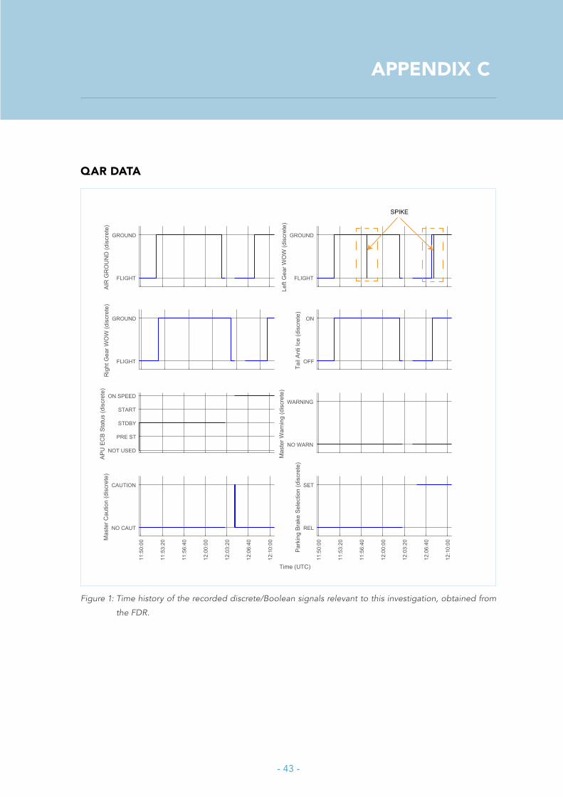
- 43 -
APPENDIX C
QAR DATA
Time (UTC)
11:5
0:00
11:5
3:20
11:5
6:40
12:0
0:00
12:0
3:20
12:0
6:40
12:1
0:00
REL
SET
Park
ing
Brak
e Se
lect
ion
(dis
cret
e)
11:5
0:00
11:5
3:20
11:5
6:40
12:0
0:00
12:0
3:20
12:0
6:40
12:1
0:00
NO CAUT
CAUTION
Mas
ter C
autio
n (d
iscr
ete)
NO WARN
WARNING
Mas
ter W
arni
ng (d
iscr
ete)
NOT USED
PRE ST
STDBY
START
ON SPEED
APU
EC
B St
atus
(dis
cret
e)
OFF
ON
Tail
Anti
Ice
(dis
cret
e)
FLIGHT
GROUND
Rig
ht G
ear W
OW
(dis
cret
e)
FLIGHT
GROUND
Left
Gea
r WO
W (d
iscr
ete)
FLIGHT
GROUND
AIR
GR
OU
ND
(dis
cret
e)
SPIKE
Figure 1: Time history of the recorded discrete/Boolean signals relevant to this investigation, obtained from
the FDR.
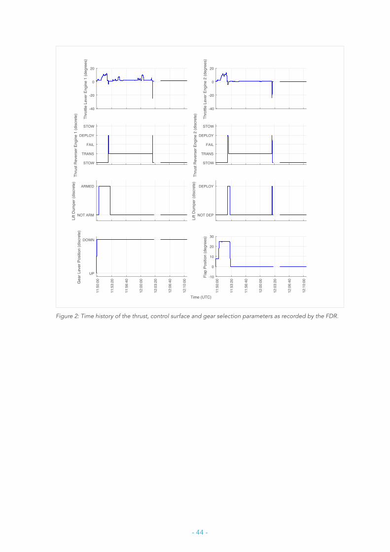
- 44 -
Time (UTC)
11:5
0:00
11:5
3:20
11:5
6:40
12:0
0:00
12:0
3:20
12:0
6:40
12:1
0:00
-10
0
10
20
30
Flap
Pos
ition
(deg
rees
)
11:5
0:00
11:5
3:20
11:5
6:40
12:0
0:00
12:0
3:20
12:0
6:40
12:1
0:00
UP
DOWN
Gea
r Lev
er P
ositi
on (d
iscr
ete)
NOT DEP
DEPLOY
Lift
Dum
per (
disc
rete
)
NOT ARM
ARMED
Lift
Dum
per (
disc
rete
)
STOW
TRANS
FAIL
DEPLOY
STOW
Thru
st R
ever
ser E
ngin
e 2
(dis
cret
e)
STOW
TRANS
FAIL
DEPLOY
STOW
Thru
st R
ever
ser E
ngin
e 1
(dis
cret
e)
-40
-20
0
20
Thro
ttle
Leve
r Eng
ine
2 (d
egre
es)
-40
-20
0
20
Thro
ttle
Leve
r Eng
ine
1 (d
egre
es)
Figure 2: Time history of the thrust, control surface and gear selection parameters as recorded by the FDR.

- 45 -
Time (UTC)
11:5
0:00
11:5
3:20
11:5
6:40
12:0
0:00
12:0
3:20
12:0
6:40
12:1
0:00
0
50
100
150
200
Gro
unds
peed
(kno
ts)
11:5
0:00
11:5
3:20
11:5
6:40
12:0
0:00
12:0
3:20
12:0
6:40
12:1
0:00
0
500
1000
1500
2000
Rad
io H
eigh
t (fe
et)
0
20
40
60
N1
Actu
al E
ngin
e 2
(% rp
m)
0
20
40
60
N1
Actu
al E
ngin
e 1
(% rp
m)
0.8
1
1.2
1.4
Verti
cal A
ccel
erat
ion
(g)
-0.2
-0.1
0
0.1
0.2
Late
ral A
ccel
erat
ion
(g)
-0.2
-0.1
0
0.1
Long
itudi
nal A
ccel
erat
ion
(g)
FLIGHT
GROUNDAI
R G
RO
UN
D (d
iscr
ete)
Figure 3: Time history of the accelerations, engine state, radio altimeter and groundspeed as obtained from
the FDR.

- 46 -
APPENDIX D
LIMITATIONS OF INVESTIGATION
Limitations of the technical investigationDuring the first seven months of the investigation the Dutch Safety Board limited its actions to potential ‘quick wins’ such as the standard testing of the most important components related to the ground-flight system. These components were: the PSEU, ground-flight sensors and relays as far as relevant to the aircraft braking system. Furthermore, the centralised fault display unit (CFDU), which records aircraft system faults for maintenance purposes, was included. However, these ‘quick wins’ did not reveal any causes.
The aircraft maintenance process primarily aims to bring back the aircraft into service for commercial operation. Though the troubleshooting process produced useful information, the gathering of factual information during the first five days after the accident had not been optimally attuned to air safety investigation. This resulted into the necessity to execute additional tests on aircraft in a much later stage of investigation. During the course of investigation Safety Board could rule out EMI coming from an external source. It also appeared that the ground-flight sensors had functioned well during the event.
A more in-depth investigation to better analyse the likelihood of EMI originating from the aircraft itself (internal sources) was estimated to be very complex and comprehensive for every party involved in the investigation. Also, this could not be easily fit into the regular Fokker F70 maintenance schedules of the operator. Based upon the chosen level of investigation, the Dutch Safety Board did not find a direct technical cause which could have explained the ground to flight switching in the PH-WXC.

DUTCHSAFETY BOARD
Visiting address Lange Voorhout 9 2514 EA The HagueT 070 333 70 00 F 070 333 70 77
Postal address PO Box 95404 2509 CK The Hague
www.safetyboard.nl

![REGENERATIVE BRAKING SYSTEM IN ELECTRIC VEHICLES · REGENERATIVE BRAKING SYSTEM IN ELECTRIC VEHICLES ... REGENERATIVE BRAKING SYSTEM ... Regenerative action during braking[9]](https://img.pdfslide.net/doc/110x75/5adccef67f8b9a1a088c7cf0/regenerative-braking-system-in-electric-vehicles-braking-system-in-electric-vehicles.jpg)