Embed Size (px)
Citation preview
Alexandre RademakerVinay K. Chaudhri (Eds.)
FOMI’2014Formal Ontologies meet Industry
6th Workshop on Formal Ontologies meet IndustryWorkshop co-located with 8th International Conference on For-mal Ontology in Information SystemsRio de Janeiro, Brazil, September 22, 2014Proceedings

c©2014 for the individual papers by the papers’ authors. Copying permitted for privateand academic purposes. Re-publication of material from this volume requires permissionby the copyright owners. This volume is published and copyrighted by its editors.
Editors’ addresses:IBM Research Brazil Lab, Rio de Janeiro, BrazilSRI International, CA, USA

Preface
This volume contains the papers presented at FOMI 2014: Sixth Workshop on Founda-tional Ontologies Meet Industry held on September 22nd, 2014 in Rio de Janeiro, Brazil.FOMI is an international forum where academic researchers and industrial practitionersmeet to analyse and discuss application issues related to methods, theories, tools and ap-plications based on formal ontologies.
This volume contains seven peer reviewed articles that were presented at the workshop. Inaddition, the workshop featured an invited talk by Mara Abel on the use of ontologies inthe petroleum industry and a panel discussion.
We thank the authors for their submissions and the program committee for their hard work.
September 2014 Vinay K. ChaudhriAlexandre Rademaker
3

Organizing Committee
Alexandre Rademaker, IBM Research, BrazilVinay K. Chaudhri, SRI International, USA
Program Committee
Adam Pease, IPsoft, USAChris Partridge, Boro Solutions, UKElisa Kendall, Thematix Partners LLC, USAMaira Gatti, IBM Research, Brazil
4
Contents
Representing Organizational Structures in an Enterprise Architecture LanguageDiorbert Pereira and Joao Almeida 7
ISA-88 formalization. A step towards its integration with the ISA-95 standardMarcela Vegetti and Gabriela Henning 17
Improving Ontology Service-Driven Entity DisambiguationPatrice Seyed, Zach Fry and Deborah McGuinness 26
Towards an Ontological Grounding of IFCStefano Borgo, Emilio Sanfilippo, Walter Terkaj and Aleksandra Sojic 36
Ontologies in Enterprise Application: Dimensional ComparisonValeria de Paiva, William Jarrold, David Martin, Peter Patel-Schneider, KarenWallace and Peter Z. Yeh 45
Towards Ontological Support for Principle Solutions in Mechanical EngineeringThilo Breitsprecher, Mihai Codescu, Constantin Jucovschi, Michael Kohlhase, LutzSchorder and Sandro Wartzack 53
5

6
Representing Organizational Structures in an Enterprise
Architecture Language
Diorbert C. PEREIRA
Computer Science Department
Vitória, Brazil
João Paulo A. ALMEIDA
Computer Science Department
Vitória, Brazil
Abstract
Enterprise Architecture (EA) promotes the establishment of a holistic view
of the structure and way of working of an organization. One of the aspects
covered in EA is associated with the organization’s “active structure”,
which concerns “who” undertakes organizational activities. Several
approaches have been proposed in order to provide a means for
representing enterprise architectures, among which the ArchiMate, an EA
modeling language. In this paper, we present a semantic analysis of the
fragment of the ArchiMate metamodel related with the representation of
active structure. In addition, we present a proposal to extend the metamodel
based on a well-founded ontology for the organizational domain. Our
objective is to enrich the language with important capabilities to represent
organizational structures using a principled ontology-based approach.
Introduction
Enterprise Architecture (EA) promotes the establishment of a holistic view of the organization in order to provide
organizations with the ability to understand its structure and way of working. As defined in [1], the description of an EA
usually “takes the form of a comprehensive set of cohesive models that describe the structure and functions of an
enterprise”. The majority of EA frameworks considers an organization as a system whose elements include: (i)
organizational activities structured in business processes and services; (ii) information systems supporting organizational
activities; (iii) underlying information technology (IT) infrastructures, and (iv) organizational structures (organizational
actors, roles and organizational units).
This last domain of elements is also called “active structure” [2] and concerns “who” undertakes organizational
activities. Active structure focuses on the business agents that perform tasks and seek to achieve goals, encompassing the
definition of business roles, authority relationships, communication lines, work groups, etc. The relevance of
organizational structure is clear from a management perspective in that it defines authority and responsibility relations
between the various elements of an enterprise. Further, from the perspective of enterprise information systems,
organizational actors can be considered as system owners, system maintainers, system users or simply system
stakeholders in general, affecting the usage and evolution of such systems [3]. Our ultimate goal is to produce EA
models that represent organizational reality faithfully and thus serve for the purposes of EA documentation, analysis and
communication.
In this paper, we are particularly interested in the modeling of the active structure domain in the widely employed EA
modeling language ArchiMate [2]. A strength of this language is the broad coverage of a wide number of aspects of EA,
and the possibility to describe relations between the various aspects. Nevertheless, the emphasis on providing an
overview of relations seem to have led to a less sophisticated treatment of some aspects, and that includes the active
7
structure domain. As a consequence, some shortcomings have been identified by the ontology community [4][5], such as
limitations on its conceptual coverage and lack of clear real-world semantics for some of its constructs. The limitations
in the coverage of concepts affect the language’s ability to represent important organizational phenomena (affecting
expressiveness, or what is called “completeness” in [6]). The absence of a well-defined real-world semantics opens space
for interpretations not originally intended by a language user, resulting in ambiguous and inaccurate representations and
ultimately in problems of communication between users.
Our primary goal is to address these limitations by proposing means to represent more sophisticated organizational
structures in ArchiMate. We address this task with a principled approach. We first define a reference ontology for the
active structure domain. Our objective for this reference ontology is to focus on core aspects of this domain in
accordance with dominant themes in the management literature. Having this reference ontology enables us to analyze the
capacity of ArchiMate to represent information about the active structure domain. We point out the problems and their
consequences for the generation of high-quality EA models. Finally, we present a proposal to extend the language
metamodel to address the identified issues and contribute to the increase of the expressiveness and clarity of the
language.
This paper is structured as follows: Section 1 reviews basic organizational concepts in order to set minimum
requirements for the representation of the active structure of organizations. Section 2 introduces the OntoUML Org
Ontology (O3). Section 3 introduces ArchiMate active structure constructs briefly. Section 4 the analysis and revision of
ArchiMate using the notions of O3. Section 5 discusses related work. Finally, Section 6 presents our conclusions.
1 Basic Notions in the Organizational Literature
In the organizational literature, some basic organizational notions are frequently referred to in order to characterize
organizations. In this section, we discuss these notions, as they form basic requirements of expressiveness of
organizational structure. We do not aim at exhausting all relevant aspects concerning organizational structure. We focus
on three dominant themes in the management literature: (i) division of labor, (ii) social relations and (iii) types of
structuring units.
1.1 Division of Labor
We, as human beings, have limitations on processing information and on accomplishing tasks [7]. Division of labor
manages our human limitations and coordinates us to achieve organizational goals. Fayol defined in [8] that the division
of labor aims to produce more and better, with the same effort, in addition to reducing the number of objectives upon
which the attention and effort should be applied.
In a top-down view, organizations can be considered as systems composed of subsystems, each of which can be
nested into subsystems recursively [9]. Division of labor consists in the top-down view of dividing an overarching
organizational mission into specialized goals or tasks allocated to distinct well-defined units of work in order to increase
efficiency. The creation of working groups aggregating individuals with heterogeneous skills that pursue a common
purpose represents the definition of these subsystems (which we will call here Organizational Units). In a bottom-up
view, “we are confronted by the task of analyzing everything that has to be done and determining in what grouping it can
be placed […] Workers may be easily combined in a single aggregate and supervised together” [10].
The division of labor in its highest degree of specialization is represented by defining “positions”. At this level of
granularity, the tasks are distributed among the various positions as official duties. This infers a clear division of labor
between positions, as defined in [11]. Positions also allow the formalization of the organization based on descriptions of
duties, rights, requirements and social relations assigned to reusable organizational roles and not directly on the actors
who play them.
1.2 Social Relations
Within the universe of a formal organization, social relations of power and communication are of great relevance.
Concerning power relations, [8] defines that authority is the right to command and the power to be obeyed. Without
authority, i.e., without explicit formal organization in upper and lower positions, where the superiors have more power
than the lower, the organization ceases to be a coordinated entity [12]1. Apart from power relations, communication
relations allow the definition of interactions between business actors without requiring the establishment of relations of
authority. The existence of a relationship of authority between organizational actors implies the existence of a
relationship of communication between them, but the contrary is not always true.
1 This reveals our interest specifically in organizations that are, to a certain extent, hierarchical
Representing Organizational Structures in an Enterprise Architecture Language
8
1.3 Types of Structuring Units
The working groups that compose organizations have different natures. Different structuring principles (functional, line-
staff, divisional, matrix and flat organizations) lead to different types of structuring units like departments, divisions, line
units, staff units, teams and task forces.
In organizations structured following the line-staff model, one of the main distinctions is between line and staff units.
The line units comprise the functional organization and represent the specialization of division of labor in
functional/production units following different criteria of aggregation of individuals. The line units can relate through
relationships of authority and are composed of other line units [13]. In contrast, staff units are units without
administrative authority, who have the responsibility of advising the production units to perform actions and do not have
full responsibility for the execution of tasks [14]. The “staff authority is subordinate to line authority, and they tend to
identify line with managers or administrators and staff with experts and specialists” [14].
Other types of working groups present in organizations that adopt the matrix model are the teams and task forces [15],
which are units with dual authority relationship, where the relationship of power is balanced between formal authority
and technical authority [15]. Teams and task forces aggregate employees belonging to different
departments/divisions/line units and can have limited lifetime. In addition, these types of structuring units put together in
a single unit the authority and information necessary for performing tasks [15]. The main difference between teams and
task forces lies in the fact that task forces are used to solve temporary problems, while teams are used to solve recurring
problems [15].
2 The Reference Domain Ontology
The basis of the semantic analysis of ArchiMate performed in this paper is a reference domain ontology which we call
OntoUML Org Ontology (O3). It covers the organizational domain, focusing on the themes discussed in the previous
section. In order to represent this reference ontology, we employ OntoUML, a UML profile that incorporates the
foundational distinctions of the Unified Foundational Ontology (UFO) using UML stereotypes. Thus, our domain
ontology employs and specializes the more general domain-independent notions of objects, types, events, social entities,
etc. (A brief description of the required UFO concepts is given below in sections 2.1 and 2.2. See [6] and [16] for
thorough presentations.) Our choice for UFO is based on the key role it has played in previous efforts in domain
ontology engineering [16], harmonization of semantic models [17][18] and evaluation and revision of enterprise
languages [3][19]. By specializing UFO, O3 provides an ontologically well-grounded view that covers the basic notions
of the organizational domain.
2.1 Basic Entities
We start with the basic distinction in UFO between Individuals and Universals. Individuals are entities that exist in
reality instantiating one or more universals and possessing a unique identity. Universals (more specifically first-order
universals) are patterns of features that can be realized in a number of individuals. Roughly speaking, individuals can be
viewed as elements and first-order universals as their types.
Substantials are individuals that do not need others individuals to exist, i.e., are existentially independent (e.g., a car,
an apple, Bill Gates). Moments are particularized properties inherent to an individual and are existentially dependent on
the individuals on which they inhere. Moments can be intrinsic or relational. Intrinsic moments apply to a single subject
(e.g., an apple’s color, someone’s headache). Relational moments are called relators and depend on various relata (e.g.,
an employment contract relating an employee and an employer, a marriage contract between husband and wife) [6].
The stereotypes in OntoUML correspond to ontological distinctions for universals of UFO, enabling us to use class
diagrams to represent ontologies that employ the distinctions of UFO. For instance, a class stereotyped as <<category>>
represents a rigid concept, i.e., a class that applies necessarily to its instances (throughout their entire existence). A class
stereotyped as <<kind>> also represents a rigid concept but one that supplies a principle of identity to its instances (e.g.,
Person). A class stereotyped as <<role>> (or <<role mixin>>), in turn, is an anti-rigid concept, applying contingently to
its instances (e.g., a Person is only an Employee contingently and can cease to play that role and still exist). A role is also
relational dependent, i.e., it defines contingent properties exhibited by an entity in the scope of a relationship (when an
individual instantiates a role universal, it is thus connected to at least one other individual through a relator).
2.2 Intentional and Social Aspects
UFO includes a social layer that specializes its core with distinctions to account for intentionality and social reality [16].
An important distinction in this layer is that between agentive and non-agentive objects. Agentive objects (agents) can
perform actions and have mental/intentional moments (intentions, desires and beliefs). Agents are differentiated in
Representing Organizational Structures in an Enterprise Architecture Language
9
physical agents (e.g., a person) and social agents (e.g., an organization). Objects are passive entities that can be used,
consumed, destructed, modified and created by agents. Objects are partitioned into physical objects (e.g., a computer, a
pen) and social objects (e.g., a piece of legislation, a language).
Normative descriptions are social objects that define rules/norms recognized by agents. Normative descriptions can
define nominal universals, such as social objects (e.g., the crown of the King of Spain) and social roles (e.g., IT Analyst,
surgeon).
2.3 OntoUML Org Ontology (O3)
O3 has been defined by extending the social concepts of UFO, such as social role, social agent and physical agent. In this
paper we present fragments of O3 focusing on the concepts required for the purpose of this paper, namely, the analysis
and revision of the ArchiMate active structure elements. We discuss the ontology following two points of view: (i)
organizational structure (section 2.3.1) and (ii) roles (section 2.3.2).
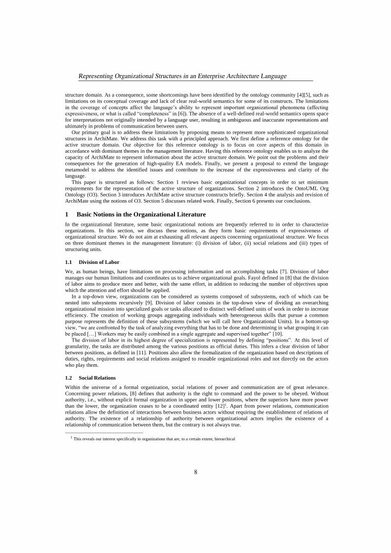
2.3.1 Organizational Structure
Figure 1 presents the fragment of O3 related with the organizational structure concepts. The top-most concept is
organization, specializing the UFO notion of Social Agent. As defined in [12], organizations are (artificial) social units
built with the explicit intention of pursuing specific goals. In another definition, organizations are defined as
"collectivities that have been established for the pursuit of relatively specific objectives on a more or less continuous
basis" [20]. Human resources are among the major means used by organizations to achieve its goals [12]. In healthy
organizations, the organizational goals are assimilated by its human resources in combination with its personal goals.
Organizations include corporations, armies, hospitals and churches, but exclude tribes, ethnic groups, families and
groups of friends. Organizations are characterized by division of labor, presence of one or more power centers that
control the combined efforts of the organization and coordinate activities to achieve goals. Members of an organization
can be replaced or relocated to other functions without the organization ceasing to exist. An organization may be
structured into other social agents that together contribute to the operation or behavior of the whole, defining thus what is
called a functional complex in [6]. (See [19] for a discussion on the whole-part relation of UFO applied at the
organizational context.)
We specialize organizations into formal organizations and organizational units. Formal organizations are formally
recognized by the external environment. Their creation is determined by normative descriptions or speech acts which are
recognized by the normative context in which formal organizations exist. Examples of formal organization include
Microsoft Inc., the UK Government and the Fed. University of Espírito Santo.
Organizational units are those organizations that are only recognized in the internal context of a formal organization
and represent the working groups of a formal organization. An organizational unit can be a structural unit or a missionary
unit. Structural units are closely related to functional structure of the organization, including line units and staff units. A
line unit has authority relationships with other line units (upper or lower). Such relationships result in a hierarchy of
authority. Furthermore, it may be composed of other line units, resulting in a relationship of authority (represented by the
relationship “manages”) between parts. The justification for the structuring of line units through two distinct
relationships (whole-part and authority) lies in the fact that the whole-part relationship (in the organizational domain)
naturally implies power, but power does not imply a whole-part relation. Examples of line unit include a Marketing
Department, a Board of Directors and a Sales Division. As seen in Section 1, a staff unit is a “counselor” unit, which has
no administrative authority, thus it is not part of line hierarchy composed by line units. Although they have no line
authority, staff units relate to line units through the relation “staff of”, which determines the line unit to which a staff unit
responds. Examples of staff unit: a Group of Financial Advisors and an Internal Audit Group. Missionary units represent
teams and task forces related to the matrix structure of the formal organization, such as a project group and a task force
to deliver a product to the market in the schedule. A feature of this type of work group is the aggregation of actors
belonging to different line units. Examples of missionary unit include an ERP Project Team, an Audit Committee and a
Financial Task Force.
Representing Organizational Structures in an Enterprise Architecture Language
10
Figure 1: Fragment of OntoUML Org Ontology related with organizational structure.
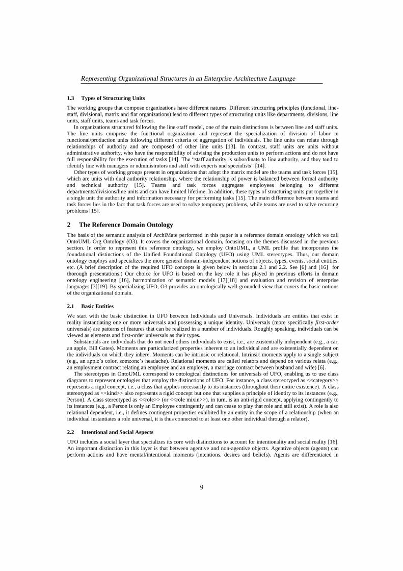
2.3.2 Organizational Roles
Figure 2 presents the concepts related with the agents that compose the organization and the types of roles they may
play. We are concerned in this fragment with the roles persons play, first of all as a member of a formal organization
(formal organization member), and then when they are given more specific places in the power structure, either in a
structural (line or staff) unit (structural unit member) or in missionary units (missionary unit member). (For the sake of
brevity the diagram omits the <<relator>> classes that connect the individuals playing the roles and the formal
organization, structural and missionary units.) Note that in order to play a particular role in an organizational unit, a
person needs to be a formal organization member first.
In the scope of each organization, different specializations of these more general roles are required. For example, in a
university, employee types such as “Professor” and “Secretary” become relevant, while in a hospital employee types
such as “Doctor” and “Nurse” may be defined. Therefore, O3 includes the second-order notions of employee type and
other business roles. They are to be instantiated in particular settings creating thus specific roles. The instances of
employee type specialize formal organization member, and the instances of business role specialize either structural unit
member or missionary unit member. We represent them by following UML’s “powertype” representation pattern with
the second-order concept stereotyped <<hou>> (for higher-order universal), highlighted in gray. Specific employee types
define the set of roles (business roles) that a typified employee can occupy in the organization (see “cover” relationship).
Business roles defines more specific capabilities, duties and prerogatives possibly in the scope of organizational units.
An employee allocated to a structural unit plays a structural business role; employees assigned to missionary units play
missionary business roles. Authority relations between these types of business roles can be define through the
relationships “is superior to”.
Representing Organizational Structures in an Enterprise Architecture Language
11
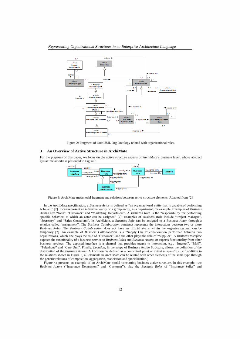
Figure 2: Fragment of OntoUML Org Ontology related with organizational roles.
3 An Overview of Active Structure in ArchiMate
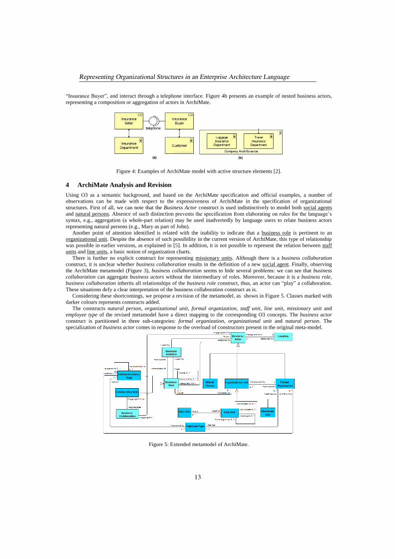
For the purposes of this paper, we focus on the active structure aspects of ArchiMate’s business layer, whose abstract
syntax metamodel is presented in Figure 3.
Figure 3: ArchiMate metamodel fragment and relations between active structure elements. Adapted from [2].
In the ArchiMate specification, a Business Actor is defined as “an organizational entity that is capable of performing
behavior” [2]. It can represent an individual entity or a group entity, as a department, for example. Examples of Business
Actors are: “John”, “Customer” and “Marketing Department”. A Business Role is the “responsibility for performing
specific behavior, to which an actor can be assigned” [2]. Examples of Business Role include “Project Manager”,
“Secretary” and “Sales Consultant”. In ArchiMate, a Business Role can be assigned to a Business Actor through a
relation called “assignment”. The Business Collaboration construct represents the interactions between two or more
Business Roles. The Business Collaboration does not have an official status within the organization and can be
temporary [2]. An example of Business Collaboration is a “Supply Chain” collaboration performed between two
organizations, which one plays the role of “Customer”, and the other plays the role of “Supplier”. A Business Interface
exposes the functionality of a business service to Business Roles and Business Actors, or expects functionality from other
business services. The exposed interface is a channel that provides means to interaction, e.g., “Internet”, “Mail”,
“Telephone” and “Care Unit”. Finally, Location, in the scope of Business Active Structure, allows the definition of the
distribution of the Business Actors. A Location “is defined as a conceptual point or extent in space” [2]. (In addition to
the relations shown in Figure 3, all elements in ArchiMate can be related with other elements of the same type through
the generic relations of composition, aggregation, association and specialization.)
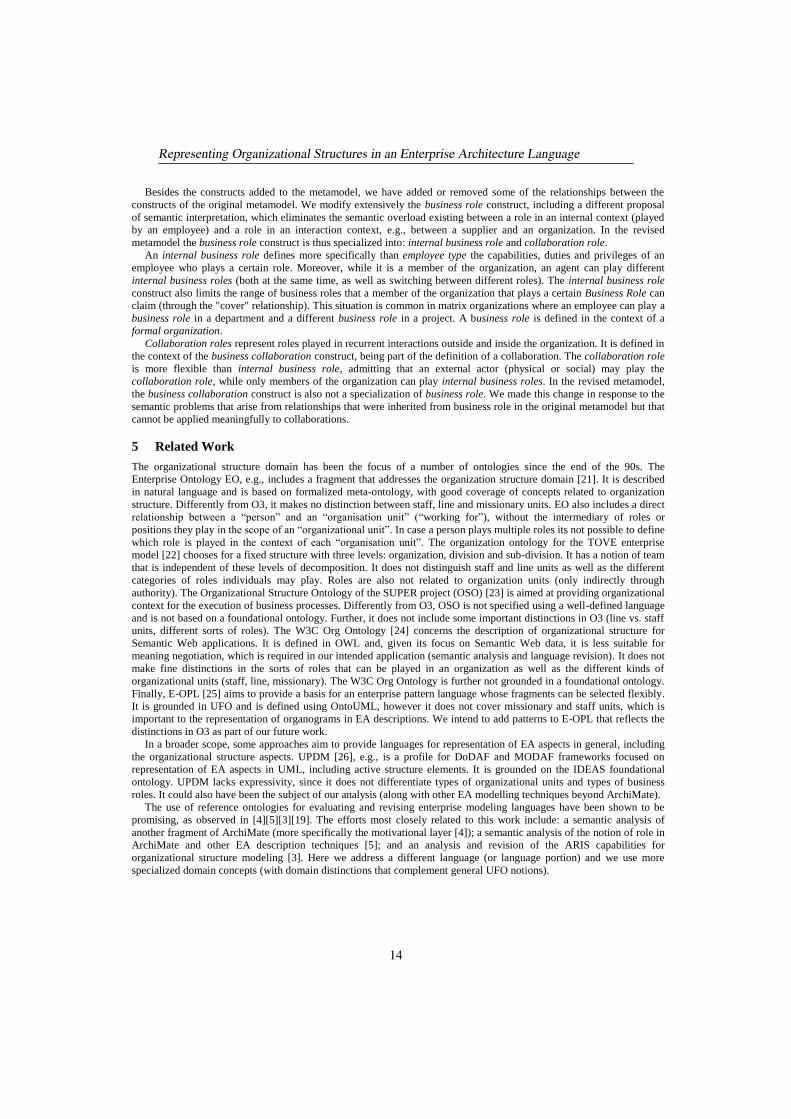
Figure 4a presents an example of an ArchiMate model concerning business active structure. In this example, two
Business Actors (“Insurance Department” and “Customer”), play the Business Roles of “Insurance Seller” and
Representing Organizational Structures in an Enterprise Architecture Language
12
“Insurance Buyer”, and interact through a telephone interface. Figure 4b presents an example of nested business actors,
representing a composition or aggregation of actors in ArchiMate.
Figure 4: Examples of ArchiMate model with active structure elements [2].
4 ArchiMate Analysis and Revision
Using O3 as a semantic background, and based on the ArchiMate specification and official examples, a number of
observations can be made with respect to the expressiveness of ArchiMate in the specification of organizational
structures. First of all, we can note that the Business Actor construct is used indistinctively to model both social agents
and natural persons. Absence of such distinction prevents the specification from elaborating on rules for the language’s
syntax, e.g., aggregation (a whole-part relation) may be used inadvertedly by language users to relate business actors
representing natural persons (e.g., Mary as part of John).
Another point of attention identified is related with the inability to indicate that a business role is pertinent to an
organizational unit. Despite the absence of such possibility in the current version of ArchiMate, this type of relationship
was possible in earlier versions, as explained in [5]. In addition, it is not possible to represent the relation between staff
units and line units, a basic notion of organization charts.
There is further no explicit construct for representing missionary units. Although there is a business collaboration
construct, it is unclear whether business collaboration results in the definition of a new social agent. Finally, observing
the ArchiMate metamodel (Figure 3), business collaboration seems to hide several problems: we can see that business
collaboration can aggregate business actors without the intermediary of roles. Moreover, because it is a business role,
business collaboration inherits all relationships of the business role construct, thus, an actor can “play” a collaboration.
These situations defy a clear interpretation of the business collaboration construct as is.
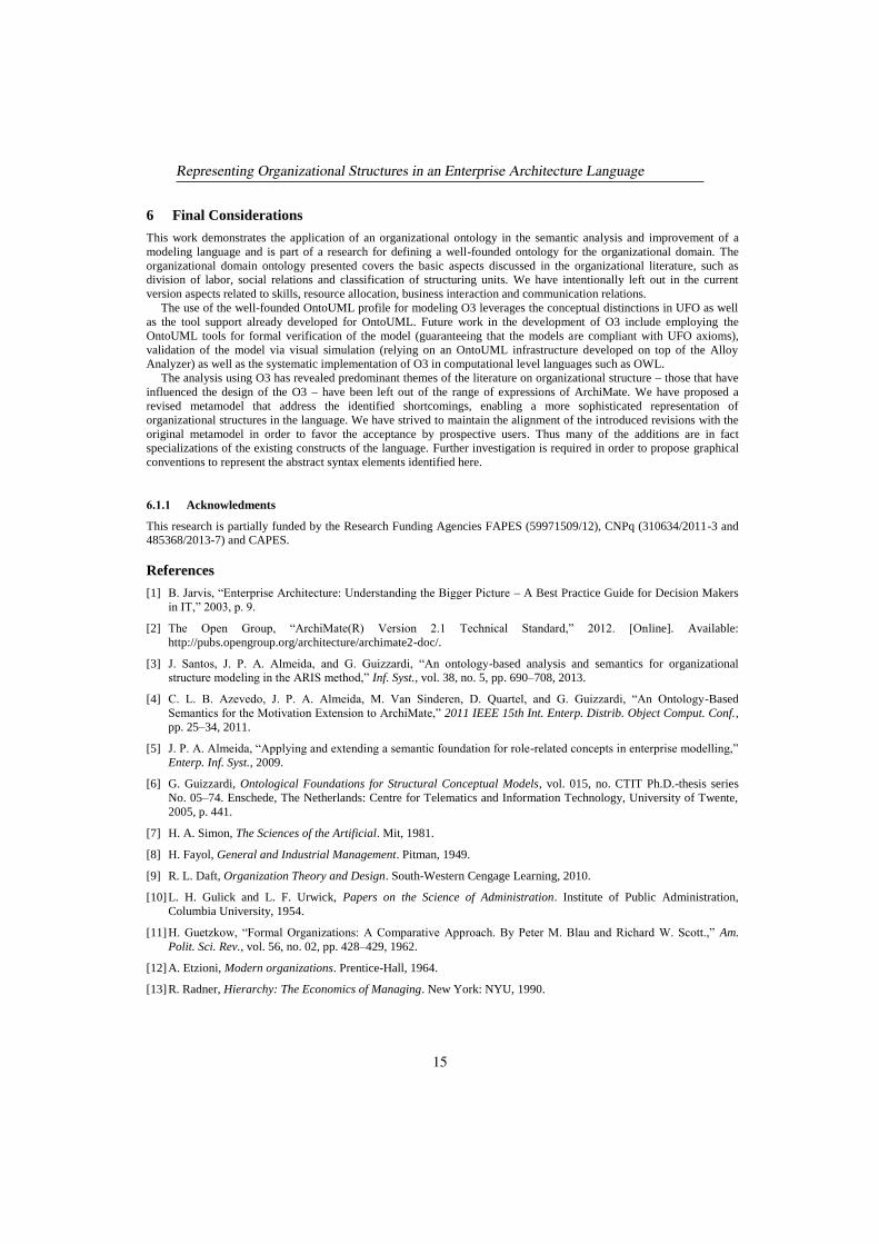
Considering these shortcomings, we propose a revision of the metamodel, as shown in Figure 5. Classes marked with
darker colours represents constructs added.
The constructs natural person, organizational unit, formal organization, staff unit, line unit, missionary unit and
employee type of the revised metamodel have a direct mapping to the corresponding O3 concepts. The business actor
construct is partitioned in three sub-categories: formal organization, organizational unit and natural person. The
specialization of business actor comes in response to the overload of constructors present in the original meta-model.
Figure 5: Extended metamodel of ArchiMate.
Representing Organizational Structures in an Enterprise Architecture Language
13
Besides the constructs added to the metamodel, we have added or removed some of the relationships between the
constructs of the original metamodel. We modify extensively the business role construct, including a different proposal
of semantic interpretation, which eliminates the semantic overload existing between a role in an internal context (played
by an employee) and a role in an interaction context, e.g., between a supplier and an organization. In the revised
metamodel the business role construct is thus specialized into: internal business role and collaboration role.
An internal business role defines more specifically than employee type the capabilities, duties and privileges of an
employee who plays a certain role. Moreover, while it is a member of the organization, an agent can play different
internal business roles (both at the same time, as well as switching between different roles). The internal business role
construct also limits the range of business roles that a member of the organization that plays a certain Business Role can
claim (through the "cover" relationship). This situation is common in matrix organizations where an employee can play a
business role in a department and a different business role in a project. A business role is defined in the context of a
formal organization.
Collaboration roles represent roles played in recurrent interactions outside and inside the organization. It is defined in
the context of the business collaboration construct, being part of the definition of a collaboration. The collaboration role
is more flexible than internal business role, admitting that an external actor (physical or social) may play the
collaboration role, while only members of the organization can play internal business roles. In the revised metamodel,
the business collaboration construct is also not a specialization of business role. We made this change in response to the
semantic problems that arise from relationships that were inherited from business role in the original metamodel but that
cannot be applied meaningfully to collaborations.
5 Related Work
The organizational structure domain has been the focus of a number of ontologies since the end of the 90s. The
Enterprise Ontology EO, e.g., includes a fragment that addresses the organization structure domain [21]. It is described
in natural language and is based on formalized meta-ontology, with good coverage of concepts related to organization
structure. Differently from O3, it makes no distinction between staff, line and missionary units. EO also includes a direct
relationship between a “person” and an “organisation unit” (“working for”), without the intermediary of roles or
positions they play in the scope of an “organizational unit”. In case a person plays multiple roles its not possible to define
which role is played in the context of each “organisation unit”. The organization ontology for the TOVE enterprise
model [22] chooses for a fixed structure with three levels: organization, division and sub-division. It has a notion of team
that is independent of these levels of decomposition. It does not distinguish staff and line units as well as the different
categories of roles individuals may play. Roles are also not related to organization units (only indirectly through
authority). The Organizational Structure Ontology of the SUPER project (OSO) [23] is aimed at providing organizational
context for the execution of business processes. Differently from O3, OSO is not specified using a well-defined language
and is not based on a foundational ontology. Further, it does not include some important distinctions in O3 (line vs. staff
units, different sorts of roles). The W3C Org Ontology [24] concerns the description of organizational structure for
Semantic Web applications. It is defined in OWL and, given its focus on Semantic Web data, it is less suitable for
meaning negotiation, which is required in our intended application (semantic analysis and language revision). It does not
make fine distinctions in the sorts of roles that can be played in an organization as well as the different kinds of
organizational units (staff, line, missionary). The W3C Org Ontology is further not grounded in a foundational ontology.
Finally, E-OPL [25] aims to provide a basis for an enterprise pattern language whose fragments can be selected flexibly.
It is grounded in UFO and is defined using OntoUML, however it does not cover missionary and staff units, which is
important to the representation of organograms in EA descriptions. We intend to add patterns to E-OPL that reflects the
distinctions in O3 as part of our future work.
In a broader scope, some approaches aim to provide languages for representation of EA aspects in general, including
the organizational structure aspects. UPDM [26], e.g., is a profile for DoDAF and MODAF frameworks focused on
representation of EA aspects in UML, including active structure elements. It is grounded on the IDEAS foundational
ontology. UPDM lacks expressivity, since it does not differentiate types of organizational units and types of business
roles. It could also have been the subject of our analysis (along with other EA modelling techniques beyond ArchiMate).
The use of reference ontologies for evaluating and revising enterprise modeling languages have been shown to be
promising, as observed in [4][5][3][19]. The efforts most closely related to this work include: a semantic analysis of
another fragment of ArchiMate (more specifically the motivational layer [4]); a semantic analysis of the notion of role in
ArchiMate and other EA description techniques [5]; and an analysis and revision of the ARIS capabilities for
organizational structure modeling [3]. Here we address a different language (or language portion) and we use more
specialized domain concepts (with domain distinctions that complement general UFO notions).
Representing Organizational Structures in an Enterprise Architecture Language
14
6 Final Considerations
This work demonstrates the application of an organizational ontology in the semantic analysis and improvement of a
modeling language and is part of a research for defining a well-founded ontology for the organizational domain. The
organizational domain ontology presented covers the basic aspects discussed in the organizational literature, such as
division of labor, social relations and classification of structuring units. We have intentionally left out in the current
version aspects related to skills, resource allocation, business interaction and communication relations.
The use of the well-founded OntoUML profile for modeling O3 leverages the conceptual distinctions in UFO as well
as the tool support already developed for OntoUML. Future work in the development of O3 include employing the
OntoUML tools for formal verification of the model (guaranteeing that the models are compliant with UFO axioms),
validation of the model via visual simulation (relying on an OntoUML infrastructure developed on top of the Alloy
Analyzer) as well as the systematic implementation of O3 in computational level languages such as OWL.
The analysis using O3 has revealed predominant themes of the literature on organizational structure – those that have
influenced the design of the O3 – have been left out of the range of expressions of ArchiMate. We have proposed a
revised metamodel that address the identified shortcomings, enabling a more sophisticated representation of
organizational structures in the language. We have strived to maintain the alignment of the introduced revisions with the
original metamodel in order to favor the acceptance by prospective users. Thus many of the additions are in fact
specializations of the existing constructs of the language. Further investigation is required in order to propose graphical
conventions to represent the abstract syntax elements identified here.
6.1.1 Acknowledments
This research is partially funded by the Research Funding Agencies FAPES (59971509/12), CNPq (310634/2011-3 and
485368/2013-7) and CAPES.
References
[1] B. Jarvis, “Enterprise Architecture: Understanding the Bigger Picture – A Best Practice Guide for Decision Makers
in IT,” 2003, p. 9.
[2] The Open Group, “ArchiMate(R) Version 2.1 Technical Standard,” 2012. [Online]. Available:
http://pubs.opengroup.org/architecture/archimate2-doc/.
[3] J. Santos, J. P. A. Almeida, and G. Guizzardi, “An ontology-based analysis and semantics for organizational
structure modeling in the ARIS method,” Inf. Syst., vol. 38, no. 5, pp. 690–708, 2013.
[4] C. L. B. Azevedo, J. P. A. Almeida, M. Van Sinderen, D. Quartel, and G. Guizzardi, “An Ontology-Based
Semantics for the Motivation Extension to ArchiMate,” 2011 IEEE 15th Int. Enterp. Distrib. Object Comput. Conf.,
pp. 25–34, 2011.
[5] J. P. A. Almeida, “Applying and extending a semantic foundation for role-related concepts in enterprise modelling,”
Enterp. Inf. Syst., 2009.
[6] G. Guizzardi, Ontological Foundations for Structural Conceptual Models, vol. 015, no. CTIT Ph.D.-thesis series
No. 05–74. Enschede, The Netherlands: Centre for Telematics and Information Technology, University of Twente,
2005, p. 441.
[7] H. A. Simon, The Sciences of the Artificial. Mit, 1981.
[8] H. Fayol, General and Industrial Management. Pitman, 1949.
[9] R. L. Daft, Organization Theory and Design. South-Western Cengage Learning, 2010.
[10] L. H. Gulick and L. F. Urwick, Papers on the Science of Administration. Institute of Public Administration,
Columbia University, 1954.
[11] H. Guetzkow, “Formal Organizations: A Comparative Approach. By Peter M. Blau and Richard W. Scott.,” Am.
Polit. Sci. Rev., vol. 56, no. 02, pp. 428–429, 1962.
[12] A. Etzioni, Modern organizations. Prentice-Hall, 1964.
[13] R. Radner, Hierarchy: The Economics of Managing. New York: NYU, 1990.
Representing Organizational Structures in an Enterprise Architecture Language
15
[14] A. Etzioni, Authority Structure and Organizational Effectiveness, Vol. 4. Administrative Science Quarterly, 1959.
[15] J. R. Galbraith, Matrix Organization Designs: How to Combine Functional and Project Forms. 1971.
[16] G. Guizzardi, R. Falbo, and R. S. S. Guizzardi, “Grounding Software Domain Ontologies in the Unified
Foundational Ontology ( UFO ): The case of the ODE Software Process Ontology,” Softw., no. i, 2008.
[17] J. P. A. Almeida, E. C. S. Cardoso, and G. Guizzardi, “On the Goal Domain in the RM-ODP Enterprise Language:
An Initial Appraisal Based on a Foundational Ontology,” EDOCW, pp. 382–390, 2010.
[18] E. Cardoso, P. S. Santos, J. P. A. Almeida, R. Guizzardi, and G. Guizzardi, “Semantic Integration of Goal and
Business Process Modeling,” in CONFENIS, 2010, no. 45444080.
[19] J. P. A. Almeida and G. Guizzardi, “An ontological analysis of the notion of community in the RM-ODP enterprise
language,” Comput. Stand. Interfaces, vol. 35, no. 3, pp. 257–268, Mar. 2013.
[20] W. R. Scott, “Theory of Organisations,” in Handbook Of Modern Sociology, Robert E.L. Faris, Ed. Chicago: Paul
McNally and Corp., 1964.
[21] M. Uschold, M. King, S. Moralee, and Y. Zorgios, “Enterprise Ontology specification,” 1998. [Online]. Available:
http://www.aiai.ed.ac.uk/project/enterprise/enterprise/ontology.html.
[22] M. S. Fox, M. Barbuceanu, M. Gruninger, and J. Lin, “Simulating Organizations,” M. J. Prietula, K. M. Carley, and
L. Gasser, Eds. Cambridge, MA, USA: MIT Press, 1998, pp. 131–152.
[23] W. Abramowicz, A. Filipowska, et al, “Organization Structure Description for the Needs of Semantic Business
Process Management,” 3rd Int. Work. Semant. Bus. Process Manag., 2008.
[24] W3C, “Org Ontology specification,” 2014. [Online]. Available: http://www.w3.org/TR/2014/REC-vocab-org-
20140116/.
[25] R. de A. Falbo, F. B. Ruy, G. Guizzardi, M. P. Barcellos, and J. P. A. Almeida, “Towards an Enterprise Ontology
Pattern Language,” in Proc. 29th Annual ACM Symp. Applied Comp., 2014, pp. 323–330.
[26] OMG, “UPDM specification,” 2014. [Online]. Available: http://www.omg.org/spec/UPDM/.
Representing Organizational Structures in an Enterprise Architecture Language
16
ISA-88 Formalization. A Step Towards its Integration with the ISA-
95 Standard
Marcela Vegetti Gabriela Henning
INGAR (CONICET-UTN) INTEC (CONICET-UTN)
[email protected] [email protected]
Abstract.
ANSI/ISA-88 and ANSI/ISA-95 are two well accepted standards in the industrial domain that
provide a set of models considered as best engineering practices for industrial information
systems in charge of manufacturing execution and business logistics. The main goal of
ANSI/ISA-88 is the control of batch processes, whereas the one of the ANSI/ISA-95 standard
is the development of an automated interface between enterprise and control systems. In
consequence, both standards should interoperate. However, there are gaps and overlappings
between their corresponding terminologies. Moreover, there are additional problems, such as
semantic inconsistencies within each of the standards, as well as the use of an informal
graphical representations in one of the ANSI/ISA-88 models. This work presents an
ontological approach that aims at formalizing the ISA-88 standard as a first step towards its
integration with a formal representation of the ANSI/ISA-95 one. Additionally,
methodological aspects of the ontology development process are presented.
1 Introduction
Industrial organizations address their planning activities within the context of the enterprise hierarchical planning pyramid. This pyramid (see Figure 1) includes activities performed at different time frames, handles information having distinct granularities, and involves scheduling interplaying with the Production Planning and Control (PPC) and Plant Control (PC) functions. The difficulties associated with these interactions were pointed out almost a decade ago [Sho02] and this topic has recently gained renewed attention. To tackle the integration of PPC and scheduling, researchers have proposed various solution strategies [Mar09]. In addition, a few authors have pointed out the requirements that apply to the data exchange in order to support such integration [Kre06]. Similarly, regarding integration between scheduling and plant control, researchers have started to draw the attention to data exchange problems [Mun10], [Har09]. Moreover, the standards ANSI/ISA-88 [Ans10] and ANSI/ISA-95 [Ans00] (referred as ISA-88 and ISA-95 for simplicity reasons) have been developed to tackle issues related to planning, scheduling and control activities and data. Whereas both standards address the exchange of data between the scheduling function and its immediate upper and lower levels in the planning pyramid, a more comprehensive approach is required to address integration problems, since this matter entails much more than data exchange.
The aforementioned problems are related with semantic issues, which constitute challenges that should be addressed to reach a semantic integration of enterprise applications. For example, the batch concept has three definitions in ISA-88. This term is used as an abstract contraction of the words "the production of a batch"[Ans10]. Therefore, according to the context, batch means both the material made by and during the process and also an entity that represents the production of that material. In a similar way, the terms procedure and recipe component have different meanings within the ISA-88 standard. The opposite situation, more than one term to represent a given concept, also occurs between the ISA-88 and ISA-95 standards. Both use different terms to define concepts such as "amount of material", "equipment", "group of products scheduled to be manufactured" and "how to make a product". Moreover, ISA-88 lacks a formalism to represent the procedural part of a recipe, since it employs an informal graphical model
1
Copyright by the paper's authors. Copying permitted for private and academic purposes.
In: Alexandre Rademaker and Vinay K. Chaudhri (eds.): Proceedings of the 6th Workshop on Formal Ontologies meet Industry, Rio de Janeiro, Brazil, 22-SEP-2014, published at http://ceur-ws.org
17
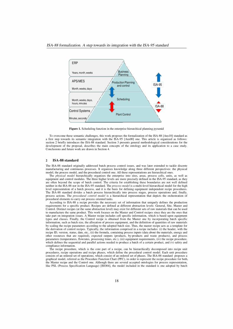
Figure 1. Scheduling function in the enterprise hierarchical planning pyramid
To overcome these semantic challenges, this work proposes the formalization of the ISA-88 [Ans10] standard as a first step towards its semantic integration with the ISA-95 [Ans00] one. This article is organized as follows: section 2 briefly introduces the ISA-88 standard. Section 3 presents general methodological considerations for the development of the proposal, describes the main concepts of the ontology and its application to a case study. Conclusions and future work are drawn in Section 4.
2 ISA-88 standard
The ISA-88 standard originally addressed batch process control issues, and was later extended to tackle discrete manufacturing and continuous processes. It organizes knowledge along three different perspectives: the physical model, the process model, and the procedural control one. All these representations are hierarchical ones.
The physical model hierarchically organizes the enterprise into sites, areas, process cells, units, as well as equipment and control modules. The three higher levels are more precisely defined in the ISA-95 standard, as they are often beyond the scope of batch control. The criteria for establishing these boundaries are not well defined neither in the ISA-88 nor in the ISA-95 standard. The process model is a multi-level hierarchical model for the high level representation of a batch process, and it is the basis for defining equipment independent recipe procedures. The ISA-88 standard divides a batch process hierarchically into process stages, process operations and, finally, process actions. The procedural control model is a hierarchical representation that depicts the orchestration of procedural elements to carry out process oriented tasks.
According to ISA-88 a recipe provides the necessary set of information that uniquely defines the production requirements for a specific product. Recipes are defined at different abstraction levels: General, Site, Master and Control. Distinct recipes (at the same abstraction level) may exist for different sets of raw materials that can be used to manufacture the same product. This work focuses on the Master and Control recipes since they are the ones that take part on integration issues. A Master recipe includes cell specific information, which is based upon equipment types and classes. Finally, the Control recipe is obtained from the Master one by incorporating batch specific information, such as batch size, the allocation of process equipment, and the definition of quantities of raw materials by scaling the recipe parameters according to the adopted batch size. Thus, the master recipe acts as a template for the derivation of control recipes. Typically, the information comprised in a recipe includes: (i) the header, with the recipe ID, version, status, date, etc., (ii) the formula, containing process inputs (data about the materials, energy and other resources that are required), expected outputs (products, by-products and waste products), and process parameters (temperatures, flowrates, processing times, etc.), (iii) equipment requirements, (iv) the recipe procedure, which defines the sequential and parallel actions needed to produce a batch of a certain product, and (v) safety and compliance information.
The recipe procedure, which is the core part of a recipe, can be hierarchically decomposed into recipe unit procedures, recipe operations and recipe phases, which define the procedural control model. Each unit procedure consists of an ordered set of operations, which consist of an ordered set of phases. The ISA-88 standard proposes a graphical model, referred as the Procedure Function Chart (PFC), in order to represent the recipe procedure for both, the Master recipe and the Control one. Although there are several accepted ontologies for process representation, like PSL (Process Specification Language) [ISO04], the model included in the standard is one adopted by batch
Business Planning
Production Planning and control
Scheduling
Plant Control
ERP
APS/MES
Control Systems
Years, month, weeks
Month, weeks, days
Month, weeks, days,
hours, minutes
Minutes, seconds
ISA-88
ISA-95
ISA-88 formalization. A step towards its integration with the ISA-95 standard
18
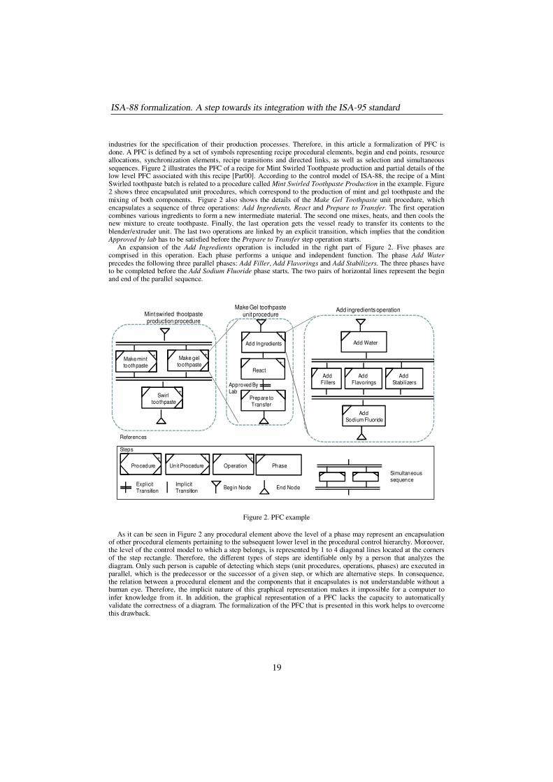
industries for the specification of their production processes. Therefore, in this article a formalization of PFC is done. A PFC is defined by a set of symbols representing recipe procedural elements, begin and end points, resource allocations, synchronization elements, recipe transitions and directed links, as well as selection and simultaneous sequences. Figure 2 illustrates the PFC of a recipe for Mint Swirled Toothpaste production and partial details of the low level PFC associated with this recipe [Par00]. According to the control model of ISA-88, the recipe of a Mint Swirled toothpaste batch is related to a procedure called Mint Swirled Toothpaste Production in the example. Figure 2 shows three encapsulated unit procedures, which correspond to the production of mint and gel toothpaste and the mixing of both components. Figure 2 also shows the details of the Make Gel Toothpaste unit procedure, which encapsulates a sequence of three operations: Add Ingredients, React and Prepare to Transfer. The first operation combines various ingredients to form a new intermediate material. The second one mixes, heats, and then cools the new mixture to create toothpaste. Finally, the last operation gets the vessel ready to transfer its contents to the blender/extruder unit. The last two operations are linked by an explicit transition, which implies that the condition Approved by lab has to be satisfied before the Prepare to Transfer step operation starts.
An expansion of the Add Ingredients operation is included in the right part of Figure 2. Five phases are comprised in this operation. Each phase performs a unique and independent function. The phase Add Water precedes the following three parallel phases: Add Filler, Add Flavorings and Add Stabilizers. The three phases have to be completed before the Add Sodium Fluoride phase starts. The two pairs of horizontal lines represent the begin and end of the parallel sequence.
Figure 2. PFC example
As it can be seen in Figure 2 any procedural element above the level of a phase may represent an encapsulation of other procedural elements pertaining to the subsequent lower level in the procedural control hierarchy. Moreover, the level of the control model to which a step belongs, is represented by 1 to 4 diagonal lines located at the corners of the step rectangle. Therefore, the different types of steps are identifiable only by a person that analyzes the diagram. Only such person is capable of detecting which steps (unit procedures, operations, phases) are executed in parallel, which is the predecessor or the successor of a given step, or which are alternative steps. In consequence, the relation between a procedural element and the components that it encapsulates is not understandable without a human eye. Therefore, the implicit nature of this graphical representation makes it impossible for a computer to infer knowledge from it. In addition, the graphical representation of a PFC lacks the capacity to automatically validate the correctness of a diagram. The formalization of the PFC that is presented in this work helps to overcome this drawback.
Make minttoothpaste
+Make gel
toothpaste
+
Swirl toothpaste
+
Mint swirled thootpasteproduction procedure
Add Ingredients
+
React
+
Prepare toTransfer
+
Make Gel toothpaste unit procedure
Add ingredients operation
Add Water
Add Fillers
Add Flavorings
Add Stabilizers
Add Sodium Fluoride
Procedure
+
Unit Procedure
+
Operation
+
Phase
Steps
Begin Node End NodeImplicit Transition
Explicit Transition
Simultaneous sequence
References
Approved By Lab
ISA-88 formalization. A step towards its integration with the ISA-95 standard
19
3 ISA-88 Formalization. A First Step towards its Integration with ISA-95
In order to deal with the semantic challenges introduced in section 1, this work proposes a formalization of the ISA-88 and ISA-95 standards by defining an ontology per each standard and then an ontology to integrate them. This approach avoids defining just one big ontology, which would be very complex and rigid, by sticking to a "divide and conquer" strategy.
The development of each ontology has been carried out separately. The formalization of ISA-88 has been done first because it is the one that has the major semantic inconsistencies in its term definitions. The models proposed within ISA-88 are taken into account to divide the proposed ontology into small ontology modules. The same approach was considered in the formalization of the other standard. Due to space limitations, only a part of the formalization of the ISA-88 ontology is presented in this paper. In particular, the main concepts involved in its Procedural Control Module, which is the one of the most advanced modules in this project's implementation, are introduced in the following paragraphs.
For the development of the Procedure Control ontology, an ad-hoc methodology based on well accepted principles has been proposed. It has the following four stages:
• Requirements specification: identifies the scope and purpose of the ontology. • Conceptualization stage: organizes and converts an informally perceived view of the domain into a semi-
formal specification using UML diagrams. • Implementation stage: codifies the ontology using a formal language. • Evaluation stage: allows making a technical judgment of the ontology quality and usefulness with respect
to the requirements specification, competency questions and/or the real world. It should be mentioned that these stages were not truly sequential; indeed, any ontology development is an
iterative and incremental process. If some need/weakness was detected during the execution of a given stage, it was possible to return to any of the previous ones to make modifications and/or refinements. Moreover, as it is proposed by Ontology Summit 2013 Communiqué [Neu13], some evaluation activities have been done in all the stages of the proposed development process. Some highlights of these methodological stages are given in the remaining of this section.
3.1 Requirement Specification
Competency questions, which were proposed by Uschold and Gruninger [Usc96] in their methodology, helped at this stage to identify the requirements. The gathered competency questions were classified in groups related to the levels defined in the control model. A small sample of the competency questions that were stated, are the following:
• Which are the procedural elements associated with a given Master Recipe? • Which are the conditions that should be fulfilled to start a given Operation? • Which are the operations comprised in a given Unit Procedure? • Which are the phases that need the conclusion of a given phase P in order to start their execution? • Which phases are executed in parallel with a given phase P?
3.2 Conceptualization
The second main step in the development process required the identification and capture of the domain concepts
and their relationships, trying to fulfill the previous requirements. To support this activity, UML (Unified Modelling
Language) [OMG13] was adopted. In addition to class diagrams, constraints about the objects in the model and
invariants on classes have been added using OCL (Object Constraint Language) [OMG14]. The complete results of
this stage are not described due to lack of space. However, a partial model will be described in this section.
As it was mentioned in Section 1.1, the ISA-88 procedural control model describes recipe procedures. Therefore,
the main concepts in the corresponding ontology are related to recipes and their components. Figure 3 introduces
the main concepts associated with recipe definition.
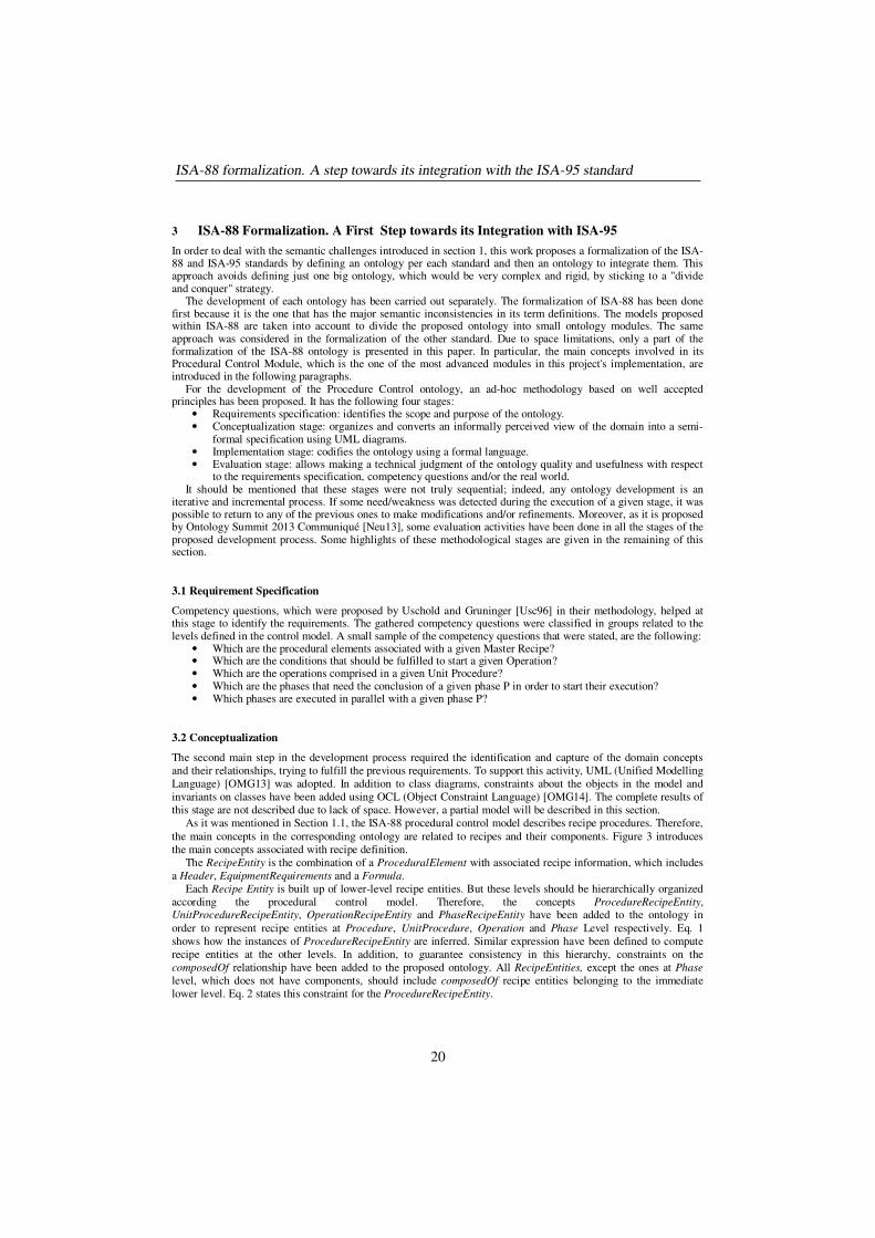
The RecipeEntity is the combination of a ProceduralElement with associated recipe information, which includes
a Header, EquipmentRequirements and a Formula.
Each Recipe Entity is built up of lower-level recipe entities. But these levels should be hierarchically organized
according the procedural control model. Therefore, the concepts ProcedureRecipeEntity, UnitProcedureRecipeEntity, OperationRecipeEntity and PhaseRecipeEntity have been added to the ontology in
order to represent recipe entities at Procedure, UnitProcedure, Operation and Phase Level respectively. Eq. 1
shows how the instances of ProcedureRecipeEntity are inferred. Similar expression have been defined to compute
recipe entities at the other levels. In addition, to guarantee consistency in this hierarchy, constraints on the
composedOf relationship have been added to the proposed ontology. All RecipeEntities, except the ones at Phase
level, which does not have components, should include composedOf recipe entities belonging to the immediate
lower level. Eq. 2 states this constraint for the ProcedureRecipeEntity.
ISA-88 formalization. A step towards its integration with the ISA-95 standard
20
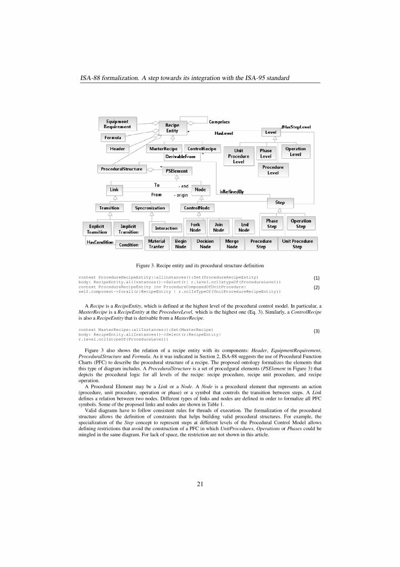
Figure 3. Recipe entity and its procedural structure definition
context ProcedureRecipeEntity::allInstances():Set(ProcedureRecipeEntity)
body: RecipeEntity.allInstances()->Select(r| r.level.oclIstypeOf(ProcedureLevel)) (1)
context ProcedureRecipeEntity inv ProcedureComposedOfUnitProcedure:
self.component->forall(r:RecipeEntity | r.oclIsTypeOf(UnitProcedureRecipeEntity)) (2)
A Recipe is a RecipeEntity, which is defined at the highest level of the procedural control model. In particular, a
MasterRecipe is a RecipeEntity at the ProcedureLevel, which is the highest one (Eq. 3). Similarly, a ControlRecipe
is also a RecipeEntity that is derivable from a MasterRecipe.
context MasterRecipe::allInstances():Set(MasterRecipe)
body: RecipeEntity.allInstances()->Select(r:RecipeEntity|
r.level.oclIstypeOf(ProcedureLevel))
(3)
Figure 3 also shows the relation of a recipe entity with its components: Header, EquipmentRequirement,
ProceduralStructure and Formula. As it was indicated in Section 2, ISA-88 suggests the use of Procedural Function
Charts (PFC) to describe the procedural structure of a recipe. The proposed ontology formalizes the elements that
this type of diagram includes. A ProceduralStructure is a set of procedgural elements (PSElement in Figure 3) that
depicts the procedural logic for all levels of the recipe: recipe procedure, recipe unit procedure, and recipe
operation.
A Procedural Element may be a Link or a Node. A Node is a procedural element that represents an action
(procedure, unit procedure, operation or phase) or a symbol that controls the transition between steps. A Link
defines a relation between two nodes. Different types of links and nodes are defined in order to formalize all PFC symbols. Some of the proposed links and nodes are shown in Table 1.
Valid diagrams have to follow consistent rules for threads of execution. The formalization of the procedural
structure allows the definition of constraints that helps building valid procedural structures. For example, the
specialization of the Step concept to represent steps at different levels of the Procedural Control Model allows
defining restrictions that avoid the construction of a PFC in which UnitProcedures, Operations or Phases could be
mingled in the same diagram. For lack of space, the restriction are not shown in this article.
ISA-88 formalization. A step towards its integration with the ISA-95 standard
21
Table 1: Different types of links and nodes
Type of Link
Transition A direct link between nodes.
Implicit Transition A transition whose only condition is that the directly preceding step has to finish its execution.
Explicit Transition A transition having a condition that has to evaluate to true in order to
activate the following step in the transition.
Synchronization A link that relates recipe elements among which there is a certain form of
synchronization.
Material
Transfer
A link that represents material transfer from a step to another one.
Interaction A kind of synchronization that does not involve movement of material.
Type of Node
Step A node that represents a recipe procedural element: procedure recipe entity, unit
procedure recipe entity, operation recipe entity or phase recipe entity. According to the level of the procedure control model associated to the PFC in which the step is
defined, this concept can be specialized in ProcedureStep, UnitProcedureStep,
OperationStep, and PhaseStep.
Control Node A node that controls de intended thread of execution of the recipe procedural
elements.
Begin Node A node that identifies the start of each procedural structure and/or each subordinate
structure.
End Node A node that indicates the end of a procedural structure and/or a subordinate structure.
Fork Node A node that defines the start of independent threads of execution of certain recipe
elements, which are executed in parallel.
Join Node A node that indicates the end of independent threads of execution.
Decision Node A node that specifies the beginning of alternative threads of execution.
Merge Node A node that shows the joining of alternative threads of execution.
3.3 Implementation and Evaluation
The main goal of the ontology implementation activity is to create a computable model deployed in an ontology language from the conceptual model created during the conceptualization phase. Based on its ample acceptance, the OWL 2 language [14], developed by the W3C (World Wide Web Consortium), was chosen to implement the ontology and the Protegé 4.3 editor has been selected to support the ontology development and implementation.
The development process has been guided by the principles of coherence, conciseness, intelligibility, adaptability, minimal ontological commitment and efficiency. Some of these principles are conflicting among themselves. Due to such incompatibilities, a suitable balance between the clashing principles was sought. Nowadays it is widely accepted that there is a lack of a formal methodology that considers all these criteria, which could be applied to evaluate domain ontologies. According to Gómez-Pérez [Gom96] , the ontology evaluation phase comprises three aspects: (i) ontology validation, (ii) ontology verification, and (iii) ontology assessment. Validation and verification activities are associated with a technical judgment of the content of the ontology with respect to a frame of reference, which can be requirement specifications, competency questions, or the real world. In turn, assessment focuses on judging the ontology content from the user’s point of view. The results of using the proposed ontology in the development of different types of applications in various contexts are required to be analyzed in order to assess the ontology.
Although there is no formal methodology that considers all the aforementioned evaluation criteria, many authors have reached an agreement on assessment needs during all the ontology lifecycle stages [Neu13]. Having them in mind, partial evaluation through competency questions has been done during the implementation phase. To do so,
ISA-88 formalization. A step towards its integration with the ISA-95 standard
22
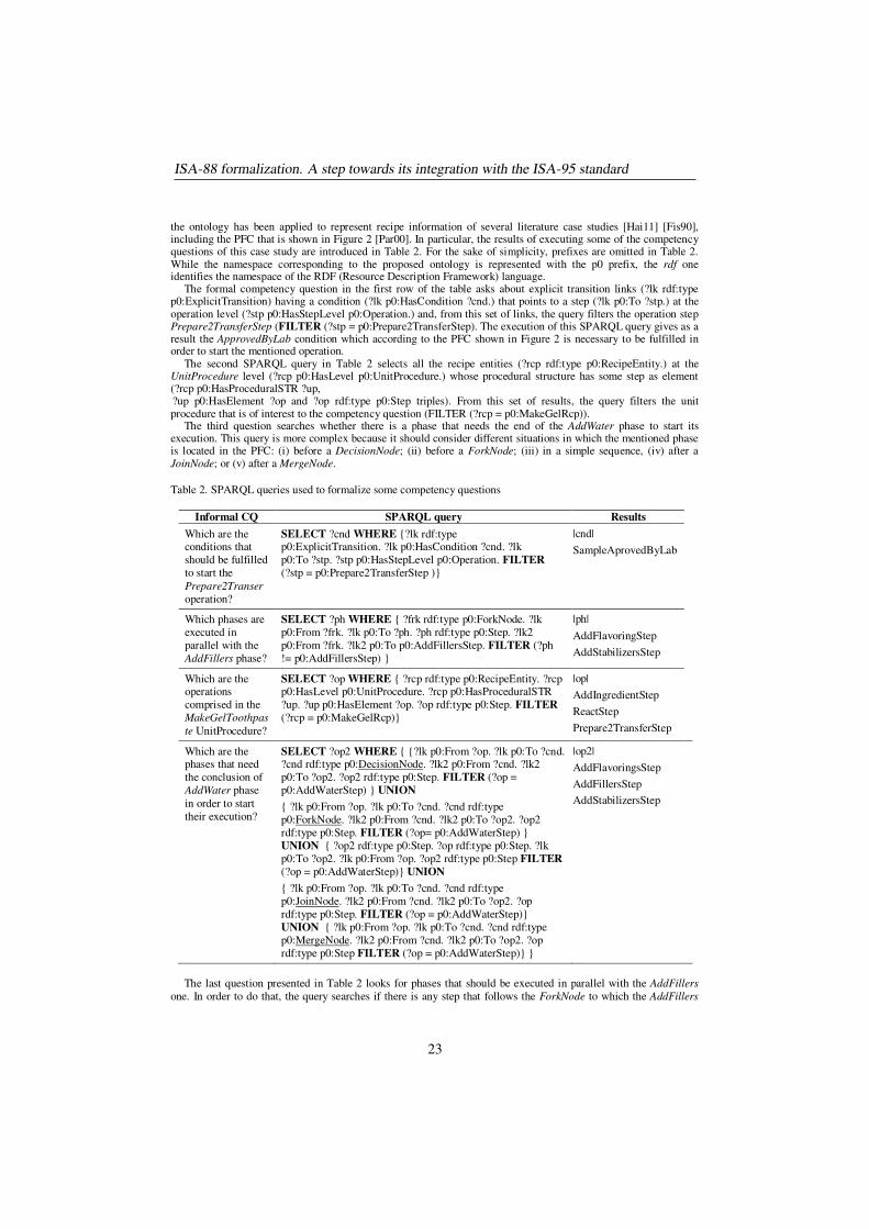
the ontology has been applied to represent recipe information of several literature case studies [Hai11] [Fis90], including the PFC that is shown in Figure 2 [Par00]. In particular, the results of executing some of the competency questions of this case study are introduced in Table 2. For the sake of simplicity, prefixes are omitted in Table 2. While the namespace corresponding to the proposed ontology is represented with the p0 prefix, the rdf one identifies the namespace of the RDF (Resource Description Framework) language.
The formal competency question in the first row of the table asks about explicit transition links (?lk rdf:type p0:ExplicitTransition) having a condition (?lk p0:HasCondition ?cnd.) that points to a step (?lk p0:To ?stp.) at the operation level (?stp p0:HasStepLevel p0:Operation.) and, from this set of links, the query filters the operation step Prepare2TransferStep (FILTER (?stp = p0:Prepare2TransferStep). The execution of this SPARQL query gives as a result the ApprovedByLab condition which according to the PFC shown in Figure 2 is necessary to be fulfilled in order to start the mentioned operation.
The second SPARQL query in Table 2 selects all the recipe entities (?rcp rdf:type p0:RecipeEntity.) at the UnitProcedure level (?rcp p0:HasLevel p0:UnitProcedure.) whose procedural structure has some step as element (?rcp p0:HasProceduralSTR ?up, ?up p0:HasElement ?op and ?op rdf:type p0:Step triples). From this set of results, the query filters the unit procedure that is of interest to the competency question (FILTER (?rcp = p0:MakeGelRcp)).
The third question searches whether there is a phase that needs the end of the AddWater phase to start its execution. This query is more complex because it should consider different situations in which the mentioned phase is located in the PFC: (i) before a DecisionNode; (ii) before a ForkNode; (iii) in a simple sequence, (iv) after a JoinNode; or (v) after a MergeNode.
Table 2. SPARQL queries used to formalize some competency questions
Informal CQ SPARQL query Results
Which are the conditions that
should be fulfilled
to start the
Prepare2Transer
operation?
SELECT ?cnd WHERE {?lk rdf:type p0:ExplicitTransition. ?lk p0:HasCondition ?cnd. ?lk
p0:To ?stp. ?stp p0:HasStepLevel p0:Operation. FILTER
(?stp = p0:Prepare2TransferStep )}
|cnd|
SampleAprovedByLab
Which phases are
executed in
parallel with the
AddFillers phase?
SELECT ?ph WHERE { ?frk rdf:type p0:ForkNode. ?lk
p0:From ?frk. ?lk p0:To ?ph. ?ph rdf:type p0:Step. ?lk2
p0:From ?frk. ?lk2 p0:To p0:AddFillersStep. FILTER (?ph
!= p0:AddFillersStep) }
|ph|
AddFlavoringStep
AddStabilizersStep
Which are the operations
comprised in the
MakeGelToothpas
te UnitProcedure?
SELECT ?op WHERE { ?rcp rdf:type p0:RecipeEntity. ?rcp p0:HasLevel p0:UnitProcedure. ?rcp p0:HasProceduralSTR
?up. ?up p0:HasElement ?op. ?op rdf:type p0:Step. FILTER
(?rcp = p0:MakeGelRcp)}
|op|
AddIngredientStep
ReactStep
Prepare2TransferStep
Which are the phases that need
the conclusion of
AddWater phase
in order to start
their execution?
SELECT ?op2 WHERE { {?lk p0:From ?op. ?lk p0:To ?cnd. ?cnd rdf:type p0:DecisionNode. ?lk2 p0:From ?cnd. ?lk2
p0:To ?op2. ?op2 rdf:type p0:Step. FILTER (?op =
p0:AddWaterStep) } UNION
{ ?lk p0:From ?op. ?lk p0:To ?cnd. ?cnd rdf:type
p0:ForkNode. ?lk2 p0:From ?cnd. ?lk2 p0:To ?op2. ?op2
rdf:type p0:Step. FILTER (?op= p0:AddWaterStep) }
UNION { ?op2 rdf:type p0:Step. ?op rdf:type p0:Step. ?lk
p0:To ?op2. ?lk p0:From ?op. ?op2 rdf:type p0:Step FILTER
(?op = p0:AddWaterStep)} UNION
{ ?lk p0:From ?op. ?lk p0:To ?cnd. ?cnd rdf:type
p0:JoinNode. ?lk2 p0:From ?cnd. ?lk2 p0:To ?op2. ?op
rdf:type p0:Step. FILTER (?op = p0:AddWaterStep)}
UNION { ?lk p0:From ?op. ?lk p0:To ?cnd. ?cnd rdf:type
p0:MergeNode. ?lk2 p0:From ?cnd. ?lk2 p0:To ?op2. ?op
rdf:type p0:Step FILTER (?op = p0:AddWaterStep)} }
|op2|
AddFlavoringsStep
AddFillersStep
AddStabilizersStep
The last question presented in Table 2 looks for phases that should be executed in parallel with the AddFillers
one. In order to do that, the query searches if there is any step that follows the ForkNode to which the AddFillers
ISA-88 formalization. A step towards its integration with the ISA-95 standard
23
phase is linked to. If the mentioned phase does not follow a ForkNode, the query gives an empty result because
AddFillers is not in a parallel sequence.
The implementation of several cases studies, as well as the formalization and execution of the whole set of
competency questions have allowed the identification of missing concepts and properties that have to be added to
the ontology. Among others, these concepts are related to the detailed description of equipment units and their
relations to recipes and the different levels of the procedural control model.
4 Conclusions and Future Work
This contribution describes an ontology based approach that can play a central role in solving nowadays integration
problems that appear in the enterprise hierarchical planning pyramid when adopting the ISA-88 and ISA-99
standards. The definition of three ontologies is suggested: one per each standard formalization and another ontology
to integrate the previous ones. In particular, the article focuses on the formalization of PFCs, the graphical
representation of the recipe procedures proposed by ISA-88. Since knowledge is explicitly and formally expressed, the ontology supports inference processes and an analysis of the construction of valid PFCs. In addition, some
methodological aspects of the proposed ontology development process are also shown.
It is necessary to perform more activities to evaluate and validate the proposed formalization. In parallel with
these tasks, the formalization of ISA-95 and the definition of the integration ontology are being carried out.
Acknowledgements.
The authors acknowledge the financial support received from CONICET (PIP 11220110100906 and PIP 11220110101145), UNL (PI CAI+D 2011) and UTN (PID 25-O156).
References
[Ans00] ANSI/ISA-95.00.01-2000: Enterprise-Control System Integration. Part 1: Models and terminology,
2000.
[Ans10] ANSI/ISA–88.00.01: Batch Control Part 1: Models and Terminology, 2010.
[Fis90] Fisher, T. Batch Control Systems: Design, Application and Implementation. Instrument Society of
America, North Carolina, 1990.
[Gom96] Gómez-Pérez, A.: A Framework to Verify Knowledge Sharing. Experts Systems with Application 11,
519–529, 1996.
[Hai11] Hai, R., M. Theiβen, W. Marquardt: An Ontology Based Approach for Operational Process Modeling. Advanced Engineering Informatics, 25, 748-759, 2011.
[Har09] Harjunkoski, I., Nyström, R., Horch, A.: Integration of Scheduling and Control – Theory or Practice?
Computers and Chemical Engineering, 33, 1909-1918, 2009.
[ISO04] ISO 18629 - Process specification language. Part 1: Overview and basic principles, 2004.
[Kre06] Kreipl, S., Dickersback, J.T., Pinedo, M.: Coordination Issues in Supply Chain Planning and
Scheduling. In: Herrmann, J. (ed), Handbook of Production Scheduling, 177-212. Springer ,2006.
[Mar09] Maravelias, C., Sung C., Integration of Production Planning and Scheduling: Overview, challenges
and opportunities, Computers and Chemical Engineering, 33, 1919-1930, 2009.
[Mun10] Muñoz, E., Espuña, A., Puigjaner, L.: Towards an Ontological Infrastructure for Chemical Batch
Process Management, Computers and Chemical Engineering, 34, 668-682, 2010.
[Neu13] Neuhaus, F., Vizedom, A., Baclawski, K., Bennett, M., Dean, M., Denny, M., Grüninger,
M., Hashemi, A., Longstreth, T., Obrst, L., Ray, S., Sriram, R., Schneider, T., Vegetti, M., West,
M., Yim, P. Towards Ontology Evaluation Across the Life Cycle. Journal of Applied Ontology, 8,
179-194, 2013.
[OMG13] Object Management Group. Unified Modeling Language (UML) Version 2.5 - Beta 2
http://www.omg.org/spec/UML/2.5/Beta2/. 2013
[OMG14] Object Management Group. Object Constraint Language (OCL) Version 2.4.
http://www.omg.org/spec/OCL/. 2014
[Par00] Parshall, J., L. Lamb. Applying S-88: Batch Control from a User’s Perspective. Instrument Society of
America, North Carolina, 2000.
ISA-88 formalization. A step towards its integration with the ISA-95 standard
24

[Sho02] Shobrys, D.E, White, D.C.: Planning, Scheduling and Control Systems: Why Cannot they Work
Together? Computers and Chemical Engineering 26, 149-160, 2002.
[Usc96] Uschold, M. and M. Gruninger. Ontologies: Principles, Methods and Applications. Knowledge
Engineering Review 11, 93-155, 1996.
[W3c04] W3C OWL Working Group, OWL 2 Web Ontology Language Document Overview. Technical Report. http://www.w3.org/TR/owl2-overview/. 2004
ISA-88 formalization. A step towards its integration with the ISA-95 standard
25

Improving Ontology Service-DrivenEntity Disambiguation
A. Patrice SEYED a Zachary FRY b and Deborah L. MCGUINNESS b
a 3M HIS, Silver Spring, MDb Rensselaer Polytechnic Institute, Department of Computer Science,
Tetherless World Constellation, Troy, NY
Abstract.One of the long-standing challenges in natural language processing is uniquely
identifying entities in text, which when performed accurately and with formal on-tologies, supports efforts such as semantic search and question-answering. Withthe recent proliferation of comprehensive, formalized sources of knowledge (e.g.,DBpedia, Freebase, OBO Foundry ontologies) and advancements in supportive Se-mantic Web technologies and services, leveraging such resources to address the en-tity disambiguation problem in the industry setting as “off the shelf” within natu-ral language processing pipelines becomes a more viable proposition. In this pa-per, we evaluate this viability by building and evaluating an entity disambiguationpipeline founded on publicly available ontology services, namely those providedby the NCBO BioPortal. We chose BioPortal due to its current use as an ontologyrepository and provider of ontological services for the biomedical informatics com-munity. To consider its usage outside the biomedical domain, and given our imme-diate project goal for facilitating semantic search over Earth science datasets for theDataONE project, we focus on the disambiguation of geographic entities. For thiswork, we leverage NCBO’s Term service in conjunction with NCBO’s entity dis-ambiguation service, the Annotator, to demonstrate an enhancement of the Annota-tor service, through application of a vector space model representation of ontolog-ical entities and relationships to drive scoring improvements. This work ultimatelyprovides a methodology and pipeline for improving publicly available ontologyservice-based entity disambiguation, demonstrated through an enhanced version ofthe NCBO Annotator service for geographic named entity disambiguation.
Keywords. entity disambiguation, ontology, geospatial
Introduction
One of the long-standing challenges in natural language processing is uniquely identify-ing entities in text, which when performed accurately and with formal ontologies, sup-ports efforts such as semantic search and question-answering. Semantic search wouldgreatly facilitate our project, the Data Observation Network for Earth (DataONE), as itis aimed at limiting the excessive time and effort spent to discover, acquire, interpret,and use related data for biological, ecological, environmental and Earth science data.1
1 http://dataone.org
26
The DataONE metadata catalog is composed of content uploaded by participating re-search institutions, that includes a keywords field populated by data managers, wherethese keywords and keyword-“worthy” terms in the scientific abstracts are not yet linkedto domain knowledge in a formal way to aid discovery, besides what exist as disparatecontrolled vocabularies. Clearly here, the use of publicly available formal ontologies todisambiguate terms of relevance for search provides advanced capabilities for precisesearch and a “free extension” to their existing vocabularies that does not require manualdevelopment.
With the recent proliferation of comprehensive, formalized sources of knowledge(e.g., DBpedia,2 Freebase,3 OBO Foundry ontologies4) and advancements in supportiveSemantic Web technologies and services, leveraging these resources to address the entitydisambiguation problem in the industry setting as “off the shelf” within natural languageprocessing pipelines becomes a more viable proposition. In this paper, we evaluate thisviability by building and evaluating a novel entity disambiguation pipeline founded onpublicly available ontology services, namely those provided by the NCBO BioPortal. Wechose BioPortal due to its central role as a ontology repository and provider of ontolog-ical services for a given community, that being biomedical informatics. To consider itsusage outside the biomedical domain, and given our immediate project goal for facilitat-ing semantic search over Earth science datasets for the DataONE project, we focus onthe disambiguation of geographic entities, using the Gazetteer Ontology (GAZ).
In this work, we use NCBO’s Term service in unison with NCBO’s own entity dis-ambiguation service, the NCBO Annotator, to demonstrate an enhancement over the An-notator service, using a vector space representation of ontological entities and relation-ships to drive scoring improvements. Fittingly then, we evaluate our results against theNCBO Annotator, and apply the TopN scoring method, since both systems are suitedto provide inputs to a semi-automated semantic-mapping workbench environment. Ul-timately, this work evaluates whether our techniques improve on TopN mapping accu-racy of the Annotator service, including if introducing all domain-level relationships intothe vector space provides additional discriminatory power over just those relationshipsconsidered “broader”, while at the same time provides insights into the process of us-ing and augmenting publicly available ontology-service driven web services for entitydisambiguation.
Our overall approach extracts named entity labels from natural language text, andwhere applicable, maps each to a resource of an ontology that best represents and disam-biguates its meaning. The set of entities that can be disambiguated within our pipelineis flexible, to disambiguate what in the formal ontology community is referred to as par-ticulars or concepts (or types), and what in the Web Ontology Language (OWL) con-siders individuals or classes,5 that the Semantic Web community at large via the Re-source Description Framework (RDF) refers to simply as resources.6 Thus we describeour pipeline at the abstraction of “resource”, and where appropriate for its current ap-plication we describe how it functions for geographic named entities disambiguation. Inthe following sections we describe related work, background on the topic-based vector
2 http://dbpedia.org/3 http://www.freebase.com/4 http://www.obofoundry.org/5 http://www.w3.org/TR/owl-ref/6 http://www.w3.org/TR/1999/REC-rdf-syntax-19990222/
Improving Ontology Service-Driven Entity Disambiguation
27
space model algorithm we apply, and our methodology and pipeline that utilizes thesealgorithms and services. In Section 4 we evaluate results using the TopN scoring met-ric, comparing against the existing annotation service using an initial, hand-curated goldstandard. In Section 5 we present qualitative findings that resulted from application ofour the pipeline, and in sections 6 and 7 we discuss future work and conclusions.
1. Background on eTVSM
In this section we formally present the definition and implementation of an eTVSMmodel [10][5]. An eTVSM formalizes how resources represent named entity labels byfirst including a TVSM of the ontology, and then representing entity labels within theTVSM based on links between named entity labels and resources. The first step in build-ing an eTVSM is to encode a graph representation of resources connected through agiven set of relationships into resource vectors that compose a TVSM. This graph repre-sentation is based on candidate resources and their related resources. (We consider can-didate resources those resources which are discovered by initial lexical matching andpotentially represent to what a named entity label refers.) For each resource, we considerP(r,k) to be the power set of all resources at distance k from resource r. We construct aresource vector~r as follows:
~t =
⟨β
∑k=0
∑r1∈P(r,k)
αk, . . . ,β
∑k=0
∑rn∈P(r,k)
αk
⟩,~r =
1‖~t‖
~t (1)
Each resource in the graph representation of an ontology is assigned an index from 1to n, which means that each resource vector has size n and there are n resource vectors.The vector for resource n is calculated by assigning an exponentially declining weightto connected resources and summing the total weights for each resource. For example,resource i is assigned a weight of 1, all resources one node away from i adds a weight of0.5, resources two nodes away from i add a weight of 0.25, etc. The sum of the weightsare normalized. In this way we assign a resource vector to each candidate resource. Theconstant α is an exponential decay which is used to determine how important resourcesare distant from the candidate. [5] experiments with different decay values and identify .9as being optimal for the DBpedia Ontology; in our work we apply an exponential decayconstant of .5 and leave this analysis for future work. The constant β is used to limit thedistance between resources that we wish to consider; in our case β is 5.
Next, an interpretation vector is constructed from an interpretation, i, which is aunique mapping of a named entity label to a resource, which we multiply by an ambiguityweight:
~i =~r g(i) (2)
In order to reduce the effects of ambiguous mappings (i.e., which map labels to multipleresources), we weigh each interpretation vector by an ambiguity weight g(i), defined as:
g(i) =1
| j : j ∈ I(k),k ∈ K(i)| (3)
Improving Ontology Service-Driven Entity Disambiguation
28
The ambiguity weight g(i) forces labels which are mapped to many resources to haveless weight toward disambiguating other named entity labels. Here, K(i) is the set of alllabels for interpretation i, and I(K) is the set of all interpretations derived from label k.We represent the document as the collection of all resource mappings by summing theweighted interpretation vectors:
~td = ∑i∈I
wd,i~i (4)
Each interpretation vector is weighted by multiplying the frequency at which the namedentity label for interpretation i is found in the extracted named entities from documentd. The cosine similarity metric is used to compare individual interpretation vectors forthe document against the document vector,~td . Incorrect interpretations will not signif-icantly affect the document vector and result in a low cosine similarity score, whereasinterpretations that are more similar to other interpretations will result in a higher cosinesimilarity.
2. Pipeline
We apply a three-phase pipeline for executing our entity disambiguation approach, in-cluding NER, resource mapping, and eTVSM scoring. We describe each phase as ablack-box system, with inputs and outputs which link the phases together. Our overallpipeline takes as input an unstructured text document in the form of a science publicationabstract from DataONE outputs a ranked list of candidate resources.
The NER phase of our pipeline extracts named entities embedded in unstructuredtext using the Natural Language Tool Kit (NLTK) [11]. This phase serves the sole pur-pose of generating a set of labels to be processed for resource mapping in the next phase.The NLTK software library contains NER algorithms that extract named entity labelsfrom unstructured text. It applies a series of tokenizers to parse sentences into terms,and using part-of-speech tagging generates parse trees as input to supervised learningalgorithms for named entity detection. The unstructured text which is passed through theNER phase of our pipeline outputs a list of named entity labels for each given document.
The resource-mapping phase of our pipeline processes a list of named entity labelsand returns a set of named entity label to resource mappings and an ontology portion(i.e., a set of statements) describing each matched resource. In the context of geospatialnamed entity recognition, there are multiple resources which are referred to by the samepreferred label annotation. For example, in the United States, the city of Springfieldcan refer to greater than 40 different cities located in multiple states. Also some states,such as Wisconsin, have multiple cities named Springfield. Therefore, the purpose ofthe resource-mapping phase is to map each named entity label to those resources whichdefine a unique instance of that particular location with that name. For every namedentity label extracted from the NER phase, we query the NCBO Annotator Service for alist of candidates, that is, resources which could potentially define that particular namedentity within an ontology.
Next, we obtain statements about the resources, including annotations as well asobject property and subclass statements, using the NCBO Term Service, by supplying a
Improving Ontology Service-Driven Entity Disambiguation
29
resource URI and ontology identifier as parameters to the service.7 The object propertyand subclass-based statements are filtered according to a preselected set of properties,where the objects of these statement are recursively submitted to the Term Service. In thisway, we perform a breadth-first search along a set of properties until the final resourcein the path is reached. This phase concludes when the statements are collected for eachcandidate resource.
The eTVSM scoring phase scores each entity label-to-resource mapping in a givendocument by first generating a TVSM of the obtained ontology graph, and then encodingthe resource mappings into an eTVSM. We use the cosine similarity metric to determinehow strongly one candidate resource is related to all candidate resources for a given doc-ument [5]. Given an eTVSM that encodes each mapping of a named entity label to can-didate resources into a vector space, closely related candidate resources will have higherscores than those than are more indirectly related or not related at all to other candidateresources. Ultimately, the eTVSM scoring phase provides a quantitative measure for howstrongly a resource disambiguates a named entity label.
3. Evaluation
In this section we introduce a small hand-annotated dataset which we use as a goldstandard for comparing our result against the existing NCBO Annotator Service. Wescore output from the NCBO Annotator Service and from our pipeline using the TopNscoring metric. We demonstrate how our approach contributes an enhancement to theNCBO Annotator Service for geographic named entity disambiguation using the eTVSMalgorithm. The process for which we created our gold standard is described below.
First, we selected scientific paper abstracts by processing each abstract through ourpipeline and selecting those which have at least one named entity label that has greaterthan 10 candidate concept mappings. This decision was due to a lack of preexisting goldstandard data and our desire to disambiguate highly ambiguous named entity labels. Foreach named entity label we hand-annotated it with a concept in the Gazetteer Ontologywhich correctly identifies it. The result is 24 unique named entities labels, which wereextracted using the NER phase of our pipeline. For these 24 named entity labels, thereare 18 unique candidate concepts contained in the GAZ ontology, which we discoveredby querying the annotator service with our named entity labels. The remaining six namedentity labels were either too generic for us to assign a unique concept, or the correct con-cepts are not contained in the most current version of GAZ; in order to get a meaningfulcomparison of our pipeline against the NCBO Annotator Service we excluded these sixlabels for our evaluation. The 18 named entity labels were hand-mapped to concepts inGAZ, composing our gold standard dataset which we use in our evaluation.
In the setting of a semantic-mapping workbench, when a prospective curator inspectsthe list of candidate concepts for a set of named entities extracted from a document, themost accurate or correct concept will ideally appear at or near the top of a ranked listof candidate concepts. In fact, the Annotator website presents candidate concepts in thisranked manner. To be fair, there are just two levels of ranking produced by the Annotator
7 We describe the atoms of the ontology portion extraction in terms of statements, to maintain our abstrac-tion at the level of resources. In the case of named entity disambiguation these statements are a mix ofassertions and axioms, and in the case of conceptual entities these statements are primarily axioms.
Improving Ontology Service-Driven Entity Disambiguation
30
service, determined by whether a match was made on the preferred or alternate term,while our approach uses a much more granular similarity score metric. Still, we evaluateour augmented version of the annotator alongside the publicly available Annotator Ser-vice in order to demonstrate improvement upon the existing service. Therefore we evalu-ate the two approaches using the position of the correct concept returned in a ranked listof concept-mapping scores. To do this, we use the TopN scoring metric [12,5]:
TopN =
N∑j=1
αk jc
N∑
i=1α i
c
(5)
where N is the number of named entity labels which are mapped to a concept in thegold standard. k j is the position of concept j in the returned concepts from the AnnotatorService. αc is an exponential decay coefficient used for penalizing concepts that appearlater in the list. A score of 1 is realized for a document if for all named entity labels,the top scoring candidate concept corresponds to the gold standard’s concept for thatdocument. Note that since we only consider concepts that are in our gold standard, andby definition, are returned by the Annotator Service, the TopN score can never have avalue of 0. However, if all the correct concepts for each entity are returned at the bottomof the list, the TopN score will be significantly small. We chose a value of 0.8 for ourconstant αc, so, for example, the position of the correct concept will contribute 0.1 to thescore if it appears in the tenth position [5].
For the evaluation of our pipeline, we construct our vector space using two methods.The first construction uses located in, while the second uses all (13) relationships con-tained in the GAZ ontology. This comparison provides some evidence that including rela-tionships beyond those considered generalizations improves scoring. Table 189 shows thecomparison between the NCBO Annotator Service and our pipeline as constructed usingthe two methods. These results demonstrate that the application of the eTVSM-scoringphase outperforms the Annotator Service for disambiguating geographic named entities.The results demonstrate that a quantitative approach for disambiguation which measuresand ranks the strength of each concept mapping outperforms an approach which relieson simple lexical matching.
4. Qualitative Findings
In this section we present some qualitative insights of applying our pipeline to a samplescientific publication abstract. Figure 110 shows a graph output of our pipeline as appliedto a sample scientific abstract. In this run we included all geographic relationships fromGAZ during the concept-mapping phase.
We confirmed that our ontology-based resource mapping approach successfullydown ranks irrelevant resources and thus outperforms purely lexical-based resource map-
8 A version of this paper with figures included is available athttp://tw.rpi.edu/web/doc/ImprovingOntologyServiceDrivenEntityDisambiguation/.
9 https://www.flickr.com/photos/127739444@N02/15066654769/10 https://www.flickr.com/photos/127739444@N02/15230553716/
Improving Ontology Service-Driven Entity Disambiguation
31
pings. For instance, where only lexical matching algorithms are used (e..g., the cur-rent Annotator Service), the entity label ‘Oregon’ receives equal ranking for “Stateof Oregon (GAZ:00002515)” as resources “Oregon (GAZ:22225751)” and “Oregon(GAZ:00084619)” (cities in Michigan and Illinois). Our approach leverages fine-grainedgeographic relationships and considers relationships with other mapped named entitiesmentioned in the same abstract (e.g., Deer Creek, Josephine County), so that the similar-ity score of the mismatches for ‘Oregon’ is significantly lower than the correct one.
We also identified improvements to the scoring of correct resources after applyingadditional relationships in the resource-mapping phase of our pipeline, beyond thoseconsidered generalizations (e.g., located in). For example, for the abstract of the fourthstudy of our gold standard, the named entity label ‘Cumberland River’ was mapped tothree distinct candidates. When only the located in relationship is applied, the two incor-rect resources received a score while the correct resource (GAZ:00150754) did not (seeleft side of Table 211); however, when applying all geographic relationships, the correctresource accurately received the highest score. This is due to relationships to other re-sources, via the inclusion of additional kinds of geographic relationships, that have beenmapped to other named entity labels extracted from the abstract (shown in Figure 212).
Finally, we learned that our pipeline improves the quality of ontologies availablethrough Bioportal, by facilitating curators in the process of identifying and reporting ex-isting gaps. For example, in an abstract that mentions the Deer Creek Field Station andEducational Center of the state of Oregon, the named entity label ‘Deer Creek’ returned29 unique resources labeled as ‘Deer Creek’, none of which were the correct one. We in-formed the GAZ team, who quickly created the resource and appropriate statements, in-creasing coverage of the ontology. Figure 1 illustrates the results of the pipeline after thenewly added resource “Deer Creek (GAZ:00633440)” was included, which became thehighest ranking candidate resource for ‘Deer Creek’ due to relationships to “JosephineCounty” and “State of Oregon”.
5. Related Work
In this section we discuss recent work that applies ontologies to the named entity recog-nition (NER) problem, including that which the current work uses and builds upon:the NCBO Annotator and enhanced topic-based vector space modeling (eTVSM). Re-searchers at the BBC experimented with eTVSMs [10] to automatically apply editor tagsto archived radio programs for use in a manual curation environment [5]. Concepts con-tained in the DBpedia ontology were represented in a topic-based vector space model(TVSM), a model constructed by creating vectors for each concept that include thoseconcepts related by SKOS broader13. The eTVSM was built by linking text transcribedfrom radio programs to concepts in the DBpedia Ontology,14 scoring each link using therelationships between concepts that were encoded in the TVSM. Links that were closelyrelated scored higher, while incorrect links which were not as closely related scoredlower. Our work reuses the same underlying theory for using a vector space model for
11 https://www.flickr.com/photos/127739444@N02/15066727059/12 https://www.flickr.com/photos/127739444@N02/15253595325/13 http://www.w3.org/2004/02/skos/14 http://wiki.dbpedia.org/Ontology
Improving Ontology Service-Driven Entity Disambiguation
32
disambiguation, and additionally explores the benefits of using relationships more ex-plicit than broader, to take advantage of knowledge beyond that found in a generalizationhierarchy, formalized by expert curators.
The NCBO BioPortal project supports efforts to linking unstructured text to ontolo-gies through publicly accessible services for leveraging community based ontologies [2].The NCBO Annotator Service matches inputted text to ontological terms contained incommunity-developed ontologies by applying a lexical string matching algorithm to alexicon based on preferred and synonym labels [3,4].15 By default, the Annotator Ser-vice is configured to consider all ontologies published through BioPortal, however thereis a parameter for restricting it to a set of target ontologies. [3] highlights the additionalneed for enhancing the service by developing components that use the knowledge in on-tologies to recognize relationships between concepts, which is a focus of this paper. Theservice returns a list of candidate concepts from the selected ontologies and providesa score for each candidate concept based on whether the concept was matched on pre-ferred label or synonym. Our approach builds on this service and ultimately creates anenhanced version of it that quantitatively measures how suitable each candidate conceptrepresents a named entity. Further, our approach and pipeline starts by recognizing to-kens in the text, while the Annotator spots named entities using terms from the targetontologies and supporting lexicons. Therefore with our approach a curator is more easilyable to find and report gaps in the existing ontologies in a semantic-mapping workbenchsetting, since extracted token are immediately available for inspection. We describe howwe practically applied this mechanism in Section 3.
Aside from the BBC and NCBO efforts, there exists extensive previous researchin the area of entity disambiguation leveraging ontology or more generally, linked datasources. Alexopoulos et al. [6] propose a disambiguation framework that utilizes DB-Pedia to detect intended meaning of named entities (e.g., soccer clubs, organizations) inunstructured text, using an algorithm similar to [10]. Kleb et al. [8] focus on disambigua-tion using spreading activation on an RDFS-based ontologies. Mendes et al. [9] providesdisambiguation and mapping to DBpedia URIs, within DBpedia Spotlight. Hoffart [7]applies a novel collective disambiguation strategy using a new form of coherence graphusing DBpedia and Yago. There are also many off-the-shelf concept extraction toolsavailable: Open Calais,16 Zemanta,17 Alchemy API18); all of these approaches identifyentities and generate URIs for them through disambiguation.
Our work differs from these in that we focus on the practicality of using NCBOBioportal and its APIs as an ”off the shelf” resource for applying eTVSM for semanticdisambiguation within an NLP pipeline. BioPortal is of particular interest because theontologies registered with it include many that are developed by expert curators. Thebenefit of our approach is that the more explicit relationships and to what resources theyrelate are used for disambiguation and subsequently for fine-grained semantic searchcapabilities. What results from our work is an enhanced version of the NCBO Annotatorfor geographic entity disambiguation. Due to the Annotator’s wide usage, it providesimmediate utility to the community upon release.
15 http://bioportal.bioontology.org/annotator16 http://www.opencalais.com/17 http://www.zemanta.com/18 http://www.alchemyapi.com/
Improving Ontology Service-Driven Entity Disambiguation
33
6. Future Work
In future work, we will expand our gold standard to help determine if they further vali-date our results. Since it is a time-intensive process, we will seek external resources forperforming the work, such as Mechanical Turk.19 We will also leverage such resourcesfor tagging corpora for geographic named entities, which can be used for statisticallytraining the NLP tokenizer that we employ in the pipeline.
Our methodology and pipeline lays a foundation for widening its use to conceptualentities and other types of named entities. Therefore, in future work we will evaluatehow well, in practice, that our results are generalizable for disambiguating concepts andnamed entities for other domains, such as biomedical. On the side of named entities,one requirement is to request the NCBO to add additional ontologies that are specific toindividuals, similar to the crowdsourced content available via Dbpedia.
For concept-based disambiguation, we lose the immediate benefit of the NLTKnamed entity recognizer, but which is mitigated when corpora tagging is carried out forthe concept domain of interest, via Mechanical Turk or use of some other resources (e.g.PubMed). While there exists a wide range of biomedical ontologies available that coversimilar sets of concepts, we will incorporate and test publicly available mappings be-tween NCBO-registered ontologies, though performing the mapping task itself falls outof our scope. For the ontology extraction task of the resource-mapping phase, the mech-anism for obtaining axioms at the class level instead of assertions at the instance levelremains the same via the NCBO Term service.
In cases where concept mappings are not available, selecting the ontology to usethat provides the best coverage and overall representation becomes more critical, as theeTVSM approach requires the selection of one ontology. This selection should be an au-tomated process, as within the context of an annotation software tool for semi-automatedmapping, it reduces burden on the annotator, enabling them to focus on finding the mostaccurate concept match in a ranked list of candidates. Therefore, in future work we willleverage a domain classifier for selecting the most suitable ontology for disambiguation.
To further support annotation software tools that leverage our pipeline, we will makemodifications to capture the statements in RDF and/or OWL for ease of rendering ingraph form; currently we are applying the XML-based results from the NCBO servicesin a non-RDF graph representation for processing into the vector models. We anticipatethat, generally, the graph representations (as shown in Figure 1), when presented, willprovide a curator context and visual justification of the ranking scores. Finally, at thetime of this writing the NCBO ontology service for the version of BioPortal being usedis deprecated, therefore we are working to port our code to leverage the latest versionprior to making it publicly available.
7. Conclusions
To help address the challenge of using publicly available ontology services for entity dis-ambiguation, in this paper we 1) provide an enhanced version of the NCBO Annotatorservice for geographic named entity through novel application of vector space model-based disambiguation in concert with existing NCBO Term and Annotator services; 2)
19 https://www.mturk.com/
Improving Ontology Service-Driven Entity Disambiguation
34
demonstrate that using the available fine-grained relationships in an expert-curated ontol-ogy improves disambiguation; and 3) provide insights into the process of using publiclyavailable ontology-service driven web services and expert-curated domain ontologies forentity disambiguation and organically improving upon those services.
In support of future semantic mapping workbench applications, this approach pro-vides a ranked list of results using quantitative scoring methods to disambiguate namedentities. In Section 4 we evaluated the performance of our pipeline against the AnnotatorService using the TopN scoring metric and demonstrated how in the context of a manualcuration workbench, our pipeline provides benefit by reducing the time a curator wouldspend looking for the concept that correctly matched an extracted named entity label. Tofurther demonstrate its value as an enhanced version of the NCBO BioPortal AnnotatorService, in Section 5 we presented some insights resulting from the pipeline being ap-plied to Earth and environmental science abstracts, leveraging domain-level relationshipsavailable in GAZ to power the disambiguation process.
Our approach also helps aid curators to create gold standard datasets as training datafor performing entity disambiguation using statistical machine learning methods. For cu-rators who manage metadata like those within the DataONE project, the output from ourpipeline could be added as metadata, improving metadata quality by showing how namedentities in the text are related, which can we used to enhance search capabilities. Ourapproach provides benefits over using methods that do not rely on ontologies for the dis-ambiguation task, or when ontologies with minimal semantics (e.g., broader relationshipin SKOS) are used, as subsequent search interface capabilities will have better precision.
References
[1] Heath, T. and Bizer C. Linked Data: Evolving the Web into a Global Data Space. Synthesis Lectures onthe Semantic Web. Morgan and Claypool Publishers, 2011.
[2] Musen MA, Noy NF, Shah NH, Whetzel PL, Chute CG, Story MA, Smith B; NCBO team. The NationalCenter for Biomedical Ontology. J Am Med Inform Assc. 2012 Mar;19(2):190-5. Epub 2011 Nov 10.
[3] Jonquet C, Shah NH, Musen MA. The open biomedical annotator. Summit on Translat Bioinforma. 2009Mar 1;2009:56-60. PubMed PMID: 21347171; PubMed Central PMCID: PMC3041576.
[4] Shah, N., Bhatia, N., Jonquet, C., Rubin, D., Chiang, A., & Musen, M (2009). Comparison of conceptrecognizers for building the Open Biomedical Annotator. BMC bioinformatics, 10(Suppl 9), S14.
[5] Raimond, Y., & Lowis, C. Automated interlinking of speech radio archives.[6] P. Alexopoulos, C. Ruiz, J.M. Gmez-Prez (2012), Scenario-Driven Selection and Exploitation of Se-
mantic Data for Optimal Named Entity Disambiguation, Proceedings of the 1st Semantic Web and In-formation Extraction Workshop (SWAIE 2012), Galway, Ireland, October 8-12, 2012.
[7] Hoffart, J., Yosef, M.A., Bordino, I., Frstenau, H, Pinkal, M., Spaniol, M., Taneva, B., Thater, S.,Weikum, G.: Robust disambiguation of named entities in text. In Proceedings of the Conference onEmpirical Methods in Natural Language Processing, ACL, Stroudsburg, PA, USA, 782-792.
[8] Kleb, J., Abecker, A.: Entity Reference Resolution via Spreading Activation on RDF-Graphs. In Pro-ceedings of the 7th ESWC, pages 152-166, Springer Berlin, Heidelberg, 2006.
[9] Mendes, P.N., Jakob, M., Garcia-Silva, A., Bizer, C.: DBpedia spotlight: shedding light on the web ofdocuments. In Proceedings of the 7th International Conference on Semantic Systems, ACM, New York,USA, 1-8, 2011.
[10] Polyvyanyy, A. (2007). Evaluation of a novel information retrieval model: eTVSM. Master’s thesis,Hasso Plattner Institut.
[11] Bird, Steven, Edward Loper and Ewan Klein (2009). NLP with Python. O’Reilly Media Inc.[12] Adam Berenzweig, Beth Logan, Daniel P. W. Ellis, and Brian Whitman. A large-scale evaluation of
acoustic and subjective music-similarity measures. Computer Music Journal, 28(2):6376, Summer 2004.
Improving Ontology Service-Driven Entity Disambiguation
35
Towards an Ontological Grounding of IFC
Stefano Borgo1
[email protected] M. Sanfilippo1,2
[email protected] Sojic2
Walter Terkaj2
1Laboratory for Applied Ontology (ISTC-CNR), Trento, Italy;2Institute of Industrial Technologies and Automation (ITIA-CNR), Milan, Italy
Abstract
The Industry Foundation Classes (IFC) is a standard providing an openvendor-independent file format and data model for data interoperabilityand exchange for Architecture/Engineering/Construction and FacilityManagement. Some works in the literature addressed the conversion ofthe standard to the Web Ontology Language, but there is still need of anin depth ontological analysis of its constructs. With this work we startsuch an analysis focusing on the IFC type/occurrence distinction. Thegoal is to increase the correct understanding and use of the standardwhile ensuring logical coherence, ontological soundness and conceptualclarity.
1 Introduction
Information and Communication Technologies (ICT) play a central role in supporting various engineering tasks inthe field of manufacturing, building and construction industry. Nevertheless, the use of heterogeneous applicationtools supporting industrial activities, the lack of a common conceptualisation of the terms used by various actorsacross different communities, and the lack of formal representations threaten the quality of process and productmodelling as well as the effective sharing of data between the stakeholders [25, 30]. In this paper, we focus onthe Industry Foundation Classes (IFC) [6], an information modelling standard supported by several ComputerAided Design (CAD) systems. According to the U.S. National Building Information Modeling Standard [17],IFC is the most mature and widespread schema for the building industry.
In order to overcome some drawbacks related to the native language specification of IFC, namely EXPRESS,and benefit from the use of Semantic Web based approaches and technologies, different communities have beenworking on the conversion of the standard into the Web Ontology Language (OWL) [33]. Nevertheless, thedevelopment of IFC-like ontologies has not yet delved into the ontological grounding of the standard, its as-sumptions and rules that are not always explicitly formalized (e.g. the distinction and relation between type andoccurrence entities; the inheritance and overriding of property sets). A simple conversion of IFC into OWL is notenough because ontologies should attempt at making explicit the implicit ontological commitments and concep-tualisations of the world laying behind information systems terminologies. When concepts used for knowledgerepresentation and data sharing are not analysed and clearly defined, the different information systems using
Copyright c© by the paper’s authors. Copying permitted for private and academic purposes.
In: V. Chaudhri and A. Rademaker (eds.): Proceedings of the 6th Workshop on Formal Ontologies meet Industry (FOMI), Rio deJaneiro, Brasil, 22-September-2014, published at http://ceur-ws.org
36
them cannot be rigorously (thus reliably) aligned for automated information sharing and exploitation. Indeed,a rigorous ontological perspective, as suggested modern theories of Ontology Engineering [9, 10, 34, 5, 23], iscrucial to take full advantage of modern ontological tools.
We focus hereby on the IFC type/occurrence distinction, which plays an important role in the standard, aimingat exploiting the re-use of data and minimising the replication of information. Thus it is important to correctlyunderstand to what types and occurrences refer, especially if one aims at developing IFC-driven ontology-basedapplications. In the next section we introduce IFC and its general structure; Section 3 presents the state of theart about the conversion of IFC into OWL; Section 4 analyses the IFC type/occurrence distinction, from botha terminological and ontological perspective. We conclude with some remarks about future work.
2 Industry Foundation Classes
The Industry Foundation Classes (IFC) is a standard providing an open vendor-independent file format and datamodel for data interoperability and exchange for Architecture/Engineering/Construction and Facility Manage-ment (AEC/FM). It is released by buildingSMART International and its current release (IFC 4) is registeredas ISO 16739. IFC supports interoperability across different applications used to design, construct and op-erate construction facilities by capturing information about all aspects of a building throughout its lifecycle[14, 30, 2, 21].
The IFC data model is defined in the EXPRESS modelling language, the dedicated formal language developedwithin the ISO 10303 STEP standard [11]. The current IFC release is built on a modular structure thatdistinguishes among four conceptual layers, which are tailored in turn in different schemas (aka modules):
• Resource layer: it specifies classes that do not stand in taxonomical relationships with classes definedin the other layers, but they can be rather recalled by means of specific relationships. For example, itincludes amongst its schemas the IfcGeometryResource, which contains entities needed to define geometricrepresentations (e.g. IfcCartesianPoint, IfcPlacement, IfcSurface). In this way, a product (as aphysical object) - defined in the Core Layer (see below) as a IfcProduct - can be characterised by a specificplacement by the ObjectPlacement attribute that points to IfcPlacement;
• Core layer: it contains the most general concepts of the IFC data model. Its purpose is to provide the mainbackbone concepts and relationships of the IFC data model. It thus supports interoperability among theIFC layers and compatibility with the various IFC releases. The Core layer comprises two main schemas:
1. IfcKernel, which collects the most general concepts of the standard like IfcRoot,IfcObjectDefinition, IfcProcess, IfcContext;
2. IfcCoreExtension, which is further subdivided into three modules: IfcControlExtension, IfcProcessEx-tension and IfcProductExtension. These specialise the IfcKernel with AEC/FM concepts. In partic-ular, the IfcControlExtension contains entities for control objects like IfcPerformanceHistory andIfcControl; the IfcProcessExtension specifies entities for the representation of process-like entities,e.g. IfcEvent, IfcProcedure, IfcTask; the IfcProductExtension contributes to the specialisation ofentities related to product modelling like IfcElement, IfcElementAssembly, IfcGrid;
• Interoperability layer: it contains concepts, defined in the Domain layer (see below), shared by multiple do-mains and used for inter-domain exchange and sharing of construction information. Amongst its schemas,it includes the IfcSharedBuildingElements and the IfcSharedFacilitiesElements. The former specialises theIfcProductExtension (Core) schema by classes used for representing building structures. Amongst its entities,it includes IfcChimney, IfcDoor, IfcRamp. The latter provides a set of entities concerning facilities manage-ment. Some of them specialise the IfcProductExtension schema (e.g. IfcFurniture, IfcFurnitureType),while others are attached directly under the IfcKernel (e.g. IfcInventory, IfcOccupant);
• Domain layer: it contains the most specific concepts of IFC. The Domain layer organises concepts accordingto industry disciplines and amongst its schemas it includes the IfcArchitectureDomain and the IfcBuilding-ControlsDomain. The former defines concepts used in architecture, like IfcDoorStyle, IfcWindowStyle,IfcWindowPanelProperties, among others. The latter supports the modelling of building automation, con-trol, instrumentation and alarm. Amongst its entities, it includes IfcActuator, IfcAlarm and IfcSensor.
Towards an Ontological Grounding of IFC
37
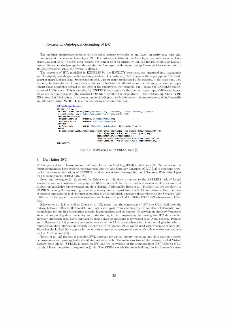
The modular architecture operates on a so-called gravity principle: at any layer, an entity may refer onlyto an entity at the same or lower layer [21]. For instance, entities at the Core layer may refer to other Coreclasses, as well as to Resource layer classes, but cannot refer to entities within the Interoperability or Domainlayers. The same principle applies also within the Core layer, in the sense that IfcKernel entities cannot refer toIfcCoreExtensions, while the reverse is allowed.
The concepts of IFC, modelled in EXPRESS by the ENTITY construct, are organised into taxonomiesvia the supertype/subtype partial ordering relation. For instance, IfcProcess is the supertype of IfcEvent,IfcProcedure and IfcTask. Some concepts (e.g. IfcProcess) are declared to be abstract, in the sense that theycan only be instantiated through their subtypes. Inheritance is allowed along the hierarchy, so that subtypesinherit those attributes defined at the level of the supertypes. For example, Fig.1 shows the EXPRESS specifi-cation of IfcProduct. This is modelled by ENTITY and stands for the abstract super-type of different classes,which are mutually disjoint (the construct ONEOF specifies the disjointness). The relationship SUBTYPEOF states that IfcProduct is subsumed under IfcObject. ObjectPlacement, Representation and ReferencedByare attributes, while WHERE is a rule specifying a certain condition.
Figure 1: IfcProduct in EXPRESS, from [6]
3 Owl-izing IFC
IFC supports data exchange among Building Information Modeling (BIM) applications [30]. Nevertheless, dif-ferent communities have explored its conversion into the Web Ontology Language (OWL) [33] to overcome draw-backs due to some limitations of EXPRESS, and to benefit from the exploitation of Semantic Web technologiesfor the management of BIM data [18].
Beetz and colleagues [3, 4], as well as Krima et al. [1], draw attention to the EXPRESS lack of formalsemantics, so that a logic-based language as OWL is preferable for the definition of axiomatic theories aimed atsupporting knowledge representation and data sharing. Additionally, Beetz et al. [4] stress that the popularity ofEXPRESS among the engineering community is very limited, apart from the STEP initiative, so that the reuseof existing ontologies or tools for interoperability is often inhibited, especially those related to the Semantic Webinitiative. In the paper, the authors explore a semiautomatic method for lifting EXPRESS schemas onto OWLfiles.
Schevers et al. [24] as well as Zhang et al [35], argue that the conversion of IFC into OWL facilitates thelinkage between different IFC models and databases, apart from enabling the exploitation of Semantic Webtechnologies for building information models. Katranuschkov and colleagues [13] develop an ontology frameworkaimed at supporting data modelling and data sharing in civil engineering by reusing the IFC data model.However, differently from other approaches, their library of ontologies is developed as an XML Schema. Pauwelsand colleagues [18, 19] present a conversion service of the XML-based schema into OWL ontologies in order torepresent building information through the enriched RDF graphs, which can be used with reasoning engines [19].Following the Linked Data approach, the authors stress the advantages of a semantic rule checking environmentfor the AEC domain [18].
Terkaj et al. [27] propose a modular OWL ontology for virtual factory modelling and data sharing betweenheterogeneous and geographically distributed software tools. The main structure of the ontology, called VirtualFactory Data Model (VFDM), is based on IFC and the conversion of the standard from EXPRESS to OWLmainly follows the pattern proposed in [3, 4]. The VFDM models the main building blocks of manufacturing
Towards an Ontological Grounding of IFC
38
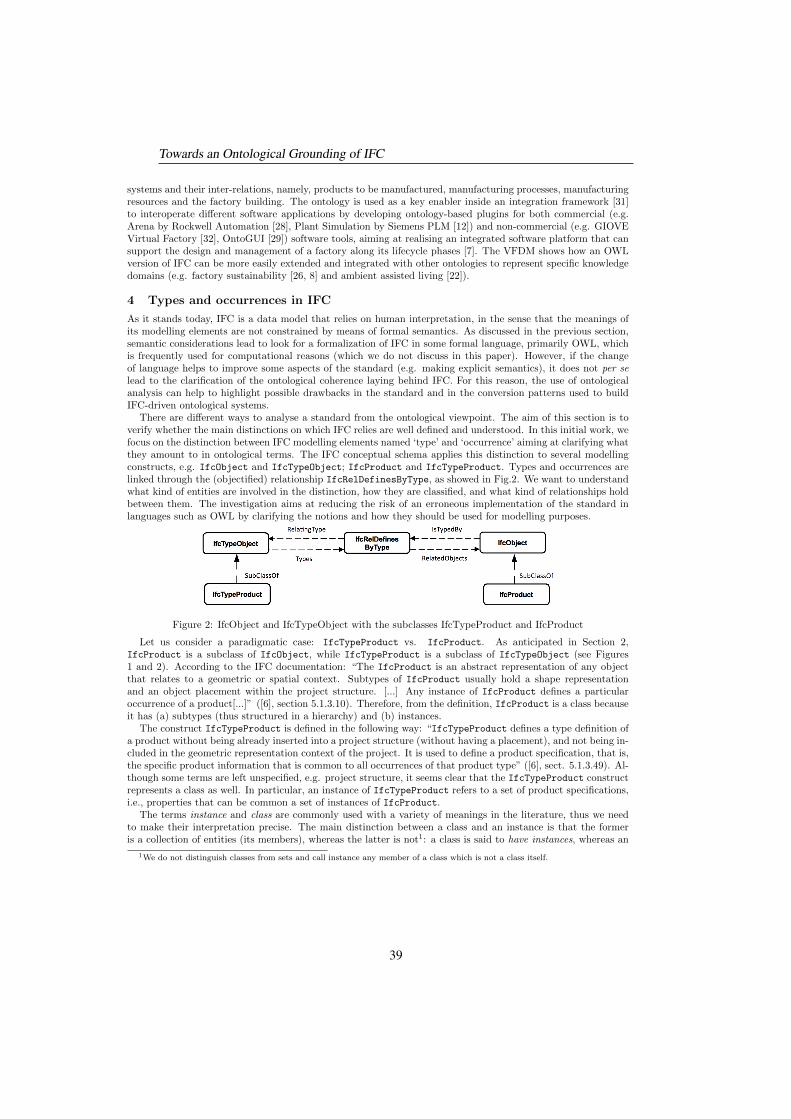
systems and their inter-relations, namely, products to be manufactured, manufacturing processes, manufacturingresources and the factory building. The ontology is used as a key enabler inside an integration framework [31]to interoperate different software applications by developing ontology-based plugins for both commercial (e.g.Arena by Rockwell Automation [28], Plant Simulation by Siemens PLM [12]) and non-commercial (e.g. GIOVEVirtual Factory [32], OntoGUI [29]) software tools, aiming at realising an integrated software platform that cansupport the design and management of a factory along its lifecycle phases [7]. The VFDM shows how an OWLversion of IFC can be more easily extended and integrated with other ontologies to represent specific knowledgedomains (e.g. factory sustainability [26, 8] and ambient assisted living [22]).
4 Types and occurrences in IFC
As it stands today, IFC is a data model that relies on human interpretation, in the sense that the meanings ofits modelling elements are not constrained by means of formal semantics. As discussed in the previous section,semantic considerations lead to look for a formalization of IFC in some formal language, primarily OWL, whichis frequently used for computational reasons (which we do not discuss in this paper). However, if the changeof language helps to improve some aspects of the standard (e.g. making explicit semantics), it does not per selead to the clarification of the ontological coherence laying behind IFC. For this reason, the use of ontologicalanalysis can help to highlight possible drawbacks in the standard and in the conversion patterns used to buildIFC-driven ontological systems.
There are different ways to analyse a standard from the ontological viewpoint. The aim of this section is toverify whether the main distinctions on which IFC relies are well defined and understood. In this initial work, wefocus on the distinction between IFC modelling elements named ‘type’ and ‘occurrence’ aiming at clarifying whatthey amount to in ontological terms. The IFC conceptual schema applies this distinction to several modellingconstructs, e.g. IfcObject and IfcTypeObject; IfcProduct and IfcTypeProduct. Types and occurrences arelinked through the (objectified) relationship IfcRelDefinesByType, as showed in Fig.2. We want to understandwhat kind of entities are involved in the distinction, how they are classified, and what kind of relationships holdbetween them. The investigation aims at reducing the risk of an erroneous implementation of the standard inlanguages such as OWL by clarifying the notions and how they should be used for modelling purposes.
Figure 2: IfcObject and IfcTypeObject with the subclasses IfcTypeProduct and IfcProduct
Let us consider a paradigmatic case: IfcTypeProduct vs. IfcProduct. As anticipated in Section 2,IfcProduct is a subclass of IfcObject, while IfcTypeProduct is a subclass of IfcTypeObject (see Figures1 and 2). According to the IFC documentation: “The IfcProduct is an abstract representation of any objectthat relates to a geometric or spatial context. Subtypes of IfcProduct usually hold a shape representationand an object placement within the project structure. [...] Any instance of IfcProduct defines a particularoccurrence of a product[...]” ([6], section 5.1.3.10). Therefore, from the definition, IfcProduct is a class becauseit has (a) subtypes (thus structured in a hierarchy) and (b) instances.
The construct IfcTypeProduct is defined in the following way: “IfcTypeProduct defines a type definition ofa product without being already inserted into a project structure (without having a placement), and not being in-cluded in the geometric representation context of the project. It is used to define a product specification, that is,the specific product information that is common to all occurrences of that product type” ([6], sect. 5.1.3.49). Al-though some terms are left unspecified, e.g. project structure, it seems clear that the IfcTypeProduct constructrepresents a class as well. In particular, an instance of IfcTypeProduct refers to a set of product specifications,i.e., properties that can be common a set of instances of IfcProduct.
The terms instance and class are commonly used with a variety of meanings in the literature, thus we needto make their interpretation precise. The main distinction between a class and an instance is that the formeris a collection of entities (its members), whereas the latter is not1: a class is said to have instances, whereas an
1We do not distinguish classes from sets and call instance any member of a class which is not a class itself.
Towards an Ontological Grounding of IFC
39
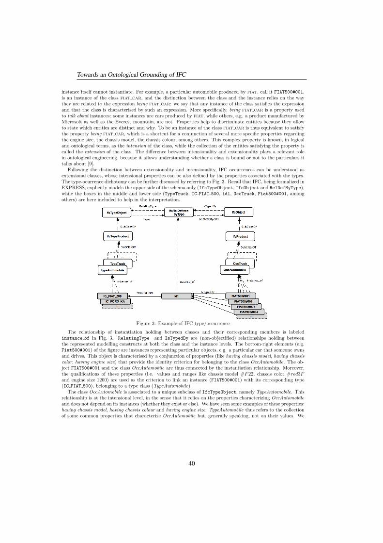
instance itself cannot instantiate. For example, a particular automobile produced by fiat, call it FIAT500#001,is an instance of the class fiat car, and the distinction between the class and the instance relies on the waythey are related to the expression being fiat car: we say that any instance of the class satisfies the expressionand that the class is characterised by such an expression. More specifically, being fiat car is a property usedto talk about instances: some instances are cars produced by fiat, while others, e.g. a product manufactured byMicrosoft as well as the Everest mountain, are not. Properties help to discriminate entities because they allowto state which entities are distinct and why. To be an instance of the class fiat car is thus equivalent to satisfythe property being fiat car, which is a shortcut for a conjunction of several more specific properties regardingthe engine size, the chassis model, the chassis colour, among others. This complex property is known, in logicaland ontological terms, as the intension of the class, while the collection of the entities satisfying the property iscalled the extension of the class. The difference between intensionality and extensionality plays a relevant rolein ontological engineering, because it allows understanding whether a class is bound or not to the particulars ittalks about [9].
Following the distinction between extensionality and intensionality, IFC occurrences can be understood asextensional classes, whose intensional properties can be also defined by the properties associated with the types.The type-ocurrence dichotomy can be further discussed by referring to Fig. 3. Recall that IFC, being formalized inEXPRESS, explicitly models the upper side of the schema only (IfcTypeObject, IfcObject and RelDefByType),while the boxes in the middle and lower side (TypeTruck, IC FIAT 500, id1, OccTruck, Fiat500#001, amongothers) are here included to help in the interpretation.
Figure 3: Example of IFC type/occurrence
The relationship of instantiation holding between classes and their corresponding members is labeledinstance of in Fig. 3. RelatingType and IsTypedBy are (non-objectified) relationships holding betweenthe represented modelling constructs at both the class and the instance levels. The bottom-right elements (e.g.Fiat500#001) of the figure are instances representing particular objects, e.g. a particular car that someone ownsand drives. This object is characterised by a conjunction of properties (like having chassis model, having chassiscolor, having engine size) that provide the identity criterion for belonging to the class OccAutomobile. The ob-ject FIAT500#001 and the class OccAutomobile are thus connected by the instantiation relationship. Moreover,the qualifications of these properties (i.e. values and ranges like chassis model #F22, chassis color #red3Fand engine size 1200) are used as the criterion to link an instance (FIAT500#001) with its corresponding type(IC FIAT 500), belonging to a type class (TypeAutomobile).
The class OccAutomobile is associated to a unique subclass of IfcTypeObject, namely TypeAutomobile. Thisrelationship is at the intensional level, in the sense that it relies on the properties characterizing OccAutomobileand does not depend on its instances (whether they exist or else). We have seen some examples of these properties:having chassis model, having chassis colour and having engine size. TypeAutomobile thus refers to the collectionof some common properties that characterize OccAutomobile but, generally speaking, not on their values. We
Towards an Ontological Grounding of IFC
40
call the relationship between the type and occurrence elements, i.e. the classes on the top of Fig. 3, typizationsince it allows to associate to each homogeneous collection of instances in the right hand-side of the diagram asingle general description, i.e. a set of properties in terms of which it is meaningful to consider a comparison ofinstances2.
Finally, an instance of TypeAutomobile, that is, an element in the bottom-left of Fig. 3, is associated witha collection of these very properties with specified values and ranges: in our example, having chassis model#F22, having chassis colour #red3F , having engine size 1200 and the like. We call this object IC FIAT 500. Inontological terms, IC FIAT 500 is called an information object. Also, we could call the relationship between thecollection of qualified properties IC FIAT 500 and the instance(s) FIAT500#001 that satisfies them a realizationsince the object FIAT500#001 manifests all the properties given by the information object IC FIAT 500 withthe requested qualifications. This relationship differs from that between the class TypeAutomobile and the classOccAutomobile: the first (realization) is between instances and says that an entity satisfies a set of propertieswith given values; the latter (typization) is between classes and associates the class corresponding to a set ofproperties (a type) to the occurrence class whose members must satisfy those properties for some admissiblevalue. Note that a realization does not need to be a physical entity; it may very well be a virtual element.
Currently, it is a matter of ambiguity whether an occurrence instance represents in IFC a physical entity (e.g.the car owned by someone), or a virtual representation in an information system. In our experience we notethat IFC practitioners adopt both readings depending on their application tasks. Note however that physicaland virtual entities have different ontological properties: on the one side, the former has e.g. a spatiotemporallocation according to which it can be classified as a physical object in a formal ontology framework like the oneproposed by the dolce foundational ontology [15]; on the other side, the latter lacks spatial location in theformer sense and is classified in dolce as an abstract object when it also lacks temporal location (in a commonsense perspective that is usually associated with physical objects); or as a concept when existing in time, forexample in the form of a description. Since physical, abstract and conceptual elements are distinguished bydistinct properties, an ontology artefact requires to clearly separate them. Note also that the identification ofclasses at the virtual (abstract) and the physical levels plays a relevant role in data sharing, communication andverification since it determines which data are affected by time and in which way. Consider a scenario in whicha practitioner develops an ontology-based instance model (A-Box) with an occurrence instance o1, which is avirtual entity. When a user accesses the ontology, s/he would not be able to properly interpret o1 as a virtualentity unless this is somehow modelled in the system by specific formal constraints. An explicit specificationof the ontological kind of entity that is represented (virtual or physical) could enhance the reliability of theinformation sources that use the standard.
5 Conclusion and further discussion
Current attempts towards the OWL formalization of IFC have not been systematically supported by the on-tological analysis of its terminology and modelling constructs. While bringing the benefits of formal semanticsinto IFC, OWL-ized IFC ontologies do not clarify the meanings of its modelling elements. Indeed, choosing howto interpret IFC notions relies on the users’ knowledge of the standard and their application needs, issues thatthreaten automated interoperability between IFC models developed by different communities. Our approachdiffers from the state of the art (Section 3), because it proposes a reading of the standard aimed at increasing itsontological soundness and conceptual clarity. The performed ontological analysis explains the type/occurrencemodelling pattern in terms of the difference between descriptions (i.e., information entities) within the typehierarchy, and their realizations within the occurrence hierarchy, where realizations might be both physical andvirtual elements in the system.
The distinction between IFC types and occurrence classes should not be confused with the distinction betweenmeta-classes and classes [16]. Briefly said, meta-classes and classes differ on the abstraction level: the meta-classhas the class as an instance. Yet, if a class instantiates a meta-class, then the meta-class should be associatedwith a collection of the properties that are necessary for a class to be classified as an instance. Accordingto our analysis, TypeAutomobile is related to OccAutomobile via properties like having chassis model, havingchassis colour and having engine size. However, these properties do not necessarily have to be linked to theproperties of the class OccAutomobile for two reasons. First, IFC allows that some properties associated withtypes can be overridden [6], thus they are not treated as necessary properties. Second, analogous to the example
2Ontologically speaking, we could say that IFC is a contextual modelling framework since the notion of ‘homogeneous instances’depends on the user or the application task. This observation is crucial for a suitable choice of the classes to consider in the diagram.
Towards an Ontological Grounding of IFC
41
of IfcBuilding [6], which does not need to have specified IfcBuildingType, it is possible to have an instance ofclass OccAutomobile and directly characterize it with as many properties as possible (i.e. chassis et al.) withoutlinking it to any instance of class TypeAutomobile. This example, together with the possibility to override someproperties associated with the types, demonstrate that the standard currently does not treat the IFC types asmeta-classes of the occurrence classes. Accordingly, the Instance of relationship does not apply to types andclasses of occurrences in IFC.
The difference between IFC type and occurrence classes may remind the materialization modelling pattern [20].Materialization is a binary relationship holding between abstract and concrete entities, e.g. between the abstractCarModel and the concrete Car, where the former is a class of properties, and the latter is a class of particularautomobiles defined by the class of properties. Concrete classes are said to materialise abstract ones; e.g. onecould say that John’s and Mary’s Fiat500s materialize the same Fiat500 model, although they are two differentparticular cars. However, the abstract-concrete pairs, and thus the materialization relationships, are ambiguouslydefined: firstly, materialization holds that one and the same thing can be both concrete and abstract [20] whileontological theories force to distinguish them as different kinds [15]. Secondly, the semantics of the materializationrelationship is defined through the instantiation and generalization/specialization relationships (together with ametaclass/class correspondence), but generalization and abstraction are quite different operators, similarly forspecialization and concretization. It remains unclear how abstract and concrete entities are related by theseoperators. The study of materialization might enlighten the IFC type/occurrence dichotomy; nevertheless, thiscan be assessed only once the semantics of materialization has become conceptually transparent and (possibly)formally represented.
Acknowledgments
This research has been partially funded by MIUR under the Italian flagship project “Fabbrica del Futuro”, Sub-project 2, research project “Product and Process Co-Evolution Management via Modular Pallet configuration”(PRO2EVO).
References
[1] R. Barbau, S. Krima, S. Rachuri, A. Narayanan, X. Fiorentini, S. Foufou, and R.D. Sriram, “OntoSTEP:Enriching product model data using ontologies,” in Computer-Aided Design, 44(6):575–590, 2012.
[2] V. Bazjanac and D.B. Crawley, “The implementation of Industry Foundation Classes in simulationtools for the building industry,” tech. rep., Lawrence Berkeley National Laboratory, 1997.
[3] J. Beetz, J. van Leeuwen, and B. de Vries, “An Ontology Web Language notation of the IndustryFoundation Classes,” in 22nd CIB W78 Conference on Information Technology in Construction, 2005.
[4] J. Beetz, J. Leeuwen, and B. Vries, “IfcOwl: A case of transforming express schemas into ontologies,”Artificial Intelligence for Engineering Design, Analysis and Manufacturing, vol. 23, pp. 89–101, 2009.
[5] S. Borgo, M. Carrara, P. Garbacz, and P. E. Vermaas, “A formalization of functions as operations onflows,” Journal of Computing and Information Science in Engineering, 11(3):031007 1–14, 2011.
[6] buildingSMART International, “Industry Foundation Classes. IFC release candidate 4,” 1999-2012.
[7] M. Colledani, G. Pedrelli, W. Terkaj, and M. Urgo, “Integrated virtual platform for manufacturingsystems design,” Procedia CIRP, vol. 7, pp. 425–430, 2013.
[8] S. Gagliardo, F. Giannini, M. Monti, G. Pedrielli, W. Terkaj, M. Sacco, M. Ghellere, F. Salamone,“An Ontology-based Framework for Sustainable Factories,” Computer-Aided Design and Applications,vol. 12(2):198–207, 2015.
[9] N. Guarino and C. Welty, “An overview of OntoClean,” in Handbook on Ontologies (S.Staab andR.Studer, eds.), pp. 201–220, Springer-Verlag Berlin Heidelberg, 2009.
[10] M. Grueninger, “Using the PSL ontology,” in Handbook on Ontologies (S.Staab and R.Studer, eds.),pp. 423–443, Springer-Verlag Berlin Heidelberg, 2009.
Towards an Ontological Grounding of IFC
42
[11] ISO, Industrial Automation Systems and Integration - Product Data Representation and Exchange. Part11: Description methods: The EXPRESS language reference manual, iso 10303-11:2004(e) ed., 2004.
[12] B. Kadar, W. Terkaj, and M. Sacco, “Semantic Virtual Factory supporting interoperable modelling andevaluation of production systems,” CIRP Annals - Manufacturing Technology, 62(1):443–446, 2013.
[13] P. Katranuschkov, A. Gehre, and R. Scherer, “An ontology framework to access IFC model data,”ITcon, vol. 8, no. Special Issue, pp. 413–437, 2003.
[14] L. Khemlani, “The IFC building model: A look under the hood,” 2004.
[15] C. Masolo, S. Borgo, A. Gangemi, N. Guarino, A. Oltramari, “WonderWeb Deliverable D18, OntologyLibrary (final)”. LOA-ISTC, CNR, Tech. Rep. 2003
[16] J. Mylopoulos, A. Borgida, M. Jarke, M. Koubarakis, “TELOS: Representing knowledge about infor-mation systems”, in ACM Transactions on Information Systems (TOIS), 8(4), pp. 325-362.
[17] National Institute of Building Sciences, “National building information modeling standard, version 1 –part 1: Overview, principles and methodologies,” tech. rep., 2007.
[18] P. Pauwels, D. Van Deursen, R. Verstraeten, J. De Roo, R. De Meyer, R. Van de Walle, and J. VanCampenhout, “A semantic rule checking environment for building performance checking” in Automationin Construction, vol. 20:5, pp. 506–518, 2011.
[19] P. Pauwels and D. Van Deursen ,“IFC/RDF: Adaptation, Aggregation and Enrichment”, in FirstInternational Workshop on Linked Data in Architecture and Construction (LDAC 2012), 2012
[20] A.Pirotte, E.Zimanyi, D.Massart, T.Yakusheva, Materialization: A Powerful and Ubiquitous Abstrac-tion Pattern, in Proceedings of the 20th International Conference on Very Large Data Bases (VLDB),1994
[21] L.C. Pouchard and A.F. Cutting-Decelle, “Ontologies and standard-based approaches to interoperabil-ity for concurrent engineering” in Concurrent Engineering in Construction Projects, Taylor & Francis2007
[22] M. Sacco, E. Caldarola, G. Modoni, W. Terkaj, “Supporting the Design of AAL through a SWIntegration Framework: The D4All Project,” in Universal Access in Human-Computer Interaction.Design and Development Methods for Universal Access, Lecture Notes in Computer Science, vol. 8513,pp. 75-84, Springer International Publishing, 2014.
[23] E.M. Sanfilippo, S. Borgo, and C. Masolo. States, events, activities: Is there an ontology behindBPMN? In International Conference on Formal Ontology in Information Systems (FOIS 2014), FAIA,IOS Press, 2014.
[24] H. Schevers and R. Drogenmuller, “Converting the industry foundation classes to the web ontologylanguage,” in First International Conference on Semantics, Knowledge and Grid (SKG), 2006.
[25] S. Szykman, R.D. Sriram, and W.C. Regli, “The role of knowledge in next-generation product devel-opment systems,” in Journal of Computing and Information Science in Engineering, vol. 1, pp. 3–11,2001.
[26] W. Terkaj, L. Danza, A. Devitofrancesco, S. Gagliardo, M. Ghellere, F. Giannini, M. Monti, G. Pedrielli,M. Sacco, and F. Salamone, “A Semantic Framework for Sustainable Factories,” in Procedia CIRP,vol. 17, pp. 547–552, 2014.
[27] W. Terkaj, G. Pedrelli, and M. Sacco, “Virtual Factory Data Model,” in Workshop on Ontology andSemantic Web for Manufacturing OSEMA 2012, CEUR Workshop Proceedings, vol. 886, pp. 29–43,2012.
[28] W. Terkaj and M. Urgo, “Virtual Dactory Data Model to support performance evaluation of produc-tion systems,” in Workshop on Ontology and Semantic Web for Manufacturing OSEMA 2012, CEURWorkshop Proceedings, vol. 886, pp. 44–58, 2012.
Towards an Ontological Grounding of IFC
43
[29] W. Terkaj and M. Urgo, “Ontology-based modeling of production systems for design and performanceevaluation,” in Proceedings of 12th IEEE International Conference on Industrial Informatics (INDIN),pp. 748–753, 2014.
[30] V. Thein, “Industry Foundation Classes (IFC).BIM interoperability through a vendor-independent fileformat. a bentley white paper,” tech. rep., Bentley. Sustaining Infrastructure, 2011.
[31] T. Tolio, M. Sacco, W. Terkaj, and M. Urgo, “ Virtual Factory: an Integrated Framework for Manu-facturing Systems Design and Analysis,” in Procedia CIRP, vol. 7, pp. 425–430, 2013.
[32] G.P. Vigano, L. Greci, S. Mottura, and M. Sacco, “Giove Virtual Factory: A new viewer for a moreimmersive role of the user during factory design,” in Digital Factory for Human-oriented ProductionSystems. The Integration of International Research Projects, pp. 201–216, Springer London, 2011.
[33] W3C OWL Working Group, “OWL 2, Web Ontology Language document overview (second edition).”
[34] M. West, Developing High Quality Data Models. Morgan Kaufmann, 2011.
[35] L. Zhang and R. R. Issa, “Development of IFC-based construction industry ontology for informationretrieval from ifc models” in EG-ICE Workshop, University of Twente, The Netherlands, July. 2011.
Towards an Ontological Grounding of IFC
44
Ontologies in Enterprise Applications:
Dimensional Comparison
Valeria de Paiva, William Jarrold, David Martin,Peter F. Patel-Schneider, Karen Wallace, Peter Z. Yeh
Nuance CommunicationsSunnyvale, CA 94085 U. S. A
Abstract
Many important categories of applications such as information integra-tion, data analytics, and personal assistance require access to a generalstore of knowledge. The usefulness of such a store depends not onlyon its factual content, but also on its conceptual framework, or ontol-ogy. Ontologies vary markedly in their characteristics, and the value ofan ontology varies according to the purpose for which it will be used.Thus, selecting one or more ontologies suitable for an application canbe challenging. We have created a set of dimensions to consider whenmaking this selection. Although these dimensions are motivated by theneeds of conversational assistance applications, they can benefit thedevelopment of a wide variety of enterprise applications. We appliedthese dimensions to four large, general-purpose ontologies—Cyc, Free-base, SUMO, and YAGO—and made qualitative comparisons betweenthem.
General-purpose ontologies are playing an increasingly central role in many important categories of appli-cations such as information integration, distributed knowledge management, data analytics, and personal as-sistance. These ontologies aim to provide a framework for better organization and access of data, effectiveinformation and knowledge sharing, reliable information exchange, and improved coordination between distinctorganizations or among members of the same organization. Consequently, companies face an increasing need tobe able to choose the most suitable ontologies for their applications. This paper addresses that need.
We aim to provide an evaluative framework that may be applied to assess the usefulness of an ontology for anyparticular commercial application. Specifically, we set out to define the dimensions under which ontologies can becompared, and focus on those dimensions that assess terminological knowledge (definitions of concepts and theirproperties and relationships), not assertional knowledge (instances of concepts and facts about them). This focusis warranted because treatments of terminological knowledge are often overshadowed by assertional knowledge,or overlooked altogether. We believe our dimensions can provide an evaluative framework for comparing thestrengths and weaknesses of different ontologies, which may prove useful for others investigating a robust use ofsemantic knowledge.
Our dimensions have resulted from our investigation of different ontologies suitable for conversational systems,as described in Kaplan’s “Beyond the GUI: It’s Time for a Conversational User Interface” [6], and are exemplifiedby our end-to-end speech-driven second screen application for television program discovery, described in [14].Despite our focus application, we believe that our dimensions and our preliminary results from applying themshould be applicable to a wide variety of companies that need to make the best choice for their applications.
In: Vinay Chaudhri, Alexandre Rademaker (eds.): Proceedings of the Workshop on Formal Ontologies meet Industry (FOMI), Riode Janeiro, Brazil, 22-Sep-2014, published at http://ceur-ws.org
45
This is because of the extremely broad range of requirements of conversational systems. A conversationalsystem is more than just speech recognition and synthesized speech; it must combine these voice technologieswith natural-language understanding of the intention behind those spoken words. The intelligence comes fromcontextual awareness (who said what, when and where), perceptive listening (automatically waking up when youspeak), and artificial intelligence reasoning. Moreover, a conversational system needs to be capable of questionanswering, intent recognition, semantic database integration, proactive behavior and even social intelligence.
Much work has been done in comparing and evaluating ontologies, especially devising quantitative metrics forontologies using OWL as their representation language [13, 3, 12]. [13] characterizes most prior work as focusingon the mere structural aspects of an ontology and not considering the semantics of the ontology. Our paper sharesthe goal of semantic focus, but because our scope is more general in the kinds of languages we want to compare(i.e.not only OWL-based) it is less formal, and we actually apply our evaluation strategy to four ontologies.The goals and motivations of [10] are similar to ours, they provide a broad overview and discussion of issues inontology evaluation, and approaches that may be used. While [10] touches on some of the same dimensions thatwe identify, it does not propose a specific set of dimensions that make up an evaluative framework. Since itsfocus is on approaches and specific evaluations from the life sciences literature, it does not give a comparativeevaluation of specific ontologies as we have done. Similarly, we share with the work on OntoQA [12] the goalof general-purpose ontologies, the idea that one should have independent metrics for schemas, knowledge bases(KBs) and classes, but we concentrate efforts on qualitative dimensions for the schemas, while they concentrateon a specific system to measure OWL-based ontologies.
We subjected four general-purpose ontologies to our dimension-based comparison: ResearchCyc [8], Freebase[2],1 SUMO [9], and YAGO [11, 5]. Resource constraints limited the number to four. Our analysis, and thenumbers we report, are for these systems as they existed in early 2014. We chose these particular four systemsbecause they are among the most prominent large, general-purpose, broad-coverage ontologies. They also takequite different approaches to modelling the world. Cyc is a long-standing project to assemble a comprehensiveontology and knowledge base of everyday common sense knowledge, with the goal of enabling AI applicationsto perform human-like reasoning. The Suggested Upper Merged Ontology (SUMO) and its domain ontologiesform a large formal, open-source ontology with significant numbers of definitional axioms and rules. YAGO isa knowledge base developed at the Max Planck Institute for Computer Science in Saarbrucken, automaticallyextracted from Wikipedia, WordNet and other sources. Freebase is a large collaborative knowledge base consistingof metadata composed mainly by its community members. It is an online collection of structured data harvestedfrom many sources, including individual ‘wiki’ contributions. Freebase aims to create a global resource whichallows people (and machines) to access common information more effectively. Google’s Knowledge Graph ispowered, in part, by Freebase.
We also looked at the DBpedia [7] ontology and schema.org, http://schema.org, two other efforts that mightbe considered to be general-purpose ontologies. However, both of these were immediately seen to be unsuitablefor our needs, as they are both comparatively small and inexpressive. As well, the meaning of constructs inschema.org is very hard to determine. This is not to say that the data available from DBpedia or the datadescribed by schema.org markup would not be valuable, just that their ontologies are too limited to form thebackground ontology necessary for general conversational systems.
We first discuss the dimensions of comparison that we found useful when comparing the ontological schemasexemplified by the four chosen knowledge repositories. How the four compared in each one of these dimensionsforms the basis for the matrix shown in table 1. We then discuss the main points or lessons learned from theseone-by-one comparisons.
1 Ontology Evaluation Dimensions
Most knowledge repositories consist of three main components that are of interest to real-world applications: theontology (i.e., schema, axioms, etc.), the representation language, and the data (i.e., instances of entity types inthe ontology). These components are equally important, but our focus in this paper is on the ontology, which
• provides a scaffolding to organize data of interest to an application, and
1After we did our comparison, Google announced that Freebase will be discontinued in mid-2015, and that Google will providea tool to help users add Freebase content to Wikidata (http://www.wikidata.org). We hope that users will transition most Freebasecontent to Wikidata and that the ontology supporting Wikidata will also grow into a general-purpose ontology on par with theontologies in SUMO and ResearchCyc.
Ontologies in Enterprise Application: Dimensional Comparison
46
• supports the inferences over the data required by the application.
We propose ten dimensions for evaluating the utility of an ontology with respect to the above roles. Thesedimensions are inspired by those from data quality [1], but have been modified (and extended) for ontologies.We intend for these dimensions to provide a common yardstick for comparison across the ontologies of differentknowledge repositories.
Domain Breadth: What is the breadth of domains covered by the ontology? For example, does the ontologycover a single domain such as geography or multiple domains ranging from entertainment to pathology? Broaddomain breadth is important for applications that need to support a wide range of domains, such as virtualassistants.
Axiomatic Depth: Is the ontology complete in terms of the entity types, relations, and axioms for eachdomain covered? Axiomatic depth is orthogonal to domain breath, and is important for applications that focuson specialized domains such as healthcare, finance, etc.
Accuracy: How accurately do the entity types, relations, and axioms in the ontology reflect the real-worldobjects and domains they represent? Accuracy directly impacts the organizational quality of the data used byan application and the validity of any inferences over the data.
Consistency: Are there contradictions or incompatibilities in the ontology, e.g. contradicting axioms, in-compatible generalizations, etc. If so, then how pervasive are these contradictions and incompatibilities? Likeaccuracy, consistency impacts data organization and inference validity. We note that it is impractical to expecta large ontology to have no inconsistency. Hence, this dimension is not intended to be binary. Instead, the intentis to provide a measure on the degree of consistency observed.
Integrity: Are the basic relations and axioms (e.g., generalization, instance, disjointness, selectional restric-tions, etc.) present in the ontology? Have they been codified, or are they captured only in documentationand comments? Integrity is critical in enabling many common types of inference (e.g. subsumption, constraintviolation, etc.) required by real-world applications, and can be viewed as axiomatic depth applied to the basicrelations and axioms of an ontology.
Uniformity: Are the entity types and relations in the ontology used in a uniform manner? Do these usesconform with the semantics of the types and relations? Uniformity reduces the likelihood of modeling errors andhence the organizational quality of the data. Uniformity also improves the maintainability of an ontology andhence the maintainability of applications that use the ontology.
Redundancy: Are there redundancies in the ontology? For example, an ontology may have multiple entitytypes and relations for representing time, or generalizations that share similarities as well as differences. Re-dundancy is orthogonal to uniformity, and hence increases the difficulty in maintaining and using the ontology.Moreover, redundancy can result in unanticipated inference behaviors or invalid inference results.
Granularity: How granular are the entity types and relations in the ontology? An ontology that is toocoarse (e.g. every type is a specialization of Thing) is not ideal. Neither is an ontology that is too fine-grained,e.g. an ontology with types like Person-from-California, a subclass of Person. Ontologies that are too coarse orfine-grained are difficult to extend, and hence less desirable for applications requiring additional customization.
Timeliness: How frequently is the ontology updated to reflect changes in the real-world objects and domainsit represents? For example, how much time typically elapses for a pathology ontology to be updated when anew virus is discovered? Timeliness can be viewed as accuracy over time, and is important for applications thatoperate in dynamic domains.
Stability: How frequently is the ontology changed to fix mistakes, re-organized for efficiency purposes, etc?Stability directly impacts the maintainability of the applications that use the ontology.
2 Comparison Between Ontologies
We applied the dimensions outlined above to the ontologies (i.e. schemata) of four well-known knowledge reposi-tories (i.e., YAGO, SUMO, Freebase, and ResearchCyc) as part of a preliminary comparison. We emphasize thatour comparison focuses on the ontologies of the selected knowledge repositories, not the data or representationlanguages. Table 1 shows the qualitative findings that we observed from this comparison. Additional qualitativeobservations and remarks along the most salient dimensions for each ontology can be found in their respectivesubsections below.
We note that the findings presented are not based on a formal, rigorous evaluation and should be treatedas qualitative observations suitable for high-level guidance. Thus, given the preliminary nature of our work,additional effort is needed such as providing more quantitative characterizations of the ratings for each dimension.
Ontologies in Enterprise Application: Dimensional Comparison
47
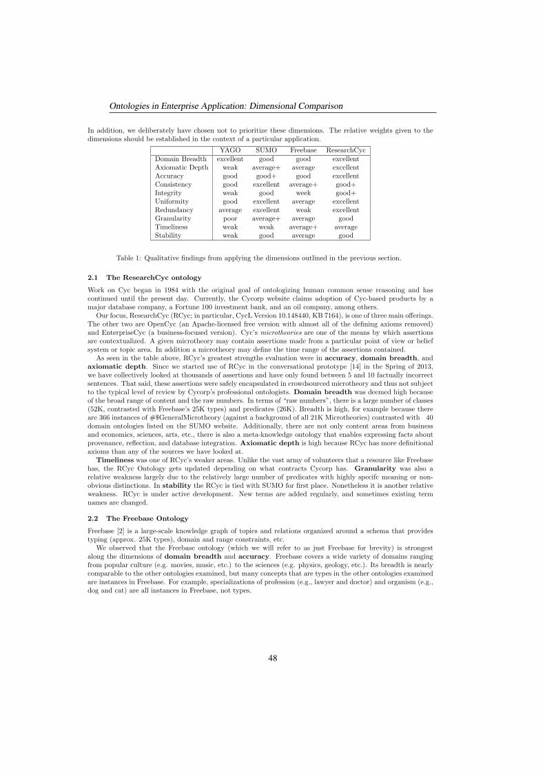
In addition, we deliberately have chosen not to prioritize these dimensions. The relative weights given to thedimensions should be established in the context of a particular application.
YAGO SUMO Freebase ResearchCycDomain Breadth excellent good good excellentAxiomatic Depth weak average+ average excellentAccuracy good good+ good excellentConsistency good excellent average+ good+Integrity weak good week good+Uniformity good excellent average excellentRedundancy average excellent weak excellentGranularity poor average+ average goodTimeliness weak weak average+ averageStability weak good average good
Table 1: Qualitative findings from applying the dimensions outlined in the previous section.
2.1 The ResearchCyc ontology
Work on Cyc began in 1984 with the original goal of ontologizing human common sense reasoning and hascontinued until the present day. Currently, the Cycorp website claims adoption of Cyc-based products by amajor database company, a Fortune 100 investment bank, and an oil company, among others.
Our focus, ResearchCyc (RCyc; in particular, CycL Version 10.148440, KB 7164), is one of three main offerings.The other two are OpenCyc (an Apache-licensed free version with almost all of the defining axioms removed)and EnterpriseCyc (a business-focused version). Cyc’s microtheories are one of the means by which assertionsare contextualized. A given microtheory may contain assertions made from a particular point of view or beliefsystem or topic area. In addition a microtheory may define the time range of the assertions contained.
As seen in the table above, RCyc’s greatest strengths evaluation were in accuracy, domain breadth, andaxiomatic depth. Since we started use of RCyc in the conversational prototype [14] in the Spring of 2013,we have collectively looked at thousands of assertions and have only found between 5 and 10 factually incorrectsentences. That said, these assertions were safely encapsulated in crowdsourced microtheory and thus not subjectto the typical level of review by Cycorp’s professional ontologists. Domain breadth was deemed high becauseof the broad range of content and the raw numbers. In terms of “raw numbers”, there is a large number of classes(52K, contrasted with Freebase’s 25K types) and predicates (26K). Breadth is high, for example because thereare 366 instances of #$GeneralMicrotheory (against a background of all 21K Microtheories) contrasted with 40domain ontologies listed on the SUMO website. Additionally, there are not only content areas from businessand economics, sciences, arts, etc., there is also a meta-knowledge ontology that enables expressing facts aboutprovenance, reflection, and database integration. Axiomatic depth is high because RCyc has more definitionalaxioms than any of the sources we have looked at.
Timeliness was one of RCyc’s weaker areas. Unlike the vast army of volunteers that a resource like Freebasehas, the RCyc Ontology gets updated depending on what contracts Cycorp has. Granularity was also arelative weakness largely due to the relatively large number of predicates with highly specifc meaning or non-obvious distinctions. In stability the RCyc is tied with SUMO for first place. Nonetheless it is another relativeweakness. RCyc is under active development. New terms are added regularly, and sometimes existing termnames are changed.
2.2 The Freebase Ontology
Freebase [2] is a large-scale knowledge graph of topics and relations organized around a schema that providestyping (approx. 25K types), domain and range constraints, etc.
We observed that the Freebase ontology (which we will refer to as just Freebase for brevity) is strongestalong the dimensions of domain breadth and accuracy. Freebase covers a wide variety of domains rangingfrom popular culture (e.g. movies, music, etc.) to the sciences (e.g. physics, geology, etc.). Its breadth is nearlycomparable to the other ontologies examined, but many concepts that are types in the other ontologies examinedare instances in Freebase. For example, specializations of profession (e.g., lawyer and doctor) and organism (e.g.,dog and cat) are all instances in Freebase, not types.
Ontologies in Enterprise Application: Dimensional Comparison
48
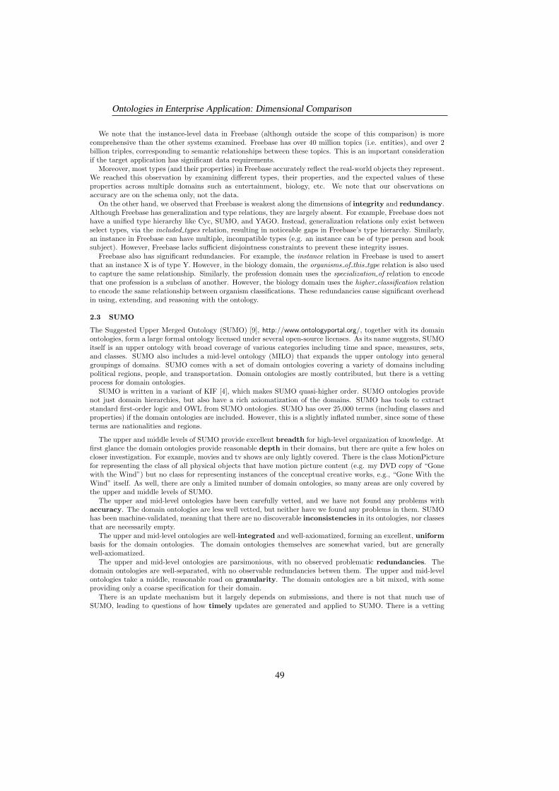
We note that the instance-level data in Freebase (although outside the scope of this comparison) is morecomprehensive than the other systems examined. Freebase has over 40 million topics (i.e. entities), and over 2billion triples, corresponding to semantic relationships between these topics. This is an important considerationif the target application has significant data requirements.
Moreover, most types (and their properties) in Freebase accurately reflect the real-world objects they represent.We reached this observation by examining different types, their properties, and the expected values of theseproperties across multiple domains such as entertainment, biology, etc. We note that our observations onaccuracy are on the schema only, not the data.
On the other hand, we observed that Freebase is weakest along the dimensions of integrity and redundancy.Although Freebase has generalization and type relations, they are largely absent. For example, Freebase does nothave a unified type hierarchy like Cyc, SUMO, and YAGO. Instead, generalization relations only exist betweenselect types, via the included types relation, resulting in noticeable gaps in Freebase’s type hierarchy. Similarly,an instance in Freebase can have multiple, incompatible types (e.g. an instance can be of type person and booksubject). However, Freebase lacks sufficient disjointness constraints to prevent these integrity issues.
Freebase also has significant redundancies. For example, the instance relation in Freebase is used to assertthat an instance X is of type Y. However, in the biology domain, the organisms of this type relation is also usedto capture the same relationship. Similarly, the profession domain uses the specialization of relation to encodethat one profession is a subclass of another. However, the biology domain uses the higher classification relationto encode the same relationship between organism classifications. These redundancies cause significant overheadin using, extending, and reasoning with the ontology.
2.3 SUMO
The Suggested Upper Merged Ontology (SUMO) [9], http://www.ontologyportal.org/, together with its domainontologies, form a large formal ontology licensed under several open-source licenses. As its name suggests, SUMOitself is an upper ontology with broad coverage of various categories including time and space, measures, sets,and classes. SUMO also includes a mid-level ontology (MILO) that expands the upper ontology into generalgroupings of domains. SUMO comes with a set of domain ontologies covering a variety of domains includingpolitical regions, people, and transportation. Domain ontologies are mostly contributed, but there is a vettingprocess for domain ontologies.
SUMO is written in a variant of KIF [4], which makes SUMO quasi-higher order. SUMO ontologies providenot just domain hierarchies, but also have a rich axiomatization of the domains. SUMO has tools to extractstandard first-order logic and OWL from SUMO ontologies. SUMO has over 25,000 terms (including classes andproperties) if the domain ontologies are included. However, this is a slightly inflated number, since some of theseterms are nationalities and regions.
The upper and middle levels of SUMO provide excellent breadth for high-level organization of knowledge. Atfirst glance the domain ontologies provide reasonable depth in their domains, but there are quite a few holes oncloser investigation. For example, movies and tv shows are only lightly covered. There is the class MotionPicturefor representing the class of all physical objects that have motion picture content (e.g. my DVD copy of “Gonewith the Wind”) but no class for representing instances of the conceptual creative works, e.g., “Gone With theWind” itself. As well, there are only a limited number of domain ontologies, so many areas are only covered bythe upper and middle levels of SUMO.
The upper and mid-level ontologies have been carefully vetted, and we have not found any problems withaccuracy. The domain ontologies are less well vetted, but neither have we found any problems in them. SUMOhas been machine-validated, meaning that there are no discoverable inconsistencies in its ontologies, nor classesthat are necessarily empty.
The upper and mid-level ontologies are well-integrated and well-axiomatized, forming an excellent, uniformbasis for the domain ontologies. The domain ontologies themselves are somewhat varied, but are generallywell-axiomatized.
The upper and mid-level ontologies are parsimonious, with no observed problematic redundancies. Thedomain ontologies are well-separated, with no observable redundancies betwen them. The upper and mid-levelontologies take a middle, reasonable road on granularity. The domain ontologies are a bit mixed, with someproviding only a coarse specification for their domain.
There is an update mechanism but it largely depends on submissions, and there is not that much use ofSUMO, leading to questions of how timely updates are generated and applied to SUMO. There is a vetting
Ontologies in Enterprise Application: Dimensional Comparison
49
mechanism for all updates to the ontology, leading to good stability. However, there is not a full formal processfor checking that updates are reasonable.
In summary, SUMO and its domain ontologies form a good, well-axiomatized broad-coverage ontology. Wewere most impressed with the care that has gone into the upper and mid levels of SUMO, which provides anexcellent scaffolding for general organization of knowledge. However, SUMO is much less useful at lower levels.There are not that many domains covered and even those that are covered are not always covered in sufficientdetail for use as a core domain in a system.
2.4 The YAGO Ontology
YAGO, of which YAGO2s is the current release, is derived from Wikipedia, WordNet, and GeoNames. It is ahuge semantic knowledge base in terms of the numbers of classes, entities, and facts, but defines a relatively smallnumber of properties — about 100 properties for facts extracted from Wikipedia, a small number for capturingtemporal and geospatial data, and several for capturing contextual (provenance) information. Roughly speaking,the upper level classes of YAGO correspond to synsets from WordNet, and the lower level classes correspondto Wikipedia categories. As of March 2011, YAGO had 292,070 classes based on Wikipedia categories, 68,446classes based on WordNet synsets, 642 GeoNames-based classes, and 53 of its own classes. (These statistics referto the YAGO release available at that time.)
For our purposes, the characteristics of YAGO are dependent on the nature of its three sources, and the limitedontological structuring provided by those three sources. YAGO naturally ranks high on domain breadth, dueto the encyclopedic breadth of both Wikipedia and WordNet. It ranks high on accuracy, consistency, anduniformity, partly because of the high quality of those sources, and partly because of the high quality of itsapproach to data extraction. However, these high rankings are also partly due to the simplicity of what YAGOtries to express. In other words, because the bulk of the YAGO ontology is the class taxonomy, along with thesmall number of properties mentioned above, there aren’t too many opportunities for mistakes along these threedimensions.
At the same time, this limited expressiveness of the ontology is reflected in a low score on the dimensionsof axiomatic depth and integrity. The Wikipedia categories are often idiosyncratic, e.g., “Catalan handballclubs” and “Hotels established in 1806”. Except for the taxonomic relations that YAGO determines for them,they are not axiomatized (that is, they have no properties directly associated with them). Although it is truethat such categories carry information understandable by a human reader, that information is not accessible toa computational system without the creation of additional axioms. This could involve a large effort in manualannotation and/or further research on algorithms for extracting meaning from Wikipedia text. WordNet is notwell structured for reasoning purposes, and has only minimal axiomatization. (Furthermore, some WordNetproperties, such as meronym and holonym, are not present in YAGO.)
YAGO’s ratings on granularity and redundancy are also directly related to the nature of its sources. Forour purposes, granularity is particularly problematic. With over 360,000 concepts, there is a great deal ofclutter; that is, concepts that are unlikely to be directly employed, such as the Wikipedia categories mentionedabove.. In addition, most instances in YAGO have many types — some corresponding to Wikipedia categoriesand others corresponding to WordNet senses — and there appears to be no robust automated way to identifythe most useful type(s) for the kinds of use cases we have in mind.
Finally, YAGO’s low ratings on timeliness and stability are simply due to the small number of releases sinceits inception, the possibility of non-incremental exploration of future directions, and its status as an academicresearch effort with only a small community of contributors.
3 Analysis
The four ontologies we examined fall into two camps. The Freebase and YAGO ontologies are relatively inex-pressive, containing little more than generalization relationships and role typing. The Cyc ontology and SUMOare much richer, with disjointness and many other axioms that define the concepts and relationships in theontologies.
Of course, if you don’t care too much about this extra information, or cannot utilize it, the added computa-tional costs in working with expressive ontologies may be daunting. For example, if you are concerned with simpleaccess to information (i.e., your application performs retrievals over data), then you probably only need simpletyping, and the Freebase ontology would be a reasonable choice, particularly as Freebase contains a large amount
Ontologies in Enterprise Application: Dimensional Comparison
50
of data. In this scenario, the Freebase ontology’s issues with redundancy, integrity, and uniformity become lesscritical, because you are only returning retrievals for further analysis by humans, or for import into some otherontological framework. However, even in this scenario you can run into difficulties; for example, the two differentrelationships for birth date in Freebase—one for persons and one for non-human animals—makes even simpleinformation access more difficult, showcasing a problem caused by Freebase’s lack of uniformity. YAGO can besimilarly used as a simple information source, but is less versatile in that, although it covers many domains, itsontology says very little about each of them (that is, it defines a much smaller number of properties).
However, if you need to perform reasoning over information, such as we envision in a conversational system toimplement general user requests in terms of a knowledge repository, then the extra organizational power of Cycand SUMO is extremely useful. Along with this extra power, Cyc and SUMO are better in terms of accuracy,consistency, and integrity, all important in a reasoning setting because incorrect information is magnified duringreasoning. Between SUMO and Cyc, we prefer the Cyc ontology because it covers more domains and provides amore complete organization of many of these domains.
In some sense, any large system is going to have to interact with several ontological setups, as it will be pullinginformation from several sources, and the different sources are very likely to have different organizations of theirinformation. This again argues for a powerful ontological system, one that can axiomatize the relationshipsbetween its organization and the organization of the other ontology.
On a final note, different ontologies, and data sources, come with different licenses. The licenses of someof the freely-available ontologies may cause problems in an industrial setting and these need to be consideredseparately.
4 Conclusion
We have defined 10 dimensions for use in evaluating general-purpose ontologies, and applied them in a qualitative,informal comparison of four such ontologies – SUMO and the ontologies associated with ResearchCyc, Freebase,and YAGO. We have discussed these particular ontologies so as to illustrate how the dimensions may be used instudying a broad range of ontologies. Because ontologies are so varied in their underlying philosophy, formalisms,and approach, we believe these dimensions provide a structure that can facilitate the selection of ontologies formany different kinds of enterprise applications.
As stated in Section 2, these results do not constitute a formal, rigorous evaluation. This should be addressedin the future by a statistically-meaningful evaluation of ontology content.
Our dimensions currently do not cover connections between an ontology and the the natural language expres-sions that may be used to organize, search or populate it. This is a drawback of our comparison, as ontologiessuch as SUMO have a full mapping from WordNet synsets to SUMO concepts, which is beneficial in practice.Moreover, Cyc and Yago also have similar mappings. Additional investigation is required to assess their strengthsand weaknesses.
This refinement will also enable us to extend our work to comparing lexical ontologies. Clearly some of theconcerns are similar, in that lexical ontologies can be domain-specific or aim for the whole language; lexicalontologies can pay attention to their consistency or not, etc. We hope that this broadening of the investigationmay prove that our findings are robust. We also hope to help any application developer in need of guidance whenit comes to the many choices offered by Linguistic Linked Open Data (http://linguistics.okfn.org/resources/llod/).
Another direction we would like to take this work is to multilingual ontologies. Many complain about thefact that hand-curated knowledge repositories can be fragile, as they represent some individual (or group ofindividuals) conceptualization of the world, with their social and cultural biases. If our ontologies can beautomatically created in many languages in parallel, some of this criticism is curtailed. There are already someattempts at such multilingual ontologies (for example UWN, Menta, BabelNet and UBY) and presumably ourdimensional criteria and/or a suitable modification will allow us to compare those.
References
[1] Carlo Batini, Cinzia Cappiello, Chiara Francalanci, and Andrea Maurino. Methodologies for data qualityassessment and improvement. ACM Computing Survey, 41, 2009.
[2] Kurt D. Bollacker, Robert P. Cook, and Patrick Tufts. Freebase: A shared database of structured generalhuman knowledge. In Proceedings of the Twenty-Second AAAI Conference on Artificial Intelligence, 2007.
Ontologies in Enterprise Application: Dimensional Comparison
51
[3] Juan Garca, FranciscoJose Garca-Pealvo, and Roberto Thern. A survey on ontology metrics. In MiltiadisD.Lytras, Patricia Ordonez De Pablos, Adrian Ziderman, Alan Roulstone, Hermann Maurer, and JonathanB.Imber, editors, Knowledge Management, Information Systems, E-Learning, and Sustainability Research, vol-ume 111 of Communications in Computer and Information Science, pages 22–27. Springer Berlin Heidelberg,2010.
[4] Michael R. Genesereth and Richard E. Fikes. Knowledge interchange format version 3.0 reference manual.Report Logic-92-1, Logic Group, Computer Science Department, Stanford University, 1992.
[5] Johannes Hoffart, Fabian M. Suchanek, Klaus Berberich, and Gerhard Weikum. YAGO2: A spatially andtemporally enhanced knowledge base from Wikipedia. Artificial Intelligence, 2012.
[6] Ron Kaplan. Beyond the GUI: Its time for a conversational user interface. Wired, 21 March 2013.
[7] Jens Lehmann, Robert Isele, Max Jakob, Anja Jentzsch, Dimitris Kontokostas, Pablo N. Mendes, SebastianHellmann, Mohamed Morsey, Patrick van Kleef, Soren Auer, and Christian Bizer. DBpedia - A large-scale,multilingual knowledge base extracted from Wikipedia. Semantic Web Journal, 2014.
[8] D. B. Lenat. Cyc: A large-scale investment in knowledge infrastructure. Communications of the ACM, 38,1995.
[9] I. Niles and A. Pease. Towards a standard upper ontology. In Chris Welty and Barry Smith, editors,Proceedings of the 2nd International Conference on Formal Ontology in Information Systems (FOIS-2001),2001.
[10] Leo Obrst, Werner Ceusters, Inderjeet Mani, Steve Ray, and Barry Smith. The evaluation of ontologies. InChristopherJ.O. Baker and Kei-Hoi Cheung, editors, Semantic Web, pages 139–158. Springer US, 2007.
[11] Fabian M. Suchanek, Gjergji Kasneci, and Gerhard Weikum. YAGO: A Large Ontology from Wikipediaand WordNet. Journal of Web Semantics, 2008.
[12] Samir Tartir, I Budak Arpinar, Michael Moore, Amit P Sheth, and Boanerges Aleman-Meza. Ontoqa:Metric-based ontology quality analysis. IEEE Workshop on Knowledge Acquisition from Distributed, Au-tonomous, Semantically Heterogeneous Data and Knowledge Sources, 9, 2005.
[13] Denny Vrandecic and York Sure. How to design better ontology metrics. In The Semantic Web: Researchand Applications, pages 311–325. Springer Berlin Heidelberg, 2007.
[14] Peter Z. Yeh, Ben Douglas, William Jarrold, Adwait Ratnaparkhi, Deepak Ramachandran, Peter F. Patel-Schneider, Stephen Laverty, Nirvana Tikku, Sean Brown, and Jeremy Mendel. A speech-driven second screenapplication for tv program discovery. In Proceedings of the Twenty-Sixth Annual Conference on InnovativeApplications of Artificial Intelligence (IAAI-14), 2014.
Ontologies in Enterprise Application: Dimensional Comparison
52

Towards Ontological Support for Principle Solutions in
Mechanical Engineering
Thilo BreitsprecherDept. of Mech. Eng.
Friedrich-Alexander-UniversitatErlangen-Nurnberg
Mihai CodescuDept. of Comput. Sci.
Otto-von-Guericke-UniversitatMagdeburg
Constantin JucovschiMichael KohlhaseComput. Sci.
Jacobs University Bremen
Lutz SchroderDept. of Comput. Sci.
FAU Erlangen-Nurnberg
Sandro WartzackDept. of Mech. Eng.
FAU Erlangen-Nurnberg
Abstract
The engineering design process follows a series of standardized stages ofdevelopment, which have many aspects in common with software engi-neering. Among these stages, the principle solution can be regarded asan analogue of the design specification, fixing as it does the way the finalproduct works. It is usually constructed as an abstract sketch (hand-drawn or constructed with a CAD system) where the functional partsof the product are identified, and geometric and topological constraintsare formulated. Here, we outline a semantic approach where the prin-ciple solution is annotated with ontological assertions, thus makingthe intended requirements explicit and available for further machineprocessing; this includes the automated detection of design errors inthe final CAD model, making additional use of a background ontologyof engineering knowledge. We embed this approach into a document-oriented engineering design process, in which the background ontologyand semantic annotations in the documents are exploited to trace partsand requirements through the design process and across different ap-plications.
1 Introduction
Much like software engineering design (in an ideal world), design processes in mechanical engineering proceedin multiple stages successively refining abstract requirements into a final solution. This process of systematicengineering design is standardized in models that bear substantial resemblance to the V-model, such as theGerman VDI 2221 [?]. However, only the last stage in this process, corresponding to the actual implementationin software engineering, has well-developed tool support, in the shape of CAD systems that serve to documentthe final design. Other stages of the design process are typically documented in natural language, diagrams, ordrawings. There is little or no support available for interconnecting the various stages of the design, let aloneverifying that decisions made in one stage are actually implemented in the next stage.
Copyright c© by the paper’s authors. Copying permitted for private and academic purposes.
In: Alexandre Rademaker and Vinay K. Chaudhri (eds.): Proceedings of the 6th Workshop on Formal Ontologies meet Industry,Rio de Janeiro, Brazil, 22-SEP-2014, published at http://ceur-ws.org
53
Here, we embark on a program to fill this gap, focusing for a start on the last step in the development process,in which we are given a principle solution and need to implement this solution in the final design, a CADmodel. The principle solution fixes important design decisions in particular regarding physical layout, materials,and connections but does not normally carry a commitment to a fully concrete physical shape. It is typicallyrepresented by a comparatively simple drawing, produced using plain graphics programs (e.g. within standardpresentation tools) or even by hand. As such, it has a number of interesting features regarding the way it does,and also does not, convey certain information. The basic issue is that while one does necessarily indicate onlyone concrete shape in the drawing, not all aspects and details of this sketch are actually meant to be reflected inthe final design. Some of this is obvious; e.g. it is clear that slight crinkles in a hand drawing are not intended tobecome dents in the final product, and to some (possibly lesser) degree it is also clear that not everything thatis represented as a straight line or a rectangle in a simple sketch will necessarily be realized by the same simplegeometry in the actual design. Other aspects are less straightforward; e.g. symmetries in the drawing such asparallelism of lines or equal lengths of certain parts, right angles, and even the spatial arrangement and orderingof certain components may constitute integral parts of the principle solution or mere accidents of the sketch.Other aspects of the design may be indicated by standard graphical symbolism; e.g. crosses often representbolts. To aid human understanding of the principle solution, it is typically accompanied by a natural-languageexplanation that (hopefully) clears up most of the ambiguities; other aspects of the design are understandableonly in the context of sufficient implicit knowledge, i.e. based on the experience of the design engineer.
The approach we propose in order to strengthen and explicate the links between the stages of the design processis, then, to integrate the documents associated to each stage into a unified document-oriented engineering designprocess using a shared background ontology. This ontology should be strong enough to not only record merehierarchical terminologies but also, in our concrete scenario of principle solutions, to capture as far as possiblethe qualitative design intentions reflected in the principle sketch as well as the requisite engineering knowledgenecessary for its understanding. (It might be fruitful to combine this approach with work on sketch mapsin GIS [?] in order to distinguish between intended and contingent parts of the sketch automatically.) Suchan ontology will in particular support the tracing of concepts and requirements throughout the developmentprocess; we shall moreover demonstrate on an example how it enables actual verification of a final design againstconstraints indicated in the principle solution.
Technically, we realize this approach by means of a modular semantic middleware architecture, the Multi-Application Semantic Alliance Framework (MASally), which connects a system of knowledge management webservices to standard applications – in particular document players and CAD systems – via a network of thin APIhandlers that essentially make the framework parametric in the choice of CAD system. Background knowledgeand design intentions are represented in a modular ontology that provides material for user assistance and formsthe basis for the verification of design constraints. The formalized engineering knowledge required for the lattertask is managed within the heterogeneous logical framework provided by the Heterogeneous tool set Hets [?],with the Web Ontology Language (OWL) [?] playing the role of the primary representation logic for the sake of itsgood computational properties. Sources of ontological knowledge include, besides manually extracted knowledgeon engineering and basic geometry, semantic annotations of the principle sketch and the extraction of assertionalknowledge from a CAD model. We illustrate our framework by means of an example where we verify aspects ofthe design of an assembly crane against the principle solution.
2 A Document-Oriented Process with Background Knowledge
We recall the stages of the engineering design process according to VDI 2221 [?].
S1 Problem: a concise formulation of the purpose of the product to be designed.
S2 Requirements List: a list of explicitly named properties of the envisioned product. It is developed incooperation between designer and client and corresponds to the user specification document in the V-model.
S3 Functional Structure: a document that identifies the functional components of the envisioned productand puts them into relation with each other.
S4 Principle Solution: an abstract sketch capturing the most important aspects of the design.
S5 Embodiment Design: a CAD design that specifies the geometry of the final product.
S6 Documentation: accompanies all steps of the design process.
Towards Ontological Support for Principle Solutions in Mechanical Engineering
54
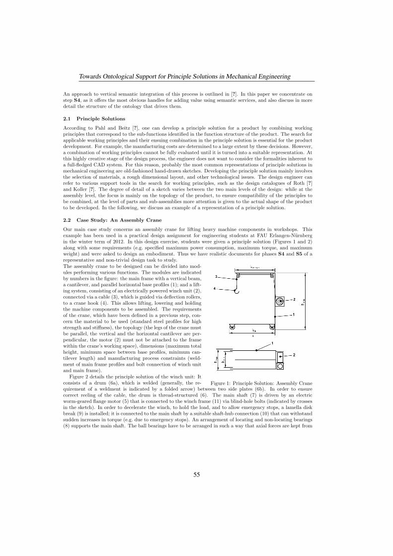
An approach to vertical semantic integration of this process is outlined in [?]. In this paper we concentrate onstep S4, as it offers the most obvious handles for adding value using semantic services, and also discuss in moredetail the structure of the ontology that drives them.
2.1 Principle Solutions
According to Pahl and Beitz [?], one can develop a principle solution for a product by combining workingprinciples that correspond to the sub-functions identified in the function structure of the product. The search forapplicable working principles and their ensuing combination in the principle solution is essential for the productdevelopment. For example, the manufacturing costs are determined to a large extent by these decisions. However,a combination of working principles cannot be fully evaluated until it is turned into a suitable representation. Atthis highly creative stage of the design process, the engineer does not want to consider the formalities inherent toa full-fledged CAD system. For this reason, probably the most common representations of principle solutions inmechanical engineering are old-fashioned hand-drawn sketches. Developing the principle solution mainly involvesthe selection of materials, a rough dimensional layout, and other technological issues. The design engineer canrefer to various support tools in the search for working principles, such as the design catalogues of Roth [?]and Koller [?]. The degree of detail of a sketch varies between the two main levels of the design: while at theassembly level, the focus is mainly on the topology of the product, to ensure compatibility of the principles tobe combined, at the level of parts and sub-assemblies more attention is given to the actual shape of the productto be developed. In the following, we discuss an example of a representation of a principle solution.
2.2 Case Study: An Assembly Crane
Our main case study concerns an assembly crane for lifting heavy machine components in workshops. Thisexample has been used in a practical design assignment for engineering students at FAU Erlangen-Nurnbergin the winter term of 2012. In this design exercise, students were given a principle solution (Figures 1 and 2)along with some requirements (e.g. specified maximum power consumption, maximum torque, and maximumweight) and were asked to design an embodiment. Thus we have realistic documents for phases S4 and S5 of arepresentative and non-trivial design task to study.
Figure 1: Principle Solution: Assembly Crane
The assembly crane to be designed can be divided into mod-ules performing various functions. The modules are indicatedby numbers in the figure: the main frame with a vertical beam,a cantilever, and parallel horizontal base profiles (1); and a lift-ing system, consisting of an electrically powered winch unit (2),connected via a cable (3), which is guided via deflection rollers,to a crane hook (4). This allows lifting, lowering and holdingthe machine components to be assembled. The requirementsof the crane, which have been defined in a previous step, con-cern the material to be used (standard steel profiles for highstrength and stiffness), the topology (the legs of the crane mustbe parallel, the vertical and the horizontal cantilever are per-pendicular, the motor (2) must not be attached to the framewithin the crane’s working space), dimensions (maximum totalheight, minimum space between base profiles, minimum can-tilever length) and manufacturing process constraints (weld-ment of main frame profiles and bolt connection of winch unitand main frame).
Figure 2 details the principle solution of the winch unit: Itconsists of a drum (6a), which is welded (generally, the re-quirement of a weldment is indicated by a folded arrow) between two side plates (6b). In order to ensurecorrect reeling of the cable, the drum is thread-structured (6). The main shaft (7) is driven by an electricworm-geared flange motor (5) that is connected to the winch frame (11) via blind-hole bolts (indicated by crossesin the sketch). In order to decelerate the winch, to hold the load, and to allow emergency stops, a lamella diskbreak (9) is installed; it is connected to the main shaft by a suitable shaft-hub connection (10) that can withstandsudden increases in torque (e.g. due to emergency stops). An arrangement of locating and non-locating bearings(8) supports the main shaft. The ball bearings have to be arranged in such a way that axial forces are kept from
Towards Ontological Support for Principle Solutions in Mechanical Engineering
55
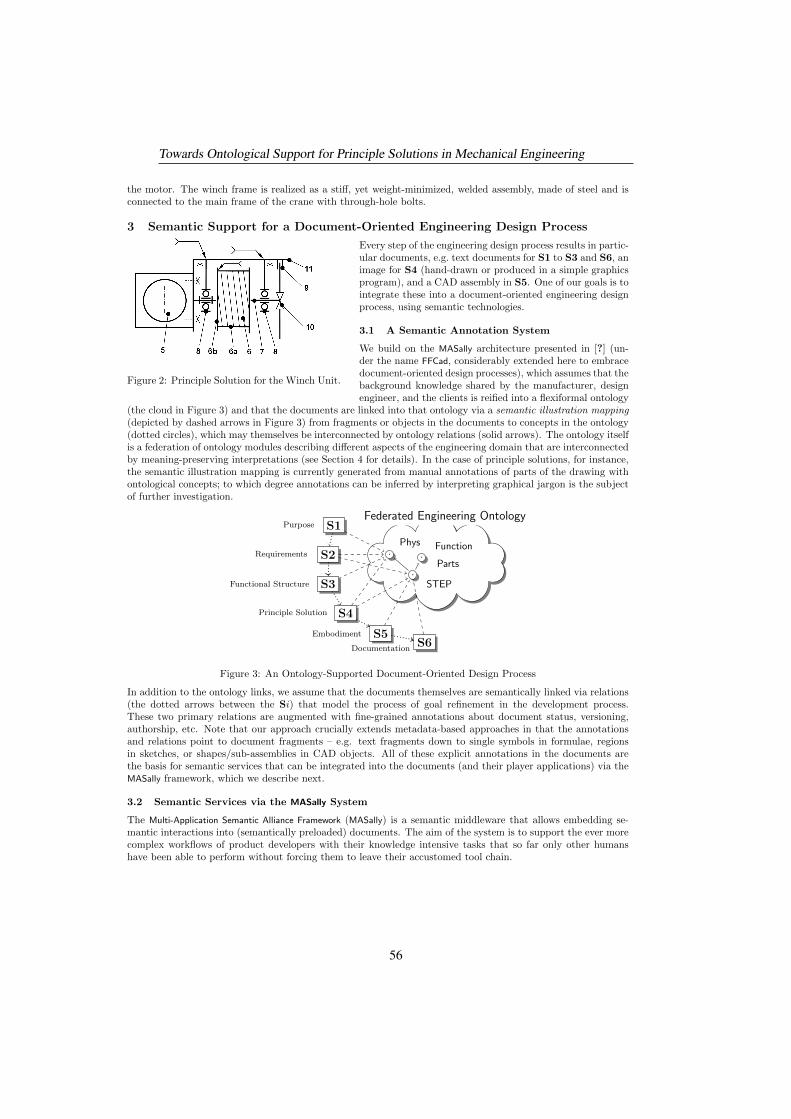
the motor. The winch frame is realized as a stiff, yet weight-minimized, welded assembly, made of steel and isconnected to the main frame of the crane with through-hole bolts.
3 Semantic Support for a Document-Oriented Engineering Design Process
Figure 2: Principle Solution for the Winch Unit.
Every step of the engineering design process results in partic-ular documents, e.g. text documents for S1 to S3 and S6, animage for S4 (hand-drawn or produced in a simple graphicsprogram), and a CAD assembly in S5. One of our goals is tointegrate these into a document-oriented engineering designprocess, using semantic technologies.
3.1 A Semantic Annotation System
We build on the MASally architecture presented in [?] (un-der the name FFCad, considerably extended here to embracedocument-oriented design processes), which assumes that thebackground knowledge shared by the manufacturer, designengineer, and the clients is reified into a flexiformal ontology
(the cloud in Figure 3) and that the documents are linked into that ontology via a semantic illustration mapping(depicted by dashed arrows in Figure 3) from fragments or objects in the documents to concepts in the ontology(dotted circles), which may themselves be interconnected by ontology relations (solid arrows). The ontology itselfis a federation of ontology modules describing different aspects of the engineering domain that are interconnectedby meaning-preserving interpretations (see Section 4 for details). In the case of principle solutions, for instance,the semantic illustration mapping is currently generated from manual annotations of parts of the drawing withontological concepts; to which degree annotations can be inferred by interpreting graphical jargon is the subjectof further investigation.
Purpose S1
Requirements S2
Functional Structure S3
Principle Solution S4
Embodiment S5Documentation
S6
·
··
STEP
Function
Parts
Phys
Federated Engineering Ontology
Figure 3: An Ontology-Supported Document-Oriented Design Process
In addition to the ontology links, we assume that the documents themselves are semantically linked via relations(the dotted arrows between the Si) that model the process of goal refinement in the development process.These two primary relations are augmented with fine-grained annotations about document status, versioning,authorship, etc. Note that our approach crucially extends metadata-based approaches in that the annotationsand relations point to document fragments – e.g. text fragments down to single symbols in formulae, regionsin sketches, or shapes/sub-assemblies in CAD objects. All of these explicit annotations in the documents arethe basis for semantic services that can be integrated into the documents (and their player applications) via theMASally framework, which we describe next.
3.2 Semantic Services via the MASally System
The Multi-Application Semantic Alliance Framework (MASally) is a semantic middleware that allows embedding se-mantic interactions into (semantically preloaded) documents. The aim of the system is to support the ever morecomplex workflows of product developers with their knowledge intensive tasks that so far only other humanshave been able to perform without forcing them to leave their accustomed tool chain.
Towards Ontological Support for Principle Solutions in Mechanical Engineering
56
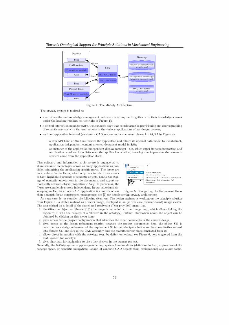
3D model + semlinks
CAD system
Alex
Theo
Text Model + semlinks
Project Docs
Alex
Theo
Desktop
abs. CAD model
abs. text model
Sally
Comet
Comet
Comet
Comet
Project documentation– semiformal –
Background knowledge(physics, engineering)
ISO/DIN norms– semiformal –
...
Planetary
REST
Figure 4: The MASally Architecture
The MASally system is realized as
• a set of semiformal knowledge management web services (comprised together with their knowledge sourcesunder the heading Planetary on the right of Figure 4);
• a central interaction manager (Sally, the semantic ally) that coordinates the provisioning and choreographingof semantic services with the user actions in the various applications of her design process;
• and per application involved (we show a CAD system and a document viewer for S4/S5 in Figure 4)
– a thin API handler Alex that invades the application and relates its internal data model to the abstract,application-independent, content-oriented document model in Sally;
– an instance of the application-independent display manager Theo, which super-imposes interaction andnotification windows from Sally over the application window, creating the impression the semanticservices come from the application itself.
Figure 5: Navigating the Refinement Rela-tion
This software and information architecture is engineered toshare semantic technologies across as many applications as pos-sible, minimizing the application-specific parts. The latter areencapsulated in the Alexes, which only have to relate user eventsto Sally, highlight fragments of semantic objects, handle the stor-age of semantic annotations in the documents, and export se-mantically relevant object properties to Sally. In particular, theTheos are completely system-independent. In our experience de-veloping an Alex for an open-API application is a matter of lessthan a month for an experienced programmer; see [?] for details on the MASally architecture.
As a use case, let us consider the following situation. The design engineer is working on the principle solutionfrom Figure 1 – a sketch realized as a vector image, displayed in an (in this case browser-based) image viewer.The user clicked on a detail of the sketch and received a (Theo-provided) menu that
1. identifies the object as ‘Sheave S13’ (the image is extended with an image map, which allows linking theregion ‘S13’ with the concept of a ‘sheave’ in the ontology); further information about the object can beobtained by clicking on this menu item;
2. gives access to the project configuration that identifies the other documents in the current design;3. gives access to the design refinement relation between the project documents: here, the object S13 is
construed as a design refinement of the requirement S3 in the principle solution and has been further refinedinto objects S17 and S19 in the CAD assembly and the manufacturing plans generated from it;
4. allows direct interaction with the ontology (e.g. by definition lookup; see Figure 6, here triggered from theCAD system for variety);
5. gives shortcuts for navigation to the other sheaves in the current project.Generally, the MASally system supports generic help system functionalities (definition lookup, exploration of theconcept space, or semantic navigation: lookup of concrete CAD objects from explanations) and allows focus-
Towards Ontological Support for Principle Solutions in Mechanical Engineering
57
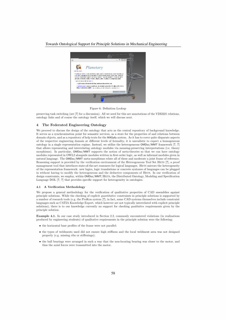
Figure 6: Definition Lookup
preserving task switching (see [?] for a discussion). All we need for this are annotations of the VDI2221 relations,ontology links and of course the ontology itself, which we will discuss next.
4 The Federated Engineering Ontology
We proceed to discuss the design of the ontology that acts as the central repository of background knowledge.It serves as a synchronization point for semantic services, as a store for the properties of and relations betweendomain objects, and as a repository of help texts for the MASally system. As it has to cover quite disparate aspectsof the respective engineering domain at different levels of formality, it is unrealistic to expect a homogeneousontology in a single representation regime. Instead, we utilize the heterogeneous OMDoc/MMT framework [?, ?]that allows representing and interrelating ontology modules via meaning-preserving interpretations (i.e. theorymorphisms). In particular, OMDoc/MMT supports the notion of meta-theories so that we can have ontologymodules represented in OWL2 alongside modules written in first-order logic, as well as informal modules given innatural language. The OMDoc/MMT meta-morphisms relate all of these and moderate a joint frame of reference.Reasoning support is provided by the verification environment of the Heterogeneous Tool Set Hets [?], a proofmanagement tool that interfaces state-of-the-art reasoners for logical languages. Hets mirrors the heterogeneityof the representation framework: new logics, logic translations or concrete syntaxes of languages can be pluggedin without having to modify the heterogeneous and the deductive components of Hets. In our verification ofdesign constraints, we employ, within OMDoc/MMT/Hets, the Distributed Ontology, Modeling and SpecificationLanguage DOL [?, ?] that provides specific support for heterogeneity in ontologies.
4.1 A Verification Methodology
We propose a general methodology for the verification of qualitative properties of CAD assemblies againstprinciple solutions. While the checking of explicit quantitative constraints in principle solutions is supported bya number of research tools (e.g. the ProKon system [?]; in fact, some CAD systems themselves include constraintlanguages such as CATIA Knowledge Expert, which however are not typically interrelated with explicit principlesolutions), there is to our knowledge currently no support for checking qualitative requirements given by theprinciple solution.
Example 4.1. In our case study introduced in Section 2.2, commonly encountered violations (in realizationsproduced by engineering students) of qualitative requirements in the principle solution were the following:
• the horizontal base profiles of the frame were not parallel;
• the types of weldments used did not ensure high stiffness and the local weldment area was not designedproperly (e.g. missing ribs or stiffenings);
• the ball bearings were arranged in such a way that the non-locating bearing was closer to the motor, andthus the axial forces were transmitted into the motor.
Towards Ontological Support for Principle Solutions in Mechanical Engineering
58
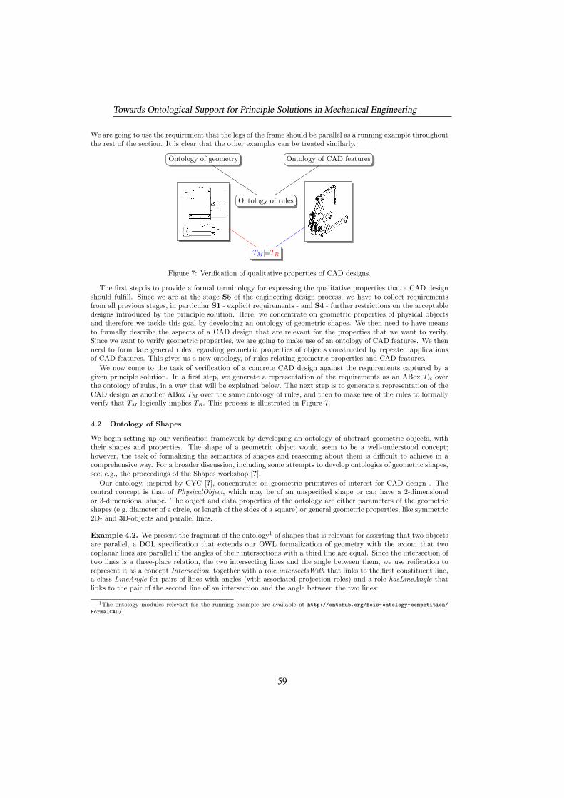
We are going to use the requirement that the legs of the frame should be parallel as a running example throughoutthe rest of the section. It is clear that the other examples can be treated similarly.
Ontology of geometry Ontology of CAD features
Ontology of rules
TM |=TR
Figure 7: Verification of qualitative properties of CAD designs.
The first step is to provide a formal terminology for expressing the qualitative properties that a CAD designshould fulfill. Since we are at the stage S5 of the engineering design process, we have to collect requirementsfrom all previous stages, in particular S1 - explicit requirements - and S4 - further restrictions on the acceptabledesigns introduced by the principle solution. Here, we concentrate on geometric properties of physical objectsand therefore we tackle this goal by developing an ontology of geometric shapes. We then need to have meansto formally describe the aspects of a CAD design that are relevant for the properties that we want to verify.Since we want to verify geometric properties, we are going to make use of an ontology of CAD features. We thenneed to formulate general rules regarding geometric properties of objects constructed by repeated applicationsof CAD features. This gives us a new ontology, of rules relating geometric properties and CAD features.
We now come to the task of verification of a concrete CAD design against the requirements captured by agiven principle solution. In a first step, we generate a representation of the requirements as an ABox TR overthe ontology of rules, in a way that will be explained below. The next step is to generate a representation of theCAD design as another ABox TM over the same ontology of rules, and then to make use of the rules to formallyverify that TM logically implies TR. This process is illustrated in Figure 7.
4.2 Ontology of Shapes
We begin setting up our verification framework by developing an ontology of abstract geometric objects, withtheir shapes and properties. The shape of a geometric object would seem to be a well-understood concept;however, the task of formalizing the semantics of shapes and reasoning about them is difficult to achieve in acomprehensive way. For a broader discussion, including some attempts to develop ontologies of geometric shapes,see, e.g., the proceedings of the Shapes workshop [?].
Our ontology, inspired by CYC [?], concentrates on geometric primitives of interest for CAD design . Thecentral concept is that of PhysicalObject, which may be of an unspecified shape or can have a 2-dimensionalor 3-dimensional shape. The object and data properties of the ontology are either parameters of the geometricshapes (e.g. diameter of a circle, or length of the sides of a square) or general geometric properties, like symmetric2D- and 3D-objects and parallel lines.
Example 4.2. We present the fragment of the ontology1 of shapes that is relevant for asserting that two objectsare parallel, a DOL specification that extends our OWL formalization of geometry with the axiom that twocoplanar lines are parallel if the angles of their intersections with a third line are equal. Since the intersection oftwo lines is a three-place relation, the two intersecting lines and the angle between them, we use reification torepresent it as a concept Intersection, together with a role intersectsWith that links to the first constituent line,a class LineAngle for pairs of lines with angles (with associated projection roles) and a role hasLineAngle thatlinks to the pair of the second line of an intersection and the angle between the two lines:
1The ontology modules relevant for the running example are available at http://ontohub.org/fois-ontology-competition/
FormalCAD/.
Towards Ontological Support for Principle Solutions in Mechanical Engineering
59
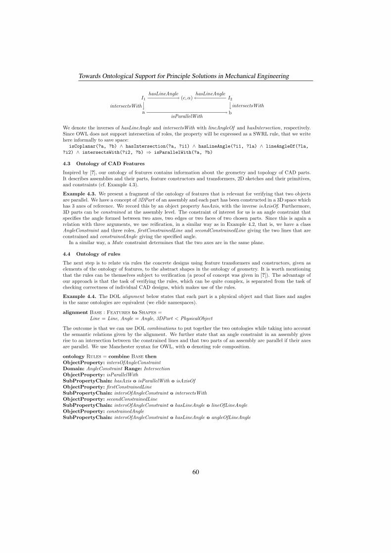
a b
I1 I2(c, α)
isParallelWith
intersectsWith intersectsWith
hasLineAngle hasLineAngle
We denote the inverses of hasLineAngle and intersectsWith with lineAngleOf and hasIntersection, respectively.Since OWL does not support intersection of roles, the property will be expressed as a SWRL rule, that we writehere informally to save space:
isCoplanar(?a, ?b) ∧ hasIntersection(?a, ?i1) ∧ hasLineAngle(?i1, ?la) ∧ lineAngleOf(?la,
?i2) ∧ intersectsWith(?i2, ?b) ⇒ isParallelWith(?a, ?b)
4.3 Ontology of CAD Features
Inspired by [?], our ontology of features contains information about the geometry and topology of CAD parts.It describes assemblies and their parts, feature constructors and transformers, 2D sketches and their primitives,and constraints (cf. Example 4.3).
Example 4.3. We present a fragment of the ontology of features that is relevant for verifying that two objectsare parallel. We have a concept of 3DPart of an assembly and each part has been constructed in a 3D space whichhas 3 axes of reference. We record this by an object property hasAxis, with the inverse isAxisOf. Furthermore,3D parts can be constrained at the assembly level. The constraint of interest for us is an angle constraint thatspecifies the angle formed between two axes, two edges or two faces of two chosen parts. Since this is again arelation with three arguments, we use reification, in a similar way as in Example 4.2, that is, we have a classAngleConstraint and three roles, firstConstrainedLine and secondConstrainedLine giving the two lines that areconstrained and constrainedAngle giving the specified angle.
In a similar way, a Mate constraint determines that the two axes are in the same plane.
4.4 Ontology of rules
The next step is to relate via rules the concrete designs using feature transformers and constructors, given aselements of the ontology of features, to the abstract shapes in the ontology of geometry. It is worth mentioningthat the rules can be themselves subject to verification (a proof of concept was given in [?]). The advantage ofour approach is that the task of verifying the rules, which can be quite complex, is separated from the task ofchecking correctness of individual CAD designs, which makes use of the rules.
Example 4.4. The DOL alignment below states that each part is a physical object and that lines and anglesin the same ontologies are equivalent (we elide namespaces).
alignment Base : Features to Shapes =Line = Line, Angle = Angle, 3DPart < PhysicalObject
The outcome is that we can use DOL combinations to put together the two ontologies while taking into accountthe semantic relations given by the alignment. We further state that an angle constraint in an assembly givesrise to an intersection between the constrained lines and that two parts of an assembly are parallel if their axesare parallel. We use Manchester syntax for OWL, with o denoting role composition.
ontology Rules = combine Base thenObjectProperty: intersOfAngleConstraintDomain: AngleConstraint Range: IntersectionObjectProperty: isParallelWithSubPropertyChain: hasAxis o isParallelWith o isAxisOfObjectProperty: firstConstrainedLineSubPropertyChain: intersOfAngleConstraint o intersectsWithObjectProperty: secondConstrainedLineSubPropertyChain: intersOfAngleConstraint o hasLineAngle o lineOfLineAngleObjectProperty: constrainedAngleSubPropertyChain: intersOfAngleConstraint o hasLineAngle o angleOfLineAngle
Towards Ontological Support for Principle Solutions in Mechanical Engineering
60
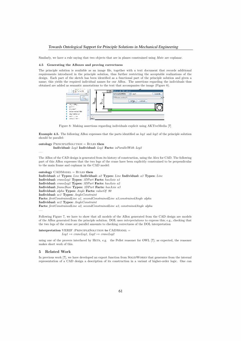
Similarly, we have a rule saying that two objects that are in planes constrained using Mate are coplanar.
4.5 Generating the ABoxes and proving correctness
The principle solution is available as an image file, together with a text document that records additionalrequirements introduced in the principle solution, thus further restricting the acceptable realizations of thedesign. Each part of the sketch has been identified as a functional part of the principle solution and given aname; this yields the required individual names for our ABox. The assertions regarding the individuals thusobtained are added as semantic annotations to the text that accompanies the image (Figure 8).
Figure 8: Making assertions regarding individuals explicit using AKTiveMedia [?]
Example 4.5. The following ABox expresses that the parts identified as leg1 and leg2 of the principle solutionshould be parallel:
ontology PrincipleSolution = Rules thenIndividual: Leg2 Individual: Leg1 Facts: isParallelWith Leg2
. . .
The ABox of the CAD design is generated from its history of construction, using the Alex for CAD. The followingpart of this ABox expresses that the two legs of the crane have been explicitly constrained to be perpendicularto the main frame and coplanar in the CAD model:
ontology CADModel = Rules thenIndividual: a1 Types: Line Individual: a2 Types: Line Individual: a3 Types: LineIndividual: craneLeg1 Types: 3DPart Facts: hasAxis a1Individual: craneLeg2 Types: 3DPart Facts: hasAxis a2Individual: frameBase Types: 3DPart Facts: hasAxis a3Individual: alpha Types: Angle Facts: valueOf 90Individual: ac1 Types: AngleConstraintFacts: firstConstrainedLine a1, secondConstrainedLine a3,constrainedAngle alphaIndividual: ac2 Types: AngleConstraintFacts: firstConstrainedLine a2, secondConstrainedLine a3, constrainedAngle alpha. . .
Following Figure 7, we have to show that all models of the ABox generated from the CAD design are modelsof the ABox generated from the principle solution. DOL uses interpretations to express this; e.g., checking thatthe two legs of the crane are parallel amounts to checking correctness of the DOL interpretation
interpretation VERIF :PrincipleSolution to CADModel =Leg1 7→ craneLeg1, Leg2 7→ craneLeg2
using one of the provers interfaced by Hets, e.g. the Pellet reasoner for OWL [?]; as expected, the reasonermakes short work of this.
5 Related Work
In previous work [?], we have developed an export function from SolidWorks that generates from the internalrepresentation of a CAD design a description of its construction in a variant of higher-order logic. One can
Towards Ontological Support for Principle Solutions in Mechanical Engineering
61
then relate this construction to abstract geometric shapes and prove this relation to be correct using a higher-order proof assistant. In the context of the methodology introduced in Section 4.1, each such relation betweenthe construction and its abstract geometric counterpart gives rise to a formally verified rule in the ontology.At the informal level, we have moreover developed a semantic help system for CAD objects based on theSemantic Alliance Framework [?], and have illustrated the use of this information for semantically supportedtask switching [?]. Our methods should be seen as distinct from the use of ontologies in workflow managementand web service composition, as, e.g., in the Taverna system [?], in that we aim to semanticize the actual contentof documents.
Several ontologies of features have been developed, with the typical application scenario being interoperabilityand data interchange between CAD systems, rather than verification of qualitative properties of CAD assemblies.E.g., OntoSTEP [?] enriches the semantics of CAD objects represented in the system-independent ISO-standardinterchange format STEP. Our heterogeneous approach allows integrating OntoSTEP (or any other ontology offeatures) into our federated engineering ontology and relating it to our ontology of features, without having tomodify our verification methodology.
Various approaches have been explored to integrate semantics into the engineering design process. E.g.,features as used in feature technology [?] aggregate geometric objects and semantics. Different types of featuresare defined (eg. form features, semantic features, application features, compound features), depending stronglyon the technical domain and the product life-cycle phase in which features are used. We expect features to playa role in further semanticizing step S5 (embodiment, Section 2) in future work.
As mentioned in Section 2.1, the most common representations of principle solutions in mechanical engineeringare probably hand-drawn sketches. One alternative approach is the Contact-and-Channel Model (CCM) [?]. Thebasic idea is that every technical system can be represented as a system of working surface pairs and channel andsupport structures. In our case study, an example of a working surface pair would be the shaft-hub connectionbetween the winch main shaft and the lamella disk break, and the main shaft, where the break torque of thedisk break is channeled to the winch drum in order to stop the cable, would be a channel and support structure.Approaches of this kind, in combination with ontological models of function (e.g. [?]; see also the survey byErden et al. [?]), are candidates for integration with our ontological process model in future extensions coveringthe step from the function structure to the principle solution.
6 Conclusions
We have described a framework for semantic support in engineering design processes, focusing on the stepfrom the principle solution to the embodiment, i.e. the CAD model. We base our framework on a flexiformalbackground ontology that combines informal and semiformal parts serving informational purposes with formalizedqualitative engineering knowledge and formal semantic annotation of principle sketches. The latter serve toseparate contingencies of the sketch from its intended information content, and enable automated verification ofthe CAD model against aspects of the principle solution. We combine this approach with a document-orientedprocess that relies on the background ontology for tracking the identity of parts through the design process andacross different applications, which are accessed in a unified manner within the MASally framework.
As a proof of concept, we have illustrated our approach on the partial verification of a CAD model of anassembly crane against the principle solution, showing in particular that the ability to draw logical inferences isimportant when verifying qualitative constraints. This allowed the system to, e.g., accept two parts as satisfyinga parallelism constraint formulated in the principle solution although the CAD model did not mention such aconstraint, which instead had to be inferred from other constraints in the model.
We currently use OWL as the logical core of our verification framework, representing the requisite backgroundknowledge in a TBox and generating ABoxes from the principle sketch and the CAD model. Our approachis based on heterogeneous principles, through use of the Heterogeneous Tool Set Hets and the DistributedOntology, Modeling and Specification Language DOL [?, ?]. It is thus easily possible to go beyond the expressivityboundaries of OWL where necessary, e.g. by moving some parts of (!) the ontology into first-order logic or, moreconservatively, by using rule-based extensions of OWL such as SWRL [?] — this will increase the complexityof reasoning but the Hets system will localize this effect to those parts of the ontology that actually need thehigher expressive power. Use of SWRL will in particular increase the capabilities of the system w.r.t. arithmeticreasoning.
Towards Ontological Support for Principle Solutions in Mechanical Engineering
62
References
[1] Albert Albers and Christian Zingel. Extending SysML for engineering designers by integration of the contactand channel–approach (CCM) for function-based modeling of technical systems. In Systems EngineeringResearch, CSER 2013, volume 16 of Proc. Comput. Sci., pages 353 – 362. Elsevier, 2013.
[2] Raphael Barbau, Sylvere Krima, Rachuri Sudarsan, Anantha Narayanan, Xenia Fiorentini, Sebti Foufou,and Ram D. Sriram. OntoSTEP: Enriching product model data using ontologies. Computer-Aided Design,44:575–590, 2012.
[3] Stefano Borgo, Massimiliano Carrara, Pawel Garbacz, and Pieter Vermaas. A formal ontological perspectiveon the behaviors and functions of technical artifacts. AI EDAM, 23:3–21, 2009.
[4] Thilo Breitsprecher, Mihai Codescu, Constantin Jucovschi, Michael Kohlhase, Lutz Schroder, and SandroWartzack. Semantic support for engineering design processes. In Int. Design Conf., DESIGN 2014, pages1723–1732. Design Society, 2014.
[5] Gino Brunetti and Stephan Grimm. Feature ontologies for the explicit representation of shape semantics.J. Comput. Appl. Technology, 23:192–202, 2005.
[6] Ajay Chakravarthy, Vitaveska Lanfranchi, and Fabio Ciravegna. Requirements for multimedia documentenrichment. In World Wide Web, WWW 2006, pages 903–904. ACM, 2006.
[7] Catalin David, Constantin Jucovschi, Andrea Kohlhase, and Michael Kohlhase. Semantic Alliance: Aframework for semantic allies. In Johan Jeuring, John A. Campbell, Jacques Carette, Gabriel Dos Reis,Petr Sojka, Makarius Wenzel, and Volker Sorge, editors, Intelligent Computer Mathematics, CICM 2012,volume 7362 of LNAI, pages 49–64. Springer, 2012.
[8] M. Erden, Hitoshi Komoto, Thom van Beek, Valentina D’Amelio, E. Echavarria, and Tetsuo Tomiyama. Areview of function modeling: Approaches and applications. AI EDAM, 22:147–169, 2008.
[9] Ian Horrocks, Peter Patel-Schneider, Sean Bechhofer, and Dmitry Tsarkov. OWL rules: A proposal andprototype implementation. J. Web Sem., 3:23–40, 2005.
[10] Ian Horrocks, Peter F. Patel-Schneider, and Frank van Harmelen. From SHIQ and RDF to OWL: themaking of a web ontology language. J. Web Semantics, 1:7–26, 2003.
[11] Sahib Jan, Angela Schwering, Malumbo Chipofya, and Jia Wang. Qualitative representations of schematizedand distorted street segments in sketch maps. In Spatial Cognition 2014, LNCS. Springer, 2014. To appear.
[12] Andrea Kohlhase, Michael Kohlhase, Constantin Jucovschi, and Alexandru Toader. Full semantic trans-parency: Overcoming boundaries of applications. In Paula Kotze, Gary Marsden, Gitte Lindgaard, JanetWesson, and Marco Winckler, editors, Human-Computer Interaction, INTERACT 2013, volume 8119 ofLNCS, pages 406–423. Springer, 2013.
[13] Michael Kohlhase. OMDoc – An open markup format for mathematical documents [Version 1.2], volume4180 of LNAI. Springer, 2006.
[14] Michael Kohlhase. Knowledge management for systematic engineering design in CAD systems. In FranzLehner, Nadine Amende, and Nora Fteimi, editors, Professionelles Wissenmanagement, ProWM 2013, pages202–217. GITO, 2013.
[15] Michael Kohlhase, Johannes Lemburg, Lutz Schroder, and Ewaryst Schulz. Formal management of CAD/-CAM processes. In Ana Cavalcanti and Dennis Dams, editors, Formal Methods, FM 2009, volume 5850 ofLNCS, pages 223–238. Springer, 2009.
[16] Rudolf Koller and Norbert Kastrup. Prinziplosungen zur Konstruktion technischer Produkte. Springer, 1994.
[17] Martin Kratzer, Michael Rauscher, H Binz, and P Gohner. Konzept eines Wissensintegrationssystemszur benutzerfreundlichen, benutzerspezifischen und selbstandigen Integration von Konstruktionswissen. InDesign for X, DFX 2011. TuTech Innovation, 2011.
Towards Ontological Support for Principle Solutions in Mechanical Engineering
63
[18] Oliver Kutz, Mehul Bhatt, Stefano Borgo, and Paulo Santos, editors. The Shape of Things, SHAPES 2013,volume 1007 of CEUR Workshop Proc., 2013.
[19] D. Lenat. Cyc: A Large-Scale Investment in Knowledge Infrastructure. CACM, 38:33–38, 1995.
[20] Till Mossakowski, Oliver Kutz, Mihai Codescu, and Christoph Lange. The distributed ontology, modelingand specification language. In Modular Ontologies, WoMo 2013, volume 1081 of CEUR Workshop Proc.,2013.
[21] Till Mossakowski, Christoph Lange, and Oliver Kutz. Three semantics for the core of the distributed ontologylanguage (extended abstract). In Francesca Rossi, editor, International Joint Conference on ArtificialIntelligence, IJCAI 2013. IJCAI/AAAI, 2013.
[22] Till Mossakowski, Christian Maeder, and Klaus Luttich. The Heterogeneous Tool Set, Hets. In Tools Alg.Constr. Anal. Systems, TACAS 2007, volume 4424 of LNCS, pages 519–522. Springer, 2007.
[23] G Pahl, W Beitz, J Feldhusen, and K.-H. Grote. Engineering Design. Springer, 3rd edition, 2007.
[24] Florian Rabe and Michael Kohlhase. A scalable module system. Inf. Comput., 230:1–54, 2013.
[25] Karlheinz Roth. Konstruieren mit Konstruktionskatalogen. Springer, 1994.
[26] Evren Sirin, Bijan Parsia, Bernardo Cuenca Grau, Aditya Kalyanpur, and Yarden Katz. Pellet: A practicalOWL-DL reasoner. J. Web Semantics, 5:51–53, 2007.
[27] VDI. Methodik zum Entwickeln und Konstruieren technischer Systeme und Produkte (Systematic approachto the development and design of technical systems and products) – VDI 2221, 1993.
[28] VDI. Informationsverarbeitung in der Produktentwicklung – Feature-Technologie (Information technology inproduct development – Feature Technology) – VDI 2218, 2003.
[29] Katherine Wolstencroft, Robert Haines, Donal Fellows, Alan Williams, David Withers, Stuart Owen, StianSoiland-Reyes, Ian Dunlop, Aleksandra Nenadic, Paul Fisher, Jiten Bhagat, Khalid Belhajjame, Finn Bacall,Alex Hardisty, Abraham Nieva de la Hidalga, Maria Balcazar Vargas, Shoaib Sufi, and Carole Goble. TheTaverna workflow suite: designing and executing workflows of web services on the desktop, web or in thecloud. Nucl. Acids Res., 2013.
Towards Ontological Support for Principle Solutions in Mechanical Engineering
64