Embed Size (px)
Citation preview
FOOT SWITCH 2420
DUST AND WATER PROTECTION IP 65/IP 67
j SPECIAL ACCESSORIES AND FEATURES
Metal protection cover
Switching function
Customized cable
Colors
Special material
Logo
Enables application in heavy dutyenvironments for user- and equipmentprotection
Further switching functions possible
Customer specific cable assembly withconnector
Different rocker colors possible- dyed plástic- painted
Special material for medica! use(desinfectare)
Customer specific logo on the rocker
DRAWINGS AND DIMENSIONS
m.i
total trowl pnltion
BeigelEgte Bedíeraugsmleitung bcorfitariPlww seo diBO user «anual Cor M/twr írfrtiotion
KroPt in Ruhestel lungr<rce in fres position
Krort on ScholtpuríitTorce ot Dpsratí
24- N s ID N
30 N i 10 N
Kroft inEndstBlliftg 35 N i 10 Nfloree ot tabal trove! pesition
mflRQUflRDTMarquardt Mechatronik GmbH • Schloss-Strafie 16 • 78604 Rietheim-Weilheim • Germany
Phone ++49 (0) 74 24 / 99-0 • Telefax ++49 (0) 74 24 / 99-23 99 • m^!3u^[email protected] • www.marquardt.de
oC!
(D
Ero
FOOT SWITCH 2420
DUST AND WATER PROTECTION IP 65/IP 67
BENEFITS / FEATURES
• Applicable for harsh environments -> High dust and water protection IP 65/IP 67
• User-friendly ergonomics -> Robust design and olear tactile feedback. Anti-skid and compact, optionalwith screw hole option for fixation on the ground
• Million-times proven high Ufe endurance -> Reliable snap action switching system
• Wide range of ratings •> Capable from signal currents up to powerful 21 A
• High flexibility -> Numerous switching functions and available with and without cable
• Attractive design -> Modern switch shape and different colors possible
Electrical rating
Europe
America
Available on demand
Switching function andPoles
Further functionalityavailable on demand
Protection type
Mechanical life endurance
Ambient temperature
Termination
Actuating forcé single stepdouble step
Flammability
Approvals(IEC/UL61058)
Signal current - 100,000 cycles
16 (8) A 250 V AC -10.000 cycles16 (4) A 250 V AC - 25.000 cycles
16 A 125-250 VAC 1/2 HP
21(8)A250VAC21 A250VAC2HP
off-on SP, DPoff - on (latching) SP, DPon-on : SP, DPoff - on - on 2 x SPon - on - on 2 x SP
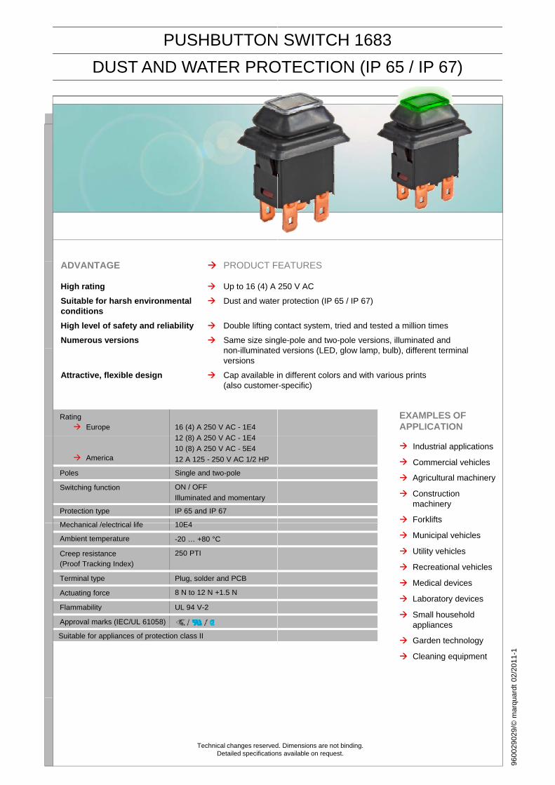
IP 65 and IP 67
> 100.000 cycles
-40... +85 °C
Standard connection clamps, cable harness
30 N ± 10 N1st step 29 N ± 10 N; 2nd step 51 N ± 35 N
UL 94 V-2
ENEC, UL and CSA
Suitable for appliances of protection class II
APPLICATIONS
• Medical equipment
• Laboratory equipment
• Office equipment
• Industry
• Music equipment
• Light equipment
• CCTV
• Material handling
• Conveyor technology
We reserve the right to alter switches ¡n accordance with technical ¡mprovements.Dimensions are not binding. Detailed specifications available on request.
Era
Technical changes reserved. Dimensions are not binding.
Detailed specifications available on request.
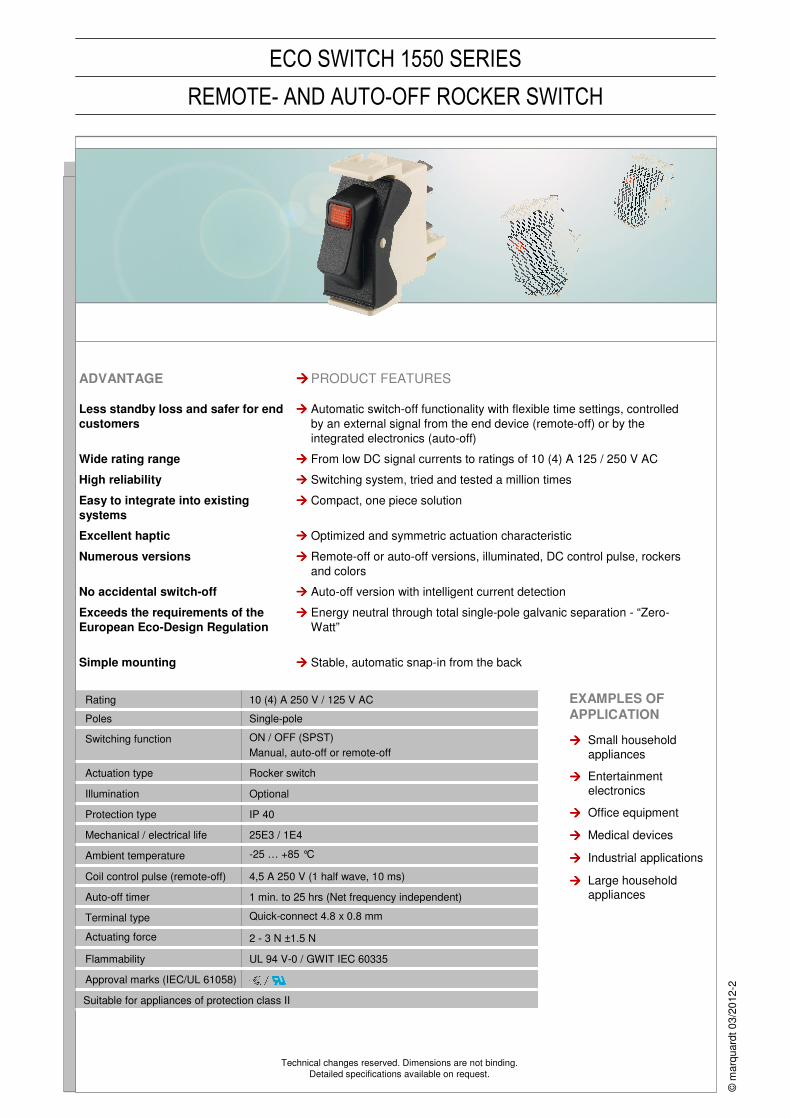
ECO SWITCH 1550 SERIES
REMOTE- AND AUTO-OFF ROCKER SWITCH
IP 40Protection type
Rating 10 (4) A 250 V / 125 V AC
Poles Single-pole
Switching function ON / OFF (SPST)
Manual, auto-off or remote-off
Actuation type Rocker switch
Illumination Optional
Mechanical / electrical life 25E3 / 1E4
Ambient temperature -25 … +85 °C
Coil control pulse (remote-off) 4,5 A 250 V (1 half wave, 10 ms)
Auto-off timer 1 min. to 25 hrs (Net frequency independent)
Terminal type Quick-connect 4.8 x 0.8 mm
Actuating force 2 - 3 N ±1.5 N
Flammability UL 94 V-0 / GWIT IEC 60335
Approval marks (IEC/UL 61058)
Suitable for appliances of protection class II
Energy neutral through total single-pole galvanic separation - “Zero-
Watt”
����Exceeds the requirements of the
European Eco-Design Regulation
Compact, one piece solution����Easy to integrate into existing
systems
ADVANTAGE ����PRODUCT FEATURES
Less standby loss and safer for end
customers
���� Automatic switch-off functionality with flexible time settings, controlled
by an external signal from the end device (remote-off) or by the
integrated electronics (auto-off)
Wide rating range ���� From low DC signal currents to ratings of 10 (4) A 125 / 250 V AC
High reliability ���� Switching system, tried and tested a million times
Excellent haptic ���� Optimized and symmetric actuation characteristic
Numerous versions ���� Remote-off or auto-off versions, illuminated, DC control pulse, rockers
and colors
No accidental switch-off ���� Auto-off version with intelligent current detection
Simple mounting ���� Stable, automatic snap-in from the back
EXAMPLES OF
APPLICATION
���� Small household appliances
���� Entertainment electronics
���� Office equipment
���� Medical devices
���� Industrial applications
���� Large household appliances
©m
arq
uard
t 0
3/2
012-2
Marquardt Mechatronik GmbH · Schloss-Straße 16 · 78604 Rietheim-Weilheim · GermanyTelefon +49 (0) 74 24 / 99-0 · Telefax +49 (0) 74 24 / 99-23 99 · [email protected] · www.marquardt-schalter.de
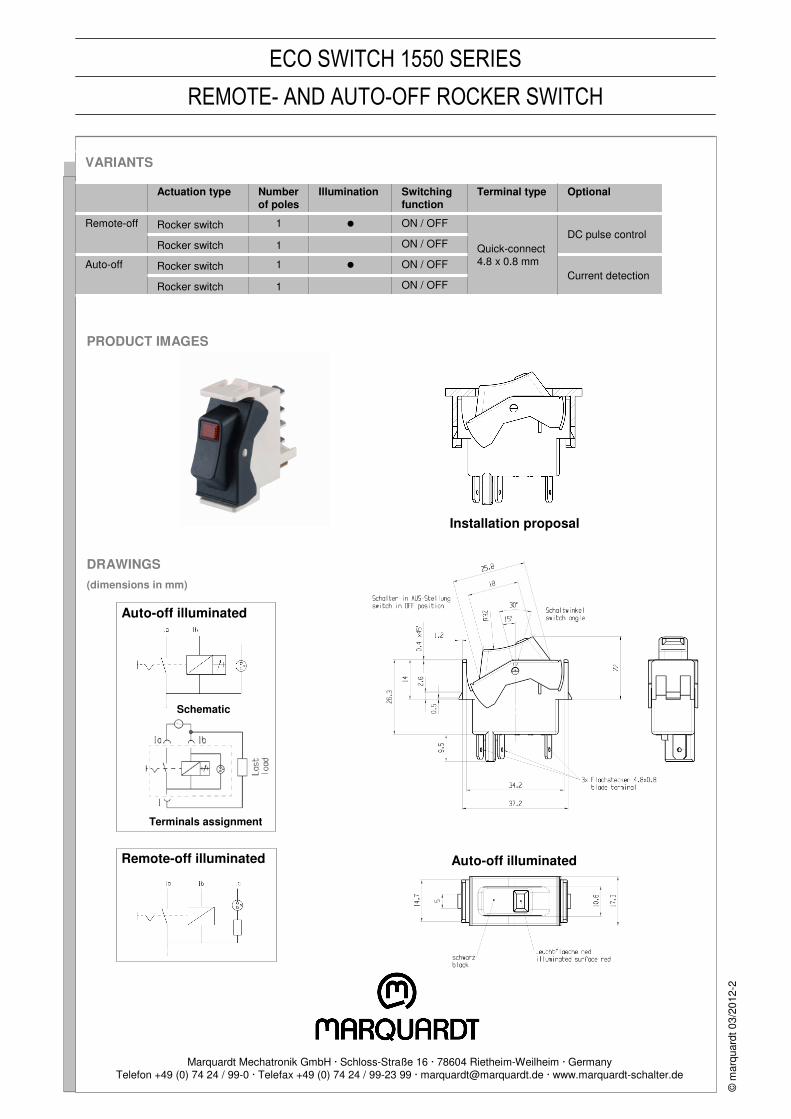
PRODUCT IMAGES
ECO SWITCH 1550 SERIES
REMOTE- AND AUTO-OFF ROCKER SWITCH
DRAWINGS
(dimensions in mm)
©m
arq
uard
t 0
3/2
012-2
Current detection
DC pulse control
Optional
VARIANTS
Actuation type Number of poles
Illumination Switching function
Terminal type
Remote-off Rocker switch 1 � ON / OFF
Quick-connect 4.8 x 0.8 mm
Rocker switch 1 ON / OFF
Auto-off Rocker switch 1 � ON / OFF
Rocker switch 1 ON / OFF
Installation proposal
Auto-off illuminated
Schematic
Terminals assignment
Remote-off illuminated Auto-off illuminated
51 |
SE
NS
OR
SM
ICR
O-S
IGN
AL S
WIT
CH
ES
SN
AP
-AC
TIO
N S
WIT
CH
ES
TA
CT
AN
D K
EY
SW
ITC
HE
SP
OW
ER
TO
OL S
WIT
CH
ES
FO
OT
SW
ITC
HE
SR
OT
AR
Y S
WIT
CH
ES
SL
IDE
SW
ITC
HE
ST
OG
GL
E S
WIT
CH
ES
PU
SH
BU
TT
ON
SW
ITC
HE
SR
OC
KE
R S
WIT
CH
ES
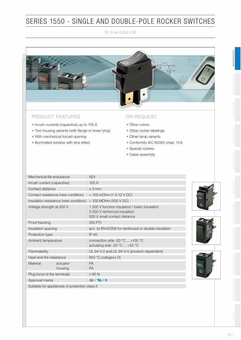
SERIES 1550 - SINGLE AND DOUBLE-POLE ROCKER SWITCHES
TO 16 (4 ) A 250 V AC
Mechanical life endurance 5E4
Inrush current (capacitive) 100 A
Contact distance � 3 mm
Contact resistance (new condition) < 100 mOhm (1 A 12 V DC)
Insulation resistance (new condition) > 100 MOhm (500 V DC)
Voltage strength at 250 V 1 500 V function insulation / basic insulation
3 000 V reinforced insulation
500 V small contact distance
Proof tracking 250 PTI
Insulation spacing acc. to EN 61058 for reinforced or double insulation
Protection type IP 40
Ambient temperature connection side -20 °C ... +100 °C
actuating side -20 °C ... +55 °C
Flammability UL 94 V-2 and UL 94 V-0 (product-dependent)
Heat and fi re resistance 850 °C (category D)
Material actuator
housing
PA
PA
Plug force of the terminals � 80 N
Approval marks � / � / �
Suitable for appliances of protection class II
ON REQUEST
Other colors
Other rocker labelings
Other lamp variants
Conformity IEC 60065 chap. 14.6
Special rockers
Cable assembly
PRODUCT FEATURES
Inrush currents (capacitive) up to 100 A
Two housing variants (with fl ange or lower lying)
With mechanical forced opening
Illuminated window with lens effect
| 52
SERIES 1550 - SINGLE AND DOUBLE-POLE ROCKER SWITCHES
TO 16 (4 ) A 250 V AC
SE
NS
OR
SM
ICR
O-S
IGN
AL S
WIT
CH
ES
SN
AP
-AC
TIO
N S
WIT
CH
ES
TA
CT
AN
D K
EY
SW
ITC
HE
SP
OW
ER
TO
OL S
WIT
CH
ES
FO
OT
SW
ITC
HE
SR
OT
AR
Y S
WIT
CH
ES
SL
IDE
SW
ITC
HE
ST
OG
GL
E S
WIT
CH
ES
PU
SH
BU
TT
ON
SW
ITC
HE
SR
OC
KE
R S
WIT
CH
ES
Volta
ge la
mp
in V
Act
uato
r co
lor
/ pr
intin
g
Hou
sing
col
or
16 (
4) A
25
0 V
AC
5E4
16 (
4) A
25
0 V
AC
1E4
10 (
4) A
25
0 V
AC
5E4
20 m
A 2
50 V
AC
5E4
20 A
25
0 V
AC
2 H
P
20 A
12
5 V
AC
1 H
P
16 A
25
0 V
AC
2 H
P
16 A
12
5 V
AC
1 H
P
Con
nect
ion
type
Con
nect
ion
desc
ript
ion
Con
tact
mat
eria
l
EN
60
33
5 c
ap. 3
0 c
onfo
rm “
G”
Mis
cella
neou
s
Sto
ck v
ersi
on
single-pole
1550.3102 230 6.3 Ag
1550.3105 12 6.3 Ag 12 V 10 A DC
1550.3609 12 6.3 Ag12 V 10 A DC
low lying fl ange
1551.2602 Ag low lying fl ange
1551.3102 6.3 Ag
1551.3103 6.3 Ag
1551.3105 6.3 Ag
1551.3106 6.3 Ag
1551.4803 Ag2 PCB holders
low lying fl ange
1551.2654 Au low lying fl ange
ON/OFF switch (SPST)
1581.1303 6.3 Ag special, robust switching system
1551.1303 6.3 Ag
Normally closed contact (SPNC)
1551.1203 4.8 Ag
1551.3202 6.3 Ag
1551.3702 6.3 Ag low lying fl ange
Normally open contact (SPNO)

53 |
SERIES 1550 - SINGLE AND DOUBLE-POLE ROCKER SWITCHES
TO 16 (4 ) A 250 V AC
SE
NS
OR
SM
ICR
O-S
IGN
AL S
WIT
CH
ES
SN
AP
-AC
TIO
N S
WIT
CH
ES
TA
CT
AN
D K
EY
SW
ITC
HE
SP
OW
ER
TO
OL S
WIT
CH
ES
FO
OT
SW
ITC
HE
SR
OT
AR
Y S
WIT
CH
ES
SL
IDE
SW
ITC
HE
ST
OG
GL
E S
WIT
CH
ES
PU
SH
BU
TT
ON
SW
ITC
HE
SR
OC
KE
R S
WIT
CH
ES
Volta
ge la
mp
in V
Act
uato
r co
lor
/ pr
intin
g
Hou
sing
col
or
16 (
4) A
25
0 V
AC
5E4
16 (
4) A
25
0 V
AC
1E4
10 (
4) A
25
0 V
AC
5E4
20 m
A 2
50 V
AC
5E4
20 A
25
0 V
AC
2 H
P
20 A
12
5 V
AC
1 H
P
16 A
25
0 V
AC
2 H
P
16 A
12
5 V
AC
1 H
P
Con
nect
ion
type
Con
nect
ion
desc
ript
ion
Con
tact
mat
eria
l
EN
60
33
5 c
ap. 3
0 c
onfo
rm “
G”
Mis
cella
neou
s
Sto
ck v
ersi
on
double-pole
1555.0604 230 Ag low lying fl ange
1555.3102 230 6.3 Ag
1555.3104 230 6.3 Ag
1555.3108 230 6.3 Ag
1555.3604 230 6.3 Ag low lying fl ange
1555.4608 230 Ag low lying fl ange
1555.8104 230 6.3 Ag fl ange dimension 31.5 x 17 mm
1555.3125 115 6.3 Ag
1555.4628 115 Ag low lying fl ange
1555.3120 110 6.3 Ag
1555.3109 110 6.3 Ag
1555.3111 12 6.3 Ag 12 V 10 A DC
1552.0103 Ag
1552.0605 Ag low lying fl ange
1552.2601 Ag low lying fl ange
1552.2602 Ag low lying fl ange
1552.3102 6.3 Ag
1552.3104 6.3 Ag
1552.3111 6.3 Ag
1552.3112 6.3 Agconformant with EN 60065
par. 14.6
1552.3117 6.3 Ag
1552.3120 6.3 Ag
1552.3602 6.3 Ag low lying fl ange
1552.4602 Ag low lying fl ange
1552.4604 Ag low lying fl ange
1552.4606 Ag low lying fl ange
1552.4702 Ag2 PCB holders
low lying fl ange
1552.4802 Ag low lying fl ange
ON/OFF switch (SPST)
| 54
SERIES 1550 - SINGLE AND DOUBLE-POLE ROCKER SWITCHES
TO 16 (4 ) A 250 V AC
SE
NS
OR
SM
ICR
O-S
IGN
AL S
WIT
CH
ES
SN
AP
-AC
TIO
N S
WIT
CH
ES
TA
CT
AN
D K
EY
SW
ITC
HE
SP
OW
ER
TO
OL S
WIT
CH
ES
FO
OT
SW
ITC
HE
SR
OT
AR
Y S
WIT
CH
ES
SL
IDE
SW
ITC
HE
ST
OG
GL
E S
WIT
CH
ES
PU
SH
BU
TT
ON
SW
ITC
HE
SR
OC
KE
R S
WIT
CH
ES
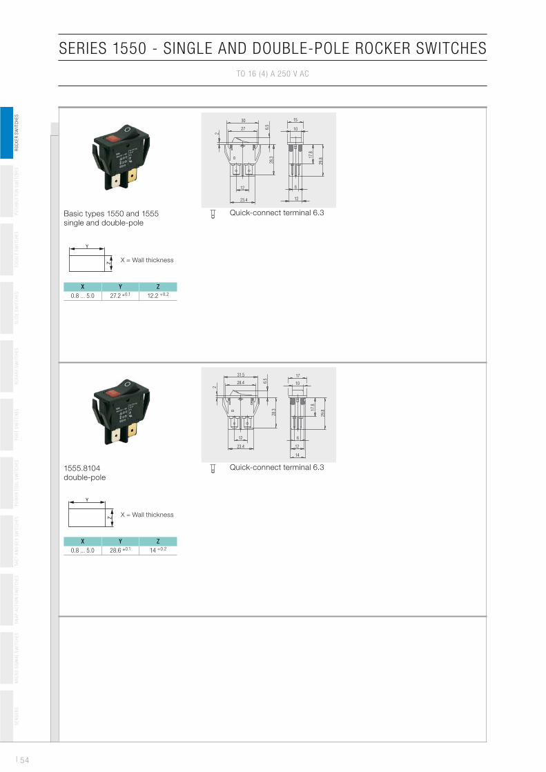
Basic types 1550 and 1555
single and double-pole
X Y Z
0.8 ... 5.0 27.2 �0.1 12.2 +0.2
X = Wall thickness
Quick-connect terminal 6.3
30 15
1027
12
23.4
6
12
28.3 1
7.8
29.8
2
6.5
1555.8104
double-pole
X Y Z
0.8 ... 5.0 28.6 �0.1 14 +0.2
X = Wall thickness
Quick-connect terminal 6.3
10
1731.5
2
6.5
28.3 1
7.8
29.8
28.4
12
23.4
6
12
14
55 |
SERIES 1550 - SINGLE AND DOUBLE-POLE ROCKER SWITCHES
TO 16 (4 ) A 250 V AC
SE
NS
OR
SM
ICR
O-S
IGN
AL S
WIT
CH
ES
SN
AP
-AC
TIO
N S
WIT
CH
ES
TA
CT
AN
D K
EY
SW
ITC
HE
SP
OW
ER
TO
OL S
WIT
CH
ES
FO
OT
SW
ITC
HE
SR
OT
AR
Y S
WIT
CH
ES
SL
IDE
SW
ITC
HE
ST
OG
GL
E S
WIT
CH
ES
PU
SH
BU
TT
ON
SW
ITC
HE
SR
OC
KE
R S
WIT
CH
ES
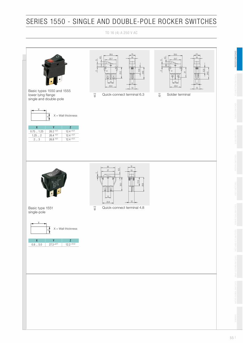
Basic types 1550 and 1555
lower lying flange
single and double-pole
X Y Z
0.75 ... 1.25 26.2 -0.1 12.4 +0.1
1.25 ... 2 26.4 -0.1 12.4 +0.1
2 ... 3 26.8 -0.1 12.4 +0.1
X = Wall thickness
Quick-connect terminal 6.3
29.5
23.7
13
10
6
1223.4
12
52
4.5
23.2 1
2.8
24.8
Solder terminal
29.5
23.7
13
10
12
23.412
6
5
4.5
2
21 1
2.8
24.8
Basic type 1551
single-pole
X Y Z
0.8 ... 5.0 27.3 �0.1 12.2 +0.2
X = Wall thickness
Quick-connect terminal 4.8
30
27
12
23.4 12
10
15
2
6.5
28.3
29.8
17.8
| 56
SERIES 1550 - SINGLE AND DOUBLE-POLE ROCKER SWITCHES
TO 16 (4 ) A 250 V AC
SE
NS
OR
SM
ICR
O-S
IGN
AL S
WIT
CH
ES
SN
AP
-AC
TIO
N S
WIT
CH
ES
TA
CT
AN
D K
EY
SW
ITC
HE
SP
OW
ER
TO
OL S
WIT
CH
ES
FO
OT
SW
ITC
HE
SR
OT
AR
Y S
WIT
CH
ES
SL
IDE
SW
ITC
HE
ST
OG
GL
E S
WIT
CH
ES
PU
SH
BU
TT
ON
SW
ITC
HE
SR
OC
KE
R S
WIT
CH
ES
Basic types 1551 and 1552
single and double-pole
X Y Z
0.8 ... 5.0 27.2 �0.1 12.2 +0.2
X = Wall thickness
Quick-connect terminal 6.3
30 15
1027
12
23.4 12
2
6.5
17
.8
29
.8
28
.3
Solder terminal
30
27
15
10
6
12
12
26
6.5
2
17.8
29.8
23.4
Basic types 1551 and 1552
lower lying flange
single and double-pole
X Y Z
0.75 ... 1.25 26.2 -0.1 12.4 +0.1
1.25 ... 2 26.4 -0.1 12.4 +0.1
2 ... 3 26.8 -0.1 12.4 +0.1
X = Wall thickness
Quick-connect terminal 6.3
29.5
23.7
13
10
6
1223.4
12
12.8
24.8
23.3
5
4.5
2
Solder terminal
29.5
23.7
13
10
6
1223.4
12
5
4.5
2
21 12.8
24.8
PCB terminal angled
29.5
23.7
13
10
6
12.3 3.5
1.3x0.8
12
23.4
5
4.5
2 12.8
17
5
PCB terminal angled
mirror-inverted
29.5
23.7
13
10
6
12.33.5
1.3x0.8
12
23.4
5
4.5
2 17
12.8
5
57 |
SERIES 1550 - SINGLE AND DOUBLE-POLE ROCKER SWITCHES
TO 16 (4 ) A 250 V AC
SE
NS
OR
SM
ICR
O-S
IGN
AL S
WIT
CH
ES
SN
AP
-AC
TIO
N S
WIT
CH
ES
TA
CT
AN
D K
EY
SW
ITC
HE
SP
OW
ER
TO
OL S
WIT
CH
ES
FO
OT
SW
ITC
HE
SR
OT
AR
Y S
WIT
CH
ES
SL
IDE
SW
ITC
HE
ST
OG
GL
E S
WIT
CH
ES
PU
SH
BU
TT
ON
SW
ITC
HE
SR
OC
KE
R S
WIT
CH
ES
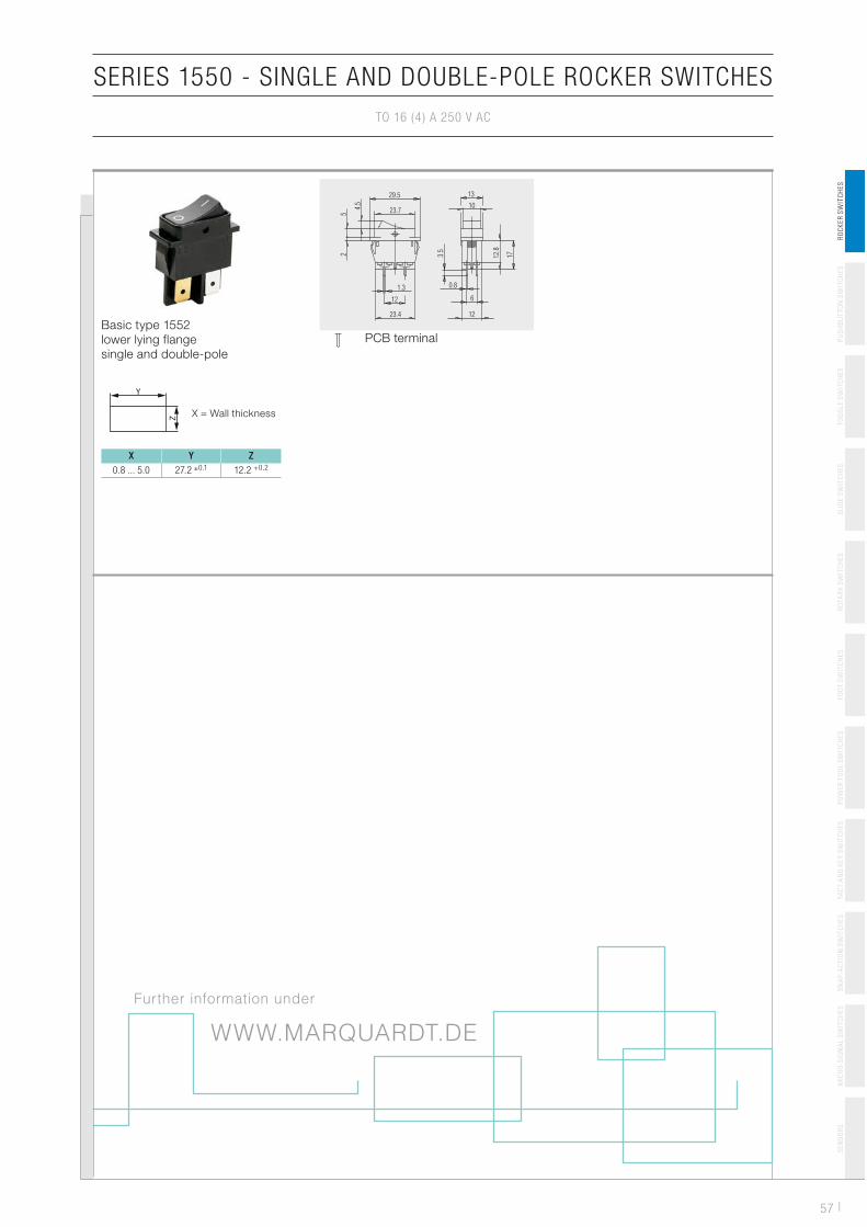
Basic type 1552
lower lying flange
single and double-pole
X Y Z
0.8 ... 5.0 27.2 �0.1 12.2 +0.2
X = Wall thickness
PCB terminal
29.5
23.7
13
10
6
1223.4
12
1.3 0.8
4.5
52 3.5
12.8
17
WWW.MARQUARDT.DE
Further information under
PUSHBUTTON
DUST AND WATER PRO
ADVANTAGE PRODUCT F
High rating Up to 16 (4) A
Suitable for harsh environmental conditions
Dust and water
High level of safety and reliability Double lifting c
Numerous versions Same size singill i t d
Rating Europe 16 (4) A 250 V AC - 1E4
12 (8) A 250 V AC 1E4
non-illuminatedversions
Attractive, flexible design Cap available i(also customer
America
12 (8) A 250 V AC - 1E4
10 (8) A 250 V AC - 5E4
12 A 125 - 250 V AC 1/2 HP
Poles Single and two-pole
Switching function ON / OFF
Illuminated and momentary
Protection type IP 65 and IP 67
M h i l / l t i l lif 10E4Mechanical /electrical life 10E4
Ambient temperature -20 … +80 °C
Creep resistance (Proof Tracking Index)
250 PTI
Terminal type Plug, solder and PCB
Actuating force 8 N to 12 N +1.5 N
Flammability UL 94 V-2y
Approval marks (IEC/UL 61058)
Suitable for appliances of protection class II
Technical changes reservedDetailed specification
SWITCH 1683
OTECTION (IP 65 / IP 67)
EATURES
250 V AC
r protection (IP 65 / IP 67)
contact system, tried and tested a million times
gle-pole and two-pole versions, illuminated and d i (LED l l b lb) diff t t i ld versions (LED, glow lamp, bulb), different terminal
in different colors and with various prints r-specific)
EXAMPLES OF APPLICATION
Industrial applications
Commercial vehicles
Agricultural machinery
Constructionmachinery
Forklifts
Municipal vehicles
Utility vehicles
Recreational vehicles
Medical devices
Laboratory devices
Small householdappliances
Garden technology
Cleaning equipment
ardt
02/
201
1-1
d. Dimensions are not binding. ns available on request.
96
00
29
02
9/©
mar
qu
PUSHBUTTON
DUST AND WATER PRO
VARIANTS
Type Numberof poles
Illumination Switching function Termin
1683 1 ON / OFF (SPST) Quick-ctermina
1683 1 ON / OFFQuick-ctermina
Quick-ctermina(verticahorizon
PCB ter
1683 1 ON / OFF momentary (SPNO)
1684 2 ON / OFF (DPST)
1684 2 ON / OFF momentary (DPNO)
1686 1 ON / OFF (SPST)
1687 2 ON / OFF (DPST)
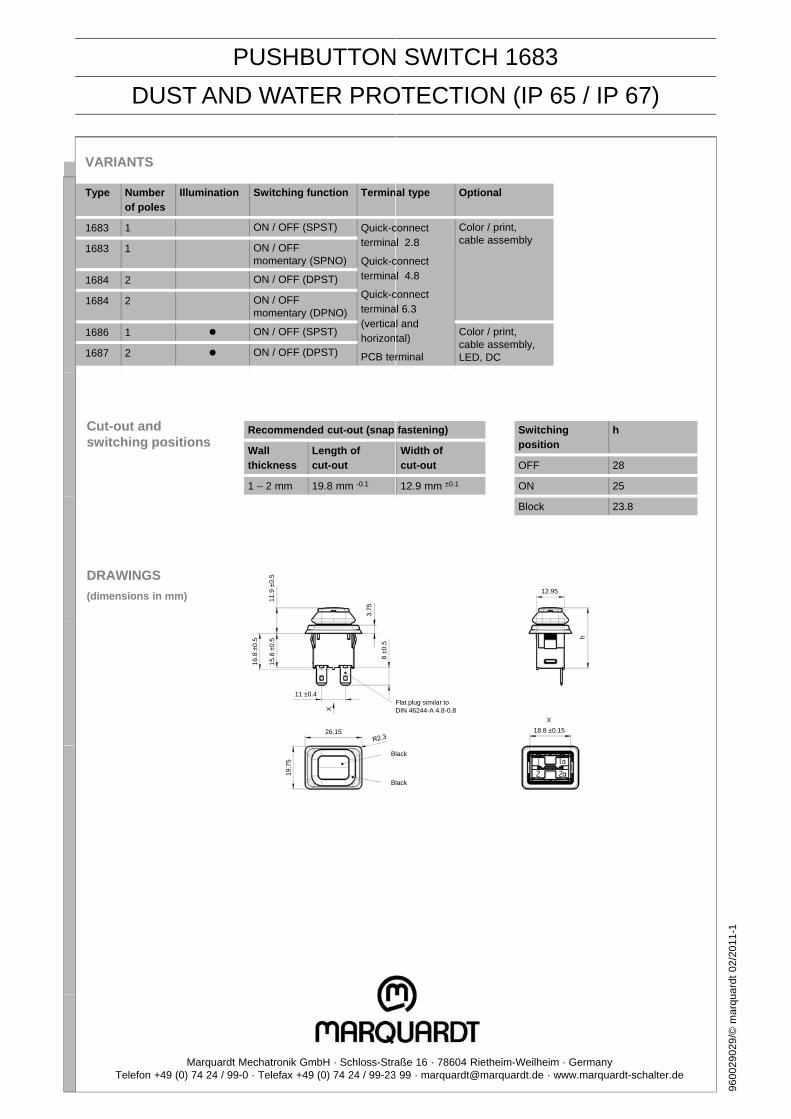
Cut-out andswitching positions
Recommended cut-out (snap
Wall thickness
Length ofcut-out
1 – 2 mm 19.8 mm -0.1
DRAWINGS
(dimensions in mm) 11.9
±0.
5
3.75
11 ±0.4
16.8
±0.
5
15.8
±0.
5
8 ±0
.5
26.15
X
19.7
5
B
B
Marquardt Mechatronik GmbH · Schloss-StraTelefon +49 (0) 74 24 / 99-0 · Telefax +49 (0) 74 24 / 99-23
SWITCH 1683
OTECTION (IP 65 / IP 67)
al type Optional
connectal 2.8
Color / print, cable assembly
connectal 4.8
connect al 6.3 l and tal)
rminal
Color / print, cable assembly, LED, DC
fastening)
Width ofcut-out
12.9 mm ±0.1
Switchingposition
h
OFF 28
ON 25
Block 23.8
12.95
Flat plug similar to DIN 46244-A 4.8-0.8
h
18.8 ±0.15
X
lack
lack
ardt
02/
201
1-1
aße 16 · 78604 Rietheim-Weilheim · Germany 99 · [email protected] · www.marquardt-schalter.de
96
00
29
02
9/©
mar
qu
Technical changes reserved. Dimensions are not binding.
Detailed specifications available on request.
SNAP-ACTION SWITCH 1045
DUST AND WATER PROTECTION (IP 67)
Rating in compliance with
IEC/UL 61058-1
�Europe
�America
10 (3) A 250 V AC 10E3 or 6(6) A 250 V AC 30E3 ENEC
10 (3) A 250 V AC 10E3 or 6(6) A 250 V AC 30E3 UL
Switching function Normally closed, normally open, changeover
Protection type IP 40 and IP 67
Mechanical life 10E6, tightness up to 1.5E6 cycles
Ambient temperature -40 °C … +100 °C
Creep resistance (Proof Tracking Index)
250 PTI
Terminal type Quick-connect terminal 2.8 x 0.5, solder terminal, PCB terminal (straight), PCB terminal (lateral)
Terminal surface Tin-plated, quick-connect terminal 2.8 x 0.5 uncoated
Material
� Housing, actuator
� Terminals
� Additional actuator
PA
Brass
Stainless spring steel / PA
Actuating force 0.7 N … 3.2 N (depending on product)
Difference travel max. 0.2 mm
Overtravel min. 0.5 mm
Contact resistance < 50 mOhm
Bounce time < 5 ms
Flammability UL 94 V-0
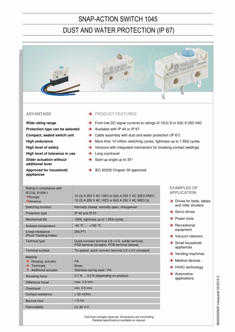
ADVANTAGE ���� PRODUCT FEATURES
Wide rating range ���� From low DC signal currents to ratings of 10(3) A or 6(6) A 250 VAC
Protection type can be selected ���� Available with IP 40 or IP 67
Compact, sealed switch unit ���� Cable assembly with dust and water protection (IP 67)
High endurance ���� More than 10 million switching cycles, tightness up to 1.5E6 cycles
High level of safety ���� Versions with integrated mechanism for breaking contact weldings
High level of tolerance in use ���� Long overtravel
Slider actuation without
additional lever
���� Start-up angle up to 35°
Approved for household
appliances
���� IEC 60335 Chapter 30 approved
EXAMPLES OF
APPLICATION
���� Drives for beds, tables
and roller shutters
���� Servo drives
���� Power tools
���� Recreational
equipment
���� Vacuum cleaners
���� Small household
appliances
���� Vending machines
���� Medical devices
���� HVAC technology
���� Automotive
applications
960
02
20
29/©
marq
uard
t0
2/2
01
2-2
Marquardt Mechatronik GmbH · Schloss-Straße 16 · 78604 Rietheim-Weilheim · GermanyTelefon +49 (0) 74 24 / 99-0 · Telefax +49 (0) 74 24 / 99-23 99 · [email protected] · www.marquardt-schalter.de
SNAP-ACTION SWITCH 1045
DUST AND WATER PROTECTION (IP 67)
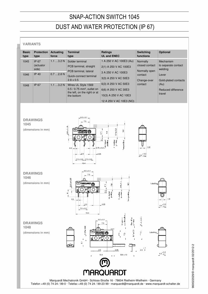
VARIANTS
Basic
type
Protection
type
Actuating
force
Terminal
type
Ratings
UL and ENEC
Switching
functions
Optional
1045 IP 67
(actuator
side)
1.1 …3.2 N Solder terminal
PCB terminal, straight
PCB terminal, lateral
Quick-connect terminal
2.8 x 0.5
1 A 250 V AC 100E3 (Au)
2(1) A 250 V AC 100E3
3 A 250 V AC 100E3
3(3) A 250 V AC 50E3
6(3) A 250 V AC 50E3
6(6) A 250 V AC 30E3
10(3) A 250 V AC 10E3
12 A 250 V AC 10E3 (NO)
Normally
closed contact
Normally open
contact
Change-over
contact
Mechanism
to separate contact
welding
Lever
Gold-plated contacts
(Au)
Reduced difference
travel
1046 IP 40 0.7 …2.8 N
1048 IP 67 1.1 …3.2 N Wires UL Style 1569
0.5 / 0.75 mm², outlet on
the left, on the right or at the bottom
DRAWINGS
1045
(dimensions in mm)
DRAWINGS
1046
(dimensions in mm)
9.5 ± 0.1
7.5
4.95
0.5
2.5
7.5 ± 0.2
19.4
1.8
6.4+ 0.2- 0.1
Labelling
9.5 ± 0.1
7.5
0.5 2.75 ± 0.2
4.952.5
7.5 ± 0.2 7.5 ± 0.2
19.4
1.22
6.4+ 0.2- 0.1
DRAWINGS
1048
(dimensions in mm)
19.4 500 ± 10
9.5 ± 0.1
6.4+ 0.2- 0.1
Labelling
7.5
2.54.952.5+ 1
0
960
02
20
29/©
marq
uard
t0
2/2
01
2-2
8.1
223 |
SE
NS
OR
SS
NA
P-A
CT
ION
SW
ITC
HE
ST
AC
T A
ND
KE
Y S
WIT
CH
ES
PO
WE
R T
OO
L S
WIT
CH
ES
FO
OT
SW
ITC
HE
SR
OT
AR
Y S
WIT
CH
ES
SL
IDE
SW
ITC
HE
ST
OG
GL
E S
WIT
CH
ES
PU
SH
BU
TT
ON
SW
ITC
HE
SM
ICR
O-S
IGN
AL S
WIT
CH
ES
RO
CK
ER
SW
ITC
HE
S
Mechanical life endurance 50E4
Contact resistance (new condition) < 500 mOhm
Insulation resistance (new condition) 1 000 MOhm
Protection type IP 00 connection side basic types 1065 and 1075
IP 67 actuator side all basic types, connection side basic
type 1068
Ambient temperature -40 °C ... +85 °C
Flammability UL 94 V-2
Material actuator
additional actuator
housing
connections
POM
stainless steel spring steel
PBTP
tinned
Contact material Au
Shock resistance 50 g
Miscellaneous terminal side sealed
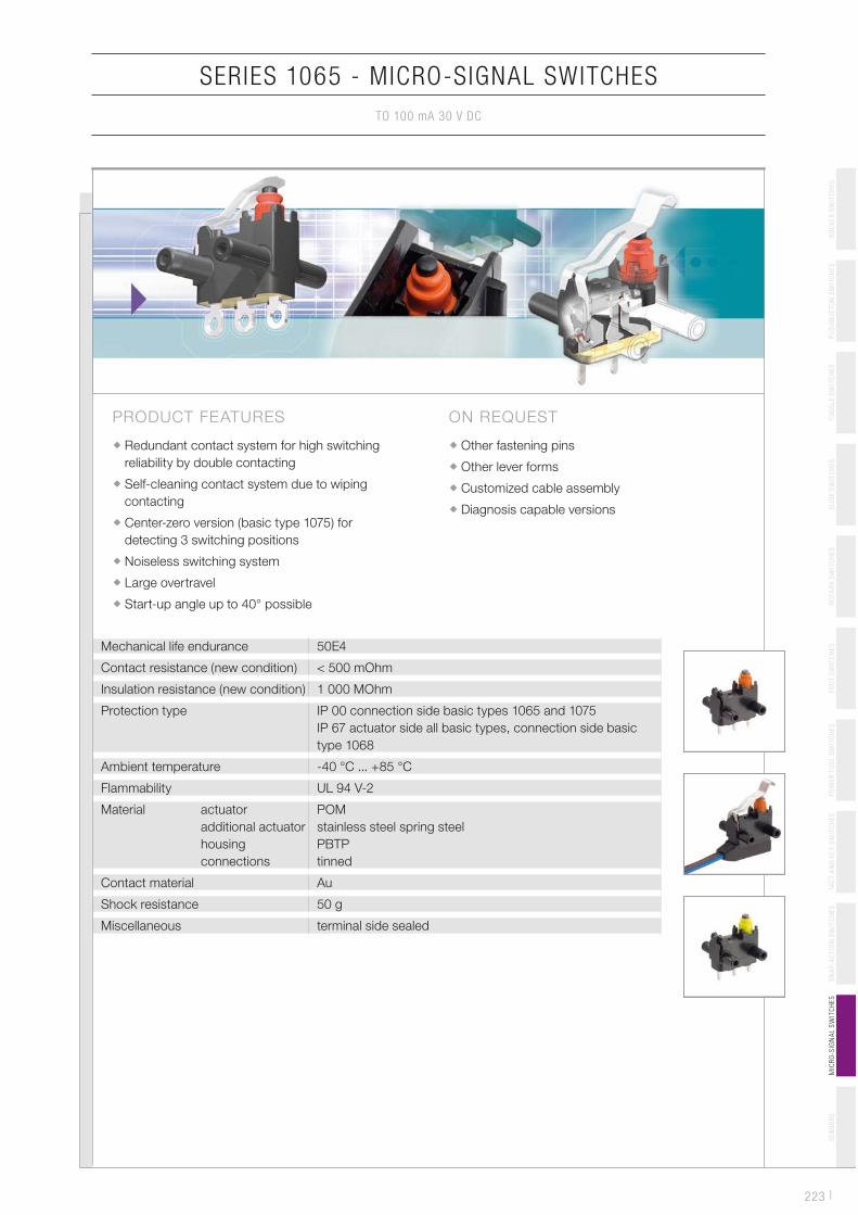
ON REQUEST
Other fastening pins
Other lever forms
Customized cable assembly
Diagnosis capable versions
PRODUCT FEATURES
Redundant contact system for high switching
reliability by double contacting
Self-cleaning contact system due to wiping
contacting
Center-zero version (basic type 1075) for
detecting 3 switching positions
Noiseless switching system
Large overtravel
Start-up angle up to 40° possible
SERIES 1065 - MICRO-SIGNAL SWITCHES
TO 100 mA 30 V DC
| 224
SERIES 1065 - MICRO-SIGNAL SWITCHES
TO 100 mA 30 V DC
SE
NS
OR
SS
NA
P-A
CT
ION
SW
ITC
HE
ST
AC
T A
ND
KE
Y S
WIT
CH
ES
PO
WE
R T
OO
L S
WIT
CH
ES
FO
OT
SW
ITC
HE
SR
OT
AR
Y S
WIT
CH
ES
SL
IDE
SW
ITC
HE
ST
OG
GL
E S
WIT
CH
ES
PU
SH
BU
TT
ON
SW
ITC
HE
SR
OC
KE
R S
WIT
CH
ES
MIC
RO
-SIG
NA
L S
WIT
CH
ES
100 m
A 3
0 V
DC
2E5
10 m
A 1
6 V
DC
50
E4
Con
nect
ion
type
Con
nect
ion
desc
ript
ion
Ope
ratin
g fo
rce
in N
Ope
ratin
g po
sitio
n (O
P N
C) in
mm
OFF
pos
ition
in m
m
Ope
ratin
g po
sitio
n (O
P N
O) in
mm
Free
pos
ition
(FP
) m
ax.
in m
m
Per
mis
sibl
e to
tal t
rave
lpo
sitio
n (T
P) i
n m
m
Act
uato
r de
script
ion
Leve
r dr
awin
g
Mis
cella
neou
s
Sto
ck v
ersi
on
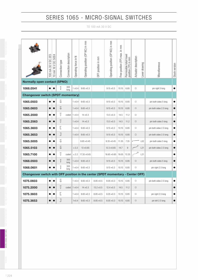
1068.0541300
long1 �0.4 9.65 �0.3 9.15 �0.3 10.15 6.85 pin right 5 long
Normally open contact (SPNO)
1065.0503 1 �0.4 9.65 �0.3 9.15 �0.3 10.15 6.85 pin both sides 5 long
1065.0603 1 �0.4 9.65 �0.3 9.15 �0.3 10.15 6.85 pin both sides 2.5 long
1065.2000 coded 1 �0.4 14 �0.3 13.5 �0.3 14.5 11.2
1065.2563 1 �0.4 14 �0.3 13.5 �0.3 14.5 11.2 pin both sides 5 long
1065.3603 1 �0.4 9.65 �0.3 9.15 �0.3 10.15 6.85 pin both sides 2.5 long
1065.3653 1 �0.4 9.65 �0.3 9.15 �0.3 10.15 6.85 pin both sides 2.5 long
1065.5005 9.85 �0.45 9.35 �0.45 11.35 7.35 L02 pin both sides 5 long
1065.5103 � 2.2 13 �0.65 12.3 �0.65 14.7 9 L21 pin both sides 2.5 long
1065.7100 coded � 2.2 17.35 �0.65 16.65 �0.65 19.05 13.35 L21
1068.0503300
long1 �0.4 9.65 �0.3 9.15 �0.3 10.15 6.85 pin both sides 5 long
1068.0601300
long1 �0.4 9.65 �0.3 9.15 �0.3 10.15 6.85 pin right 2.5 long
Changeover switch (SPDT momentary)
1075.0603 1 �0.4 9.65 �0.3 8.85 �0.5 8.05 �0.3 10.15 6.85 pin both sides 2.5 long
1075.2000 coded 1 �0.4 14 �0.3 13.2 �0.5 12.4 �0.3 14.5 11.2
1075.3603 1 �0.4 9.65 �0.3 8.85 �0.5 8.05 �0.3 10.15 6.85 pin right 2.5 long
1075.3653 1�0.4 9.65 �0.3 8.85 �0.5 8.05 �0.3 10.15 6.85 pin left 2.5 long
Changeover switch with OFF position in the center (SPDT momentary - Center OFF)
225 |
SERIES 1065 - MICRO-SIGNAL SWITCHES
TO 100 mA 30 V DC
SE
NS
OR
SS
NA
P-A
CT
ION
SW
ITC
HE
ST
AC
T A
ND
KE
Y S
WIT
CH
ES
PO
WE
R T
OO
L S
WIT
CH
ES
FO
OT
SW
ITC
HE
SR
OT
AR
Y S
WIT
CH
ES
SL
IDE
SW
ITC
HE
ST
OG
GL
E S
WIT
CH
ES
PU
SH
BU
TT
ON
SW
ITC
HE
SM
ICR
O-S
IGN
AL S
WIT
CH
ES
RO
CK
ER
SW
ITC
HE
S
Basic type 1065 Solder terminal
0.5
ø1.8
55
2.8 ±0.2
ø1.5
3.6
±0.2
PCB terminal
13 ±0.2 ø1.9
1 2 4 5.4 ±0.2
TH: Ø1.3
3.2
3 +
0.0
5 -
0.0
8
�10.1
5
9.6
5±0.3
9.1
5±0.3
6.8
5TP
OP
NO
OP
NC FP
TP
OP
NO
OP
NCFP
11.2
13.5
±0.3
14
±0.3
�14.5
PCB terminal coded and
crowned
3.7
5
5.6
3.8
0.91 2 4
0.5
1.5
TH: Ø1.3
PCB terminal left angled
ø 3.1 -0.08
0.2 x 45°
5 ±0.05
5 ±0.05
ø 3.5
9 ±0.05
3.23 ±0.2
5.6
±0.2
5
0.5
ø 1
.3 +
0.1
ø1.3
-0.0
8
0.2
x 4
5°
5.8
PCB terminal right angled
ø 3.1 -0.08
9 ±0.05
0.2 x 45°
5 ±0.05
5 ±0.05
ø3.5
3.23
0.5 5
.6
5.8
ø 1
.3 +
0.1
ø 3
.1-0
.08
0.2
x 4
5°
Basic type 1068
Cable 300 long, tinned wire
ends
TP 6.85
OP NO 9.15 ±0.3
OP NC 9.65 ±0.35
FP 10.15
ø1.9
5.417
13.7
0.79
4.5
300
3.2
3
7.8
| 226
SERIES 1065 - MICRO-SIGNAL SWITCHES
TO 100 mA 30 V DC
SE
NS
OR
SS
NA
P-A
CT
ION
SW
ITC
HE
ST
AC
T A
ND
KE
Y S
WIT
CH
ES
PO
WE
R T
OO
L S
WIT
CH
ES
FO
OT
SW
ITC
HE
SR
OT
AR
Y S
WIT
CH
ES
SL
IDE
SW
ITC
HE
ST
OG
GL
E S
WIT
CH
ES
PU
SH
BU
TT
ON
SW
ITC
HE
SR
OC
KE
R S
WIT
CH
ES
MIC
RO
-SIG
NA
L S
WIT
CH
ES
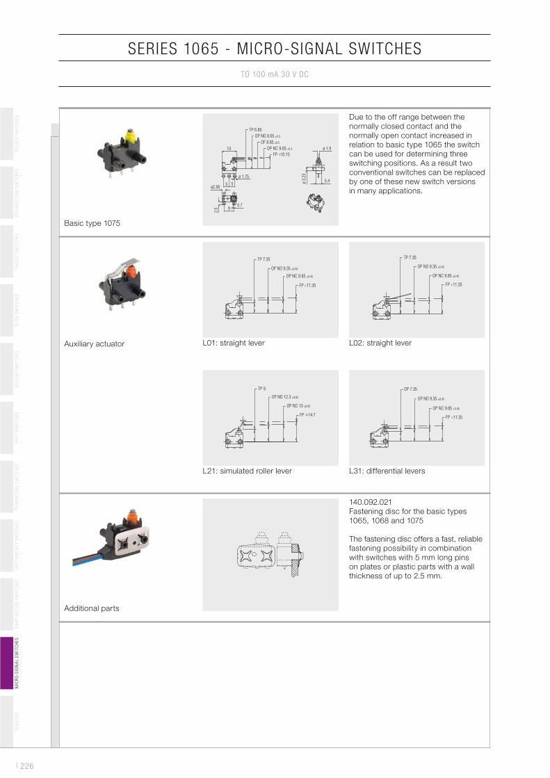
Auxiliary actuator L01: straight lever
TP 7.35
OP NO 9.35 ±0.45
OP NC 9.85 ±0.45
FP 11.35
L02: straight lever
TP 7.35
OP NO 9.35 ±0.45
OP NC 9.85 ±0.45
FP 11.35
L21: simulated roller lever
TP 9
OP NO 12.3 ±0.65
OP NC 13 ±0.65
FP 14.7
L31: differential levers
OP 7.35
OP NO 9.35 ±0.45
OP NC 9.85 ±0.45
FP 11.35
Additional parts
140.092.021
Fastening disc for the basic types
1065, 1068 and 1075
The fastening disc offers a fast, reliable
fastening possibility in combination
with switches with 5 mm long pins
on plates or plastic parts with a wall
thickness of up to 2.5 mm.
Basic type 1075
TP 6.85
OP NO 8.05 ±0.3
OF 8.85 ±0.5
OP NC 9.65 ±0.3
FP 10.15
ø 1.9
5.4ø 1.75
55
13
0.79
2.5
ø 3
.23
ø2.95
Due to the off range between the
normally closed contact and the
normally open contact increased in
relation to basic type 1065 the switch
can be used for determining three
switching positions. As a result two
conventional switches can be replaced
by one of these new switch versions
in many applications.