Embed Size (px)
Citation preview

AL AKHAWAYN UNIVERSITY IN IFRANE
SCHOOL OF SCIENCE AND ENGINEERING
FOOTSTEPS: RENEWED TILES
BY: Fatima Zahra Bouzidy
SUPERVISED BY: Dr. Bouchaib Falah

1
Contents Steeple analysis ............................................................................................................................................. 6
Introduction .................................................................................................................................................. 7
Types of renewable energies .................................................................................................................... 7
Renewable Energies in term of costs ........................................................................................................ 9
Human Locomotion and Energy released ............................................................................................... 10
FootStep ...................................................................................................................................................... 13
Piezoelectric ............................................................................................................................................ 14
The configuration of the tiles .................................................................................................................. 16
Conventional Charge Output Devices ..................................................................................................... 18
Low Impedance Quartz Power Devices .................................................................................................. 21
DTC in ICP Power tiles ............................................................................................................................. 26
Long Duration Events and DTC ............................................................................................................... 31
Calibration of Power Devices .................................................................................................................. 39
Business analysis ......................................................................................................................................... 40
Competitor analysis ................................................................................................................................ 40
Our Suggested design ................................................................................................................................. 41
Recycled aluminum ............................................................................................................................. 42
Piezoelectric systems .......................................................................................................................... 43
Galvanized Steel .................................................................................................................................. 44
Energy Gain and emplacement suggestion ............................................................................................ 45
Monetary gain ......................................................................................................................................... 46
Comparison of both projects outcomes ............................................................................................. 47
Code for energy auditing ............................................................................................................................ 48
Solidworks: floor design .............................................................................................................................. 52
Sketch ...................................................................................................................................................... 52
Technical drawing ................................................................................................................................... 53
Conclusion ................................................................................................................................................... 54
References .................................................................................................................................................. 55

2
List of Tables
Table 1: Cost of Production for the Different Field of Renewable energies
Table 2: Cost for Pavegen
Table 3 : Primer cost estimation of the floor
Table 4: energy collected
Table 5: Electricity billing
Table 6: Summarizing table for the Gains
List of Figures
Figure1: summary of motion energy
Figure2: global view of the system
Figure 3: Tension and compression of impact 208
Figure 4: Schematic of charging mode
Figure 5: charging system
Figure 6: ICP systematic model
Figure 7: system of ICP Device System
Figure 8: ICP Device transfer characteristics
Figure 9: Response step function
Figure 10: Edge loading vs. center loading
Figure 11: Power ring and crystals
Figure 12: Positive Polarity with zero AC output
Figure 13: Aluminum Floor
Figure 14: Piezoelectric sensor
Figure 15: Galvanized Steel

3
Figure 16: Java code
Figure 17: interface trial
Figure18: SolidWorks design

4

5

6
Steeple analysis STEEPLE analysis consists of evaluating the seven factors that makes a project successful for a company,
STEEPLE analysis is composed of Societal, technological, environmental, ethical, political, legal and
economic measures.
Societal
• The population is growing increasingly and the demand for electricity is increasing as well.
Collecting energy from human locomotion will be adaptable to such societal needs.
Technology
• Piezoelectric tiles/floors will help in developing technology inside the country.
Environment
• Piezoelectric tiles have no harm on the environment.
Ethical
• Natural source of collecting energy and do not harm the nature.
Political
• The needs for electricity are growing and they won't be enough for the next generations and
collecting energy from human daily motion ensure present and future human needs for
electricity.
Legal
• Renewed tiles has no harm to human nor to nature, so could it be useful to everybody.
Economical
• Piezoelectric tiles/ floors is saving energy for later usage and in parallel it is making important
savings.

7
Introduction The sun, water, wind, wood and other plant products are all natural resources capable of generating
energy through technics developed by men. Their relative low impact on the environment makes
them energies of the future that help humanity to face the problem of the management of the waste
of the nuclear energy and the emissions of greenhouse gases. Renewable energies also represent
an opportunity for more than two billions isolated people to finally reach electricity. These assets,
together with increasingly efficient technologies, favor the development of renewable energies,
but still very unevenly depending on the type of resources considered. With energy consumption
increasing, it seems unlikely that renewable energy will replace other energy resources in the near
future. It is therefore important that each one of us closely monitors his/her own energy
consumption.
Types of renewable energies
It is an old principle like the windmills. The wind rotates the blades, which are themselves coupled
to a rotor and a generator. When the wind is strong enough (15 km / h minimum), the blades rotate
and drive the generator that generates electricity. This is the same principle as our good bike
dynamo.

8
Hydraulic energy
Its principle resembles to the wind turbine. Simply, it is not the wind but the mechanical energy of
the water that drives the wheel of a turbine which in turn drives an alternator. The latter transforms
mechanical energy into electrical energy. The available power depends on two factors: the height
of the waterfall and the flow of water.
Solar energy
There are two types of solar energy: photovoltaic and solar thermal.
Described by the French physicist Antoine Becquerel (the grandfather of the discoverer of
radioactivity), the photovoltaic effect is simple in principle. The solar panels consist of
photovoltaic made of silicon, a semiconductor material that hosts electrons. Excited by the sun's
rays, electrons move and produce electricity.
The biomass energy
This generic term means, in fact, any material of organic origin. Therefore, energy uses of biomass
cover a large number of techniques. Overall, biomass can be used in three different ways: burning,
rotting or chemically transforming it.
Geothermal energy
In some rocks and at certain depths where energy flows, in the form of steam and warm waters.
These waters taken from their source or recovered when they emerge from the geysers, are
collected and distributed to supply district heating networks. However, under certain conditions,
other usages are also possible.
9
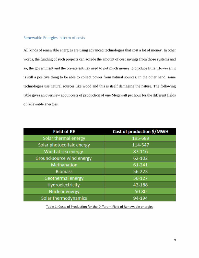
Renewable Energies in term of costs
All kinds of renewable energies are using advanced technologies that cost a lot of money. In other
words, the funding of such projects can accede the amount of cost savings from those systems and
so, the government and the private entities need to put much money to produce little. However, it
is still a positive thing to be able to collect power from natural sources. In the other hand, some
technologies use natural sources like wood and this is itself damaging the nature. The following
table gives an overview about costs of production of one Megawatt per hour for the different fields
of renewable energies
Table 1: Costs of Production for the Different Field of Renewable energies

10
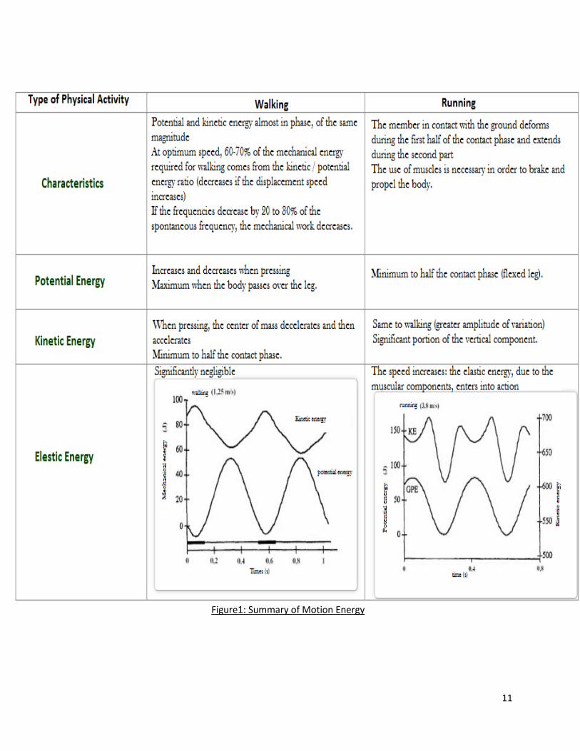
Human Locomotion and Energy released
The human body is always in motion, and therefore motion resulted from motion is released.
Walking and running are the two main activities that generate much energy in the human body.
While walking, the angle between Calves and thighs is not considerable, which means the leg
make a little bending and the elasticity energy in negligible. However, by stepping only once, the
gravity center takes the height of the person and then inclines which result in potential energy.
While these ups and downs, the center of gravity decreases and acquires speed, therefore a
discrepancy of the kinetic energy in mirror of the potential energy.
We can no longer ignore the existence of elastic energy through the race because of the leg
deferment. A phase of flight happens. Unlike when walking, the center of gravity increases more.
Speed is acquired during the descent. The potential and kinetic energies evolve in a mirror similarly
to walking. However, with values greater than the walking due to the appearance of a phase of
flight and the increase of the velocity.
11
Figure1: Summary of Motion Energy
12
Human Locomotion
The energy cost of locomotion is a noteworthy thing is human energy spending plans. For instance,
Passmore and Durnin (1995) computed that strolling represented 20% of the week after week
energy consumption of agent who strolled 9 hours every week, and 27% of the substantially more
noteworthy energy use of coal mineworker who strolled for 21 hours every week. The lifestyles of
these illustrations were obviously altogether different from these early people, however
locomotion should likewise be a noteworthy cost in the energy spending plans of seeker gatherer
populace. It appears to be likely that locomotion was essential likewise in the energy spending
plans of early people. It in this manner appears to be sensible to assume that human development
may have been firmly impacted by determination for structures and examples of development that
lessen the energy cost of locomotion. Advance, it appears that each of us has learned energy-
sparing practices and examples of development by experimentation. We don't generally carry on
in energy-sparing ways (in reality, a significant number of us purposely take work out), however
we have figured out how to spare energy when we wish to do as such. This capstone venture is
about the energy expenses of human strolling and running, about how our strides appear to be
adjusted to limit energy costs, and about how we ought to arrange excursions to keep costs as low
as could reasonably be expected. Also this capstone project mainly cares about the a technics that
translates human motion (walking and running) to an electrical energy.
13
FootStep
The objective of this project is about creating the electrical energy by utilizing the weight energy
or the human body mass, one can just stuns by knowing how much energy a man can have by
essentially strolling on the ground with an ordinary speed. As individuals' means (thousands upon
thousands a day) use and channel active energy excessively [1]. At whatever point a man strolls,
figures out how to lose energy towards the ground by method for impact, vibration, and sound and
soon, an aftereffect of the move of overabundance weight to the floor. That energy might be
utilized and changed over into electrical energy. The genuine electro-motor ground is truly a way
to deal with making electrical energy by utilizing the active energy of the individual who strolls
on the floor. The power ground dislike conventional floor. The energy delivered by this ground
will be condition agreeable without having exhaust cloud. Delivering this kind of energy will be
financially savvy moreover. The power ground does not require any fuel or maybe any kind of
energy asset, just making utilization of motor energy. Based upon your abundance weight from a
man proceeding onward the ground.
14
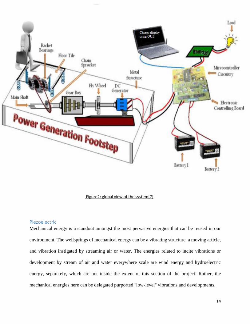
Figure2: global view of the system[7]
Piezoelectric Mechanical energy is a standout amongst the most pervasive energies that can be reused in our
environment. The wellsprings of mechanical energy can be a vibrating structure, a moving article,
and vibration instigated by streaming air or water. The energies related to incite vibrations or
development by stream of air and water everywhere scale are wind energy and hydroelectric
energy, separately, which are not inside the extent of this section of the project. Rather, the
mechanical energies here can be delegated purported ''low-level'' vibrations and developments.

15
Mechanical waste energies for the most part can be collected by utilizing vibration-to power
transformation. The most recognized normal for this sort of waste energy harvesting is at first
distinguished for low power eras. In this way, one of the focused on applications is to power little
electronic gadgets. In any case, late advancement demonstrates that it can likewise be utilized for
substantial scale applications. Vibration-to-power transformation can be acknowledged through
three essential components, including electromagnetic, electrostatic, and piezoelectric
transductions.
Among the three systems, piezoelectric transduction has gotten the best consideration. This is on
account of piezoelectric materials have bigger power densities and higher attainability for viable
applications than the materials utilized as a part of the other two systems. For instance, voltage
yields in electromagnetic energy harvesting are normally low and accordingly should be
intensified to a level adequately high to charge stockpiling gadgets. Conversely, nonetheless,
piezoelectric energy harvesters yield voltages that can be utilized specifically. In electrostatic
energy harvesting, the materials ought to be liable to an outer connected voltage to trigger the
relative vibratory movement of the capacitor components, which yields elective electrical streams.
Such outer connected voltages are required in piezoelectric energy harvesting. Another favorable
position over electromagnetic gadgets is that piezoelectric harvesting gadgets can be manufactured
at both full scale and smaller scale, because of the entrenched testimony systems for thick-movies
and thin-movies piezoelectric.

16
The configuration of the tiles
Quartz Power Devices are prescribed for dynamic power functions. They are not utilized as 'load
cells' for motionless (static) functions. Quick reaction, roughness, solidness equivalent to strong
steel, stretched out extents and the capacity to likewise gauge semi-static powers are standard
elements related with PCB quartz power devices.
The accompanying data introduces a portion of the plan and working attributes of PCB power
devices to help you better see how they work, which thusly, will "help you improve dynamic
estimations".
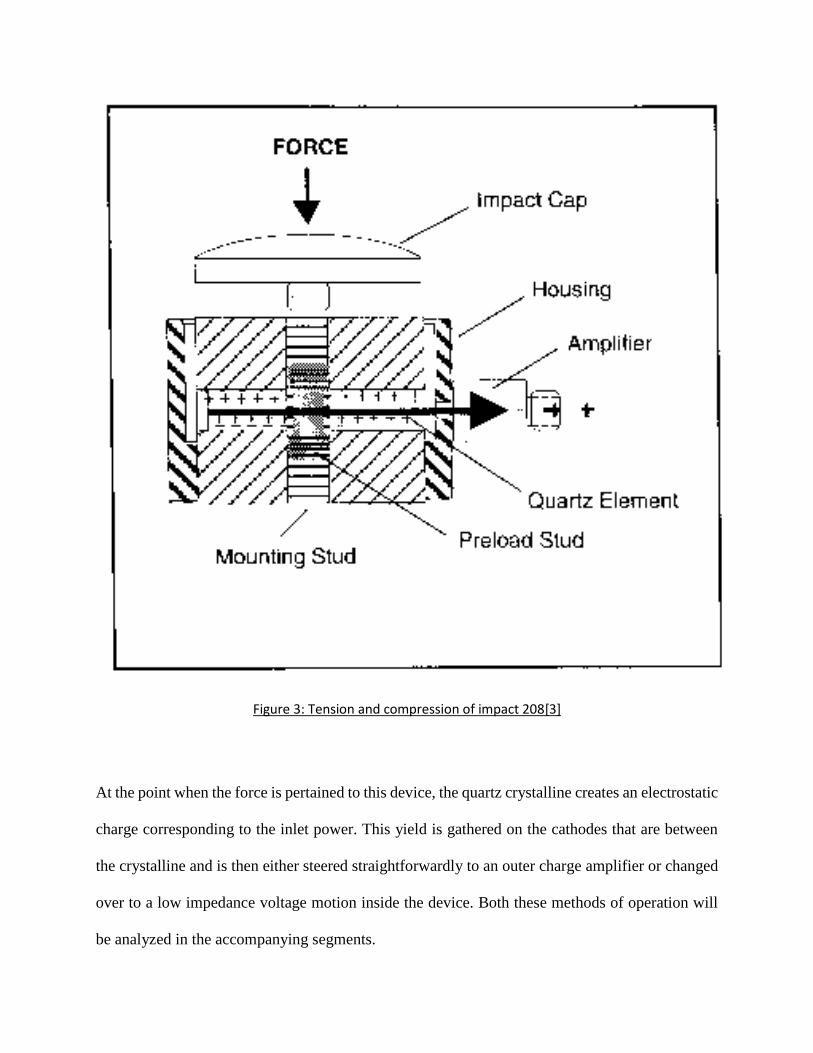
Figure 2, shows the cross-area of a run of the mill quartz power device. This specific device is a
General Purpose 208 Series pressure/strain show with inherent gadgets.
17
Figure 3: Tension and compression of impact 208[3]
At the point when the force is pertained to this device, the quartz crystalline creates an electrostatic
charge corresponding to the inlet power. This yield is gathered on the cathodes that are between
the crystalline and is then either steered straightforwardly to an outer charge amplifier or changed
over to a low impedance voltage motion inside the device. Both these methods of operation will
be analyzed in the accompanying segments.
18
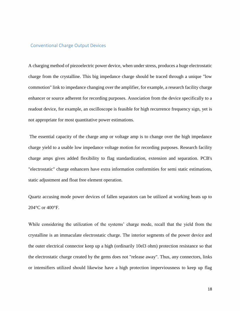
Conventional Charge Output Devices
A charging method of piezoelectric power device, when under stress, produces a huge electrostatic
charge from the crystalline. This big impedance charge should be traced through a unique "low
commotion" link to impedance changing over the amplifier, for example, a research facility charge
enhancer or source adherent for recording purposes. Association from the device specifically to a
readout device, for example, an oscilloscope is feasible for high recurrence frequency sign, yet is
not appropriate for most quantitative power estimations.
The essential capacity of the charge amp or voltage amp is to change over the high impedance
charge yield to a usable low impedance voltage motion for recording purposes. Research facility
charge amps gives added flexibility to flag standardization, extension and separation. PCB's
"electrostatic" charge enhancers have extra information conformities for semi static estimations,
static adjustment and float free element operation.
Quartz accusing mode power devices of fallen separators can be utilized at working heats up to
204°C or 400°F.
While considering the utilization of the systems’ charge mode, recall that the yield from the
crystalline is an immaculate electrostatic charge. The interior segments of the power device and
the outer electrical connector keep up a high (ordinarily 10el3 ohm) protection resistance so that
the electrostatic charge created by the gems does not "release away". Thus, any connectors, links
or intensifiers utilized should likewise have a high protection imperviousness to keep up flag
19
trustworthiness. Natural contaminants, for example, dampness, soil or oil all added to lessened
protection, bringing about flag float and conflicting outcomes.
Utilization of uncommon "low clamor" link is required with charge mode power devices. Standard,
two-wire or coaxial link when flexed create an electrostatic charge between the conveyors. This is
alluded to as "triboelectric clamor" and can't be recognized from the device's precious stone
electrostatic yield. "Low clamor" links have an exceptional graphite grease between the dielectric
shields which limits the triboelectric impact.
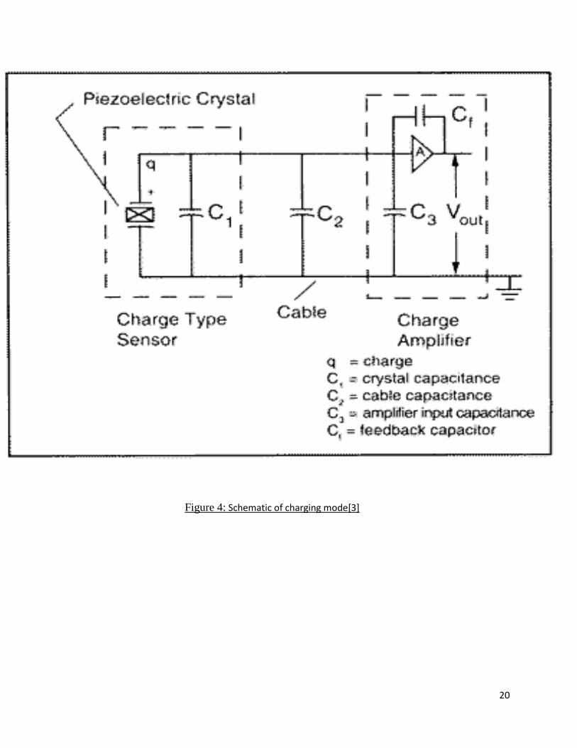
Figures 3 and 4 demonstrate a normal charge amp framework schematic including: device, low
commotion, charge intensifier and the cable.
20
Figure 4: Schematic of charging mode[3]
21
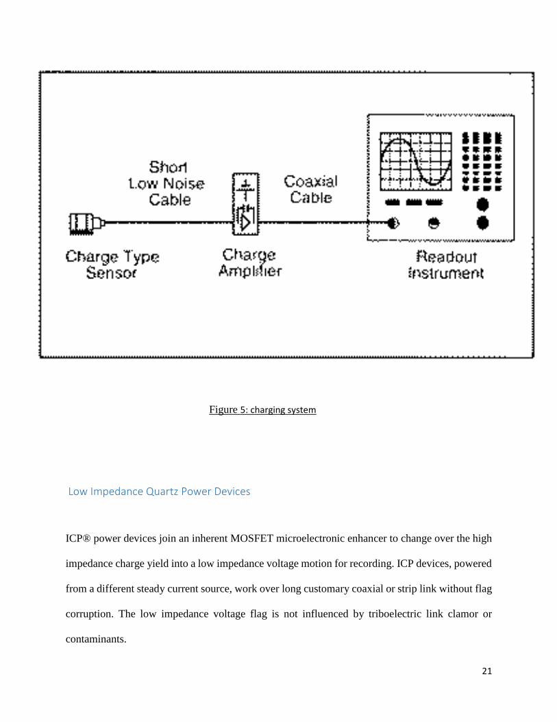
Figure 5: charging system
Low Impedance Quartz Power Devices
ICP® power devices join an inherent MOSFET microelectronic enhancer to change over the high
impedance charge yield into a low impedance voltage motion for recording. ICP devices, powered
from a different steady current source, work over long customary coaxial or strip link without flag
corruption. The low impedance voltage flag is not influenced by triboelectric link clamor or
contaminants.
22
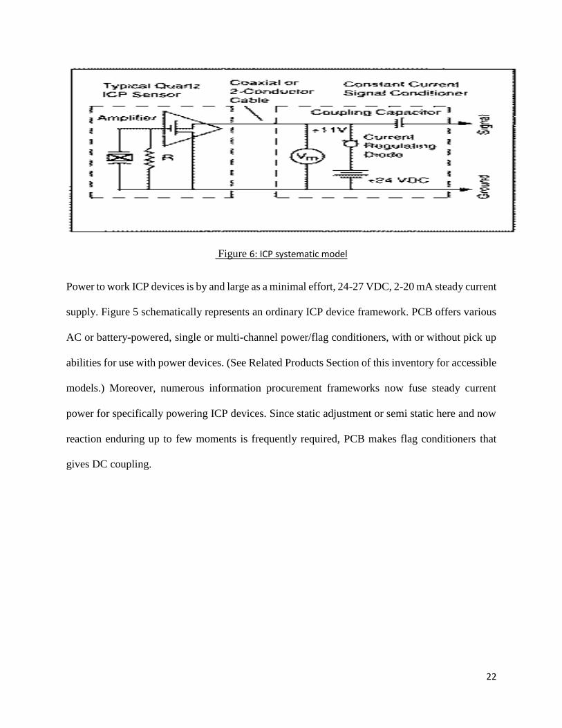
Figure 6: ICP systematic model
Power to work ICP devices is by and large as a minimal effort, 24-27 VDC, 2-20 mA steady current
supply. Figure 5 schematically represents an ordinary ICP device framework. PCB offers various
AC or battery-powered, single or multi-channel power/flag conditioners, with or without pick up
abilities for use with power devices. (See Related Products Section of this inventory for accessible
models.) Moreover, numerous information procurement frameworks now fuse steady current
power for specifically powering ICP devices. Since static adjustment or semi static here and now
reaction enduring up to few moments is frequently required, PCB makes flag conditioners that
gives DC coupling.
23
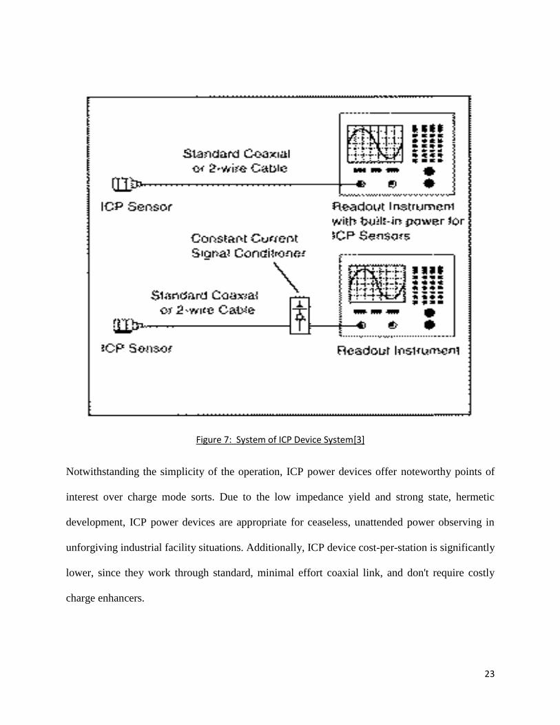
Figure 7: System of ICP Device System[3]
Notwithstanding the simplicity of the operation, ICP power devices offer noteworthy points of
interest over charge mode sorts. Due to the low impedance yield and strong state, hermetic
development, ICP power devices are appropriate for ceaseless, unattended power observing in
unforgiving industrial facility situations. Additionally, ICP device cost-per-station is significantly
lower, since they work through standard, minimal effort coaxial link, and don't require costly
charge enhancers.
24
Polarity
The outlet voltage polarity of the lCP power devices is certain for pressure and negative for strain
power estimations. The PCB charge mode power devices’ polarity is recently inverse: negative for
pressure and positive for strain. This is on the grounds that charge yield devices are normally
utilized with outside charge enhancers that show a transforming trademark. Accordingly, the
subsequent framework yield polarity of the charge enhancer framework is certain for pressure and
negative for strain; same with respect to an ICP device framework. (Turn around polarity devices
are likewise accessible.)
Why Only Dynamic Power Can Be Measured With Piezoelectric Power Devices?
The piezoelectric crystals power device produce an electrostatic charge just when power is
connected to or expelled from them. Be that as it may, despite the fact that the electrical protection
resistance is very expansive. By the end, the electrostatic charge will break to zero through the
most minimal resistant way. As a result, on the off chance that you apply a static power to a
piezoelectric power device, the electrostatic charge yield at first produced will inevitably spill back
to zero.
The rate at which the charge spills back to zero is subject to the most reduced protection resistance
way in the device, link and the electrical resistance/capacitance of the intensifier utilized.
In a charge mode power device, the spillage rate is normally settled by estimations of capacitance
and resistance in the low commotion link and outer charge or source adherent speaker utilized.
In a powering device with implicit ICP gadgets, the resistance and capacitance of the inherent ICP
hardware regularly decides the spillage rate.
25
At the point when a fast element power is connected to a piezoelectric power device, the
electrostatic charge is created rapidly and, with a sufficient release time consistent, does not spill
back to zero. Be that as it may, there is a time when a moderate speed dynamic power ends up
noticeably semi static and the spillage is speedier than the rate of the evolved power. Where is the
time when the power is too moderate for the piezoelectric power device to make the estimation?
See the following segment on Discharge Time Constant for the appropriate response.
DTC Charge Mode System
While the system is in charge mode, the devices don't comprise in-built amps, in this way, the
DTC is normally controlled by the settings on an outside charge amp. An input resistor cooperating
with a capacitor on the operational intensifier decides the time steady. PCB Series 460 Charge
Amplifiers includes short, medium and long time consistent change from which DTC is chosen. It
is expected that the electrical protection resistance of the power device and link interfacing with
the charge speaker are bigger than that of the input resistor in the charge intensifier; generally,
float will happen. Hence, to guarantee this, the power device association point and link must be
kept perfect and dry.
Low Frequency Response of ICP Systems
With ICP devices, there are two components which must be considered when making low
recurrence dimensions. These are:
1.) The release time consistent normal for the power device.
2.) The release time consistent of the AC coupling circuit utilized as a part of the flag conditioner.
(In the event that DC coupling is utilized, just the over (1) should be considered.)

26
It is imperative to comprehend both components to guarantee precise low recurrence dimensions
for the client.
DTC in ICP Power tiles
The segments in the ICP devices inner amp settles the DTC. Particulars for the ICP power devices
appeared in this list of the DTC for each power device.
When testing with ICP devices, there are two time constants that must be considered for low
recurrence assurance, one being that of the device which is a settled esteem, and the other that of
the coupling electrical circuit utilized as a part of the flag conditioner.
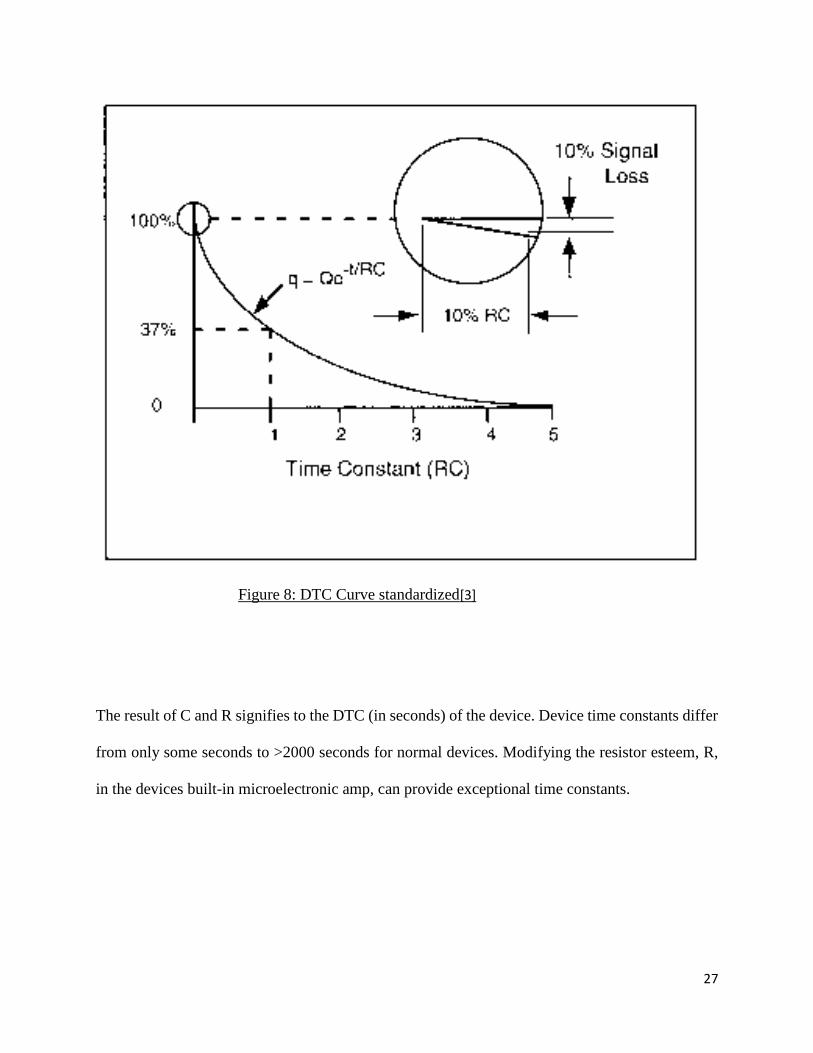
At the point when an ICP device is subjected to a stage work input, an amount of charge, Δq, is
created relative to the mechanical info. As per the law of electrostatics, yield voltage is ΔV = Δq/C
where C is the aggregate capacitance of the detecting component, intensifier, and going capacitor.
The MOSFET intensifier to decide last device affectability then intensifies this voltage. After the
underlying stride input, the charge flag rots as indicated by the condition q = Qe-t/RC where:
the graphical representation of this equation in Fig. 7 below:
27
Figure 8: DTC Curve standardized[3]
The result of C and R signifies to the DTC (in seconds) of the device. Device time constants differ
from only some seconds to >2000 seconds for normal devices. Modifying the resistor esteem, R,
in the devices built-in microelectronic amp, can provide exceptional time constants.

28
Most display tools have a huge input impedance >1 Mega-ohm. For these kinds of systems, the
device DTC, as discussed in previous sections, becomes an important value, also can be utilized
as a discharge signal rate. Be that as it may, for signs coupled to a minimum impedance outlet
devices, larger <1 Mega-ohm, it is important to know the time constant of our system. This will
be clarified in the next part.
Signal Conditioner & Readout Time Constants:
The outer power supply utilized with an ICP power device may likewise have a DTC related with
it. In various ICP signal suppliers, which include inner cradle enhancers or pick up amps, the time
is settled by different inside parts and might be shorter, or more, than the device DTC. The
capacitive outputs are not constant when it comes to the DTC. For this situation, a capacitor used
to separate the coupling an ICP power device predisposition voltage acts with the information
impedance of the readout device to make some other time consistent.
Check the details of the indicator of the conditioner to decide whether it has a settled inside DTC,
which sets the low recurrence reaction, or in the event that has a capacitive-coupled yield. In the
event that the yield is capacitive-coupled, the time consistent, when nourished into the contribution
of the readout can be computed as takes after:
DTC = Estimation of power supply coupling capacitor * Input impedance of readout
29
Take note of that the income of some ICP conditioners highlight (capacitive-coupled power) a
shunt resistor that supersedes the impacts of the info resistance of the readout device in the event
that it is 1 Mega-ohm or more noteworthy.
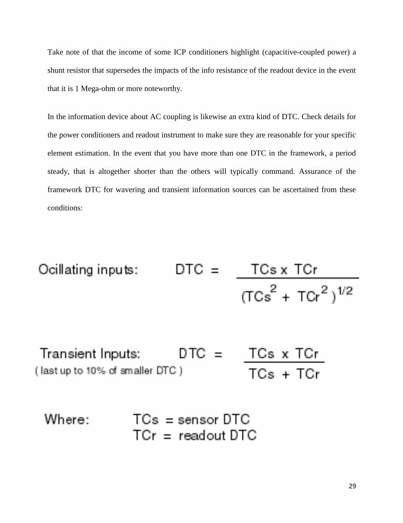
In the information device about AC coupling is likewise an extra kind of DTC. Check details for
the power conditioners and readout instrument to make sure they are reasonable for your specific
element estimation. In the event that you have more than one DTC in the framework, a period
steady, that is altogether shorter than the others will typically command. Assurance of the
framework DTC for wavering and transient information sources can be ascertained from these
conditions:
30
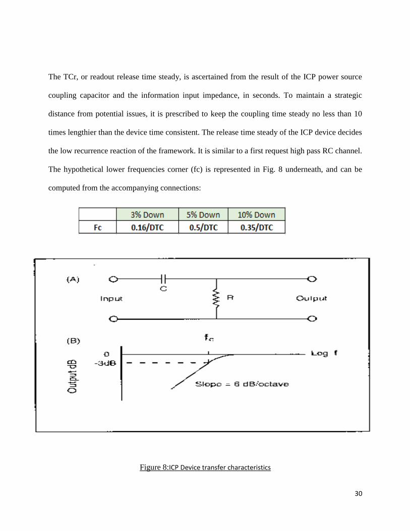
The TCr, or readout release time steady, is ascertained from the result of the ICP power source
coupling capacitor and the information input impedance, in seconds. To maintain a strategic
distance from potential issues, it is prescribed to keep the coupling time steady no less than 10
times lengthier than the device time consistent. The release time steady of the ICP device decides
the low recurrence reaction of the framework. It is similar to a first request high pass RC channel.
The hypothetical lower frequencies corner (fc) is represented in Fig. 8 underneath, and can be
computed from the accompanying connections:
Figure 8:ICP Device transfer characteristics

31
Long Duration Events and DTC It is frequently coveted to gauge an info beat enduring a limited seconds in term. This is
particularly valid with power device applications where static adjustment or semi static estimations
happen. (Before doing trial of this nature, it is critical to DC couple the whole checking system to
anticipate quick signals. PCB 484 Series conditioners have AC/DC method of operation and are
intended for such applications.)
The general dependable guideline for such estimations is that the yield of the lost signal and time
slipped by over the initial 10% of DTC that have a coordinated relationship. On the off chance that
a device has a 500 per second DTC, over the initial 50 seconds, 10% of the first signal for the input
will have rotted. For 1% exactness, information ought to be taken in the initial 1% of the DTC. In
the event that 8% exactness is worthy, the estimation ought to be taken inside 8% of the DTC.
Figure 9 graphically exhibits this occasion.
32
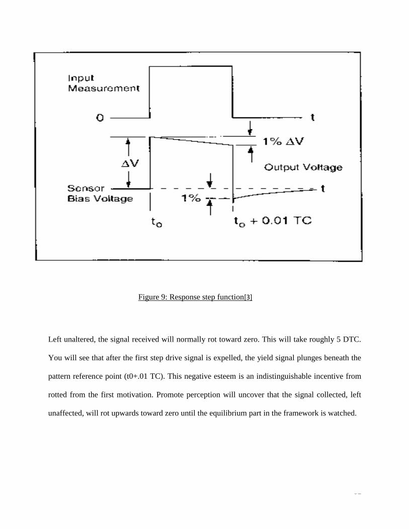
Figure 9: Response step function[3]
Left unaltered, the signal received will normally rot toward zero. This will take roughly 5 DTC.
You will see that after the first step drive signal is expelled, the yield signal plunges beneath the
pattern reference point (t0+.01 TC). This negative esteem is an indistinguishable incentive from
rotted from the first motivation. Promote perception will uncover that the signal collected, left
unaffected, will rot upwards toward zero until the equilibrium part in the framework is watched.

33
Installation:
Legitimate installation of devices is basic for defining element estimations. Albeit rough PCB
quartz power devices are pardoning to some extends, but certain fundamental methods ought to be
taken after.
As most PCB power devices are intended with quartz pressure plates to quantify powers connected
in a hub heading, adjusting the device and contact surfaces to avert edge stacking or twisting
minutes in the device will create better element estimations.
Having parallelism between the device and test structure contact surfaces limits twisting minutes
and edge stacking. Evenness of surfaces will likewise influence the nature of the estimation.
Utilizing a thin layer of oil on mounting surfaces amid establishment, makes better contact
amongst device and rising surface.
The increasing surfaces on PCB power devices are lapped amid their fabrication to guarantee that
they are parallel, plate, and horizontal. Ring-styled power devices are provided with antifriction
washers to limit shear stacking of the device surface while torqueing between the two surfaces.
Stacking to the whole power device-detecting surface is likewise essential for good estimations.
Be that as it may, this can be troublesome if the surface being carried into contact with the device
dos not have a similar rise surface. For this situation, a middle of the road bended surface ran
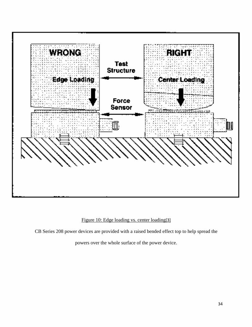
reduces edge stacking influences. (See Figure 10)
34
Figure 10: Edge loading vs. center loading[3]
CB Series 208 power devices are provided with a raised bended effect top to help spread the
powers over the whole surface of the power device.

35
One other issue when mounting power devices is attempting to limit pointless mechanical high
recurrence stun stacking of the devices. The high recurrence substance of direct metal-to-metal
effects can frequently make brief term, high "g" over-burdens in structures and devices. This issue
can be limited by using a thin damping layer of a gentler material on the interface surface between
the structure and device being affected. (It ought to be considered in advance whether the slight
damping of the high recurrence stun is basic to the power estimation prerequisites.) The effect
surface on Series 200 and the effect tops on Series 208 Power Devices are provided by thin layers
that are affecting the material negatively.
Preloading Power Rings
PCB ring style power devices are introduced between two sections of a test structure with a
flexible beryllium copper jolt or stud. This stud holds the structure together and applies preload to
the power ring. In this kind of establishment, some portion of the power between the two structures
is shunted through the mounting stud. This might be up to 5% for the beryllium copper stud
provided with the instrument and up to half for steel studs. On the off chance that a stud other than
beryllium copper is utilized, it is vital that ring devices be aligned in a preloaded state to guarantee
exact readings and linearity all through the whole working scope of the device.
36
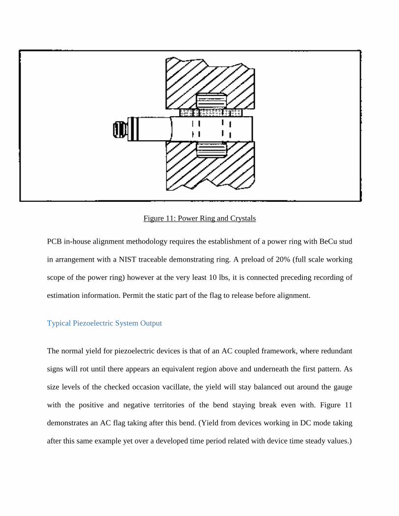
Figure 11: Power Ring and Crystals
PCB in-house alignment methodology requires the establishment of a power ring with BeCu stud
in arrangement with a NIST traceable demonstrating ring. A preload of 20% (full scale working
scope of the power ring) however at the very least 10 lbs, it is connected preceding recording of
estimation information. Permit the static part of the flag to release before alignment.
Typical Piezoelectric System Output
The normal yield for piezoelectric devices is that of an AC coupled framework, where redundant
signs will rot until there appears an equivalent region above and underneath the first pattern. As
size levels of the checked occasion vacillate, the yield will stay balanced out around the gauge
with the positive and negative territories of the bend staying break even with. Figure 11
demonstrates an AC flag taking after this bend. (Yield from devices working in DC mode taking
after this same example yet over a developed time period related with device time steady values.)

37
Illustration: Assuming a 0 to 4 volt yield flag is created from an AC coupled power application
with a one moment relentless state beat rate and one moment between heartbeats. The recurrence
stays consistent yet the flag rapidly rots adversely until the flag bases on the first standard (where
range A = territory B). Top to top yield continues as before.
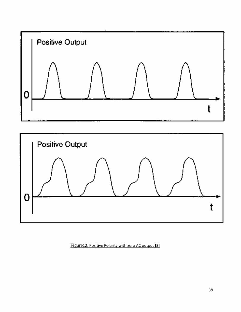
Repetitive Pulse Applications
In many power checking applications it is wanted to screen a progression of zero-to-top
monotonous heartbeats that may happen inside a brief timeframe interim of each other. This yield
flag is frequently alluded to as a "heartbeat prepare". As has been beforehand talked about, the AC
coupled yield motion from piezoelectric devices will rot towards a balance state, making it
resemble the positive power is diminishing and hard to precisely screen a constant zero-to-crest
yield flag, for example, related with stamping or pill squeeze applications. With the utilization of
uncommon ICP flag molding gear it winds up plainly conceivable to position a yield flag positive
going over a ground based zero. Working with a float free AC current, the Model PCB 484B02
gives the consistent current voltage excitation to ICP power devices and has a zero based cinching
circuit that electronically resets zero to each pulse. As illustrated in Figure 11, this exceptional
hardware keeps the yield from floating adversely giving a persistent positive signal.
38
Figure12: Positive Polarity with zero AC output [3]

39
Calibration of Power Devices
PCB gives NIST (National Institute of Standards and Technology) traceable adjustment and testing
administrations for all power devices. Alignment methodology takes after acknowledged rules as
suggested by ANSI (American National Standards Institute) and ISA (instrument Society of
America). Alignment of power devices at PCB is as per ISA-37-10 and consents to MIL-STD-
45662A. These gauges give the foundation and administrate the finished alignment frameworks,
in this manner the controlling of the precision of a device's particulars is by controlling, measuring
and testing hardware exactness. Each exclusively aligned power device is provided with a NIST
traceable endorsement showing adjusted affectability. Deciding the affectability of devices with
working extents from 5 000 to 100 000 lbs (22,24 to 444,8 kN) is performed by putting the power
device in a water driven press stand. In arrangement with the device is a Morehouse demonstrating
ring reference power standard chose for the working scope of the device. Reference demonstrating
rings are adjusted and guaranteed at regular intervals to check aligned esteem. A downsized test
stand is utilized for lower ran devices. Little, high affectability models are aligned by applying a
known lightweight mass, letting the flag zero, and afterward rapidly evacuating the mass. Yield
recorded is the affectability of the device. Charge mode and longer time steady devices are adjusted
by statically applying a known power and recording yield information. In every adjustment
technique, information focuses are plotted at 20% interims of the device's working extent. Each
point speaks to the normal of three separate estimations taken at that range. These arrived when
the midpoint of focuses are graphically plotted and the best straight line through zero is drawn.
Ought the adjustment to focuses to fall outside the predefined linearity as given in distributed
details, the unit comes up short alignment and rejected.

40
Business analysis
Competitor analysis Pavegen is our only market competitor. Pavegen Company has proved lately, that they are
on the track to generate energy from human steps on ground using piezoelectric materials. In fact,
while people are stepping on the ground they are losing some energy, and the idea here, is to benefit
from that lost energy and make it useful. The Pavegen Company are declaring that the tiles they
will be using in the ground are made from recyclable materials with a percentage of 90%, the
dimensions of each tile is: 0.6 m x 0.45 m. Moreover, the tiles were costing for about $4000 in the
year of 2011, $200 two years after, and the price fail down to 70 dollars per tile. We are going to
do a full analysis of energy and cost to generate energy from footsteps, even though we cannot
have an exact estimation of life expectancy of each tile, we will calculate an estimated amount of
profit. Pavegen is our first competitor, where, as stated before, they produce tiles with piezoelectric
configuration and sell them. The price for those tiles (0.6m*0.45m) was reduced nowadays to $76
(761.56 MAD) and since the floor (4m*2m) is composed of 15 tiles the $ 1140 (11423.37 MAD).
Since the manufacturer is in London and the electricity price (Kwh) is low (2.844 pence). The
following table summarizes Pavegen’s income. Where our assumption of people who will walk
every day on the floor is 35000 on Time Square in New York City.
Energy gathered (one piezoelectric system) 7 Watts
Total energy in one step 28 Watts
Cost of one step 0.00144 MAD
Total energy in Time Square/ day 98 KWatt
Total gain in Time square / day 50.4 MAD
Total energy in one year 352800 Kwatt

41
Total Gain in one year 18144 MAD
Price of the tiles
Year Tile Floor
2011 40.000 MAD 600.000 MAD
2013 2.000 MAD 30.000 MAD
2015 1.000 MAD 15000 MAD
2017 760 MAD 11.400 MAD
Time Duration of 2017: 11400 MAD / (50.4 MAD*30 Days) = 7.5 Months (7 Months and 15 days)
Table 2: Cost for Pavegen
➢ This result means that Pavegen is going to recover its expenses after 7 months and half.
However in the next part we will try to minimize the cost of the floor and maximize the benefits.
Our Suggested design
In this part, we tried to come up with a new design for the floor, in which we minimize the cost of material
and also increase the gain.
o Our design consists of a triangle shape for each tile. Only the essential tile is composed of 3
piezoelectric systematic pieces.
o The floor is 4m*2m
o Composed mainly of three elements :
▪ Recycled aluminum
▪ Piezoelectric system
▪ Galvanized Steel

42
Recycled aluminum We want to minimize the price, and for this we will use recycled aluminum sheets. Aluminum sheets will
serve as the basic floor in which the piezoelectric systems are connected. Aluminum sheet will resist to
pressure and will not be damage even the mass is high.
Figure 13: Aluminum Floor
In the market, providers only sell 2m*1m for 400 MAD
Our need requires 4 sheets of recycled aluminum and it will cost us 1600 MAD

43
Piezoelectric systems In the previous sections we’ve been talking about the piezoelectric system, and now we will use it in our
floor. The piezoelectric pieces will be used as joints this time. The triangular shape will take on
piezoelectric piece in each corner and starting this idea we will gather the triple amount of electricity
that a piezoelectric system release into the battery.
Figure 14: Piezoelectric sensor

44
Number of pieces needed 13 Pieces
Price of one piece 158.6 MAD
Shipping price for each piece 21.2 MAD
Total Price 2337.4 MAD
Table3: Pricing piezoelectric Sensors
Galvanized Steel Galvanized steel will be used to protect the system from the floor. Steel is galvanized when a coat of zinc
is applied over it. This coat of zinc is used to protect our system from natural damages so that our
piezoelectric pieces won’t need maintenance until 2 years. The sheet are deformable but not breakable.
Figure 15: Galvanized Steel
(2m*1m) sheets cost 155 MAD
(4m*2m) sheets cost 620 MAD

45
This table summarize to us the cost discussed above
Recycled aluminum 1600 MAD
Piezoelectric systematic pieces 2337.4 MAD
Galvanized steel sheets 620 MAD
Total Cost for (4m*2m) Floor 4577.4 MAD
Table 3 : Primer cost estimation of the floor
Energy Gain and emplacement suggestion • Each piezoelectric sensor generates 7 Watts once we step on it, and as each tile is placed
between 3 piezoelectric sensors, the energy collected from one step is 21 Watts.
• We suggest to put such a technology in the entrance of MOROCCO MALL as it receives much
visitors each day.
• By investigating about the number of people that enter the MALL, HuffPost Maroc reported that
18 Million people entered MOROCCO MALL last year which give us and approximation of 49315
Person.
• The piezoelectric floor is to be fixed between the security hole
• People would walk over the 4m length and by walking on it they step an average of 5 Steps.
One piezoelectric sensor 7 Watts
One tile 21 Watts
Number of people walking 49315 steps
Number of steps/ one person 3 steps
Total steps 147945 step
Total energy 310.6 Kwatt
Table 4: energy collected

46
Monetary gain Converting energy gain to a monetary gain needed the following that form the ONEE. The National Office
of Electricity and drinkable water (ONEE) of Morocco has defined different tariffs for electricity
consumption depending on the usage and masse of the consumer.
For domestically usage:
The total tariff (in Dirhams) of consumption is calculated used system of installments with VAT included
(14%):
Installment of consumption/month Watt price
0 à 100 kWh 0,0009010
101 à 150 kWh 0,0010732
151 à 200 kWh 0,0010732
201 à 300 kWh 0,0011676
301 à 500 kWh 0,0013817
> à 500 kWh 0,0015958
Massive accounts:
Fixed tariff of a Watt per year 0,49409
Tariffs per months Peaking hours 0,0013645
Full hours 0,0009736
Breaking hours 0,0007131 Table 5: Electricity billing

47
• Since we are targeting MOROCCO MALL as a consumer for our product, we will use Peaking hours
tariff and which is 0.0013645 MAD.
From this our monetary gain will be:
Monetary gain = Energy Gain*Price of one watt
517800 Watts*0.0013645=432.92 MAD/day
➢ For our daily gain we will collect a monetary value of 706.54 MAD
Expenses Recovery Duration
Time Duration: 4577.5 MAD / (432.92MAD) = 10 Days (approximately one week and half)
Comparison of both projects outcomes
Pavegen Company Capstone Project estimation
Price of the floor (15 tiles)
11423.37 MAD
Price of the floor (15 tiles)
4577.4 MAD
Energy gathered in one day
98000 Watts
Energy gathered in one day
310600 Watts
Monetary Gain per day
50.4 MAD/ day
Monetary Gain per day
432.92 MAD/day
Time duration for expenses recovery
7 Months and 15 days
Time Duration for expenses recovery
10 Days
Conclusion: more time, lower gain Conclusion: Less time, bigger gain
Table 6: Summarizing table for the Gains

48
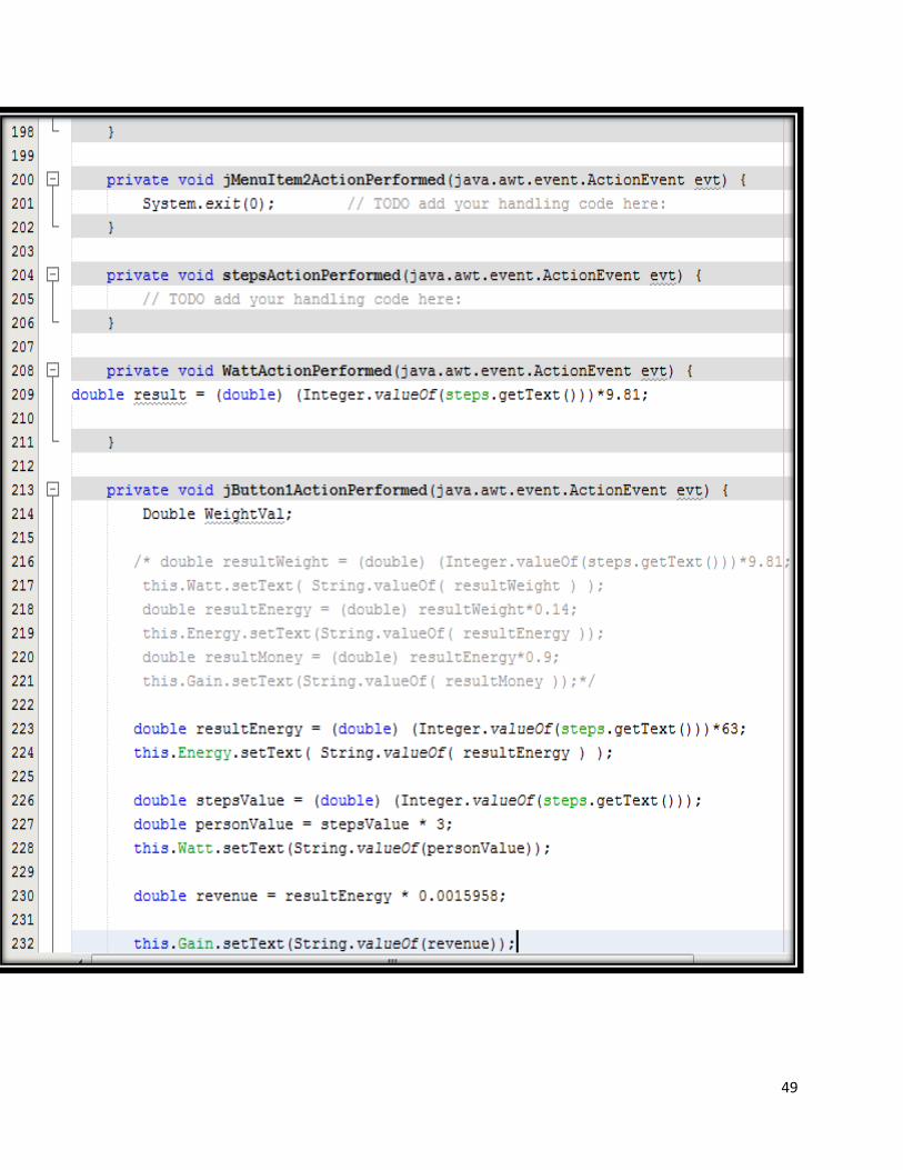
Code for energy auditing • The following Java Code is designed with NetBean to be used as an automated interface to calculate the Energy
collected and the monetary gain.
• The code “Footsteps RenewedTiles” Contains equations that we used previously in the financial part in order to
calculate our gains for our assumptions
49
50
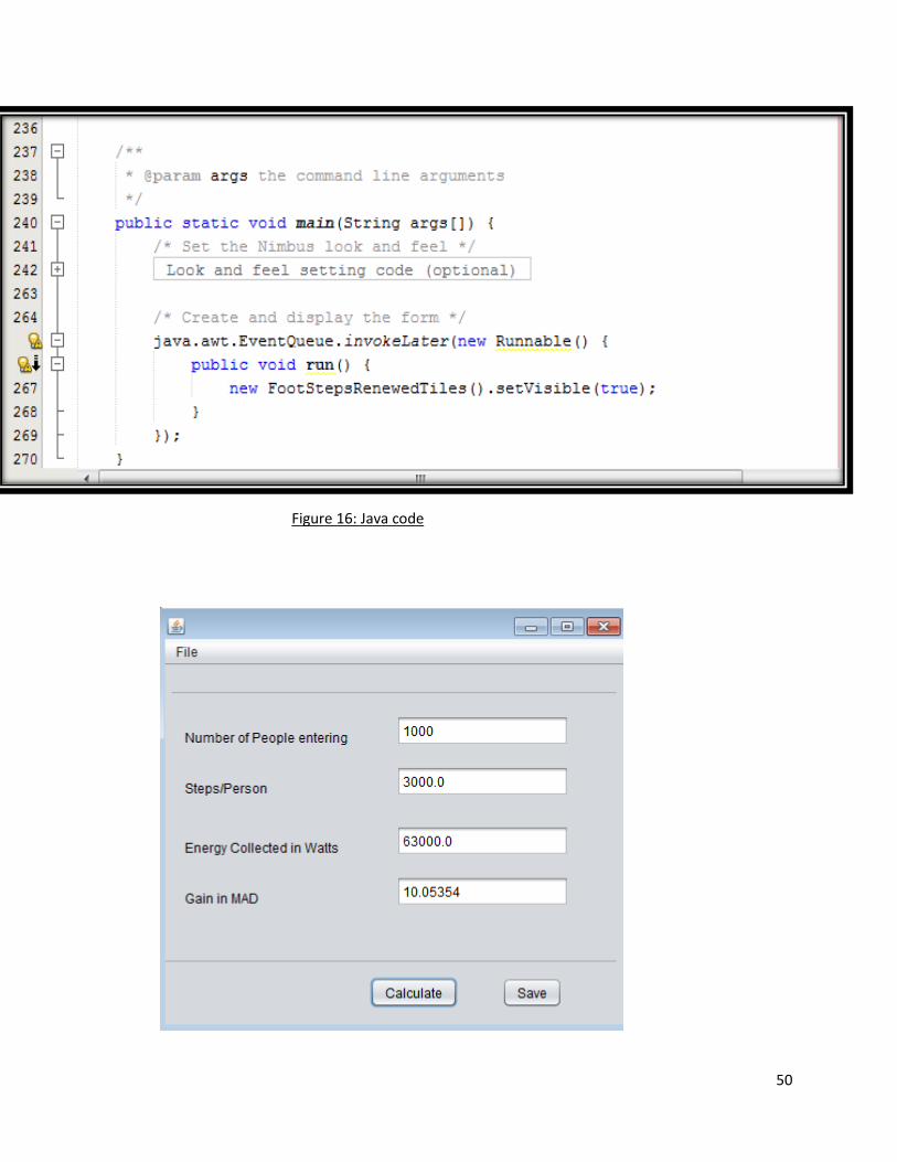
Figure 16: Java code

51
✓ In the first trial we assumed that 1000 people entered the MALL and stepped 3 times on the floor. We collected 63
Kwatts and we obtained 10.5 MAD
Figure 17: interface trial
✓ From the beginning we assumed that the average people entering MOROCCO MALL each day is 49315 people and
when calculating manually, we’ve got the same result as the Java interface.
This code is to calculate the total gains for each installed floor, where it can be used to calculate the energy audit for
the floors and if the result is not neutral, the maintenance is needed.
52
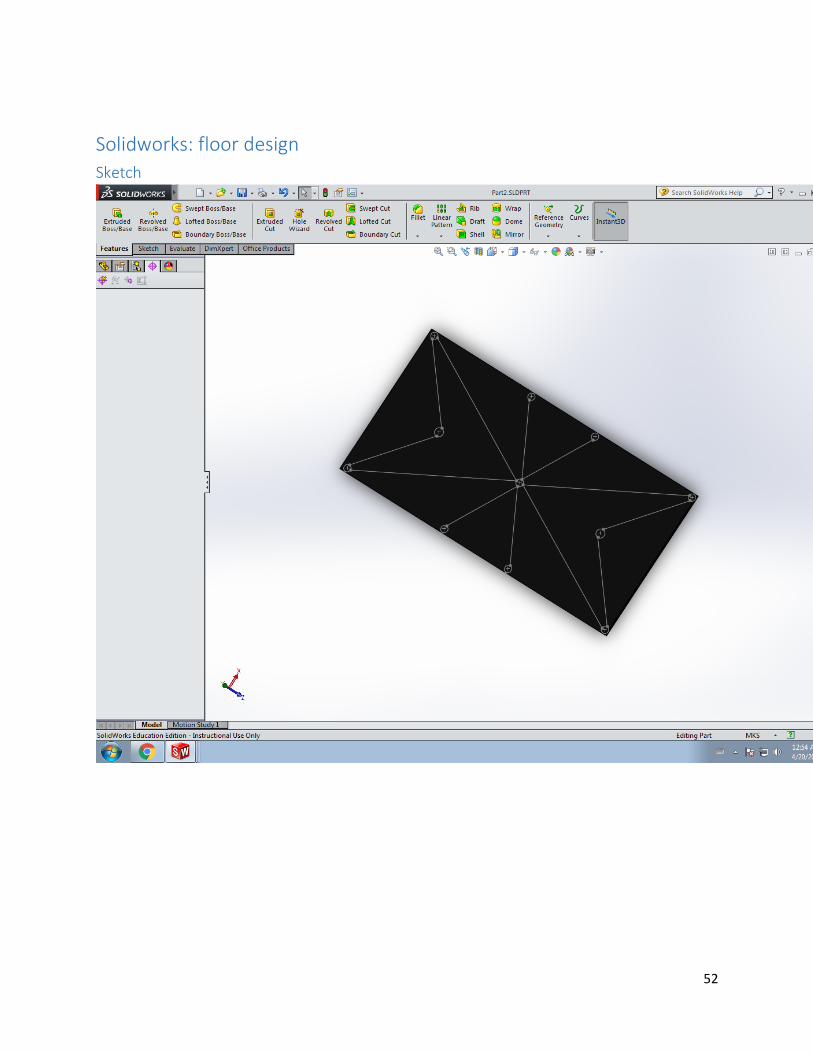
Solidworks: floor design
Sketch
53
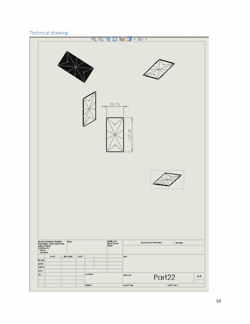
Technical drawing

54
Conclusion
Today’s demands of electricity is becoming too high due to the growth of population. All sorts of
renewable engineering technologies are trying to extract energy from natural sources. However, as we
stated at the beginning, this capstone project does not harm any natural source, in contrast energy is
collected from the human locomotion and translated into electricity stored in batteries to later uses.
This project should be wisely implemented in places like gymnasiums, markets, dance floors and most
frequented streets.

55
References
[1]. Applications of Ferroelectrics, 2004. ISAF-04. 2004 14th IEEE International Symposium on Digital
Object Identifier: 10.1109/ISAF.2004 .1418347 .Publication Year: 2004
[2]. Gautschi, G (2002). Piezoelectric Sensorics: Force, Strain, Pressure, Acceleration and Acoustic
Emission Sensors, Materials and Amplifiers
[3] "Introduction to Dynamic Pressure Sensors." Introduction to Piezoelectric Pressure Sensors. N.p., n.d. Web. 26 Apr. 2017. [4] S.S.Taliyan, B.B. Biswas, R.K. Patil and G. P. Srivastava, Reactor Control Division, Electronics & Instrumentation Group And T.K. Basu IPR, Gandhinagar [5] Center for Intelligent Material Systems and Structures Virginiav Polytechnic Institute and State University. [6] Meiling Zhu, Member, IEEE, Emma Worthington, and Ashutosh Tiwari, Member, IEEE. [7] Design Study of Piezoelectric Energy- Harvesting Devices for Generation of Higher Electrical Power Using a Coupled-Piezoelectric-Circuit Finite Element Method IEEE Transactions on Ultrasonic’s, Ferroelectrics, and Frequency Control, vol. 57, no. 2, February 2010. [8] Estimation of Electric Charge Output for Piezoelectric EnergyHarvesting,LA-UR-04-2449, Strain Journal, 40(2), 49-58, 2004;Henry A. Sodano, Daniel J. Inman, Gyuhae Park. Electricity from Footsteps [9] S.R. Anton, H.A. Sodano, A review of power harvesting using piezoelectric materials (2003–2006). Smart Mater. Struct. 16, R1–R21 (2007)
[10] Laurence Kemball-Cook, Pavegen webpage. [11] www.Aliexpress.com/piezoelectric-sensors [12]


![Press Review Spring 2011 - Al Akhawayn University · 2015-09-02 · Press Review Spring 2011 [Winner of Arqaam Capital MENA Investment Challenge, May] Al Akhawayn University | Department](https://img.pdfslide.net/doc/110x75/5e70e26ad8f6c827744c8494/press-review-spring-2011-al-akhawayn-2015-09-02-press-review-spring-2011-winner.jpg)