Embed Size (px)
Citation preview
152
15. Installation
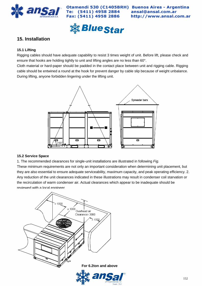
15.1 Lifting
Rigging cables should have adequate capability to resist 3 times weight of unit. Before lift, please check and
ensure that hooks are holding tightly to unit and lifting angles are no less than 60°.
Cloth material or hard-paper should be padded in the contact place between unit and rigging cable. Rigging
cable should be entwined a round at the hook for prevent danger by cable slip because of weight unbalance.
During lifting, anyone forbidden lingering under the lifting unit.
15.2 Service Space
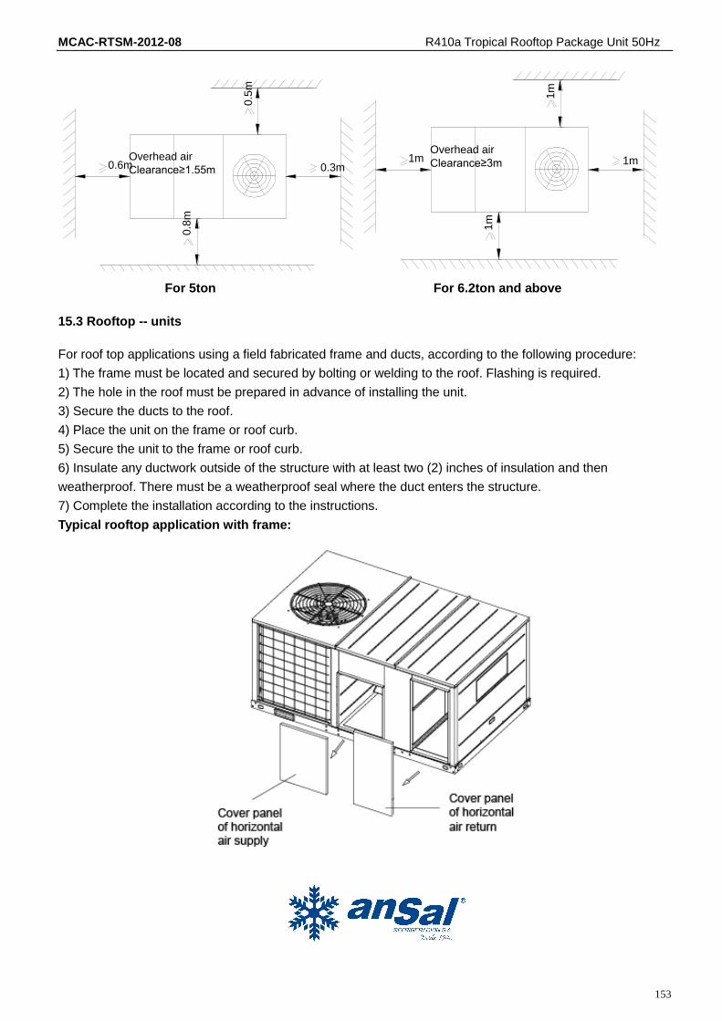
1. The recommended clearances for single-unit installations are illustrated in following Fig.
These minimum requirements are not only an important consideration when determining unit placement, but
they are also essential to ensure adequate serviceability, maximum capacity, and peak operating efficiency. 2.
Any reduction of the unit clearances indicated in these illustrations may result in condenser coil starvation or
the recirculation of warm condenser air. Actual clearances which appear to be inadequate should be
reviewed with a local engineer.
For 6.2ton and above
MCAC-RTSM-2012-08 R410a Tropical Rooftop Package Unit 50Hz
153
Overhead air
Clearance≥1.55m0.6m 0.3m
0.5
m
0.8
m
Overhead air
Clearance≥3m1m 1m
1m
1m
For 5ton For 6.2ton and above
15.3 Rooftop -- units
For roof top applications using a field fabricated frame and ducts, according to the following procedure:
1) The frame must be located and secured by bolting or welding to the roof. Flashing is required.
2) The hole in the roof must be prepared in advance of installing the unit.
3) Secure the ducts to the roof.
4) Place the unit on the frame or roof curb.
5) Secure the unit to the frame or roof curb.
6) Insulate any ductwork outside of the structure with at least two (2) inches of insulation and then
weatherproof. There must be a weatherproof seal where the duct enters the structure.
7) Complete the installation according to the instructions.
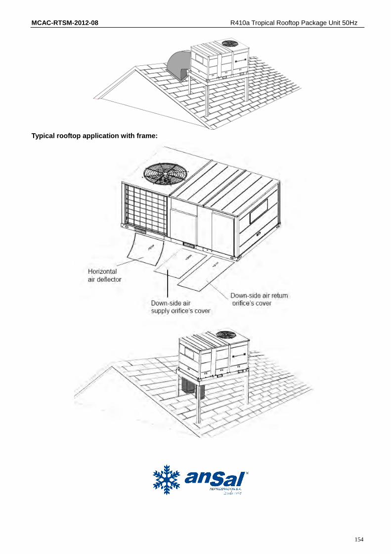
Typical rooftop application with frame:
MCAC-RTSM-2012-08 R410a Tropical Rooftop Package Unit 50Hz
154
Typical rooftop application with frame:
MCAC-RTSM-2012-08 R410a Tropical Rooftop Package Unit 50Hz
155
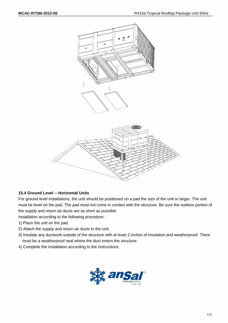
15.4 Ground Level -- Horizontal Units
For ground level installations, the unit should be positioned on a pad the size of the unit or larger. The unit
must be level on the pad. The pad must not come in contact with the structure. Be sure the outdoor portion of
the supply and return air ducts are as short as possible.
Installation according to the following procedure:
1) Place the unit on the pad.
2) Attach the supply and return air ducts to the unit.
3) Insulate any ductwork outside of the structure with at least 2 inches of insulation and weatherproof. There
must be a weatherproof seal where the duct enters the structure.
4) Complete the installation according to the instructions.
MCAC-RTSM-2012-08 R410a Tropical Rooftop Package Unit 50Hz
156
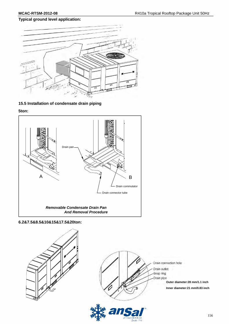
Typical ground level application:
15.5 Installation of condensate drain piping
5ton:
Drain pan
A B
Drain commutator
Drain connector tube
Removable Condensate Drain Pan
And Removal Procedure
6.2&7.5&8.5&10&15&17.5&20ton:
Outer diameter:28 mm/1.1 inch
Inner diameter:21 mm/0.83 inch
MCAC-RTSM-2012-08 R410a Tropical Rooftop Package Unit 50Hz
157
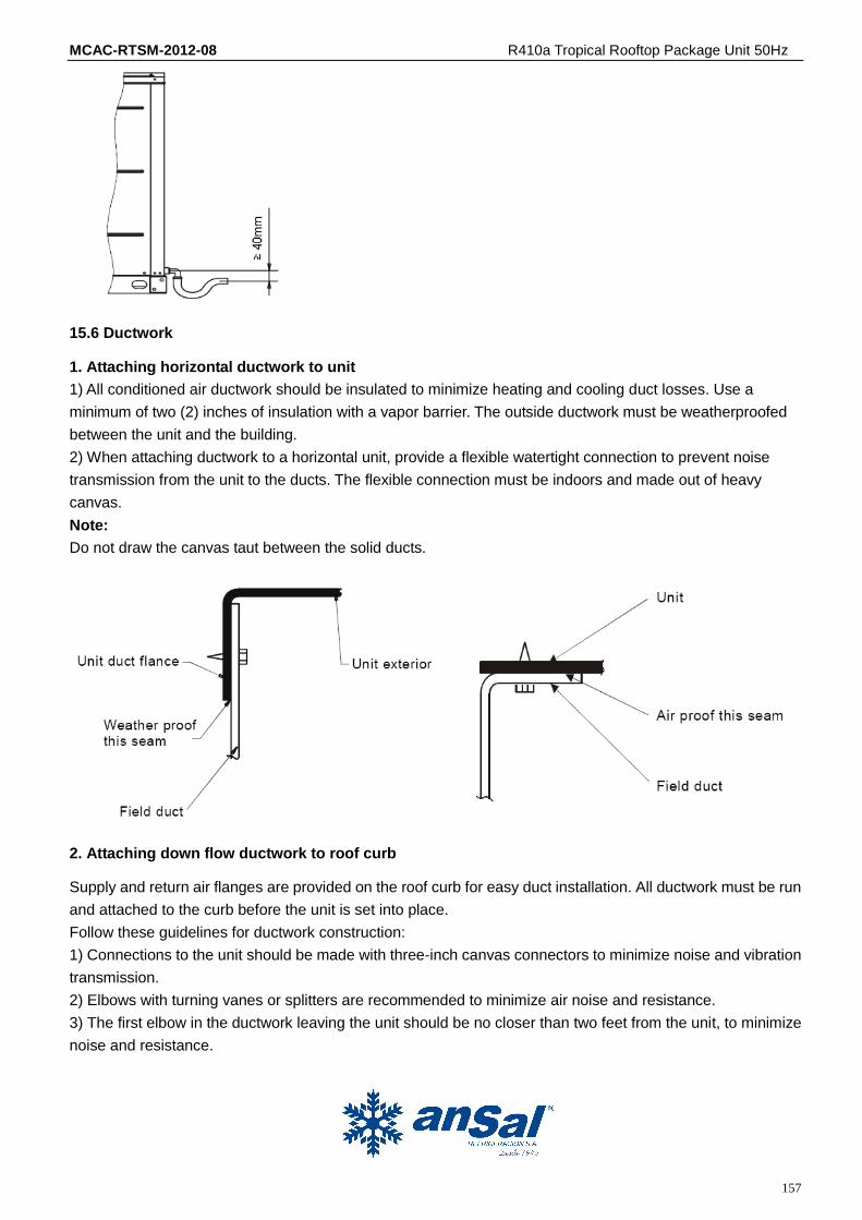
15.6 Ductwork
1. Attaching horizontal ductwork to unit
1) All conditioned air ductwork should be insulated to minimize heating and cooling duct losses. Use a
minimum of two (2) inches of insulation with a vapor barrier. The outside ductwork must be weatherproofed
between the unit and the building.
2) When attaching ductwork to a horizontal unit, provide a flexible watertight connection to prevent noise
transmission from the unit to the ducts. The flexible connection must be indoors and made out of heavy
canvas.
Note:
Do not draw the canvas taut between the solid ducts.
2. Attaching down flow ductwork to roof curb
Supply and return air flanges are provided on the roof curb for easy duct installation. All ductwork must be run
and attached to the curb before the unit is set into place.
Follow these guidelines for ductwork construction:
1) Connections to the unit should be made with three-inch canvas connectors to minimize noise and vibration
transmission.
2) Elbows with turning vanes or splitters are recommended to minimize air noise and resistance.
3) The first elbow in the ductwork leaving the unit should be no closer than two feet from the unit, to minimize
noise and resistance.

MCAC-RTSM-2012-08 R410a Tropical Rooftop Package Unit 50Hz
158
15.7 Wiring provision
Field wiring
The units are internally wired at the factory according to generally accepted electrical technology.
Required field wiring
Main power wiring to the unit control wiring between the control center and the unit, and earth wiring are
required in the field.
Required components
The following components are required: main power fuse, conduit coupling, and field supplied room
thermostat.
Wire and fuse size selection for main power source.
Wire and fuse size should be selected in accordance with national standard, taking the designed maximum
current shall be the total of the compressor maximum current, condenser fan motor current and evaporator
fan motor current (refer to “electrical data”).
Wire size between room thermostat and unit.
The wire size between the room thermostat and the unit should be determined according to the following
table, because the 24V power source is applied to the control circuit.
5Ton 6.2&7.5&8.5&10Ton 15&17.5&20Ton

MCAC-RTSM-2012-08 R410a Tropical Rooftop Package Unit 50Hz
159
16 Wired Controller
16.1 Standard wired controller: KJR-12B/DP (T)-E
KJR-12B/DP (T)-E
1. SAFETY PRECAUTIONS
The following contents are stated on the product and the operation manual, including usage, precautions
against personal harm and property loss, and the methods of using the product correctly and safely. After fully
understanding the following contents (identifiers and icons), read the text body and observe the following
rules.
Identifier description
MCAC-RTSM-2012-08 R410a Tropical Rooftop Package Unit 50Hz
160
2. SUMMARIZE
Usage condition:
○1 . Power supply: 5V DC.
○2 . Operation temperature: -15℃-+43℃.
○3 . Operation humidity: 40%-90%, RH.
3. FUNCTION SUMMARY
Main function:
○1 . Connecting to indoor unit by A, B, C, D, E terminal;
○2 . Button setting action mode.
○3 . LCD display.
○4 . Timer for rest time.
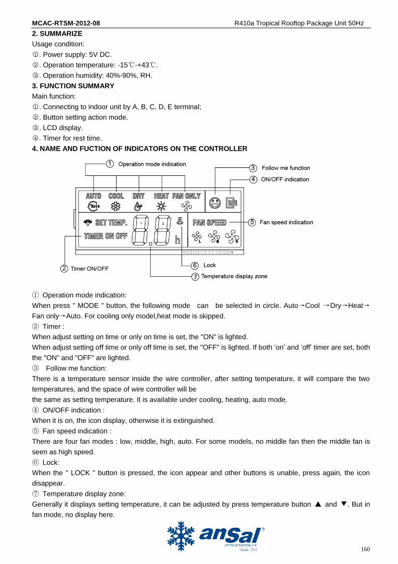
4. NAME AND FUCTION OF INDICATORS ON THE CONTROLLER
① Operation mode indication:
When press " MODE " button, the following mode can be selected in circle. Auto→Cool →Dry→Heat→
Fan only→Auto. For cooling only model,heat mode is skipped.
② Timer :
When adjust setting on time or only on time is set, the "ON" is lighted.
When adjust setting off time or only off time is set, the "OFF" is lighted. If both „on‟ and „off‟ timer are set, both
the "ON" and "OFF" are lighted.
③ Follow me function:
There is a temperature sensor inside the wire controller, after setting temperature, it will compare the two
temperatures, and the space of wire controller will be
the same as setting temperature. It is available under cooling, heating, auto mode.
④ ON/OFF indication :
When it is on, the icon display, otherwise it is extinguished.
⑤ Fan speed indication :
There are four fan modes : low, middle, high, auto. For some models, no middle fan then the middle fan is
seen as high speed.
⑥ Lock:
When the " LOCK " button is pressed, the icon appear and other buttons is unable, press again, the icon
disappear.
⑦ Temperature display zone:
Generally it displays setting temperature, it can be adjusted by press temperature button ▲ and ▼. But in
fan mode, no display here.
MCAC-RTSM-2012-08 R410a Tropical Rooftop Package Unit 50Hz
161
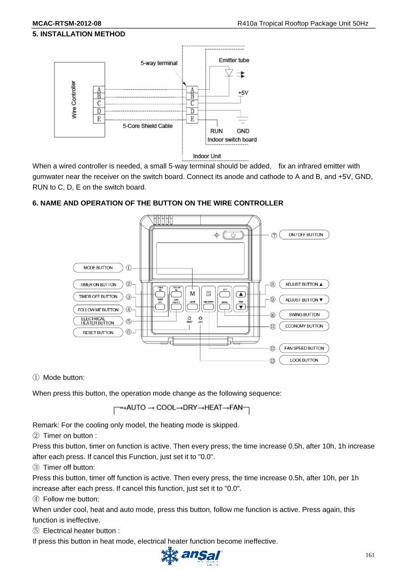
5. INSTALLATION METHOD
When a wired controller is needed, a small 5-way terminal should be added, fix an infrared emitter with
gumwater near the receiver on the switch board. Connect its anode and cathode to A and B, and +5V, GND,
RUN to C, D, E on the switch board.
6. NAME AND OPERATION OF THE BUTTON ON THE WIRE CONTROLLER
① Mode button:
When press this button, the operation mode change as the following sequence:
Remark: For the cooling only model, the heating mode is skipped.
② Timer on button :
Press this button, timer on function is active. Then every press, the time increase 0.5h, after 10h, 1h increase
after each press. If cancel this Function, just set it to "0.0".
③ Timer off button:
Press this button, timer off function is active. Then every press, the time increase 0.5h, after 10h, per 1h
increase after each press. If cancel this function, just set it to "0.0".
④ Follow me button:
When under cool, heat and auto mode, press this button, follow me function is active. Press again, this
function is ineffective.
⑤ Electrical heater button :
If press this button in heat mode, electrical heater function become ineffective.
MCAC-RTSM-2012-08 R410a Tropical Rooftop Package Unit 50Hz
162
⑥ Reset button(hidden):
Use a 1mm stick to press in the little hole , then the current setting is canceled . The wired controller will enter
into original state.
⑦ON/OFF button:
When in off state, press this button, the indicator is on, the wire controller enter into on state, and send
setting information to in door PCB. When in on state, press this button, the indicator is off, and send
instruction. If timer on or timer off has been set, it cancel this setting then send instruction to stop the
machine.
⑧ Adjust button ▲:
Set indoor temperature up. If press and hold on, it will increase at 1 degree per 0.5 second.
⑨ Adjust button ▼ :
Set indoor temperature down. If press and hold on, it will decrease at 1degree per 0.5 second.
⑩ Swing button:
First pressing: start swing function; second pressing: stop swing. (Match to some model with swing function).
○11 Economy operation button:
Press this button, the indoor unit operates in economy mode, press it again, exit this mode (it may be
ineffective for some models)
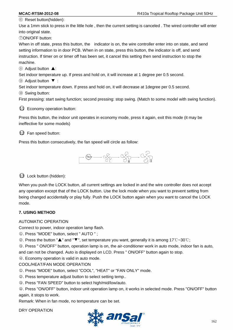
○12 Fan speed button:
Press this button consecutively, the fan speed will circle as follow:
○13 Lock button (hidden):
When you push the LOCK button, all current settings are locked in and the wire controller does not accept
any operation except that of the LOCK button. Use the lock mode when you want to prevent setting from
being changed accidentally or play fully. Push the LOCK button again when you want to cancel the LOCK
mode.
7. USING METHOD
AUTOMATIC OPERATION
Connect to power, indoor operation lamp flash.
○1 . Press "MODE" button, select " AUTO " ;
○2 . Press the button "▲" and "▼", set temperature you want, generally it is among 17℃~30℃;
○3 . Press " ON/OFF" button, operation lamp is on, the air-conditioner work in auto mode, indoor fan is auto,
and can not be changed. Auto is displayed on LCD. Press " ON/OFF" button again to stop.
○4 . Economy operation is valid in auto mode.
COOL/HEAT/FAN MODE OPERATION
○1 . Press "MODE" button, select "COOL", "HEAT" or "FAN ONLY" mode.
○2 . Press temperature adjust button to select setting temp..
○3 . Press "FAN SPEED" button to select high/mid/low/auto.
○4 . Press "ON/OFF" button, indoor unit operation lamp on, it works in selected mode. Press "ON/OFF" button
again, it stops to work.
Remark: When in fan mode, no temperature can be set.
DRY OPERATION
MCAC-RTSM-2012-08 R410a Tropical Rooftop Package Unit 50Hz
163
○1 . Press " MODE " button, select " DRY " mode.
○2 . Press temperature adjust button to select setting temp.
○3 . Press " ON/OFF " button, indoor unit operation lamp on, it works in dry mode. Press ON/OFF button again,
it stops to work.
○4 . In dry mode, economy operation and fan speed are ineffective.
TIMER SETTING
Timer on only:
○1 . Press " TIME ON " button, it display "SET" on LCD, and display " H " and "ON" , it is waiting for timer on
setting.
○2 . Press " timer " on button repeatedly to adjust time setting.
○3 . If press this button and hold on, the time will increase at 0.5h, after 10h, it increases at 1h.
○4 . After setting 0.5 second, the wire controller send timer on information, it is finished.
Timer off only:
○1 . Press "TIME OFF " button, it display "SET" on LCD, and display " H " and ON, it is waiting for timer on
setting.
○2 . Press "TIME OFF" button repeatedly to adjust time setting.
○3 . If press this button and hold on, the time will increase at 0.5h, after 10h, it increases at 1h.
○4 . After setting 0.5 second, the wire controller send timer off information, it is finished.
TIMER ON AND TIMER OFF BOTH
○1 . Set timer on time as the corresponding step1 and 2.
○2 . Set timer off time as the corresponding step1 and 2.
○3 . Timer off time must be longer than timer on time.
○4 . 0.5 second after setting, the wire controller send information, the setting is finished.
CHANGE TIMER
If there is a timer of changing time to be need, press corresponding button to revise it. If cancel timer, change
time to 0.0.
NOTE: The timer time is relative time, that is delay after setting time ( i, e: setting time is 8:05 A,M). So when
timer is set, the standard time can not be adjusted.
8. TECHNICAL INDICATION AND REQUIREMENT
EMC and EMI comply with the CE certification requirements.

MCAC-RTSM-2012-08 R410a Tropical Rooftop Package Unit 50Hz
164
16.2 Optional wired controller:
KJR-23B: For cooling only and cooling with auxiliary heater
KJR-25B: For Cooling and heating
KJR-23B KJR-25B
16.3 Field wiring
To connect wired controller
R Y (C)G
For Cooling Units
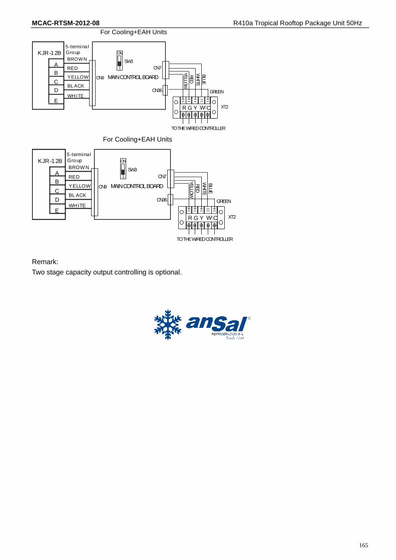
For Cooling+EAH Units
R Y (C)G W
For Heating&cooling Units
R Y (C)G B
Dial code setting
The wired controller KJR-12B can be used when the SW3 is on “on”, if the SW3 is on „1”, the wired cotroller
KJR-23B or KJR-25B can be used. After setting, please shut off the power supply and then power on it again,
otherwise, the new settings function will be invalid.
R Y CG ( )
For Cooling Units
CN9
MAINCONTROLBOARD
SW3
CN7
CN36
GR
EEN
YELLO
W
RED
WH
ITE
XT2
TOTHEWIREDCONTROLLER
ON
1
KJR-1 2B
B
A
C
D
E
BROWN
RED
YELLOW
BL ACK
WHITE
5-termina l
Group
MCAC-RTSM-2012-08 R410a Tropical Rooftop Package Unit 50Hz
165
KJR-1 2B
B
A
C
D
E
BROW N
RED
YELLOW
BL ACK
WHITE
5-termina l
Group
R Y CG ( )W
BLU
E
For Cooling+EAH Units
CN9 MAINCONTROLBOARD
SW3
CN7
CN36 GREEN
YELLO
W
RED
WH
ITE
XT2
TOTHEWIREDCONTROLLER
ON
1
KJR-1 2B
B
A
C
D
E
BROW N
RED
YELLOW
BL ACK
WHITE
5-termina l
Group
R Y CG ( )W
BLU
E
For Cooling+EAH Units
CN9 MAINCONTROLBOARD
SW3
CN7
CN36 GREENYELLO
W
RED
WH
ITE
XT2
TOTHEWIREDCONTROLLER
ON
1
Remark:
Two stage capacity output controlling is optional.