Embed Size (px)
Citation preview

NASA TN -7985 C.1
NASA TECHNICAL NOTE
3 - * i .14
$ 1
COMBINED RADIATION, CONVECTION, A N D CONDUCTION FOR A SYSTEM WITH A PARTIALLY TRANSMITTING WALQ , .
Robert Siegel und Nihud A. Hzcssuin I
I Lewis Research Center i
Cleueiund, Ohio 44135
R . b l J NATIONAL AERONAUTICS A N D SPACE ADMINlS-TR-AftBH WASHINGTON, D. C. 0 !JUN;Ei AB75
https://ntrs.nasa.gov/search.jsp?R=19750017020 2018-05-12T11:48:58+00:00Z

TECH LIBRARY KAFB, NM
7. Author(s) Robert Siegel, Lewis Research Center; and Nihad A. Hussain,
~
San Diego State Univ., San Diego, California 9. Performing Organization Name and Address
I111111 llHl11111Il11 llll Ill# 111ll11111111
8. Performing Organizatioi
E-8150 ~~
10. Work Unit No.
505-04
~- ~~~ 0133542 2. Government Accession No. 3. Recipient’s Catalog No
~ ~~
5. Report Date I June 1975 .- -~
1. Rewr t No. NASA TN D-7(?&5
. .-
4. Title and Subtitle
COMBINED RADIATION, CONVECTION, AND CONDUCTION FOR A SYSTEM WITH A PARTIALLY TRANSMITTING WALL 6. Performing Organizatio I
..
6. Abstract
The net radiation method is developed for sys tems having both opaque and partially ti wal l s . Heat convection is present at the sur faces and heat conduction through the wir taken into account. Specific equations are derived for a window between two paral le l where one plate is a t an elevated temperature typical of what would be encountered i n furnace, and the other plate is being cooled. A two-band model is used with cutoff w typical of g l a s s o r quartz . Numerical r e su l t s a r e obtained for the window temperatu heat flow through the window, The effect on these quantities of var ious plate temper: emissivi t ies is shown.
7. Key Words (Suggested by Author(s))
Thermal radiation Radiation heat t ransfer Radiation through window
18. Distribution Statement
Unclassified - unlimited STAR Category 34 (rev. )
I 21. NO. ;g~ages I 2: I Window heat t ransmiss ion
. . -.
9. Security Classif. (of this report) 20. Security Classif. (of this page)
Unclassified I . ~~~~
Unclassified
* For sale by the Nat ional Techn ica l Information Service, Spr ingf ie ld, V i rg in ia 22151

COMBINED RADIATION, CONVECTION, AND CONDUCTION FOR
A SYSTEM WITH A PARTIALLY TRANSMITTING WALL
by Robert Siege1 a n d Nihad A. H u s s a i n "
Lewis Research Center
SUMMARY
The net radiation method is developed for systems having both opaque and partially
For an opaque wall, a local heat transparent wal l s . conduction through the partially transparent windows. balance is formed by directly using the local incoming and outgoing radiative fluxes. At a window boundary however, the transmitted portions of the energy must not be included in the radiative fluxes contributing to the local energy balance. derived for a window between two parallel plates where one plate is a t an elevated tem- perature typical of what would be encountered in a n electric furnace, and the other plate is being cooled. quartz. opaque regions of the window. ature and the heat flow through the window. plate temperatures and plate emissivities i s shown.
Heat convection is also included at the boundaries as well as heat
Specific equations are
A two-band model is used with cutoff wavelengths typical of glass or There a r e appreciable fractions of radiant energy in both the transparent and
Numerical results a r e obtained for the window temper- The effect on these quantities of various
INTRODUCTION
Two methods have commonly been used in the l i terature to compute radiation heat transfer in enclosures: ray tracing and the net radiation method. method uses the procedures of geometric optics to follow the paths through the system of specific quantities of radiation. In the net radiation method a system of simultaneous equations is derived by utilizing heat balances at the enclosure boundaries. The equa- tions are sufficient to determine all the heat fluxes within the system.
The r ay tracing
* Associate Professor of Mechanical Engineering, San Diego State University, San Diego, California; Summer Faculty Fellow at the Lewis Research Center in 1974.

For devices such as solar collectors and solar s t i l l s r a y tracing is the method that has been used to compute the transmission through the glass cover plates (refs. 1 and 2). The net radiation method has been wel l developed in the l i terature for radiation exchange in enclosures with opaque surfaces (refs. 3 and 4). radiation method provides a convenient technique for computing the radiative behavior of semitransparent layers. Little has been done in the l i terature to apply the net radiation method for systems involving both opaque and partially transmitting w a l l s especially for situations where both convection and conduction a r e also present. especially useful in these instances as the radiative fluxes can be readily combined with the fluxes from other heat transfer modes.
When a radiative component must be included that i s partially transmitted through a When
As shown in reference 5 the net
The procedure i s
wal l , the application of the net radiation method i s unfamiliar to most engineers. conduction and/or convection i s also present a t an interface, the transmitted portion of the radiation must be subtracted as i t does not contribute to the heat flux at that loca- tion. typical of those in furnaces (1000 to 2000 K). t u re s mater ia ls such as glass o r quartz are good t ransmit ters for a portion of the radi- ant energy spectrum, while for the remainder of the spectrum these materials a r e good absorbers (poor transmitters). The purpose of this report is to show how the net radi- ation method can be applied for systems having both opaque and partially transmitting w a l l s with simultaneous convection and conduction, and to give some typical resul ts for an application of interest.
In some metallurgical electric furnaces, a glass o r quartz envelope i s used to con- tain an inert gas or maintain a vacuum around a heated sample. the sample would be surrounded by a radiation shield which i s enclosed in the inert gas o r vacuum envelope. environment o r i s enclosed by a water cooled jacket.
An additional complication is present when the temperatures a r e in the range For radiation emitted a t these tempera-
In a typical geometry
The outside of the envelope is either exposed to the surrounding
Figure 1 shows the typical transmission characterist ics of window glass a s a func- There is a region of high transmission extending ac ross the visible tion of wavelength.
region and portions of the adjacent ultraviolet and infrared regions. In the ultraviolet there is a strong cutoff and a t wavelengths shorter than this cutoff the transmission is very low. energy in the ultraviolet region so the effect of this cutoff can be neglected. of interest he re is in the infrared, and for glass i s typically a t about 2 .8 micrometers (increases to about 4 . 0 pm for quartz). emitted energy i s centered about the infrared cutoff wavelength as shown in figure 1 so that there a r e appreciable fractions of the radiant energy in both the transparent and the opaque regions of the window. There i s a complicated interaction as some of the radiation i s absorbed in the opaque region of the window while other portions a r e trans-
For the thermal conditions that will be discussed here there i s negligible The cutoff
At furnace temperatures, s ay 1500 K, the
2

mitted and reflected between the boundary wal l s . the conduction and convection fluxes, and to reradiation by the window.
solar collector. for a furnace window. source and i s essentially all a t short wavelengths in the transparent region of the glass cover plates. The reemission from the solar absorber is at a much lower temperature (typically 350 K as indicated in fig. 1) and this energy i s all in the region where the win- dow is almost opaque. Hence for the solar collector, with regard to the window proper- t i e s the incident and reemitted energies can be treated separately to a good approxima- tion.
The absorbed portions contribute to
A wel l known application involving heat radiation through windows is the flat plate In this instance the heat transfer interaction i s not as complicated as
The incident solar radiation is from a very high temperature
The results of interest for the furnace design a r e how hot the window w i l l become under the influence of combined radiation, convection, and conduction, to what extent the window ac t s as a shield in seducing heat losses from the furnace, and how effective an adjacent cooled plate is in reducing the window temperature.
ANALYSIS
Although a metallurgical furnace of the type considered here is typically cylindrical, the concentric radiation shield, glass or quartz envelope, and cooled plate can be ap- proximated as parallel plates (fig. 2). gray and each i s isothermal a t i t s respective temperature level. a r e considered to be gas filled (nonabsorbing gas) to make the analysis more general, and the heat transfer coefficients can differ in each of the spaces. Some resul ts w i l l also be given for the spaces evacuated. Because of the low thermal conductivity of the glass o r quartz and because appreciable heat fluxes a r e likely to be transferred, a sig- nificant temperature gradient ac ross the window i s expected; thus one-dimensional con- duction through the glass or quartz envelope i s also included in the analysis.
The shield and the cooled plate a r e assumed The intervening spaces
Radiation Characterist ics of a Single Window by Itself
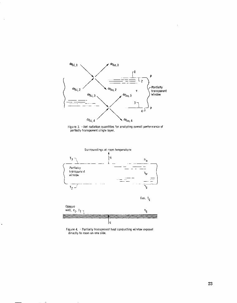
Pr ior to considering a window in a system with opaque w a l l s the window is consid- ered f i r s t by itself. tion process caused by the interaction with the f i r s t and second surfaces of the window. A convenient procedure in the system analysis i s to separate this interaction by first analyzing the window by itself. To obtain the transmission, absorption, and reflection characterist ics of a window for incident radiation by use of the net radiation method, consider a single layer as shown in figure 3. The spectral reflectivity a t each of the
When radiation is incident on a window, there is a multiple reflec-
3

interfaces is pA and the spectral transmittance across the interior of the layer is T ~ .
The relations between the outgoing and incoming energy fluxes a t each interface can be expressed in t e r m s of the reflection at the interface and the transmission a c r o s s the interface. Using the net radiation concepts, the outgoing spectral flux is written for each side of each interface to give (see fig. 3),
dqAo, 1 = PA
q o , 2 = (1 - P A h A i , 1 + PA
@Ao, 3 = PA QAi, 3 + (1 - PA)dqAi, 4
dqAo, 4 = (1 - PjplAi , 3 + PA ds,i) 4
1 + (1 - PA)dqAi, 2
2
The transmittance of the medium is used to relate the internal dqAi's and dqAols,
dqAi, 2 = 'A d q ~ o , 3
dqAi, 3 = dS,o, 2
To obtain the overall reflection and transmission characteristics, it is only neces- sary to consider a unit amount of radiation incident on one side of the window. let dqAi7 = 1 and dqAi,4 = 0. The dqAi,2 and dqAi,3 a r e eliminated by substituting equations (2) into equations (1); the resulting equations a r e solved fo r the dqXols to ob-
Hence,
tain,
- * l - P A - 2 2 A h 1 - p 7
4

For a unit value of dqxi. 1, the fractions reflected and transmitted by the window a r e
The overall spectral absorptance of the glass window is then
A A - - l - R A - T X
Window in System with Opaque Plates
To write the heat balance in the system, the window emittance must be known. Be- cause of the diathermanous nature of the window, the emitted energy leaving one side of the window will to some extent be a mixture of the energy spectrums typical of the local temperatures throughout the window thickness. The concept of emittance for a partially transparent medium i s strictly applicable only for a medium at uniform temperature. A s an engineering approximation this effect can be neglected here for two reasons, and the emittance applied locally a t each window surface. The f i r s t reason is that for the thin windows considered here, the temperature variation throughout the window is small relative to that required to produce a significant spectral shift of the emitted radiation (for a blackbody the wavelength a t peak emission varies as l/T). arises from the fact discussed earlier that window materials such as glass o r quartz have the characteristic of being almost completely transparent in a wavelength range, and are highly absorbing (almost opaque) a t other wavelengths. region the approximation of defining a window emittance i s not significant as relatively little energy is emitted in this wavelength range. In the highly absorbing region there is good emitting ability throughout the window thickness, but the approximation is again valid as little of this energy can penetrate within the window and the emission is chiefly from a region near each window surface. Thus at each surface a window spectral emit- tance can be utilized as obtained from Kirchhoff's law,
The second reason
Thus in the transparent
5

= A = l - % - T A A,w A E (5)
net the
Using the relations in equations (4) and (5) for single window characteristics, the radiation equations can now be written for the enclosure system. opaque surfaces in figure 2 .
Fi r s t consider From the net radiation equations in spectral form, the
outgoing radiant energy is written in t e r m s of the emitted and reflected portions as
- dqXo, 1 - ‘leAb, 1 dA + (l - ‘lIdqXi, 1
The heat balance at each of the opaque surfaces involves the heat transfer to the adjacent gas. the radiative fluxes a r e integrated over all X to form a balance with the convective energy. This yields
This is a total energy quantity, that is, it involves energy at all wavelengths, so
/-m
r m
The q is the total heat transfer ac ross the system; it i s the external energy supplied a t surface 1 and removed from surface 4.
The net radiation equations a r e now considered for each surface of the window. By use of the overall coefficients for the window, the equations for the outgoing fluxes, in- cluding the reflected and transmitted components, a r e
- dqXo, 3 - ‘A, weXb, 3 + % dqXi, 3 + TA dqAi , 2
6
I

Consider a heat balance including the radiative fluxes, the convection and the con- duction at each surface of the window. To obtain the interaction with conduction and convection, it is necessary to consider total heat balances, that is, balances that in- clude energy a t all wavelengths. ing that the radiation components transmitted through the window will not contribute to the local energy balance. Hence the conservation of energy a t each of the two window surfaces results in
For this energy balance c a r e must be taken in realiz-
Across the gaps between the window and the opaque wa l l s there are the relations for the radiative terms,
The convective heat transfer in the gaps when they are gas filled. gives the following re- lations:
Hence from equations (11)
T = Tl + T2 g 2
and

T3 -I- T4 Ta = 2
(12b)
It is desired to obtain relations for the heat flow q, and the temperatures T2 and T3 on both sides of the window. To begin the solution, equations (12) a r e used to elim- inate T the dqAi from equations (6) to (9). The result is then the following system of equa-
and Ta from equations (7) and (9), and equations (10) are used to eliminate g
Now use equation (13) to eliminate cis,,, and dqAo, from equations (14), (15), and (16). Also add equations (14a) and (14b) and divide by 2 to obtain a symmetric form. This yields
8

ha h
4 4 + (TI - T2) + - (T3 - T4)
Equations (17a) and (17b) are solved simultaneously for dqho, and dqho, to yield
These relations a r e substituted into equations (18), (19a), and (19b) to give
9

11111111.1 1.11 I.-. ,111. I. 1.1 - ,.,, , ....-__
(Ah,-4leAb, 1 - 14eAb, 4) + 'BA, 14eAb, 2 - BA, 41eAb, 3) dA
2DA, 14
ha h
4 4 + 4 (T1 - T2) + - (T3 - T4)
1 cEh, 1 4 e ~ b , 1 + F ~ , 1 4 e ~ b , 2 + G ~ , 1 4 e ~ b , 3 + H ~ , 1 4 e ~ b , ,Idh
h
W 2 = 5 (T2 - T3) - 3 (T1 - T2) ( 2 2 4
1 [HA, 41eAb, 1 i- GA, 41eAb, 2 + FA, 41eAb, 3 + E A , 41eAb, 41dh
10

The temperature of each surface of the window, T2 and T3 is found from the simul- taneous solution of equations (22a) and (22b), and q can then be evaluated from equa- tion (21). Some typical resul ts wi l l be obtained by means of a two-band calculation.
Relations for Two-Band Calculation
A s shown in figure 1, glass or quartz has a well-defined cutoff wavelength X c in the infrared region a t which the transmittance as a function of wavelength changes from a high value to a low value. In view of the shape of the typical transmittance curve in figure 1, a reasonable approximation that wi l l be used for the present problem is that the transmittance is a constant on either side of Xc. As mentioned before, for g l a s s there is also a region of very low transmission in the ultraviolet region, but there is negligible energy in this range in the radiation spectrum of the present problem which is concerned with furnace temperatures. For a surface a t temperature Tn let the f rac-
radiation in the short wavelength range 0 5 X 5 hc be designed by tion of blackbody FXcTn’ that is
The FA is a
(ref. 6) e n
function only of ACTn and is given to a very good approximation by
n1=1,2, . . .
= I - - 1 5 v 3 1 - v - + - - - v2 v + V ) v < 2 6
V 4
4 (; 8 60 5040 272 160 13 305 600 FhcTn 77
4 where v = 1.4388XlO /ACTn and ACTn is in (pm)(K). can be written as
Then equations (22a) and (22b)
11

CY 2 {[E:, 14D:, 14'AcT1 DE, 14DA, 14 +EA,14 ' DS A,14 (1 -'AcT1)]T:
2 DS (1 - F~ ,IT; + 'A, 14 A, 14 14DA, 14'hcT2 c 2
2 14DA, 14'AcT3 G;f, 14D!, 14(1 -
DS (1 - FA T IT:} c 4 + b:, 14DA, 14FkcT4 + HA, 14 A , 14 1
' DS (1 - FAcTJ]T/: (b:, 41Di, 14'AcT1 i-HA,41 A,14
U
2 Df, 14DA, 14
41DA, 2 14'ACT2 + GA, ' 41 DS A, 14 (1 - FAcT2)]Ti
+ [ ' 'A,41 D2 A , 14FAcT3 'A, ' 41 DS A, 14 (1 - FAcT3)]T:
+ [.?, 41D:, 14FAcT4 EA, ' 41 DS A, 14(1 - FAcT4]Ti}
It is necessary to solve equations (23a) and (23b) by simultaneous iteration because and T3 is in FA . Once T2 and T3 a r e evaluated,
c 2 c 3 T2 is in the function FA
then q can be determined from equation (21) as
12

14
DA, 14
+A (1 - FA 3 2 4 1
Some resu l t s for specified conditions wi l l be evaluated a little later.
simplified case. A s w a s previously discussed, for wavelengths smaller than the cutoff wavelength, g lass o r quartz is typically quite transparent (neglecting the ultraviolet r e - gion), while fo r wavelengths longer than the cutoff, the window becomes almost opaque. For the simplified case i t is assumed that the window is perfectly transparent for 0 I X 5 Xc and perfectly opaque for the remainder of the wavelength region. simplified case the surface reflectivities of the window a r e set equal to zero. on these assumptions, equations (23) and (24) reduce to the following:
Because of the complexity of equations (23) and (24) it is worthwhile to examine a
For the Based
(25b) )Ti] = > (T3 - T4) - - % (T2 - T3) "4[(l - - (1 - W
(26) %v T + - (T2 - T3) - + - - 1 @ACTl Tt - FXcT4 :) W
0 - - gapproximate
where equations (25a) and (25b) were used to reduce the last t e rm on the right side of equation (26) to the form given.
unknown temperatures T2 and T3, the solution is much simpler than dealing with equations (23a) and (23b). the radiant exchange that occurs as a result of the portion of emitted energy from each
Although equations (25a) and (25b) must be solved by simultaneous iteration for the
The first t e rm in the approximate heat flux equation (26) is
13
opaque wall that is in the wavelength region for which the window is completely trans- parent ( A < Ac). The second te rm accounts for all the other energy that is transferred; th i s is by radiation in the region where the window is opaque and by convection. This energy must pass through the window by conduction thus giving the form shown for the second term. The values of the temperatures T2 and T3 in this te rm are obtained from equations (25a) and (25b) which involve the radiation in the opaque region (A > X c ) and the convection.
Although equations (25) and (26) can be placed in dimensionless form, there are so many independent groups even for these simplified equations that the dimensionless form is not especially advantageous unless very extensive se t s of resul ts are to be presented. To aid in the physical interpretation, the typical resul ts presented here will be given in dimensional form.
glass o r quartz window is exposed directly to the room, that is, there is no outer cool- ing jacket. The present solution can be directly applied since the surroundings can be represented as a blackbody a t the room temperature. Hence for this case let c 4 = 1 and T4 be equal to the room temperature. the convective coefficient for the outside of the window exposed to the room environment. If there i s sufficient vacuum in the gap to eliminate convection and conduction between the hot surface and the window, let h = 0.
Another configuration of interest in addition to figure 2 is where the outside of the
This is shown in figure 4.
The ha is
g
RESULTS AND DISCUSSION
As indicated by the limiting equations (25) and (26), there are several parameters in the present problem; for the actual situation in figure 2 there a r e even more param- e t e r s than in the limiting case. The parameters involve the wal l emissivities, absorp- tion coefficient of the glass, heat transfer coefficients in the gaps, thermal conductivity of the window, the cutoff wavelength, and so forth. It is not feasible to give resul ts for all the ranges of variables that can be encountered. The main purpose of the present report is to demonstrate how the net radiation method can be applied to this type of sys- tem. compared with those from the approximate solution.
are both 1. 0 centimeters (0. 394 in. ) and the glass thickness w is 0. 635 centimeter (0.25 in. ). cients ha and h a few cases where the gaps were evacuated so that ha = h = 0. In the range of temper-
g a tu res expected in furnaces, silica glass had a thermal conductivity approximately equal to 0.05 W/(cm)(K) as given in reference 7 .
Hence only some typical numerical resul ts will be given; the resul ts wi l l also be
All the resul ts that follow are for a fixed geometry. The gap spacings a and g
The thermal conductivity of the window Q, and the heat transfer coeffi- in the gaps were kept constant throughout the calculations except for R
14

To obtain ha and h the Rayleigh number between the window and opaque wal l s w a s calculated assuming nitrogen filled gaps a t atmospheric pressure, a gap width of 1 .0 centimeter, and temperature levels (typically 1000 K) and differences (a few hun- dred degrees K) typical of furnace operation. The Rayleigh number based on the gap
3 3 width w a s generally 10 or less, and for only a few cases became as high as 4x10 . The Rayleigh number for the onset of f r ee convection in a vertical enclosed gap is about
3 3 10 (ref. 8), and for a Rayleigh number of 4x10 the conduction heat transfer is only en- hanced about 25 percent by the convective effect. Thus for the present conditions the heat transfer is essentially all by heat conduction. The heat transfer coefficient used here is based on the temperature difference from a surface to the average gas tempera- ture. For only heat conduction, with a constant thermal conductivity, the average tem- perature would be a t the midpoint of the gap. Hence the convective heat t ransfer coef- ficient is replaced in the pure conduction case by h = k/(g/2) and ha = k/(a/2) (the factor of 1/2 a r i s e s f rom the h in eq. (11) being based on the temperature difference relative to the average gas temperature in the gap). Based on typical average nitrogen temperatures of 1400 and 900 K in the gaps, the values were obtained as h = 16.9 W/(m )(a and ha = 12.6 W/(m )(K). not changing too many variables, these values were retained throughout the calculations except when the gaps were evacuated so that h = h = 0.
from equation (4), the ph and T~ a r e needed. To evaluate %, Th, and E
The ph w a s found from Snell's law using an index of refraction n = 1.5 and an inci- dence angle of 58' which w a s found in reference 9 to give good results for diffuse inci-
dent radiation. where L is the path length in the window for incidence a t 58'. The window thickness w w a s taken as 0.635 centimeter (0. 25 in. ). From reference 10 using ah = 0 .2 centimeter-' gave 7X = 0. 857 for h < hc, and using ah = 5.7 centimeter-' gave T~ = 0.0125 for X > hc where hc = 2. 8 micrometers which i s typical for many types of g lass (quartz has a higher cut- off wavelength 3 4 pm). comparable to those in ref- erence 11. quartz as well as for g lass with the exception of the cutoff wavelength which is 2. 8 mi- c rometers for g lass and 4.0 micrometers for quartz.
a tures and emissivities of the opaque walls . tions (23) and (24) wi l l be given, and the resu l t s wi l l a l so be compared with those from the approximate solution in equations (25) and (26).
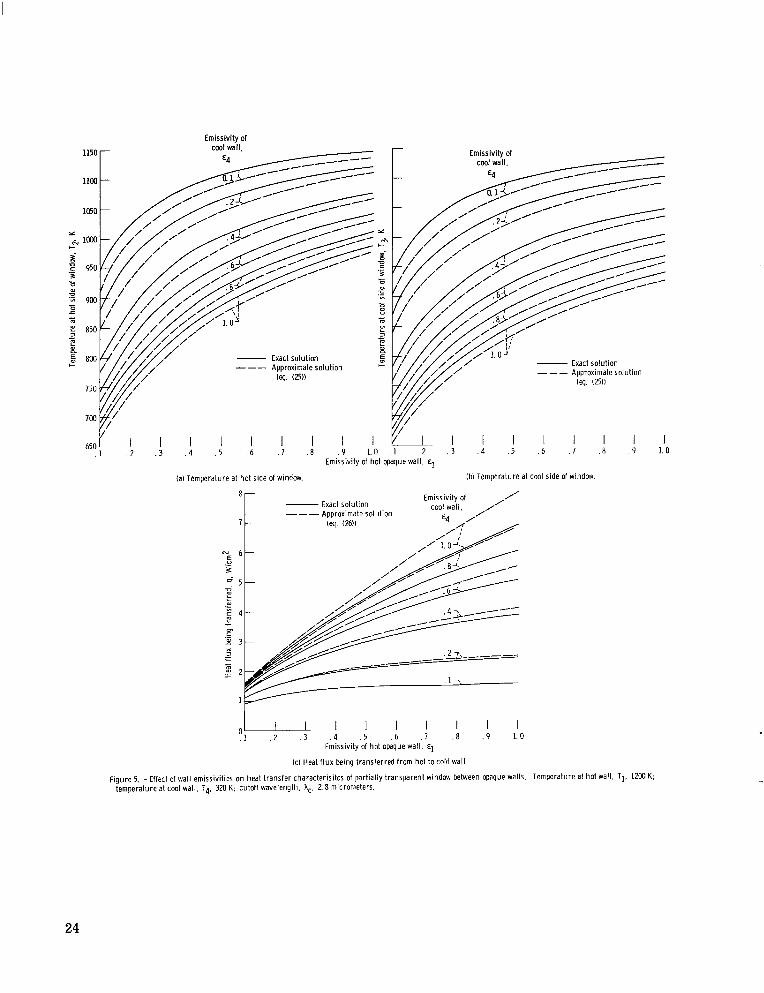
T4 = 320 K which i s typical of cooling by nonpressurized water. is representative of that for glass, hc = 2. 8 micrometers . temperatures on the hot and cool sides of the window, while figure 5(c) gives the heat
g '
g
2 2 g To simplify the interpretation of the resu l t s by
g a A, w
-ahL This gave ph = 0.080 for all A . The T~ = e
These values give resu l t s for E W
These conditions wi l l be held constant, and they also apply quite well for
I The principal quantities that w i l l be varied in the figures that follow a r e the temper- Some typical numerical resu l t s f rom equa-
L
In figure 5 the temperature T1 of the hot wa l l is 1200 K and the cooled wa l l is at The cutoff wavelength
Figures 5(a) and (b) give the
15

t ransfer red from the hot to the cold wall by the combined modes of radiation, convec- tion, and conduction. The resu l t s a r e plotted as a function of the emissivity of the hot wal l with the different curves corresponding to various emissivities of the cooled wall. Two sets of curves a r e shown: the solid lines correspond to the complete solution (eqs. (23) and (24)), while the dashed lines a r e for the simplified approximate solution (eqs. (25) and (26)).
pera tures since increasing e l wi l l increase the heat transfer t o the window while in- creasing e4 wi l l increase the heat t ransfer away from the window and to the cooled wall. Thus the lowest window temperatures wi l l be obtained when e l is low and c4 is high. losses a r e substantially diminished by reducing at least one of the wall emissivities. have both a low window temperature and a small heat loss it is the e l that should be kept small. It may be possible to do this only to some extent if the hot surface is a '
nietal because the emissivity increases a t the high temperatures characteristic of fur - nace operation.
tion, the values being within about 3 percent of the exact equations. f igure 5(c) is also in reasonable agreement with the exact solution; the largest deviation is when both e l and c 4 are large and then the difference increases to about 15 per- cent. The approximate solution is probably adequate for most design purposes.
In figure 6 the effect is shown of letting the temperature of the cooler wal l be at a higher temperature than in figure 5. but resu l t s in an increased window temperature as shown by figure 6(a). gives the temperatures on the two sides of the window; the temperature difference ac ross the window ranges from about 10 to 25 K. tion (26) to obtain an approximate idea of the amount of heat being transferred by means other than by direct transmission in the transparent region of the window.
the hot surface; the conditions a r e the same as for figure 5 except that the hot wal l tem- perature is increased from 1200 to 2000 K. temperatures which of course a r e higher than those in figure 5. t ransferred is shown in figure 7(b), and comparisons a r e made in figures 7(b) and (c) with the approximate solution in equations (25) and (26). At these higher temperatures the approximate solution has significant deviations from the exact solution for many con- ditions and is somewhat inadequate for window temperature predictions. window temperatures shown are above the melting point for glass. a guide as to what conditions a r e necessary to avoid melting of the window.
Figure 8 shows the effect of taking the situation in figure 5 and removing the gap con- duction and/or convection heat transfer. Conduction and/or convection provides a means
The emissivities of the hot and cool wa l l s have opposing effects on the window tem-
The largest heat losses correspond to both e l and e4 being large. The To
The temperatures in figure 5 a r e predicted quite well f rom the approximate solu- The heat flux in
This reduces the heat loss as shown by figure 6(c) Figure 6(b)
This difference can be used in equa-
The purpose of figure 7 is to illustrate the effect of increasing the temperature of
Figure 7(a) shows the resulting window The heat flux being
Some of the The resu l t s provide
16

of heat transfer parallel to the radiative heat t ransfer and hence as shown in figure 8(b) the heat transfer is reduced when the gaps a r e evacuated. The window temperature is generally increased when ha = h = 0 but there a r e some conditions where the window temperature is decreased. To explain this behavior it is realized that heat is t rans- f e r r ed both to and from the window by conduction and/or convection. When these two portions a r e equal, the average window temperature T (neglecting the fact that the two surfaces of the window are somewhat different in temperature) would be given by
g
w, avg
= 824 K. Thus if the window temper- w, avg Inserting the conditions of figure 8(a) yields T a ture as shown by the solid line is greater than about 824 K, the window is losing more heat by convection than it is gaining; hence, in this instance removing the convection (dashed lines) causes the window temperature to be increased. If, on the other hand, the window as shown by the solid line is below about 824 K, the convection is providing a net heat gain by the window; letting the convection be ze ro then causes a reduction in window temperature. This accounts for the crossing of the dashed and solid curves in figure 8(a). When T1 was raised to 2000 K, the radiative t e r m s increase substantially in comparison with the convection terms. a ture level, the convection has a minor influence and the dashed and solid curves a r e practically the same in this instance.
has a cutoff of about 4 micrometers which is somewhat la rger than that for g lass which is at about 2. 8 micrometers . length from 2. 8 to 4.0 micrometers on the window hot side temperature and on the heat flux being transferred. Increasing the cutoff causes a grea te r fraction of the energy to be in the transparent region of the window. For a blackbody surface emitting a t 1200 K, the fraction of the energy in the transparent region of the g lass is FACT = F(2. 8)(1200) = 0. 35 while for quartz this increases to F(4. o)(1200) = 0.61. This
shift reduces energy absorption for the quartz window and reduces the window tempera- ture. The increased region of transparency a l so reduces the effectiveness of the window as a radiation shield, and the heat being t ransferred is therefore increased.
The calculations showed that, at this temper-
The cutoff wavelength can vary with the type of optical mater ia l being used. Quartz
Figure 9 shows the effect of increasing the cutoff wave-
CONCLUSIONS
An analysis has been developed to show how the net radiation method can be applied for systems involving both opaque and partially transparent walls. cludes conduction and/or convection heat transfer in the g a s adjacent t o the walls, and
The analysis in-
17

heat conduction through partially transparent windows. For opaque walls the net radia- tive fluxes are used directly in forming local heat balances. For a window, however, care must be taken in the heat balance a t a window boundary to include only the portions of the radiative t e r m s that interact locally with the convection and conduction. transmitted portion of the radiation is subtracted from the net radiative fluxes that would be used if the wall were opaque.
plate being at much higher temperature than the other. range typical of electric furnaces. divided between the wavelength regions below and above the cutoff wavelength of the window. the remaining radiation is in a region where the window is practically opaque.
The effect on the window temperature and the amount of heat t ransferred is demon- strated for various wall temperatures and plate emissivities, with and without gas in the gaps on both sides of the window, and for the cutoff wavelengths typical of glass and quartz. duce the emissivity of the hot surface. g l a s s which means that relative to glass there is greater transmitted and less absorbed energy. heat loss wi l l be increased and the window temperature reduced.
The
Specific resul ts are obtained for a window between two opaque parallel plates, one The high temperature w a s in a
At this level the radiative energy is fairly equally
Thus a portion of the radiation passes quite readily through the window while
To reduce both window temperature and heat loss, i t is most desirable to r e - The quartz has a higher cutoff wavelength than
Thus for all other characterist ics being the same, when quartz is used, the
Lewis Research Center, National Aeronautics and Space Admini stsation,
Cleveland, Ohio, February 21, 1975, 505-04.
18

APPENDM - SYMBOLS
ah
dqx
eXb
h
k
L
n
W
E
Subscripts:
a
W
h
overall spectral absorptance, reflectance, and transmittance of window
spectral coefficients in derived equations
s p e c t r a absorption coefficient
differential heat f lux in wavelength interval dA
blackbody spectral emissive power
fraction of blackbody radiation in range 0 - AT
heat t ransfer coefficient
thermal conductivity
path length within window
index of refraction
total heat flux being t ransferred
convection (or conduction) in gas filled gaps
absolute temperature
thickness of window
emissivity
spectral emissivity, reflectivity, and transmittance
wavelength
cutoff wavelength
Stefan - Boltzmann constant
gap between window and cool wal l
average
gap between hot wa l l and window
incoming
outgoing
window
spec t r a1 quantity
13

1,2 , 3 , 4 hot wall, hot side of window, cool side of window, cool wall; o r lst, 2nd, 3rd, and 4th interfaces for single layer
Superscripts:
1 , s long and short wavelength radiation
20

REFERENCES
1. Hottel, H. C. ; and Woertz, B. B. : The Performance of Flat-plate Solar-heat Col- lectors. ASME Trans, vol. 64, no. 2, Feb. 1942, pp. 91-104.
2. Whillier, A. : Solar Energy Collection and its Utilization for Home Heating. Sc. D. Thesis, Dept. bf Mech. Eng. , Massachusetts Institute of Technology, 1953.
3. Siegel, Robere and Howell, John R. : Thermal Radiation Heat Transfer. McGraw
4. Sparrow, E. M. ; and Cess, R. D.: Radiation Heat Transfer.
Hill, 1972.
Brooks/Cole Publ. Co., 1966.
5. Siegel, Robert: Net Radiation Method for Transmission Through Partially Trans- parent Plates. Solar Energy, vol. 15, no. 3, Sept. 1973, pp. 273-276.
6. Wiebelt, John A. : Engineering Radiation Heat Transfer. Holt, Rinehart and Win- ston, Inc. , 1966.
7. Touloukian, Y. S. ; Powell, R. W.; Ho, C . Y.; and Klemens, P. G. : Thermal Conductivity of Non-Metallic Solids. Vol. 2, Thermophysical Propert ies Research Center Data Series, Purdue University, 1970.
8. Eckert, Ernst R. G. ; and Drake, Robert M. , Jr. : Analysis of Heat and Mass Transfer. McGraw-Hill, Inc. , 1972.
9. Hottel, Hoyt C. ; and Whillier, Austin: Evaluation of Flat-Plate Solar-Collector Performance. Trans. of Conference on U s e of Solar Energy. The kient i f ic Basis, Volume 2 - Thermal Processes, Sec. A, Tucson, Arizona, 0c t . 31 - NOV. 1, 1955, pp. 74-105.
10. Gardon, Robert: A Review of Radiant Heat Transfer in Glass. J . h e r . Ceramic Society, vol. 44, no. 7, July 1961, pp. 305-312.
11. Gardon, Robert: The Emissivity of Transparent Materials. J. Amer. Ceramic Society, vol. 39, no. 8, Aug. 1956, pp. 278-287.
21

1. (
, E U c .- 5 2 E F .6
z v) . 4
m L + - c U al n
rrJ
E L 0 z
-
. 2
0
-
,-Typical normal spectral transmittance - ‘ curve for 0.6-cm-thick window glass
-4 95 Percent of radiat ion +from b l body at 1500 K
- I 95 Percent of solar radiation- +(blackbody at 5780 K) I
-Ultraviolet cutoff wavelength A 2 0. 27 pm
Visible l ight
In f rared I Ult ra- * !- -; 7
95 Percent of radiat ion +from blackbody at 350 K 4
r l n f ra red cutoff ,I’ wavelength
hC 2.8 pm
I I 1 I I
I I I - I
4 6 8 1 0 20 40 60 )violet I I LI-: I
. 4 . 6 . 8 1 2 Wavelength, A, pm
Figure 1. -Typical spectral t ransmiss ion characterist ics of window glass showing regions of h igh and low transmittance.
Opaque cooled
P dqAi, 3 dqAo, 3 Gas, Ta
_ _ _
c ~ --
Partial ly transparent window---”
“Opaque heated wall lq
Figure 2 - Part ial ly transparent heat conducting window between opaque plates (T1 > T4).
22
/ \
rl P
@Ao, 2 t ranwaren t
F igure 3. - N e t radiation quanti t ies for analyzing overall performance of part ial ly transparent single layer.
Su r round ings at room temperature 4
Opaque wall. €1, TI-!
Gas, Tq
hg
F igure 4 - Part ial ly transparent heat conducting window exposed d i rect ly to room on one side.
23
Emissivitv of
1150 -
1 1 w -
- Exact solution - Exact solution
Approximate solution _ _ _ teq. 12511
I I I I I I I . I . 2 . 3 . 4 .5 . 6 .7 .8 . 9 1.0 . 1 .2 . 3 . 4 . 5 . 6 ,7 . 8 . 9 1.0
Emissivity of hot opaque wall,
(a) Temperature at hot side of window. (b) Temperature at cool side of w i n d w .
Emissivity of /’ ict solution cool wall. //
4 // . ’ ‘ so lu t i on
0 ‘ I l l I I I I . I .2 . 3 . 4 . 5 . 6 . 7 .8 . 9 1.0
Emissivity of hot opaque wall, E]
(c l Heat f l ux being transferred from hot to cold wall.
Figure 5. - Effect of wall emissivities on heat t ransfer characterisitcs of partially transparent window between opaque walls. Temperature at hot wall, TI, 12W K; temperature at cool wall, Tq. 320 K: cutoff wavelength. A,. 2.8 micrometers.
24

Emissivity d lmr cool wall.
12M) 1
_c__-----
1150 -
Temperature at cool wall.
74. K
320 800
- ---
(a) Temperature at hot side of window for temperature at cool wall Tq of 320 and 800 K.
Emissivity of coo) wall.
E4
0.1 7, 1150-
Temperature at hot side
Temperature at c w l side of window. T2
of window. T3
- --_
I TemDerature at &I waii,
T4. K
.1 . 2 . 3 . 4 . 5 , 6 . 7 . 8 . 9 1 . 0 0 1 . 2 . 3 . 4 .5 . 6 , 7 , 8 .9 1.0 Emissivity of hot opaque wall,
(bl Surface temperatures of window for temperature at cool wal l Tq of 800 K (as compared w i th figs. 5(a) and (bl where T4 = 3M K1.
IC) Heat f l ux being transferred from hot to cold wall.
Figure 6. - Effect of increasing temperature of cool wail on heat t ransfer characterisitcs of partially transparent window between opaque walls. Temperature at hot wall, TI, 12w K: cutoff wavelength. hc. 2 8 micrometers.
25

II II I I II 111111.1 1111.1 I1111 I I II II 111111 I1 I I I1 I 1 1111 .11111 I I , . I I , . I...., ...-..... .... -
m r Emissivity of
CMI wall.
1w -
Temperature at hot side of window. T2 Temperature at cool side of window. T3
-~ -_-
- Emissivity of ,
cwI wall. / - Exact solution --- Approximate solution
- iq. 12611 €4 A/
. I . ? . 3 . 4 .5 . b . l , 8 . 9 1.0 I . 2 . 3 . 4 .5 .6 . 7 , 8 , 9 1.0 Emissivity of hot opaque wall,
la) Surface temperatures of window. Ib) Heat f lux being transferred from hot tocold wall.
Emissivity of coo; wall.
Figure 7. - Heat transfer charactel
(c) Comparison of exact and approxlmale solutioils for temperature at hot side of window.
.istics for temperature at hot wall T1 increased to 2wo K. Temperature at cool wall, T4. 320 K; cutof f wavelength. A,. 2 8 micrometers.
26

1150
1100
1050
loo0 & I-
d 2 950 .- 3 c 0 m 5 900 L 0 8 - m E 850 3 m L m Y
800 I-
750
700
650 j!
N
\ E, 5
m
n ._ m
6 - Emissivity of cool wall,
€4
{ 1. 0 5 -
/" 4-
3 -
N 4

h3 to
lmr
Emissivity of cool wall,
E4 1150b 1.0 3,
650 .1 . 2 . 3 . 4 . 5 . 6 . 7 .8 .9 1.0 .1 . 2 . 3 . 4 .5 .6 .7 .8 .9 1.0
Emissivity of hot opaque wall,
(a) Temperature at hot side of window. (b) Heat f l u x being transferred from hot to cold wall.
Figure 9. - Effect of cutoff wavelength on heat transfer characteristics. Temperature a t hot wall, T1, 1200 K; temperature at cool wall, Ta, 320 K.

_-
NATIONAL AERONAUTICS AND SPACE ADMINISTRATION WASHINGTON. D.C. 20546
~.
BOOK
5813 O C i l C 1 U D 750530 SC0903DS D E P T OF THE A I R FORCE AF WEAPDNS L A R O F A r O E Y ATTN: T S C H N I C P L L I B b A R Y ( S U L ) K I 9 T L R N D AFB W M 87117
POSTAGE A N D FEES P A I D N A T I O N A L AERONAUTICS A N D
SPACE A D M I N I S T R A T I O N 451
: If Undeliverable (Section 158 Postal Mnnuol) Do Not Return
“The aeronautical and space activities of the United States shall be conducted so as to contribute . . . to the expansion of human knowl- edge of phenomena in the atmosphere and space. T h e Administration shall provide for the widest practicable and appropriate disseminution o f information concerning its activities and the results thereof.”
-NATIONAL AERONAUTICS AND SPACE ACT OF 1958
NASA SCIENTIFIC AND TECHNICAL PUBLICATIONS TECHNICAL REPORTS: Scientific and technical information considered important, complete, and a lasting contribution to existing knowledge.
TECHNICAL NOTES: Information less broad in scope but nevertheless of importance as a contribution to existing knowledge.
TECHNICAL MEMORANDUMS: Information receiving limited distribution because of preliminary data, security classifica-
TECHNICAL TRANSLATIONS: Information published in a foreign language considered to merit NASA distribution in English.
SPECIAL PUBLICATIONS: Information derived from or of value to NASA activities. Publications include final reports of major projects, monographs, data compilations, handbooks, sourcebooks, and special bibliographies.
TECHNOLOGY UTILIZATION PUBLICATIONS: Information on technology used by NASA that may be of mrticular
tion, or other reasons. Also includes conference proceedings with either limited or unlimited distribution.
CONTRACTOR REPORTS: Scientific and technical information generated under a NASA contract or grant and considered an important contribution to existing knowledge.
interest in commercial and other- non-aerospace applications. Publications include Tech Briefs, Technology Utilization Reports and Technology Surveys.
Details on the availability of these publications may be obtained from:
SCIENTIFIC AND TECHNICAL INFORMATION OFFICE
N A T I O N A L A E R O N A U T I C S A N D SPACE A D M I N I S T R A T I O N Washington, D.C. 20546