Embed Size (px)
Citation preview
MEH637a
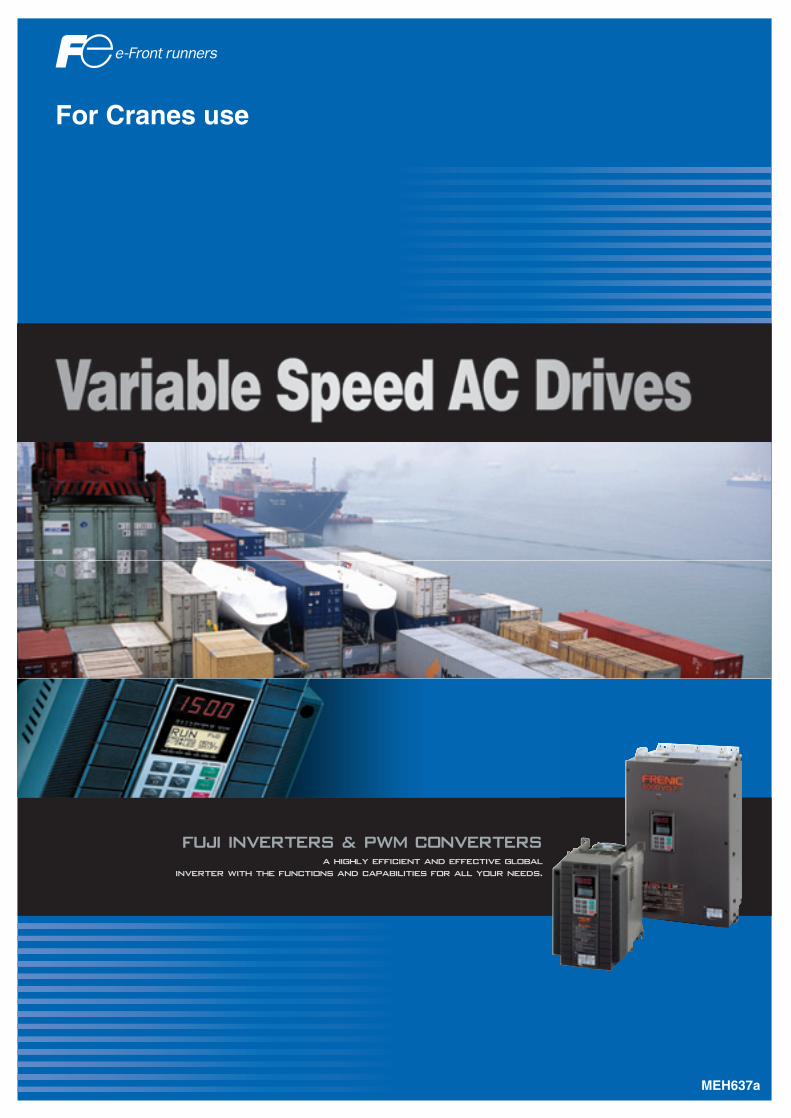
For Cranes use
� ������ ������ �� ������ ������
�������� ���� ��� ������� �� ����������� �� ��� ���� ��� ��
2
A HIGHLY EFFICIENT AND EFFECTIVE GLOBALINVERTER WITH THE FUNCTIONS AND CAPABILITIES FOR ALL YOUR NEEDS.
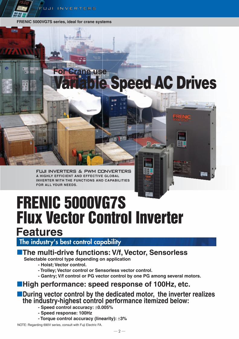
FRENIC 5000VG7S Flux Vector Control Inverter
���� ������ � �� �������
FRENIC 5000VG7S series, ideal for crane systems
The multi-drive functions: V/f, Vector, SensorlessSelectable control type depending on application
- Hoist; Vector control.- Trolley; Vector control or Sensorless vector control.- Gantry; V/f control or PG vector control by one PG among several motors.
- Speed control accuracy: ±0.005%- Speed response: 100Hz- Torque control accuracy (linearity): ±3%
High performance: speed response of 100Hz, etc.During vector control by the dedicated motor, the inverter realizes the industry-highest control performance itemized below:
The industry's best control capability
Variable Speed AC DrivesFor Crane use
-4(05 ����� �� 6*#% �� �" ������ � � 7�8 0��� � 79
Features
3
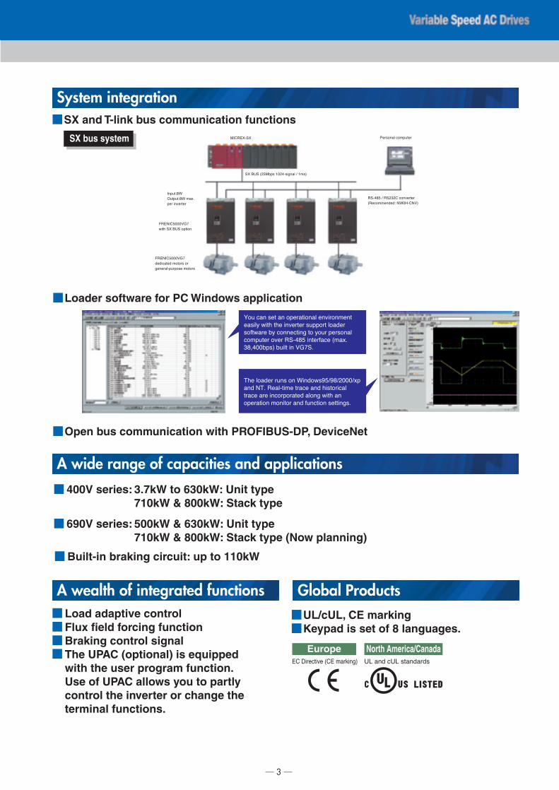
SX and T-link bus communication functions
Loader software for PC Windows application
SX bus system
��� ��� � �� ���� ���� �� �����
�� �� � � � ���� ������ �����
������ �� ����� �� � ���� �������
������ ��� ������ ����� ����
!�"�##���$ �� � � %&'�
(� ����� ���� �� ) �����*�+*�+,###+��
��� -( ���� � ��� ��� � ��� ���
��� �� ��������� ����� � � ��
���� �� ��� �� ��� ���� �� � ���
System integration
Open bus communication with PROFIBUS-DP, DeviceNet
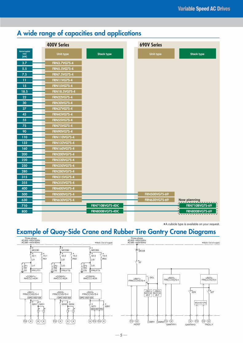
A wide range of capacities and applications
A wealth of integrated functions
3.7kW to 630kW: Unit type710kW & 800kW: Stack type
400V series:
500kW & 630kW: Unit type710kW & 800kW: Stack type (Now planning)
690V series:
Built-in braking circuit: up to 110kW
Load adaptive controlFlux field forcing functionBraking control signalThe UPAC (optional) is equipped with the user program function. Use of UPAC allows you to partly control the inverter or change the terminal functions.
Global ProductsUL/cUL, CE markingKeypad is set of 8 languages.
North America/Canada./ ��� �./ ��������
Europe01 2 �� � �10 ���3 ��$
:;1�0<��<
�< =.� �,�:��� >#,��� ���� + >��$
?������ ������
������ + ��,!,1 ������
���������5 -)#@�1-%$
;���5�)
4���5�) ���
�� ����
7�0-;1�###%&'
� � �< =.� �� ��
7�0-;1�###%&'
�� ��� ����� ��
������������ �����

4
Specifications
400V Series (Unit type)400
400
563
740
1110
704
360
500
500
731
960
1440
880
0.75 to 5
525
630
630
891
1170
1755
1104
525
3.7
3.7
6.8
9.0
13.5
3-phase 380 to 480V, 50Hz/60Hz
Voltage: +10 to -15%, Frequency: +5 to -5%, Voltage unbalance: 2% or less (*2)
7.1
14.9
0.75 to 15
8
Up to 15kW: IP20, 18.5kW or over: IP00 (IP20: option)
5.5
5.5
10
13.5
20.0
10
21.5
8
7.5
7.5
14
18.5
27.5
13.5
27.9
8
11
11
18
24.5
36.5
19.8
39.1
12.5
15
15
24
32.0
48.0
26.8
50.3
12.5
18.5
18.5
29
39.0
58.5
33.2
59.9
25
22
22
34
45.0
67.5
39.3
69.3
25
30
30
45
60.0
90.0
54
86
30
37
37
57
75.0
113
67
104
35
45
45
69
91.0
137
81
124
40
55
55
85
112
168
100
150
41
75
75
114
150
225
134
0.75 to 10
50
90
90
134
176
264
160
72
110
110
160
210
315
196
72
132
132
192
253
360
232
100
160
160
231
304
456
282
100
200
200
287
377
566
352
140
220
220
316
415
623
385
140
315
315
445
585
878
552
250
250
250
356
468
702
438
150
280
280
396
520
780
491
250
355
355
495
650
975
624
300
Type FRN□□□VG7S-4
Nominal applied motor [kW]
Rated capacity [kVA] (*1)
Rated current [A]
Braking method/braking torque
Conditions
Carrier frequency [kHz] (*5)
Mass [kg]
Enclosure
Input
ratings
Phase, Voltage, Frequency (*1)
Voltage/frequency variation
Momentary voltage dip capability (*3)
Rated current [A] (*6)
Required power supply capacity [kVA] (*4)
When voltage drops from the rated voltage, the inverter will continue operation if the voltage is more than 310V.If the voltage is less than 310V, the inverter can be operated for 15ms.
Braking resistor discharge control: 150% braking torque, Separately installed braking resistor (option), Separately installed braking unit (option for 132kW or more)
Indoor use only. Free from corrosive and flammable gases, dusts, and direct sunlight.-10 to +50℃ 5 to 95%RH (no condensing) 3000m or less, with some power derating from 1,001 to 3,000m. Amplitude: 3mm at 2 to 9Hz, 9.8mm/s2 at 9 to 20Hz. 2m/s2 at 20 to 55Hz (2m/s2 at 9 to 55Hz for 90kW or over), 1m/s2 at 55 to 200Hz -25 to +55℃ 5 to 95%RH
5.0 7.0 9.4 14 19 24 28 38 47 57 70 93 111 136 161 196 244 267 304 341 383 432 488 610 765
*1) Inverter output capacity [kVA] at 440V.*2) Use a DC REACTOR if the voltage unbalance exceeds 2% (this is the same as for FUJI's conventional models).Voltage unbalance [%] = (Max. voltage [V] - Min. voltage [V])/Three-phase average voltage [V] X 67*3) Tested at the standard load condition (85% load of nominal applied motor) prescribed by JEMA.*4) When power-factor correcting DC REACTOR is used. (Optional for 55kW or less model)*5) The inverter may automatically reduce carrier frequency in accordance with ambient temperature or output current in order to protect itself.*6) This value is obtained by using a FUJI original calculation method.*7) When the input voltage is 380 to 398V/50Hz or 380 to 430V/60Hz, a connector inside the inverter must be switched.* Except for the types described above, there are DC bus connecting types. They have a code such as -4D, -4LC□, -4DCLC at the end of their type name.
*1) Inverter output capacity [kVA] at 440V.*2) When the input voltage is 380 to 398V/50Hz or 380 to 430V/60Hz, a terminal inside the inverter must be switched.
*1) Inverter output capacity [kVA] at 690V.*2) When the input voltage is 575 to 629V, a connector inside the inverter must be switched. 575 to 629V: U2-V, 630 to 690V: U1-V*3) Voltage unbalance [%] = (Max. voltage [V] - Min. voltage [V])/Three-phase average voltage [V] × 67*4) This value is obtained by using a FUJI original calculation method.*5) When power-factor correcting Fuji original DC REACTOR is used.
Continuous
with DCR
without DCR
Installation locationAmbient temperatureAmbient humidityAltitudeVibrationStorage temperatureStorage humidity
1min
3-phase 380 to 440V/50Hz, 380 to 480V/60Hz (*7)
— — — — — — — — — — — — — —
400V Series (Stack type)710
710
1044
1370
2055
800
800
1127
1480
2220
Type FRN□□□BVG7S-4DC
Nominal applied motor [kW]
Rated capacity [kVA] (*1)
Rated current [A]
Carrier frequency [kHz]
Input
ratings
Main power supply Voltage [V]
Control power supply auxiliaryinput
DC 513 to 758V (Fuji PWM converter or external rectifier circuit)
3-phase, 380 to 440V/50Hz (*2)3-phase, 380 to 480V/60Hz
2.5 to 5
Voltage: +10% to -15% (lmbalance rate between phases: 2% or less)Frequency: +5% to -5%
Continuous
Phases, Voltage,Frequency
Voltage / frequencyvariations
1min
690V Series (Unit type)
FRENIC 5000VG7S series, ideal for crane systems
500
500
681
570
855
630
630
735
615
990
Type FRN□□□VG7S-69
Nominal applied motor [kW]
Rated capacity [kVA] (*1)
Rated current [A]
Carrier frequency [kHz]
Mass [kg]Enclosure
Braking method / braking torque
Input
ratingsMomentary voltage dip capability
3-phase 575 to 690V, 50/60Hz (*2)
1-phase 575 to 690V, 50/60Hz, 1.3kVA (*2)
Voltage: +10 to -15%, Frequency: +5 to -5%, Voltage unbalance: 3% or less (*3)
If voltage drops within 2 seconds, automatic restart function is available. If power supply for control circuit (R0/T0) is kept (ex. by UPS), automatic restart function is available against voltage drops over 2 seconds. If "Continuous operation" is selected, the output frequency will be lowered to withstand the load until normal voltage is resumed. (max. 2 seconds)
Braking resistor discharge control: 150% braking torque,Separately installed braking unit and resistor (option).
0.75 to 5
IP00 (IP20: Option)
Continuous
Phases, Voltage,Frequency
Voltage / frequency variation
Rated current [A] (*4)
Required power supply capacity [kVA] (*5)
1min
Main circuit
Control circuit
513
613
525
646
772
525
5
*A cubicle type is available on your request.
A wide range of capacities and applications
Example of Quay-Side Crane and Rubber Tire Gantry Crane Diagrams
[kW]
FRN3.7VG7S-4
FRN5.5VG7S-4
FRN7.5VG7S-4
FRN11VG7S-4
FRN15VG7S-4
FRN18.5VG7S-4
FRN22VG7S-4
FRN30VG7S-4
FRN37VG7S-4
FRN45VG7S-4
FRN55VG7S-4
FRN75VG7S-4
FRN90VG7S-4
FRN110VG7S-4
FRN132VG7S-4
FRN160VG7S-4
FRN200VG7S-4
FRN220VG7S-4
FRN250VG7S-4
FRN280VG7S-4
FRN315VG7S-4
FRN355VG7S-4
FRN400VG7S-4
FRN500VG7S-4
FRN630VG7S-4
FRN710BVG7S-4DC
FRN800BVG7S-4DC
FRN500VG7S-69
FRN630VG7S-69
FRN710BVG7S-69
FRN800BVG7S-69
3.7
5.5
7.5
11
15
18.5
22
30
37
45
55
75
90
110
132
160
200
220
250
280
315
355
400
500
630
710
800
Unit type Stack type Unit type Stack typeNominal applied
motor
400V Series 690V Series
Three-phaseAC400~440V/50HzAC380~440V/60Hz
Three-phaseAC400~440V/50HzAC380~440V/60Hz
*MCCB1
*52-1
*52H1 *52G1
Lf1
*73-1R01
Lr1
FR1,FT1
*6F1
Cf1Rf1
OPC-VG7-SX
PG M M M
*MCCB2
*52-2
*52H2 *52G2
Lf2
*73-2R02
Lr2
FR2,FT2
*6F2
Cf2Rf2
OPC-VG7-SX
PG PG PGM M M
*52-3
*52T1 *52B1
Lf3
*73-3
*Mark: Out of supply *Mark: Out of supply
R03
Lr3
FR3,FT3
*6F3
Cf3Rf3
M M
OPC-VG7-SX
MCA-VG7-CPG* * * *
Now planning
*MCCB
*52
PG M PG PGM PG MM
*52G *52T
DCL
DBR1HOIST GANTRY1 GANTRY2 TROLLY
DBR2
<INV1>
<DBU1>
+BU-F
<DBU2>
+BU-F
<INV2> <INV3>
MCA-VG7-CPG

FRENIC 5000VG7S series, ideal for crane systems
�
��
�
��
���
��
��
��
�
��
��
���
��� �
��
�
��
��
��
��
��
��
�
��
��
��
��
��
��
��
��
��
���
���
����� ��������
���
� !"# $%"�&%
'"($�"�!&%
)��
�* & + , -$.��
� + /#"� � ! %"� �"!! '"(
��( )��
� / #
� +
/#"�
/�0)#
)����&#&
.$.�� 1� 2�3 2�33
�
��
��
��
��
��
��
��
��
��
�
��
�
��
�
������
����
%�4 ��� 5���
����
��
����� ��������
�
��
��
��
��
��
��
��
��
��
��
��
��
�
��
��
�
������
����
%�4 ��� 5���
����
��
����� 67 ���
��8�
��
�!���9/7::����;
�8�
��8� �8�
�8��8�
���8�
�338�
��8�
���
�8�
�8�
�8�
��<38�
!�7� ��� 5��� :�-� ���- 4��= >�&� 9?��@�� 4��. A&A;
�!�9�� �� �8� 4�� �7 ;
��<38�
��8��38�
���� ���
���<38�
�38�<38�
� �
����
�� ��
��
��
��
��
��
��
��
�
�
��
������
����
%�4 ��� B��
����� �������� 4�� �� �����.�7� ��� C:� / �������� C:�
����� 67 ��� 4���D ����� 6������ C:�
��
��
�� ��
��
� �� ��� ���
��
��
�� ��
��
��
� �� ���
��
��
��
��
��
��
��
�� ��
��
� �� ���
��
��
�� �E ": ����� ���: �� ��F7����
����� 67 ���
6
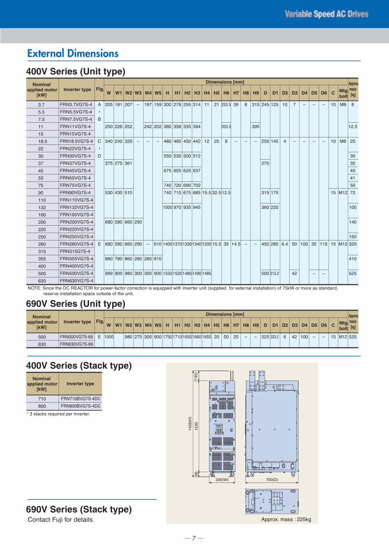
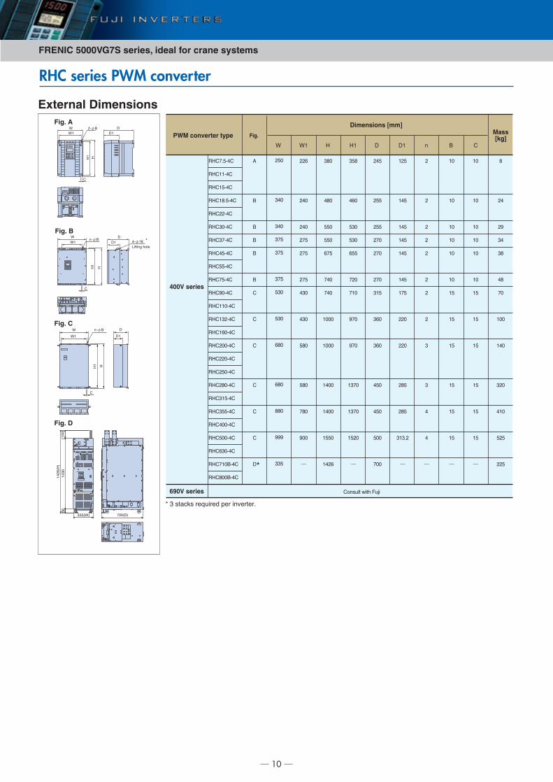
External Dimensions
Fig. C (Internal mounting type)
Fig. A (Internal mounting type) Fig. B (External cooling type)
Fig. D (External cooling type) KEYPAD (Common to all models)
Fig. E (Type common to internal mounting, external cooling, and stand-alone)
A
7
Inverter type
�"# E /��6� 5� �� � &�#"� 4�� :�@��4�6 �� 6����6 ��� �- �F7�::�� @� 5 ��?�� �� 7�� 9-7::���� 4�� �D ����� ��- ���� ���; �4 ��1� �� .��� �- - ������G
��-��?� ��- ���� ��� -:�6� �7 -��� �4 5� 7�� 8
��� �6 )7I� 4�� �� ���-8
400V Series (Unit type)Nominal
applied motor[kW] W1W W2
�8�
�8�
�8�
��
��
��8�
��
�3
��
��
��
��
�3
��3
���
��3
�33
��3
��3
��3
���
���
�33
�33
��3
)���8�+(�/�
)���8�+(�/�
)���8�+(�/�
)����+(�/�
)����+(�/�
)����8�+(�/�
)����+(�/�
)���3+(�/�
)����+(�/�
)����+(�/�
)����+(�/�
)����+(�/�
)���3+(�/�
)����3+(�/�
)�����+(�/�
)����3+(�/�
)���33+(�/�
)����3+(�/�
)����3+(�/�
)����3+(�/�
)�����(�/�
)�����+(�/�
)���33+(�/�
)���33+(�/�
)����3+(�/�
�3�
��3
��3
���
��3
��3
��3
��3
���
&
J
�
J
�
���
���
��3
���
��3
��3
��3
��3
�33
�3�
���
���
���
��3
��3
��3
��3
��3
W3
K
K
��3
��3
��3
�33
W4
���
���
K
K
��3
�33
W5
���
�3�
K
��3
��3
�33
H
�33
��3
��3
��3
���
��3
��3
�333
��33
���3
H1
���
���
��3
��3
���
��3
��3
��3
���3
���3
H2
���
���
��3
�33
���
��3
���
���
���3
���3
H3
���
���
���
���
���
�3�
���
���
���3
���3
H4
��
��
��8�
����
����
H5
��
��
��8�
��8�
H6
���8�
���8�
�
��8�
��
H7
��
K
��8�
H8
�
K
K
H9
���
���
K
K
D
���
���
��3
���
��3
��3
�33
D1
���
���
���
��3
���
���8�
D2
�3
�
�8�
D3
�
K
�3
��
C
�3
�3
��
��
!�
!�
!��
!��
�
��8�
��
�3
��
�3
��
�3
��
�33
��3
��3
��3
��3
���
Dimensions [mm]
D4
K
K
�33
D5
K
K
��
K
D6
K
K
���
K
Fig. Approx. mass [kg]
Mtg. bolt
Inverter type
690V Series (Unit type)Nominal
applied motor[kW] W1W W2
�33
��3
)���33+(�/��
)����3+(�/��
�333 ��3
W3
���
W4
�33
W5
�33
H
���3
H1
���3
H2
���3
H3
���3
H4
����
H5
�3
H6
�3
H7
��
H8
K
H9
K
D
���
D1
���8�
D2
�
D3
��
C
�� !�� ���
Dimensions [mm]
D4
�33
D5
K
D6
K
Fig. Approx. mass [kg]
Mtg. bolt
Inverter type
400V Series (Stack type)
690V Series (Stack type)
Nominal applied motor
[kW]
��3
�33
)����3+(�/���
)���33+(�/���
L � - �61- ��F7���� :�� ��?�� ��8
&::��D8 .�-- E ���1�
�339�;
����9�;
9��3;
���3
��
���9�;
External Dimensions
FRENIC 5000VG7S series, ideal for crane systems
8
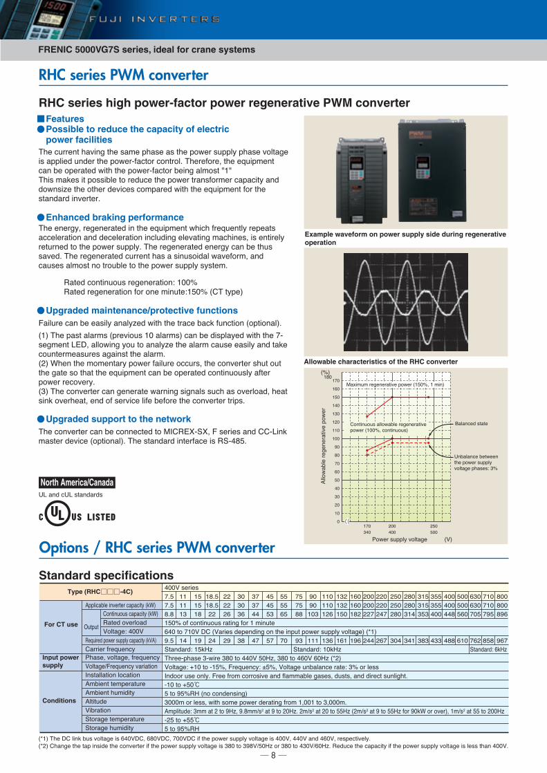
RHC series high power-factor power regenerative PWM converter
Example waveform on power supply side during regenerative operation
Allowable characteristics of the RHC converter
�
��
�
��
��
��
��
�
��
��
���
���
� �
���
���
���
���
�����
��
���
��
���
��
���
!04*� /-''); 60).(7* �9�
�J�
=(:,5-5 �*7*1*�(.,6* '04*� ����J< � 5,1�
�01.,1-0-/ ())04(A)* �*7*1*�(.,6*'04*� ����J< +01.,1-0-/�
�()(1+*3 /.(.*
�1A()(1+* A*.4**1.2* '04*� /-'');60).(7* '2(/*/K �J
Features
#2* *1*�7;< �*7*1*�(.*3 ,1 .2* *8-,'5*1. 42,+2 ��*8-*1.); �*'*(./(++*)*�(.,01 (13 3*+*)*�(.,01 ,1+)-3,17 *)*6(.,17 5(+2,1*/< ,/ *1.,�*);�*.-�1*3 .0 .2* '04*� /-'');� #2* �*7*1*�(.*3 *1*�7; +(1 A* .2-//(6*3� #2* �*7*1*�(.*3 +-��*1. 2(/ ( /,1-/0,3() 4(6*�0�5< (13+(-/*/ ()50/. 10 .�0-A)* .0 .2* '04*� /-''); /;/.*5�
Enhanced braking performance
(,)-�* +(1 A* *(/,); (1();L*3 4,.2 .2* .�(+* A(+@ �-1+.,01 �0'.,01()��
��� #2* '(/. ()(�5/ �'�*6,0-/ �� ()(�5/� +(1 A* 3,/')(;*3 4,.2 .2* �/*75*1. �BF< ())04,17 ;0- .0 (1();L* .2* ()(�5 +(-/* *(/,); (13 .(@*+0-1.*�5*(/-�*/ (7(,1/. .2* ()(�5�� � &2*1 .2* 505*1.(�; '04*� �(,)-�* 0++-�/< .2* +016*�.*� /2-. 0-..2* 7(.* /0 .2(. .2* *8-,'5*1. +(1 A* 0'*�(.*3 +01.,1-0-/); (�.*�'04*� �*+06*�;���� #2* +016*�.*� +(1 7*1*�(.* 4(�1,17 /,71()/ /-+2 (/ 06*�)0(3< 2*(./,1@ 06*�2*(.< *13 0� /*�6,+* ),�* A*�0�* .2* +016*�.*� .�,'/�
Upgraded maintenance/protective functions
#2* +016*�.*� +(1 A* +011*+.*3 .0 =>��BC��C< /*�,*/ (13 ����,1@5(/.*� 3*6,+* �0'.,01()�� #2* /.(13(�3 ,1.*��(+* ,/ �������
Upgraded support to the network
#2* +-��*1. 2(6,17 .2* /(5* '2(/* (/ .2* '04*� /-''); '2(/* 60).(7*,/ (''),*3 -13*� .2* '04*���(+.0� +01.�0)� #2*�*�0�*< .2* *8-,'5*1.+(1 A* 0'*�(.*3 4,.2 .2* '04*���(+.0� A*,17 ()50/. M�M#2,/ 5(@*/ ,. '0//,A)* .0 �*3-+* .2* '04*� .�(1/�0�5*� +('(+,.; (133041/,L* .2* 0.2*� 3*6,+*/ +05'(�*3 4,.2 .2* *8-,'5*1. �0� .2*/.(13(�3 ,16*�.*��
Possible to reduce the capacity of electric power facilities
�(.*3 +01.,1-0-/ �*7*1*�(.,01K ���J�(.*3 �*7*1*�(.,01 �0� 01* 5,1-.*K���J ��# .;'*�
))04(A)*�*7*1*�(.,6*'04*�
North America/Canada�� (13 +�� /.(13(�3/
RHC series PWM converter
Options / RHC series PWM converter
Standard specifications
���� #2* F� ),1@ A-/ 60).(7* ,/ ���9F�< ���9F�< ��9F� ,� .2* '04*� /-''); 60).(7* ,/ ���9< ���9 (13 ���9< �*/'*+.,6*);�
�� � �2(17* .2* .(' ,1/,3* .2* +016*�.*� ,� .2* '04*� /-''); 60).(7* ,/ ��� .0 ���9����L 0� ��� .0 ���9����L� �*3-+* .2* +('(+,.; ,� .2* '04*� /-''); 60).(7* ,/ )*// .2(1 ���9�
H-.'-.
��
��
���
���
��
��
��
��
�
�
��
��
��
��
�
�
��
�
��
��
��
�
��
��
��
�
�
�
��
��
��
��
���
���
���
���
� �
���
��
��
���
���
���
���
��
���
��
��
��
�
�
�
�
��
��
��
���
��
��
���
���
���
���
���
���
���
���
���
���
���
���
���
���
���
���
���
���
���
���
��
�
��
��
��
���
���
���
���
��
��
��
��
��
����
����
�
���9 /*�,*/
���J 0� +01.,1-0-/ �(.,17 �0� � 5,1-.*
��� .0 ��9 F� �9(�,*/ 3*'*13,17 01 .2* ,1'-. '04*� /-''); 60).(7*� ����
�.(13(�3K ��@�L �.(13(�3K ��@�L �.(13(�3K �@�L#2�**�'2(/* ��4,�* ��� .0 ���9 ���L< ��� .0 ���9 ���L �� �
90).(7*K D�� .0 ���J< �*8-*1+;K O�J< 90).(7* -1A()(1+* �(.*K �J 0� )*//
>1300� -/* 01);� �** ��05 +0��0/,6* (13 �)(55(A)* 7(/*/< 3-/./< (13 3,�*+. /-1),72.�
��� .0 D��℃� .0 ��J�� �10 +013*1/,17�
����5 0� )*//< 4,.2 /05* '04*� 3*�(.,17 ��05 �<��� .0 �<���5�
5'),.-3*K �55 (. .0 ��L< ���55�/ (. � .0 ��L� 5�/ (. � .0 ���L � 5�/ (. � .0 ���L �0� ��@& 0� 06*��< �5�/ (. �� .0 ���L
� � .0 D��℃ � .0 ��J��
Type (RHC -4C)
For CT use
''),+(A)* ,16*�.*� +('(+,.; �@&�
!2(/*< 60).(7*< ��*8-*1+;
90).(7*��*8-*1+; 6(�,(.,01
>1/.())(.,01 )0+(.,01
5A,*1. .*5'*�(.-�*
5A,*1. 2-5,3,.;
).,.-3*
9,A�(.,01
�.0�(7* .*5'*�(.-�*
�.0�(7* 2-5,3,.;
�*8-,�*3 '04*� /-''); +('(+,.; �@9 �
�(��,*� ��*8-*1+;
�01.,1-0-/ +('(+,.; �@&�
�(.*3 06*�)0(3
90).(7*K ���9
Input power supply
Conditions
9
RHC series PWM converter
���� �������� ���� ���� �� ��� �� � ���
��
��
��
����
��
�
��
��
�
��
���
��
���
��
�
��
��
���
���
���
���
���
��
���
���
���
��������
��������
��������
����������
��� ���
��������
�������
��������
��������
�������
��������
���������
����� ���
���������
��� �����
��� ����
��� �����
��� �����
���������
���������
���������
���������
���������
���������
����������
�������
�������
���� �
������
�������
������
��������
��������
���� ��
���� ���
��������
��������
��������
��������
��������
�������
��������
�
�
�
�
�
�
�
�
�
�
�
�
�
�
�
�
�
������ ����
������� ����
���� �� �����
������� �����
������� �� ��
������� �����
������� �����
�������
��� ��
��� ���
�������
�������
�������
�������
�������
������
�������
�
�
�
�
�
�
�
�
�
�
�
�
�
�
�
�
�
�������
�������
���� �
������
�������
������
��������
��������
���� ��
���� ���
��������
��������
��������
��������
��������
�������
��������
�
�
�
�
�
�
�
�
�
�
�
�
�
�
�
�
�
������
������
��� �
�����
������
�����
�������
�������
��� ��
��� ���
�������
�������
�������
�������
�������
������
�������
�
�
�
�
�
�
�
�
�
�
�
�
�
��
��
��
��
�����
������
������
�����
����
���� �
�����
�����
�����
����
�����
������
�����
�����
�����
�
�
�
�
�
�
�
�
�
�
�
�
�
�
�
�����
����
�����
�
�
�
������
������
������
�����
������
�
�
�
�
�
����������
����������
���������
�����������
�����������
����� �����
�����������
��!�����
��!�����
�"������
�!������#
�! �����
��� ���
#$��� ���%
���������
��& ���
���������
����� � �
������� ��
������� ��
� '(�())*) +,�+-,./�
�
�
�
�
�
Equipment List
400Vseries
690Vseries
Voltage Applicablemotor
PWMconverter
Boosting reactor Filter reactor Filter capacitor Filter resistor Charging resistor Fuse Charging circui contactor Power supplycontactor
Filter circuitcontactor
� '(�())*) +,�+-,./�
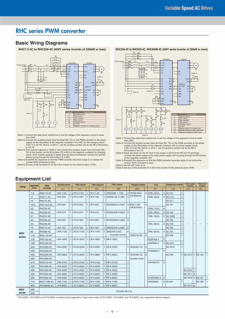
Basic Wring Diagrams
��0.* �� �011*+. .2* /.*'�3041 .�(1/�0�5*� .0 /*. .2* 60).(7* 0� .2* /*8-*1+* +,�+-,. .0 )04*�.2(1 �9�
��0.* � �011*+. .2* (-:,),(�; '04*� ,1'-. .*�5,1() ���< #�� 01 .2* !&= +016*�.*� .0 .2* '04*�/-''); 6,( .2* ��+01.(+. 0� .2* 5(71*.,+ +01.(+.0� �� 0� =�� �0� .2* +2(�7,17 +,�+-,.�>� .2* � ,/ �����< �����< 0� �����< -/* .2* (-:,),(�; +01.(+. -1,. (/ .2* =�?/ ��+01.(+.0� .2* ��
��0.* �� >� .2* ,16*�.*� +('(+,.; ,/ ��@& 0� )*// +011*+. .2* (-:,),(�; '04*� ,1'-. .*�5,1()/ ���<#�� 0� .2* ,16*�.*� 6,( .2* ��+01.(+. �� 0� =�� 0� .2* 5(71*.,+ +01.(+.0� �0� +2(�7,17+,�+-,.� >� .2* ,16*�.*� +('(+,.; ,/ 2,72*� .2(1 .2* (A06*�5*1.,01*3< +011*+. .2* ,16*�.*�4,.20-. 70,17 .2�0-72 .2* ��+01.(+. �� 0� =���
��0.* �� B/.(A),/2 .2* /*8-*1+* /0 .2(. .2* !&= +016*�.*� A*+05*/ �*(3; .0 �-1 A*�0�* .2*,16*�.*� ��� +055(13 ,/ ,1'-.�
��0.* �� �*. (1; 0� .2* .*�5,1()/ C� .0 C� 0� .2* ,16*�.*� �0� .2* *:.*�1() ()(�5 �#����
=� �� ��
��
���� !�D�
� ��
���# ��E�
!�D�
��E�
�
#
��
��
#�
��
#�
�
��
���
��#
�=
�
9
&
&F
�=
��
�
��
G�
G��
���
���
�
��
*
+
3
�
��
#�
C�(#��)
�=
��
���
���
��0.* ��
�016*�.*� >16*�.*�
��0.* ��
��0.* ��
��0.* ��
3C
�
>=
�
(
A���
���=�
*
�
(A
�
=� ��� C �
*
�
� 0� =�
��
��+
F*6,+* �(5*�;5A0)
��
��
��
��
��
�
�� ��
����
� ��
���#
�
#
��
��
#�
��
#�
�
��
���
��#
�=
�
9
&
&F
�=
��
�
��
���
���
�
��
G�
G��
7
*
�
2
��
#�
C�(#��)
�=
��
���
���
��0.* ��
��0.* ��
��0.* ��
��0.* ��
��0.* ��
��0.* �
����
�
>=
(
A
�������FG �FG
(A
� #
�FG � �
�
�
�
�
�
���
2
7
��
��
� #
�FG
�
� C
� #
+3
� C
�#H!
� C
�
�
��
�
�
+
3
*
��0.* �� �011*+. .2* /.*'�3041 .�(1/�0�5*� .0 /*. .2* 60).(7* 0� .2* /*8-*1+* +,�+-,. .0 )04*�.2(1 �9�
��0.* � �011*+. .2* (-:,),(�; '04*� ,1'-. .*�5,1() ���< #�� 01 .2* !&= +016*�.*� .0 .2* '04*�/-''); 6,( .2* ��+01.(+. 0� .2* 5(71*.,+ +01.(+.0� �� � �0� '04*� /-''); +,�+-,.�>� .2* � ,/ �����< �����< 0� �����< -/* .2* (-:,),(�; +01.(+. -1,. (/ .2* =�?/��+01.(+. 0� .2* ��
��0.* �� �,1+* .2* '04*� �0� .2* � �(1/ ,1 .2* ,16*.*� ,/ �*3 ��05 .2* �� (13 #� .*�5,1()/<+011*+. .2* '04*� /-''); .0 .2* 5(,1 '04*� /-''); 4,.20-. 70,17 .2�0-72 .2* ��+01.(+.0� .2* 5(71*.,+ +01.(+.0� �� ��
��0.* �� B/.(A),/2 .2* /*8-*1+* /0 .2(. .2* !&= +016*�.*� A*+05*/ �*(3; .0 �-1 A*�0�* .2*,16*�.*� ��� +055(13 ,/ ,1'-.�
��0.* �� �*. .2* � # .,5*� (. �/���0.* �� �*. (1; 0� .2* .*�5,1()/ C� .0 C� 0� .2* ,16*�.*� �0� .2* *:.*�1() ()(�5 �#����
�016*�.*� >16*�.*�
�;5A0) F*6,+* �(5*
��
��
��
��
��
�
�
�
RHC7.5-4C to RHC220-4C (400V series inverter of 220kW or less) RHC250-4C to RHC630-4C, RHC800B-4C (400V series inverter of 250kW or more)
�00/.,17 �*(+.0�
,).*� �*(+.0�
,).*� +('(+,.0�
,).*� �*/,/.0�
�2(�7,17 �*/,/.0�
� �-/*
=(71*.,+ +01.(+.0� �0� +2(�7,17 +,�+-,.
!04*� /-'');
�*(3;.0�-1
�*(3;.0�-1
!04*� /-'');
�00/.,17 �*(+.0�
,).*� �*(+.0�
,).*� +('(+,.0�
,).*� �*/,/.0�
�2(�7,17 �*/,/.0�
� �-/*
=(71*.,+ +01.(+.0� �0� +2(�7,17 +,�+-,.
=(71*.,+ +01.(+.0� �0� '04*� /-''); +,�+-,.
=(71*.,+ +01.(+.0� �0� �,).*� +,�+-,.
� �������< ������� (13 ������� +01/,/./ 0� .40 +('(+,.0�/� �'01 *(+2 0�3*� 0� �������< ������� (13 �������< .40 +('(+,.0�/ 4,)) A* /2,''*3�
�01/-). 4,.2 -I,
FRENIC 5000VG7S series, ideal for crane systems
10
RHC series PWM converter
External DimensionsFig. A
'
'� �
�
&�
&
��φ
Fig. B'
'�
&�
&
�
�
��φ��φ���$0"$�� ����
Fig. C
Fig. D
'
�'�
&� &
�
��φ
PWM converter type' '� & &� � � �
�&�������
�&������
�&������
�&��������
�&������
�&������
�&������
�&������
�&������
�&������
�&������
�&�������
�&�������
�&������
�&�������
�&�������
�&�������
�&�������
�&�������
�&�������
�&�������
�&�������
�&������
�&�������
�&�������
�
�
�
�
�
�
�
6
���
���
���
���
���
���
���
���
��
��
���
���
���
��
���
���
���
���
���
���
���
���
���
���
���
―
���
���
���
���
��
���
���
����
����
����
����
����
���
���
��
���
���
��
���
���
���
���
����
����
����
―
���
���
���
���
���
���
���
��
��
���
���
���
���
���
���
���
���
���
���
���
���
���
���
���
�����
―
�
�
�
�
�
�
�
�
�
�
�
�
―
��
��
��
��
��
��
��
��
��
��
��
��
―
��
��
��
��
��
��
��
��
��
��
��
��
―
�
��
��
��
��
��
��
���
���
���
���
���
���
400V series
690V series
Fig.
Dimensions [mm]Mass[kg]
���7 8
���7&8
7���8
����
���7'8
6 � 2"%-92 !�:.$!�4 5�! $�;�!"�!�
���2.�" 3$"� �./$
11
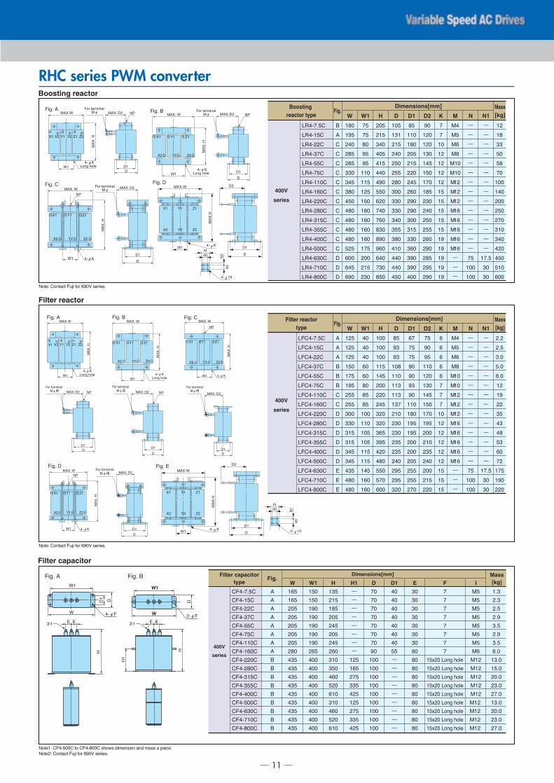
RHC series PWM converterBoosting reactor
Filter reactor
Filter capacitor
400V
series
400V
series
400V
series
Boosting reactor type
Dimensions[mm]
���
���
���
���
���
���
���
���
���
���
���
���
���
���
��
��
��
�
�
�
�
�
�
�
�
�
�
�
�
�
W
��
��
��
��
��
���
���
���
���
��
��
��
��
���
���
���
���
W1
���
���
���
���
���
���
���
���
��
���
��
���
���
��
��
���
���
H
���
���
���
���
���
���
���
���
���
���
���
���
���
���
���
���
���
D
��
���
���
���
���
���
���
��
���
���
���
���
���
��
���
���
���
D1
��
���
���
���
���
���
���
���
���
���
���
���
��
���
���
���
���
D2
�
�
��
��
��
��
��
��
��
��
��
��
��
��
��
��
��
K
ー
ー
ー
ー
ー
ー
ー
ー
ー
ー
ー
ー
ー
ー
����
��
��
ー
ー
ー
ー
ー
ー
ー
ー
ー
ー
ー
ー
ー
ー
��
���
���
��
��
�
��
���
���
���
���
���
��
��
��
��
��
ー
ー
ー
��
��
��
��
��
��
���
���
���
���
���
���
���
���
���
���
��
N1NM
Mass[kg]
Fig.
��������
�������
�������
�������
�������
�������
��������
�������
��������
��������
��������
��������
��������
��������
�������
��������
��������
Filter capacitortype
Dimensions[mm]
���
���
���
���
���
���
���
��
����
����
����
����
����
����
����
����
����
Mass[kg]
��
��
���
���
���
���
���
���
���
���
���
���
���
���
���
���
���
�
�
�
�
�
�
�
�
W
���
���
���
���
���
���
���
��
���
���
���
���
���
���
���
���
���
W1
���
���
���
���
���
���
���
��
���
���
��
���
��
���
��
���
��
H
ー
ー
ー
ー
ー
ー
ー
ー
���
��
���
���
���
���
���
���
���
H1
��
��
��
��
��
��
��
��
���
���
���
���
���
���
���
���
���
D
��
��
��
��
��
��
��
��
ー
ー
ー
ー
ー
ー
ー
ー
ー
D1
��
��
��
��
��
��
��
��
��
��
��
��
��
��
��
��
��
E
�
�
�
�
�
�
�
�
����� ���� ����
����� ���� ����
����� ���� ����
����� ���� ����
����� ���� ����
����� ���� ����
����� ���� ����
����� ���� ����
����� ���� ����
F
��
��
��
��
��
��
��
�
���
���
���
���
���
���
���
���
���
IFig.
��������
�������
�������
�������
�������
�������
��������
�������
��������
��������
��������
��������
��������
��������
�������
��������
��������
Filter reactortype
Dimensions[mm]
���
���
���
���
���
���
���
���
���
���
���
���
���
���
���
���
���
�
�
�
�
�
�
�
�
W
��
��
��
�
�
��
��
��
���
���
���
���
���
���
���
��
��
W1
���
���
���
���
���
���
���
���
���
���
��
���
���
���
���
���
��
H
��
��
��
���
���
���
���
���
���
���
���
���
���
���
���
���
���
D
�
��
��
��
��
��
��
���
���
���
���
���
���
���
���
���
���
D1
��
��
��
���
���
���
���
���
���
���
���
���
���
���
���
���
���
D2
�
�
�
��
��
��
��
��
��
��
��
��
K
��
��
�
��
���
���
���
���
���
��
��
��
��
��
ー
ー
ー
���
���
���
���
���
��
��
��
��
��
��
��
�
��
���
���
���
M
ー
ー
ー
ー
ー
ー
ー
ー
ー
ー
ー
ー
ー
ー
��
���
���
N
ー
ー
ー
ー
ー
ー
ー
ー
ー
ー
ー
ー
ー
ー
����
��
��
N1
Mass[kg]
Fig.
���������
��������
��������
��������
��������
��������
���������
��������
���������
���������
���������
���������
���������
���������
��������
���������
���������
�������� � �
��! "�!#$�%��φ
�
����&
'�
�� �� (� (� )� )�
'
��φ*���� ����
�$�� ����� �
��! "�!#$�%��φ
(� )���
(� )���
���� '
����&
'�
�
�
��φ*���� ����
�$��
���� ���! "�!#$�%��φ
�
����'
����&
�� (� )�
�� (� )�
'�
�
�$�� �
��φ*
'�
'
�
��φ�
� �
&
��+
�$�� �
W1
W
��φ�
'�
'
� �
&
3-I
&�
�$��
�� �� (� (� )� )�
����'�$�� �
����&
'�
��φ*���� ����
���� � �
��! "�!#$�%��φ用
�
(� )���
(� )���
'�
��φ*���� ����
���� '�$��
����&
���� �
��! "�!#$�%��φ用
�
�
�� (� )�
�� (� )�
����'
�
�$�� �
����&
'� ��φ*
���� �
��! "�!#$�%��φ用
�
�$��
�� (� )�
�� (� )�
����'
�
����&
'� ��φ*
���� ���! "�!#$�%��φ用
�
��"�, ���"%-" �./$ 0�! ��1 2�!$�2�
��"�, ���"%-" �./$ 0�! ��1 2�!$�2�
��"��, �������� "� �������� 2��32 4$#��2$�� %�4 #%22 % 5$�-��
��"��, ���"%-" �./$ 0�! ��1 2�!$�2�
'�
����'
)�(���
)�(���
����&
��φ*
��φ��
�
��
��
� �
�$��
'�
����'
)�(���
)�(���
����&
��φ* ��φ��
�
��
��
�
�
�$�� �
��
��
FRENIC 5000VG7S series, ideal for crane systems
12
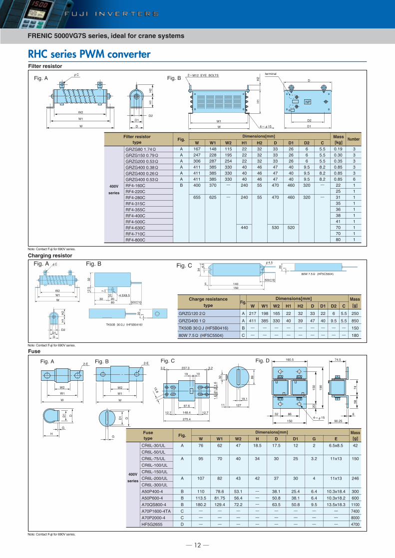
RHC series PWM converter
Fuse
Filter resistor
Charging resistor
���� � φ�
�
�
�
��
�
�
�
���� �
��±�
��
��
��
�
φ��
��� �� ٠��� � ���
����� �
�
�����
�� ���
��
�
��±�
�� �� ��� ��� �����
�
���� � ���� �
�
�
�
��
��
�
�
�
�
�
��
�
��
400V
series
Filter resistortype
Dimensions[mm]
���
����
���
���
���
���
�
�
��
��
�
��
��
��
Mass[kg]
�
�
�
�
�
�
Number
��
��
���
�
�
�
���
�
�
�
�
�
�
�
�
W��
�
��
��
��
��
���
�
W1
�
�
���
���
���
ー
ー
W2
��
��
��
��
��
���
H1�
�
�
��
��
��
H2��
��
��
��
��
��
���
���
��
D�
�
�
��
��
��
���
���
�
D1�
�
�
��
��
��
��
��
D2 �
�
�
��
��
��
ー
ー
CFig.
�� ��� ����� � � ������ ��� �� ��� ���� ������ ���� ����� ���� �� ��������
������
�������
����� �
����� �
��������
���� ���
��������
�������
��������
Charge resistancetype
Dimensions[mm]
�
�
ー
ー
�
�
�
�
W
��
��
ー
ー
W1
�
���
ー
ー
W2
��
ー
ー
H1
�
��
ー
ー
H2
��
��
ー
ー
D
�
��
ー
ー
D2
��
ー
ー
D1
�
�
ー
ー
�
� �
�
��
C
Mass[g]
Fig.
�� �� Ω
�� ���� Ω
�� �� ��� ��� �����
��� �� ٠��� � ���
Fusetype
Dimensions[mm]
Mass[g]
��
�
��
�
��
���
ー
ー
ー
�
�
�
�
�
�
�
�
�
W
�
��
�
����
���
���
ー
ー
ー
W1
��
��
��
��
���
��
ー
ー
ー
W2
��
��
�
ー
ー
ー
ー
ー
ー
H
��
��
��
���
���
���
ー
ー
ー
D
��
��
���
���
ー
ー
ー
D1
��
�
���
���
��
ー
ー
ー
G
�� !��
!�
!�
���!���
���!��
�� !���
ー
ー
ー
�
�
��
���
���
��
����
����
����
EFig.
���"���#$"
���"� �#$"
���"�� #$"
���"���#$"
���"� �#$"
���"���#$"
���"����#$"
� �%�����
� �%�����
���&'�����
���%�������
���%�����
�� ��
400V
series
���� �
��
�
��
�
� �(
�� ���� ��
�� ������
� ��
����
��
��
��
��
���� �φ�
�
�
�
�
�
�
�
�
���� �
)%
�
�
�
�
� �-φ
�
�
-* �+� �,"�'-./0�123
)4-.5 �41-26- �78� 94/ ���: ;./�.;�
)4-.5 �41-26- �78� 94/ ���: ;./�.;�
)4-.5 �41-26- �78� 94/ ���: ;./�.;�
��� ���
���
�
�
���
�
�
��
��
�
��×φ
���� �
13
Braking resistor
Braking unit
Powerregenerative PWM converter, RHC series
Dedicated filterfor the RHC series
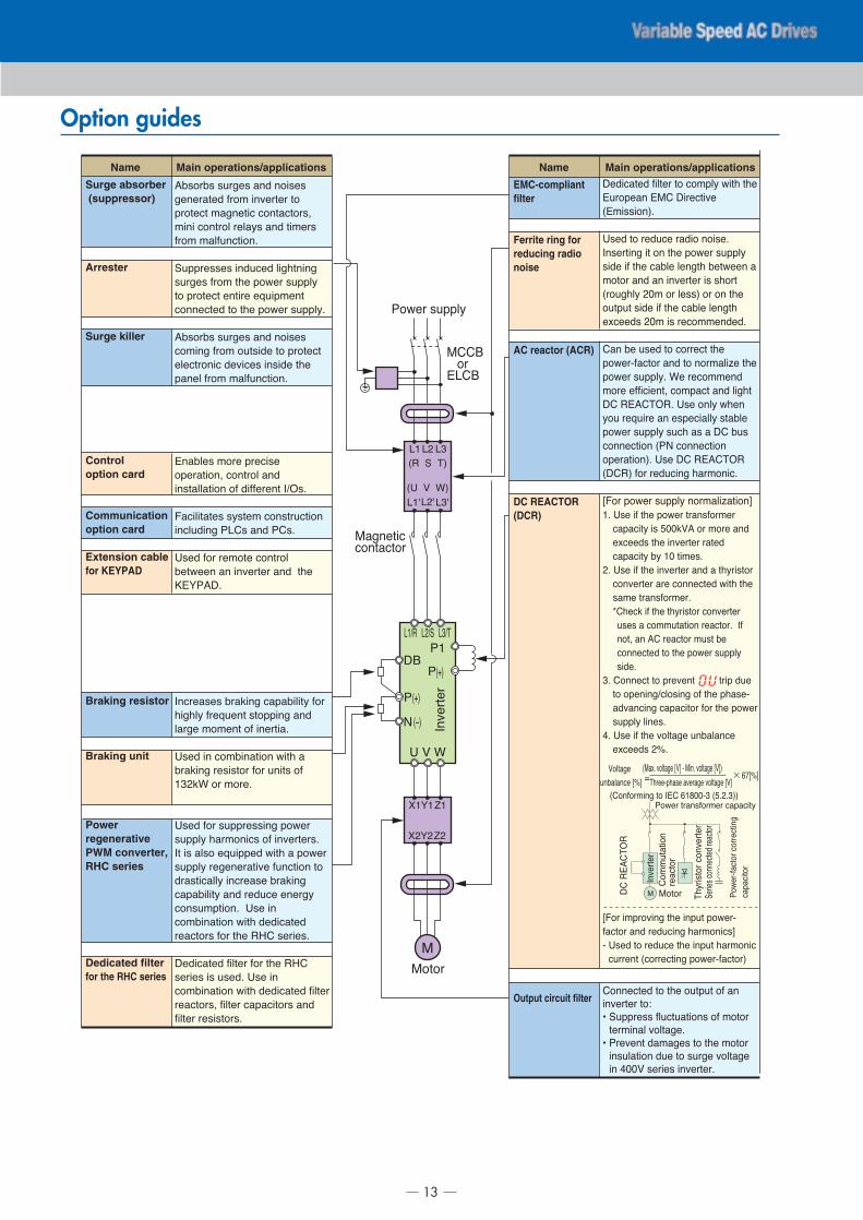
Option guides
Surge absorber (suppressor)
Arrester
Surge killer
Control option card
Communication option card
Extension cablefor KEYPAD
�<;4/<; ;7/�.; 21= 14�;.;
�.1./2-.= 9/40 �1>./-./ -4
?/4-.6- 02�1.-�6 641-26-4/;@
0�1� 641-/43 /.32A; 21= -�0./;
9/40 0239716-�41�
'7??/.;;.; �1=76.= 3��B-1�1�
;7/�.; 9/40 -B. ?4C./ ;7??3A
-4 ?/4-.6- .1-�/. .D7�?0.1-
6411.6-.= -4 -B. ?4C./ ;7??3A�
�<;4/<; ;7/�.; 21= 14�;.;
640�1� 9/40 47-;�=. -4 ?/4-.6-
.3.6-/41�6 =.>�6.; �1;�=. -B.
?21.3 9/40 0239716-�41�
�12<3.; 04/. ?/.6�;.
4?./2-�41@ 641-/43 21=
�1;-2332-�41 49 =�99./.1- E#,;�
�26�3�-2-.; ;A;-.0 641;-/76-�41
�1637=�1� %"�; 21= %�;�
$;.= 94/ /.04-. 641-/43
<.-C..1 21 �1>./-./ 21= -B.
��+%���
E16/.2;.; </2F�1� 62?2<�3�-A 94/
B��B3A 9/.D7.1- ;-4??�1� 21=
32/�. 040.1- 49 �1./-�2�
$;.= �1 640<�12-�41 C�-B 2
</2F�1� /.;�;-4/ 94/ 71�-; 49
�F� 4/ 04/.�
$;.= 94/ ;7??/.;;�1� ?4C./
;7??3A B2/041�6; 49 �1>./-./;�
E- �; 23;4 .D7�??.= C�-B 2 ?4C./
;7??3A /.�.1./2-�>. 9716-�41 -4
=/2;-�6233A �16/.2;. </2F�1�
62?2<�3�-A 21= /.=76. .1./�A
641;70?-�41� $;. �1
640<�12-�41 C�-B =.=�62-.=
/.26-4/; 94/ -B. ��� ;./�.;�
�.=�62-.= 9�3-./ 94/ -B. ���
;./�.; �; 7;.=� $;. �1
640<�12-�41 C�-B =.=�62-.= 9�3-./
/.26-4/;@ 9�3-./ 62?26�-4/; 21=
9�3-./ /.;�;-4/;�
EMC-compliant filter
Ferrite ring for reducing radio noise
AC reactor (ACR)
DC REACTOR (DCR)
Output circuit filter
�.=�62-.= 9�3-./ -4 640?3A C�-B -B.
�7/4?.21 �*� ��/.6-�>.
��0�;;�41��
$;.= -4 /.=76. /2=�4 14�;.�
E1;./-�1� �- 41 -B. ?4C./ ;7??3A
;�=. �9 -B. 62<3. 3.1�-B <.-C..1 2
04-4/ 21= 21 �1>./-./ �; ;B4/-
�/47�B3A �0 4/ 3.;;� 4/ 41 -B.
47-?7- ;�=. �9 -B. 62<3. 3.1�-B
.!6..=; �0 �; /.6400.1=.=�
�21 <. 7;.= -4 64//.6- -B.
?4C./�926-4/ 21= -4 14/023�G. -B.
?4C./ ;7??3A� �. /.6400.1=
04/. .99�6�.1-@ 640?26- 21= 3��B-
�� �����,�� $;. 413A CB.1
A47 /.D7�/. 21 .;?.6�233A ;-2<3.
?4C./ ;7??3A ;76B 2; 2 �� <7;
6411.6-�41 �%) 6411.6-�41
4?./2-�41�� $;. �� �����,�
����� 94/ /.=76�1� B2/041�6�
H�4/ ?4C./ ;7??3A 14/023�G2-�41I
� $;. �9 -B. ?4C./ -/21;94/0./
62?26�-A �; ��F:� 4/ 04/. 21=
.!6..=; -B. �1>./-./ /2-.=
62?26�-A <A � -�0.;�
� $;. �9 -B. �1>./-./ 21= 2 -BA/�;-4/
641>./-./ 2/. 6411.6-.= C�-B -B.
;20. -/21;94/0./�
J�B.6F �9 -B. -BA/�;-4/ 641>./-./
7;.; 2 64007-2-�41 /.26-4/� E9
14-@ 21 �� /.26-4/ 07;- <.
6411.6-.= -4 -B. ?4C./ ;7??3A
;�=.�
�� �411.6- -4 ?/.>.1- -/�? =7.
-4 4?.1�1�#634;�1� 49 -B. ?B2;.�
2=>216�1� 62?26�-4/ 94/ -B. ?4C./
;7??3A 3�1.;�
�� $;. �9 -B. >43-2�. 71<23216.
.!6..=; K�
H�4/ �0?/4>�1� -B. �1?7- ?4C./�
926-4/ 21= /.=76�1� B2/041�6;I
� $;.= -4 /.=76. -B. �1?7- B2/041�6
67//.1- �64//.6-�1� ?4C./�926-4/�
�411.6-.= -4 -B. 47-?7- 49 21
�1>./-./ -45
L '7??/.;; 9376-72-�41; 49 04-4/
-./0�123 >43-2�.�
L %/.>.1- =202�.; -4 -B. 04-4/
�1;732-�41 =7. -4 ;7/�. >43-2�.
�1 ���: ;./�.; �1>./-./�
Main operations/applicationsName Main operations/applicationsName
�*2!� >43-2�. H:I � *�1� >43-2�. H:I�:43-2�.
71<23216. HKI M�B/..�?B2;. 2>./2�. >43-2�. H:I× ��HKI
��4194/0�1� -4 E�� ������ � �����
*4-4/*
%4C./ -/21;94/0./ 62?26�-A
E1>./-./
�������,�
�4007-2-�41
/.26-4/
%4C./�926-4/64//.6-�1�
62?26�-4/
'./�.;6411.6-.=/.26-4/
�BA/�;-4/641>./-./
*4-4/
*
%4C./ ;7??3A
"#'"#�
""
�� ' ��
"�
"N
�$ : ��
"N"�N
�+
�+
"�#�
$ : �
%
%�O���
%�O�
)�P�
*���4/
�"��
E1>./-./
*2�1.-�6641-26-4/
FRENIC 5000VG7S series, ideal for crane systems
14
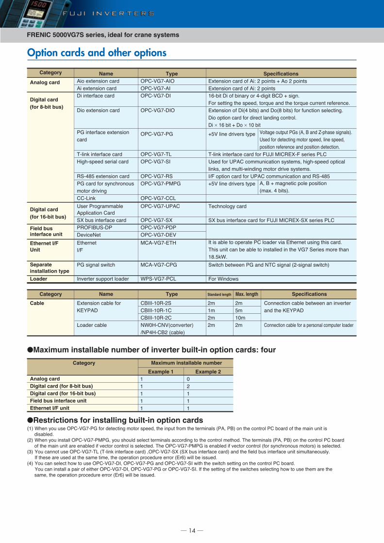
Option cards and other options
Category
Analog card
Digital card (for 8-bit bus)
Digital card (for 16-bit bus)
Field bus interface unit
Ethernet I/FUnit
Separate installation type
Loader
Name��� �������� ��
�� �������� ��
�� �������� ��
��� �������� ��
�� �������� ��������
��
������ �������� ��
�������� ����� ��
������ �������� ��
�� �� ��� �������
!���� ��"���
##�$���
%�� ������!!�&��
���������� #��
�' & �������� ��
��()*+%����
��"��,��
-�������
*.)
�� ����� /���
*�"����� ����� ��� ��
Type(�#�0�1��*(
(�#�0�1��*
(�#�0�1��*
(�#�0�1��*(
(�#�0�1���
(�#�0�1��$
(�#�0�1��*
(�#�0�1���
(�#�0�1��2��
(�#�0�1�##$
(�#�0�1�%��#
(�#�0�1��'
(�#�0�1����
(�#�0�1��-0
2#��0�1�-��
2#��0�1�#��
3���0�1��#$
Specifications-������� �� �� ��4 5 ����� 6 �� 5 �����
-������� �� �� ��4 5 �����
78�&�� �� �� &����� �� �� ���� +#� 6 ���9
)�� ������ ��� ��� : ���; � �� ��� ���; � ����� ��������9
-������� �� ��<� &��= �� ��<� &��= ��� � ����� �������9
��� ������ �� ��� ���� ��� ��� ������9
�� × 78 &�� 6 �� × 7> &��
6�0 ���� ��"�� ����
������ �������� �� ��� )%?* 2*#�-'�) ���� �$#
%� ��� %��# �!! ������� ���!: �������� ������
����: �� ! ����/�� ��� !���� ��"� ���!9
*.) ������ �� ��� %��# �!! ������� �� ������
6�0 ���� ��"�� ����
��������� ��
�' & �������� �� ��� )%?* 2*#�-'��' ���� �$#
*� � �&�� �� ������� �# ��� �� "�� -������� ��� ��� �� 9
��� ��� �� &� �&�� �� ������� �� ��� 0�1 ����� !��� ����
7�9��39
�/��� &��/��� �� �� ,�# ����� <5������ /���=
)�� 3�� �/
Category
Cable
Name
-������� �&�� ���
@-A���
$�� �� �&��
Type
#+***�7>��5�
#+***�7>��7#
#+***�7>��5#
,3>��#,0(converter) .,����#+5 (cable)
Standard length
5!
7!
5!
5!
Max. length
5!
�!
7>!
5!
Specifications
#�������� �&�� &��/��� �� ��"�����
�� ��� @-A���
#�������� �&�� ��� � ������� �!� ��� ��� ��
Category
Analog cardDigital card (for 8-bit bus)Digital card (for 16-bit bus)Field bus interface unitEthernet I/F unit
Example 17
7
7
7
7
Example 2>
5
7
7
7
Maximum installable number
0������ � �� � �� <�: + �� B����� �����=9
%� ��� ������� !���� ��� : ���� ��� :
������� �������� �� ������� �������9
�: + 6 !������ ���� �������
<!��9 � &��=9
●Restrictions for installing built-in option cards<7= 3��� �� � (�#�0�1��� ��� ������� !���� ��� : ��� ��� � ���! ��� ���!���� <��: �+= �� ��� ������ �# &��� �� ��� !��� ��� �
��&�� 9
<5= 3��� �� ������ (�#�0�1��2��: �� �� � ���� ���!���� ��� ��� �� ��� ������ !���� 9 ��� ���!���� <��: �+= �� ��� ������ �# &���
�� ��� !��� ��� ��� ���&�� �� "���� ������ � ����� 9 ��� (�#�0�1��2�� � ���&�� �� "���� ������ <��� ������� !����= � ����� 9
<D= A� ����� � (�#�0�1��$ <������ �������� �� = :(�#�0�1��' <�' & �������� �� = �� ��� ���� & �������� ��� �! ������ ��9
*� ���� ��� � �� ��� �!� ��!�: ��� ��������� ���� �� ����� <-�8= /��� &� � � 9
<�= A� �� ���� ��/ �� � (�#�0�1��*: (�#�0�1��� �� (�#�0�1��* /��� ��� /��� ������ �� ��� ������ �# &��� 9
A� �� ������ � ���� �� ������ (�#�0�1��*: (�#�0�1��� �� (�#�0�1��*9 *� ��� ������ �� ��� /���� ������� ��/ �� � ���! ��� ���
�!�: ��� ��������� ���� �� ����� <-�8= /��� &� � � 9
●Maximum installable number of inverter built-in option cards: four
15
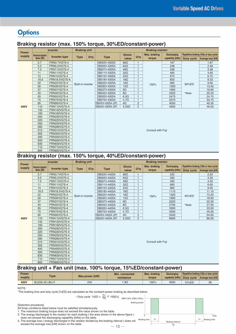
Options
+ ������ ��"�����
#�� �� /��� ) E�
400V
)�,D910�1���
)�,�9�0�1���
)�,19�0�1���
)�,770�1���
)�,7�0�1���
)�,7�9�0�1���
)�,550�1���
)�,D>0�1���
)�,D10�1���
)�,��0�1���
)�,��0�1���
)�,1�0�1���
)�,F>0�1���
)�,77>0�1���
)�,7D50�1���
)�,78>0�1���
)�,5>>0�1���
)�,55>0�1���
)�,5�>0�1���
)�,5�>0�1���
)�,D7�0�1���
)�,D��0�1���
)�,�>>0�1���
)�,�>>0�1���
)�,8D>0�1���
)�,17>0�1���
)�,�>>0�1���
�+>>D0��D>��
�+>>�0��D>��
�+>>10��D>��
�+>770��D>��
�+>7�0��D>��
�+>7�0��D>��
�+>550��D>��
�+>D>0��D>��
�+>D10��D>��
�+>��0��D>��
�+>��0��D>��
�+>1�0��D>��
�+>��0��D>�� <5�=
�+>��0��D>�� <5�=
D91
�9�
19�
77
7�
7�9�
55
D>
D1
��
��
1�
F>
77>
7D5
78>
5>>
55>
5�>
5�>
D7�
D��
�>>
�>>
8D>
17>
�>>
F8G
8�G
��G
D5G
5�G
7�G
78G
75G
FG
�G
89�G
�91G
�G
D95�G
7H
7H
7H
7H
7H
7H
7H
7H
7H
7H
7H
7H
5
5
7�>I
781
5��
DD�
�F�
81�
�DD
FF>
7D�>
788�
5>5�
5�1�
DD1�
�>�>
�F�>
D>I-�J
J
K,���
7981
59��
D9D�
�9F�
891�
�9DD
F9F>
7D9�>
7898�
5>95�
5�91�
DD91�
�>9�>
�F9�>
,(�-4
K��� &������ ��!� �� �� ��� LI-�M ��� �� ���� � ��� ���������/�� &������ � ���&� &���/9
L�������� ���� ��M��� ����� �� ����� ���� &���/ ! � &� ������ �! ������ ��979 ��� !���! ! &������ ���; � �� ��� ���� ��� "�� � ��/� �� ��� ��&��959 ��� ������ ������ �� ��� ������ ��� ��� &������ < ��� ���� ��/� �� ��� �&�"� ��� �� =
�� ��� ���� ��� �������� ���&����� L�3M �� ��� ��&��9D9 ��� �"����� �� < ������ ������ �� ��� ������ �"� � &� ��� &������ �����"�� = �� ���
���� ��� �"����� �� L�3M ��/� �� ��� ��&��9
N � �� ��� I-� O × 7>>LIM�7�>
> ��!�
�+�47�>I <�+%47>>I=
+������ �����"��
�>
+������ ��!� +������ ��!��7 �7
+������ ��/��
Power supply Nominal Applied
Motor [kW] TypeOhmic value Average loss [kW]Duty cycle
Repetitive braking (100s or less cycle)Discharging capability [kWs]
Max. braking torqueInverter type
Inverter Braking unit Braking resistor
Type Q'ty Q'ty
Braking resistor (max. 150% torque, 30%ED/constant-power)
Nominal Applied Motor [kW] Inverter type
Inverter
+ ������ ��"�����
#�� �� /��� ) E�
400V
)�,D910�1���
)�,�9�0�1���
)�,19�0�1���
)�,770�1���
)�,7�0�1���
)�,7�9�0�1���
)�,550�1���
)�,D>0�1���
)�,D10�1���
)�,��0�1���
)�,��0�1���
)�,1�0�1���
)�,F>0�1���
)�,77>0�1���
)�,7D50�1���
)�,78>0�1���
)�,5>>0�1���
)�,55>0�1���
)�,5�>0�1���
)�,5�>0�1���
)�,D7�0�1���
)�,D��0�1���
)�,�>>0�1���
)�,�>>0�1���
)�,8D>0�1���
)�,17>0�1���
)�,�>>0�1���
�+>>D0���>��
�+>>�0���>��
�+>>10���>��
�+>770���>��
�+>7�0���>��
�+>7�0���>��
�+>550���>��
�+>D>0���>��
�+>D10���>��
�+>��0���>��
�+>��0���>��
�+>1�0���>��
�+>��0���>�� <5�=
�+>��0���>�� <5�=
D91
�9�
19�
77
7�
7�9�
55
D>
D1
��
��
1�
F>
77>
7D5
78>
5>>
55>
5�>
5�>
D7�
D��
�>>
�>>
8D>
17>
�>>
F8G
8�G
��G
D5G
5�G
7�G
78G
75G
FG
�G
89�G
�91G
�G
D95�G
7H
7H
7H
7H
7H
7H
7H
7H
7H
7H
7H
7H
5
5
7�>I
555
DD>
��>
88>
F>>
777>
7D5>
7�>>
555>
51>>
DD>>
��>>
��>>
88>>
�>I-�J
J
K,���
5955
D9D>
�9�>
898>
F9>>
7797>
7D95>
7�9>>
5595>
519>>
DD9>>
��9>>
��9>>
889>>
Power supply Type
Ohmic value Average loss [kW]Duty cycle
Repetitive braking (100s or less cycle)Discharging capability [kWs]
Max. braking torque
Braking unit Braking resistor
Type Q'ty Q'ty
Braking resistor (max. 150% torque, 40%ED/constant-power)
Type
400V +%55>��#6+%�) 79FG 7>>I5�> D8>> 7�I-� D8
Power supply
Min. connectedresistance Average loss [kW]Duty cycle
Repetitive braking (100s or less cycle)Discharging capability [kWs]
Max. braking torqueMax.power [kW]
Braking unit + Fan unit (max. 100% torque, 15%ED/constant-power)
FRENIC 5000VG7S series, ideal for crane systems
16
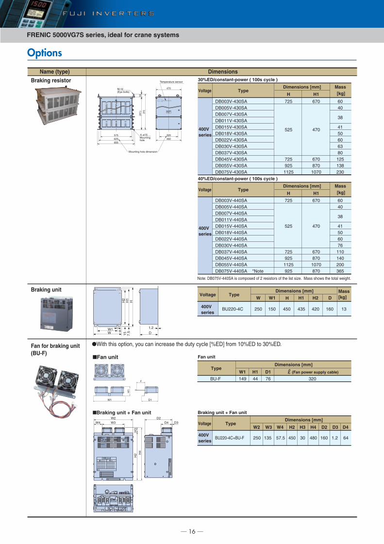
Options
H2
H1
H
W 6W1
15 D
1.2
7.5
Voltage TypeDimensions [mm] Mass
[kg]W W1 H H1 H2 D
400V series
BU220-4C 250 150 450 435 420 160 13
Name (type)
Braking resistor
Braking unit
Fan for braking unit (BU-F)
●With this option, you can increase the duty cycle [%ED] from 10%ED to 30%ED.
Dimensions
■Fan unit
W1
H1
D1
Type
Fan unit
Dimensions [mm]
BU-F 149
W1
44
H1
76
D1
320
(Fan power supply cable)
DBUnitWARNING
■Braking unit + Fan unit
H2
H3
H4
W3W4W2
D4 D3D2
TypeDimensions [mm]
BU220-4C+BU-F 250
W2
135
W3
57.5
W4
450
H2
30
H3
480
H4
160
D2
1.2
D4D3
64400V series
Voltage
Braking unit + Fan unit
TypeDimensions [mm] Mass
[kg]
DB003V-430SADB005V-430SADB007V-430SADB011V-430SADB015V-430SADB018V-430SADB022V-430SADB030V-430SADB037V-430SADB045V-430SADB055V-430SADB075V-430SA
725
525
725925
1125
670
470
670870
1070
6040
38
4150606380125138230
H H1
400V series
Voltage
30%ED/constant-power ( 100s cycle )
TypeDimensions [mm] Mass
[kg]
DB003V-440SADB005V-440SADB007V-440SADB011V-440SADB015V-440SADB018V-440SADB022V-440SADB030V-440SADB037V-440SADB045V-440SADB055V-440SADB075V-440SA *Note
Note: DB075V-440SA is composed of 2 resistors of the list size. Mass shows the total weight.
725
525
725925
1125925
670
470
670870
1070870
6040
38
41506076110140200365
H H1
400V series
Voltage
40%ED/constant-power ( 100s cycle )
575625
320460
655(H
1) (H)
55
470
4-ø15
M-12
Mountinghole
Mounting hole dimension
(Eye bolts)
Temperature sensor
N P
17
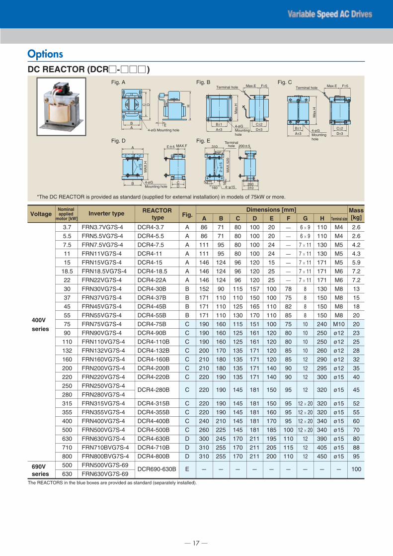
Options
The REACTORS in the blue boxes are provided as standard (separately installed).
DC REACTOR (DCR )
*The DC REACTOR is provided as standard (supplied for external installation) in models of 75kW or more.
Fig. A Fig. B
Fig. D Fig. E
Fig. C
400Vseries
690Vseries
FRN3.7VG7S-4
FRN5.5VG7S-4
FRN7.5VG7S-4
FRN11VG7S-4
FRN15VG7S-4
FRN18.5VG7S-4
FRN22VG7S-4
FRN30VG7S-4
FRN37VG7S-4
FRN45VG7S-4
FRN55VG7S-4
FRN75VG7S-4
FRN90VG7S-4
FRN110VG7S-4
FRN132VG7S-4
FRN160VG7S-4
FRN200VG7S-4
FRN220VG7S-4
FRN250VG7S-4
FRN280VG7S-4
FRN315VG7S-4
FRN355VG7S-4
FRN400VG7S-4
FRN500VG7S-4
FRN630VG7S-4
FRN710BVG7S-4
FRN800BVG7S-4
FRN500VG7S-69
FRN630VG7S-69
DCR4-3.7
DCR4-5.5
DCR4-7.5
DCR4-11
DCR4-15
DCR4-18.5
DCR4-22A
DCR4-30B
DCR4-37B
DCR4-45B
DCR4-55B
DCR4-75B
DCR4-90B
DCR4-110B
DCR4-132B
DCR4-160B
DCR4-200B
DCR4-220B
DCR4-280B
DCR4-315B
DCR4-355B
DCR4-400B
DCR4-500B
DCR4-630B
DCR4-710B
DCR4-800B
DCR690-630B
3.7
5.5
7.5
11
15
18.5
22
30
37
45
55
75
90
110
132
160
200
220
250
280
315
355
400
500
630
710
800
500
630
A
A
A
A
A
A
A
B
B
B
B
C
C
C
C
C
C
C
C
C
C
C
C
D
D
D
E
86
86
111
111
146
146
146
152
171
171
171
190
190
190
200
210
210
220
220
220
220
240
260
300
310
310
—
71
71
95
95
124
124
124
90
110
110
110
160
160
160
170
180
180
190
190
190
190
210
225
245
255
255
—
80
80
80
80
96
96
96
115
110
125
130
115
125
125
135
135
135
135
145
145
145
145
145
170
170
170
—
100
100
100
100
120
120
120
157
150
165
170
151
161
161
171
171
171
171
181
181
181
181
181
211
211
211
—
20
20
24
24
15
25
25
100
100
110
110
100
120
120
120
120
140
140
150
150
160
170
185
195
205
200
—
—
—
— —
—
— —
78
75
82
85
75
80
80
85
85
90
90
95
95
95
95
100
110
115
110
—
6 × 96 × 97 × 11
7 × 11
7 × 11
7 × 11
7 × 11
8
8
8
8
10
10
10
10
12
12
12
12
12 × 20
12 × 20
12 × 20
12 × 20
12
12
12
—
110
110
130
130
171
171
171
130
150
150
150
240
250
250
260
290
295
300
320
320
320
340
340
390
405
450
—
M4
M4
M5
M5
M5
M6
M6
M8
M8
M8
M8
M10
ø12
ø12
ø12
ø12
ø12
ø15
ø15
ø15
ø15
ø15
ø15
ø15
ø15
ø15
—
2.6
2.6
4.2
4.3
5.9
7.2
7.2
13
15
18
20
20
23
25
28
32
35
40
45
52
55
60
70
80
88
95
100
Terminal hole
4-øGMounting hole
B±1
Max
.H
A±3
C±2
Max.E F±5
D±3
Terminal hole
4-øGMounting hole
B±1
Max
.H
A±3
C±2
Max.E F±5
D±3
VoltageNominal applied
motor [kW]
REACTOR type Fig.Inverter type
Dimensions [mm] Mass[kg]A B C D E F G H Terminal size
E
HC D
BA
4-øG Mounting hole
4-øG Mounting hole
B C
MAX.FE±5
D
AM
AX
.Hø
15
160
16
50260310
310
MA
X.5
20
NP
Terminalhole
FRENIC 5000VG7S series, ideal for crane systems
18
Options
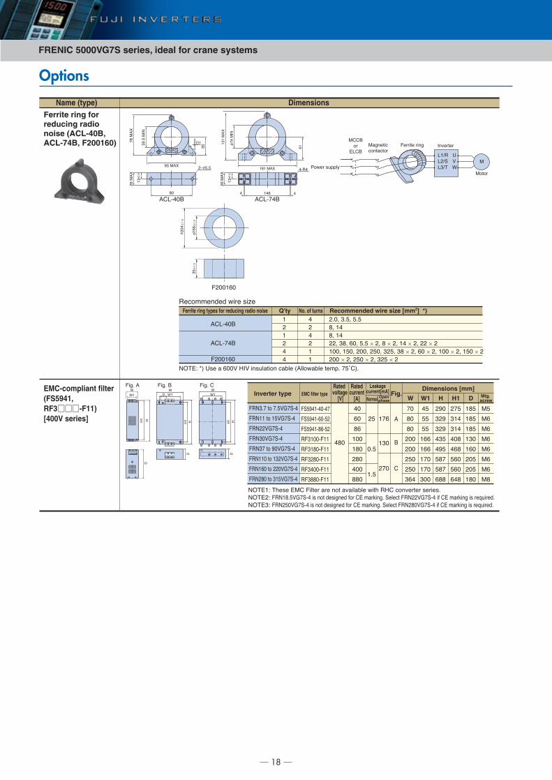
Name (type)
Ferrite ring for reducing radio noise (ACL-40B, ACL-74B, F200160)
EMC-compliant filter (FS5941, RF3 -F11) [400V series]
Dimensions
����������� �� � �
����� �� ��� � ���� ��� �������� ����� !������� ���"# $%&'�#
����(� �)��� �*' +���� ��� ��� �,������ �) ��' ���,����� �����#����-� +��(.#%�/$012 � ��� ���3��� 4�� '� ���5�3# 0����� +��--�/$012 4 '� ���5�3 � ��6����#����7� +��-%��/$012 � ��� ���3��� 4�� '� ���5�3# 0����� +��-.��/$012 4 '� ���5�3 � ��6����#
!'812�9 !'81$29.�
-�
*!
:
(7
;�#7
-1 %#%
*�3�������������
+����� ��3 ��,�����
*����
<��� ��""�=
8(>�8->087>�
��?
*
*''9��
�8'9
(2�2 2
-�
*!
:
(7
;�#7
21�2
��-
@@(
�<
�(
A% *!:
7A#%
*��
7%
$.
*!
:
�<
(.( *!:
$2
*��
�(
(7(
*!
:
�<
Ferrite ring types for reducing radio noise Q'ty No. of turns Recommended wire size [mm2] *)
!'812�9
!'81$29
+-��(��
(
-
(
-
2
2
2
-
2
-
(
(
-#�B 7#%B %#%
.B (2
.B (2
--B 7.B ��B %#% × -B . × -B (2 × -B -- × -(��B (%�B -��B -%�B 7-%B 7. × -B �� × -B (�� × -B (%� × --�� × -B -%� × -B 7-% × -
@
?
��(
@
?(
+3# 9?
��(
@
?(
+3# '
Inverter type EMC filter type Fig.Dimensions [mm]
WNormal Openphase W1 H H1
+0%A2(12�12$
+0%A2(1��1%-
+0%A2(1.�1%-
�+7(��1+((
�+7(.�1+((
�+7-.�1+((
�+72��1+((
�+7..�1+((
2.�
2�C
��C
.�
(��C
(.�C
-.�C
2��C
..�
C
-%C
C
�#%C
C
(#%
($�C
(7�C
C
-$�
!
9
'
+��7#$ �� $#%�/$012
+��(( �� (%�/$012
+��--�/$012
+��7��/$012
+��7$ �� A��/$012
+��((� �� (7-�/$012
+��(�� �� --��/$012
+��-.� �� 7(%�/$012
$�C
.�C
.�C
-��
-��
-%�
-%�
7�2
2%C
%%C
%%C
(��
(��
($�
($�
7��
-A�C
7-AC
7-AC
27%
2A%
%.$
%.$
�..
-$%C
7(2C
7(2
2�.
2�.
%��
%��
�2.
D
(.%C
(.%C
(.%C
(7�
(��
-�%
-�%
(.�
Mtg. screw
*%
*�
*�
*�
*�
*�
*�
*.
Rated voltage
[V]
Ratedcurrent
[A]
Leakagecurrent[mA]
+3# !
�
?(
?
�(
@
+-��(��
-�2±
(#�
(%�±
(#�
7%±
(#�

19
Output circuit filter (OFL- -4A) [400V series]
+��7#$�/$012+��%#%�/$012+��$#%�/$012+��((�/$012+��(%�/$012+��(.#%�/$012+��--�/$012+��7��/$012+��7$�/$012+��2%�/$012+��%%�/$012+��$%�/$012+��A��/$012+��((��/$012+��(7-�/$012+��(���/$012+��-���/$012+��--��/$012+��-%��/$012+��-.��/$012+��7(%�/$012+��7%%�/$012+��2���/$012+��2%��/$012+��%���/$012+���7��/$012+��$(��/$012+��.���/$012
(2
--
7%
2%
(-(%C($C--C-%C-.C7.C2-C2.C��C$�C
$.
A�(��((�(-%(2%
Filter type Fig.Dimensions [mm]
A B C D E F�+817#$12!
�+81$#%12!
�+81(%12!
�+81--12!
�+817�12!�+817$12!�+812%12!�+81%%12!�+81$%12!�+81A�12!�+81((�12!�+81(7-12!�+81(��12!�+81-��12!�+81--�12!
�+81-.�12!
�+817(%12!�+817%%12!�+812��12!�+812%�12!�+81%��12!�+81�7�12!�+81$(�12!�+81.��12!
!
9
'D+
@D+
�D/
--�
-A�
77�
-(�
--�C
CC
-��CCC
7��CC
7-�C72�C
7%�
22�
--%
-A�
-$%
7��
($%C(A�C(A%C-��C
-(�CC
-7�C
-2�CC
-$�C
7��
-$%-A�-A%7-%77%
--�
-7�
7(�
77�
-(�C--�C-�%C-$%C
-A�C
C77�C
72�C
C7%�C7A�C
27�
2%�2.�%(�2$�%��
-��
-��
7��
$�C$%C$�CC
.%CCC
(��CC
(�%C
((%
(%�
((%
(��
(2%
($�
(2�C(%�C(%%C(��C
($�CC
(A�C
-��CC
--�C
-%�
-7�-2%-2�-$�-.�
E
A�CA%C(2�C
(%�C
(%%C
($�C
(.�C
(A�C
-��
($�
($%
(A%-(�
I
E
(��CC
-77
777
E
Groundingscrew
Terminalscrew H
Mountingscrew G
*2
*%
*�
E
*2
*%
*�
�#2CC
.#2CCC
(�#%CCCC
(7
(%
*%
*�
*.
.CC
(�CCCC
(-
(%
��?:FG
@;-
*!: ! *!: 9
�;7
*!
:'
*�����3 )���
/������3
������� �<
������� ����
����3 �<
'����� �<
'������<
��?:FG
@;-
*!: ! *!: 9
�;7
*!
:'
7%
*�����3 )���
/������3
������� �<
������� ����
����3 �<
'����� �<
'������<
@
�1�
�<
�9
+
*!
:#'
(��
21H/
G( G-F( F-:( :-
!
@
�1� �<
�9
+
*!
:#'
21H/
G(
G-
F(
F-
:(
:-
!
●Filter+3# ! +3# 9
+3# ' +3# @
+3# �
+3# /
21H(�
27�
2��
�
7.%
2($
72
7�
●Resistor/capacitor
+3# +
Applicable inverterApprox.
mass[kg]
�)� ��"����� ��� ������� 4�� 4���� �+817�12!�� ���3�� )�,� �� �� �������� ��"������= �)���"����� ��� ������� ������ ��� ���������� � �)� 4���� ���� �� �)� ����� �����#
Options
Name (type) Dimensions
@ �
9!
�<
:( F( G(
*!
:#'
:- F- G-
+
21H/
%%�
%�� �%�
2%� �-�
7�
�<21H(7
'������ �) +�I

������ ������ �� �������� �����
������������� �������������� ��� � � !� ���"�#��
$���% &'��!��'(��' �� )�*% &'��!��'(��'��+
http://www.fujielectric.co.jp/fcs/
,�-.����� �� ���� ������ �� ���/��� � ������ 0����� ������ $.����� �� "�#�� + ��1 2, ��3� 45 �� ! ),�
$.����� � � 6 .������� #�#�.