Embed Size (px)
Citation preview
PRODUCTION PLANNING & CONTROL, 1995, VOL. 6, NO. 1, 69- 79
A production management information model' for discrete manufacturing
S. R. RAY and S. WALLACE
Keywords database, integration, NIAM, tracking
Abstract. The Manufacturing Systems Integration (MSI)project at the National Institute o f Standards and Technologyi s developing a system architecture that incorporates an inte -grated production planning and control environment. T h edevelopment of this architecture includes the definition of infor-mation models describing the information which needs to b eshared among production management systems (productionplanning, scheduling and control systems) in order to achievethe integration of manufacturing systems. This paper presentsthe production management information model within the MSIproject. The main focus of the model i s to identify andcharacterize the relationships between orders and workpieces,to identify the information necessary to achieve workpiecetracking and to identify the information necessary to achieveresource requirements specifications for process plans.
1. Introduction
T h e nature of the state -of-the-art manufacturing shopfloor has undergone many transitions in the last decade.
The dramatic drop in the cost of computer technology i schanging fundamental assumptions which underlaidearlier system designs. Centralized systems, based uponthe need to share the sizeable investment in a single com-
puter, are giving way to distributed systems, enablinglocalized, more reactive implementations. Automation,once seen as a means of increasing repeatability andreducing boredom or hazards, i s no longer a luxury butan economic necessity for the survival of manyindustries.
Many of the early challenges for automation fell underthe classification of robotics research. Information tech -nology, in contrast, was not as much of an issue in themanufacturing domain as it was in business and financial
circles. However, with the increasing levels of automa -tion being introduced in today's manufacturing factories,the need for explicit unambiguous production infor -mation i s rising dramatically. Whereas in the past muchof the complexity of this information was carr ied in the
Authors: S. R. Ray and S. Wallace, Factory Automation Systems Division, ManufacturingEngineering Laboratory, National Ins t i t u te of Standards and Technology, Gaithersburg, MD20899 USA.
STEVEN R. RAY, received h i s B.Sc. in Physics at the University of Bristol in 1977 and hisPh.D. in Mechanical & Aerospace Engineering at Princeton University in 1981. H i s technicalwork concerns the integrated development and handling of manufacturing data used within aproduction facility. While he has worked on information and architectural issues in many phasesof the manufacturing production cycle, his particular focus i s on the advancement of computer -aided process planning research. H e i s the project manager for the Process Planning team atNational Institute of Standards and Technology (NIST) and the founder of the National Testbedfor Process Planning Research located at NIST and funded by the Defense Advanced ResearchProjects Agency (DARPA). H e served as acting chairman of the Initial Graphics ExchangeSpecification -Product Data Exchange using STEP (IGES -PDES) Voluntary Organizationduring 1989-1990, which i s responsible for the ongoing developrnent of both the IGESspecification and the U S effort in support o f the Standard for the Exchange of Product Model Data(International Organization for Standardization, Standard N o I S 0 10303).
SARAH E. WALLACE received her R.A. in Mathematics at Mount Holyoke College in 1988 andh e r M.S. in Computer Science at the University of Maryland in 1990. H e r work involves thedevelopment, specification and prototyping of a system architecture for the integration ofmanufacturing systems on the shop floor. T h i s effort i s part of the Automated ManufacturingResearch Facility project at NIST. She i s a computer scientist providing software engineering andsoftware development expertise- including software design methodologies and computer -aidedsoftware engineering techniques- to the prototyping of manufacturing and information systems.
0953 -7287/95 $10.00 0 1995 Taylor 8; Francis Ltd.

66 S. R. Ray and S. Wallace
manufacturing professional’s head, today’s applicationsrequire all the semantics to be explicitly represented. Themagnitude of this challenge i s perhaps best exemplifiedby the ongoing standardization effort under InternationalOrganization for Standardization? (ISO) TechnicalCommittee (TC) 184-Subcommittee (SC) 4 f known as
the Standard for the Exchange of Product Model Data(STEP) ( I S 0 1992).
All these developments point to the need for in te -
gration of formerly separate manufacturing functionsand emphasize the fact that the nature of informationwhich must be shared by these functions i s extremelycomplex. This paper describes work performed at theNational Inst i tute of Standards and Technology (NIST)in the area of information modelling of production man-agement data in discrete manufacturing enterprises. Inparticular, the reported work addresses some of the infor-mation which must be shared between production plan-ning, scheduling and control functions. Section 2describes the motivation and rationale for defining suchan information model. Section 3 provides some back-ground on NIST and i t s role in manufacturing automa -
tion research. Section 4 presents a brief survey of relatedmodelling efforts. Section 5 presents the actual infor -mation model. Future work planned in this area i sdescribed in Section 5, and conclusions are presented inSection 6.
2. Motivation
Despite the significant progress made in manufac -turing automation research over the past decade, it i snow apparent that integration i s the emerging challengefor today’s factories. Indeed, studies have shown that, by1993, systems integration spending will exceed infor-mation technology spending for hardware, software,communications and service for the U S Government(FED 1992). One reason for this trend i s the lack ofgeneric integration solutions, which then forces manufac -turers to adopt custom non-reusable solutions to theirintegration problems, which tend to be extremelyexpensive.
2.1. Barriers to integration
T h e r e are at least three identifiable barriers to
achieving an integrated production factory. First, most
t TC184 i s titled ‘Industrial AutomatLon Systems and Integration’.
Programming Languages’.SC4 is titled 'Industrial Data and Global Manufacturing
techniques and tools used to assist in the performance ofproduction functions use specialized and often pro-prietary representations for the information used. Theserepresentations often force manufacturing staff to serveas human interfaces between otherwise automatablefunctions, with the concomitant introduction of errors,ambiguity and misinterpretation. T h e second barrier i sthe lack of support by many systems to communicatewith functions outside of their scope, leading to the si tu -
ation sometimes characterized as ‘islands of automation’.This problem i s primarily one of conflicting communi -
cation protocols. Finally, the lack of consensus on anintegrating architecture which describes the behaviour ofthe system as a whole and thereby constrains the behav-iour of supporting subsystems resul ts in subsystemswhich cannot easily be interconnected even by means ofinformation and protocol translators.
T h e solution to this problem has historically been tohire a systems integration company to study a givenfactory and to identify the various representations, proto-cols and business practices in use. Then, usually at con-siderable expense, customized approaches are designedto map representations, to translate protocols and other -wise to knit together whatever systems cannot be dis-pensed with, supplementing them with whateveradditional modules may b e necessary to achieve the levelo f integration desired. This approach could be avoided ifaccepted standards existed to address the problemscommonly encountered by the systems integrators.
2.2. Information modelling as a tool
There are several obstacles, however, which make thedefinition of suitable production management infor-mation standards difficult. One problem lies in the com -plexity of the information being standardized.Traditional methods of standardizing such informa -tion-in t e r m s of textual descriptions or tables-failwhen applied to large, highly interconnected bodies ofsemantic information. I t i s precisely in this area that thefield of information modelling can help. Ni jssen’s Infor -mation Analysis Methodology (NIAM) (Verheijen andVanBekkum 1982) has i t s roots in linguistics and strives
to provide a r ich and yet unambiguous representation offacts (or information). T h e formal practise of informationmodelling as a discipline supports the larger field ofsystems analysis, which encompasses both informationand activity modelling. Modern computer -aided software
engineering (CASE) tools possess both types of modellingcapability, although the information modelling method -ologies used by CASE tools are typically less powerfulthan those such as NIAM.
There are two additional requ i rements for an effective
Production management information model 67
information modelling methodology. First, an importantprocess in the development of information models,partlcularly standard manufacturing information
'1 models, i s consensus building. The modelling method -ology must support easy human communication andinterpretation of a model. In practice, this i s bestaccomplished by means of a graphical depiction of themodel, and thus the methodology should support a
graphical representation. However, the second require -ment for large complex models i s that the representationof the model be computer interpretable. The ability to
compile directly a normative standard informationmodel, using a computer, has proven to be invaluable in
efforts such as the STEP standard mentioned earlier.Using such an approach, data dictionaries, databaseschemas, database access libraries, parsers and reportgenerators can all be generated automatically. Thereforethe graphical representation of semantic informationshould be mappable to some form of computer codewhich can b e compiled.
T h e discipline of information modelling can thus be
thought of as a vital tool for understanding a system,resolving complexity in an unambiguous way, reachingconsensus and ultimately supporting implementation ofthe system, from the information perspective. T h e focusof this paper i s to present the results o f such a modellingeffort in the domain of factory production management,scheduling and control, but not to describe the modellingmethodology itself.
3. National Inst i tute o f Standards and Technology
Manufacturing research at NIST has been dominatedby the Automated Manufacturing Research Facility(AMRF), funded by both the U S Department of Com-merce and the Navy Manufacturing Technology pro-gramme. I t was the AMRF project which launched a
serious programme of manufacturing research at theNIST.
3.1 . The automated manufacturing research facility
T h e AMRF was established in 1981 to serve as a test -
bed factory to support research in measurement tech -
niques and computer interface standards that arerequired for automated machining of parts in small lotsizes. The primary thrust of the project was to establishclear interface specifications and to support modularstructures to allow plug compatibility between systems.This plug compatibility both allows a flexible manufac -turing environment and offers the capability ofincremental automation in existing facilities.
The AMRF was designed around the concept of hier-archical control, where high-level commands were
decomposed into sequences of simpler commands at the
next lower level in the hierarchy. T h e simpler commandswere in turn decomposed at yet lower levels. Protocolswere established to allow command and status infor -mation to flow upwards and downwards in the hierarchy.T h e bulk of data transfer (such as process plans and partmodels) occurred directly with a distributed data admin-istration system. A mechanism was implemented to allowany controller in the AMRF to request or store in-formation in a generic way, regardless of which databasei s being used to hold that information (Libes andRarkmeyer 1988). T h e adoption of such an architec -ture avoided many potential information bottlenecks.Further, by adopting a hierarchical approach, the com-plexity o f a task was reduced to a manageable level foreach controller in the hierarchy. More details on theAMRF can be found in the papers by Simpson et al.
(1992), Furlani et al. (1983), Hocken and Nanzetta(1983), McLean et al. (1983), McLean (1985) andNanzetta (1984).
3.2. The manufacturing systems integration project
In 1990, many of the architectural and communicationconcepts of the AMRF were revisited under the auspicesof the manufacturing systems integration (MSI) project.In particular, attention was focussed on how to addresserror handling and production management in a hier-archical control system. These two topics were under-stood to be closely related, since errors and otherunanticipated events generally affect the productionschedule. Some of the results of the M S I work can b efound in the papers by Senehi (1991a, b) and Ray(1992).
3.3. Manufacturing systems integration project goals
The approach taken within the MSI project was toaddress three principal goals to enable flexible integrationof manufacturing systems. These three goals were thedefinition of an open architecture which supports bothhierarchical control and production management func-tions, the identification or definition of candidate stan-
dard information models needed by all t he functionswithin the scope of the architecture, and the identifica -tion or definition of candidate standard communicationinterfaces among the modules used to carry out the abovefunctions. Thus, rather than attempting to resolve howbest to carry out many of these manufacturing functions,the aim of the M S I project was to specify how to inte -

68 S. R. Ray and S. Wallace
grate these functions. For an overview of the MSIproject, see Senehi et al. (1992).
This paper addresses one part of the second goal,8 namely the definition of a candidate standard production‘ management information model, which structures the
information needed to support the production functionson a factory shop floor. A complete discussion of theinformation models developed as part of the MSI projecthas been given by Barkmeyer et al. (1993).
4. Prior and related work
The challenge of defining the information models to
support manufacturing production i s receivingincreasing attention from the manufacturing researchand development community. Much of this i s due to theincreasingly apparent need for such standardized struc -
tures as a precursor to integrated manufacturing. Unfor -tunately, relatively l i t t le information i s available in thepublic literature describing the detailed informationmodels which have been developed. One of the motiv -
ations of this publication i s to address this situation byplacing th is information model in the public domain.
There i s at least some evidence in the literature that
work i s going on in the information modelling arena,either for i t s own sake or to support the development ofa new manufacturing system or method. Researchers at
the University o f Massachusetts (Ketcham et al. 1988)describe a ‘database -centred modelling environment’which ‘ , .. holds facilities configurations, productionrequirements, and manufacturing parameters that can beaccessed and updated by several planning and control
models’, Talavage and Barash (1977) at Purdue Univer -sity worked on explicitly defining both the ‘systemdescription’ and the ‘status vector’ for a manufacturingenvironment. Canzi et al. (1989) described both a manu-facturing resource categorization and an AND/ORrepresentation for processes, in support of a knowledge -based scheduling system that they developed. Moyneet al. (1989) developed an abstract generic enti ty -relationship information model for process recipe infor-mation flow. Chryssolouris and Gruenig (1988) pub-lished one of the few explicit manufacturing productionmodels, using the IDEFlX methodology (defined inICAM (1985)), with a scope similar to that described inthis paper. We feel that the current work extends theamount o f detail which i s modelled and supportsadditional manufacturing functions such as scheduling,routeing and resource maintenance.
Computer Aided Manufacturing -International, Inc.(CAM -I) i s an international industrial consortium longassociated with the development o f computer integratedmanufacturing (CIM) technology. In the early 1980s,
CAM -I sponsored a research programme now known asthe Intelligent Manufacturing Management Program(IMMP) which also covered some of these areas. Furtherinformation can be found in the report by CAM1 (1985).
In the national and international standards arena, theneed to model manufacturing production information i s
also coming into the spotlight. I S 0 TCI84/SC4/WG8 i sa new Working Group, (WG), colloquially known as ‘In-dustrial Manufacturing Management Data’, The charterof this group i s to address the ‘model, form, and attrib-utes of data exchanged between an industrial manufac -turing company and i t s environment,’ data ‘to be usedby the manufacturing management for the purposes ofmanaging the manufacturing company, ’ and ‘data con-trolling and monitoring the flow of materials within the... company from a manufacturing management view-point’ ( I S 0 1991). T h e work reported in this paper willbe submitted to WG8.
Finally, a number of commercial production manage -ment systems are available, each of which contains somesort of embedded data model to support work and ordertracking, etc. I t i s the hope of the present authors thatultimately a standard model will be adopted by thevarious commercial vendors and thus one of the majorbarriers to plug compatibility between such systems willbe overcome. I t should be noted that a significant frac-tion of the information appearing in the model presentedhere i s already supported in one form or another withinmost commercial production management systems.Thus, for that portion of the information, the adoption of
a standard model would only require a mapping of pre-vious representations to the standard representation,without altering the functionality of the system.
5. T h e manufacturing systems integrationproduction management information model
The intention of the model presented in this paper i sto capture all shared information necessary to supportproduction management functions-order entry, plan-ning (batching, resource allocation and scheduling),factory configuration and control-in the context o f dis-crete part manufacturing. The model attempts to mergethe viewpoints of the functions l isted above to provide aneutral perspective, at least with respect to those func-tions. This section presents a detailed walk through of theproduction management information model that sup-ports the MSI architecture. Each entity i s defined, i t s
attributes are enumerated and defined, and i t s relation -ships with other entities in the model are discussed.
T h e model’s focus on shared information neither pre -cludes the existence of private data that may be necessaryto perform any of the production management functions

Production management information model 69
Figure 1 Shop orders.
/ \
Figure 2. Plans and nodes.
70 S. R. Ray and S. Wallace
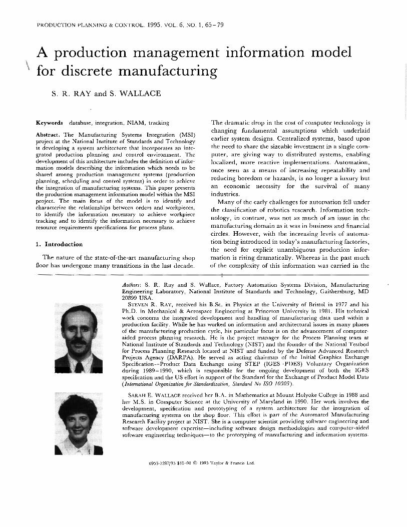
Figure 3. Resources.
f
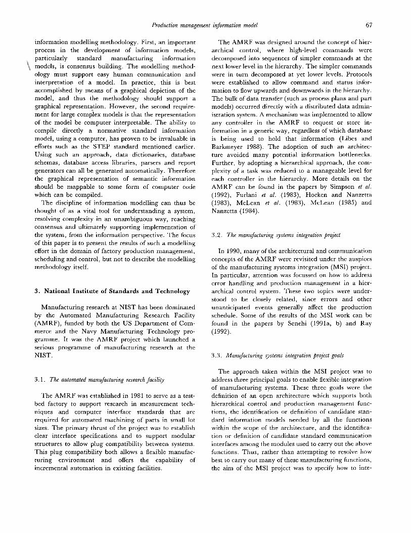
Figure 4. Maintained resources.
Production management information model
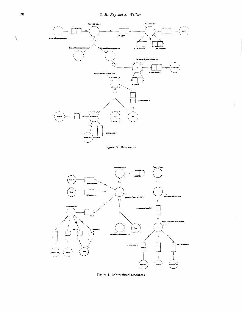
Figure 5. Logical resources.
4
71
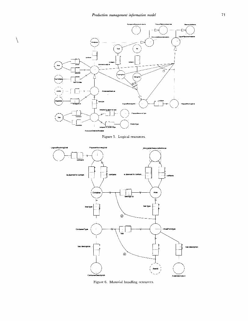
Figure 6. Mater ia l handling resources.
72 S. R. Ray and S. Wallace
nor implies or specifies any policy or procedures on when Table I. Entitles within the production management model.
this information i s generated or used. Section 5.2 dis-sectioncusses a few scenarios describing when and how the
jh, information presented in this information model mightEntity name Relevant figure defined In
be used.Figures 1- 6 depict t he information model using the
NIAM representation. T h e reader i s referred to the
Appendix for assistance in reading NIAM informationmodels. T o aid the reader in correlating the textualdescription of the information model with the NIAM dia-gram, entit ies which appear in the information model are
capitalized (e.g. Shop Order). Table 1 l i s ts each entitycontained in the model, which figure(s) it i s contained in,and what subsection within Section 5.1 defines anddiscusses it.
5.1. Presentation of the manufacturing systems integration
production management information model
The production management information modeladdresses two major areas of production managementinformation requirements: the information necessary forworkpiece tracking, and the information necessary tospecify resource requirements within process plans. As a
result, a large portion of the information model centres
around the attributes of and relationships between ShopOrders, Plans and Nodes, Resources, MaintainedResources, Logical Resources and Material -handlingResources.
5.I.1. Shop Orders
A Shop Order i s any order that causes activity to occur
within a shop; most Shop Orders will cause manufac -turing to occur. There are two types of Shop Order:Internal Shop Orders and External Shop Orders. AnExternal Shop Order i s an order that originates outside
the shop and, as such, has an External Shop OrderSource associated with it. An External Shop OrderSource designates the external entity which causes theexistence of an External Shop Ordcr (e.g. a customer, oranother shop within the factory). An Internal ShopOrder i s an order that originates from either an ExternalShop Order or another Internal Shop Order (e.g. anorder to make a fixture in support o f some other order).T h e information that i s needed for each Shop Order(Internal and External) i s an order identifier to identifyuniquely each order within the shop, the priority of theorder, a due date specifying when that order should b ecompleted, and an earl iest start t ime for initiating theorder. In addition. each Shop Order that causes manu-facturing to occur within the shop needs to specify the
Product Type to manufacture, the quantity to manufac -
AreaArea PrototypeAssemblyContainerContainer TypeControllerEligible Resource SetExternal Shop OrderExternal Shop Order
Generic Production PlanInternal Shop OrderKitKitting UnitLogical Resource InstanceLogical Routeing UnitMaintained Resource
Maintained Resource TypeManufacturing UnitMoveable Resource
NodePermanent Resource
Source
Instance
Instance
InstancePhysical Resource InstancePhysical Kouteing UnitPlanPlan ComplexProcess NodeProcess PlanProduct Type
Production NodeProduction Order UnitProduction Order CTnit
TemplateProduction PlanProduction -managed NodeProduction -managcd PlanResource InstanreResource TypeScheduled Maintenance
OperationSchedule PeriodShop OrderToolTooling Unit
Workpiece
Figure 6Figure 6Figure 3Figure 6Figure 6Figure 3Figure 2F igure 1Figure 1
Figure 2Figure 1Figures 3 and 5Figure 5Figures 3 and 5Figures 5 and 6Figure 4
Figure 4Figure 5Figures 3, 5 and 6
Figure 2Figures 3 - 5
Figures 3 and 5Figures 5 and 6Figures 2Figures 2 and 5Figure 2Figures 1, 2 and 4Figures 1 and 5
Figure 2Figure 5Figure 5
Figure 2Figure 2Figure 2Figures 2- 5Figures 2 - 4Figure 4
Figure 4Figures 1 and 5Figures 3 - 5Figure 5Figures 1, 3 and 5
5.1.65.1.65.1.35.1.65.1.65.1.35.1.25.1.15.1.1
5.1.25.1.15.1.35.1.65.1.55.1.65.1.4
5.1.45.1.55.1.3
5.1.25.1.3
5.1.35.1.65.1.25.1.25.1 .25.1.2
1992)5.1.25.1.55.1.5
5.1.25.1.25.1.25.1.35.1.35.1.4
5.1.45.1.15.1.35.1.65.1.3
(150
ture, and the set of Workpieces (ultimately to becomeFinal Products) associated with the order. I t i s not
necessary (but possible) to associate specific Workpieceswith each Shop Order prior to or during the manufac -turing process; that relationship can be determined after
manufacturing has completed.

Production management information model 73
5.1.2. Plans and Nodes
A Plan i s a recipe for performing a procedure; it con-~itains a set of Nodes (or steps) which provide sequencing
information and detail how to perform each operation.Every Plan has an associated target Resource Typewhich specifies the Resource Instance(s) which mayexecute that Plan. There are three types of Plan: Process
Plans, Production -managed Plans and Production Plans.A Process Plan i s a generic recipe describing how to carryout some procedure in support o f the production of somenumber (usually one) of Products defined by a ProductType. A Production -managed Plan i s an expansion of aProcess Plan which supports the production of a requirednumber of products using a given factory configuration.A Production Plan i s a refinement of a Production -managed Plan which adds resource allocation and sched -uling information. A Plan Complex i s a collection ofProduction -managed or Production Plans, one of whichi s labelled the root Plan; all other Plans in the PlanComplex are referenced directly or indirectly by the root
Plan. In addition, all Plans in a Plan Complex refer tothe same target Resource Instance or Resource Type.
There are three types of Node which parallel the threetypes of Plan: Process Plan Nodes, Production -managedPlan Nodes and Production Plan Nodes. A Process Plancontains only Process Plan Nodes. A Production -managed Plan contains only Production -managed PlanNodes. A Production Plan may contain any combinationof Production -managed Plan Nodes and Production PlanNodes (depending on whether scheduling or reschedulingi s currently being performed). Since a Production Plancontains resource allocation and scheduling information,Production Plan Nodes may have a scheduled start andcompletion time and may refer to specific ResourceInstances.
A Node must detail not only how to perform a specificoperation but also the resources necessary to performthat operation. Any given operation may requireResource Instances with a specific Capability (e.g. three -axis milling), Resource Instances of a specific ResourceType (e. g. three -axis milling machine), specific ResourceInstances (e.g. three -axis milling machine 076X3A), orany combination. Production Plan Nodes necessarilyrefer to Resource Instances since resource allocat~onhasalready been performed. Process Plan Nodes andProduction -managed Plan Nodes refer to some numberof Eligible Resource Sets. T h e number of EligibleResource Sets that are associated with a Node i s the sameas the number of Resource Instances that are to beassociated with the corresponding Production PlanNode; each Eligible Resource Set abstractly or concretelydescribes a single required Resource Instance. An Eli-gible Resource Set may abstractly describe a Resource
Instance by specifying a set of Capabilities, al l of whichthe Resource Instance must satisfy, or by specifying anynumber of Resource Types, at least one of which theResource Instance must be a member of. An EligibleResource Set may concretely describe a ResourceInstance by specifically identifying a set of ResourceInstances, one o f which must be chosen. An EligibleResource Set has a unique identifier and may be referredto by any number of Nodes in any number of Plans.
5.1 .3. Resources
A Resource Instance i s characterized by membershipin some number of Resource Types. T h e modelling ofResource Types i s outside the scope of this paper. A fi rs tstep in characterizing a resource taxonomy and resourceaggregation i s provided via the relationships ‘has sub-types’ and ‘is composed o f (see Figure 3.). Future workwill address a more complete characterization ofResource Types including their behaviour andconstraints.
Each Resource Instance has a universal resource codewhich uniquely identifies it. Resource Instances haveadditional characteristics which may be necessary fornon-production management functions (e.g. processplanning or maintenance); such information i s beyondthe scope of this paper. Resource Instances can be cate-gorized into two major types: Logical Resource Instancesand Physical Resource Instances. Logical ResourceInstances are pieces of information that are created to aidand assist the production management and control func -t ions ; in general, they represent collections of PhysicalResource Instances. All other Resource Instances are
Physical Resource Instances and have some type of
physical realization (e. g. trays, milling machines, sandand electricity). There are two types of PhysicalResource Instance: Permanent Resource Instances andMoveable Resource Instances. Permanent ResourceInstances are either resources that are not expected to
change locations during manufacturing processes (e. g.workstations on the shop floor such as machine tools,fixed robots and storage devices), or resources that do not
require assistance to change their location (e.g. auto-mated guided vehicles, and humans). Some PermanentResource Instances are automated and may have aController associated with them.
Moveable Resource Instances include all PhysicalResource Instances that are not permanent and includesuch resources as Tools, K i t s , Workpieces andAssemblies. Tools are Resource Instances that do not
become part of the Final Product. Kits are groupings ofrelated Tools and Workpieces (e.g. fixtured Workpiece, a
group of Workpieces and the Tools necessary to performa specific operation on those Workpieces). Workpieces

74 S. R. Ray and S. Wallace
are Resource Instances that become part of the FinalProduct. Each Workpiece has status information whichdenotes the state of the Workpiece. This status i s
1 modified by controllers during the manufacturing process‘ i f the Workpiece i s damaged or i t s status i s unknown
(needs to be inspected to determine i t s status).Assemblies are complex Workpieces which are composedof other Workpieces.
5.1.4. Maintained Resources
All Permanent Resource Instances and Tools are alsoMaintained Resource Instances. A Maintained ResourceInstance i s a resource for which availability and mainten -ance information i s needed. For each MaintainedResource Instance, information i s needed about whenthat Resource last underwent maintenance, and howlong that resource has been in service. For example, a
machine tool may have undergone maintenance 2months ago, and i t s time in service (actual processingtime) may be 200 h. Both pieces of information are usefulfor determining when that resource should undergofurther maintenance. For each Maintained ResourceInstance it i s necessary to capture both i t s current andfuture status (classified by ‘reason code’) and the intervalfor which that status i s valid. In the information modelthis i s represented as a Schedule Period. MaintainedResource Instances have a corresponding MaintainedResource Type. A Maintained Resource Type will have
an associated set of Scheduled Maintenance Operations.Each Scheduled Maintenance Operation will specify not
only the type of maintenance that will need to be per -formed on every instance of that type but also an algor -ithm for determining when that type of maintenance will
need to be performed and a Process Plan detailing howto perform the maintenance.
5.1.5. Logical Resources
A Logical Resource Instance i s a piece of informationthat i s created to aid and assist the production manage -ment and control functions. A Logical Resource Instancei s associated with a set of Moveable Resource Instances
that are grouped together during some portion of a
manufacturing process. There are six types of LogicalResource Instance: Manufacturing Units, ProductionOrder Units, Tooling U n i t s , Kitting Units, Logical Rou-teing Units and Physical Routeing Units. LogicalResource Instances may exist for all controllers in acontrol hierarchy.
A Manufacturing Unit i s associated with a set o fWorkpieces that are logically grouped for manufacturingpurposes for some portion of the total manufacturing l i fecycle. Each Manufacturing Unit has a planned and
actual size (number of Workpieces in that Manufac -turing Unit) and refers to each Workpiece instance that
i s contained in the Manufacturing Unit. In addition,each Manufacturing Unit i s associated with a PlanComplex which details, at a given level of control, thesteps to manufacture the planned quantity o f Workpiecesin that Manufacturing Unit.
A Production Order Unit i s a type of ManufacturingUnit and therefore also has a planned and actual size,
refers to each Workpiece instance that i s contained in theProduction Order Unit and i s associated with a PlanComplex which details the steps to manufacture theplanned quantity of Workpieces in that ProductionOrder Unit. In addition, a Production Order Unit .has an
associated priority which i s used during scheduling. Ashop Production Order Unit is, logically, the set o f all
Workpieces of a given Product Type which will betracked as a group throughout i t s entire manufacturingl i fe cycle. A shop Production Order Unit partially orcompletely fulfils one or more Shop Orders.? A workcell (or equipment) Production Order Unit is, logically,the set of all Workpieces of a given Product Type whichwill b e tracked as a group during a contiguous portion ofmanufacturing by a given work cell (or equipment). In
general, the size of Production Order U n i t s and Manu-facturing Uni ts i s constrained by resource capacity (e.g.physical buffer size) of the different machines in thefactory that must operate on the Workpieces contained inthe Production Order U n i t s and Manufacturing Units.Each Production Order Unit has a corresponding Pro-duction Order Unit Template which takes into consider -ation these constraints. A Production Order UnitTemplate exists for each combination of PhysicalResource Type and Product Type. A Production OrderUnit Template specifies the minimum and maximumnumber of Workpieces (of a given Product Type) that aProduction Order Unit (for a given Physical Resource
Type) may contain. Future work will generalize thisconcept to include other resource constraints whichdepend on the Product Type.
5.1.ti. Material -handling resouces
Logical Routeing Units and Physical Routing Unitsrelate to material -handling processes. A Physical Route -
? I t should be notcd that the mapping from Shop Orders (which rep -
resent external tracking of manufacturing requests) and ProductionOrder Units (which represent internal tracking of manufacturingrequests) may include aggregation or disaggregation. In other words,
several Shop Orders may bc fulfilled by the manufacturing of a singleshop Production Order Cnit (aggregation), a single Shop Order ma):
be fulfilled by the manufacturing of several shop Production OrderUnits (disaggregation), or several Shop Orders may be partially fulfilledby the manufacturing of a single shop Production Order Unit (aggre -gat~onand disaggregation).
Production management information model
buffer slze = 8 wldgels
.a o ~ea& 8wdgets and corresponds to0eeShop'srnul - m u .
75
(MHW) buffer size = 4 widget&
-1 --6 eachmnlains 4buffrr SI== IU widgets.poul.puu3 each conlains 8 wuldgeb and c m s p m d Dwk3gel.s (and may addition- the Shop's mu4 - mu9.
piecesInmother Nbsl and
Iml - h 3 .pu4 -pw9eachmnlains4widgets (and may addition-
pieces fmm other Jobs)andeonespmds Lo h e Shop'slm4. LnN.
4 widgets andcnnspmdstoIhe Shop's IrulO. lmlS
ing Unit i s a Logical Resource Instance that representsthe set o f Moveable Resource Instances that make up thecontents o f some Container. T h e Moveable ResourceInstances that the Physical Routeing Unit represent maybe related (i.e. part of the same material -handlingrequest) or not (i.e. not part o f the same material -handling request, but coincidentally collocated). ALogical Routeing Unit is a Logical Resource Instancewhich i s associated with a set of related MoveableResource Instances that are to be routed as a groupthrough some portion of the shop. A Physical RouteingUnit contains one or more Logical Routeing Units anda Logical Routeing Unit i s part o f no more than onePhysical Routeing Unit. For example, a tray (type ofContainer) may contain three widgets and five gadgets.The three widgets may be en route to a specific cleaningand deburring workstation to b e deburred and the five
gadgets may b e en route to the same cleaning and debur-ring machine to be washed. All these workpieces are inthe same tray because it i s convenient for the material -handling system to deliver them to the workstation at thesame time. T h e Physical Routeing Unit i s the collectionof the three widgets and the five gadgets, because all eightMoveable Resource Instances are physically in the trayat the same time. There are two Logical Routeing Uni ts ;the three widgets comprise one Logical Routeing Unitand the five gadgets comprise another Logical RouteingUnit.
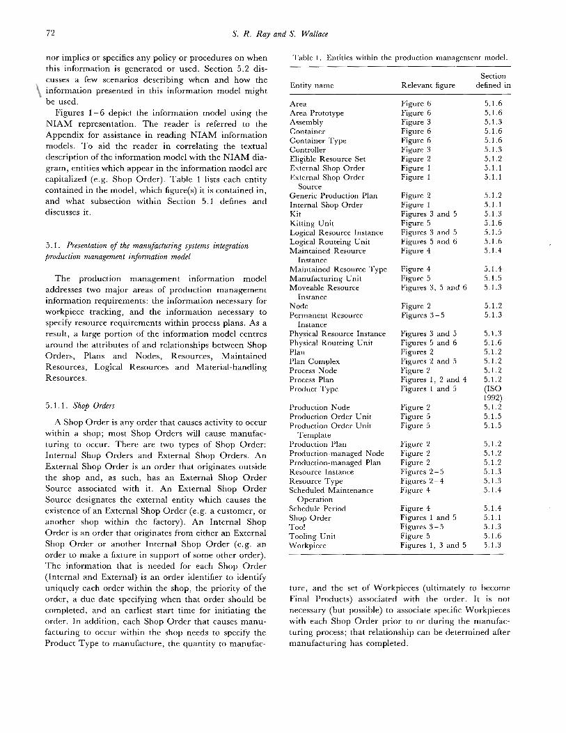
To understand better t he relationships between Pro-duction Order Units, Manufacturing Units and LogicalRouteing Units, consider the following example (Figure7). There i s a Shop Order to make 24 widgets. A widgeti s designed to be a part blank with a hole in the middle.T h e Process Plan for making a single widget contains thefollowing sequence of manufacturing steps: deliver tomill, mill hole, deliver to deburr, deburr hole, anddeliver to inventory. T h e milling work cell has a buffercapacity of eight widgets. T h e deburring work cell has abuffer capacity of four widgets. The material -handlingwork cell uses an automated guided vehicle (AGV), anda tray with a capacity of ten widgets. Given this factoryconfiguration, there will be a single shop ProductionOrder Unit for this Shop Order which will contain the seto f all 24 Workpieces (widgets). Because of the buffercapacity o f the milling work cell, there will b e three shopLogical Routeing Units for the f i r s t material -handlingoperation, each containing eight Workpieces (becausethe material -handling work cell has a capacity greaterthan eight Workpieces, it may choose to put additionalWorkpieces from other jobs on the tray). There will b ethree shop Manufacturing Units for the milling oper-ation, each containing eight Workpieces; each shopManufacturing Unit will correspond exactly to a Produc-tion Order Unit o f the milling work cell. There will be six
J ally conander wmt-
coneJponds 10 h e shop's
ally conmn other work-
po"l0- puis each wnlains
Figure 7. Example of the manufacture of 24 widgets. TheProcess Plan to manufacture one widget i s as follows.
Step 1 Deliver to milling work cell.Step 2 Mill hole.Step 3 Deliver to deburring work cell.Step 4 Deburr hole.Step 5 Deliver to inventory.
shop Logical Routeing Units for the second material -handling operation, each containing four Workpieces(because the material -handling work cell has a capacitygreater than four Workpieces, it may choose to putadditional Workpieces from other jobs on the tray).There will be six shop Manufacturing Units for thedeburring operation, each containing four Workpieces;each shop Manufacturing Unit will correspond exactly toa Production Order Unit of the deburring work cell.There will be six Logical Routeing Units for the final
material -handling operation, each containing fourWorkpieces.
A Tooling Unit i s associated with a set o f Tools whichare required to perform a manufacturing step on at least
one instance of a given Product Type. A Kitting Unit i sassociated with a set of K i t s which are logically groupedtogether for manufacturing purposes for some portion ofthe total manufacturing li fe cycle.
The key to workpiece tracking i s not only knowingwhich Workpieces belong to which Shop Orders, but alsowhere the Workpieces are at all times. Each MoveableResource Instance (e. g. Workpiece) i s logically containedin some Container. Examples of Containers includetrays, robot grippers and machine tool vises. Each Con-tainer i s subdivided into one or more Areas. Each Area
76 S. R. Ray and S. Wallace
1
lower-riaht
Figure 8. Tray 93382 is a Container having a Container Typeof 3 ft by 2 ft Tray.
i s defined to contain no more than a single MoveableResource Instance. The subdivisions of a Container maybe physical or conceptual. For example, a tray may bephysically partitioned to have nine Areas, or it may beconceptually partitioned with no physical barriers. Fur-thermore, a Container may have several different con-
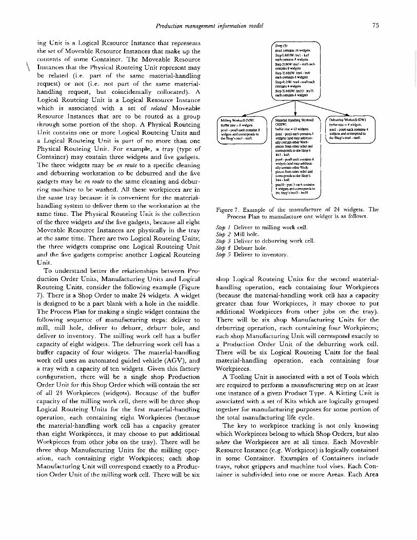
ceptual partitionings. Some Containers may have only asingle Area (e.g. robot gripper). Each Container belongsto a Container Type. Each Container Type i s associatedwith some number of Area Prototypes which identify anddescribe the different partitions of Containers of thattype. A specific Area Prototype of a given ContainerType wil l uniquely identify the corresponding Area of aContainer of that Container Type. For example, there i sa Container Type called a ‘3 ft by 2 ft Tray’ (Figure 8),I t has six associated Area Prototypes, identif ied as fol-lows: upper left, upper middle, upper right, lower left,lower middle and lower right. Tray 93382 i s a 3 ft by 2 ftTray. Therefore it has six Areas, each of which i s iden-tifiable by the Tray and the Area Prototype Identifier.The location of a given Workpiece X could be ‘the upperlef t Area of Tray 93382’.
5.2. Information modelJexibility
Although the production management informationmodel rigidly defines the information that i s sharedbetween production management systems, it remainsflexible by not only allowing organizations to extend theinformation model to incorporate domain specific andpolicy - or procedure -related information but also
allowing the organization to determine when the relation -ships between different entities in the information modelare established.
In particular, this allows flexibility in supportingexternal workpiece tracking (which Workpieces belong to
which Shop Orders). External Workpiece tracking i s
achieved by establishing the relationships between ShopOrders, Production Order U n i t s and Workpieces; whenthese relationships are established determines theaccuracy of external workpiece tracking. Some organiz -
ations requi re that Workpieces always be associated witha Shop Order and that Workpieces cannot switchbetween Shop Orders. In th is case, the relationshipsbetween Shop Orders, Production Order Units andWorkpieces need to be established early in the manufac -
turing li fe cycle and will undergo few, if any, changes.Other organizations may require that Workpieces alwaysbe associated with a Shop Order, but that Workpiecesc a n switch between Shop Orders in order to meet
deadlines. In this case, the relationship between ShopOrders and Production Order Units needs to be estab-lished early in the manufacturing l i fe cycle, but the
relationships between Shop Orders and Workpieces maybe deferred. Other organizations may have absolutely norequirements about tying Workpieces to Shop Ordersduring the manufacturing life cycle but require thatknowledge after the manufacturing i s complete. In thiscase, the relationships between Shop Orders, ProductionOrder U n i t s and Workpieces may be deferred until theend of the manufacturing l i fe cycle, when a Workpiecewould be assigned to a given Shop Order.
6. Future work
T h e production management information model p re -sented in this paper i s an initial attempt at modelling theinformation necessary on the factory shop floor duringmanufacturing. Because of the highly interconnectednature of th is information, however, a few portions onlyof the information model have been identified. These
include the resource class (Resource Type) and instance(Resource Instance) taxonomy, configuration definitionand status information (Controller), design informationneeded during manufacturing (Product Type andProduct Aspect), and a process plan information model(Plan and Node).
The resource class information model will provide a
taxonomy of fixed resources (e.g. the workstations andequipment on the shop floor), moveable resources (e.g.workpieces, tooling and fixtures), raw stock (e.g. partblanks) and logical resource templates (e. g. templates forlogical groupings of physical resources). Informationincluded in this information model will allow for the spe-cification of physical characteristics o f all resource classes
(e.g. dimensions, weight and manufacturer), capabilityinformation needed for process planning, and physicalconstraint information needed for production planningand scheduling (e.g. maximum buffer size, and numberof spindles).
T h e resource instance information model will contain
the resource instance information which differs frominstance to instance (e.g. physical location on the shopfloor for fixed resource instances, location for moveable
Production management information model 77
resource instances, availability information, andremaining l i f e for consumable resource instances).
The process plan information model will contain the'-i
necessary information for specifying process plans,
including support for task decomposition, synchroniza -tion, alternatives, iteration, sequencing, concurrencyand parallelism. Several efforts are currently under wayto develop a process plan information model, includingthe I S 0 process plan model being worked on within I S 0TC184 SC4/WG3/Pll, and ALPS (Catron and Ray1991, Ray 1992).
The configuration definition information model will
contain the information necessary to define a controlhierarchy and static controller information. The con-figuration status information model will contain thecurrent status information about controllers which are inan instantiated control hierarchy.
Some design information i s necessary during manufac -turing, such as geometries, dimensions, shape, weightand tolerance information. This information i s necessaryfor material handling (e.g. dynamic path planning, colli -sion avoidance, and for determining grasp locations andorientations) and quality assurance applications duringmanufacturing (e.g. in-process monitoring, post -processgauging, tolerancing and inspection). The primary effortcurrently addressing this information i s STEP ( I S 01992).
The information modelling effort within the MSIproject i s an ongoing process. Current areas of focusinclude refining ALPS, defining the configuration defini-tion and status information model and integrating bothinto the production management information model.
7. Conclusion
T h e MST production management information modeli s our f i r s t attempt at identifying the information that i s
needed by production management systems (order entry,planning and control). I t s main focus i s identifying andcharacterizing the relationships between orders andworkpieces, identifying the information necessary to
achieve workpiece tracking and identifying the infor -mation necessary to achieve resource requirements spe -cifications for process plans. There i s still much work to
be done in the information modelling of manufacturinginformation in order to achieve a generic solution to theintegration of production management systems and offer
the hope of truly plug-compatible systems.
Acknowledgement
T h e results reported in this paper represent t he collectivework of five individuals who make up the MSI Architec -
ture Committee, and to whom the credit should be given.T h e individuals apart from the two authors, are EdBarkmeyer, M. Kate Senehi and Evan Wallace. Specificdetails of this work can be found in the paper byBarkmeyer et al. (1993).
References
BARKMEYER, E., WALLACE, S., RAY, S., WALLACE, E., andSENEHT, M. K., 1993, Manufacturing systems integration:information models. National Institute of Standards and Tech-nology Interagency Report, to be published (National TechnicalInformation Service, Springfield, VA 22161.)
CAM -I, 1985, Study of conceptual information model for anAFMS-final report. CAM -I Report N o . R-85-FM-02,TechTran, Inc., 6710 Embassy Boulevard, Suite 208, PortRichey, FL 34668).
CANZI, U., GUIDA, G., POLONI, W., and POZZI, S., 1989,CHRONOS -I1 a knowledge -based scheduler for complexmanufacturing environments. Proceedings of the Second Inter-national Conference on Data and Knowledge Systems for Manufac -turing and Enp-ineering, Gaithersburg, MD, 1989 (IEEEComputer Society Press, New York), pp. 76- 83.
CATRON, B., and RAY, S., 1991, ALPS-a language forprocess specification. International Journal of Computer IntegratedManufacturzng, 4(2), 105-113.
CHRYSSOLOURIS, G., and GRUENIG,I.,1988, On a databasedesign for intelligent manufacturing systems. InternationalJournal of Computer Integrated Manufacturing, 1(3), 171-184.
FED, 1992, Federal Computer Week, 6(12), 42 (Federal ComputerWeek Publishing Corporation, Falls Church, VA).
FURLANI, C., KENT, E., BLOOM, H., and MCCLEAN, C.,1983, The Automated Manufacturing Research Facility o fthe National Bureau of Standards. Proceedings of the SummerSimulation Computer Conference, Vancouver, BC, 11-13 July1983 (Simulation Controls, L a Jolla, CA.)..
HOCKEN, R., and NANZETTA, P., 1983, Research in auto-mated manufacturing at NBS. Manufacturing Engineering, 4,91.
ICAM, 1985, Information modeling manual IDEF extended(IDEF1X). Integrated Computer-Aided Manufacturing TechnologyProject Report Priority (6201), (US Air Force Systems Com -mand, Wright -Patterson Air Force Base, OH).
ISO, 1991, Mandate. Documnt N o . I S 0 TC184/SC4/WG8 N1( I S 0 TC184/SC4 Secretariat, Gaithersburg, MD)(IGES -PDES-STEP Administration Office, National Insti-tute of Standards and Technology, Building 220, RoomA127, Gaithersburg, MD 20899).
ISO, 1992, Product data representation and exchange. StandardN o . I S 0 10303-71 ( I S 0 TC184/SC4 Secretariat,Gaithersburg, MD) (IGES-PDES-STEP AdministrationOff ice, National Institute of Standards and Technology,Building 220, Room A127, Gaithersburg, MD 20899).
KETCHAM, M. G., SMITH, J. M., and NNAJIB. O., 1988, Anintegrated data model for C I M planing and control. Proceed -ings of the IEEE International Conference on Computer IntegratedManufacturing, Troy, NY, 1988 (IEEE Computer SocietyPress, New York), pp. 338-342.
LIBES, D., and BARKMEYER, E., 1988, The integrated manu-facturing data administration sytem (1MDAS)-An Over -view. International Journal of Computer Integrated Manufacturing,1(1), 44-49.
78 S. R. Ray and S. Wallace
MCLEAN, C. R., 1985, An architecture for intelligent manu-facturing control. Proceedings of International Computers inEngin-eering Conference and Exhibit, Boston, M A , August 1985(American Society for Mechanical Engineers, N e w York),
MCLEAN, C. R., MITCHELL M., and BARKMEYER, E., 1983,A computing architecture for small batch manufacturing.IEEE Spectrum, May, 59-67.
MOYNE J., MCAFEE, L. JR., and TEOREY, T., 1989, Anapplication of entity -relationship data modelling techniquesto the automated manufacturing process. Proceedings of theSecond International Conference on Data and Knowledge Systems forManufacturing andEngineering, Gaithersburg, MD, 1983 (IEEEComputer Society Press, New York), pp. 206-215.
NANZETTA, P., 1984, Update: NBS Research Facilityaddresses problems in setups for small batch manufacturing.Industrial Engineering, 16(6), 68-73.
RAY, S., 1992, Using the ALPS process plan model. Proceed -ings o j the ASME Manufacturing International Conference, Dallas,TX, March 1992 (American Society for MechanicalEngineers, New York), pp. 365-379.
SENEHI, M. K., BARKMEYER, E., LUCE, M., RAY, S.,WALLACE, E., and WALLACE, S., 1991a, Manufauturingsystems integration initial architecture document. NationalInstitute of Standards and TechnolopV Interagency Report No.
b pp. 391-397.
91-4682 (National Technical Information Service,Springfield, VA 22161).
SENEHI, M. K., WALLACE, S., BARKMEYER, E., RAY, S., andWALLACE, E., 1991b, Manufauturing systems integrationcontrol entity interface document. National Institute of Stan-dards and Technolou Interagency Report N o . 91-4626 (NationalTechnical Information Service, Springfield, VA 22161).
SENEHI, M. K., WALLACE, S., and LUCE, M., 1992, Anarchitecture for manufacturing systems integration. Proceed-ings of the ASME Manufacturing International Conference, Dallas,TX, March 1992 (American Society for MechanicalEngineers, N e w York), pp. 293-303.
SIMPSON, J. A,, HOCKEN, R. J., and ALBUS, J. S., 1982, TheAutomated Manufacturing Research Facility of the NationalBureau of Standards. Journal of Manufacturing Engineering,1, 1.
TALAVAGE, J. J., and BARASH, M. M., 1977, Informationand control in computerized manufacturing systems. InY. 0. Shima (ed.) Proceedings of the International Federation ofAutomatic Control Symposium on Information -Control Problems inManufacturing, Tokyo 1977 (Pergamon, Oxford), pp.
VERHEIJEN, G. M. A,, and VANBEKKUM, J., 1982, NIAM:an information analysis method. Information Systems DesignMethodologies: A Comparative Review (North -Holland,Amsterdam).
279 -293.
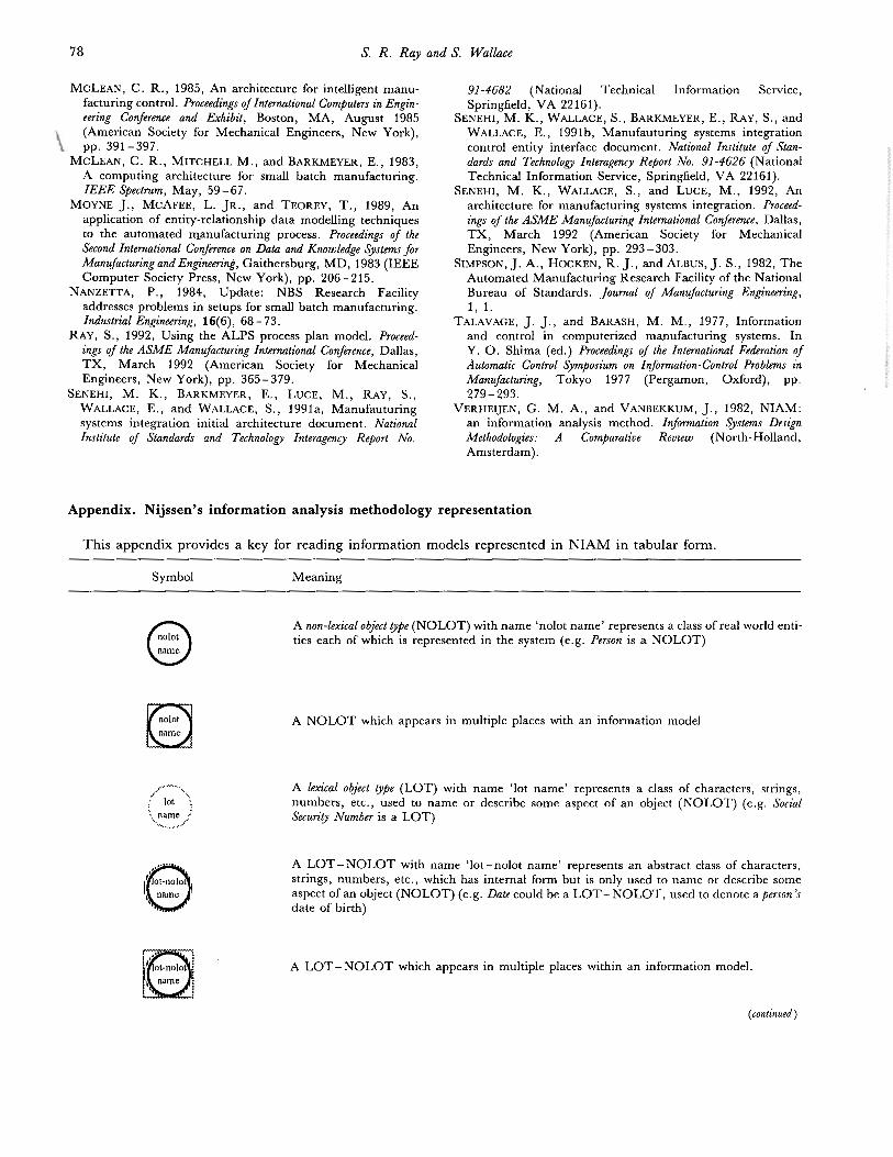
Appendix. Ni jssen’s information analysis methodology representation
This appendix provides a key for reading information models represented in NIAM in tabular form.
Symbol Meaning
w
name
A non-lexical object t rpe (NOLOT) with name ‘nolot name’ represents a class of real world enti -ties each of which i s represented in the system (e.g. Person i s a NOLOT)
A NOLOT which appears in multiple places with an information model
A lexical object gpe (LOT) with name ‘lot name’ represents a class of characters, strings,numbers, etc., used to name or describe some aspect of an object (NOLOT) (e.g. SocialSecurity Number i s a LOT)
A LOT-NOLOT with name ‘lot-nolot name’ represents an abstract class of characters,strings, numbers, etc., which has internal form but i s only used to name or describe someaspect of an object (NOLOT) (e.g. Date could be a LOT-NOLOT, used to denote a person’sdate of birth)
A LOT-NOLOT which appears in multiple places within an information model.
(continued)
Production management information model 79
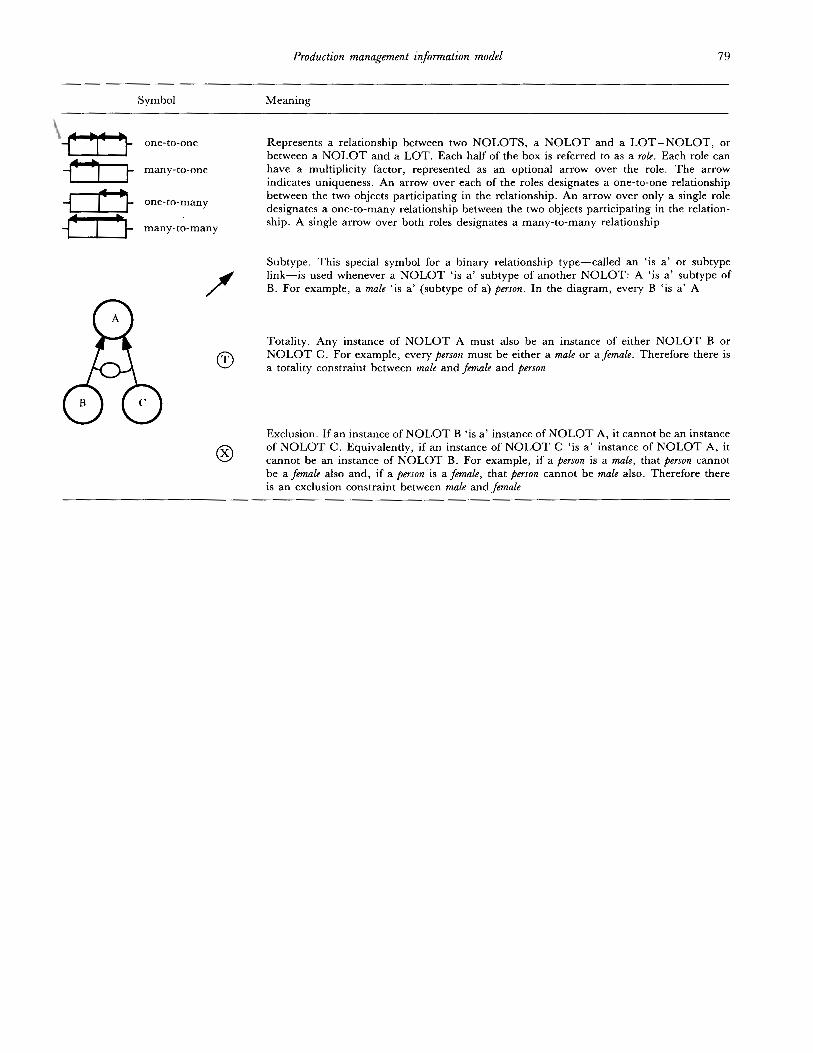
Symbol Meaning
i
one-to-one Represents a relationship between two NOLOTS, a NOLOT and a LOT-NOLOT, orbetween a NOLOT and a LOT. Each half of the box i s referred to as a role. Each role canhave a multiplicity factor, represented as an optional arrow over the role. The arrowindicates uniqueness. An arrow over each of the roles designates a one-to-one relationshipbetween the two objects participating in the relationship. An arrow over only a single roledesignates a one-to-many relationship between the two objects participating in the relation -ship. A single arrow over both roles designates a many -to-many relationship
many-to-one
TI2€33a 3 one-to-many
many -to-many
fSubtype. This special symbol for a binary relationship type-called an ‘ is a’ or subtypelink-is used whenever a NOLOT ‘is a’ subtype of another NOLOT: A ‘is a’ subtype ofB. For example, a male ‘ is a’ (subtype of a) person. In the diagram, every B ‘ is a’ A
Totality. Any instance of NOLOT A must also be an instance of either NOLOT B orNOLOT C. For example, every person must he either a male or ajemak. Therefore there i sa totality constraint between male and female and person
Exclusion. I f an instance of NOLOT B ‘is a’ instance of NOLOT A, it cannot be an instanceof NOLOT C. Equivalently, if an instance of NOLOT C ‘is a’ instance of NOLOT A, itcannot b e an instance of NOLOT B. For example, if a person i s a male, that person cannothe a female also and, if a person i s afemale, that person cannot be male also. Therefore therei s an exclusion constraint between male and female