Embed Size (px)
Citation preview
327
iglidur®
Z
Standard range from stock
Excellent wear resistance especially with
high loads
High thermal resistance
For extreme loads
For high surface speeds
Resistant to edge loads
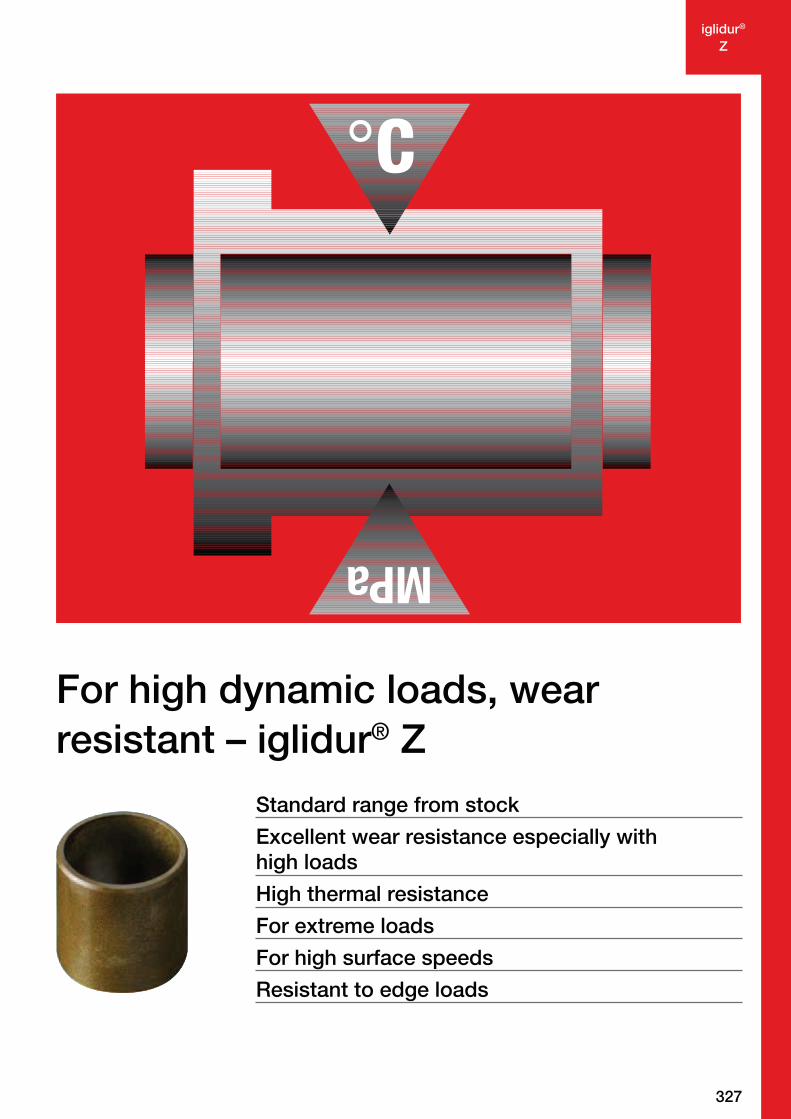
For high dynamic loads, wear
resistant – iglidur® Z
328
iglidur®
Z
–100º
+250º
More information www.igus.eu/eu/z
iglidur® Z
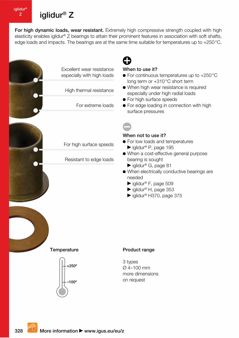
For high dynamic loads, wear resistant. Extremely high compressive strength coupled with high
elasticity enables iglidur® Z bearings to attain their prominent features in association with soft shafts,
edge loads and impacts. The bearings are at the same time suitable for temperatures up to +250 °C.
Excellent wear resistance
especially with high loads
High thermal resistance
For extreme loads
Resistant to edge loads
For high surface speeds
Temperature Product range
3 types
Ø 4–100 mm
more dimensions
on request
When to use it?
For continuous temperatures up to +250 °C
long term or +310 °C short term
When high wear resistance is required
especially under high radial loads
For high surface speeds
For edge loading in connection with high
surface pressures
When not to use it?
For low loads and temperatures
iglidur® P, page 195
When a cost-effective general purpose
bearing is sought
iglidur® G, page 81
When electrically conductive bearings are
needed
iglidur® F, page 509
iglidur® H, page 353
iglidur® H370, page 375

329igus® GmbH Germany | Phone +49 2203 9649-145 Fax -334 | [email protected] | www.igus.eu
iglidur®
Ziglidur® Z | Application Examples
www.igus.eu/hip-jointsystem www.igus.eu/rollercoaster
www.igus.eu/mooring-system www.igus.eu/railroad-platform
Typical sectors of industry
and application areas
Construction machinery
Machine building Textile technology Aerospace engineering
Glass industry etc.
Improve technology and reduce costs –
310 exciting examples for iglidur® plain
bearings online
www.igus.eu/iglidur-applications
330
iglidur®
Z
10.01.00.10.001
0.1
10.0
1,000
1.0
100.0
0.01
Lifetime calculation, CAD files and much more support www.igus.eu/eu/z
iglidur® Z | Technical Data
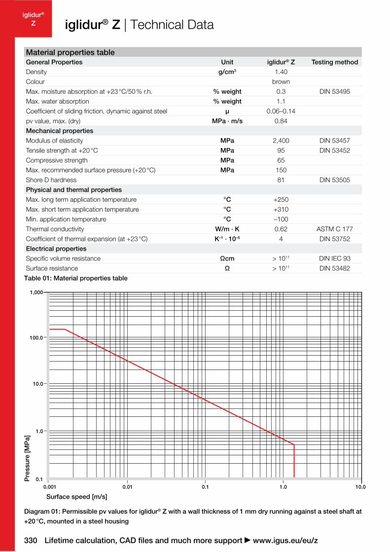
Diagram 01: Permissible pv values for iglidur® Z with a wall thickness of 1 mm dry running against a steel shaft at
+20 °C, mounted in a steel housing
Pressure [MPa]
Surface speed [m/s]
Material properties table
General Properties Unit iglidur® Z Testing method
Density g/cm3 1.40
Colour brown
Max. moisture absorption at +23 °C/50 % r.h. % weight 0.3 DIN 53495
Max. water absorption % weight 1.1
Coefficient of sliding friction, dynamic against steel µ 0.06–0.14
pv value, max. (dry) MPa · m/s 0.84
Mechanical properties
Modulus of elasticity MPa 2,400 DIN 53457
Tensile strength at +20 °C MPa 95 DIN 53452
Compressive strength MPa 65
Max. recommended surface pressure (+20 °C) MPa 150
Shore D hardness 81 DIN 53505
Physical and thermal properties
Max. long term application temperature °C +250
Max. short term application temperature °C +310
Min. application temperature °C –100
Thermal conductivity W/m · K 0.62 ASTM C 177
Coefficient of thermal expansion (at +23 °C) K–1 · 10–5 4 DIN 53752
Electrical properties
Specific volume resistance Ωcm > 1011 DIN IEC 93
Surface resistance Ω > 1011 DIN 53482
Table 01: Material properties table
331igus® GmbH Germany | Phone +49 2203 9649-145 Fax -334 | [email protected] | www.igus.eu
iglidur®
Z
20 50 80 250
0
40
60
100
160
120
120 150 200
140
80
20
1
2
3
4
5
6
7
8
0
0 30 60 90 150120
Diagram 03: Deformation under pressure and temperature
Pressure [MPa] +23 °C +60 °C
0.0
0.5
1.0
1.5
2.5
+23°C +150°C
2.0
Diagram 04: Wear as a function of temperature, rotation
with p = 0.75 MPa, v = 0.5 m/s (CF53 hardened and
ground steel)
Wear [µm/km]
iglidur® Z | Technical Data
In addition to iglidur® X, iglidur® Z is among the best selling
iglidur® high-temperature materials. Specifically worth
noting is the outstanding wear behavior under extreme
conditions (high loads and temperatures).
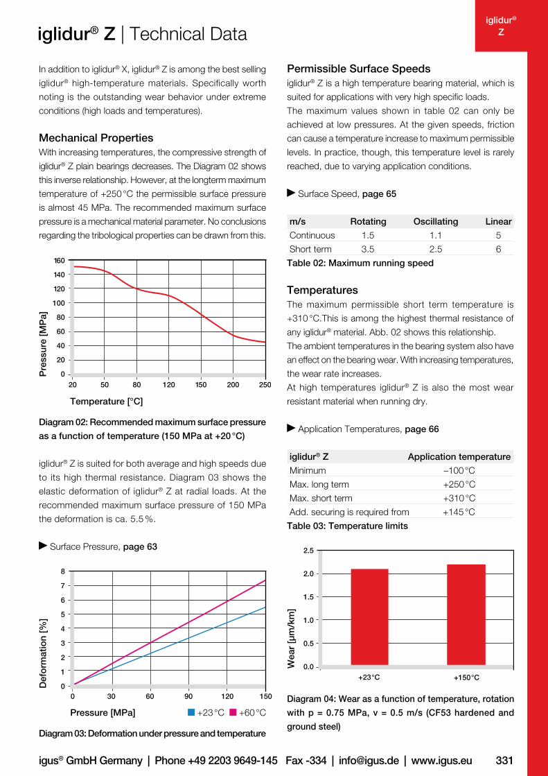
Mechanical Properties
With increasing temperatures, the compressive strength of
iglidur® Z plain bearings decreases. The Diagram 02 shows
this inverse relationship. However, at the longterm maximum
temperature of +250 °C the permissible surface pressure
is almost 45 MPa. The recommended maximum surface
pressure is a mechanical material parameter. No conclusions
regarding the tribological properties can be drawn from this.
iglidur® Z is suited for both average and high speeds due
to its high thermal resistance. Diagram 03 shows the
elastic deformation of iglidur® Z at radial loads. At the
recommended maximum surface pressure of 150 MPa
the deformation is ca. 5.5 %.
Surface Pressure, page 63
Diagram 02: Recommended maximum surface pressure
as a function of temperature (150 MPa at +20 °C)
Pressure [MPa]
Temperature [°C]
Deformation [%]
Permissible Surface Speeds
iglidur® Z is a high temperature bearing material, which is
suited for applications with very high specific loads.
The maximum values shown in table 02 can only be
achieved at low pressures. At the given speeds, friction
can cause a temperature increase to maximum permissible
levels. In practice, though, this temperature level is rarely
reached, due to varying application conditions.
Surface Speed, page 65
m/s Rotating Oscillating Linear
Continuous 1.5 1.1 5
Short term 3.5 2.5 6
Table 02: Maximum running speed
Temperatures
The maximum permissible short term temperature is
+310 °C.This is among the highest thermal resistance of
any iglidur® material. Abb. 02 shows this relationship.
The ambient temperatures in the bearing system also have
an effect on the bearing wear. With increasing temperatures,
the wear rate increases.
At high temperatures iglidur® Z is also the most wear
resistant material when running dry.
Application Temperatures, page 66
iglidur® Z Application temperature
Minimum –100 °C
Max. long term +250 °C
Max. short term +310 °C
Add. securing is required from +145 °C
Table 03: Temperature limits
332
iglidur®
Z
0.1
0.2
0.3
0.1 0.4 1.0 1.3 1.60.70.1
0.2
0.3
0.4
0.05 0.10 0.15 0.20 0.25 0.30 0.35
0.00
0.05
0.10
0.15
0.20
0.25
100 20 30 40 50 60 8070
4.0
8.0
12.0
0.0
2.0
10.0
6.0
Lifetime calculation, CAD files and much more support www.igus.eu/eu/z
iglidur® Z | Technical Data
Shaft roughness Ra [µm]
Coefficient of friction [µ]
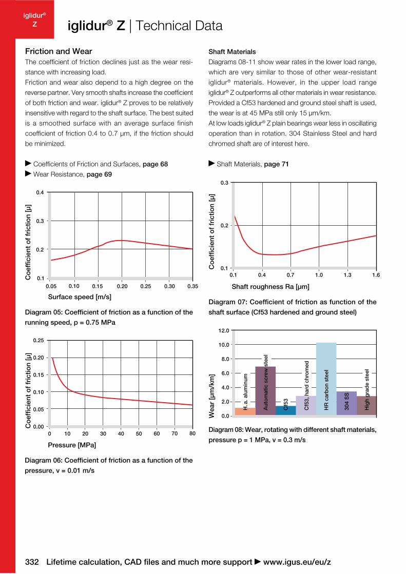
Diagram 07: Coefficient of friction as function of the
shaft surface (Cf53 hardened and ground steel)
Shaft Materials
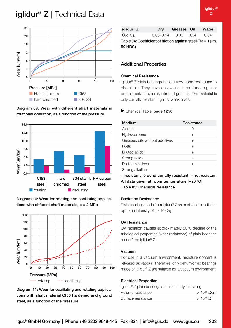
Diagrams 08-11 show wear rates in the lower load range,
which are very similar to those of other wear-resistant
iglidur® materials. However, in the upper load range
iglidur® Z outperforms all other materials in wear resistance.
Provided a Cf53 hardened and ground steel shaft is used,
the wear is at 45 MPa still only 15 µm/km.
At low loads iglidur® Z plain bearings wear less in oscillating
operation than in rotation. 304 Stainless Steel and hard
chromed shaft are of interest here.
Shaft Materials, page 71
Friction and Wear
The coefficient of friction declines just as the wear resi-
stance with increasing load.
Friction and wear also depend to a high degree on the
reverse partner. Very smooth shafts increase the coefficient
of both friction and wear. iglidur® Z proves to be relatively
insensitive with regard to the shaft surface. The best suited
is a smoothed surface with an average surface finish
coefficient of friction 0.4 to 0.7 µm, if the friction should
be minimized.
Coefficients of Friction and Surfaces, page 68
Wear Resistance, page 69
Diagram 05: Coefficient of friction as a function of the
running speed, p = 0.75 MPa
Coefficient of friction [µ]
Surface speed [m/s]
Diagram 06: Coefficient of friction as a function of the
pressure, v = 0.01 m/s
Coefficient of friction [µ]
Pressure [MPa]
Diagram 08: Wear, rotating with different shaft materials,
pressure p = 1 MPa, v = 0.3 m/s
HR carbon steel
304 SS
High grade steel
Wear [µm/km]
Automatic screw steel
H. a. aluminum
Cf53, hard chromed
Cf53
333igus® GmbH Germany | Phone +49 2203 9649-145 Fax -334 | [email protected] | www.igus.eu
iglidur®
Z
0.0
2.5
5.0
7.5
10.0
15.0
12.5
0
4
8
12
16
20
24
201612840
0
20
20 30 40 50 60 70 100100
40
60
80
100
120
140
80 90
iglidur® Z | Technical Data
Pressure [MPa]
rotating oscillating
We
ar
[µm
/km
]
Diagram 11: Wear for oscillating and rotating applica-
tions with shaft material Cf53 hardened and ground
steel, as a function of the pressure
Diagram 10: Wear for rotating and oscillating applica-
tions with different shaft materials, p = 2 MPa
Diagram 09: Wear with different shaft materials in
rotational operation, as a function of the pressure
We
ar
[µm
/km
]
Pressure [MPa]
H. a. aluminum Cf53
hard chromed 304 SS
We
ar
[µm
/km
]
iglidur® Z Dry Greases Oil Water
C. o. f. µ 0.06–0.14 0.09 0.04 0.04
Table 04: Coefficient of friction against steel (Ra = 1 µm,
50 HRC)
Additional Properties
Chemical Resistance
iglidur® Z plain bearings have a very good resistance to
chemicals. They have an excellent resistance against
organic solvents, fuels, oils and greases. The material is
only partially resistant against weak acids.
Chemical Table, page 1258
Medium Resistance
Alcohol 0
Hydrocarbons +
Greases, oils without additives +
Fuels +
Diluted acids +
Strong acids –
Diluted alkalines +
Strong alkalines –
+ resistant 0 conditionally resistant – not resistant
All data given at room temperature [+20 °C]
Table 05: Chemical resistance
Radiation Resistance
Plain bearings made from iglidur® Z are resistant to radiation
up to an intensity of 1 · 105 Gy.
UV Resistance
UV radiation causes approximately 50 % decline of the
tribological properties (wear resistance) of plain bearings
made from iglidur® Z.
Vacuum
For use in a vacuum environment, moisture content is
released as vapour. Therefore, only dehumidified bearings
made of iglidur® Z are suitable for a vacuum environment.
Electrical Properties
iglidur® Z plain bearings are electrically insulating.
Volume resistance > 1011 Ωcm
Surface resistance > 1011 Ω
Cf53
steel
hard
chromed
304 stainl.
steel
HR carbon
steel
rotating oscillating
334
iglidur®
Z
0.00
0.02
0.04
0.06
0.08
0.10
0.0 0.2 0.4 0.6 0.8 1.0 1.2
Lifetime calculation, CAD files and much more support www.igus.eu/eu/z
iglidur® Z | Technical DataReduction of the inner-Ø [%]
Moisture absorption [weight %]
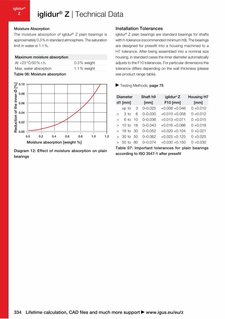
Diagram 12: Effect of moisture absorption on plain
bearings
Moisture Absorption
The moisture absorption of iglidur® Z plain bearings is
approximately 0.3 % in standard atmosphere. The saturation
limit in water is 1.1 %.
Maximum moisture absorption
At +23 °C/50 % r.h. 0.3 % weight
Max. water absorption 1.1 % weight
Table 06: Moisture absorption
Installation Tolerances
iglidur® Z plain bearings are standard bearings for shafts
with h-tolerance (recommended minimum h9). The bearings
are designed for pressfit into a housing machined to a
H7 tolerance. After being assembled into a nominal size
housing, in standard cases the inner diameter automatically
adjusts to the F10 tolerances. For particular dimensions the
tolerance differs depending on the wall thickness (please
see product range table).
Testing Methods, page 75
Diameter Shaft h9 iglidur® Z Housing H7
d1 [mm] [mm] F10 [mm] [mm]
up to 3 0–0.025 +0.006 +0.046 0 +0.010
> 3 to 6 0–0.030 +0.010 +0.058 0 +0.012
> 6 to 10 0–0.036 +0.013 +0.071 0 +0.015
> 10 to 18 0–0.043 +0.016 +0.086 0 +0.018
> 18 to 30 0–0.052 +0.020 +0.104 0 +0.021
> 30 to 50 0–0.062 +0.025 +0.125 0 +0.025
> 50 to 80 0–0.074 +0.030 +0.150 0 +0.030
Table 07: Important tolerances for plain bearings
according to ISO 3547-1 after pressfit
335igus® GmbH Germany | Phone +49 2203 9649-145 Fax -334 | [email protected] | www.igus.eu
iglidur®
Z
30°*
d1
d2
f
b1
30°*
0,5
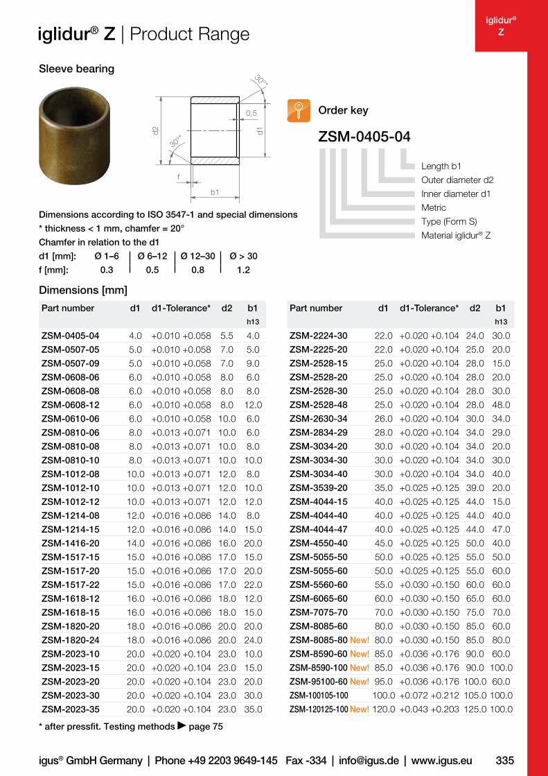
Dimensions according to ISO 3547-1 and special dimensions
* thickness < 1 mm, chamfer = 20°
Chamfer in relation to the d1
d1 [mm]: Ø 1–6 Ø 6–12 Ø 12–30 Ø > 30
f [mm]: 0.3 0.5 0.8 1.2
iglidur® Z | Product Range
Sleeve bearing
ZSM-0405-04
Order key
Length b1
Outer diameter d2
Inner diameter d1
Metric
Type (Form S)
Material iglidur® Z
* after pressfit. Testing methods page 75
Dimensions [mm]
Part number d1 d1-Tolerance* d2 b1
h13
ZSM-0405-04 4.0 +0.010 +0.058 5.5 4.0
ZSM-0507-05 5.0 +0.010 +0.058 7.0 5.0
ZSM-0507-09 5.0 +0.010 +0.058 7.0 9.0
ZSM-0608-06 6.0 +0.010 +0.058 8.0 6.0
ZSM-0608-08 6.0 +0.010 +0.058 8.0 8.0
ZSM-0608-12 6.0 +0.010 +0.058 8.0 12.0
ZSM-0610-06 6.0 +0.010 +0.058 10.0 6.0
ZSM-0810-06 8.0 +0.013 +0.071 10.0 6.0
ZSM-0810-08 8.0 +0.013 +0.071 10.0 8.0
ZSM-0810-10 8.0 +0.013 +0.071 10.0 10.0
ZSM-1012-08 10.0 +0.013 +0.071 12.0 8.0
ZSM-1012-10 10.0 +0.013 +0.071 12.0 10.0
ZSM-1012-12 10.0 +0.013 +0.071 12.0 12.0
ZSM-1214-08 12.0 +0.016 +0.086 14.0 8.0
ZSM-1214-15 12.0 +0.016 +0.086 14.0 15.0
ZSM-1416-20 14.0 +0.016 +0.086 16.0 20.0
ZSM-1517-15 15.0 +0.016 +0.086 17.0 15.0
ZSM-1517-20 15.0 +0.016 +0.086 17.0 20.0
ZSM-1517-22 15.0 +0.016 +0.086 17.0 22.0
ZSM-1618-12 16.0 +0.016 +0.086 18.0 12.0
ZSM-1618-15 16.0 +0.016 +0.086 18.0 15.0
ZSM-1820-20 18.0 +0.016 +0.086 20.0 20.0
ZSM-1820-24 18.0 +0.016 +0.086 20.0 24.0
ZSM-2023-10 20.0 +0.020 +0.104 23.0 10.0
ZSM-2023-15 20.0 +0.020 +0.104 23.0 15.0
ZSM-2023-20 20.0 +0.020 +0.104 23.0 20.0
ZSM-2023-30 20.0 +0.020 +0.104 23.0 30.0
ZSM-2023-35 20.0 +0.020 +0.104 23.0 35.0
Part number d1 d1-Tolerance* d2 b1
h13
ZSM-2224-30 22.0 +0.020 +0.104 24.0 30.0
ZSM-2225-20 22.0 +0.020 +0.104 25.0 20.0
ZSM-2528-15 25.0 +0.020 +0.104 28.0 15.0
ZSM-2528-20 25.0 +0.020 +0.104 28.0 20.0
ZSM-2528-30 25.0 +0.020 +0.104 28.0 30.0
ZSM-2528-48 25.0 +0.020 +0.104 28.0 48.0
ZSM-2630-34 26.0 +0.020 +0.104 30.0 34.0
ZSM-2834-29 28.0 +0.020 +0.104 34.0 29.0
ZSM-3034-20 30.0 +0.020 +0.104 34.0 20.0
ZSM-3034-30 30.0 +0.020 +0.104 34.0 30.0
ZSM-3034-40 30.0 +0.020 +0.104 34.0 40.0
ZSM-3539-20 35.0 +0.025 +0.125 39.0 20.0
ZSM-4044-15 40.0 +0.025 +0.125 44.0 15.0
ZSM-4044-40 40.0 +0.025 +0.125 44.0 40.0
ZSM-4044-47 40.0 +0.025 +0.125 44.0 47.0
ZSM-4550-40 45.0 +0.025 +0.125 50.0 40.0
ZSM-5055-50 50.0 +0.025 +0.125 55.0 50.0
ZSM-5055-60 50.0 +0.025 +0.125 55.0 60.0
ZSM-5560-60 55.0 +0.030 +0.150 60.0 60.0
ZSM-6065-60 60.0 +0.030 +0.150 65.0 60.0
ZSM-7075-70 70.0 +0.030 +0.150 75.0 70.0
ZSM-8085-60 80.0 +0.030 +0.150 85.0 60.0
ZSM-8085-80 New! 80.0 +0.030 +0.150 85.0 80.0
ZSM-8590-60 New! 85.0 +0.036 +0.176 90.0 60.0
ZSM-8590-100 New! 85.0 +0.036 +0.176 90.0 100.0
ZSM-95100-60 New! 95.0 +0.036 +0.176 100.0 60.0
ZSM-100105-100 100.0 +0.072 +0.212 105.0 100.0
ZSM-120125-100 New! 120.0 +0.043 +0.203 125.0 100.0
336
iglidur®
Z
price list online
www.igus.eu/eu/z
delivery
time
prices from stock
d2
30°*
f
b1
b2
d1
d3
r
r = max.
0.5 mm
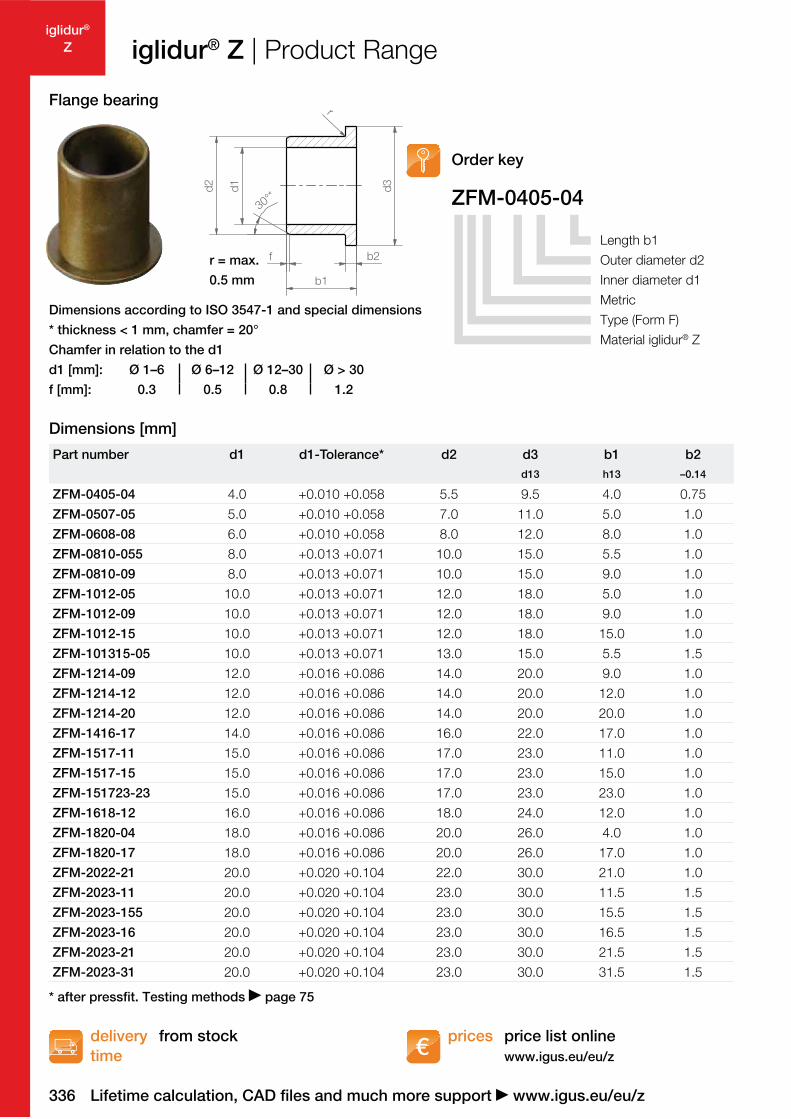
Dimensions according to ISO 3547-1 and special dimensions
* thickness < 1 mm, chamfer = 20°
Chamfer in relation to the d1
d1 [mm]: Ø 1–6 Ø 6–12 Ø 12–30 Ø > 30
f [mm]: 0.3 0.5 0.8 1.2
Part number d1 d1-Tolerance* d2 d3 b1 b2
d13 h13 –0.14
ZFM-0405-04 4.0 +0.010 +0.058 5.5 9.5 4.0 0.75
ZFM-0507-05 5.0 +0.010 +0.058 7.0 11.0 5.0 1.0
ZFM-0608-08 6.0 +0.010 +0.058 8.0 12.0 8.0 1.0
ZFM-0810-055 8.0 +0.013 +0.071 10.0 15.0 5.5 1.0
ZFM-0810-09 8.0 +0.013 +0.071 10.0 15.0 9.0 1.0
ZFM-1012-05 10.0 +0.013 +0.071 12.0 18.0 5.0 1.0
ZFM-1012-09 10.0 +0.013 +0.071 12.0 18.0 9.0 1.0
ZFM-1012-15 10.0 +0.013 +0.071 12.0 18.0 15.0 1.0
ZFM-101315-05 10.0 +0.013 +0.071 13.0 15.0 5.5 1.5
ZFM-1214-09 12.0 +0.016 +0.086 14.0 20.0 9.0 1.0
ZFM-1214-12 12.0 +0.016 +0.086 14.0 20.0 12.0 1.0
ZFM-1214-20 12.0 +0.016 +0.086 14.0 20.0 20.0 1.0
ZFM-1416-17 14.0 +0.016 +0.086 16.0 22.0 17.0 1.0
ZFM-1517-11 15.0 +0.016 +0.086 17.0 23.0 11.0 1.0
ZFM-1517-15 15.0 +0.016 +0.086 17.0 23.0 15.0 1.0
ZFM-151723-23 15.0 +0.016 +0.086 17.0 23.0 23.0 1.0
ZFM-1618-12 16.0 +0.016 +0.086 18.0 24.0 12.0 1.0
ZFM-1820-04 18.0 +0.016 +0.086 20.0 26.0 4.0 1.0
ZFM-1820-17 18.0 +0.016 +0.086 20.0 26.0 17.0 1.0
ZFM-2022-21 20.0 +0.020 +0.104 22.0 30.0 21.0 1.0
ZFM-2023-11 20.0 +0.020 +0.104 23.0 30.0 11.5 1.5
ZFM-2023-155 20.0 +0.020 +0.104 23.0 30.0 15.5 1.5
ZFM-2023-16 20.0 +0.020 +0.104 23.0 30.0 16.5 1.5
ZFM-2023-21 20.0 +0.020 +0.104 23.0 30.0 21.5 1.5
ZFM-2023-31 20.0 +0.020 +0.104 23.0 30.0 31.5 1.5
* after pressfit. Testing methods page 75
Lifetime calculation, CAD files and much more support www.igus.eu/eu/z
iglidur® Z | Product Range
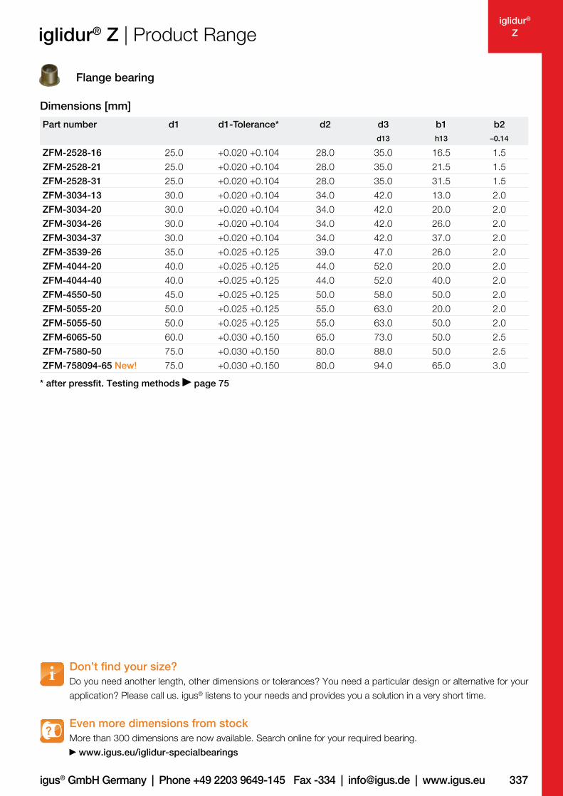
Flange bearing
ZFM-0405-04
Order key
Length b1
Outer diameter d2
Inner diameter d1
Metric
Type (Form F)
Material iglidur® Z
Dimensions [mm]
337igus® GmbH Germany | Phone +49 2203 9649-145 Fax -334 | [email protected] | www.igus.eu
iglidur®
Z
Dimensions [mm]
Part number d1 d1-Tolerance* d2 d3 b1 b2
d13 h13 –0.14
ZFM-2528-16 25.0 +0.020 +0.104 28.0 35.0 16.5 1.5
ZFM-2528-21 25.0 +0.020 +0.104 28.0 35.0 21.5 1.5
ZFM-2528-31 25.0 +0.020 +0.104 28.0 35.0 31.5 1.5
ZFM-3034-13 30.0 +0.020 +0.104 34.0 42.0 13.0 2.0
ZFM-3034-20 30.0 +0.020 +0.104 34.0 42.0 20.0 2.0
ZFM-3034-26 30.0 +0.020 +0.104 34.0 42.0 26.0 2.0
ZFM-3034-37 30.0 +0.020 +0.104 34.0 42.0 37.0 2.0
ZFM-3539-26 35.0 +0.025 +0.125 39.0 47.0 26.0 2.0
ZFM-4044-20 40.0 +0.025 +0.125 44.0 52.0 20.0 2.0
ZFM-4044-40 40.0 +0.025 +0.125 44.0 52.0 40.0 2.0
ZFM-4550-50 45.0 +0.025 +0.125 50.0 58.0 50.0 2.0
ZFM-5055-20 50.0 +0.025 +0.125 55.0 63.0 20.0 2.0
ZFM-5055-50 50.0 +0.025 +0.125 55.0 63.0 50.0 2.0
ZFM-6065-50 60.0 +0.030 +0.150 65.0 73.0 50.0 2.5
ZFM-7580-50 75.0 +0.030 +0.150 80.0 88.0 50.0 2.5
ZFM-758094-65 New! 75.0 +0.030 +0.150 80.0 94.0 65.0 3.0
* after pressfit. Testing methods page 75
Don’t find your size?
Do you need another length, other dimensions or tolerances? You need a particular design or alternative for your
application? Please call us. igus® listens to your needs and provides you a solution in a very short time.
Even more dimensions from stock
More than 300 dimensions are now available. Search online for your required bearing.
www.igus.eu/iglidur-specialbearings
?
iglidur® Z | Product Range
Flange bearing
338
iglidur®
Z
price list online
www.igus.eu/eu/z
delivery
time
prices from stock
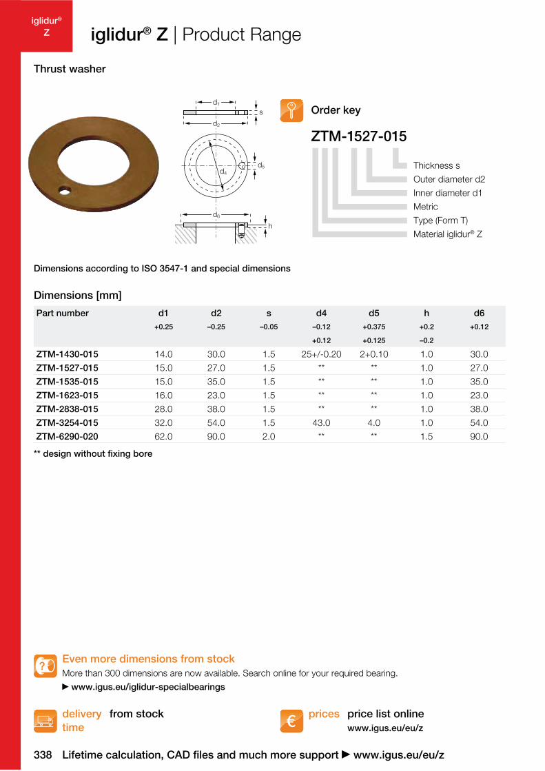
ZTM-1527-015
d5
d1
d2
d4
d6
h
s
** design without fixing bore
Even more dimensions from stock
More than 300 dimensions are now available. Search online for your required bearing.
www.igus.eu/iglidur-specialbearings
?
Part number d1 d2 s d4 d5 h d6
+0.25 –0.25 –0.05 –0.12 +0.375 +0.2 +0.12
+0.12 +0.125 –0.2
ZTM-1430-015 14.0 30.0 1.5 25+/-0.20 2+0.10 1.0 30.0
ZTM-1527-015 15.0 27.0 1.5 ** ** 1.0 27.0
ZTM-1535-015 15.0 35.0 1.5 ** ** 1.0 35.0
ZTM-1623-015 16.0 23.0 1.5 ** ** 1.0 23.0
ZTM-2838-015 28.0 38.0 1.5 ** ** 1.0 38.0
ZTM-3254-015 32.0 54.0 1.5 43.0 4.0 1.0 54.0
ZTM-6290-020 62.0 90.0 2.0 ** ** 1.5 90.0
Lifetime calculation, CAD files and much more support www.igus.eu/eu/z
iglidur® Z | Product Range
Thrust washer
Order key
Thickness s
Outer diameter d2
Inner diameter d1
Metric
Type (Form T)
Material iglidur® Z
Dimensions according to ISO 3547-1 and special dimensions
Dimensions [mm]
339igus® GmbH Germany | Phone +49 2203 9649-145 Fax -334 | [email protected] | www.igus.eu
iglidur®
Z
price list online
www.igus.eu/eu/z
delivery
time
prices from stock
30°
d1
d2
f
b1
30°
0,5
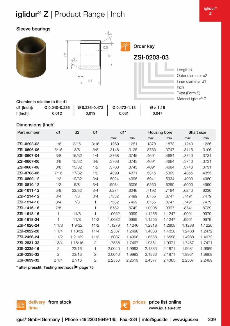
* after pressfit. Testing methods page 75
Part number d1 d2 b1 d1* Housing bore Shaft size
max. min. max. min. max. min.
ZSI-0203-03 1/8 3/16 3/16 .1269 .1251 .1878 .1873 .1243 .1236
ZSI-0506-06 5/16 3/8 3/8 .3148 .3125 .3753 .3747 .3115 .3106
ZSI-0607-04 3/8 15/32 1/4 .3768 .3745 .4691 .4684 .3740 .3731
ZSI-0607-06 3/8 15/32 3/8 .3768 .3745 .4691 .4684 .3740 .3731
ZSI-0607-08 3/8 15/32 1/2 .3768 .3745 .4691 .4684 .3740 .3731
ZSI-0708-08 7/16 17/32 1/2 .4399 .4371 .5316 .5309 .4365 .4355
ZSI-0809-12 1/2 19/32 3/4 .5024 .4996 .5941 .5934 .4990 .4980
ZSI-0810-12 1/2 5/8 3/4 .5034 .5006 .6260 .6250 .5000 .4990
ZSI-1011-12 5/8 23/32 3/4 .6274 .6246 .7192 .7184 .6240 .6230
ZSI-1214-12 3/4 7/8 3/4 .7532 .7499 .8755 .8747 .7491 .7479
ZSI-1214-16 3/4 7/8 1 .7532 .7499 .8755 .8747 .7491 .7479
ZSI-1416-16 7/8 1 1 .8782 .8749 1.0005 .9997 .8741 .8729
ZSI-1618-16 1 11/8 1 1.0032 .9999 1.1255 1.1247 .9991 .9979
ZSI-1618-24 1 11/8 11/2 1.0032 .9999 1.1255 1.1247 .9991 .9979
ZSI-1820-24 1 1/8 1 9/32 11/2 1.1279 1.1246 1.2818 1.2808 1.1238 1.1226
ZSI-2022-20 1 1/4 1 13/32 11/4 1.2537 1.2498 1.4068 1.4058 1.2488 1.2472
ZSI-2426-24 1 1/2 1 21/32 11/2 1.5037 1.4998 1.6568 1.6558 1.4988 1.4972
ZSI-2831-32 1 3/4 1 15/16 2 1.7536 1.7497 1.9381 1.9371 1.7487 1.7471
ZSI-3235-16 2 23/16 1 2.0040 1.9993 2.1883 2.1871 1.9981 1.9969
ZSI-3235-32 2 23/16 2 2.0040 1.9993 2.1883 2.1871 1.9981 1.9969
ZSI-3639-32 2 1/4 27/16 2 2.2556 2.2519 2.4377 2.4365 2.2507 2.2489
d1 [Inch]: Ø 0.040–0.236 Ø 0.236–0.472 Ø 0.472–1.18 Ø > 1.18
f [Inch]: 0.012 0.019 0.031 0.047
Chamfer in relation to the d1
Order key
iglidur® Z | Product Range | Inch
Dimensions [Inch]
ZSI-0203-03
Length b1
Outer diameter d2
Inner diameter d1
Inch
Type (Form S)
Material iglidur® Z
Sleeve bearings
340
iglidur®
Z
price list online
www.igus.eu/eu/z
delivery
time
prices from stock
d2
30°
f
b1
b2
d1
d3
r
r = max.
0.5 mm
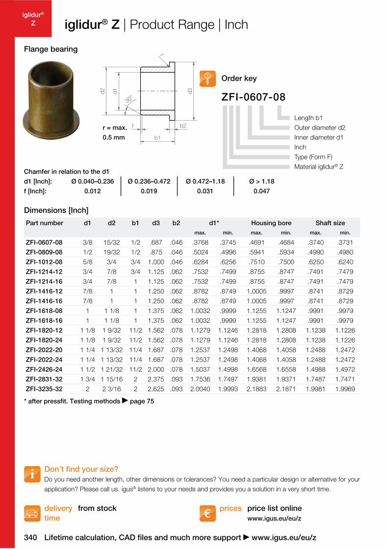
* after pressfit. Testing methods page 75
ZFI-0607-08
Part number d1 d2 b1 d3 b2 d1* Housing bore Shaft size
max. min. max. min. max. min.
ZFI-0607-08 3/8 15/32 1/2 .687 .046 .3768 .3745 .4691 .4684 .3740 .3731
ZFI-0809-08 1/2 19/32 1/2 .875 .046 .5024 .4996 .5941 .5934 .4990 .4980
ZFI-1012-08 5/8 3/4 3/4 1.000 .046 .6284 .6256 .7510 .7500 .6250 .6240
ZFI-1214-12 3/4 7/8 3/4 1.125 .062 .7532 .7499 .8755 .8747 .7491 .7479
ZFI-1214-16 3/4 7/8 1 1.125 .062 .7532 .7499 .8755 .8747 .7491 .7479
ZFI-1416-12 7/8 1 1 1.250 .062 .8782 .8749 1.0005 .9997 .8741 .8729
ZFI-1416-16 7/8 1 1 1.250 .062 .8782 .8749 1.0005 .9997 .8741 .8729
ZFI-1618-08 1 1 1/8 1 1.375 .062 1.0032 .9999 1.1255 1.1247 .9991 .9979
ZFI-1618-16 1 1 1/8 1 1.375 .062 1.0032 .9999 1.1255 1.1247 .9991 .9979
ZFI-1820-12 1 1/8 1 9/32 11/2 1.562 .078 1.1279 1.1246 1.2818 1.2808 1.1238 1.1226
ZFI-1820-24 1 1/8 1 9/32 11/2 1.562 .078 1.1279 1.1246 1.2818 1.2808 1.1238 1.1226
ZFI-2022-20 1 1/4 1 13/32 11/4 1.687 .078 1.2537 1.2498 1.4068 1.4058 1.2488 1.2472
ZFI-2022-24 1 1/4 1 13/32 11/4 1.687 .078 1.2537 1.2498 1.4068 1.4058 1.2488 1.2472
ZFI-2426-24 1 1/2 1 21/32 11/2 2.000 .078 1.5037 1.4998 1.6568 1.6558 1.4988 1.4972
ZFI-2831-32 1 3/4 1 15/16 2 2.375 .093 1.7536 1.7497 1.9381 1.9371 1.7487 1.7471
ZFI-3235-32 2 2 3/16 2 2.625 .093 2.0040 1.9993 2.1883 2.1871 1.9981 1.9969
Don’t find your size?
Do you need another length, other dimensions or tolerances? You need a particular design or alternative for your
application? Please call us. igus® listens to your needs and provides you a solution in a very short time.
Chamfer in relation to the d1
d1 [Inch]: Ø 0.040–0.236 Ø 0.236–0.472 Ø 0.472–1.18 Ø > 1.18
f [Inch]: 0.012 0.019 0.031 0.047
Lifetime calculation, CAD files and much more support www.igus.eu/eu/z
Order key
iglidur® Z | Product Range | Inch
Dimensions [Inch]
Length b1
Outer diameter d2
Inner diameter d1
Inch
Type (Form F)
Material iglidur® Z
Flange bearing


![Gleitlager weltweit vielseitig im Dauerbetrieb auch für ... · PDF file59 iglidur® Flächenpressung [MPa] 0 20 40 60 80 100 120 140 160 iglidur® G iglidur® J iglidur® M250 iglidur®](https://img.pdfslide.net/doc/110x75/5a78dff17f8b9a5a148d014f/-gleitlager-weltweit-vielseitig-im-dauerbetrieb-auch-fr-iglidur-flchenpressung.jpg)