Embed Size (px)
Citation preview
User’s Manual For
MA860H High Performance Microstepping Driver
Version 1.0
.2011 All Rights Reserved
Attention: Please read this manual carefully before using the driver!
Easy Commercial Global Technology Co., LTD
*** Savebase ***

M542H Microstepping Driver Manual V1.0 ----SSAAVVEEBBAASSEE
Email: [email protected] Web: http://stores.ebay.co.uk/SAVEBASE 1
ECG Safety Statement
Easy Commercial Global is not liable or responsible for any accidents, injuries, equipment damage,
property damage, loss of money or loss of time resulting from improper use of electrical or mechanical
or software products sold on this website or other Easy Commercial Global sales resources.
Since Easy Commercial Global basically provide OEM machine builders components to build their
machines for their own use or third party use it is their responsibility to maintain certify and comply the
end user products built base on our components sold on this website or other Easy Commercial
Global sales resources.
Assembling electrical CNC machine component like power supplies, motors, drivers or other electrical
components involve dealing with high voltage like AC alternative current or DC direct current which is
extremely dangerous and need high attention & essential experience and knowledge of software,
electricity, electro-mechanics & or mechanics.
For technical questions please contact us at [email protected] before purchase.
2011 Easy Commercial Global Technology Corporation Limited
All Rights Reserved
M542H Microstepping Driver Manual V1.0 ----SSAAVVEEBBAASSEE
Email: [email protected] Web: http://stores.ebay.co.uk/SAVEBASE 2
1. Introduction, Features and Applications
Introduction
The MA860H is a high performance microstepping driver based on pure-sinusoidal current control technology. Owing to the
above technology and the self-adjustment technology (self-adjust current control parameters) according to different motors, the
driven motors can run with smaller noise, lower heating, smoother movement and have better performances at higher speed than
most of the drivers in the markets. It is suitable for driving 2-phase and 4-phase hybrid stepping motors.
Features
High performance, cost-effective
Supply voltage up to 80V AC or +110V DC
Output current up to 7.2A
Self-adjustment technology
Pure-sinusoidal current control technology
Pulse input frequency up to 300 KHz
TTL compatible and optically isolated input
Automatic idle-current reduction
16 selectable resolutions in decimal and binary, up to 51,200 steps/rev
Suitable for 2-phase and 4-phase motors
Support PUL/DIR and CW/CCW modes
Short-voltage, over-voltage, over-current and short-circuit protection
Applications
Suitable for a wide range of stepping motors, from NEMA size 17 to 43. It can be used in various kinds of machines, such as X-Y
tables, labeling machines, laser cutters, engraving machines, pick-place devices, and so on. Particularly adapt to the applications
desired with low noise, low heating, and high speed performance.
2. Specifications
Electrical Specifications (Tj = 25℃/77℉)
Parameters MA860H
Min Typical Max Unit
Output current 2.6 - 7.2(5.1RMS) A
Supply voltage 18 60 80 VAC
+24 +80 +110 VDC
Logic signal current 7 10 16 mA
Pulse input frequency 0 - 300 KHz
Isolation resistance 500 MΩ
Operating Environment and other Specifications
Cooling Natural Cooling or Forced cooling
Operating Environment
Environment Avoid dust, oil fog and corrosive gases
Ambient Temperature 0 ℃- 50℃ (32℉ - 122℉)
Humidity 40%RH - 90%RH
Operating Temperature 70℃ (158℉) Max
Vibration 5.9m/s2 Max
Storage Temperature -20 ℃ - 65℃ (-4℉ - 149℉)
Weight Approx. 650g
M542H Microstepping Driver Manual V1.0 ----SSAAVVEEBBAASSEE
Email: [email protected] Web: http://stores.ebay.co.uk/SAVEBASE 3
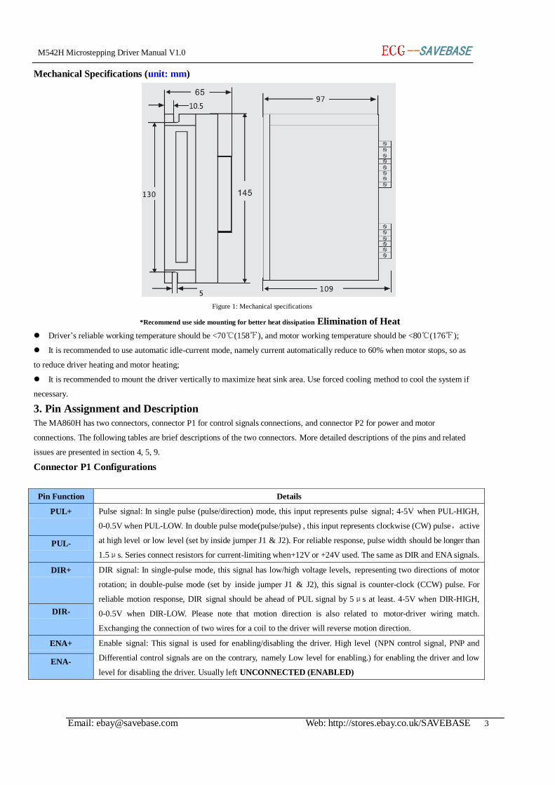
Mechanical Specifications (unit: mm)
Figure 1: Mechanical specifications
*Recommend use side mounting for better heat dissipation Elimination of Heat
Driver’s reliable working temperature should be <70℃(158℉), and motor working temperature should be <80℃(176℉);
It is recommended to use automatic idle-current mode, namely current automatically reduce to 60% when motor stops, so as
to reduce driver heating and motor heating;
It is recommended to mount the driver vertically to maximize heat sink area. Use forced cooling method to cool the system if
necessary.
3. Pin Assignment and Description
The MA860H has two connectors, connector P1 for control signals connections, and connector P2 for power and motor
connections. The following tables are brief descriptions of the two connectors. More detailed descriptions of the pins and related
issues are presented in section 4, 5, 9.
Connector P1 Configurations
Pin Function Details
PUL+ Pulse signal: In single pulse (pulse/direction) mode, this input represents pulse signal; 4-5V when PUL-HIGH,
0-0.5V when PUL-LOW. In double pulse mode(pulse/pulse) , this input represents clockwise (CW) pulse,active
at high level or low level (set by inside jumper J1 & J2). For reliable response, pulse width should be longer than
1.5μs. Series connect resistors for current-limiting when+12V or +24V used. The same as DIR and ENA signals.
PUL-
DIR+ DIR signal: In single-pulse mode, this signal has low/high voltage levels, representing two directions of motor
rotation; in double-pulse mode (set by inside jumper J1 & J2), this signal is counter-clock (CCW) pulse. For
reliable motion response, DIR signal should be ahead of PUL signal by 5μs at least. 4-5V when DIR-HIGH,
0-0.5V when DIR-LOW. Please note that motion direction is also related to motor-driver wiring match.
Exchanging the connection of two wires for a coil to the driver will reverse motion direction.
DIR-
ENA+ Enable signal: This signal is used for enabling/disabling the driver. High level (NPN control signal, PNP and
Differential control signals are on the contrary, namely Low level for enabling.) for enabling the driver and low
level for disabling the driver. Usually left UNCONNECTED (ENABLED)
ENA-
M542H Microstepping Driver Manual V1.0 ----SSAAVVEEBBAASSEE
Email: [email protected] Web: http://stores.ebay.co.uk/SAVEBASE 4
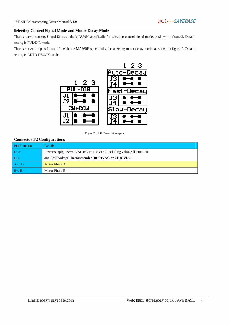
Selecting Control Signal Mode and Motor Decay Mode
There are two jumpers J1 and J2 inside the MA860H specifically for selecting control signal mode, as shown in figure 2. Default
setting is PUL/DIR mode.
There are two jumpers J1 and J2 inside the MA860H specifically for selecting motor decay mode, as shown in figure 2. Default
setting is AUTO-DECAY mode
Figure 2: J1 J2 J3 and J4 jumpers
Connector P2 Configurations
Pin Function Details
DC+ Power supply, 18~80 VAC or 24~110 VDC, Including voltage fluctuation
and EMF voltage. Recommended 18~60VAC or 24~85VDC DC-
A+, A- Motor Phase A
B+, B- Motor Phase B
M542H Microstepping Driver Manual V1.0 ----SSAAVVEEBBAASSEE
Email: [email protected] Web: http://stores.ebay.co.uk/SAVEBASE 5
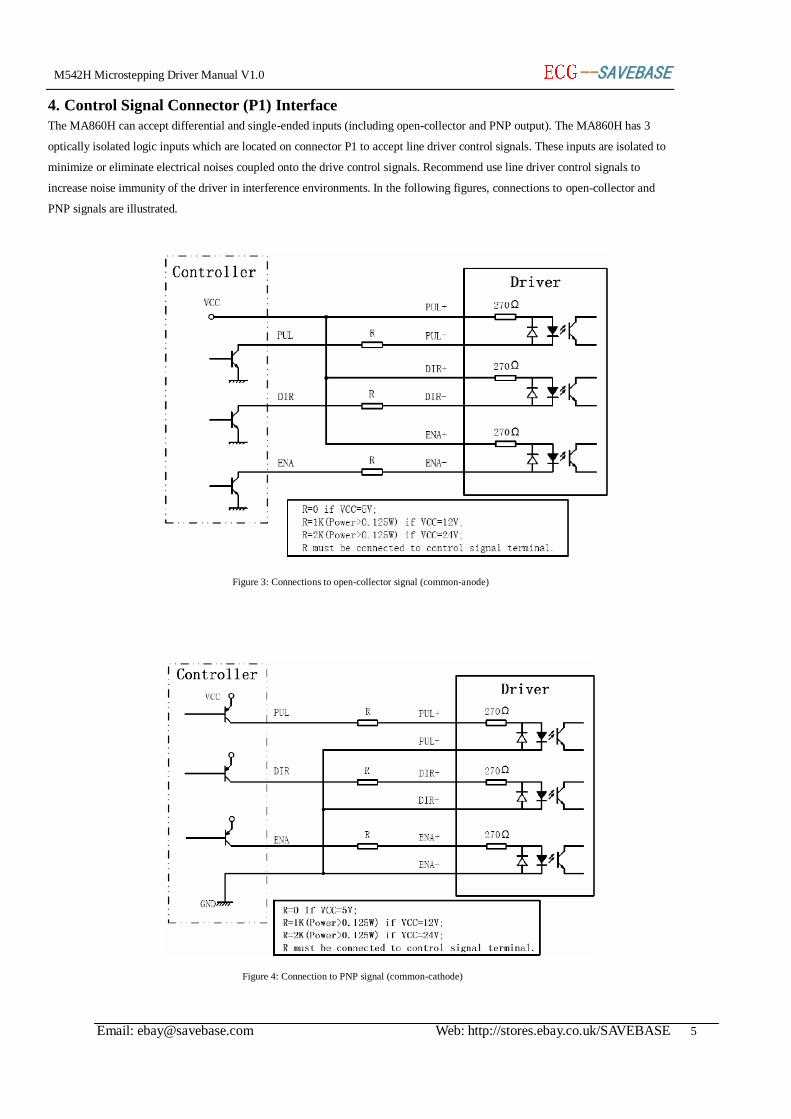
4. Control Signal Connector (P1) Interface
The MA860H can accept differential and single-ended inputs (including open-collector and PNP output). The MA860H has 3
optically isolated logic inputs which are located on connector P1 to accept line driver control signals. These inputs are isolated to
minimize or eliminate electrical noises coupled onto the drive control signals. Recommend use line driver control signals to
increase noise immunity of the driver in interference environments. In the following figures, connections to open-collector and
PNP signals are illustrated.
Figure 3: Connections to open-collector signal (common-anode)
Figure 4: Connection to PNP signal (common-cathode)
M542H Microstepping Driver Manual V1.0 ----SSAAVVEEBBAASSEE
Email: [email protected] Web: http://stores.ebay.co.uk/SAVEBASE 6
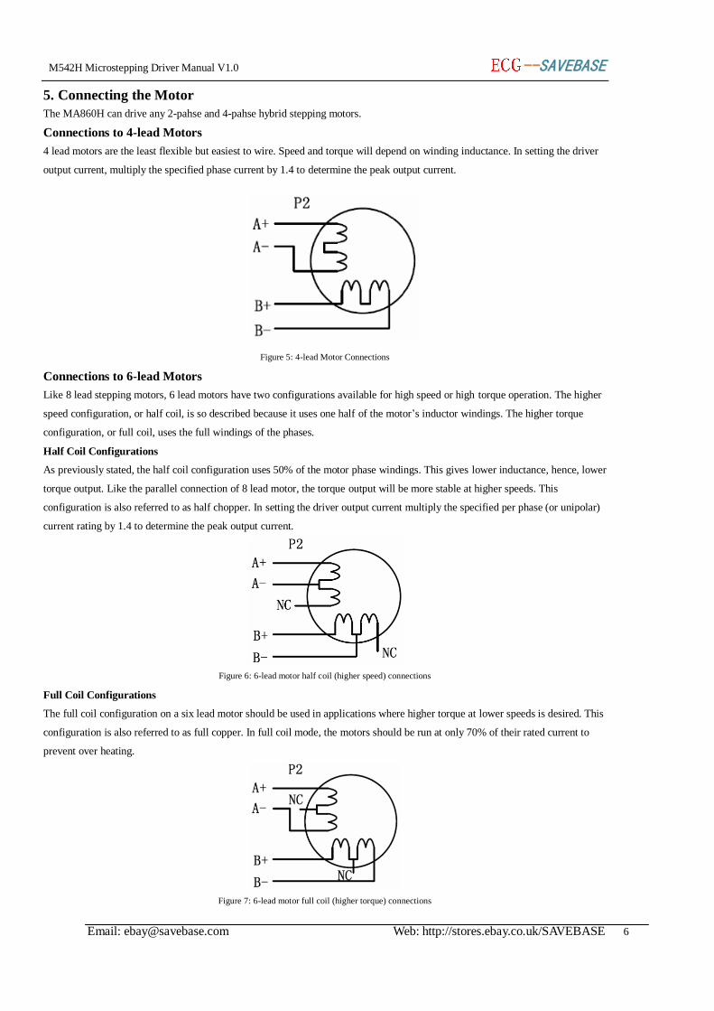
5. Connecting the Motor
The MA860H can drive any 2-pahse and 4-pahse hybrid stepping motors.
Connections to 4-lead Motors
4 lead motors are the least flexible but easiest to wire. Speed and torque will depend on winding inductance. In setting the driver
output current, multiply the specified phase current by 1.4 to determine the peak output current.
Figure 5: 4-lead Motor Connections
Connections to 6-lead Motors
Like 8 lead stepping motors, 6 lead motors have two configurations available for high speed or high torque operation. The higher
speed configuration, or half coil, is so described because it uses one half of the motor’s inductor windings. The higher torque
configuration, or full coil, uses the full windings of the phases.
Half Coil Configurations
As previously stated, the half coil configuration uses 50% of the motor phase windings. This gives lower inductance, hence, lower
torque output. Like the parallel connection of 8 lead motor, the torque output will be more stable at higher speeds. This
configuration is also referred to as half chopper. In setting the driver output current multiply the specified per phase (or unipolar)
current rating by 1.4 to determine the peak output current.
Figure 6: 6-lead motor half coil (higher speed) connections
Full Coil Configurations
The full coil configuration on a six lead motor should be used in applications where higher torque at lower speeds is desired. This
configuration is also referred to as full copper. In full coil mode, the motors should be run at only 70% of their rated current to
prevent over heating.
Figure 7: 6-lead motor full coil (higher torque) connections
M542H Microstepping Driver Manual V1.0 ----SSAAVVEEBBAASSEE
Email: [email protected] Web: http://stores.ebay.co.uk/SAVEBASE 7
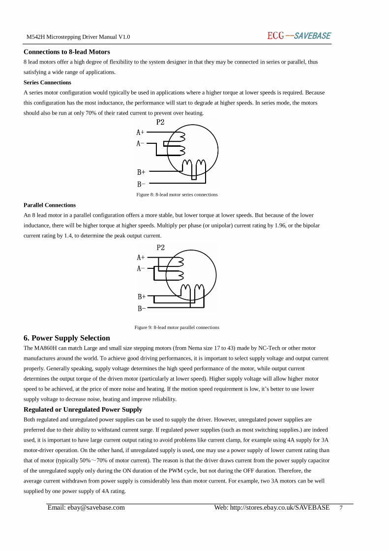
Connections to 8-lead Motors
8 lead motors offer a high degree of flexibility to the system designer in that they may be connected in series or parallel, thus
satisfying a wide range of applications.
Series Connections
A series motor configuration would typically be used in applications where a higher torque at lower speeds is required. Because
this configuration has the most inductance, the performance will start to degrade at higher speeds. In series mode, the motors
should also be run at only 70% of their rated current to prevent over heating.
Figure 8: 8-lead motor series connections
Parallel Connections
An 8 lead motor in a parallel configuration offers a more stable, but lower torque at lower speeds. But because of the lower
inductance, there will be higher torque at higher speeds. Multiply per phase (or unipolar) current rating by 1.96, or the bipolar
current rating by 1.4, to determine the peak output current.
Figure 9: 8-lead motor parallel connections
6. Power Supply Selection
The MA860H can match Large and small size stepping motors (from Nema size 17 to 43) made by NC-Tech or other motor
manufactures around the world. To achieve good driving performances, it is important to select supply voltage and output current
properly. Generally speaking, supply voltage determines the high speed performance of the motor, while output current
determines the output torque of the driven motor (particularly at lower speed). Higher supply voltage will allow higher motor
speed to be achieved, at the price of more noise and heating. If the motion speed requirement is low, it’s better to use lower
supply voltage to decrease noise, heating and improve reliability.
Regulated or Unregulated Power Supply
Both regulated and unregulated power supplies can be used to supply the driver. However, unregulated power supplies are
preferred due to their ability to withstand current surge. If regulated power supplies (such as most switching supplies.) are indeed
used, it is important to have large current output rating to avoid problems like current clamp, for example using 4A supply for 3A
motor-driver operation. On the other hand, if unregulated supply is used, one may use a power supply of lower current rating than
that of motor (typically 50%~70% of motor current). The reason is that the driver draws current from the power supply capacitor
of the unregulated supply only during the ON duration of the PWM cycle, but not during the OFF duration. Therefore, the
average current withdrawn from power supply is considerably less than motor current. For example, two 3A motors can be well
supplied by one power supply of 4A rating.
M542H Microstepping Driver Manual V1.0 ----SSAAVVEEBBAASSEE
Email: [email protected] Web: http://stores.ebay.co.uk/SAVEBASE 8
Multiple Drivers
It is recommended to have multiple drivers to share one power supply to reduce cost, if the supply has enough capacity. To avoid
cross interference, DO NOT daisy-chain the power supply input pins of the drivers. (Instead, please connect them to power
supply separately.)
Selecting Supply Voltage
The power MOSFETS inside the MA860H can actually operate within 18 ~ 80VAC or +24 ~ +110VDC, including power input
fluctuation and back EMF voltage generated by motor coils during motor shaft deceleration. Higher supply voltage can increase
motor torque at higher speeds, thus helpful for avoiding losing steps. However, higher voltage may cause bigger motor vibration
at lower speed, and it may also cause over-voltage protection or even driver damage. Therefore, it is suggested to choose only
sufficiently high supply voltage for intended applications, and it is suggested to use power supplies with theoretical output voltage
of 18 ~ 60VAC or +24 ~ +85VDC, leaving room for power fluctuation and back-EMF.
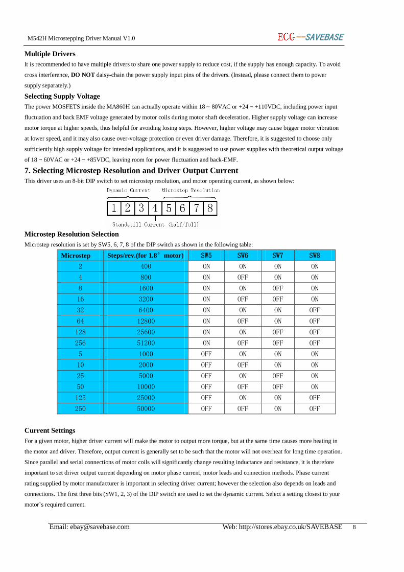
7. Selecting Microstep Resolution and Driver Output Current
This driver uses an 8-bit DIP switch to set microstep resolution, and motor operating current, as shown below:
Microstep Resolution Selection
Microstep resolution is set by SW5, 6, 7, 8 of the DIP switch as shown in the following table:
Microstep Steps/rev.(for 1.8°motor) SW5 SW6 SW7 SW8
2 400 ON ON ON ON
4 800 ON OFF ON ON
8 1600 ON ON OFF ON
16 3200 ON OFF OFF ON
32 6400 ON ON ON OFF
64 12800 ON OFF ON OFF
128 25600 ON ON OFF OFF
256 51200 ON OFF OFF OFF
5 1000 OFF ON ON ON
10 2000 OFF OFF ON ON
25 5000 OFF ON OFF ON
50 10000 OFF OFF OFF ON
125 25000 OFF ON ON OFF
250 50000 OFF OFF ON OFF
Current Settings
For a given motor, higher driver current will make the motor to output more torque, but at the same time causes more heating in
the motor and driver. Therefore, output current is generally set to be such that the motor will not overheat for long time operation.
Since parallel and serial connections of motor coils will significantly change resulting inductance and resistance, it is therefore
important to set driver output current depending on motor phase current, motor leads and connection methods. Phase current
rating supplied by motor manufacturer is important in selecting driver current; however the selection also depends on leads and
connections. The first three bits (SW1, 2, 3) of the DIP switch are used to set the dynamic current. Select a setting closest to your
motor’s required current.
M542H Microstepping Driver Manual V1.0 ----SSAAVVEEBBAASSEE
Email: [email protected] Web: http://stores.ebay.co.uk/SAVEBASE 9
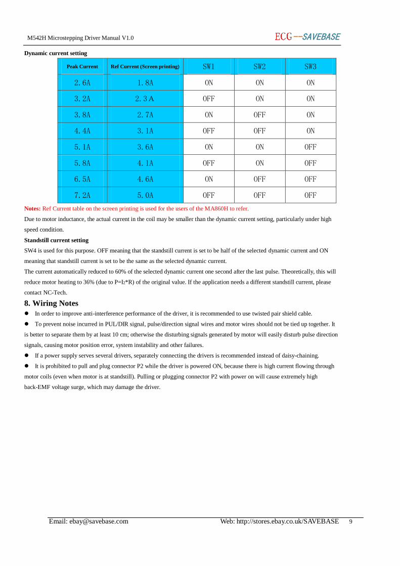
Dynamic current setting
Peak Current Ref Current (Screen printing) SW1 SW2 SW3
2.6A 1.8A ON ON ON
3.2A 2.3A OFF ON ON
3.8A 2.7A ON OFF ON
4.4A 3.1A OFF OFF ON
5.1A 3.6A ON ON OFF
5.8A 4.1A OFF ON OFF
6.5A 4.6A ON OFF OFF
7.2A 5.0A OFF OFF OFF
Notes: Ref Current table on the screen printing is used for the users of the MA860H to refer.
Due to motor inductance, the actual current in the coil may be smaller than the dynamic current setting, particularly under high
speed condition.
Standstill current setting
SW4 is used for this purpose. OFF meaning that the standstill current is set to be half of the selected dynamic current and ON
meaning that standstill current is set to be the same as the selected dynamic current.
The current automatically reduced to 60% of the selected dynamic current one second after the last pulse. Theoretically, this will
reduce motor heating to 36% (due to P=I2*R) of the original value. If the application needs a different standstill current, please
contact NC-Tech.
8. Wiring Notes
In order to improve anti-interference performance of the driver, it is recommended to use twisted pair shield cable.
To prevent noise incurred in PUL/DIR signal, pulse/direction signal wires and motor wires should not be tied up together. It
is better to separate them by at least 10 cm; otherwise the disturbing signals generated by motor will easily disturb pulse direction
signals, causing motor position error, system instability and other failures.
If a power supply serves several drivers, separately connecting the drivers is recommended instead of daisy-chaining.
It is prohibited to pull and plug connector P2 while the driver is powered ON, because there is high current flowing through
motor coils (even when motor is at standstill). Pulling or plugging connector P2 with power on will cause extremely high
back-EMF voltage surge, which may damage the driver.
M542H Microstepping Driver Manual V1.0 ----SSAAVVEEBBAASSEE
Email: [email protected] Web: http://stores.ebay.co.uk/SAVEBASE 10
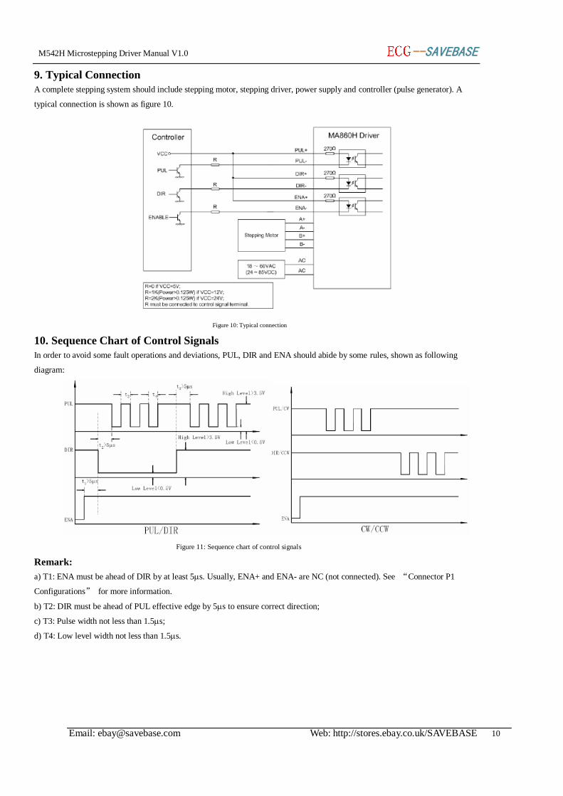
9. Typical Connection
A complete stepping system should include stepping motor, stepping driver, power supply and controller (pulse generator). A
typical connection is shown as figure 10.
Figure 10: Typical connection
10. Sequence Chart of Control Signals
In order to avoid some fault operations and deviations, PUL, DIR and ENA should abide by some rules, shown as following
diagram:
Figure 11: Sequence chart of control signals
Remark:
a) T1: ENA must be ahead of DIR by at least 5s. Usually, ENA+ and ENA- are NC (not connected). See “Connector P1
Configurations” for more information.
b) T2: DIR must be ahead of PUL effective edge by 5s to ensure correct direction;
c) T3: Pulse width not less than 1.5s;
d) T4: Low level width not less than 1.5s.
M542H Microstepping Driver Manual V1.0 ----SSAAVVEEBBAASSEE
Email: [email protected] Web: http://stores.ebay.co.uk/SAVEBASE 11
11. Protection Functions
To improve reliability, the driver incorporates some built-in protections features.
Short-voltage and Over-voltage protection
When power supply voltage exceeds 123VAC or +173VDC, over-voltage protection will be activated and Alarm indicator LED
will turn on.
Over-current Protection
Protection will be activated when continuous current exceeds the limit.
Short Circuit Protection
Protection will be activated in case of short circuit between motor coils or between motor coil and ground.
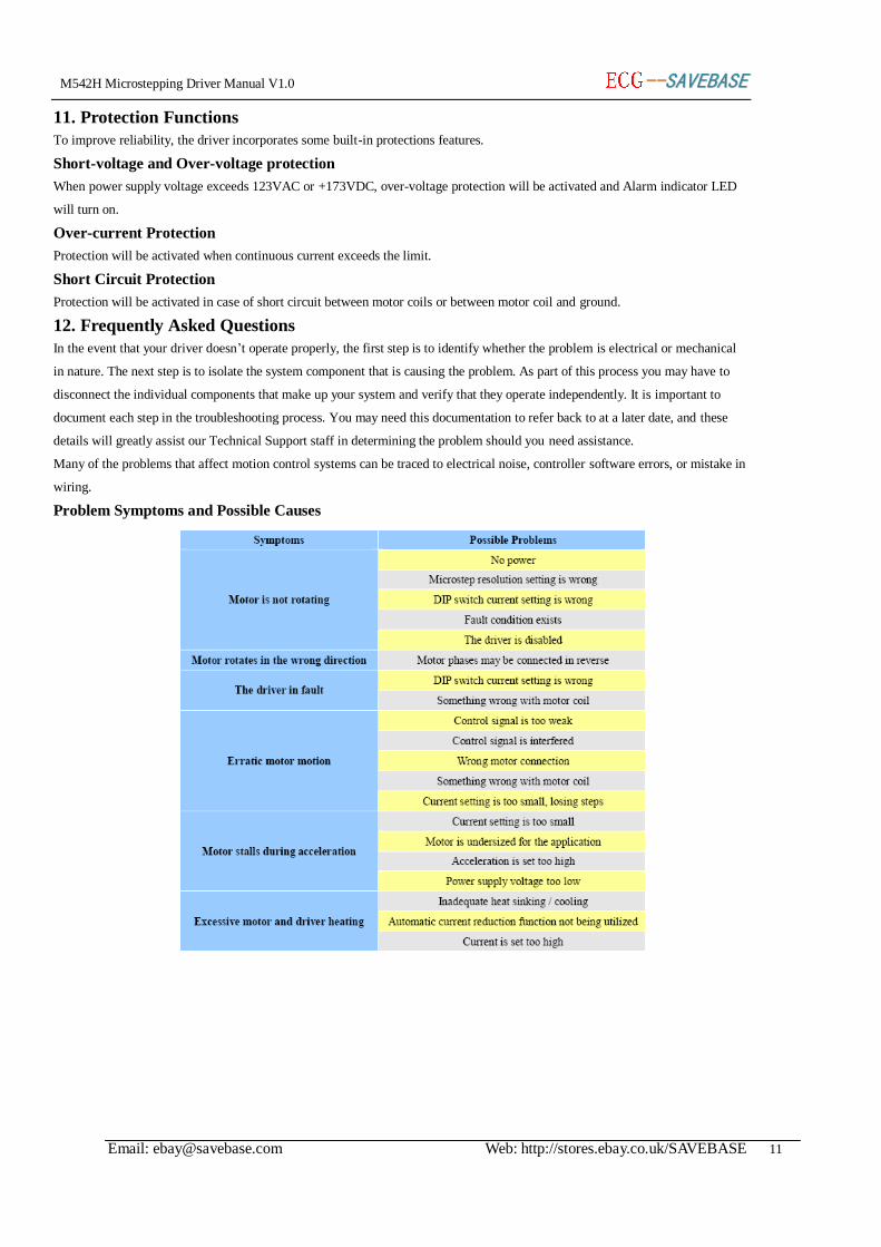
12. Frequently Asked Questions
In the event that your driver doesn’t operate properly, the first step is to identify whether the problem is electrical or mechanical
in nature. The next step is to isolate the system component that is causing the problem. As part of this process you may have to
disconnect the individual components that make up your system and verify that they operate independently. It is important to
document each step in the troubleshooting process. You may need this documentation to refer back to at a later date, and these
details will greatly assist our Technical Support staff in determining the problem should you need assistance.
Many of the problems that affect motion control systems can be traced to electrical noise, controller software errors, or mistake in
wiring.
Problem Symptoms and Possible Causes