Embed Size (px)
Citation preview
For Machining Heat-Resistant Alloy
PR005S/PR015S
Providing Stable and Consistent Performance while Machining of Heat-Resistant Alloys
PR005SPR015S
For Machining Heat-Resistant Alloy
Improved Thermal Properties Help to Reduce Sudden Fracture and Decrease Edge Wear
Improved Wear Resistance with MEGACOAT HARD Coating
Low-cutting Force and Stable Machining with Newly Designed Chipbreakers (SQ/SX/SG)
For Roughing Applications
SG ChipbreakerNEW
1
Oxidation Resistance
40
35
30
25
20
15
10400 600 800 1,000 1,200 1,400
Low High
MEGACOATTiCN
TiN
TiAIN
MEGACOAT HARD
Har
dnes
s (GPa)
Oxidation Onset Temperature (°C)
PR005S Conventional Substrate "A"
(Pattern Diagram)
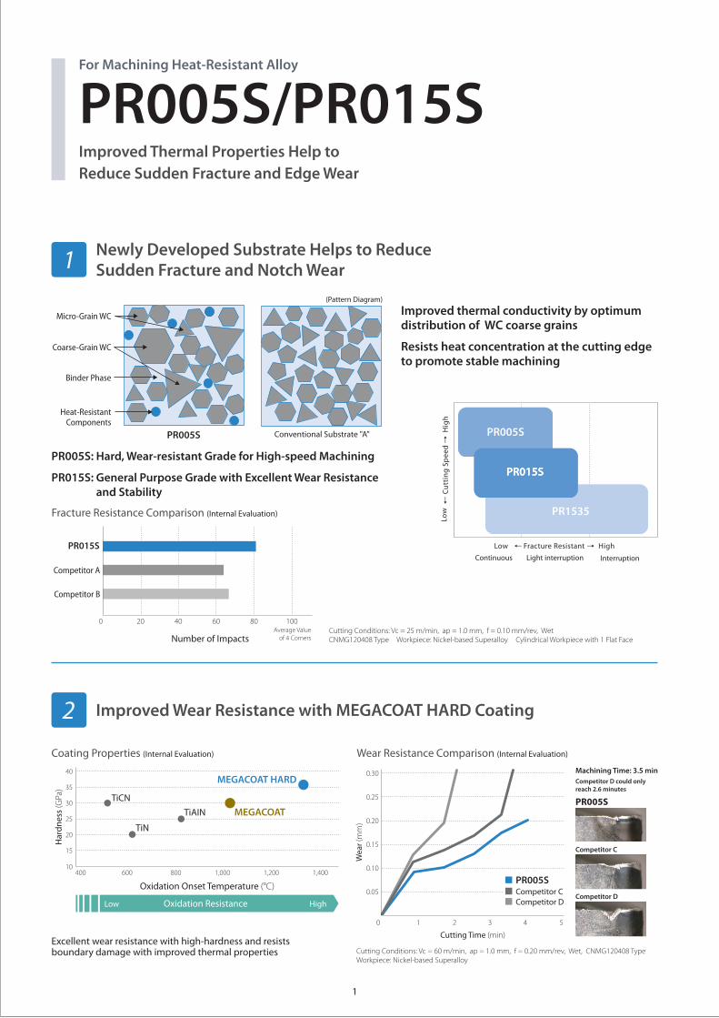
PR005S/PR015SImproved Thermal Properties Help to Reduce Sudden Fracture and Edge Wear
For Machining Heat-Resistant Alloy
Cutting Conditions: Vc = 25 m/min, ap = 1.0 mm, f = 0.10 mm/rev, WetCNMG120408 Type Workpiece: Nickel-based Superalloy Cylindrical Workpiece with 1 Flat Face
Cutting Conditions: Vc = 60 m/min, ap = 1.0 mm, f = 0.20 mm/rev, Wet, CNMG120408 TypeWorkpiece: Nickel-based Superalloy
Newly Developed Substrate Helps to Reduce Sudden Fracture and Notch Wear1
Improved Wear Resistance with MEGACOAT HARD Coating
Improved thermal conductivity by optimum distribution of WC coarse grains
Resists heat concentration at the cutting edge to promote stable machining
PR005S: Hard, Wear-resistant Grade for High-speed Machining
PR015S: General Purpose Grade with Excellent Wear Resistance and Stability
2
10080604020
PR015S
Competitor B
Competitor A
0Average Value
of 4 CornersNumber of Impacts
Fracture Resistance Comparison (Internal Evaluation)
Machining Time: 3.5 min
PR005S
Competitor C
Competitor D
Coating Properties (Internal Evaluation)
0 1 42 3 5
Cutting Time (min)
0.30
0.25
0.20
0.15
0.10
0.05
Wea
r (mm)
PR005SCompetitor CCompetitor D
Wear Resistance Comparison (Internal Evaluation)
Excellent wear resistance with high-hardness and resists boundary damage with improved thermal properties
Competitor D could only reach 2.6 minutes
Interruption
Fracture Resistant
Continuous Light interruption
PR1535
PR005S
PR015SPR015S
Low High
Cu
ttin
g S
pee
dLo
wH
igh
Micro-Grain WC
Coarse-Grain WC
Binder Phase
Heat-Resistant Components
2
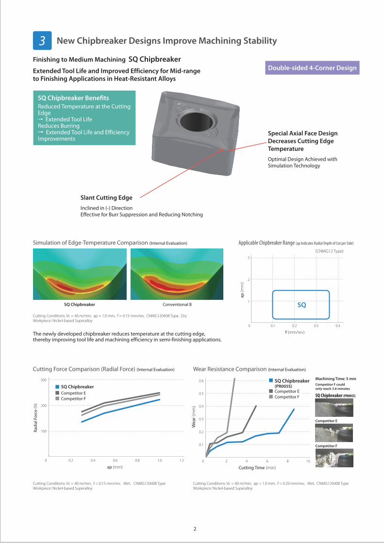
Simulation of Edge-Temperature Comparison (Internal Evaluation) Applicable Chipbreaker Range (ap Indicates Radial Depth of Cut per Side)
Cutting Conditions: Vc = 40 m/min, ap = 1.0 mm, f = 0.15 mm/rev, CNMG120408 Type, DryWorkpiece: Nickel-based Superalloy
New Chipbreaker Designs Improve Machining Stability3
The newly developed chipbreaker reduces temperature at the cutting edge, thereby improving tool life and machining efficiency in semi-finishing applications.
SQ Chipbreaker Conventional B
Finishing to Medium Machining SQ Chipbreaker
Extended Tool Life and Improved Efficiency for Mid-range to Finishing Applications in Heat-Resistant Alloys
SQ Chipbreaker BenefitsReduced Temperature at the Cutting Edge
Extended Tool Life Reduces Burring
Extended Tool Life and Efficiency Improvements
Slant Cutting Edge
Inclined in (-) DirectionEffective for Burr Suppression and Reducing Notching
Special Axial Face Design Decreases Cutting Edge Temperature
Optimal Design Achieved with Simulation Technology
Cutting Conditions: Vc = 40 m/min, ap = 1.0 mm, f = 0.20 mm/rev, Wet, CNMG120408 TypeWorkpiece: Nickel-based Superalloy
Cutting Conditions: Vc = 40 m/min, f = 0.15 mm/rev, Wet, CNMG120408 TypeWorkpiece: Nickel-based Superalloy
Machining Time: 5 min
0 2 84 6 10
Cutting Time (min)
0.6
0.5
0.4
0.3
0.2
0.1
Wea
r (m
m)
SQ Chipbreaker(PR005S)
Competitor FCompetitor E
0 0.2 0.80.4 0.6 1.21.0
ap (mm)
300
200
100Radi
al F
orce
(N)
SQ ChipbreakerCompetitor ECompetitor F
Wear Resistance Comparison (Internal Evaluation)Cutting Force Comparison (Radial Force) (Internal Evaluation)
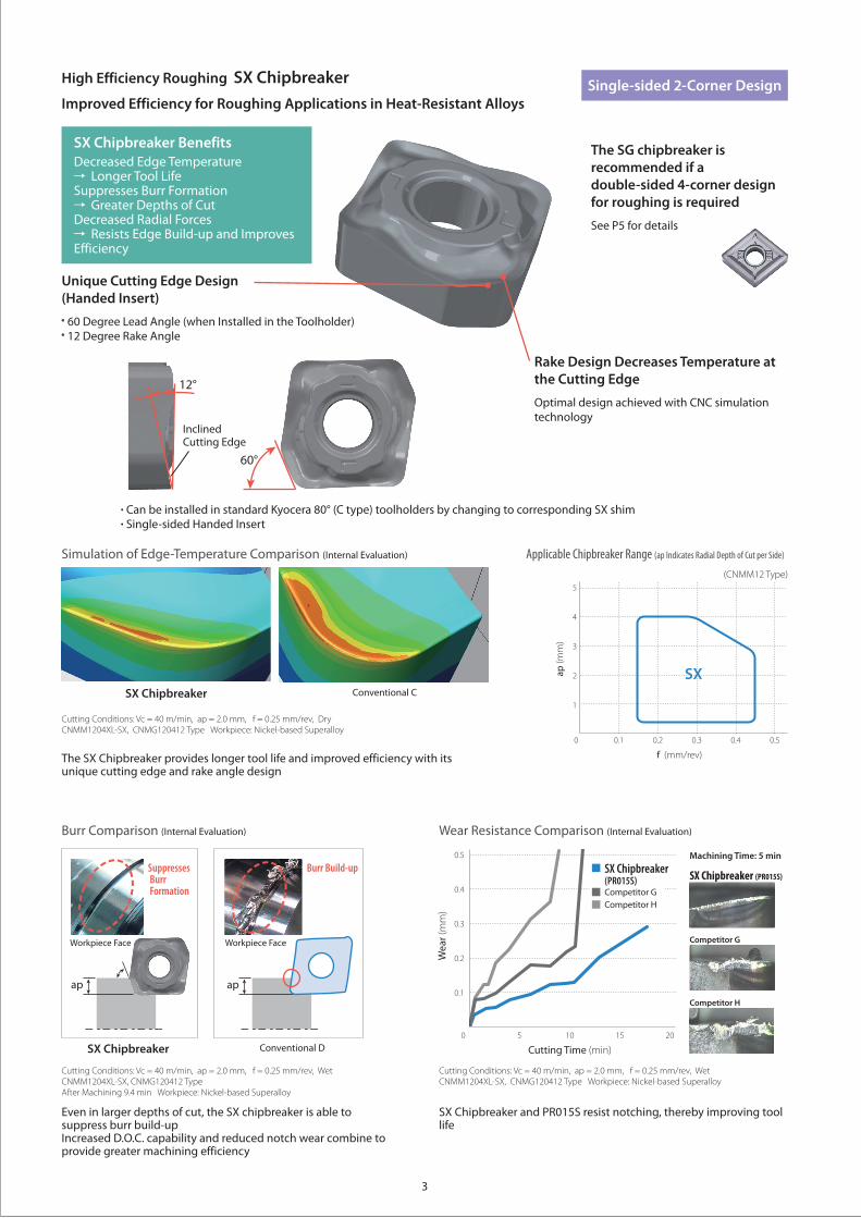
Competitor F could only reach 3.6 minutes
SQ Chipbreaker (PR005S)
Competitor F
Competitor E
0 0.1 0.40.2 0.3
f (mm/rev)
3
2
1
ap (m
m)
SQ
(CNMG12 Type)
Double-sided 4-Corner Design
3
Applicable Chipbreaker Range (ap Indicates Radial Depth of Cut per Side)Simulation of Edge-Temperature Comparison (Internal Evaluation)
Burr Comparison (Internal Evaluation)
Cutting Conditions: Vc = 40 m/min, ap = 2.0 mm, f = 0.25 mm/rev, DryCNMM1204XL-SX, CNMG120412 Type Workpiece: Nickel-based Superalloy
Cutting Conditions: Vc = 40 m/min, ap = 2.0 mm, f = 0.25 mm/rev, WetCNMM1204XL-SX, CNMG120412 TypeAfter Machining 9.4 min Workpiece: Nickel-based Superalloy
The SX Chipbreaker provides longer tool life and improved efficiency with its unique cutting edge and rake angle design
Even in larger depths of cut, the SX chipbreaker is able to suppress burr build-upIncreased D.O.C. capability and reduced notch wear combine to provide greater machining efficiency
SX Chipbreaker
SX Chipbreaker
Conventional C
Conventional D
High Efficiency Roughing SX Chipbreaker
Improved Efficiency for Roughing Applications in Heat-Resistant Alloys
SX Chipbreaker BenefitsDecreased Edge Temperature
Longer Tool LifeSuppresses Burr Formation
Greater Depths of CutDecreased Radial Forces
Resists Edge Build-up and Improves Efficiency
Can be installed in standard Kyocera 80° (C type) toolholders by changing to corresponding SX shim Single-sided Handed Insert
Rake Design Decreases Temperature at the Cutting Edge
Optimal design achieved with CNC simulation technology
Inclined Cutting Edge
12°
60°
apap
Workpiece Face Workpiece Face
Burr Build-upSuppresses Burr Formation
Cutting Conditions: Vc = 40 m/min, ap = 2.0 mm, f = 0.25 mm/rev, WetCNMM1204XL-SX, CNMG120412 Type Workpiece: Nickel-based Superalloy
SX Chipbreaker and PR015S resist notching, thereby improving tool life
Machining Time: 5 min
0 5 10 15 20
Cutting Time (min)
0.5
0.4
0.3
0.2
0.1
Wea
r (m
m)
SX Chipbreaker(PR015S)Competitor GCompetitor H
Wear Resistance Comparison (Internal Evaluation)
SX Chipbreaker (PR015S)
Competitor G
Competitor H
0 0.1 0.50.40.2 0.3
f (mm/rev)
5
4
3
2
1
ap
(mm
)
SX
(CNMM12 Type)
Single-sided 2-Corner Design
Unique Cutting Edge Design (Handed Insert)
60 Degree Lead Angle (when Installed in the Toolholder) 12 Degree Rake Angle
The SG chipbreaker is recommended if a double-sided 4-corner design for roughing is required
See P5 for details
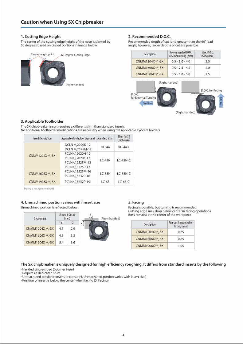
Caution when Using SX Chipbreaker
4
3. Applicable ToolholderThe SX chipbreaker insert requires a different shim than standard inserts No additional toolholder modifications are necessary when using the applicable Kyocera holders
2. Recommended D.O.C.Recommended depth of cut is no greater than the 60° lead angle; however, larger depths of cut are possible
5. FacingFacing is possible, but turning is recommended Cutting edge may drop below center in facing operations Boss remains at the center of the workpiece
4. Unmachined portion varies with insert sizeUnmachined portion is reflected below
The SX chipbreaker is uniquely designed for high efficiency roughing. It differs from standard inserts by the following Handed single-sided 2-corner insert Requires a dedicated shim Unmachined portion remains at corner (4. Unmachined portion varies with insert size) Position of insert is below the center when facing (5. Facing)
Description Recommended D.O.C.External Turning (mm)
Max. D.O.C.Facing (mm)
CNMM1204X R/L-SX 0.5 - 2.0 - 4.0 2.0
CNMM1606X R/L-SX 0.5 - 2.5 - 4.5 2.0
CNMM1906X R/L-SX 0.5 - 3.0 - 5.0 2.5
Description Run-out Amount when Facing (mm)
CNMM1204X R/L-SX 0.75
CNMM1606X R/L-SX 0.85
CNMM1906X R/L-SX 1.05
Insert Description Applicable Toolholder (Kyocera) Standard Shim Shim for SX Chipbreaker
CNMM1204X R/L-SX
DCLN R/L2020K-12DCLN R/L2525M-12
DC-44 DC-44-C
PCLN R/L2020H-12PCLN R/L2020K-12PCLN R/L2525M-12PCLN R/L3225P-12
LC-42N LC-42N-C
CNMM1606X R/L-SXPCLN R/L2525M-16PCLN R/L3232P-16
LC-53N LC-53N-C
CNMM1906X R/L-SX PCLN R/L3232P-19 LC-63 LC-63-C
Boring is not recommended
(Right-handed)
60 Degree Cutting EdgeCenter height point
DescriptionAmount Uncut
(mm)X Z
CNMM1204X R/L-SX 4.1 2.9
CNMM1606X R/L-SX 4.8 3.3
CNMM1906X R/L-SX 5.4 3.6
D.O.C. for External Turning
D.O.C. for Facing
(Right-handed)
(Right-handed)
(Right-handed)
X
Z
Feed Rate
Feed
Rat
e
D.O.C. for External Turning
D.O.C. for Facing
(Right-handed)
(Right-handed)
(Right-handed)
X
Z
Feed Rate
Feed
Rat
e
1. Cutting Edge HeightThe center of the cutting edge height of the nose is slanted by 60 degrees based on circled portions in image below
5
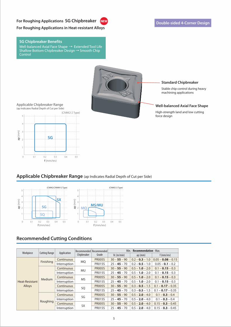
Applicable Chipbreaker Range (ap Indicates Radial Depth of Cut per Side)
Recommended Cutting Conditions
0 0.1 0.40.2 0.3 0.5
f (mm/rev)
5
4
3
2
1
ap
(mm
)
0 0.1 0.40.2 0.3 0.5
f (mm/rev)
5
4
3
2
1
ap
(mm
)
MQ
SX
SG
SQ
MS/MU
(CNMG/CNMM12 Type) (CNMG12 Type)
Workpiece Cutting Range Application Recommended Chipbreaker
Recommended Grade
Min. - Recommendation - Max.Vc (m/min) ap (mm) f (mm/rev)
Heat-Resistant Alloys
FinishingContinuous
MQPR005S 30 – 55 – 90 0.2 – 0.3 – 1.0 0.05 – 0.08 – 0.15
Interruption PR015S 25 – 45 – 70 0.2 – 0.5 – 1.0 0.05 – 0.1 – 0.2
Medium
ContinuousMU
PR005S 30 – 55 – 90 0.5 – 1.0 – 2.0 0.1 – 0.15 – 0.3Interruption PR015S 25 – 45 – 70 0.5 – 1.0 – 2.0 0.1 – 0.15 – 0.3Continuous
MSPR005S 30 – 55 – 90 0.5 – 1.0 – 2.0 0.1 – 0.15 – 0.3
Interruption PR015S 25 – 45 – 70 0.5 – 1.0 – 2.0 0.1 – 0.15 – 0.3Continuous
SQPR005S 30 – 55 – 90 0.3 – 0.5 – 1.5 0.1 – 0.17 – 0.35
Interruption PR015S 25 – 45 – 70 0.3 – 0.5 – 1.5 0.1 – 0.17 – 0.35
Roughing
ContinuousSG
PR005S 30 – 55 – 90 0.5 – 2.0 – 4.0 0.1 – 0.3 – 0.4Interruption PR015S 25 – 45 – 70 0.5 – 2.0 – 4.0 0.1 – 0.3 – 0.4Continuous
SXPR005S 30 – 55 – 90 0.5 – 2.0 – 4.0 0.15 – 0.3 – 0.45
Interruption PR015S 25 – 45 – 70 0.5 – 2.0 – 4.0 0.15 – 0.3 – 0.45
For Roughing Applications SG Chipbreaker
For Roughing Applications in Heat-resistant Alloys
SG Chipbreaker BenefitsWell-balanced Axial Face Shape Extended Tool LifeShallow Bottom Chipbreaker Design Smooth Chip Control
Well-balanced Axial Face Shape
High-strength land and low cutting force design
Standard Chipbreaker
Stable chip control during heavy machining applications
Double-sided 4-Corner Design
0 0.1 0.50.40.2 0.3
f (mm/rev)
5
4
3
2
1
ap (m
m)
SG
(CNMG12 Type)
Applicable Chipbreaker Range (ap Indicates Radial Depth of Cut per Side)
NEW
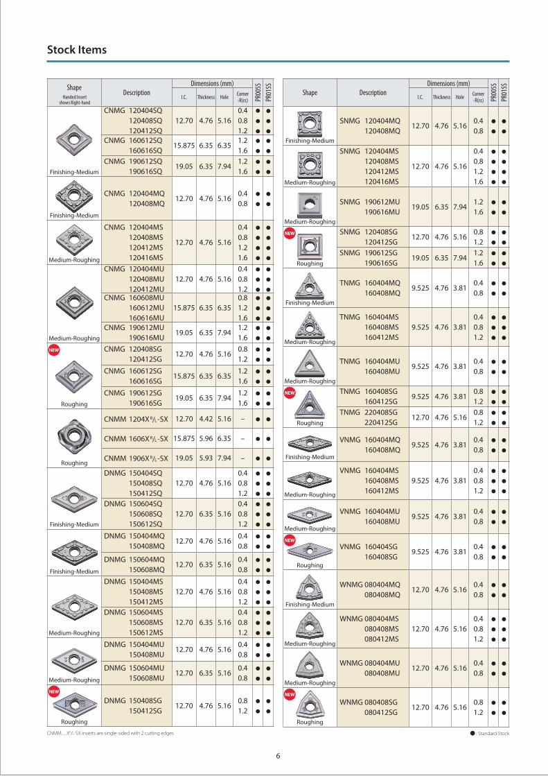
Stock Items
6
ShapeDescription
Dimensions (mm)
PR00
5SPR
015S
I.C. Thickness Hole Corner-R(rε)
Finishing-Medium
CNMG 120404SQ 120408SQ 120412SQ
12.70 4.76 5.160.40.81.2
CNMG 160612SQ 160616SQ
15.875 6.35 6.351.21.6
CNMG 190612SQ 190616SQ
19.05 6.35 7.941.21.6
Finishing-Medium
CNMG 120404MQ 120408MQ
12.70 4.76 5.160.40.8
Medium-Roughing
CNMG 120404MS 120408MS 120412MS 120416MS
12.70 4.76 5.16
0.40.81.21.6
Medium-Roughing
CNMG 120404MU 120408MU 120412MU
12.70 4.76 5.160.40.81.2
CNMG 160608MU 160612MU 160616MU
15.875 6.35 6.350.81.21.6
CNMG 190612MU 190616MU
19.05 6.35 7.941.21.6
Roughing
CNMG 120408SG 120412SG
12.70 4.76 5.160.81.2
CNMG 160612SG 160616SG
15.875 6.35 6.351.21.6
CNMG 190612SG 190616SG
19.05 6.35 7.941.21.6
Roughing
CNMM 1204XR/L-SX 12.70 4.42 5.16 –
CNMM 1606XR/L-SX 15.875 5.96 6.35 –
CNMM 1906XR/L-SX 19.05 5.93 7.94 –
Finishing-Medium
DNMG 150404SQ 150408SQ 150412SQ
12.70 4.76 5.160.40.81.2
DNMG 150604SQ 150608SQ 150612SQ
12.70 6.35 5.160.40.81.2
Finishing-Medium
DNMG 150404MQ 150408MQ
12.70 4.76 5.160.40.8
DNMG 150604MQ 150608MQ
12.70 6.35 5.160.40.8
Medium-Roughing
DNMG 150404MS 150408MS 150412MS
12.70 4.76 5.160.40.81.2
DNMG 150604MS 150608MS 150612MS
12.70 6.35 5.160.40.81.2
Medium-Roughing
DNMG 150404MU 150408MU
12.70 4.76 5.160.40.8
DNMG 150604MU 150608MU
12.70 6.35 5.160.40.8
Roughing
DNMG 150408SG 150412SG
12.70 4.76 5.160.81.2
Shape DescriptionDimensions (mm)
PR00
5SPR
015S
I.C. Thickness Hole Corner-R(rε)
Finishing-Medium
SNMG 120404MQ 120408MQ
12.70 4.76 5.160.40.8
Medium-Roughing
SNMG 120404MS 120408MS 120412MS 120416MS
12.70 4.76 5.16
0.40.81.21.6
Medium-Roughing
SNMG 190612MU 190616MU
19.05 6.35 7.941.21.6
Roughing
SNMG 120408SG 120412SG
12.70 4.76 5.160.81.2
SNMG 190612SG 190616SG
19.05 6.35 7.941.21.6
Finishing-Medium
TNMG 160404MQ 160408MQ
9.525 4.76 3.810.40.8
Medium-Roughing
TNMG 160404MS 160408MS 160412MS
9.525 4.76 3.810.40.81.2
Medium-Roughing
TNMG 160404MU 160408MU
9.525 4.76 3.810.40.8
Roughing
TNMG 160408SG 160412SG
9.525 4.76 3.810.81.2
TNMG 220408SG 220412SG
12.70 4.76 5.160.81.2
Finishing-Medium
VNMG 160404MQ 160408MQ
9.525 4.76 3.810.40.8
Medium-Roughing
VNMG 160404MS 160408MS 160412MS
9.525 4.76 3.810.40.81.2
Medium-Roughing
VNMG 160404MU 160408MU
9.525 4.76 3.810.40.8
Roughing
VNMG 160404SG 160408SG
9.525 4.76 3.810.40.8
Finishing-Medium
WNMG 080404MQ 080408MQ
12.70 4.76 5.160.40.8
Medium-Roughing
WNMG 080404MS 080408MS 080412MS
12.70 4.76 5.160.40.81.2
Medium-Roughing
WNMG 080404MU 080408MU
12.70 4.76 5.160.40.8
Roughing
WNMG 080408SG 080412SG
12.70 4.76 5.160.81.2
: Standard StockCNMM…XR/L-SX inserts are single-sided with 2 cutting edges
Handed Insert shows Right-hand
NEW
NEW NEW
NEW
NEW
NEW

The information contained in this brochure is current as of December 2017.Duplication or reproduction of any part of this brochure without approval is prohibited.
CP409-1© 2017 KYOCERA Corporation


![Heat Resistant Molds 1[1]](https://img.pdfslide.net/doc/110x75/577ce54c1a28abf10390530b/heat-resistant-molds-11.jpg)