Embed Size (px)
Citation preview
CAMTECH/2004/E/X-mer/1.0
Maintenance of Distribution & Power Transformer December, 2004
1
Eäò´É±É EòɪÉÉDZɪÉÒxÉ ={ɪÉÉäMÉ ½äþiÉÖ
(For Official Use Only)
¦ÉÉ®úiÉ ºÉ®úEòÉ®ú ¦ÉÉ®úiÉ ºÉ®úEòÉ®ú ¦ÉÉ®úiÉ ºÉ®úEòÉ®ú ¦ÉÉ®úiÉ ºÉ®úEòÉ®ú GOVERNMENT OF INDIA
®äú±É ¨ÉÆjÉÉ±ÉªÉ ®äú±É ¨ÉÆjÉÉ±ÉªÉ ®äú±É ¨ÉÆjÉÉ±ÉªÉ ®äú±É ¨ÉÆjÉÉ±ÉªÉ MINISTRY OF RAILWAYS
Centre for Advanced Maintenance TECHnology
forj.k ,oa ikoj VªkalQkeZj dk vuqj{k.k forj.k ,oa ikoj VªkalQkeZj dk vuqj{k.k forj.k ,oa ikoj VªkalQkeZj dk vuqj{k.k forj.k ,oa ikoj VªkalQkeZj dk vuqj{k.k
MAINTENANCE
OF
DISTRIBUTION & POWER
TRANSFORMER
dseVsd@2004@bZ@VªkalQkeZj@1-0 CAMTECH/2004/E/X-mer/1.0
fnlEcj]] 2004
December, 2004
¨É½þÉ®úÉVÉ{ÉÖ®ú¨É½þÉ®úÉVÉ{ÉÖ®ú¨É½þÉ®úÉVÉ{ÉÖ®ú¨É½þÉ®úÉVÉ{ÉÖ®ú, M´ÉÉʱɪɮú M´ÉÉʱɪɮú M´ÉÉʱɪɮú M´ÉÉʱɪɮú ---- 474 020 474 020 474 020 474 020 Maharajpur, GWALIOR - 474 020
EXECELLENCE IN MAINTENANCE
CAMTECH/2004/E/X-mer/1.0
Maintenance of Distribution & Power Transformer December, 2004
2
forj.k ,oa ikoj VªkalQkeZj dk vuqj{k.k forj.k ,oa ikoj VªkalQkeZj dk vuqj{k.k forj.k ,oa ikoj VªkalQkeZj dk vuqj{k.k forj.k ,oa ikoj VªkalQkeZj dk vuqj{k.k
MAINTENANCE
OF
DISTRIBUTION & POWER
TRANSFORMER
CAMTECH/2004/E/X-mer/1.0
Maintenance of Distribution & Power Transformer December, 2004
3
FORWORD Transformer is the most important equipment provided at sub stations and needs proper maintenance to ensure reliable electrical power supply for Railway stations, offices, water pumping installations, yards, sick lines, workshops, loco sheds, residential colonies and others.
CAMTECH has prepared this handbook with the objective of improving the reliability of distribution & power transformers used in Railways. The book covers comprehensively various maintenance schedules, trouble shooting, purification of transformer oil and condition monitoring. I hope the maintenance staff will find this book extremely useful in their day-to-day work. CAMTECH, GWALIOR R.N.MISRA 23rd DECEMBER, 2004 EXECUTIVE DIRECTOR
CAMTECH/2004/E/X-mer/1.0
Maintenance of Distribution & Power Transformer December, 2004
4
PREFACE Distribution & power transformers of different ratings are provided at Railway substations for electrical power supply for yards, sick lines, workshops, loco sheds, Railway stations, offices, residential colonies & other Railway establishments. Transformer is the most important equipment installed at the sub station. Its proper upkeep and maintenance is necessary to ensure reliable electrical power supply. This handbook on maintenance of distribution & power transformer has been prepared by CAMTECH with the objective of making our maintenance personnel aware of maintenance techniques to be adopted in field. It is clarified that this handbook does not supersede any existing provisions laid down by RDSO or Railway Board and it is not a statutory document.
I am sincerely thankful to Director (PS & EMU) RDSO/LKO for his valuable comments. I am also thankful to all field personnel who helped us in preparing this handbook.
Technological upgradation and learning is a continuous process. Hence feel free to write to us for any addition/modification in this handbook. We shall highly appreciate your contribution in this direction. CAMTECH, GWALIOR RANDHAWA SUHAG 23rd DECEMBER, 2004 DIRECTOR/ ELECT
CAMTECH/2004/E/X-mer/1.0
Maintenance of Distribution & Power Transformer December, 2004
5
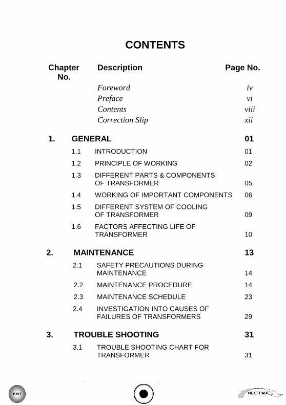
CONTENTS
Chapter Description Page No. No.
Foreword iv Preface vi Contents viii
Correction Slip xii 1. GENERAL 01
1.1 INTRODUCTION 01
1.2 PRINCIPLE OF WORKING 02
1.3 DIFFERENT PARTS & COMPONENTS OF TRANSFORMER 05
1.4 WORKING OF IMPORTANT COMPONENTS 06
1.5 DIFFERENT SYSTEM OF COOLING OF TRANSFORMER 09
1.6 FACTORS AFFECTING LIFE OF TRANSFORMER 10
2. MAINTENANCE 13
2.1 SAFETY PRECAUTIONS DURING MAINTENANCE 14
2.2 MAINTENANCE PROCEDURE 14
2.3 MAINTENANCE SCHEDULE 23
2.4 INVESTIGATION INTO CAUSES OF FAILURES OF TRANSFORMERS 29
3. TROUBLE SHOOTING 31
3.1 TROUBLE SHOOTING CHART FOR TRANSFORMER 31
CAMTECH/2004/E/X-mer/1.0
Maintenance of Distribution & Power Transformer December, 2004
6
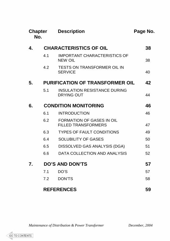
Chapter Description Page No. No. 4. CHARACTERISTICS OF OIL 38
4.1 IMPORTANT CHARACTERISTICS OF NEW OIL 38
4.2 TESTS ON TRANSFORMER OIL IN SERVICE 40
5. PURIFICATION OF TRANSFORMER OIL 42
5.1 INSULATION RESISTANCE DURING DRYING OUT 44
6. CONDITION MONITORING 46
6.1 INTRODUCTION 46
6.2 FORMATION OF GASES IN OIL FILLED TRANSFORMERS 47
6.3 TYPES OF FAULT CONDITIONS 49
6.4 SOLUBILITY OF GASES 50
6.5 DISSOLVED GAS ANALYSIS (DGA) 51
6.6 DATA COLLECTION AND ANALYSIS 52 7. DO’S AND DON’TS 57
7.1 DO’S 57
7.2 DON’TS 58 REFERENCES 59
CAMTECH/2004/E/X-mer/1.0
Maintenance of Distribution & Power Transformer December, 2004
7
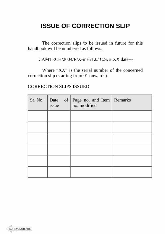
ISSUE OF CORRECTION SLIP
The correction slips to be issued in future for this handbook will be numbered as follows: CAMTECH/2004/E/X-mer/1.0/ C.S. # XX date--- Where “XX” is the serial number of the concerned correction slip (starting from 01 onwards). CORRECTION SLIPS ISSUED
Sr. No. Date of issue
Page no. and Item no. modified
Remarks
CAMTECH/2004/E/X-mer/1.0
Maintenance of Distribution & Power Transformer December, 2004
CHAPTER 1
GENERAL 1.1 INTRODUCTON
The transformer is a static device, which
transform power from one AC circuit to another AC circuit at same frequency but having different characteristics. These circuits are conductively disjointed but magnetically coupled by a common time-varying magnetic field. It can raise or lower the voltage with a corresponding decrease or increase in current.
The voltage level of generation, transmission and distribution is different. Transmission transformers are used for taking supply at far distance by stepping up the voltage to high or extra high voltage. The transmission at high voltage reduces transmission line current and hence decreases the cross-sectional area of the conductor. The distribution transformer is a step down transformer and is used to step down the voltage to a standard service voltage i.e. 33kV/11kV, 33kV/0.433kV, 11kV/0.433kV etc. These are operated for the whole day whether there is load or not. Energy is lost in iron losses for the whole day. Due to low iron losses, the distribution transformers have good efficiency.
CAMTECH/2004/E/X-mer/1.0
Maintenance of Distribution & Power Transformer December, 2004
2
1.2 PRINCIPLE OF WORKING
a. When a conductor cuts the magnetic flux or magnetic flux cut the conductor, an emf is induced in the conductor.
b. The magnitude of this emf is proportional to the
rate of change of flux. E = -dφ/dt
Where, E = emf
φ = flux Kinds of emf The emf may be induced by two ways i. Dynamically induced emf ii. Statically induced emf.
a. Mutually induced emf b. Self induced emf
An emf induced in a coil due to variation of flux
in another coil placed near to first is called mutually induced emf.
The emf induced in a coil due to change of its own flux linked with it is called self-induced emf. (In case of autotransformer)
In its simplest form, a transformer consists of two conducting coils. The primary is the winding which receives electric power, and the secondary is one which deliver the electric power. These coils are wound on a laminated core of magnetic material.
CAMTECH/2004/E/X-mer/1.0
Maintenance of Distribution & Power Transformer December, 2004
3
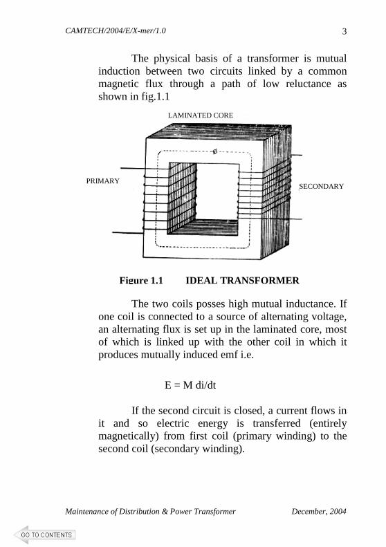
The physical basis of a transformer is mutual induction between two circuits linked by a common magnetic flux through a path of low reluctance as shown in fig.1.1
The two coils posses high mutual inductance. If
one coil is connected to a source of alternating voltage, an alternating flux is set up in the laminated core, most of which is linked up with the other coil in which it produces mutually induced emf i.e.
E = M di/dt If the second circuit is closed, a current flows in
it and so electric energy is transferred (entirely magnetically) from first coil (primary winding) to the second coil (secondary winding).
PRIMARY
LAMINATED CORE
SECONDARY
Figure 1.1 IDEAL TRANSFORMER
CAMTECH/2004/E/X-mer/1.0
Maintenance of Distribution & Power Transformer December, 2004
4
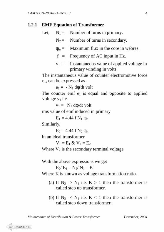
1.2.1 EMF Equation of Transformer
Let, N1 = Number of turns in primary.
N2 = Number of turns in secondary.
φm = Maximum flux in the core in webres.
f = Frequency of AC input in Hz.
v1 = Instantaneous value of applied voltage in primary winding in volts.
The instantaneous value of counter electromotive force e1, can be expressed as
e1 = - N1 dφ/dt volt The counter emf e1 is equal and opposite to applied voltage v1 i.e.
v1 = N1 dφ/dt volt rms value of emf induced in primary
E1 = 4.44 f N1 φm
Similarly,
E2 = 4.44 f N2 φm
In an ideal transformer V1 = E1 & V2 = E2
Where V2 is the secondary terminal voltage With the above expressions we get
E2/ E1 = N2/ N1 = K Where K is known as voltage transformation ratio.
(a) If N2 > N1 i.e. K > 1 then the transformer is called step up transformer.
(b) If N2 < N1 i.e. K < 1 then the transformer is called step down transformer.
CAMTECH/2004/E/X-mer/1.0
Maintenance of Distribution & Power Transformer December, 2004
5
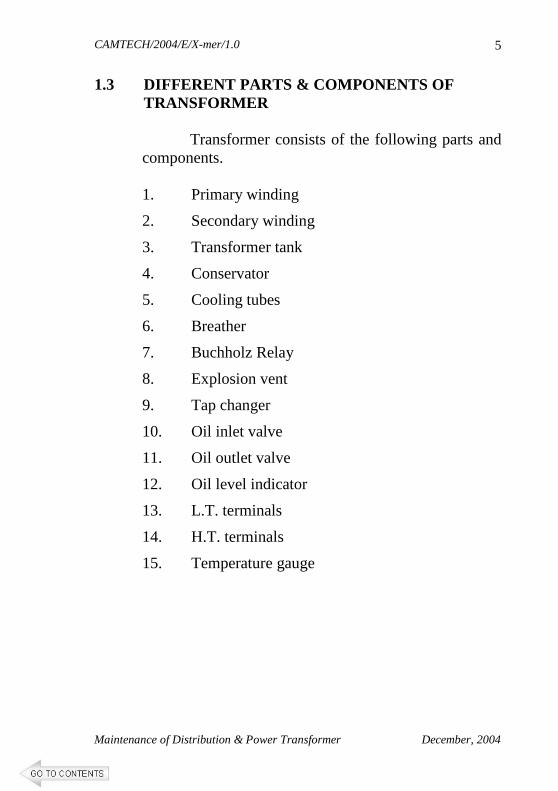
1.3 DIFFERENT PARTS & COMPONENTS OF TRANSFORMER
Transformer consists of the following parts and
components. 1. Primary winding
2. Secondary winding
3. Transformer tank
4. Conservator
5. Cooling tubes
6. Breather
7. Buchholz Relay
8. Explosion vent
9. Tap changer
10. Oil inlet valve
11. Oil outlet valve
12. Oil level indicator
13. L.T. terminals
14. H.T. terminals
15. Temperature gauge
CAMTECH/2004/E/X-mer/1.0
Maintenance of Distribution & Power Transformer December, 2004
6
1.4 WORKING OF IMPORTANT COMPONENTS
1.4.1 Conservator
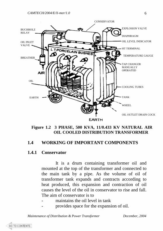
It is a drum containing transformer oil and mounted at the top of the transformer and connected to the main tank by a pipe. As the volume of oil of transformer tank expands and contracts according to heat produced, this expansion and contraction of oil causes the level of the oil in conservator to rise and fall. The aim of conservator is to - maintains the oil level in tank - provides space for the expansion of oil.
EXPLOSION VALVE
DIAPHRAGM
OIL LEVEL INDICATOR
HT TERMINAL
TEMPERATURE GAUGE
TAP CHANGER MANUALLY OPERATED
COOLING TUBES
TANK
WHEEL OIL OUTLET DRAIN COCK
BUCHHOLZ RELAY OIL INLET VALVE BREATHER
OIL
EARTH
Figure 1.2 3 PHASE, 500 KVA, 11/0.433 KV NATURAL AIR OIL COOLED DISTRIBUTION TRANSFORMER
CONSERVATOR
CAMTECH/2004/E/X-mer/1.0
Maintenance of Distribution & Power Transformer December, 2004
7
1.4.2 Breather
It is attached to conservator tank and contains silica gel, which prevents the moist air from entering into the tank during contraction of oil. When oil is hot there is expansion and gas passes to atmosphere through it. When oil is cooled, it contracts and the air enters in it.
It prevents transformer oil from moisture contamination.
1.4.3 Buchholz Relay
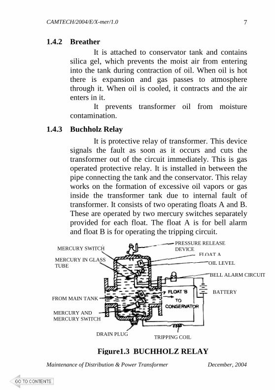
It is protective relay of transformer. This device signals the fault as soon as it occurs and cuts the transformer out of the circuit immediately. This is gas operated protective relay. It is installed in between the pipe connecting the tank and the conservator. This relay works on the formation of excessive oil vapors or gas inside the transformer tank due to internal fault of transformer. It consists of two operating floats A and B. These are operated by two mercury switches separately provided for each float. The float A is for bell alarm and float B is for operating the tripping circuit.
Figure1.3 BUCHHOLZ RELAY
PRESSURE RELEASE DEVICE
FLOAT A
OIL LEVEL
BATTERY
TRIPPING COIL DRAIN PLUG
MERCURY AND MERCURY SWITCH
FROM MAIN TANK
MERCURY IN GLASS TUBE
MERCURY SWITCH
BELL ALARM CIRCUIT
CAMTECH/2004/E/X-mer/1.0
Maintenance of Distribution & Power Transformer December, 2004
8
Whenever there is a minor fault, the bell alarm operated by float ‘A’ indicates shortage of oil or over loading or other minor fault.
When float ‘B’ operates due to excessive gases, then there is severe fault in the transformer. It trips the circuit breaker and transformer is put out of circuit and thus saved.
1.4.4 Explosion Vent
A major fault inside the transformer causes instantaneous vaporization of oil, leading to extremely rapid build up of gaseous pressure. If this pressure is not released with in few milliseconds, the transformer tank can rupture, spilling oil over a wide area. An explosion vent provides instantaneous releasing of such dangerous pressure and protects the transformer.
1.4.5 Oil level Indicator
It indicates level of insulating oil in the transformer tank. It has markings on transparent sheet for maximum & minimum levels.
1.4.6 Inlet Valve
It provides passage to pour the transformer oil in the tank during purification or in case of shortage found in the tank.
1.4.7 Outlet Valve
It provides passage to drain the oil during overhauling or as and when required oil sample for testing.
1.4.8 Cooling Tubes
These tubes provide better and effective cooling of transformer oil by increasing the surface area of tank to the atmosphere.
CAMTECH/2004/E/X-mer/1.0
Maintenance of Distribution & Power Transformer December, 2004
9
1.5 DIFFERENT SYSTEM OF COOLING OF TRANSFORMER
In every machine the losses causes the temperature to rise. In rotating machines, it is easy to cool the machines by providing fans or fledge, but in case of transformer being a stationary machine, cooling is different. To cool the transformer following methods are commonly used:
1.5.1 ONAN Type Cooling
In case of smaller rating of transformers, its tank may be able to dissipate the heat directly to the atmospheric air, whilst bigger ratings may require additional dissipating surface in the form of tubes/ radiators connected to tank or in the form of radiator bank. In these cases, the heat dissipation is from transformer oil to atmospheric air by natural means. This form of cooling is known as ONAN (Oil Natural, Air Natural) type of cooling.
1.5.2 ONAF Type Cooling
For augmenting the rate if dissipation of heat, other means such as fans blowing air on to the cooling surfaces are employed. The forced air take away the heat at a faster rate, thereby giving better cooling rate then natural air. This type of cooling is called ONAF (Oil Natural Air Forced) type of cooling.
1.5.3 OFAF Type Cooling
To obtain better rate of heat dissipation than ONAF type cooling, forced circulation of the oil can be employed. The oil can be forced within the closed loop of transformer tank and cooling equipment by means of pumps. This type of cooling is called OFAF (Oil Forced Air Forced) type of cooling.
CAMTECH/2004/E/X-mer/1.0
Maintenance of Distribution & Power Transformer December, 2004
10
1.6 FACTORS AFFECTING LIFE OF TRANSFORMER
Life of transformer is affected by the following factors:
1. Moisture
2. Oxygen
3. Solid Impurities
4. Varnishes
5. Slackness of winding 1.6.1 Effect of Moisture on Transformer Life
Transformer oil and winding always contain
moisture. Table -1 shows acceptable limits of moisture (in ppm) in transformer oil before and after energizing of the transformer. Presence of moisture in oil is highly undesirable as it affects adversely the dielectric properties of oil. The moisture present in oil also affects the solid insulation of transformer. As paper insulation is highly hygroscopic in nature when transformer is filled with oil, it absorbs the moisture from oil which affects its insulation properties as well as reduces its life. Solubility of moisture in oil increases with increase in temperature and oxidation products of oil. When the oil in service oxidizes, acids are formed. These acids increase moisture solubility of oil. Acids coupled with moisture further decompose the oil forming more acids and moisture. Thus the rate of deterioration of oil increases.
CAMTECH/2004/E/X-mer/1.0
Maintenance of Distribution & Power Transformer December, 2004
11
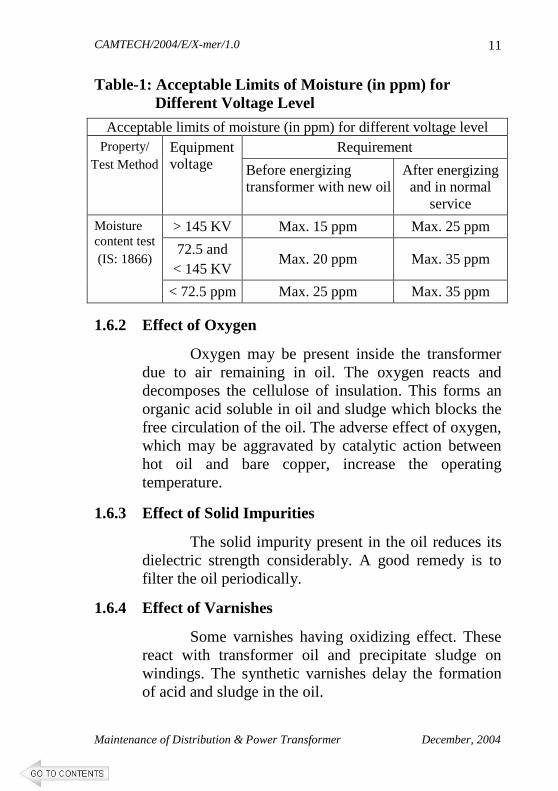
Table-1: Acceptable Limits of Moisture (in ppm) for Different Voltage Level
Acceptable limits of moisture (in ppm) for different voltage level Requirement Property/
Test Method Equipment voltage Before energizing
transformer with new oil After energizing and in normal
service
> 145 KV Max. 15 ppm Max. 25 ppm
72.5 and < 145 KV
Max. 20 ppm Max. 35 ppm
Moisture content test (IS: 1866)
< 72.5 ppm Max. 25 ppm Max. 35 ppm
1.6.2 Effect of Oxygen
Oxygen may be present inside the transformer due to air remaining in oil. The oxygen reacts and decomposes the cellulose of insulation. This forms an organic acid soluble in oil and sludge which blocks the free circulation of the oil. The adverse effect of oxygen, which may be aggravated by catalytic action between hot oil and bare copper, increase the operating temperature.
1.6.3 Effect of Solid Impurities
The solid impurity present in the oil reduces its dielectric strength considerably. A good remedy is to filter the oil periodically.
1.6.4 Effect of Varnishes
Some varnishes having oxidizing effect. These react with transformer oil and precipitate sludge on windings. The synthetic varnishes delay the formation of acid and sludge in the oil.
CAMTECH/2004/E/X-mer/1.0
Maintenance of Distribution & Power Transformer December, 2004
12
1.6.5 Effect of Slackness of Winding After few months of service, the transformer
coils may suffer natural setting. This may wear the conductor insulation. The coils may also get displaced under load or momentary short circuit conditions. This may result in electrical and magnetic unbalance. A good practice is, therefore to lift the core and windings to take away any slackness present.
*****
CAMTECH/2004/E/X-mer/1.0
Maintenance of Distribution & Power Transformer December, 2004
13
CHAPTER 2
MAINTENANCE
The principal object of transformer maintenance is to maintain the insulation in good condition. Moisture, dust and excessive heat are the main reasons of insulation deterioration and avoidance of these will keep insulation in good condition.
The transformer is a most important equipment
installed in a substation which is static in nature. This fact may leads to an impression that it needs no maintenance but this is not true. In many cases faults takes place due to lack of proper maintenance. Maintenance includes regular inspections testing and rectification of defects. Upkeepment of records of each inspection is essential. If any replacement is carried out or adjustment of certain setting is done then these must be entered in a logbook. A rigid system of maintenance will ensure long life, trouble free service of transformer and reduction in unnecessary interruption.
All work on transformer must be carried out under
permit to work system. The “permit to work” is to be issued through permit card only by an authorized person. As the name suggests it authorizes the maintenance supervisor and his team to carry out the work. Furthermore, this card will indicate unambiguously the points at which it is safe to work, the time interval when it is to be done, steps to be taken to ensure safety such as earthing, display of danger notices etc. at the nearest live point. It should have the signature of the authorized person. After the work is completed, the permit card should be cancelled and it should be taken back.
CAMTECH/2004/E/X-mer/1.0
Maintenance of Distribution & Power Transformer December, 2004
14
Danger notices should be put up or removed by the responsible supervisor who will take the charge of keys of equipment, rooms, etc.
2.1 SAFETY PRECAUTIONS DURING MAINTENANCE
Following safety precautions should be observed during maintenance of transformers.
� Ensure all arrangements are safe.
� Isolate the transformer from supply and earth the terminals properly.
� Check & record the oil level in the tank before unseal the tank and unscrew the nuts and bolts.
� Ensure the work place is fire proof, care should be taken to prevent fire.
� Put a caution board “NO SMOKING”.
� The staff should not have anything in his breast pocket and should not wear watch or ring.
2.2 MAINTENANCE PROCEDURE 2.2.1 Oil
� Check oil level at frequent intervals. Leakage of excessive oil to be investigated and repaired as early as possible.
� Maintain the record of make of oil and always prefer the same make of oil for topping up or replacement. The oil of different makes may be separated into layers. The mixture of oil have greater tendency to form acidity or sludge.
� Never use the released oil even if the same make.
CAMTECH/2004/E/X-mer/1.0
Maintenance of Distribution & Power Transformer December, 2004
15
� Never mix the transformer oil to the oil of switchgear equipment.
� Take the oil samples at regular intervals and get tested.
� Only the dielectric strength does not indicate the healthy condition of oil. Therefore in addition to chemical tests other tests such as acidity test, test for polar contaminants, sludge also to be carried out.
� If the acidity exceeds limits, open the cover to ascertain the condition of interior of tank, core and windings. Take suitable action if sludge or corrosion is evident.
2.2.2 Rollers
� Examine the rollers carefully during overhauling and grease them properly.
2.2.3 Transformer Body
� Examine the transformer tank for rust and leaks periodically. Clean the rust, if any and repaint.
� Ensure painting of tank at regular intervals.
� Ensure correct pressure for tightening the nut and bolt at joints. Replace the gaskets as and when opened the gasketed joints.
� Lift the core and windings by means of suitable lifting arrangement in suitable conditions required for internal inspection during overhauling or to rectify defect.
� Measure the insulation resistance without disturbing thing.
CAMTECH/2004/E/X-mer/1.0
Maintenance of Distribution & Power Transformer December, 2004
16
� Properly clean the tank cover before opening it.
� Remove dust, moisture etc. from top.
� The spanner should be cleaned of all metal fillings and to be held by a cotton strap or string tied round the waist or wrist of the staff opening tank cover.
� Remove all nuts and bolts etc., before removing the cover.
� Dismount bushings, if mounted on top. Remove the cover carefully if core and windings are separate. If core and windings are suspended from tank cover, provide eye bolts on the cover for lifting along with core and winding. Care should be taken to ensure vertical removal of the core. After lifting the core, recount and tally the spanners and tools used
2.2.4 Core and Windings
2.2.4.1 Lifting the core and coils
� Remove the fixing devices if core and coils are suspended, from each end near the top.
� Unload the connections of bushings and remove the bushings from tank walls.
� Remove mechanical connection to the tap changing switch handle, if any.
� Remove any earthing strips between the core clamps and tank.
� Lift the core and coils vertically by slinging it from lifting lugs provided on core. Make sure that the sling does not foul against connections, tapping switch etc.
CAMTECH/2004/E/X-mer/1.0
Maintenance of Distribution & Power Transformer December, 2004
17
� Allow the core and coils to drain oil into tank for some time.
� Now lower them on beams placed in a metal tray filled with saw dust or sand.
2.2.4.2 Inspection
� Ensure that everything is intact correctly.
� Leads are not pulled out off their places.
� Ensure tightness of nuts and bolts.
� Clean the sludge by transformer oil and ensure that ducts are not blocked.
� Clamp the windings firmly without any movement. Adjust the vertical tie bars to tighten loose windings or spacers. Properly tight the special coil adjustment bolt, if provided.
� Check the proper operation of tap changing switch.
� Tight all connections.
� Conduct insulation resistance test and take the corrective action.
� Remove sludge deposition at the bottom of tank. 2.2.5 Bushings
� Clean the bushing porcelain and examine for cracks
and chips. Replace if required.
� If the bushing is below oil level, lower the oil until it is below the bushing hole.
� If only the porcelain is to be changed it may not be necessary to undo the internal bushing connection,
CAMTECH/2004/E/X-mer/1.0
Maintenance of Distribution & Power Transformer December, 2004
18
for, in some cases the bushing stems are joined by an insulated bar to prevent them from turning when the nuts are undone. All the nuts at the top of the bushing should be removed and the old porcelain lifted straight up over the central stem, which remain in place. Slide the new porcelain down over the stem and tighten the nuts. Too much strain on the porcelain should not be applied when tightening the connections. Change only one porcelain at a time. If the insulated bar between the bushing stems is not provided, the internal connections should be undone and the whole bushing removed before the porcelain is changed and then replace the porcelain.
� When a complete bushing is to be changed the
internal connection to the bushing should be undone. If the replacement bushing has a socket at the bottom end, the old bushing should be unclamped and withdrawn from the tank. Now unplug the flexible lead from the old bushing and plugged into the new one, which is then lowered into the hole in the tank and reclamped firmly but not too tightly.
2.2.6 Cable Boxes
� Check the sealing arrangement for filling holes
yearly.
� Examine the plug, change bituminous compound if cracked to avoid accumulation of water around the plug.
� Examine gasket joints and tighten if required.
CAMTECH/2004/E/X-mer/1.0
Maintenance of Distribution & Power Transformer December, 2004
19
2.2.7 External Connection � Tight all connections.
� Undo connection, clean them with emery paper if they appear blackened or corroded.
� Remake the connection and provide a heavy coat of grease.
� The bluish tinge characteristic of metal indicates over heating, then the connections should not be considered satisfactory. Either it become loose or dirty or the size of conductor is not suitable for carrying current.
� A small copper loop to bridge the top cover of the transformer and the tank may also be provided to avoid earth fault current passing through the fastening bolts when there is a lighting surge, high voltage surge or failure of bushings.
2.2.8 Conservator and Magnetic Oil Gauge
� Clean or flush inside of conservator with oil every
two to three years. For this purpose a removable end is provided.
� The oil level indicator should always be kept clean.
� Replace the broken transparent material of level indicator immediately.
� Examine the mechanism of oil gauge functioning properly during cleaning of conservator.
CAMTECH/2004/E/X-mer/1.0
Maintenance of Distribution & Power Transformer December, 2004
20
2.2.9 Breather
There are generally two types of breathers used on a transformer:
a. Plain breather b. Silica gel breather
� The end of the plain breather should be kept clean and the ventilation holes free of dust. If an oil seal has been provided, the oil should be wiped out.
� Silica gel dehydrating breathers are fitted with a sight glass so that the colour of the crystals may be seen. The colour changes from blue to pink as the crystals absorb moisture. When the crystals get saturated with moisture they become predominantly pink and should therefore be reactivated. The body of the breather should be removed by undoing the nuts. If the crystals have been kept in an inner container, the container should be removed, but if they are not, the crystals should be removed into a shallow tray. The crystals should be backed at a temperature of about 200°C until the whole mass is restored blue colour. Clean the breather and place the dry and blue crystals. Renew the oil in the sealing cup at the bottom.
2.2.10 Buchholtz Relay
� During operation if gas is found to be collecting and giving alarm, the gas should be tested and analysed to find out the nature of fault. Sometimes, it is noticed that the gas collecting is only air. The reasons for this may be that the oil is releasing any absorbed air due to change in temperature or due to leakage on the suction side of pump. The absorbed air is released in initial stages only when no
CAMTECH/2004/E/X-mer/1.0
Maintenance of Distribution & Power Transformer December, 2004
21
vacuum is applied during filling of oil. The internal faults can be identified to a great extent by a chemical analysis of gas.
� Routine operation and mechanical inspection/tests should be carried out at one and two yearly intervals respectively.
� The operation is tested by injecting air into the relay through the lower petcock of a double float relay for the 45° petcock of a single float relay. After inspection, any air which has accumulated in the upper gas chamber must be released by the upper petcock, by filling the chamber with oil.
� To carry out mechanical inspection, the oil level must be brought below the level of relay. Both floats should be able to rise and fall freely. Relay should give alarm/trip due to the oil level falling below the Buchholtz level. The mercury switches should be tightly clamped. If the glass of a mercury switch is cracked, it must be replaced.
2.2.11 Explosion Vent
� Frequently inspect diaphragm of the vent and replace if required.
� An investigation should be carried out to determine the nature and cause of the fault before replacing the broken diaphragm.
2.2.12 Gaskets
� Check the tightness of all bolts fastening gasketed joints. To avoid uneven pressure, the bolts should be tightened evenly round the joints. Leaking gaskets should be replaced as soon as the circumstances permit.
CAMTECH/2004/E/X-mer/1.0
Maintenance of Distribution & Power Transformer December, 2004
22
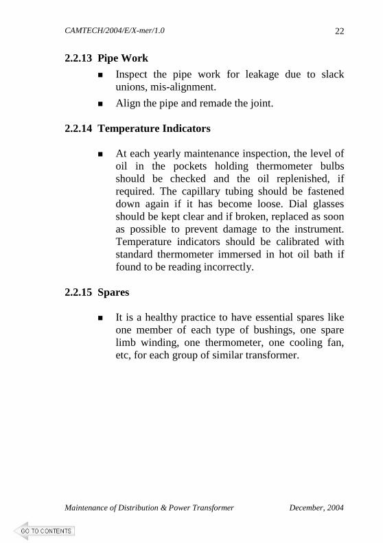
2.2.13 Pipe Work
� Inspect the pipe work for leakage due to slack unions, mis-alignment.
� Align the pipe and remade the joint. 2.2.14 Temperature Indicators
� At each yearly maintenance inspection, the level of oil in the pockets holding thermometer bulbs should be checked and the oil replenished, if required. The capillary tubing should be fastened down again if it has become loose. Dial glasses should be kept clear and if broken, replaced as soon as possible to prevent damage to the instrument. Temperature indicators should be calibrated with standard thermometer immersed in hot oil bath if found to be reading incorrectly.
2.2.15 Spares
� It is a healthy practice to have essential spares like
one member of each type of bushings, one spare limb winding, one thermometer, one cooling fan, etc, for each group of similar transformer.
CAMTECH/2004/E/X-mer/1.0
Maintenance of Distribution & Power Transformer December, 2004
23
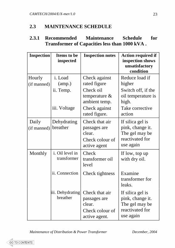
2.3 MAINTENANCE SCHEDULE 2.3.1 Recommended Maintenance Schedule for
Transformer of Capacities less than 1000 kVA . Inspection
Items to be inspected
Inspection notes Action required if inspection shows unsatisfactory
condition
Hourly (if manned)
i. Load (amp.)
ii. Temp.
iii. Voltage
Check against rated figure Check oil temperature & ambient temp. Check against rated figure.
Reduce load if higher Switch off, if the oil temperature is high. Take corrective action
Daily (if manned)
Dehydrating breather
Check that air passages are clear. Check colour of active agent
If silica gel is pink, change it. The gel may be reactivated for use again
i. Oil level in transformer
Check transformer oil level
If low, top up with dry oil.
ii. Connection Check tightness Examine transformer for leaks.
Monthly
iii. Dehydrating breather
Check that air passages are clear. Check colour of active agent.
If silica gel is pink, change it. The gel may be reactivated for use again
CAMTECH/2004/E/X-mer/1.0
Maintenance of Distribution & Power Transformer December, 2004
24
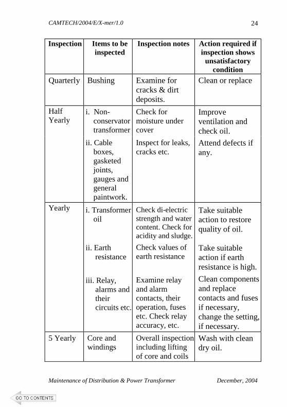
Inspection
Items to be inspected
Inspection notes Action required if inspection shows unsatisfactory
condition
Quarterly Bushing Examine for cracks & dirt deposits.
Clean or replace
i. Non- conservator transformer
Check for moisture under cover
Improve ventilation and check oil.
Half Yearly
ii. Cable boxes, gasketed joints, gauges and general paintwork.
Inspect for leaks, cracks etc.
Attend defects if any.
Yearly i. Transformer oil
ii. Earth resistance
iii. Relay, alarms and their circuits etc.
Check di-electric strength and water content. Check for acidity and sludge.
Check values of earth resistance
Examine relay and alarm contacts, their operation, fuses etc. Check relay accuracy, etc.
Take suitable action to restore quality of oil.
Take suitable action if earth resistance is high.
Clean components and replace contacts and fuses if necessary, change the setting, if necessary.
5 Yearly Core and windings
Overall inspection including lifting of core and coils
Wash with clean dry oil.
CAMTECH/2004/E/X-mer/1.0
Maintenance of Distribution & Power Transformer December, 2004
25
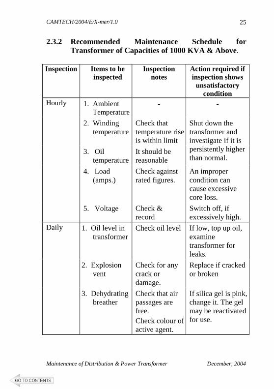
2.3.2 Recommended Maintenance Schedule for Transformer of Capacities of 1000 KVA & Above.
Inspection Items to be
inspected Inspection
notes Action required if inspection shows unsatisfactory
condition 1. Ambient
Temperature - -
2. Winding temperature
Check that temperature rise is within limit
3. Oil temperature
It should be reasonable
Shut down the transformer and investigate if it is persistently higher than normal.
4. Load (amps.)
Check against rated figures.
An improper condition can cause excessive core loss.
Hourly
5. Voltage Check & record
Switch off, if excessively high.
1. Oil level in transformer
Check oil level If low, top up oil, examine transformer for leaks.
2. Explosion vent
Check for any crack or damage.
Replace if cracked or broken
Daily
3. Dehydrating breather
Check that air passages are free. Check colour of active agent.
If silica gel is pink, change it. The gel may be reactivated for use.
CAMTECH/2004/E/X-mer/1.0
Maintenance of Distribution & Power Transformer December, 2004
26
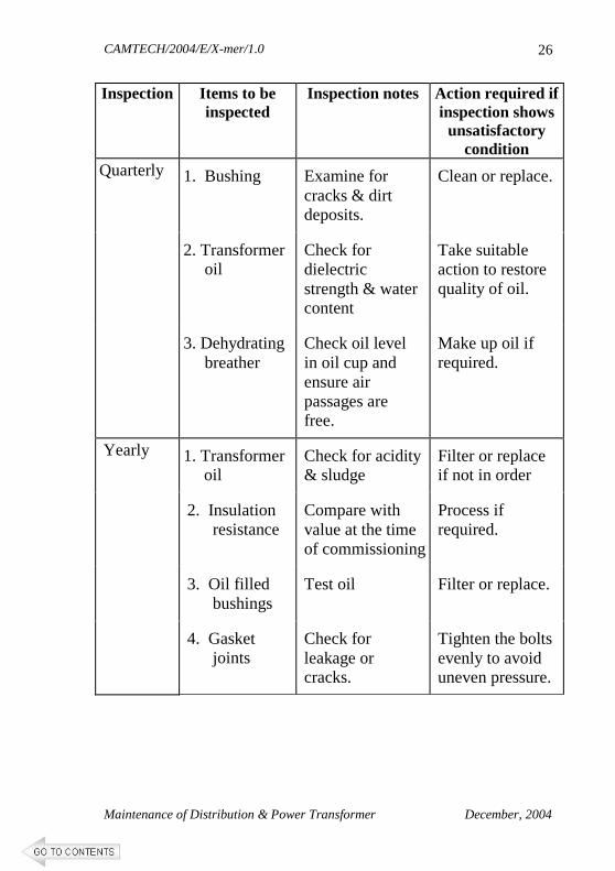
Inspection Items to be inspected
Inspection notes Action required if inspection shows unsatisfactory
condition
1. Bushing Examine for cracks & dirt deposits.
Clean or replace.
2. Transformer oil
Check for dielectric strength & water content
Take suitable action to restore quality of oil.
Quarterly
3. Dehydrating breather
Check oil level in oil cup and ensure air passages are free.
Make up oil if required.
1. Transformer oil
Check for acidity & sludge
Filter or replace if not in order
2. Insulation resistance
Compare with value at the time of commissioning
Process if required.
3. Oil filled bushings
Test oil Filter or replace.
Yearly
4. Gasket joints
Check for leakage or cracks.
Tighten the bolts evenly to avoid uneven pressure.
CAMTECH/2004/E/X-mer/1.0
Maintenance of Distribution & Power Transformer December, 2004
27
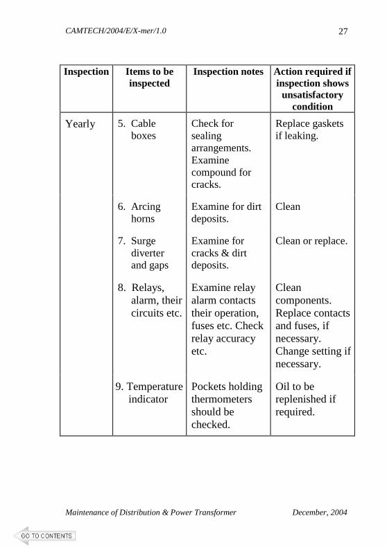
Inspection Items to be
inspected Inspection notes Action required if
inspection shows unsatisfactory
condition
5. Cable boxes
Check for sealing arrangements. Examine compound for cracks.
Replace gaskets if leaking.
6. Arcing horns
Examine for dirt deposits.
Clean
7. Surge diverter and gaps
Examine for cracks & dirt deposits.
Clean or replace.
8. Relays, alarm, their circuits etc.
Examine relay alarm contacts their operation, fuses etc. Check relay accuracy etc.
Clean components. Replace contacts and fuses, if necessary. Change setting if necessary.
Yearly
9. Temperature indicator
Pockets holding thermometers should be checked.
Oil to be replenished if required.
CAMTECH/2004/E/X-mer/1.0
Maintenance of Distribution & Power Transformer December, 2004
28
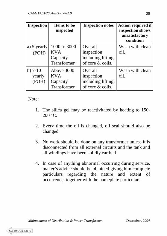
Inspection Items to be inspected
Inspection notes Action required if inspection shows unsatisfactory
condition
a) 5 yearly (POH)
1000 to 3000 KVA Capacity Transformer
Overall inspection including lifting of core & coils.
Wash with clean oil.
b) 7-10 yearly (POH)
Above 3000 KVA Capacity Transformer
Overall inspection including lifting of core & coils.
Wash with clean oil.
Note:
1. The silica gel may be reactivitated by heating to 150-200° C.
2. Every time the oil is changed, oil seal should also be
changed.
3. No work should be done on any transformer unless it is disconnected from all external circuits and the tank and all windings have been solidly earthed.
4. In case of anything abnormal occurring during service,
maker’s advice should be obtained giving him complete particulars regarding the nature and extent of occurrence, together with the nameplate particulars.
CAMTECH/2004/E/X-mer/1.0
Maintenance of Distribution & Power Transformer December, 2004
29
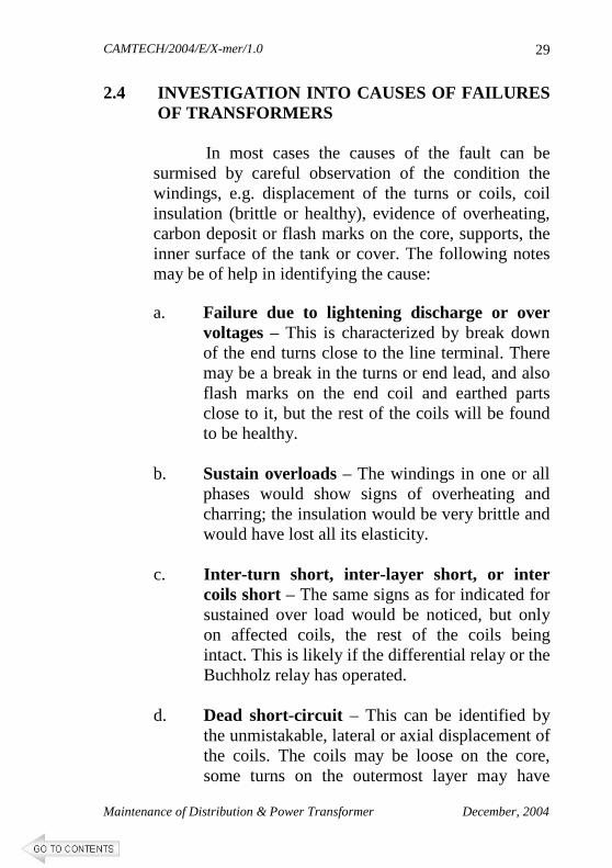
2.4 INVESTIGATION INTO CAUSES OF FAILURES OF TRANSFORMERS
In most cases the causes of the fault can be surmised by careful observation of the condition the windings, e.g. displacement of the turns or coils, coil insulation (brittle or healthy), evidence of overheating, carbon deposit or flash marks on the core, supports, the inner surface of the tank or cover. The following notes may be of help in identifying the cause:
a. Failure due to lightening discharge or over
voltages – This is characterized by break down of the end turns close to the line terminal. There may be a break in the turns or end lead, and also flash marks on the end coil and earthed parts close to it, but the rest of the coils will be found to be healthy.
b. Sustain overloads – The windings in one or all
phases would show signs of overheating and charring; the insulation would be very brittle and would have lost all its elasticity.
c. Inter-turn short, inter-layer short, or inter
coils short – The same signs as for indicated for sustained over load would be noticed, but only on affected coils, the rest of the coils being intact. This is likely if the differential relay or the Buchholz relay has operated.
d. Dead short-circuit – This can be identified by
the unmistakable, lateral or axial displacement of the coils. The coils may be loose on the core, some turns on the outermost layer may have
CAMTECH/2004/E/X-mer/1.0
Maintenance of Distribution & Power Transformer December, 2004
30
burst outwards and broken as if under tension. If, in addition to these signs, the windings are also completely charred, it is conclusive evidence that the short circuit has continued for an appreciable period, not having been cleared quickly by the protective relays.
e. If the upper chamber of the Buchholz relay alone
has tripped, check the insulation of core bolts, by applying a voltage of 230V to 1000V between the core and each bolt. If it fails, renew the insulating bush. Observe also all the joints, and tap-changer contacts, for over-heating and arcing.
f. If the oil shows a low BDV, it does not
necessarily mean it has caused the breakdown. At high voltage ratings, excessive moisture content in the oil may result an internal flashover between the live parts and earth, which all leave corresponding tell tale marks.
*****
CAMTECH/2004/E/X-mer/1.0
Maintenance of Distribution & Power Transformer December, 2004
31
CHAPTER 3
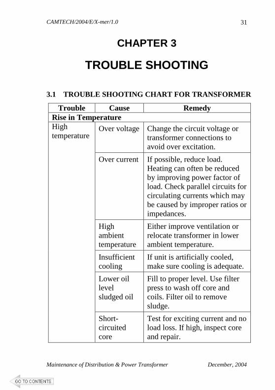
TROUBLE SHOOTING 3.1 TROUBLE SHOOTING CHART FOR TRANSFORMER
Trouble Cause Remedy Rise in Temperature
Over voltage Change the circuit voltage or transformer connections to avoid over excitation.
Over current If possible, reduce load. Heating can often be reduced by improving power factor of load. Check parallel circuits for circulating currents which may be caused by improper ratios or impedances.
High ambient temperature
Either improve ventilation or relocate transformer in lower ambient temperature.
Insufficient cooling
If unit is artificially cooled, make sure cooling is adequate.
Lower oil level sludged oil
Fill to proper level. Use filter press to wash off core and coils. Filter oil to remove sludge.
High temperature
Short-circuited core
Test for exciting current and no load loss. If high, inspect core and repair.
CAMTECH/2004/E/X-mer/1.0
Maintenance of Distribution & Power Transformer December, 2004
32
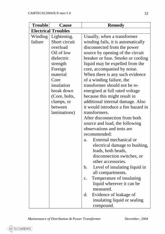
Trouble Cause Remedy Electrical Troubles
Lightening. Short circuit overload Oil of low dielectric strength Foreign material Core insulation break down (Core, bolts, clamps, or between laminations)
Usually, when a transformer winding fails, it is automatically disconnected from the power source by opening of the circuit breaker or fuse. Smoke or cooling liquid may be expelled from the core, accompanied by noise. When there is any such evidence of a winding failure, the transformer should not be re-energised at full rated voltage because this might result in additional internal damage. Also it would introduce a fire hazard in transformers. After disconnection from both source and load, the following observations and tests are recommended:
a. External mechanical or electrical damage to bushing, leads, both heads, disconnection switches, or other accessories.
b. Level of insulating liquid in all compartments.
c. Temperature of insulating liquid wherever it can be measured.
Winding failure
d. Evidence of leakage of insulating liquid or sealing compound.
CAMTECH/2004/E/X-mer/1.0
Maintenance of Distribution & Power Transformer December, 2004
33
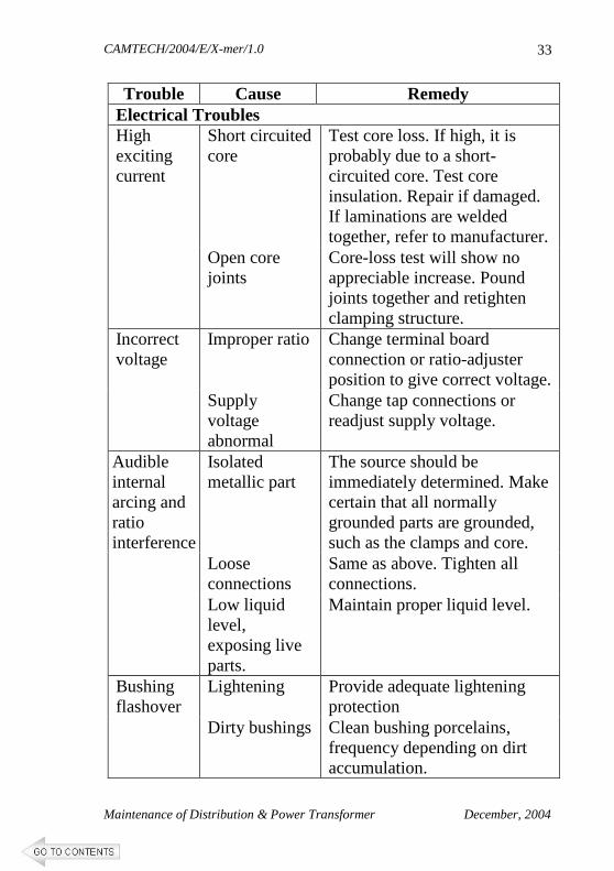
Trouble Cause Remedy Electrical Troubles
Short circuited core
Test core loss. If high, it is probably due to a short-circuited core. Test core insulation. Repair if damaged. If laminations are welded together, refer to manufacturer.
High exciting current
Open core joints
Core-loss test will show no appreciable increase. Pound joints together and retighten clamping structure.
Improper ratio Change terminal board connection or ratio-adjuster position to give correct voltage.
Incorrect voltage
Supply voltage abnormal
Change tap connections or readjust supply voltage.
Isolated metallic part
The source should be immediately determined. Make certain that all normally grounded parts are grounded, such as the clamps and core.
Loose connections
Same as above. Tighten all connections.
Audible internal arcing and ratio interference
Low liquid level, exposing live parts.
Maintain proper liquid level.
Lightening Provide adequate lightening protection
Bushing flashover
Dirty bushings Clean bushing porcelains, frequency depending on dirt accumulation.
CAMTECH/2004/E/X-mer/1.0
Maintenance of Distribution & Power Transformer December, 2004
34
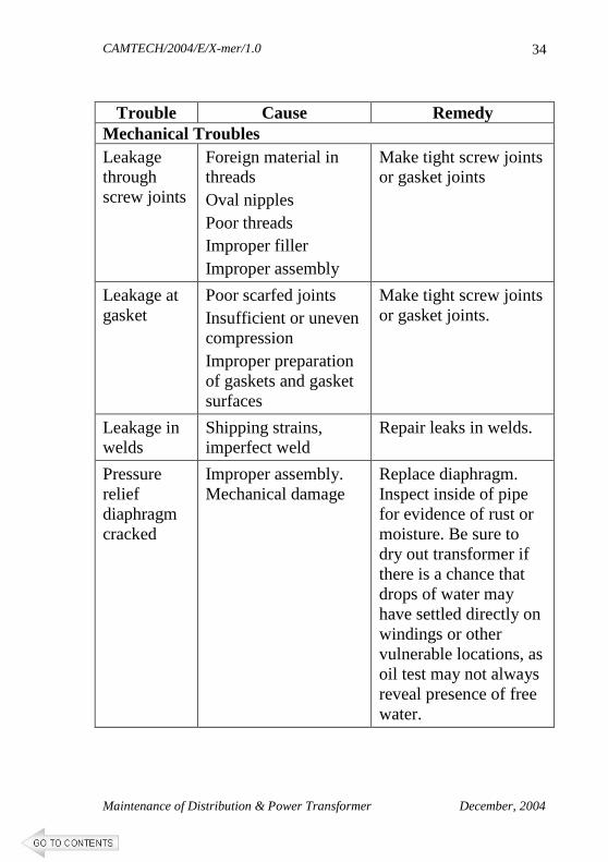
Trouble Cause Remedy
Mechanical Troubles Leakage through screw joints
Foreign material in threads Oval nipples Poor threads Improper filler Improper assembly
Make tight screw joints or gasket joints
Leakage at gasket
Poor scarfed joints Insufficient or uneven compression Improper preparation of gaskets and gasket surfaces
Make tight screw joints or gasket joints.
Leakage in welds
Shipping strains, imperfect weld
Repair leaks in welds.
Pressure relief diaphragm cracked
Improper assembly. Mechanical damage
Replace diaphragm. Inspect inside of pipe for evidence of rust or moisture. Be sure to dry out transformer if there is a chance that drops of water may have settled directly on windings or other vulnerable locations, as oil test may not always reveal presence of free water.
CAMTECH/2004/E/X-mer/1.0
Maintenance of Distribution & Power Transformer December, 2004
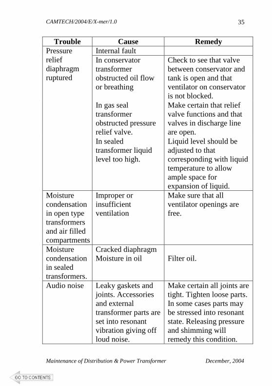
35
Trouble Cause Remedy Internal fault In conservator transformer obstructed oil flow or breathing
Check to see that valve between conservator and tank is open and that ventilator on conservator is not blocked.
In gas seal transformer obstructed pressure relief valve.
Make certain that relief valve functions and that valves in discharge line are open.
Pressure relief diaphragm ruptured
In sealed transformer liquid level too high.
Liquid level should be adjusted to that corresponding with liquid temperature to allow ample space for expansion of liquid.
Moisture condensation in open type transformers and air filled compartments
Improper or insufficient ventilation
Make sure that all ventilator openings are free.
Moisture condensation in sealed transformers.
Cracked diaphragm Moisture in oil
Filter oil.
Audio noise Leaky gaskets and joints. Accessories and external transformer parts are set into resonant vibration giving off loud noise.
Make certain all joints are tight. Tighten loose parts. In some cases parts may be stressed into resonant state. Releasing pressure and shimming will remedy this condition.
CAMTECH/2004/E/X-mer/1.0
Maintenance of Distribution & Power Transformer December, 2004
36
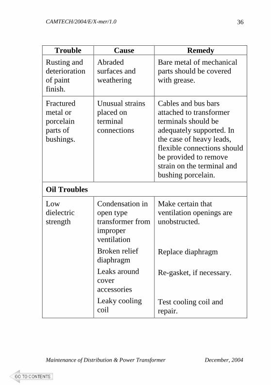
Trouble Cause Remedy
Rusting and deterioration of paint finish.
Abraded surfaces and weathering
Bare metal of mechanical parts should be covered with grease.
Fractured metal or porcelain parts of bushings.
Unusual strains placed on terminal connections
Cables and bus bars attached to transformer terminals should be adequately supported. In the case of heavy leads, flexible connections should be provided to remove strain on the terminal and bushing porcelain.
Oil Troubles
Low dielectric strength
Condensation in open type transformer from improper ventilation
Broken relief diaphragm
Leaks around cover accessories
Leaky cooling coil
Make certain that ventilation openings are unobstructed.
Replace diaphragm
Re-gasket, if necessary.
Test cooling coil and repair.
CAMTECH/2004/E/X-mer/1.0
Maintenance of Distribution & Power Transformer December, 2004
37
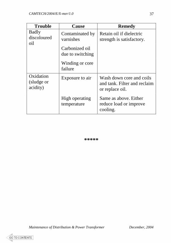
Trouble Cause Remedy
Contaminated by varnishes
Carbonized oil due to switching
Badly discoloured oil
Winding or core failure
Retain oil if dielectric strength is satisfactory.
Exposure to air Wash down core and coils and tank. Filter and reclaim or replace oil.
Oxidation (sludge or acidity)
High operating temperature
Same as above. Either reduce load or improve cooling.
*****
CAMTECH/2004/E/X-mer/1.0
Maintenance of Distribution & Power Transformer December, 2004
38
CHAPTER 4
CHARACTERISTICS OF TRANSFORMER OIL
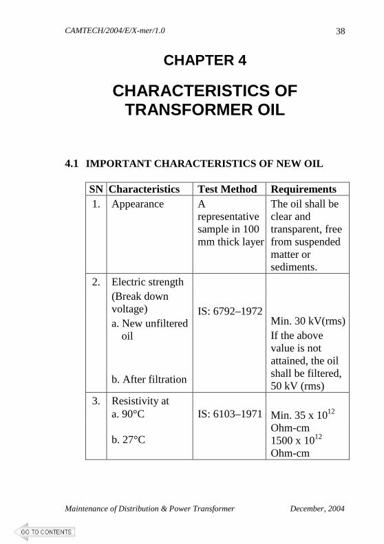
4.1 IMPORTANT CHARACTERISTICS OF NEW OIL
SN Characteristics Test Method Requirements 1. Appearance A
representative sample in 100 mm thick layer
The oil shall be clear and transparent, free from suspended matter or sediments.
IS: 6792–1972
2. Electric strength (Break down voltage) a. New unfiltered
oil b. After filtration
Min. 30 kV(rms) If the above value is not attained, the oil shall be filtered, 50 kV (rms)
Resistivity at a. 90°C IS: 6103–1971
3.
b. 27°C
Min. 35 x 1012 Ohm-cm 1500 x 1012 Ohm-cm
CAMTECH/2004/E/X-mer/1.0
Maintenance of Distribution & Power Transformer December, 2004
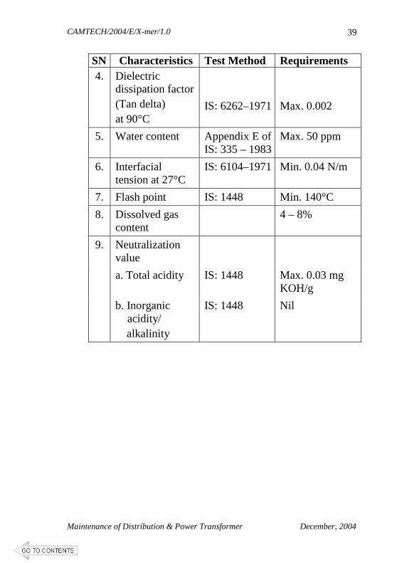
39
SN Characteristics Test Method Requirements 4. Dielectric
dissipation factor (Tan delta) at 90°C
IS: 6262–1971
Max. 0.002
5. Water content Appendix E of IS: 335 – 1983
Max. 50 ppm
6. Interfacial tension at 27°C
IS: 6104–1971 Min. 0.04 N/m
7. Flash point IS: 1448 Min. 140°C
8. Dissolved gas content
4 – 8%
Neutralization value
a. Total acidity IS: 1448 Max. 0.03 mg KOH/g
9.
b. Inorganic acidity/
alkalinity
IS: 1448 Nil
CAMTECH/2004/E/X-mer/1.0
Maintenance of Distribution & Power Transformer December, 2004
40
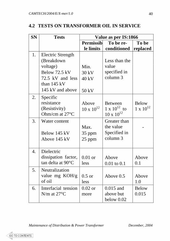
4.2 TESTS ON TRANSFORMER OIL IN SERVICE
Value as per IS:1866 SN Tests Permissible limits
To be re-conditioned
To be replaced
Less than the value specified in column 3
1. Electric Strength (Breakdown voltage) Below 72.5 kV 72.5 kV and less than 145 kV 145 kV and above
Min. 30 kV 40 kV 50 kV
2. Specific resistance (Resistivity) Ohm/cm at 27°C
Above 10 x 1012
Between 1 x 10¹² to 10 x 1012
Below 1 x 10¹²
Greater than the value Specified in column 3
3. Water content Below 145 kV Above 145 kV
Max. 35 ppm 25 ppm
-
4. Dielectric dissipation factor, tan delta at 90°C
0.01 or less
Above 0.01 to 0.1
Above 0.1
5. Neutralization value mg KOH/g of oil
0.5 or less
Above 0.5
Above 1.0
6. Interfacial tension N/m at 27°C
0.02 or more
0.015 and above but below 0.02
Below 0.015
CAMTECH/2004/E/X-mer/1.0
Maintenance of Distribution & Power Transformer December, 2004
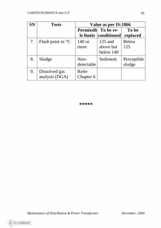
41
Value as per IS:1866 SN Tests Permissible limits
To be re-conditioned
To be replaced
7. Flash point in °C 140 or more
125 and above but below 140
Below 125
8. Sludge Non-detectable
Sediment Perceptible sludge
9. Dissolved gas analysis (DGA)
Refer Chapter 6
*****
CAMTECH/2004/E/X-mer/1.0
Maintenance of Distribution & Power Transformer December, 2004
42
CHAPTER 5
PURIFICATION OF TRANSFORMER OIL
The object of oil purification is to remove all contaminants such as water, carbon deposits, dirt, sludge, dissolved moisture and gases. The most important quality to be preserved is the di-electric strength, which is affected by the presence of moisture.
The insulating materials used in the winding are
hygroscopic by nature and therefore moisture is absorbed through defective breathers, gaskets and addition of untreated make up oil. It is essential to remove these impurities by purifying the oil when the dielectric strength goes below the permissible limits.
The purification plant should be capable of removing
dissolved air/moisture in the form of free and finely dispersed water vapour and moisture in solution, sludge and fibres, gases, carbonaceous products formed due to arcing and drum scale or any other solid particles from insulating oil.
CAMTECH/2004/E/X-mer/1.0
Maintenance of Distribution & Power Transformer December, 2004
43
The plant should be capable of purifying the rated
capacity of transformer oil to the following parameters in maximum three phases.
a. Suspended impurities – maximum 1 micron
particle size.
b. Water content – from 100 ppm to less than 5 ppm
c. Gas removal – from fully saturated i.e. 10to 12% by volume with air/gas down to less than 0.25%
d. Acidity correction – with addition of clay
filters the neutralization index should go down from 0.5 to 0.05 mg KOH/ gm of oil.
e. Dielectric strength – Minimum 60 kV
f. Dissipation factor of oil/ Tan delta at 90°C – 0.002
The switching ON & OFF of the heater groups
should be thermostatically controlled so that the temperature of the oil during treatment is not be permitted to rise above 60°C. Operating vacuum should be better than 1 torr.
CAMTECH/2004/E/X-mer/1.0
Maintenance of Distribution & Power Transformer December, 2004
44
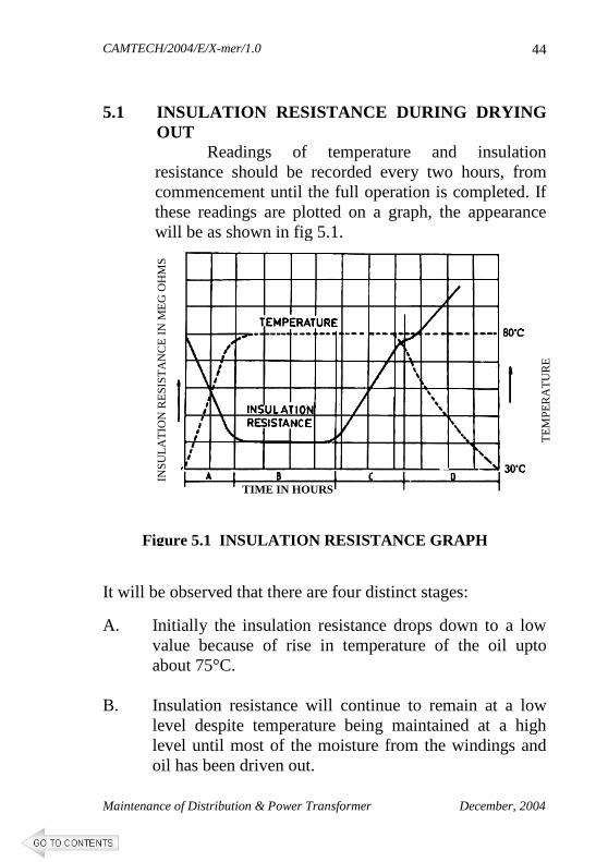
5.1 INSULATION RESISTANCE DURING DRYING
OUT Readings of temperature and insulation
resistance should be recorded every two hours, from commencement until the full operation is completed. If these readings are plotted on a graph, the appearance will be as shown in fig 5.1.
It will be observed that there are four distinct stages:
A. Initially the insulation resistance drops down to a low value because of rise in temperature of the oil upto about 75°C.
B. Insulation resistance will continue to remain at a low
level despite temperature being maintained at a high level until most of the moisture from the windings and oil has been driven out.
Figure 5.1 INSULATION RESISTANCE GRAPH
INS
ULA
TIO
N R
ES
IST
AN
CE
IN M
EG
OH
MS
TE
MP
ER
AT
UR
E
TIME IN HOURS
CAMTECH/2004/E/X-mer/1.0
Maintenance of Distribution & Power Transformer December, 2004
45
C. The insulation resistance will thereafter rise gradually
and level off, indicating that all moisture has been driven out and the drying out operation has been completed. At this point oil circulation should be discontinued.
D. As the oil cools off, the insulation resistance will rise
much above the leveling off point at the end stage (C). This is because the insulation resistance value doubles for a fall in temperature of about 10°C to 15°C.
*****
CAMTECH/2004/E/X-mer/1.0
Maintenance of Distribution & Power Transformer December, 2004
46
CHAPTER 6
CONDITION MONITORING 6.1 INTRODUCTION
Condition monitoring by dissolved gas analysis (DGA) technique is a powerful diagnostic technique for monitoring the internal condition of transformer. It is capable of detecting faults in the incipient stage, before they develop into major faults and result in the outage of the transformer. The conventional Buchholz Relay is universally used in transformers to protect against severe damages. However, its limitation is that enough gas must be generated first to saturate the oil fully and then to come out or there should be a gas surge to operate this relay. Moreover, Buchholz Relay is never meant to be a diagnostic device for preventive maintenance of transformers.
The DGA technique is very sensitive as it
detects gas in parts per million (ppm) of the oil by use of the GAS CHROMATOGRAPH. It is possible to check whether a transformer under service is being subjected to a normal aging and heating or whether there are incipient defects such as hot spots, arcing, overheating or partial discharges. Such incipient faults otherwise remain undetected until they develop into a major failure.
CAMTECH/2004/E/X-mer/1.0
Maintenance of Distribution & Power Transformer December, 2004
47
6.2 FORMATION OF GASES IN OIL FILLED TRANSFORMERS
It is well known that insulating oil in high voltage equipment can break down under the influence of the thermal, electrical stresses to produce hydro carbon gases, hydrogen and carbon oxides. Gases may be formed in transformers and other high voltage oil filled equipment due to aging and to a greater extent as a result of faults. The accumulation of gases in transformer oil may be sudden due to a severe arcing fault or more gradual as in the case of slow deterioration of insulation. The principle mechanism of gas formation in a transformer tank can be classified as under:
6.2.1 Oxidation
Carbon dioxide is the gas predominantly liberated during the process of oxidation. The process begins when small quantities of oil combine chemically with the dissolved oxygen in the oil resulting in formation of traces of organic acids. These acids react with the metal of the transformer, forming metal-based soaps, which dissolve in the oil and act as a catalyst to accelerate the process of oxidation.
6.2.2 Vapourisation
The vapourisation of oil occurs at about 280°C while that for water occurs at about 100°C. The false alarm of a Buchholz relay may be attributed to the fact that the consideration of water vapour takes place when the excess moisture in the tank is vapourized by a heat source. False alarm can also occur, when hydrocarbons, the constituents of the insulating oil, vapourize.
CAMTECH/2004/E/X-mer/1.0
Maintenance of Distribution & Power Transformer December, 2004
48
6.2.3 Insulating Decomposition
The solid insulants in transformers are mainly of cellulose or resinous type, viz., paper, pressboard, cotton, resins and varnishes. These substances contain in their molecular structure substantial amounts of oxygen, carbon and hydrogen. In the temperature range of 150°C to 400°C, the insulation breakdown results in liberation of hydrogen, carbon dioxide and carbon monoxide. Above 400°C, the gases formed are relatively less.
6.2.4 Oil Break Down
The direct break down of oil by arcing results in cracking of the oil. The aromatic contents breakdown into simple hydrocarbon gases and hydrogen. Acetylene and methane are the major constituents. Other hydrocarbon gases may also be liberated due to cracking, if the necessary temperature is maintained for their stable formation.
6.2.5 Electrolytic Action
Hydrogen and oxygen are liberated during electrolytic action. Presence of minute and small particles of fibres within the oil leads to electrolytic action. Light hydrocarbon gases may also be present, if solid insulation is involved.
CAMTECH/2004/E/X-mer/1.0
Maintenance of Distribution & Power Transformer December, 2004
49
6.3 TYPES OF FAULT CONDITIONS
There are three main types of faults viz. overheating of windings, core and joints, partial discharges and arcing.
6.3.1 Overheating
Overheating metallic parts heat up the surrounding regions such as paper insulating tapes and oil. This leads to thermal deterioration of these materials. Thermal degradation of paper produces carbon dioxide, carbon monoxide and water. The ratio of carbon dioxide to carbon monoxide is typically five; but if the ratio falls below three, there is indication of severe overheating of the paper. Oil degradation produces a number of hydrocarbon gases such as methane, ethane, ethylene and acetylene. Methane and ethane are decomposition products that appear above 120°C, ethylene appears above 150°C while acetylene is a high temperature product, appearing at several hundred degrees centigrade. Some hydrogen is also produced alongwith the hydro-carbon gases. The proportion of the various hydrocarbons varies with temperature.
6.3.2 Partial Discharge
Partial discharge occurs due to ionization of oil in highly stressed areas where gas/vapour filled voids are present or the insulation is containing moisture. The main product during partial discharge is hydrogen, though small amounts of methane and other gases would also be present depending upon thermal
CAMTECH/2004/E/X-mer/1.0
Maintenance of Distribution & Power Transformer December, 2004
50
degradation. The disintegration of oil and cellulose due to partial discharge is characterized by the removal of the outer hydrogen atoms to form hydrogen gas. The remaining molecular framework polymerizes and long chain products such as waxes are formed. Thermal degradation is a more predictable phenomenon which involves the break up of chemical bonds. Cellulose decomposes ultimately to CO, CO2 and water. Oil break up into lower molecular hydrocarbons.
6.3.3 Arcing
Arcing can occur between leads, between lead and coil and between other highly stressed regions weakened by fault conditions. The high temperatures caused by arcing results in the production of acetylene and hydrogen. Pattern of generation of gases in transformer is summarized below:
FAULT/PATTERN KEY GAS
Conductor overheating CO/CO2 (Carbon dioxide)
Oil overheating C2H4 (Ethylene)
Partial discharge H2(Hydrogen)
Arcing C2H2(Acetylene)
6.4 SOLUBILITY OF GASES
The solubility of gases in oil varies with temperature and pressure. While solubility of H2, N2, CO, O2 in oil increase with temperature and that of CO2, C2H2, C2H4 and C2H6 decreases with temperature, solubility of CH4 remains essentially constant.
CAMTECH/2004/E/X-mer/1.0
Maintenance of Distribution & Power Transformer December, 2004
51
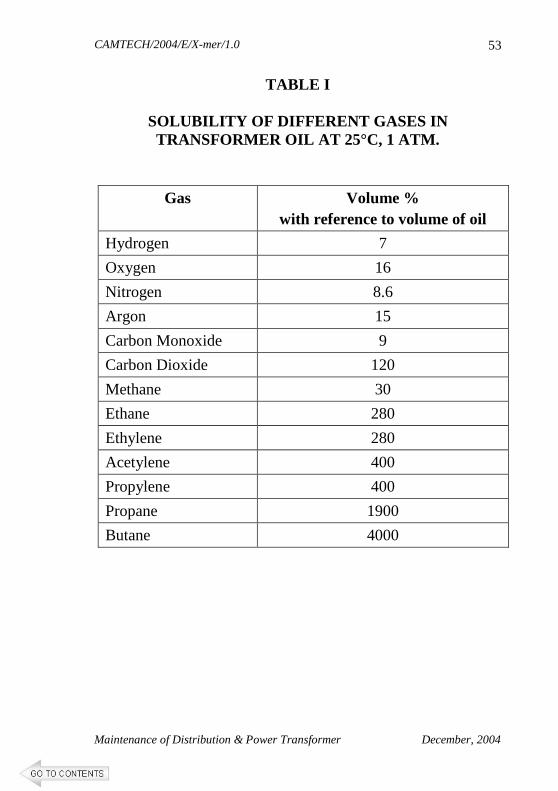
All the gases become more soluble in oil with increase in pressure. Solubility of gas is one of the factors contributing to the complexities in formulating permissible levels of gases on the basis of service life of a transformer. Table I show solubility of different gases 25°C and at 1 atm. The homogeneity of the gases in the oil is dependent on the rate of gas generation, access of the fault area to flowing oil, rate of oil mixing and presence of gas blanket.
6.5 DISSOLVED GAS ANALYSIS (DGA)
� Dissolved gas analysis (DGA) of the oil of a transformer in operation is a specialized technique to assess the internal condition of the transformer. DGA is performed by Gas Chromatography. The gases extracted from oil by a suitable apparatus are transferred to the Gas Chromatograph system for analysis.
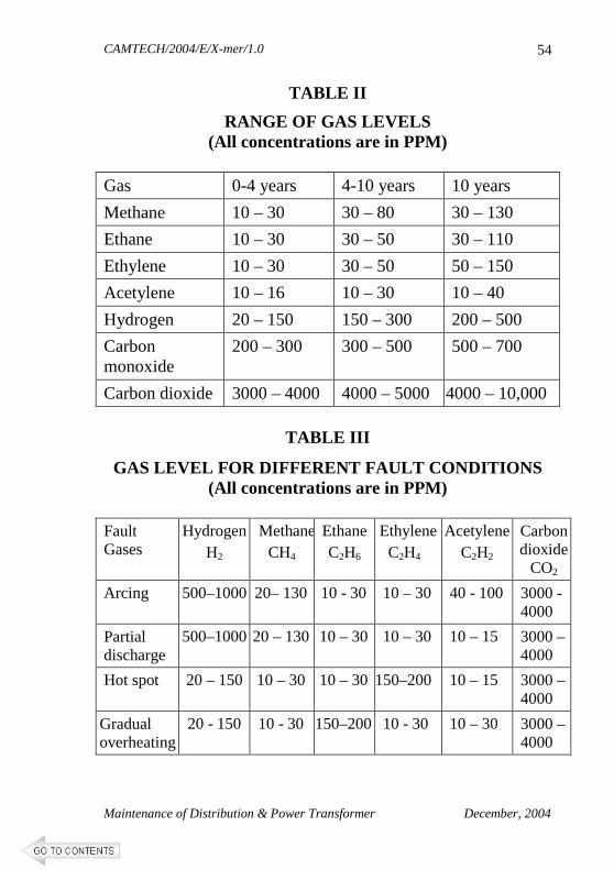
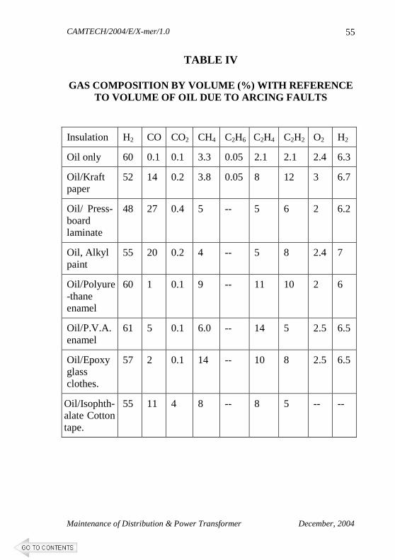
� The knowledge of solubility of Hydrocarbon and fixed gases at different temperature, in insulating oil helps in interpretation of gas analysis. The permissible concentration of dissolved gases in the oil of healthy transformer is shown in table II. The combinations of gas levels for different types of faults are shown in table III while table IV shows the gas composition by volume under arcing fault with participation of various components of solid dielectrics in a transformer.
CAMTECH/2004/E/X-mer/1.0
Maintenance of Distribution & Power Transformer December, 2004
52
� The absolute concentration of fault gases gives an indication of status of insulation of transformer, whereas the relative concentration of these gases provides a clue to the type of fault. For fault diagnosis the method based on Rogers analysis is adopted.
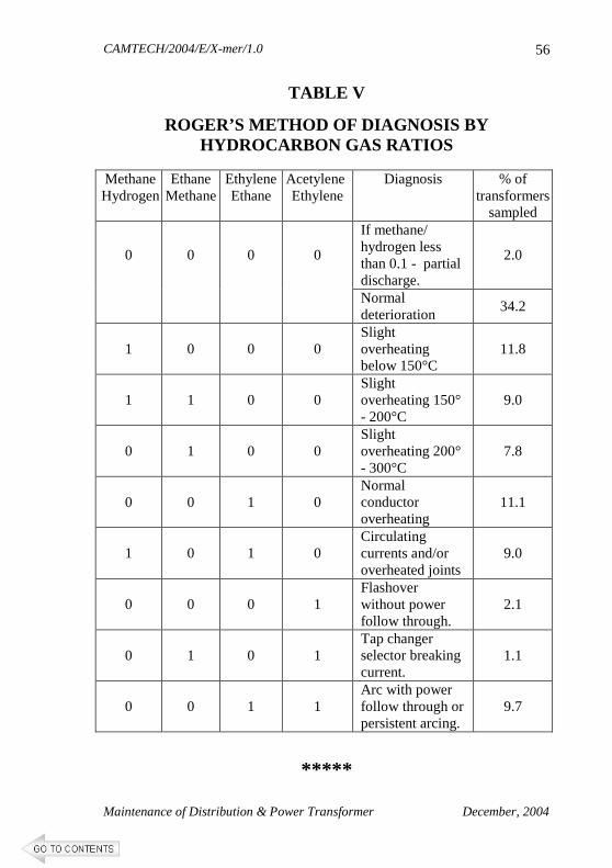
6.5.1 Roger’s Method
This method holds good for hydrocarbon gases. In this method the type of fault is detected by evaluating the gas ratios. Four ratios are used viz., Methane/Hydrogen, Ethane/Methane, Ethylene/Ethane and Acetylene/Ethylene. The value of ratios can be greater or smaller than unity. The ratio and type of fault represented by that ratio are given in table V.
6.6 DATA COLLECTION AND ANALYSIS
� The DGA should be performed regularly once a year on every transformer upto 4 years of service and thereafter twice a year upto 10 years and the frequency thereafter may be increased to thrice a year.
Note: Wherever the Buchholz relay operates, the dissolved gas analysis be carried out immediately after operation of the relay to ascertain the cause of fault.
� The results of the DGA for each transformer should be built into a data bank and based on the trend of the gas level over a period of time as well as the faults, if any, that the transformer had suffered, an analysis may be done to establish the exact nature of the incipient fault that may be developing in the transformer.
CAMTECH/2004/E/X-mer/1.0
Maintenance of Distribution & Power Transformer December, 2004
53
TABLE I
SOLUBILITY OF DIFFERENT GASES IN TRANSFORMER OIL AT 25°C, 1 ATM.
Gas Volume % with reference to volume of oil
Hydrogen 7
Oxygen 16
Nitrogen 8.6
Argon 15
Carbon Monoxide 9
Carbon Dioxide 120
Methane 30
Ethane 280
Ethylene 280
Acetylene 400
Propylene 400
Propane 1900
Butane 4000
CAMTECH/2004/E/X-mer/1.0
Maintenance of Distribution & Power Transformer December, 2004
54
TABLE II
RANGE OF GAS LEVELS (All concentrations are in PPM)
Gas 0-4 years 4-10 years 10 years
Methane 10 – 30 30 – 80 30 – 130
Ethane 10 – 30 30 – 50 30 – 110
Ethylene 10 – 30 30 – 50 50 – 150
Acetylene 10 – 16 10 – 30 10 – 40
Hydrogen 20 – 150 150 – 300 200 – 500
Carbon monoxide
200 – 300 300 – 500 500 – 700
Carbon dioxide 3000 – 4000 4000 – 5000 4000 – 10,000
TABLE III
GAS LEVEL FOR DIFFERENT FAULT CONDITIONS (All concentrations are in PPM)
Fault Gases
Hydrogen H2
MethaneCH4
Ethane C2H6
Ethylene C2H4
Acetylene C2H2
Carbon dioxide
CO2
Arcing 500–1000 20– 130 10 - 30 10 – 30 40 - 100 3000 - 4000
Partial discharge
500–1000 20 – 130 10 – 30 10 – 30 10 – 15 3000 – 4000
Hot spot 20 – 150 10 – 30 10 – 30 150–200 10 – 15 3000 – 4000
Gradual overheating
20 - 150 10 - 30 150–200 10 - 30 10 – 30 3000 – 4000
CAMTECH/2004/E/X-mer/1.0
Maintenance of Distribution & Power Transformer December, 2004
55
TABLE IV
GAS COMPOSITION BY VOLUME (%) WITH REFERENCE TO VOLUME OF OIL DUE TO ARCING FAULTS
Insulation H2 CO CO2 CH4 C2H6 C2H4 C2H2 O2 H2
Oil only 60 0.1 0.1 3.3 0.05 2.1 2.1 2.4 6.3
Oil/Kraft paper
52 14 0.2 3.8 0.05 8 12 3 6.7
Oil/ Press- board laminate
48 27 0.4 5 -- 5 6 2 6.2
Oil, Alkyl paint
55 20 0.2 4 -- 5 8 2.4 7
Oil/Polyure-thane enamel
60 1 0.1 9 -- 11 10 2 6
Oil/P.V.A. enamel
61 5 0.1 6.0 -- 14 5 2.5 6.5
Oil/Epoxy glass clothes.
57 2 0.1 14 -- 10 8 2.5 6.5
Oil/Isophth-alate Cotton tape.
55 11 4 8 -- 8 5 -- --
CAMTECH/2004/E/X-mer/1.0
Maintenance of Distribution & Power Transformer December, 2004
56
TABLE V
ROGER’S METHOD OF DIAGNOSIS BY HYDROCARBON GAS RATIOS
Methane Hydrogen
Ethane Methane
Ethylene Ethane
Acetylene Ethylene
Diagnosis % of transformers
sampled
0 0 0 0
If methane/ hydrogen less than 0.1 - partial discharge.
2.0
Normal deterioration
34.2
1 0 0 0 Slight overheating below 150°C
11.8
1 1 0 0 Slight overheating 150° - 200°C
9.0
0 1 0 0 Slight overheating 200° - 300°C
7.8
0 0 1 0 Normal conductor overheating
11.1
1 0 1 0 Circulating currents and/or overheated joints
9.0
0 0 0 1 Flashover without power follow through.
2.1
0 1 0 1 Tap changer selector breaking current.
1.1
0 0 1 1 Arc with power follow through or persistent arcing.
9.7
*****
CAMTECH/2004/E/X-mer/1.0
Maintenance of Distribution & Power Transformer December, 2004
57
CHAPTER 7
DO’S AND DON’TS 7.1 DO’S
1. Ensure all safety arrangements while working on electrical installation.
2. Ensure that all tool & tackles are in good working condition.
3. Check the protection system periodically.
4. Check silica gel regularly.
5. Check and thoroughly investigate the transformer whenever any alarm or protection system is operated.
6. Examine the bushings for dirt deposit, coats and clean them periodically.
7. Attend the bushing leakage immediately.
8. Do earthing of all points before starting maintenance work.
9. Keep all spares away from dirt.
10. Avoid un-balance loading on phases.
11. Clean conservator thoroughly before refilling.
12. Ensure proper functioning of Buchholz relay.
13. Ensure periodic testing of transformer oil.
CAMTECH/2004/E/X-mer/1.0
Maintenance of Distribution & Power Transformer December, 2004
58
7.2 DON’TS
1. Don’t use under capacity lifting jacks.
2. Don’t leave any loose connection.
3. Don’t meddle with protection system.
4. Don’t allow conservator oil level to fall below 1/4th level.
5. Don’t parallel transformer which do not full fill the necessary conditions.
6. Don’t allow unauthorised entry near the transformer.
7. Don’t overload the transformer than the specified limit.
8. Don’t over tight the nuts & bolts to stop any leakage.
9. Don’t overlook any unusual noise/ occurrence noticed in the substation.
10. Don’t use fuses higher than the prescribed ratings on HT and LT sides.
11. Don’t tamper with earthing connections.
12. Don’t keep the breather pipe open or exposed.
13. Don’t ignore safety rules during maintenance work.
14. Don’t re-energize the faulty transformer unless the Buchholz gas is analysed.
*****
CAMTECH/2004/E/X-mer/1.0
Maintenance of Distribution & Power Transformer December, 2004
59
REFERENCES
1. IS: 10028 (Pt.III) - 1981, reaffirmed 1993 & 1998 –Code of Practice for Selection, Installation and Maintenance of Transformers (Part– III Maintenance).
2. Manual of AC traction - Maintenance and operation - Volume II (part I) 1994.
3. Field study conducted at various Railway installations.
4. Presentations by various participants during seminar held at CAMTECH on dt. 17. 09. 2004.
CAMTECH/2004/E/X-mer/1.0
Maintenance of Distribution & Power Transformer December, 2004
60
If you have any suggestions and specific comments please write to us.
Contact person
Director Electrical
Postal address Indian Railways
Centre for Advanced Maintenance Technology, Maharajpur, Gwalior,
Pin Code - 474 020
Phone 0751 – 2470740 0751 – 2470803
Fax 0751 - 2470841
To upgrade maintenance technologies and methodologies and achieve improvement in productivity, performance of all Railway assets and manpower which inter-alia would cover reliability, availability, utilisation and efficiency.
OUR OBJECTIVE


![lalk/ku - vaga.study · lalk/u 3 bl izdkj osQ lalkèku vuohdj.kh; dgykrs gSaA dks;yk] isVªksfy;e rFkk izko`Qfrd xSl blosQ oqQN mnkgj.k gSaA izko`Qfrd lalkèkuksa dk forj.k HkwHkkx]](https://img.pdfslide.net/doc/110x75/5f0710fc7e708231d41b2273/lalkku-vagastudy-lalku-3-bl-izdkj-osq-lalkku-vuohdjkh-dgykrs-gsaa-dksyk.jpg)


![esllZ y{ehd`ik LVhy ,aM ikoj izk] fyfeVsM jk;ij¼N-x-½ e iLrkfor …enviscecb.org/270/Hindi.pdf · esllZ y{ehd`ik LVhy ,aM ikoj izk] fyfeVsM}kjk xke&lks.Mk] rglhy&,oa ftyk jk;ij¼N-x-½](https://img.pdfslide.net/doc/110x75/5e2dcfb8409f58715253fb95/esllz-yehdik-lvhy-am-ikoj-izk-fyfevsm-jkijn-x-e-ilrkfor-esllz-yehdik.jpg)


![esllZ y{ehd`ik LVhy ,aM ikoj izk] fyfeVsM jk;ij¼N-x-½ e ... · m|kx Hkh viuk jg gSA vf/kd mtk n{krk gkfly dju d fy, mPp ikoj buid {kerk d 12 Vu {kerk d nk bMD’ku Qu’k iw.kZ:i](https://img.pdfslide.net/doc/110x75/5f812ac92d596c646f66c933/esllz-yehdik-lvhy-am-ikoj-izk-fyfevsm-jkijn-x-e-mkx-hkh-viuk-jg-gsa.jpg)
![CITIZEN CHARTER ukxfjd vf/kdkj Ik= · 3-Land Acquisition, Development Works And Maintenance of Public Services 3-Hkw&vtZu] fodkl dk;ksZa ,oa tu&lsokvksa ds vuqj{k.k fo"k;d 4 -Redressal](https://img.pdfslide.net/doc/110x75/5f5d0a5aeb4d24482c5d305e/citizen-charter-ukxfjd-vfkdkj-ik-3-land-acquisition-development-works-and-maintenance.jpg)

![e-iz-iwoZ {k= fo|qr forj.k diuh fyfeVM]¼la0@l0½ lHkkx ... Folders/… · [Type text] Page 1 e-iz-iwoZ {k= fo|qr forj.k diuh fyfeVM]¼la0@l0½ lHkkx [ktqjkgks lwpuk dk vf/kdkj vf/kfu;e](https://img.pdfslide.net/doc/110x75/5f0dc7b47e708231d43c0c88/e-iz-iwoz-k-foqr-forjk-diuh-fyfevmla0l0-lhkkx-folders-type-text.jpg)


![ikoj Qkbul dkWikj'ku] 03 Qjojh] 2012 Ek;knd & nfo;k ,o ...pfcindia.com/hnsite/DocumentRepository/ckfinder/files/PFCTranscript_hi_03022012.pdf · - 4 -,d cBd Fkh vkj vf/kdkfjd :i l](https://img.pdfslide.net/doc/110x75/5d01005f88c99363028bd8e8/ikoj-qkbul-dkwikjku-03-qjojh-2012-ekknd-nfok-o-4-d-cbd-fkh-vkj.jpg)
![vkWVksesfVd flXufyax ij vuqj{k.k gLriqfLrdk · vius lq>ko gesa bl besay dirsntcamtech@gamil.com ij Hkstsa vFkok bl ij fy[k Hkstsa % mPp vuqj{k.k izks/kksfxdh dsUnz] gksVy vkfnR;kt](https://img.pdfslide.net/doc/110x75/5d2c7adc88c99363448b4e03/vkwvksesfvd-flxufyax-ij-vuqjkk-glriqflrdk-vius-lqko-gesa-bl-besay-dirsntcamtechgamilcom.jpg)


![Tkuin dkS”kkEch ds lokaZxh.k fodkl gsrq fotu MkD;wesUV fo|qr forj.k [k.M] dkS”kkEch](https://img.pdfslide.net/doc/110x75/5697bff01a28abf838cbadf8/tkuin-dkskkech-ds-lokazxhk-fodkl-gsrq-fotu-mkdwesuv-foqr-forjk-km.jpg)