Embed Size (px)
Citation preview
www.boschrexroth.com
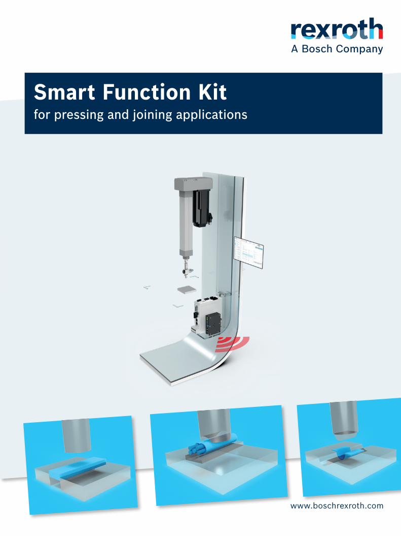
Smart Function Kitfor pressing and joining applications

2 Smart Function Kit |
Bosch Rexroth AG, R999002084/2021-06
Contents
Product description 4Hardware 5
Software 6
Technical data 8General 8
Hardware 8
Electromechanical Cylinder EMC 8IndraDyn S - servo motors MS2N 12Servo drive HCS01 14Safety zone module HSZ01 15Industrial PC PR21 16Force sensor 18Accessories 20
Software 21
General 21Dashboard 22Programming 22Process and Data 23Reference curve and Validation 23Interfaces 24
Selection and CAD Data 25
Order key 26
Supplementary documentation 27
| Smart Function Kit
3
Bosch Rexroth AG, R999002084/2021-06
Product description
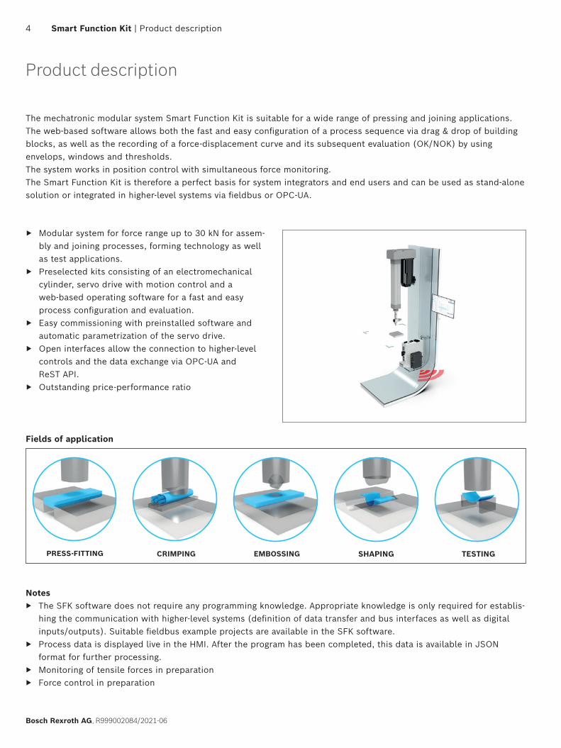
The mechatronic modular system Smart Function Kit is suitable for a wide range of pressing and joining applications.The web-based software allows both the fast and easy configuration of a process sequence via drag & drop of building blocks, as well as the recording of a force-displacement curve and its subsequent evaluation (OK/NOK) by using envelops, windows and thresholds.The system works in position control with simultaneous force monitoring.The Smart Function Kit is therefore a perfect basis for system integrators and end users and can be used as stand-alone solution or integrated in higher-level systems via fieldbus or OPC-UA.
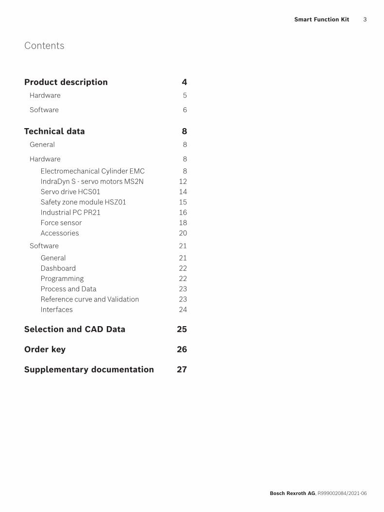
Fields of application
Notes ▶ The SFK software does not require any programming knowledge. Appropriate knowledge is only required for establis-
hing the communication with higher-level systems (definition of data transfer and bus interfaces as well as digital inputs/outputs). Suitable fieldbus example projects are available in the SFK software.
▶ Process data is displayed live in the HMI. After the program has been completed, this data is available in JSON format for further processing.
▶ Monitoring of tensile forces in preparation ▶ Force control in preparation
▶ Modular system for force range up to 30 kN for assem-bly and joining processes, forming technology as well as test applications.
▶ Preselected kits consisting of an electromechanical cylinder, servo drive with motion control and a web-based operating software for a fast and easy process configuration and evaluation.
▶ Easy commissioning with preinstalled software and automatic parametrization of the servo drive.
▶ Open interfaces allow the connection to higher-level controls and the data exchange via OPC-UA and ReST API.
▶ Outstanding price-performance ratio
4 Smart Function Kit | Product description
Bosch Rexroth AG, R999002084/2021-06
EMBOSSING SHAPING TESTINGCRIMPINGPRESS-FITTING
Hardware
Product description | Smart Function Kit Hardware
5
Bosch Rexroth AG, R999002084/2021-06
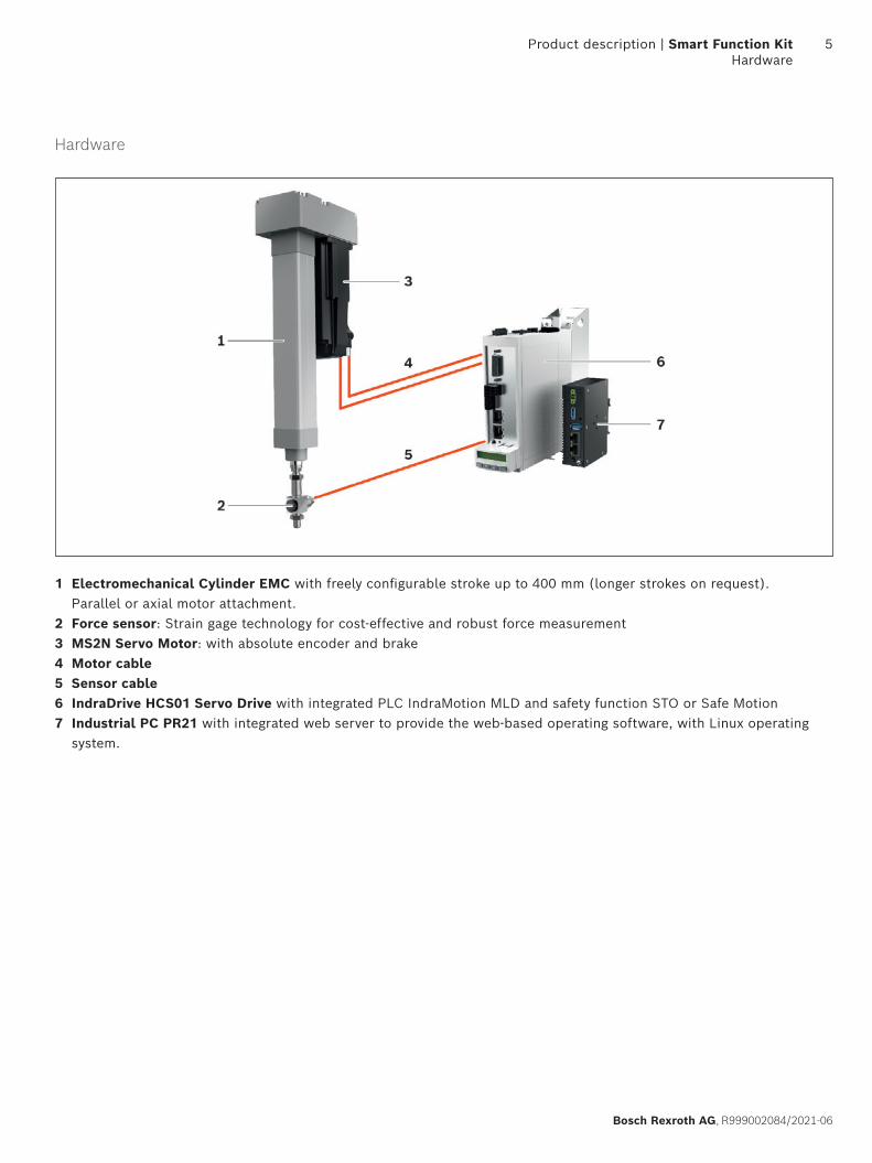
1 Electromechanical Cylinder EMC with freely configurable stroke up to 400 mm (longer strokes on request). Parallel or axial motor attachment.
2 Force sensor: Strain gage technology for cost-effective and robust force measurement 3 MS2N Servo Motor: with absolute encoder and brake 4 Motor cable5 Sensor cable6 IndraDrive HCS01 Servo Drive with integrated PLC IndraMotion MLD and safety function STO or Safe Motion 7 Industrial PC PR21 with integrated web server to provide the web-based operating software, with Linux operating
system.
Software
Thanks to the modern, intuitive web HMI with modular drag-and-drop process configuration, the software is ready for immediate use, with no previous knowledge required. The straightforward process for the graphical creation of all required evaluation and analysis elements is virtually self-explanatory.
Commissioning with auto configuration
▶ Preinstalled software ▶ Wizard for easy and fast commissioning ▶ Auto parameterization of the servo drive ▶ Support for commissioning with homing and jog mode
Simple programming and operation
▶ Modular process configuration with drag-and-drop ▶ Logic check of input data ▶ Optimization of the process supported by a control bar with live process values
▶ Simple graphical creation of evaluation and analysis elements ▶ Visualization of process and status information in the dashboard ▶ Fieldbus example projects for the easy integration in higher-level controls
Analysis and diagnosis via dashboard and log book
▶ Live display of the sequence and the force-displacement curves ▶ Visualization of the process result (OK/NOK) ▶ Storing of process data for quality assurance in internal database ▶ Process history with filter and export function (export in JSON format) ▶ Diagnostic functions: System parameters as well as status reports and statistics ▶ Log book with plain text error messages integrated in the software ▶ Data access via ReST programming interface
6 Smart Function Kit | Product description Software
Bosch Rexroth AG, R999002084/2021-06
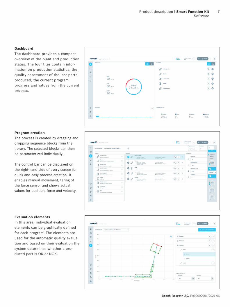
DashboardThe dashboard provides a compact overview of the plant and production status. The four tiles contain infor-mation on production statistics, the quality assessment of the last parts produced, the current program progress and values from the current process.
Program creationThe process is created by dragging and dropping sequence blocks from the library. The selected blocks can then be parameterized individually.
The control bar can be displayed on the right-hand side of every screen for quick and easy process creation. It enables manual movement, taring of the force sensor and shows actual values for position, force and velocity.
Evaluation elementsIn this area, individual evaluation elements can be graphically defined for each program. The elements are used for the automatic quality evalua-tion and based on their evaluation the system determines whether a pro-duced part is OK or NOK.
Product description | Smart Function Kit Software
7
Bosch Rexroth AG, R999002084/2021-06
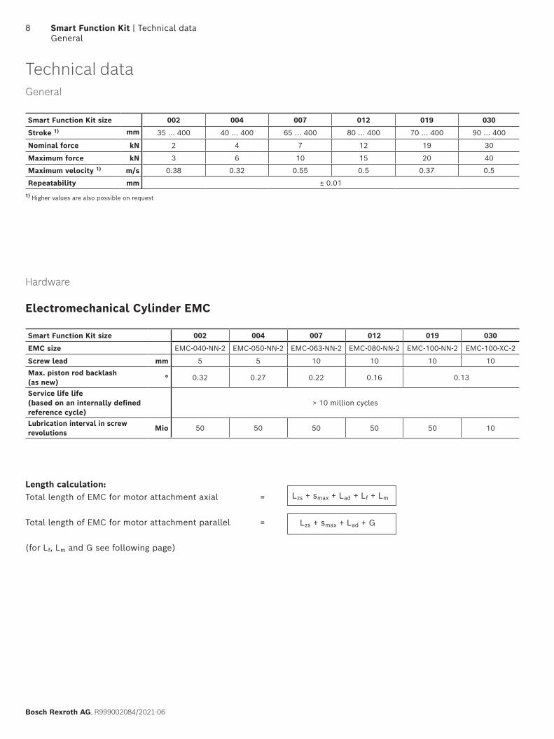
Lzs + smax + Lad + Lf + Lm
Lzs + smax + Lad + G
Electromechanical Cylinder EMC
Hardware
Smart Function Kit size 002 004 007 012 019 030
EMC size EMC-040-NN-2 EMC-050-NN-2 EMC-063-NN-2 EMC-080-NN-2 EMC-100-NN-2 EMC-100-XC-2
Screw lead mm 5 5 10 10 10 10
Max. piston rod backlash(as new)
° 0.32 0.27 0.22 0.16 0.13
Service life life(based on an internally defined reference cycle)
> 10 million cycles
Lubrication interval in screwrevolutions
Mio 50 50 50 50 50 10
General
Smart Function Kit size 002 004 007 012 019 030
Stroke 1) mm 35 ... 400 40 ... 400 65 ... 400 80 ... 400 70 ... 400 90 ... 400
Nominal force kN 2 4 7 12 19 30
Maximum force kN 3 6 10 15 20 40
Maximum velocity 1) m/s 0.38 0.32 0.55 0.5 0.37 0.5
Repeatability mm ± 0.01
1) Higher values are also possible on request
Length calculation: Total length of EMC for motor attachment axial =
Total length of EMC for motor attachment parallel =
(for Lf, Lm and G see following page)
Technical data
8 Smart Function Kit | Technical data General
Bosch Rexroth AG, R999002084/2021-06
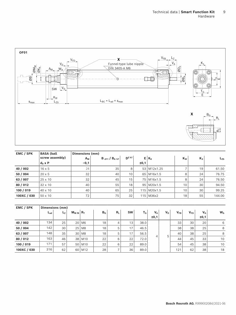
X
X
VG
KW
smax
WA
LBC = Lad + smax
ØB
A
ØD
Z
LZVFB
VA
TG
T G
E
E
Kx
VFD
AM
VD
ØM
M
ØK K
SW
ØB
BGRL
R T
LZS
OF01
Funnel-type lube nippleDIN 3405-A M6
EMC / SPK BASA (ballscrew assembly)
Dimensions (mm)AM B d11 / BA h7 DZ h7 E KK KW KX LZS
d0 x P –0,1 ±0,1
40 / 002 16 x 5 24 35 8 53 M12x1.25 7 19 61.50
50 / 004 20 x 5 32 40 10 65 M16x1.5 8 24 76.75
63 / 007 25 x 10 32 45 15 75 M16x1.5 8 24 76.50
80 / 012 32 x 10 40 55 18 95 M20x1.5 10 30 94.50
100 / 019 40 x 10 40 65 25 115 M20x1.5 10 30 99.25
100XC / 030 50 x 10 72 75 32 115 M36x2 18 55 144.00
EMC / SPK Dimensions (mm)Lad LZ MM f8 RT BG RL SW TG VA VD VFB VFD VG WA
±0,1 ±0,1
40 / 002 134 25 20 M6 18 4 13 38.0
4 5
33 30 20 6
50 / 004 142 30 25 M8 18 5 17 46.5 38 38 25 8
63 / 007 148 35 30 M8 18 5 17 56.5 40 38 25 8
80 / 012 163 46 38 M10 22 6 22 72.0 44 45 33 10
100 / 019 171 57 50 M10 22 6 22 89.0 54 45 38 10
100XC / 030 316 62 60 M12 28 7 36 89.0 121 62 38 18
Technical data | Smart Function Kit Hardware
9
Bosch Rexroth AG, R999002084/2021-06
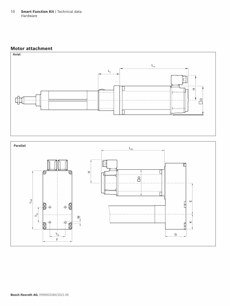
Lm
Lf
D
H
Axial
G
KE
H
D
Lm
M
F
TG
T G
L sd
Parallel
Motor attachment
10 Smart Function Kit | Technical data Hardware
Bosch Rexroth AG, R999002084/2021-06
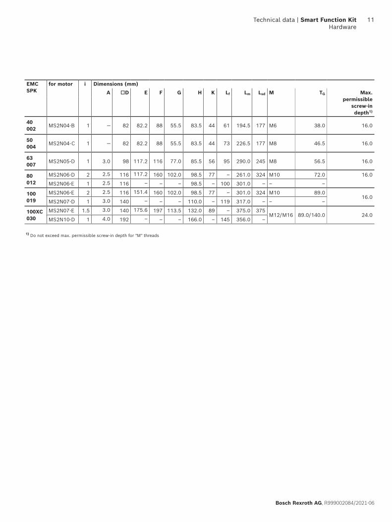
1) Do not exceed max. permissible screw-in depth for "M" threads
EMCSPK
for motor i Dimensions (mm)
A D E F G H K Lf Lm Lsd M TG Max.permissible
screw-indepth1)
40002
MS2N04-B 1 — 82 82.2 88 55.5 83.5 44 61 194.5 177 M6 38.0 16.0
50004
MS2N04-C 1 — 82 82.2 88 55.5 83.5 44 73 226.5 177 M8 46.5 16.0
63007
MS2N05-D 1 3.0 98 117.2 116 77.0 85.5 56 95 290.0 245 M8 56.5 16.0
80012
MS2N06-D 2 2.5 116 117.2 160 102.0 98.5 77 – 261.0 324 M10 72.0 16.0
MS2N06-E 1 2.5 116 – – – 98.5 – 100 301.0 – – –
100019
MS2N06-E 2 2.5 116 151.4 160 102.0 98.5 77 – 301.0 324 M10 89.016.0
MS2N07-D 1 3.0 140 – – – 110.0 – 119 317.0 – – –
100XC030
MS2N07-E 1.5 3.0 140 175.6 197 113.5 132.0 89 – 375.0 375M12/M16 89.0/140.0 24.0
MS2N10-D 1 4.0 192 – – – 166.0 – 145 356.0 –
Technical data | Smart Function Kit Hardware
11
Bosch Rexroth AG, R999002084/2021-06
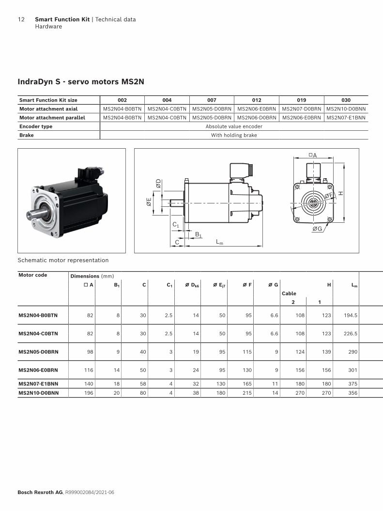
IndraDyn S - servo motors MS2N
A
⌀G
⌀F H
B1
C1
C
⌀E
⌀D
Lm
Schematic motor representation
Motor code Dimensions (mm) Motordata
Mot
or
conn
ecti
on
Bra
ke
Type code
A B1 C C1 ⌀ Dk6 ⌀ Ej7 ⌀ F ⌀ G H Lm nmax M0 Mmax Mbr Jm Jbr mm mbr
Cable (min–1) (Nm) (Nm) (Nm) (kgm2) (kgm2) (kg) (kg)
2 1
MS2N04-B0BTN 82 8 30 2.5 14 50 95 6.6 108 123 194.5 6 000 1.75 5.9 5.0 0.00007 0.000040 2.7 0.72 Y MS2N04-B0BTN-BMDH1-NNNNE-NN
1 Y MS2N04-B0BTN-CMSH1-NNNNE-NN
MS2N04-C0BTN 82 8 30 2.5 14 50 95 6.6 108 123 226.5 6 000 2.80 12.0 5.0 0.00011 0.000050 3.7 0.72 Y MS2N04-C0BTN-BMDH1-NNNNE-NN
1 Y MS2N04-C0BTN-CMSH1-NNNNE-NN
MS2N05-D0BRN 98 9 40 3 19 95 115 9 124 139 290 6 000 7.90 31.3 10.0 0.00040 0.000110 7.3 1.12 Y MS2N05-D0BRN-BMDH1-NNNNE-NN
1 Y MS2N05-D0BRN-CMSH1-NNNNE-NN
MS2N06-E0BRN 116 14 50 3 24 95 130 9 156 156 301 6 000 13.0 49.0 15.0 0.00089 0.000140 11.5 1.52 Y MS2N06-E0BRN-BMUH2-NNNNE-NN
1 Y MS2N06-E0BRN-CMSH2-NNNNE-NN
MS2N07-E1BNN 140 18 58 4 32 130 165 11 180 180 375 6 000 25.8 128.5 36.0 0.00752 0.000041 23.0 3.0 2 Y MS2N07-E1BNN-BMVH2-NNNNE-NN
MS2N10-D0BNN 196 20 80 4 38 180 215 14 270 270 356 6 000 51.0 142.0 53.0 0.00810 0.001470 34.0 5.0 2 Y MS2N10-D0BNN-BMVH2-NNNNE-NN
Smart Function Kit size 002 004 007 012 019 030
Motor attachment axial MS2N04-B0BTN MS2N04-C0BTN MS2N05-D0BRN MS2N06-E0BRN MS2N07-D0BRN MS2N10-D0BNN
Motor attachment parallel MS2N04-B0BTN MS2N04-C0BTN MS2N05-D0BRN MS2N06-D0BRN MS2N06-E0BRN MS2N07-E1BNN
Encoder type Absolute value encoder
Brake With holding brake
12 Smart Function Kit | Technical data Hardware
Bosch Rexroth AG, R999002084/2021-06
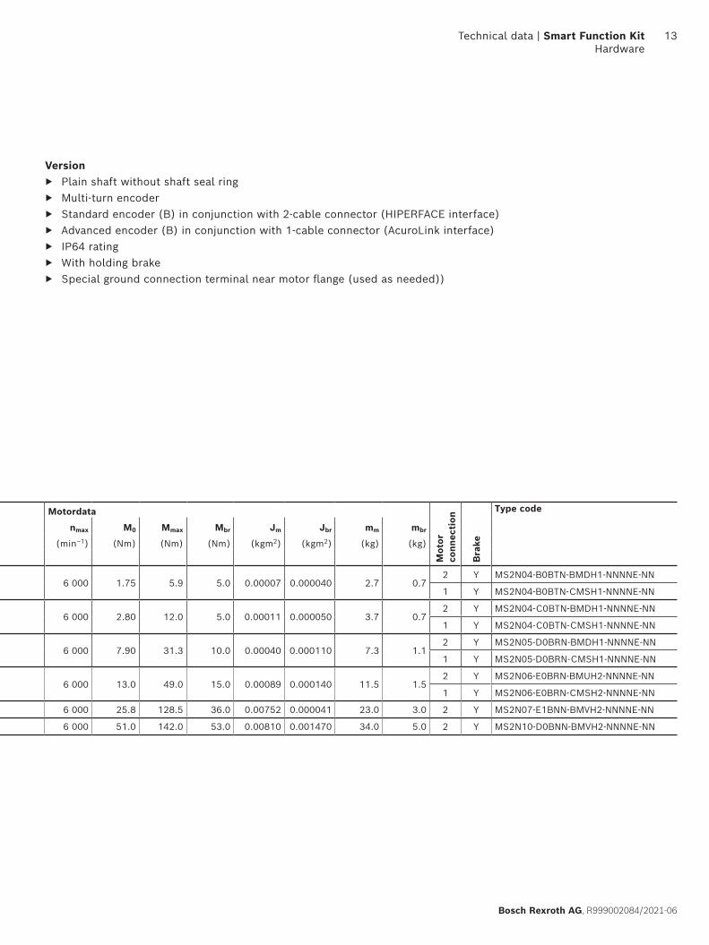
Version ▶ Plain shaft without shaft seal ring ▶ Multi-turn encoder ▶ Standard encoder (B) in conjunction with 2-cable connector (HIPERFACE interface) ▶ Advanced encoder (B) in conjunction with 1-cable connector (AcuroLink interface) ▶ IP64 rating ▶ With holding brake ▶ Special ground connection terminal near motor flange (used as needed))
Motor code Dimensions (mm) Motordata
Mot
or
conn
ecti
on
Bra
ke
Type code
A B1 C C1 ⌀ Dk6 ⌀ Ej7 ⌀ F ⌀ G H Lm nmax M0 Mmax Mbr Jm Jbr mm mbr
Cable (min–1) (Nm) (Nm) (Nm) (kgm2) (kgm2) (kg) (kg)
2 1
MS2N04-B0BTN 82 8 30 2.5 14 50 95 6.6 108 123 194.5 6 000 1.75 5.9 5.0 0.00007 0.000040 2.7 0.72 Y MS2N04-B0BTN-BMDH1-NNNNE-NN
1 Y MS2N04-B0BTN-CMSH1-NNNNE-NN
MS2N04-C0BTN 82 8 30 2.5 14 50 95 6.6 108 123 226.5 6 000 2.80 12.0 5.0 0.00011 0.000050 3.7 0.72 Y MS2N04-C0BTN-BMDH1-NNNNE-NN
1 Y MS2N04-C0BTN-CMSH1-NNNNE-NN
MS2N05-D0BRN 98 9 40 3 19 95 115 9 124 139 290 6 000 7.90 31.3 10.0 0.00040 0.000110 7.3 1.12 Y MS2N05-D0BRN-BMDH1-NNNNE-NN
1 Y MS2N05-D0BRN-CMSH1-NNNNE-NN
MS2N06-E0BRN 116 14 50 3 24 95 130 9 156 156 301 6 000 13.0 49.0 15.0 0.00089 0.000140 11.5 1.52 Y MS2N06-E0BRN-BMUH2-NNNNE-NN
1 Y MS2N06-E0BRN-CMSH2-NNNNE-NN
MS2N07-E1BNN 140 18 58 4 32 130 165 11 180 180 375 6 000 25.8 128.5 36.0 0.00752 0.000041 23.0 3.0 2 Y MS2N07-E1BNN-BMVH2-NNNNE-NN
MS2N10-D0BNN 196 20 80 4 38 180 215 14 270 270 356 6 000 51.0 142.0 53.0 0.00810 0.001470 34.0 5.0 2 Y MS2N10-D0BNN-BMVH2-NNNNE-NN
Technical data | Smart Function Kit Hardware
13
Bosch Rexroth AG, R999002084/2021-06
AC1
C2
B2
B1
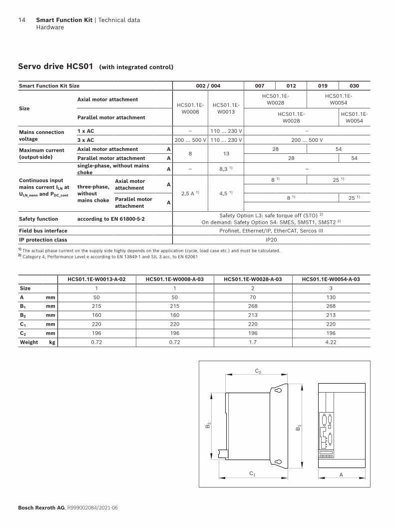
Servo drive HCS01
Smart Function Kit Size 002 / 004 007 012 019 030
Size
Axial motor attachmentHCS01.1E-
W0008HCS01.1E-
W0013
HCS01.1E-W0028
HCS01.1E-W0054
Parallel motor attachmentHCS01.1E-
W0028HCS01.1E-
W0054
Mains connectionvoltage
1 x AC ‒ 110 ... 230 V ‒
3 x AC 200 ... 500 V 110 ... 230 V 200 ... 500 V
Maximum current(output-side)
Axial motor attachment A8 13
28 54
Parallel motor attachment A 28 54
Continuous inputmains current ILN at ULN_nenn and PDC_cont
single-phase, without mains choke
A ‒ 8,3 1) ‒
three-phase,withoutmains choke
Axial motor attachment
A
2,5 A 1) 4,5 1)
8 1) 25 1)
Parallel motor attachment
A8 1) 25 1)
Safety function according to EN 61800-5-2Safety Option L3: safe torque off (STO) 2)
On demand: Safety Option S4: SMES, SMST1, SMST2 2)
Field bus interface Profinet, Ethernet/IP, EtherCAT, Sercos III
IP protection class IP20
1) The actual phase current on the supply side highly depends on the application (cycle, load case etc.) and must be calculated.2) Category 4, Performance Level e according to EN 13849-1 and SIL 3 acc. to EN 62061
HCS01.1E-W0013-A-02 HCS01.1E-W0008-A-03 HCS01.1E-W0028-A-03 HCS01.1E-W0054-A-03
Size 1 1 2 3
A mm 50 50 70 130
B1 mm 215 215 268 268
B2 mm 160 160 213 213
C1 mm 220 220 220 220
C2 mm 196 196 196 196
Weight kg 0.72 0.72 1.7 4.22
(with integrated control)
14 Smart Function Kit | Technical data Hardware
Bosch Rexroth AG, R999002084/2021-06
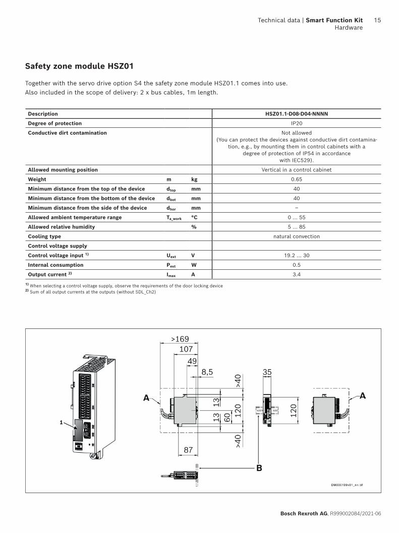
Safety zone module HSZ01
Together with the servo drive option S4 the safety zone module HSZ01.1 comes into use.Also included in the scope of delivery: 2 x bus cables, 1m length.
Description HSZ01.1-D08-D04-NNNN
Degree of protection IP20
Conductive dirt contamination Not allowed(You can protect the devices against conductive dirt contamina-
tion, e.g., by mounting them in control cabinets with adegree of protection of IP54 in accordance
with IEC529).
Allowed mounting position Vertical in a control cabinet
Weight m kg 0.65
Minimum distance from the top of the device dtop mm 40
Minimum distance from the bottom of the device dbot mm 40
Minimum distance from the side of the device dhor mm –
Allowed ambient temperature range Ta_work °C 0 ... 55
Allowed relative humidity % 5 ... 85
Cooling type natural convection
Control voltage supply
Control voltage input 1) Uext V 19.2 ... 30
Internal consumption Pext W 0.5
Output current 2) Imax A 3.4
1) When selecting a control voltage supply, observe the requirements of the door locking device2) Sum of all output currents at the outputs (without SDL_Ch2)
Technical data | Smart Function Kit Hardware
15
Bosch Rexroth AG, R999002084/2021-06
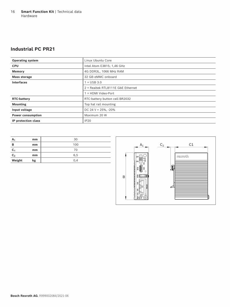
A1 C1C2
B
A1 mm 30
B mm 100
C1 mm 70
C2 mm 6,5
Weight kg 0,4
Industrial PC PR21
Operating system Linux Ubuntu Core
CPU Intel Atom E3815; 1,46 GHz
Memory 4G DDR3L, 1066 MHz RAM
Mass storage 32 GB eMMC onboard
Interfaces 1 × USB 3.0
2 × Realtek RTL8111E GbE Ethernet
1 × HDMI Video-Port
RTC-battery RTC-battery button cell BR2032
Mounting Top hat rail mounting
Input voltage DC 24 V + 25%, -20%
Power consumption Maximum 20 W
IP protection class IP20
16 Smart Function Kit | Technical data Hardware
Bosch Rexroth AG, R999002084/2021-06

Technical data | Smart Function Kit Hardware
17
Bosch Rexroth AG, R999002084/2021-06
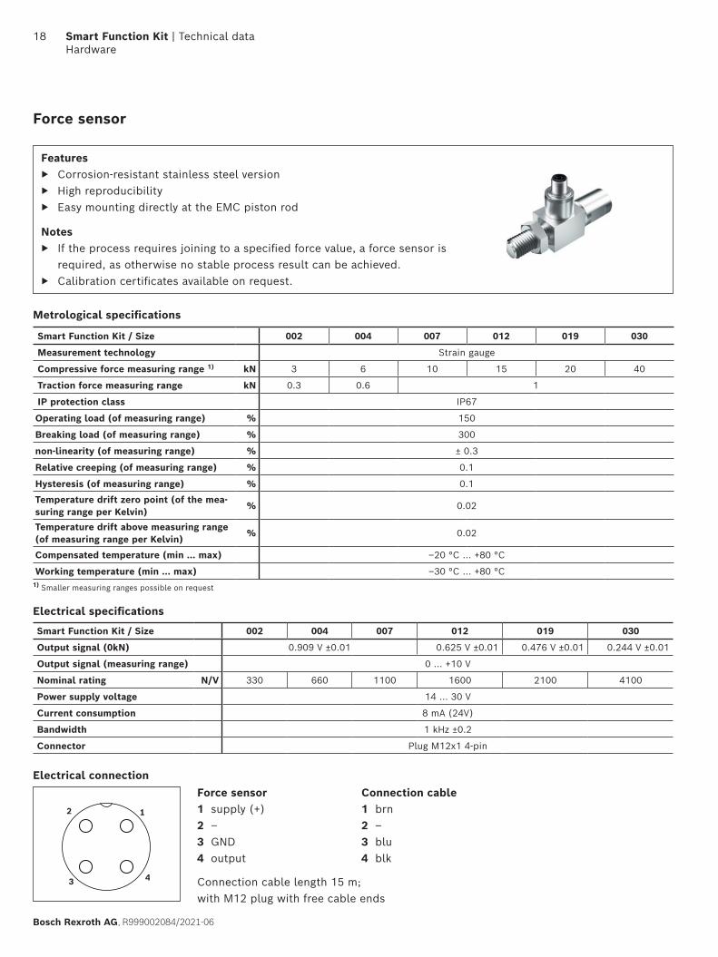
Metrological specifications
Features ▶ Corrosion-resistant stainless steel version
▶ High reproducibility ▶ Easy mounting directly at the EMC piston rod
Notes ▶ If the process requires joining to a specified force value, a force sensor is
required, as otherwise no stable process result can be achieved. ▶ Calibration certificates available on request.
Force sensor
1) Smaller measuring ranges possible on request
Smart Function Kit / Size 002 004 007 012 019 030
Measurement technology Strain gauge
Compressive force measuring range 1) kN 3 6 10 15 20 40
Traction force measuring range kN 0.3 0.6 1
IP protection class IP67
Operating load (of measuring range) % 150
Breaking load (of measuring range) % 300
non-linearity (of measuring range) % ± 0.3
Relative creeping (of measuring range) % 0.1
Hysteresis (of measuring range) % 0.1
Temperature drift zero point (of the mea-suring range per Kelvin)
% 0.02
Temperature drift above measuring range(of measuring range per Kelvin)
% 0.02
Compensated temperature (min ... max) –20 °C ... +80 °C
Working temperature (min ... max) –30 °C ... +80 °C
12
43
Electrical specifications
Smart Function Kit / Size 002 004 007 012 019 030
Output signal (0kN) 0.909 V ±0.01 0.625 V ±0.01 0.476 V ±0.01 0.244 V ±0.01
Output signal (measuring range) 0 ... +10 V
Nominal rating N/V 330 660 1100 1600 2100 4100
Power supply voltage 14 ... 30 V
Current consumption 8 mA (24V)
Bandwidth 1 kHz ±0.2
Connector Plug M12x1 4-pin
Connection cable length 15 m;with M12 plug with free cable ends
Electrical connectionForce sensor1 supply (+)2 –3 GND4 output
Connection cable1 brn 2 –3 blu4 blk
18 Smart Function Kit | Technical data Hardware
Bosch Rexroth AG, R999002084/2021-06
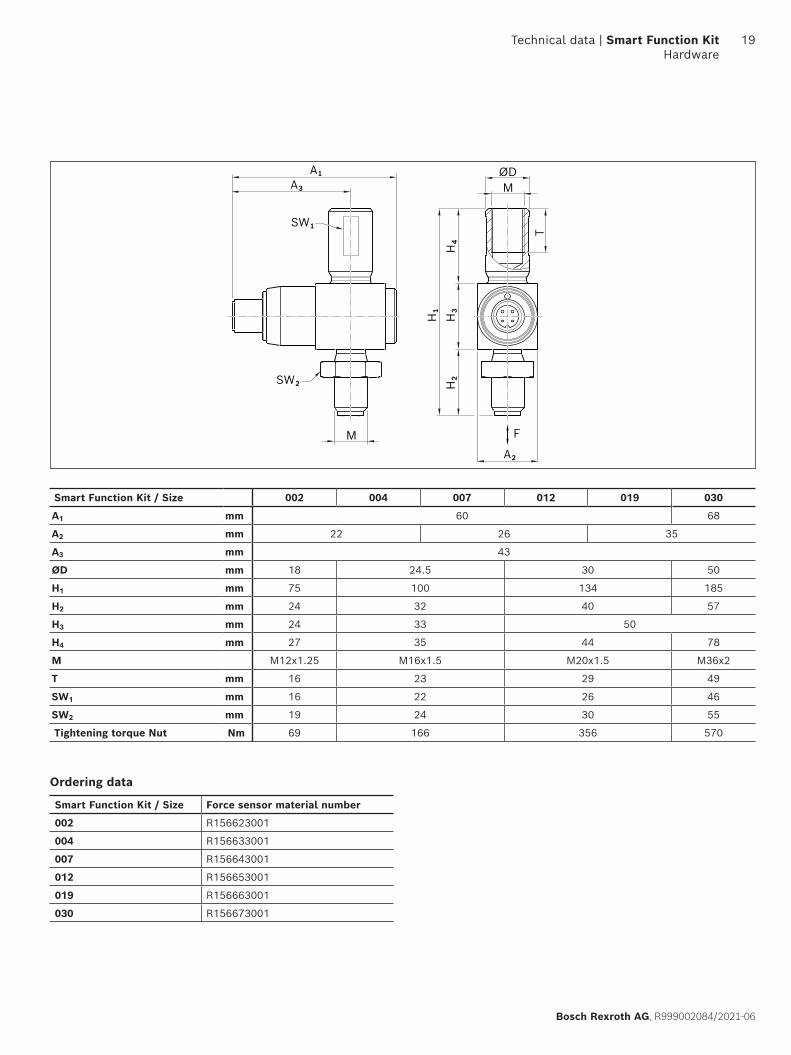
F
SW₁
SW₂
A₂H
₂
A₃A₁
H₄
H₁
M
M
T
H₃
ØD
Smart Function Kit / Size Force sensor material number
002 R156623001
004 R156633001
007 R156643001
012 R156653001
019 R156663001
030 R156673001
Ordering data
Smart Function Kit / Size 002 004 007 012 019 030
A1 mm 60 68
A2 mm 22 26 35
A3 mm 43
ØD mm 18 24.5 30 50
H1 mm 75 100 134 185
H2 mm 24 32 40 57
H3 mm 24 33 50
H4 mm 27 35 44 78
M M12x1.25 M16x1.5 M20x1.5 M36x2
T mm 16 23 29 49
SW1 mm 16 22 26 46
SW2 mm 19 24 30 55
Tightening torque Nut Nm 69 166 356 570
Technical data | Smart Function Kit Hardware
19
Bosch Rexroth AG, R999002084/2021-06
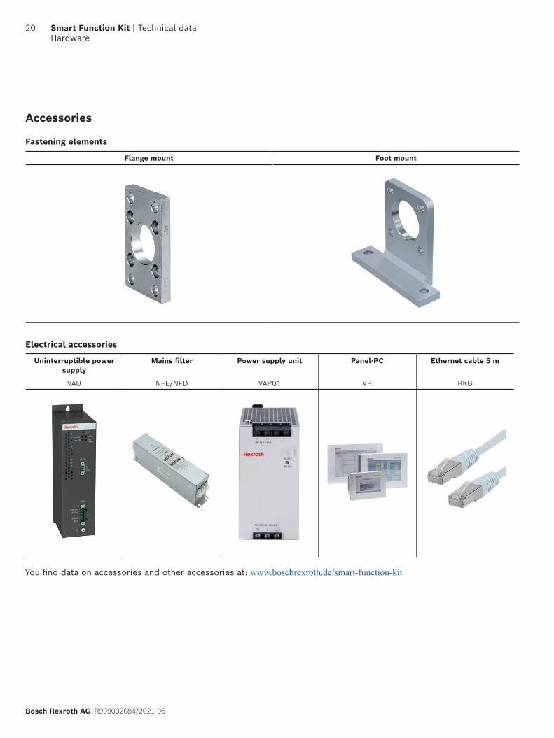
Accessories
Fastening elements
Electrical accessories
Flange mount Foot mount
Uninterruptible power supply
Mains filter Power supply unit Panel-PC Ethernet cable 5 m
VAU NFE/NFD VAP01 VR RKB
You find data on accessories and other accessories at: www.boschrexroth.de/smart-function-kit
20 Smart Function Kit | Technical data Hardware
Bosch Rexroth AG, R999002084/2021-06
General
Software
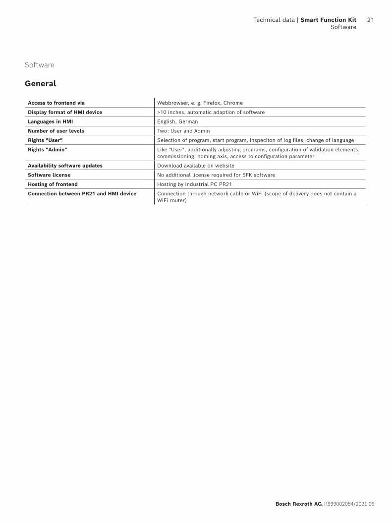
Access to frontend via Webbrowser, e. g. Firefox, Chrome
Display format of HMI device >10 inches, automatic adaption of software
Languages in HMI English, German
Number of user levels Two: User and Admin
Rights "User" Selection of program, start program, inspeciton of log files, change of language
Rights "Admin" Like "User", additionally adjusting programs, configuration of validation elements, commissioning, homing axis, access to configuration parameter
Availability software updates Download available on website
Software license No additional license required for SFK software
Hosting of frontend Hosting by Industrial PC PR21
Connection between PR21 and HMI device Connection through network cable or WiFi (scope of delivery does not contain a WiFi router)
Technical data | Smart Function Kit Software
21
Bosch Rexroth AG, R999002084/2021-06
Dashboard
Programming
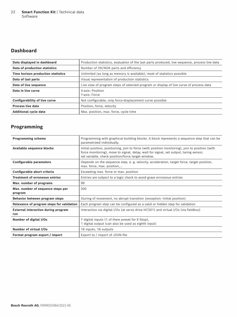
Data displayed in dashboard Production statistics, evaluation of the last parts produced, live sequence, process live data
Data of production statistics Number of OK/NOK parts and efficiency
Time horizon production statistics Unlimited (as long as memory is available), reset of statistics possible
Data of last parts Visual representation of production statistics
Data of live sequence Live view of program steps of selected program or display of live curve of process data
Data in live curve X-axis: Position Y-axis: Force
Configurability of live curve Not configurable, only force-displacement curve possible
Process live data Position, force, velocity
Additional cycle data Max. position, max. force, cycle time
Programming scheme Programming with graphical building blocks. A block represents a sequence step that can be parametrized individually.
Available sequence blocks Initial position, positioning, join to force (with position monitoring), join to position (with force monitoring), move to signal, delay, wait for signal, set output, taring sensor, set variable, check position/force target window.
Configurable parameters Depends on the sequence step, e. g. velocity, acceleration, target force, target position, max. force, max. position,…
Configurable abort criteria Exceeding max. force or max. position
Treatment of erroneous entries Entries are subject to a logic check to avoid grave erroneous entries
Max. number of programs 99
Max. number of sequence steps per program
500
Behavior between program steps Sluring of movement, no abrupt transition (exception: Initial position)
Relevance of program steps for validation Each program step can be configured as a valid or hidden step for validation
External interaction during program run
Interaction via digital I/Os (at servo drive HCS01) and virtual I/Os (via fieldbus)
Number of digital I/Os 7 digital inputs (1 of them preset for E-Stop),1 digital output (can also be used as eighth input)
Number of virtual I/Os 16 inputs, 16 outputs
Format program export / import Export to / import of JSON file
22 Smart Function Kit | Technical data Software
Bosch Rexroth AG, R999002084/2021-06
Reference curve and Validation
Process and Data
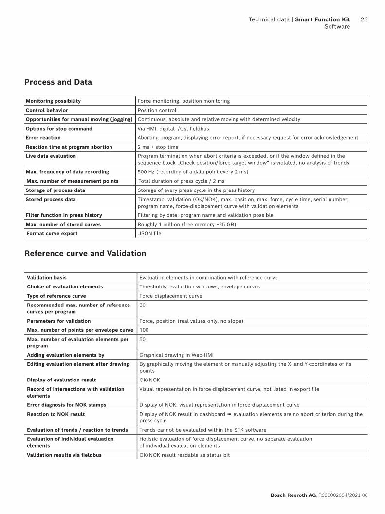
Monitoring possibility Force monitoring, position monitoring
Control behavior Position control
Opportunities for manual moving (jogging) Continuous, absolute and relative moving with determined velocity
Options for stop command Via HMI, digital I/Os, fieldbus
Error reaction Aborting program, displaying error report, if necessary request for error acknowledgement
Reaction time at program abortion 2 ms + stop time
Live data evaluation Program termination when abort criteria is exceeded, or if the window defined in the sequence block „Check position/force target window“ is violated, no analysis of trends
Max. frequency of data recording 500 Hz (recording of a data point every 2 ms)
Max. number of measurement points Total duration of press cycle / 2 ms
Storage of process data Storage of every press cycle in the press history
Stored process data Timestamp, validation (OK/NOK), max. position, max. force, cycle time, serial number, program name, force-displacement curve with validation elements
Filter function in press history Filtering by date, program name and validation possible
Max. number of stored curves Roughly 1 million (free memory ~25 GB)
Format curve export JSON file
Validation basis Evaluation elements in combination with reference curve
Choice of evaluation elements Thresholds, evaluation windows, envelope curves
Type of reference curve Force-displacement curve
Recommended max. number of reference curves per program
30
Parameters for validation Force, position (real values only, no slope)
Max. number of points per envelope curve 100
Max. number of evaluation elements per program
50
Adding evaluation elements by Graphical drawing in Web-HMI
Editing evaluation element after drawing By graphically moving the element or manually adjusting the X- and Y-coordinates of its points
Display of evaluation result OK/NOK
Record of intersections with validation elements
Visual representation in force-displacement curve, not listed in export file
Error diagnosis for NOK stamps Display of NOK, visual representation in force-displacement curve
Reaction to NOK result Display of NOK result in dashboard ! evaluation elements are no abort criterion during the press cycle
Evaluation of trends / reaction to trends Trends cannot be evaluated within the SFK software
Evaluation of individual evaluation elements
Holistic evaluation of force-displacement curve, no separate evaluation of individual evaluation elements
Validation results via fieldbus OK/NOK result readable as status bit
Technical data | Smart Function Kit Software
23
Bosch Rexroth AG, R999002084/2021-06
Interfaces
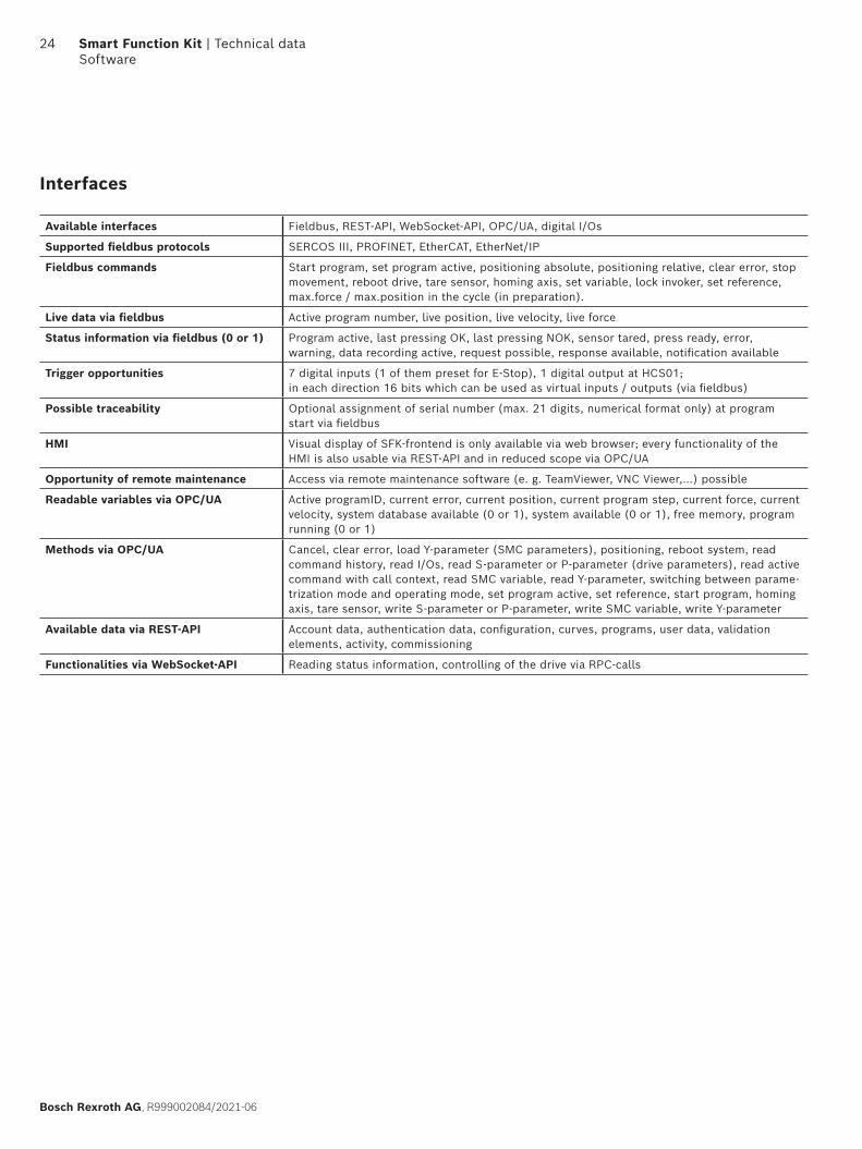
Available interfaces Fieldbus, REST-API, WebSocket-API, OPC/UA, digital I/Os
Supported fieldbus protocols SERCOS III, PROFINET, EtherCAT, EtherNet/IP
Fieldbus commands Start program, set program active, positioning absolute, positioning relative, clear error, stop movement, reboot drive, tare sensor, homing axis, set variable, lock invoker, set reference, max.force / max.position in the cycle (in preparation).
Live data via fieldbus Active program number, live position, live velocity, live force
Status information via fieldbus (0 or 1) Program active, last pressing OK, last pressing NOK, sensor tared, press ready, error, warning, data recording active, request possible, response available, notification available
Trigger opportunities 7 digital inputs (1 of them preset for E-Stop), 1 digital output at HCS01; in each direction 16 bits which can be used as virtual inputs / outputs (via fieldbus)
Possible traceability Optional assignment of serial number (max. 21 digits, numerical format only) at program start via fieldbus
HMI Visual display of SFK-frontend is only available via web browser; every functionality of the HMI is also usable via REST-API and in reduced scope via OPC/UA
Opportunity of remote maintenance Access via remote maintenance software (e. g. TeamViewer, VNC Viewer,…) possible
Readable variables via OPC/UA Active programID, current error, current position, current program step, current force, current velocity, system database available (0 or 1), system available (0 or 1), free memory, program running (0 or 1)
Methods via OPC/UA Cancel, clear error, load Y-parameter (SMC parameters), positioning, reboot system, read command history, read I/Os, read S-parameter or P-parameter (drive parameters), read active command with call context, read SMC variable, read Y-parameter, switching between parame-trization mode and operating mode, set program active, set reference, start program, homing axis, tare sensor, write S-parameter or P-parameter, write SMC variable, write Y-parameter
Available data via REST-API Account data, authentication data, configuration, curves, programs, user data, validation elements, activity, commissioning
Functionalities via WebSocket-API Reading status information, controlling of the drive via RPC-calls
24 Smart Function Kit | Technical data Software
Bosch Rexroth AG, R999002084/2021-06
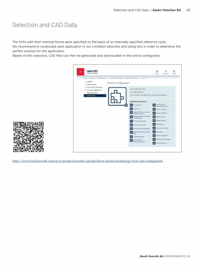
Selection and CAD Data
The SFKs with their nominal forces were specified on the basis of an internally specified reference cycle. We recommend to recalculate each application in our LinSelect selection and sizing tool in order to determine the perfect solution for the application.Based on this selection, CAD files can then be generated and downloaded in the online configurator.
https://www.boschrexroth.com/en/xc/products/product-groups/linear-motion-technology/tools-and-configurators
25 Selection and CAD Data | Smart Function Kit
Bosch Rexroth AG, R999002084/2021-06
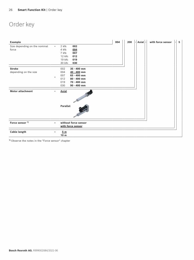
Example 004 200 - Axial - with force sensor - 5
Size depending on the nominal force
= 2 kN: 0024 kN: 0047 kN: 00712 kN: 01219 kN: 01930 kN: 030
Strokedepending on the size
=
002 35 - 400 mm004 40 - 400 mm007 65 - 400 mm012 80 - 400 mm019 70 - 400 mm030 90 - 400 mm
Motor attachment = Axial
Parallel
Force sensor 1) = without force sensorwith force sensor
Cable length = 5 m 10 m
1) Observe the notes in the "Force sensor" chapter
26 Smart Function Kit | Order key
Bosch Rexroth AG, R999002084/2021-06
Order key
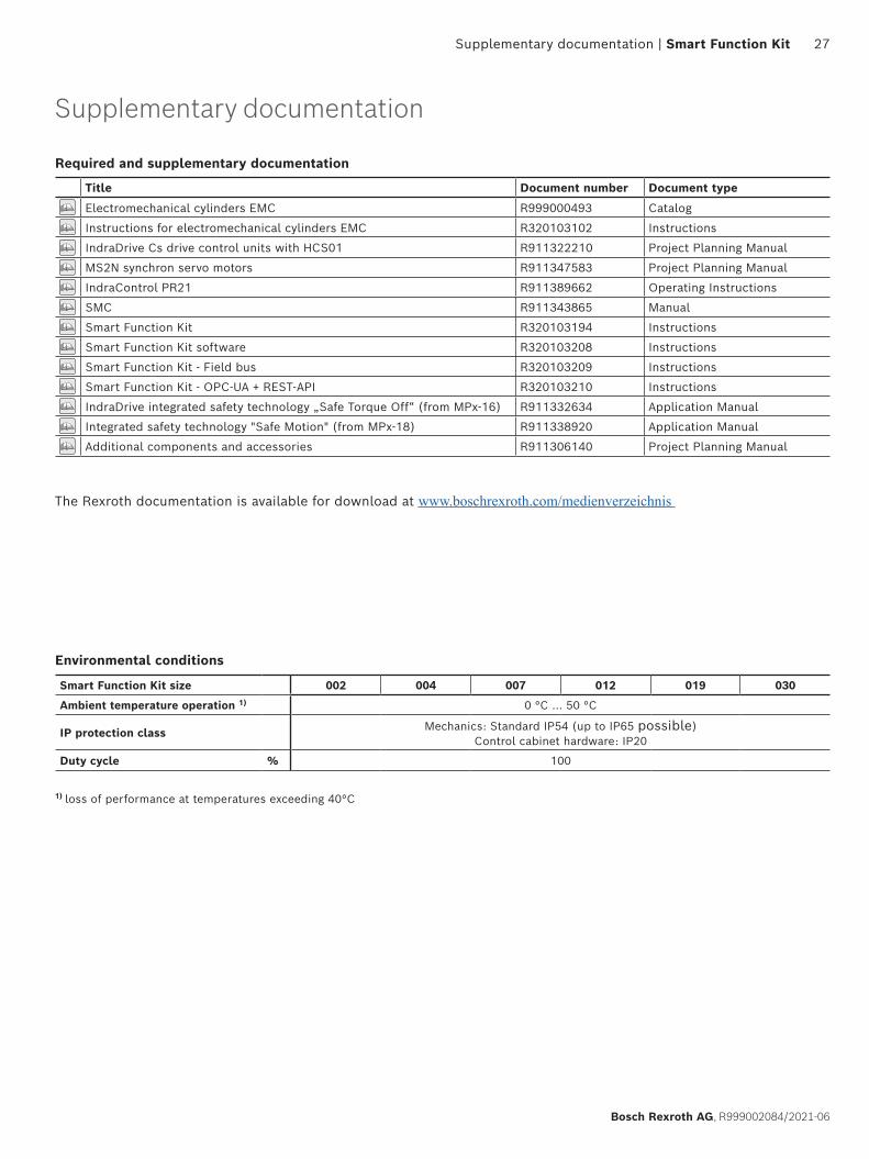
Environmental conditions
Smart Function Kit size 002 004 007 012 019 030
Ambient temperature operation 1) 0 °C ... 50 °C
IP protection class Mechanics: Standard IP54 (up to IP65 possible)Control cabinet hardware: IP20
Duty cycle % 100
Required and supplementary documentation
Title Document number Document type
Electromechanical cylinders EMC R999000493 Catalog
Instructions for electromechanical cylinders EMC R320103102 Instructions
IndraDrive Cs drive control units with HCS01 R911322210 Project Planning Manual
MS2N synchron servo motors R911347583 Project Planning Manual
IndraControl PR21 R911389662 Operating Instructions
SMC R911343865 Manual
Smart Function Kit R320103194 Instructions
Smart Function Kit software R320103208 Instructions
Smart Function Kit - Field bus R320103209 Instructions
Smart Function Kit - OPC-UA + REST-API R320103210 Instructions
IndraDrive integrated safety technology „Safe Torque Off“ (from MPx-16) R911332634 Application Manual
Integrated safety technology "Safe Motion" (from MPx-18) R911338920 Application Manual
Additional components and accessories R911306140 Project Planning Manual
1) loss of performance at temperatures exceeding 40°C
27 Supplementary documentation | Smart Function Kit
Bosch Rexroth AG, R999002084/2021-06
Supplementary documentation
The Rexroth documentation is available for download at www.boschrexroth.com/medienverzeichnis

Find your local contact person here:www.boschrexroth.com/contact
Bosch Rexroth AGErnst-Sachs-Straße 10097424 Schweinfurt, GermanyTel. +49 9721 937-0www.boschrexroth.com
R999002084/2021-06© Bosch Rexroth AG 2021Subject to modifications!
The information provided serves only to describe the product.No statements concerning a certain condition or suitability for a certainapplication can be derived from our information. The information givendoes not release the user from the obligation of their own judgment andverification. Our products are subject to natural wear and aging.