Embed Size (px)
Citation preview

CFAS Enterprises Inc.After Market Utility Power Equipment BrokerageMailto:[email protected] URL: http://CFASPower.com/Reciprocating URL: http://CFASPower.com/Recips.html
GTG_1189RC_Fm5N_50Hz.doc
Two (2) 23 MW GE Frame 5 N Gas Turbine Power Generators 23Mw/10,5 kV- 50 Hz
Offer Ref. No. GT-274SCOPE OF SUPPLY
Asking price: $6.825MM Each
1 Gas Turbine Generators and Associated Equipment
1.1 Mechanical Equipment and Systems
One (1) GE Model Frame 5341 single shaft, heavy-duty industrial gas turbine, packaged for outdoor operation and complete with the following major on-base systems:
Starting System

Diesel engine starting device including driving clutch, torque converter and electro-hydraulic rotor turning device
Combustion SystemStandard multi combustor combustion system for natural gas fuel firing.
Fuel System
Dual Fuel Fire System in accordance with GE specification.
Lube, Hydraulic and Trip Oil System
On-base, self-contained, lubricating and hydraulic oil system to GE standard format, sized to meet the requirements of the gas turbine, accessory gearbox, load gearbox and generator and complete with:
- Lube oil filter(s) (duty and standby).- Lube oil cooler(s).- Positive displacement gear type, main lube oil pump.- Shaft driven main hydraulic oil pump.- AC and DC electric motor driven auxiliary and emergency lubricating oil pumps.- Stainless steel lube oil pipework downstream of the lube oil filters.
Fire Protection System
CO2 fire protection and detection system for the accessory, turbine and load gearbox compartments and comprising nozzles, heat detectors, piping and wiring and 100% storage bottles to be located in a rack immediately adjacent to the gas turbine.Enclosure and Walkways
Baseplate mounted acoustic enclosure, complete with single ventilation fan, to meet average 95 dB(A) at 1 metre.Set of walkways surrounding the gas turbine package.
Control and Instrumentation
Velocity type vibration detectors, on both the gas turbine and generator.
Couplings
Gear type accessory coupling with coupling guard.Gear type load coupling with coupling guard.One (1) High precision cut, single helical, vertically offset speed reduction load
gearboxes, sized to match the gas turbine rating through the operating ambient range and located on the generator baseplate.
One (1) Set, gas turbine air inlet ducting complete with:
Inlet elbow.Silencer section.Plain duct section.

Support steelwork/access.Air inlet filter house, of the pulse clean design.
One (1) Gas turbine water/air fin fan cooler of the forced draught type, mounted on the gas turbine unit.
One (1) Vertical Exhaust complete with transition piece silencer duct.
1.2 Electrical Equipment and Systems
One (1) Air filter cooled, synchronous 10,5 kV, 3 phase, 50 Hz 0.85 pF generator, packaged for outdoor operation complete with the following major items of equipment.
i) Static excitation system.ii) HV terminals suitable for non-phase segregated bus duct connection.
One (1) Air conditioned local control cab, containing the LV power, control and protection equipment for the gas turbine generator comprising the following:
One (1) SentinelTM C turbine control system.One (1) motor control centre (AC and DC sections).
1.3 Foundations
Provision of the foundation loading data to allow the client to design and provide the foundation block.
1.4 New Supply Miscellaneous Equipment and Services
One (1) Set of cables for interconnections between all electrical and controls equipment supplied on base.
TERMINAL POINTS
Combustion Air : Inlet air inlet filter house.
Exhaust : Exit from the gas turbine exhaust system flange.
Fuel : Inlet flange to the on-base fuel system.
Cooling Water : Fill connection on fin-fan cooler header tank.
Lube Oil : Make up flange connection on gas turbine on-base reservoir

Ventilation : Inlet/outlet grilles on unit enclosure.
Drains and Vents : On-base flange/connections, lube oil vent outlets, gas vent outlets.
Electrical (HV) : 11 kV outgoing terminals of generator transformer.
Electrical (LV) : LV power terminals on each junction box for external interfaces by others.
Control System : Control terminals on each junction box for external interfaces by
others.
Earthing : Earthing boss connections (2 per item of equipment).
EXCLUSIONS TO SCOPE OF SUPPLY
Certain equipment and services are excluded from our scope of supply and are the responsibility of the purchaser or other sub-contractor. These exclusions include, but are not specifically limited to:
1. All works except those specified in the scope of supply.
2. Fuel in sufficient quantity to our stated terminal point and in accordance with GE standard specification.
3. Lubricating oil of suitable quality and quantity, to our stated terminal point and in accordance with GE standard specification GEI 28143A.
4. Cooling water of suitable quality and quantity, to our stated terminal point and in accordance with GE standard specification GEI 41004G.
5. All necessary work on site other than specifically stated in our scope of supply, such as, but not limited to:
- Fuel forwarding/conditioning skids.
- Fuel supply piping.
- Generator switchgear, for the protection of the generator and synchronising to the existing power distribution system.
- Site ducting and drains etc.
6. Provision of all off-base materials and equipment other than those specifically listed in our scope of supply, including:

- All electrical equipment, control systems, HV, MV, LV and control cabling and fittings beyond the stated terminal points.
- All earthing and lightning protection systems beyond the stated terminal points.
- All station common services including fire protection, lighting, compressed air, etc.
- All essential AC power standby supplies.
7. Design and execution of all civil works including piling, foundations hardware, buildings and site works of any nature, including grouting of all skids and sub-sole plates.
8. The cost of all taxes, duties, permits and any other fees associated with the importation and management, for the importing of the gas turbine power plant.
9. Any costs incurred by the "Purchaser", "Purchaser's Representative", or "Engineer" in carrying out inspections or attending tests, etc. at the contractor's works or those of his sub-contractors.
10. All Purchaser's and End User's own and Government imposts, duties, taxes and fees of any nature on any goods, services and/or personnel within or imported into the new job site.
11. The site environmental conditions and the application of any local or national codes or standards have not been made available; the gas turbine based power plant offered is therefore based on a standard power plant design and product supply.
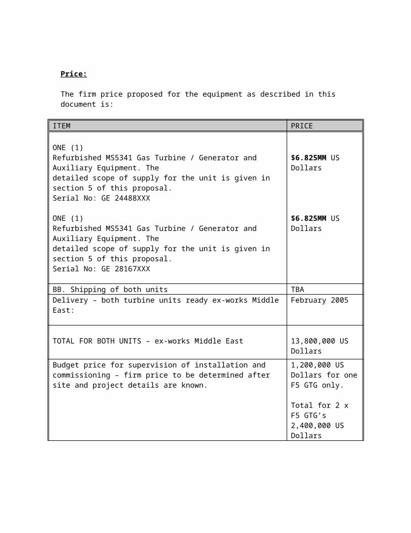
Price:
The firm price proposed for the equipment as described in this document is:
ITEM PRICE
ONE (1) Refurbished MS5341 Gas Turbine / Generator and Auxiliary Equipment. The detailed scope of supply for the unit is given in section 5 of this proposal. Serial No: GE 24488XXX
ONE (1) Refurbished MS5341 Gas Turbine / Generator and Auxiliary Equipment. The detailed scope of supply for the unit is given in section 5 of this
$6.825MM US Dollars
$6.825MM US Dollars

proposal. Serial No: GE 28167XXX
BB. Shipping of both units TBADelivery – both turbine units ready ex-works Middle East: February 2005
TOTAL FOR BOTH UNITS – ex-works Middle East 13,800,000 US
Dollars
Budget price for supervision of installation and commissioning – firm price to be determined after site and project details are known.
1,200,000 US Dollars for one F5 GTG only.
Total for 2 x F5 GTG’s2,400,000 US Dollars
Terms of Payment
The following terms of payment are to be incorporated into the contract to be signed in relation to this project.
Fifty percent of the contract value upon signature of the contractFifty percent of the contract value upon notification the gas turbines are available for despatch ex-works Middle East.
Please note that the contract price does not include any taxes levied by the authorities of the receiving country or state, which the client is obliged to pay. If such taxes are levied, the contract price shall be adjusted accordingly.
This proposal is submitted on the understanding that the under noted qualifications shall form part of the contract:
WarrantyThe defects liability period for the total plant supply by TS within this contract shall be twelve months after start up of the unit or 18 months from date of delivery, whichever is soonest.
EQUIPMENT AND WORKSCOPE
REFURBISHMENT AND OVERHAUL SERVICES OF EQUIPMENT
1. INTRODUCTION Page 2
2. SERVICES Page 2
3. PROJECT MANAGEMENT Page 2
4. PERFORM STANDARD FLANGE TO FLANGE MAJOROVERHAUL OF THE GAS TURBINE CORE Page 2
5. REFURBISH THE GAS TURBINE LOAD AND ACCESSORY COMPARTMENTS Page 2
6. GENERATOR OVERHAUL Page 3
7. AIR INLET & EXHAUST SYSTEMS Page 3
8. COOLING WATER FIN FAN & PUMP SKID Page 3
9. FIRE PROTECTION Page 3
10. CONTROL SYSTEMS Page 3

1. IntroductionThe following is a general description of the proposed refurbishment and overhaul services of the gas turbine generator packaged equipment, included in our proposal.
2. Services The package units to be refurbished have been decommissioned, dismantled prior to removal from site. The unit has been completely overhauled.
3. Project Management A dedicated single point of contact - Project Manager – will be appointed and allocated to co-ordinate all activities of the project.
4. Perform a Standard Flange-to-Flange Major Overhaul of the Gas Turbine Core, and carry out all modifications on base which are necessary.A full major overhaul of the Gas Turbine will be carried out. The following components are removed and replaced with new: - Compressor Rotor blades- Compressor stator blades- First Stage Buckets- Second stage Buckets- First stage Nozzle assemblies (refurbished)- Second stage Nozzle assemblies (refurbished)- Inlet Guide Vanes
5. Refurbish the Gas Turbine Load and Accessory Compartment. Drain all oils from the accessory and load compartment tanks.Clean the accessory/ turbine and load/ compartment.Function test all package motors.Calibrate all pressure and temperature gauges.Carry out a service of the turbine diesel engine starting means. Open and inspect the Accessory Gear box.Replace Bearings and Seals as required.Open and inspect the Load Gear box.Replace bearings and seals as required.Replacement rotating elements for the gearboxes is not included.Function test lube oil tank heaters.Clean and pressure test lube oil tube bundles.Supply and fit new lube oil filters.Supply and fit new control oil filters.Supply and fit new Hydraulic Oil filters.Inspect the Accessory coupling and supply replacement coupling bolts.Inspect the load coupling and supply replacement coupling bolts.Completely rewire the instrumentation /control devices and power supplies.All devices will be calibrated and tested for further use.Rebuild accessory and turbine compartment bases.Paint bases.
6. Generator Overhaul

Remove generator rotor.Inspect generator rotor.Generator rotor IR and PI checks.Generator stator IR and PI checks.Check stator and rotor wedges.Replace/repair Generator bearings and oils seals as required.Clean and paint the package enclosure.Calibrate existing on base pressure/temperature instrumentation.Check generator CT’s and VT’sGenerator rotor end ring replacement.
Note: Not included in Generator Overhaul – and therefore NOT included in the quoted price: Generator Rotor and/or Stator rewind.
7. Air Inlet and Exhaust Systems New air intake ducting is included in the supply.New exhaust ducting is included in the supply.
8. Cooling water fin fan and pump skid New off base fin fan cooler, rated for an ambience up to 55 Degrees C.
9. Fire Protection System New CO2 fire protection system has been included in our scope of supply.
10. Control SystemThe Mark two speedtronic control system is replaced by the latest state of the art PLC Sentinel system. In addition the control cab has also been refurbished with a new suite of panels including the generator control / protection panel, MCC, battery charger and battery pack.

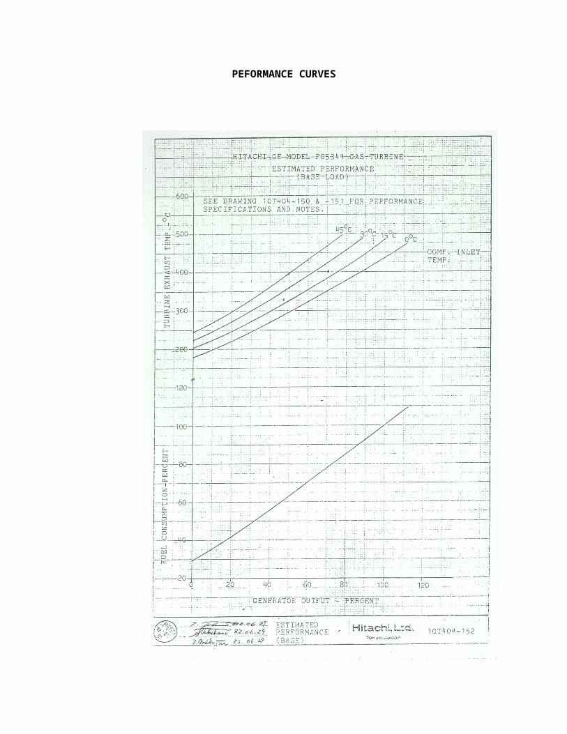
SECTION 9ANTICIPATED PERFORMANCEAND PERFORMANCE CURVES
9.1 Anticipated Performance
9.1.1 The performance of the fully serviced and “0” houred Gas turbine is anticipated as follows:
Gross Load Output : 23,000 kW measured at generator terminals.
Gross Heat Rate : 12,890 BTU/KW-HR at the above measured loads.
These performance figures will be obtained when the following operating/ambient conditions apply:
Gas Turbine Unit : PG5341Ambient Temperature : 15°CAtmospheric Pressure : 1013 mbar (a)Humidity : 60%Inlet Duct Losses : 4 inches WGExhaust Duct Losses : 2 inches WGFuel : Natural Fuel Gas to GE
Specification GEI 41040F
9.1.2 This anticipated performance is subject to the following:
(i) Each test to establish the performance figures shall be made when:
(a) The gas turbine is commissioned and is in a clean and in proper working condition.
(b) Using a fuel of an acceptable quality as specified above.(c) The contractor is witness to the test.
(ii) The tests, procedure and method of measurement (including margins to cover errors in observation and measurement) to establish the operating specifications shall be mutually agreed before commencement of the tests. Prior to commencing the actual testing the main contractor will provide specific customised data sheets for recording the unit parameters.
(iii) Method of measurement of ambient air temperature and ambient pressure shall be agreed.
(iv) All performance tests shall, unless otherwise agreed, be carried out immediately following the date that the gas turbine is ready for such tests.

PEFORMANCE CURVES


s


![INDEX [cfaspower.com]cfaspower.com/GTG_1627GR_Fm6CC_50… · Web view · 2013-04-08LA, SC, PT, CT CUBICLE 3. 6.2.4. NEUTRAL GROUNDING ... 127 0C 127 0C. ... As required Actual](https://img.pdfslide.net/doc/110x75/5adf3aeb7f8b9ad66b8c9227/index-web-view2013-04-08la-sc-pt-ct-cubicle-3-624-neutral-grounding.jpg)