Embed Size (px)
Citation preview

FOR SERVICE TECHNICIAN’S USE ONLY
FOR SERVICE TECHNICIAN’S USE ONLY
DANGER
Electrical Shock Hazard
Only authorized technicians should perform diagnostic voltage measurements.
After performing voltage measurements, disconnect power before servicing.
Failure to follow these instructions can result in death or electrical shock.
WARNING
Electrical Shock Hazard
Disconnect power before servicing.
Replace all parts and panels before operating.
Failure to do so can result in death or electrical shock.
PRECAUTIONS TO BE OBSERVED BEFORE AND DURING SERVICING TO AVOID POSSIBLE
EXPOSURE TO EXCESSIVE MICROWAVE ENERGYa. Do not operate or allow the oven to be operated with the door
open.b. Make the following safety checks on all ovens to be serviced
before activating the magnetron or other microwave source, and make repairs as necessary:1. Interlock Operation2. Proper Door Closing3. Seal and Sealing Surfaces (Arcing, Wear and Other Damage)4. Damage to or Loosening of Hinges and Latches5. Evidence of Dropping or Abuse
c. Before turning on microwave power for any service test or inspection within the microwave generating compartments, check the magnetron, waveguide or transmission line, and cavity for proper alignment, integrity and connections.
d. Any defective or misadjusted components in the interlock, monitor, door seal, and microwave generation and transmission systems shall be repaired, replaced, or adjusted by procedures described in service manual before the oven is released to the owner.
e. A microwave leakage check to verify compliance with the Federal Performance Standard should be performed on each oven prior to release to the owner.
f. Do not attempt to operate the oven if the door glass is broken.
Voltage Measurement Safety InformationWhen performing live voltage measurements, you must do the following:
■ Verify the controls are in the off position so that the appliance does not start when energized.
■ Allow enough space to perform the voltage measurements without obstructions.
■ Keep other people a safe distance away from the appliance to prevent potential injury.
■ Always use the proper testing equipment.
■ After voltage measurements, always disconnect power before servicing.
Tech Sheet Do not discard
W10721755A
FOR SERVICE TECHNICIAN’S USE ONLY
2
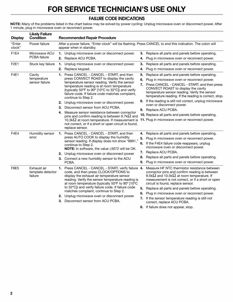
FAILURE CODE INDICATIONSNOTE: Many of the problems listed in the chart below may be solved by power cycling: Unplug microwave oven or disconnect power. After 1 minute, plug in microwave oven or reconnect power.
DisplayLikely Failure Condition Recommended Repair Procedure
“Enter clock”
Power failure After a power failure, “Enter clock” will be flashing. Press CANCEL to end this indication. The colon will appear when in standby.
F1E4 Microwave ACU PCBA failure
1. Unplug microwave oven or disconnect power.2. Replace ACU PCBA.
3. Replace all parts and panels before operating.4. Plug in microwave oven or reconnect power.
F2E1 Stuck key failure 1. Unplug microwave oven or disconnect power.2. Replace keypad.
3. Replace all parts and panels before operating.4. Plug in microwave oven or reconnect power.
F4E1 Cavity temperature sensor failure
1. Press CANCEL - CANCEL - START, and then press CONVECT ROAST to display the cavity temperature sensor reading. Verify the sensor temperature reading is at room temperature (typically 50ºF to 90º [10ºC to 32ºC]) and verify failure code. If failure code matches complaint, continue to Step 2.
2. Unplug microwave oven or disconnect power.3. Disconnect sensor from ACU PCBA.4. Measure sensor resistance between connector
pins and confirm reading is between 9.7kand 10.3kat room temperature. If measurement is not correct, or if a short or open circuit is found, replace sensor.
5. Replace all parts and panels before operating.6. Plug in microwave oven or reconnect power.7. Press CANCEL - CANCEL - START, and then press
CONVECT ROAST to display the cavity temperature sensor reading. Verify the sensor temperature reading. If the reading is correct, stop.
8. If the reading is still not correct, unplug microwave oven or disconnect power.
9. Replace ACU PCBA.10. Replace all parts and panels before operating.11. Plug in microwave oven or reconnect power.
F4E4 Humidity sensor error
1. Press CANCEL - CANCEL - START, and then press AUTO COOK to display the humidity sensor reading. If display does not show “8891,” continue to Step 2.NOTE: In software, the value 3072 will be OK.
2. Unplug microwave oven or disconnect power.3. Connect a new humidity sensor to the ACU
PCBA.
4. Replace all parts and panels before operating.5. Plug in microwave oven or reconnect power.6. If the F4E4 failure code reappears, unplug
microwave oven or disconnect power.7. Replace ACU PCBA.8. Replace all parts and panels before operating.9. Plug in microwave oven or reconnect power.
F8E5 Exhaust air template detector failure
1. Press CANCEL - CANCEL - START, verify failure code, and then press CLOCK/OPTIONS to display the exhaust air temperature sensor reading. Verify the sensor temperature reading is at room temperature (typically 50ºF to 90º [10ºC to 32ºC]) and verify failure code. If failure code matches complaint, continue to Step 2.
2. Unplug microwave oven or disconnect power.3. Disconnect sensor from ACU PCBA.
4. Measure HF NTC thermistor resistance between connector pins and confirm reading is between 9.5kand 10.5kat room temperature. If measurement is not correct, or if a short or open circuit is found, replace sensor.
5. Replace all parts and panels before operating.6. Plug in microwave oven or reconnect power.7. If the sensor temperature reading is still not
correct, replace ACU PCBA.8. If failure does not appear, stop.

FOR SERVICE TECHNICIAN’S USE ONLY
3
PRIMARY, SECONDARY, AND MONITOR INTERLOCK SWITCH CHECKOUT PROCEDURESIMPORTANT: Before checking the interlock switches, unplug microwave oven or disconnect power. Be sure to disconnect all of the wires at the switch being tested before making any continuity readings.NOTE: The Secondary Interlock Switch is mounted in the door lock switch cradle independent of the Monitor Interlock Switch and Primary Interlock Switch. The Monitor Interlock Switch and the Primary Interlock Switch can be identified by the wire colors that are connected to the terminals of the switches. See the chart below for wire color designation.
(+) Continuity (-) No ContinuityNOTE: These diagrams are not intended to show a complete circuit; they represent the position of switches during “DOOR OPEN” or “DOOR CLOSED” (continuity checks only).
Door Closed Door Open
Switch Check By Door Open Door Closed
Primary Interlock 1. Unplug microwave oven or disconnect power.2. Disconnect the wires at the Primary Interlock Switch.3. Check from the common terminal (black/brown wires) to the normally open
terminal (black/white wires).
- +
1. Unplug microwave oven or disconnect power.2. Disconnect the wires at the Primary Interlock Switch.3. Check from the common terminal (black/brown wires) to the normally closed
terminal (orange wire).
+ -
Monitor Interlock 1. Unplug microwave oven or disconnect power.2. Disconnect the wires at the Monitor Interlock Switch.3. Check from the common terminal (white/red wires) to the normally
closed terminal (blue/white wires).
+ -
Secondary Interlock 1. Unplug microwave oven or disconnect power.2. Disconnect the wires at the Secondary Interlock Switch.3. Check from the common terminal (white/blue wires) to the normally
open terminal (blue/blue wires).
- +
N(NO)(NC)
MonitorInterlockSwitch
PrimaryInterlockSwitch
(NC)(NO)
SecondaryInterlockSwitch
(NC)(NO)P5-4 P5-2
L N(NO)(NC)
MonitorInterlockSwitch
PrimaryInterlockSwitch
(NC)(NO)
SecondaryInterlockSwitch
(NC)(NO)P5-4 P5-2
L

FOR SERVICE TECHNICIAN’S USE ONLY
4
NOT HEATING TROUBLESHOOTING INSTRUCTIONIMPORTANT: High voltage is present at the magnetron and high voltage capacitor terminals. Avoid direct contact when power is connected to these components to avoid serious injury or possible death. Always be sure that the high voltage capacitor is discharged before accessing any of these components.For a no-heat condition, refer to the following step-by-step instructions:1. Unplug microwave oven or disconnect power.2. Discharge the high voltage capacitor.3. Disconnect the high voltage transformer primary windings. 4. Attach the voltmeter leads to the high voltage transformer
primary input wires. 5. Plug in microwave oven or reconnect power.6. Close door and program the microwave oven to operate for
30 seconds. 7. Press START. 8. Check the input voltage at the high voltage transformer primary
input wires. If the voltage is not close to the rating voltage 120 +/- 15 VAC, unplug microwave oven or disconnect power. Check the circuitry as follows:■ Measure resistance of the fuse, microswitches and
thermostats. Replace any failed components (refer to the wiring diagram).
■ Check for loose terminals (refer to the wiring diagram). Check all of the terminals on the main route from the power supply to the high voltage transformer.
■ Check for loose or failed connectors on the ACU PCBA (P1, P2, P4). If these check out OK, plug in microwave oven or reconnect power.
■ Check for ACU PCBA failure. Refer to “ACU PCBA Pin Voltage Matrix.”
9. If the input voltage at the high voltage transformer primary input wires is close to the rating voltage 120 +/- 15 VAC, unplug microwave oven or disconnect power.
10. Check the power supply components. Refer to “Component Tests.”■ High voltage transformer
■ High voltage capacitor
■ High voltage diode
11. If the power supply components check out OK, check the connection between the magnetron and the high voltage transformer.
12. If all of the components check out OK, replace the magnetron.13. Reconnect the high voltage transformer primary windings.

FOR SERVICE TECHNICIAN’S USE ONLY
5
ACU PCBA PIN VOLTAGE MATRIXCheck for proper voltage by completing the following steps:1. Unplug microwave oven or disconnect power.2. Connect voltage measurement equipment to the terminals
listed below. (P1-2, P2-3 and P2-4 are neutral.)
3. Plug in microwave oven or reconnect power, and confirm voltage reading.
4. Unplug microwave oven or disconnect power.
NOTE: For 50V and over, the tolerance is +/-15V. For 0V, the tolerance is +/-3V.
NOTE: When checking voltage readings on ACU PCBA, connect the grounding test lead of voltmeter to ACU PCBA neutral wire. Use the positive test lead to probe connectors designated below.
CONNECTORS ON ACU PCBA
AbbreviationsHL– Hood Light N–Neutral
CL– Cavity LightFC– Forced Convection HF– Hood Fan L– Line Voltage
TT– Turntable Motor
NFS– Neutral for Switch
MW Oven Plugged In—Sitting Idle—ACV Readings
MW
Ove
n R
unni
ng
—A
CV
Rea
ding
s
Pin
Nam
e
Wire
Col
or
Pow
er O
n, D
oor
Clo
sed
Pow
er O
n, D
oor
Ope
n
Hoo
d Fa
n M
otor
—H
igh
Hoo
d Fa
n M
otor
—H
igh,
Doo
r O
pen
Hoo
d Fa
n M
otor
—M
ed-H
igh
Hoo
d Fa
n M
otor
—M
ed-H
igh,
Doo
r O
pen
Hoo
d Fa
n M
otor
—M
ediu
m
Hoo
d Fa
n M
otor
—M
ediu
m, D
oor
Ope
n
Hoo
d Fa
n M
otor
—Lo
w
Hoo
d Fa
n M
otor
—Lo
w, D
oor
Ope
n
Hoo
d Li
ght—
Hig
h
Hoo
d Li
ght—
Hig
h, D
oor
Ope
n
Hoo
d Li
ght—
Low
Hoo
d Li
ght—
Low
, Doo
r O
pen
MW
Ove
n S
tart
P1-1 (L) Brown 120 120 120 120 120 120 120 120 120 120 120 120 120 120 120
P1-2 (N) White 0 0 0 0 0 0 0 0 0 0 0 0 0 0 6
P2-1 (NFS) White 0 120 0 120 0 120 0 120 0 120 0 120 0 120 6.3
P2-2 (Door) Orange 0 120 0 120 0 120 0 120 0 120 0 120 0 120 50
P2-3 (N) Green 0 0 0 0 0 0 0 0 0 0 0 0 0 0 6
P2-4 (N) Blue 0 0 0 0 0 0 0 0 0 0 0 0 0 0 6
P4-1 (FC-V) Blue 0 120 0 120 0 120 0 120 0 120 0 120 0 120 0
P4-2 (TT) Red 0 0 0 0 0 0 0 0 0 0 0 0 0 0 120
P4-3 (CL) Green 0 120 0 120 0 120 0 120 0 120 0 120 0 120 120
P4-4 (HL) Yellow 0 0 0 0 0 0 0 0 0 0 120 120 68 68 0
P4-5 (HF) Black 0 0 120 120 88 88 78 78 64 64 0 0 0 0 0
P4-6 (HF-R) Gray 0 0 120 120 89 89 78 78 83 83 0 0 0 0 0
NOTE: There are purposely empty terminals between each of the numbered terminals on P1, P2 and P4 connectors.
ACU PCBA
P4
6 5 4 3 2 1 . . . . .
P1
2 1.P2
4 3 2 1 . . .LN

FOR SERVICE TECHNICIAN’S USE ONLY
6
TOUCH PANEL
Touch Panel and ACU PCBA Test
To initiate diagnostic routine:1. Plug in microwave oven or reconnect power and press CANCEL
button to standby (“:”). 2. Close door, then press CANCEL - CANCEL - START within
3 seconds.All display segments will be lit to indicate the test mode has been entered. In the upper left corner of the display, the condition of the ACU PCBA will be displayed (“GOOD”), or the most recent error code.
3. Open door. The model number will be displayed.4. Close door. All display segments will be lit.5. Press indicated key pad for correct display readout and beep. NOTE: If the CANCEL button is pressed during this diagnostic routine, you will exit the test mode.
Key Tables for Test Mode
*May be higher, depending on software upgrades at time of production.
Key Name FunctionUpper Row Display Buzzer
Start/Add 30 Sec Display UI SW and ACU PCBA SW version
UI: 00.02.01* and ACU: 03.00.02* (alternating)
1 beep
Clock/Options NTC sensor check 1 beep
Light off/high/low - key 03 1 beep
4 Speed Fan off/on
- key 04 1 beep
Kitchen Timer on/off
- key 05 1 beep
Keep Warm - key 06 1 beep
Turntable - key 09 1 beep
Cook Time - key 21 1 beep
Cook Power - key 22 1 beep
Reheat - key 24 1 beep
Defrost - key 25 1 beep
Soften/Melt - key 29 1 beep
Steam/Simmer - key 2D 1 beep
Veggie - key 2E 1 beep
Popcorn - key 30 1 beep
Baked Potato - key 31 1 beep
Snack Menu - key 38 1 beep
Kids Menu - key 37 1 beep
Key Name FunctionUpper Row Display Buzzer
Auto Cook Humidity sensor check Sensing 1 beep
Convect Roast Cavity temp sensor check Convect 1 beep
Convect Bake FC, Cavity Light, Turntable, Cooling Fan On
FC 1 beep
0 Microwave Oven (1000W), CL, TT and CF On
MW TB 1 beep
1 Cavity Light and Cooling Fan On
CL 1 beep
2 Cavity Light, Turntable and Cooling Fan On
CL TT 1 beep
3 - key 36 1 beep
4 - key 14 1 beep
5 - key 15 1 beep
6 Hood (Cooktop) Light On (High)
HL_HIGH 1 beep
7 Hood (Cooktop) Light On (Low)
HL_LOW 1 beep
8 Vent Fan On (High Speed) HF_HIGH 1 beep
9 Vent Fan On (Low Speed) HF_LOW 1 beep
Cancel Exit Test Mode : or xx.xx (display at 7 segment)
1 beep

FOR SERVICE TECHNICIAN’S USE ONLY
7
PARTS LAYOUT (NOT TO SCALE)
POWER OUTPUT MEASUREMENTThe power output of the magnetron can be measured using the following “Voltage Measurement” and “Output Test.” Before you perform the test:■ Make sure that the oven cavity is cool and clean.
■ Check the line voltage at the wall outlet while microwave oven is operating. See “Voltage Measurement at Power Source.”
Tools Needed
■ 2-cup measuring cup
■ Thermometer
■ Voltmeter/ohmmeter
Voltage Measurement at Power Source
1. Fill the measuring cup with 2 cups (500 mL) of tap water.2. Place in the center of the microwave oven cavity.3. Operate the microwave oven on high power for 1 minute.4. While the microwave oven is operating, measure the line
voltage at the power source. See “Measure Voltage” illustration.5. Verify the voltage is constant during microwave oven operation.
If voltage drops below 108V, contact a qualified electrician to check your electrical supply.
6. Make note of the voltage while the microwave oven is running, and proceed to the output test.
Measure Voltage
A. Hood fan motor assemblyB. FC thermistorC. Cavity light D. Cavity light holder E. FC thermoactuatorF. Motor capacitor G. Power resistor H. H.V. capacitor I. H.V. diode
J. Magnetron thermostat—opens at 293ºF (145ºC), closes at 230ºF (110ºC)
K. Magnetron L. H.V. transformer
M. Turbo fuse holderN. Turbo fuse (20 amp)O. Cooling fan motorP. HF NTC thermistor
Q. ACU and UI PCBAR. Touch panelS. Secondary interlock
switchT. Monitor interlock switchU. Primary interlock switchV. Turntable motor
W. Hood (cooktop) light X. Hood (cooktop) light
holderY. AC line filter boardZ. Main fuse (20 amp)
AA. FC thermostat—opens at 329ºF (165ºC), closes at 257ºF (125ºC)
AB. FC motorAC. FC ring heaterAD. Humidity sensorAE. Cavity thermostat—
opens at 329ºF (165ºC), non-resettable
V
AB
C DE
F
G
H
I
OP
JK
L
W
U
Z
S
X
R
MN
Y
QT
AA
AB
AC
AEAD
A. House power supply wall outletB. Voltmeter/ohmmeter test leadsC. Microwave oven plug
C
AB

FOR SERVICE TECHNICIAN’S USE ONLY
8
Output Test
1. Fill the measuring cup with 2 cups (500 mL) of 70ºF (21ºC) tap water.
2. Stir the water with the thermometer to ensure uniform temperature. Add warm or cool water to bring the water to the correct temperature.
3. Place the measuring cup in the center of the microwave oven cavity.
4. Operate the microwave oven on high power for 1 minute.5. Remove the measuring cup and stir the water with the
thermometer for about 20 seconds.6. Record the temperature of the water.7. Refer to the model serial tag on the microwave oven to acquire
wattage output rating of the microwave oven.
8. Using the following chart, determine if the output of the microwave oven is within the range listed based on the line voltage and wattage rating of the microwave oven.
COMPONENT TESTS
Water Temperature for Line Voltage and Wattage Rating
Voltage 700W 1000W 1200W
120V 96ºF to 102ºF (36ºC to 39ºC)
110ºF to 116ºF (43ºC to 47ºC)
124ºF to 130ºF (51ºC to 54ºC)
108V 91ºF to 97ºF (33ºC to 36ºC)
101ºF to 107ºF (38ºC to 42ºC)
111ºF to 117ºF (44ºC to 47ºC)
IMPORTANT:
■ Unplug microwave oven or disconnect power.
■ Discharge the high-voltage capacitor and remove the lead wires from the primary winding of the high-voltage transformer before conducting any of the following tests.
■ Remove the lead wires from the related component before conducting any of the following tests.
■ All operational checks using microwave energy must be done with the microwave oven loaded with a minimum of 8 oz (250 mL) of water in a microwave-safe container.
■ Conduct a microwave energy test after performing any tests or repairs to the microwave oven.
■ Check that all wire leads are in the correct positions before operating the microwave oven.
■ Grasp wire connectors when removing the wire leads from microwave oven parts.
■ All testing must be done with an ohmmeter having a sensitivity of 20,000 ohms per volt DC or greater, and powered by at least a 9-volt battery.
Components Test/Results
H.V. Transformer 1. Unplug microwave oven or disconnect power.2. Remove wire leads.3. Measure resistance:
■ Primary winding: Less than 0.5 ohm (approximate)
■ Secondary winding: 120 ohms (approximate)
■ Filament winding: 0 ohms
■ Primary winding to grounding: Normal: Infinite
■ Filament winding to grounding: Normal: Infinite
Magnetron 1. Unplug microwave oven or disconnect power.2. Remove wire leads.3. Measure resistance:
■ Filament terminal: Normal: Less than 1 ohm
■ Filament to chassis: Normal: Infinite
Primary
Filament(orange/red wires)
Secondary (white wire - ground to transformer case)

FOR SERVICE TECHNICIAN’S USE ONLY
9
H.V. Capacitor 1. Unplug microwave oven or disconnect power.2. Remove wire leads.3. Measure resistance:
■ Terminal to terminal: Normal: Momentarily indicates several ohms, and then gradually returns to infinite.
■ Terminal to case: Normal: Infinite
Motor Capacitor 1. Unplug microwave oven or disconnect power.2. Remove wire leads.3. Measure motor capacitor:
■ Normal: Momentarily 0 ohms, then goes to infinite
Cooling Fan Motor 1. Unplug microwave oven or disconnect power.2. Remove wire leads.3. Measure resistance:
■ Normal: 40 to 60 ohms (approximate)
H.V. Diode NOTE: Some inexpensive meters may indicate infinite resistance in both directions.1. Unplug microwave oven or disconnect power.2. Measure resistance:
■ Forward: Normal: Continuity
■ Reverse: Normal: Infinite
Turntable Motor 1. Unplug microwave oven or disconnect power.2. Remove wire leads.3. Measure resistance:
■ Normal: 2.8k ohms (approximate)
FC Motor 1. Unplug microwave oven or disconnect power.2. Remove wire leads.3. Measure resistance:
■ Normal: 23 to 25 ohms
Humidity Sensor 1. Unplug microwave oven or disconnect power.2. Remove the 3-pin connector from the electronic control (P6).
NOTE: Do not remove the attached resistor, which is used for internal resistance calibration.
3. Measure resistance across pins 1 and 3, and across pins 2 and 3:■ Normal: 2.8k ohms (approximate) at 77ºF (28ºC) +/- 18ºF (-10ºC)
Hood Exhaust Fan Motor 1. Unplug microwave oven or disconnect power.2. Remove wire leads.3. Measure resistance:
■ High Speed—Normal: Red (RD) and Blue (BU) wires: 70 to 100 ohms (approximate); Blue (BU) and Black (BK) wires: 30 to 60 ohms (approximate)
■ Low Speed—Normal: Red (RD) and Blue (BU) wires: 70 to 100 ohms (approximate); Blue (BU) and White (WH) wires: 50 to 80 ohms (approximate)
Components Test/Results
WHRDBK
Resistor

FOR SERVICE TECHNICIAN’S USE ONLY
10
HF NTC Thermistor 1. If “NTC SHORT, CALL FOR SERVICE” or “NTC OPEN, CALL FOR SERVICE” scrolls on display, unplug microwave oven or disconnect power.
2. Measure resistance:■ Normal: 10k ohms +/- 5% at 77ºF (25ºC)
FC Thermistor 1. Unplug microwave oven or disconnect power.2. Remove wire leads.3. Measure resistance:
■ Normal: 230k +/- 20% ohm at 77ºF (25ºC)
FC Ring Heater 1. Unplug microwave oven or disconnect power.2. Remove wire leads.3. Measure resistance:
■ Normal: 9 +/- 3 ohms
FC Thermoactuator 1. Unplug microwave oven or disconnect power.2. Remove wire leads.3. Measure resistance:
■ Normal: 1.2k +/- 0.5k ohms
Power Resistor 1. Unplug microwave oven or disconnect power.2. Remove wire leads.3. Measure resistance:
■ Normal: 20 ohms/25W
AC Line Filter Board 1. Unplug microwave oven or disconnect power.2. Remove wire leads.3. Measure resistance:
■ Normal: L-IN to L-OUT (coil): Less than 1 ohm; N-IN to N-OUT (coil): Less than 1 ohm
Thermostats NOTE: Refer to “Parts Layout” for opening and closing temperatures.1. Unplug microwave oven or disconnect power.2. Remove wire leads.3. Measure continuity:
■ Normal: Continuity
Components Test/Results
3551
P5
V0
52
ES
UF
A0
2
L NI-
L TUO-
N TUO-N NI-
FC / Magnetron/ CavityThermostat

FOR SERVICE TECHNICIAN’S USE ONLY
11
SCHEMATIC DIAGRAM
HL
CL
HF
P5
-2
P5-5
ACU
PC
BA
P5-4
TT P5
-1
12
Doo
r
NFS
CF
TTN
N
FCM
RDRD
FC-V
HL
LR
HF
CL
N
H
BU
P6-3
YL
RD
BUYL
RDP6-5
P6-1
P6-2
P1/P
2/P4
/P5/
P6/P
9/P1
2: C
onne
ctor
sH
LH
ood
(Coo
ktop
)Li
ght
FCM
Forc
ed
Con
vect
ion
Mot
or
CL
Cav
ity
Ligh
t
TTTu
rnta
ble
Mot
or
Hoo
d Fa
n M
otor
BK WH
BUYL R
DHF
BK:
Blac
kO
R:
Ora
nge
BU:
Blue
YL:
Yello
wR
D:
Red
GN
:G
reen
WH
:W
hite
GY:
Gra
yBR
:Br
own
YL/G
N:
Yello
w/G
reen
Dw
g. N
o.: M
U-1
40-T
Con
ditio
n: D
oor O
pen.
Sym
bol N
otes
:BK
Wire
Col
or -
Blac
kP6
-1Pi
n N
o. -1
Con
nect
or N
ame
AC 120V / 125V 60 HzPower Cord
GNWH BK
LN
FCTH
Cav
ity
Ther
mos
tat
CL
Rel
ay49
01TT
Rel
ay49
02
MW
Rel
ay49
03
MW
Tur
bo
Rel
ay 4
913
Dio
de 6
908
Mag
netro
n Th
erm
osta
t
Mag
netro
n
Seco
ndar
y In
terlo
ck S
witc
h
Prim
ary
Inte
rlock
Sw
itch
Monitor Interlock
Switch
FC Motor Relay 4914
HL Relay 4909
Tria
c79
15
HL Relay 4910
FC Relay 4904
FC S
enso
r
HF Relay 4911
P4-1
BK
BK
BKBK
BK
BK
P1-2
WH
WH
WH
WH
WH
WH
WH
WH
RD
RD
P4-4
OR
RD
RD
P1-1
BU
BU
BU BU
BU
BU
BU
P4-5
GN
GN
P4-6GY GY
P4-3
P4-2
BR
P2-2
P2-4
P2-3
P2-1
YL
YL/GN
YL/GN
P9
BK
WH
WH
WH
R
P6
P12
No
Nc
BUBU
FA F
33K
AC L
ine
Filte
r Boa
rd
RC
x
Cy
Cy
Mai
n Fu
se
20 Amp
N-In
N-O
ut
L-In
L-O
ut
L L
12
34
FC Heater
Turbo Fuse 20 Amp
WhiteTab
WhiteTab
Golden Tab
Golden Tab
Mot
or
Cap
acito
r
Power Resistor
SMPSFuse
Blac
k Tu
be
Black Tube
Red
Tub
e
H.V
. C
apac
itor H
.V.
Dio
deH
.V.
Tran
sfor
mer
Hum
idity
Se
nsor
HF
NTC
Th
erm
isto
r
ACU
PC
BA: A
pplia
nce
Con
trol U
nit P
rinte
d C
ircui
t Boa
rd A
ssem
bly
FC Thermostat

FOR SERVICE TECHNICIAN’S USE ONLY
W10721755A© 2014. All rights reserved.
7/14FOR SERVICE TECHNICIAN’S USE ONLY