Embed Size (px)
Citation preview
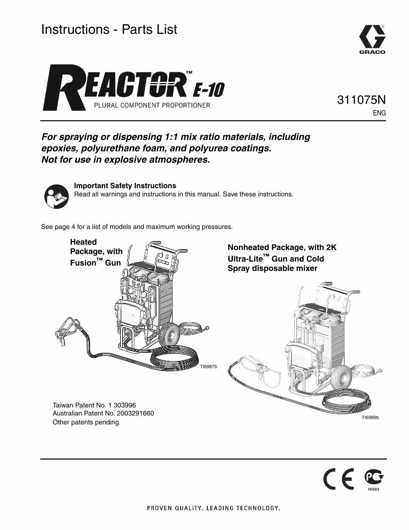
Instructions - Parts List
For spraying or dispensing 1:1 mix ratio materials, including epoxies, polyurethane foam, and polyurea coatings. Not for use in explosive atmospheres.
See page 4 for a list of models and maximum working pressures.
Important Safety InstructionsRead all warnings and instructions in this manual. Save these instructions.
Nonheated Package, with 2K Ultra-Lite™ Gun and Cold Spray disposable mixer
TI6989b
Heated Package, with Fusion™ Gun
TI6987b
Taiwan Patent No. 1 303996Australian Patent No. 2003291660Other patents pending.
311075NENG
2 311075N
ContentsRelated Manuals . . . . . . . . . . . . . . . . . . . . 3Systems . . . . . . . . . . . . . . . . . . . . . . . . . . . 3Models . . . . . . . . . . . . . . . . . . . . . . . . . . . . 4Warnings . . . . . . . . . . . . . . . . . . . . . . . . . . 5Overview . . . . . . . . . . . . . . . . . . . . . . . . . . . 8Isocyanate Hazard . . . . . . . . . . . . . . . . . . . 9Foam Self-ignition . . . . . . . . . . . . . . . . . . . 9Moisture Sensitivity of Isocyanates . . . . . 9Keep Components A and B Separate . . 10Changing Materials . . . . . . . . . . . . . . . . . 10Component Identification . . . . . . . . . . . . 11Controls and Indicators . . . . . . . . . . . . . 13
Motor/Pump Control Function Knob . . . 13STATUS Indicator . . . . . . . . . . . . . . . . . 13Motor Power Switch/Circuit Breaker . . . 14Heater Power Switch/Circuit Breaker . . 14Heater Temperature Controls . . . . . . . . 14Fluid Temperature Sensors and Displays .
14Setup . . . . . . . . . . . . . . . . . . . . . . . . . . . . . 15Startup of Heated Units . . . . . . . . . . . . . . 22
Heatup Guidelines . . . . . . . . . . . . . . . . 23Heat Management Tips . . . . . . . . . . . . 23Heating Foam Resins with 245 fa Blowing
Agents . . . . . . . . . . . . . . . . . . . . . . . 24Spraying/Dispensing . . . . . . . . . . . . . . . . 25Pause (Heated Units) . . . . . . . . . . . . . . . . 26Refilling Tanks . . . . . . . . . . . . . . . . . . . . . 26Pressure Relief Procedure . . . . . . . . . . . 27Shutdown . . . . . . . . . . . . . . . . . . . . . . . . . 27Maintenance . . . . . . . . . . . . . . . . . . . . . . . 28Flushing . . . . . . . . . . . . . . . . . . . . . . . . . . 29Troubleshooting . . . . . . . . . . . . . . . . . . . . 31
Status Codes . . . . . . . . . . . . . . . . . . . . 31Troubleshooting Chart . . . . . . . . . . . . . 34
Repair . . . . . . . . . . . . . . . . . . . . . . . . . . . .39Before Beginning Repair . . . . . . . . . . . .39Removing Supply Tanks . . . . . . . . . . . .39Recirc/Spray Valves . . . . . . . . . . . . . . .40Displacement Pump . . . . . . . . . . . . . . .41Control Module . . . . . . . . . . . . . . . . . . .43Fluid Heaters (if supplied) . . . . . . . . . . .48Pressure Transducers . . . . . . . . . . . . . .48Drive Housing . . . . . . . . . . . . . . . . . . . .49Cycle Counter Switch Replacement . . .50Electric Motor . . . . . . . . . . . . . . . . . . . .51Motor Brushes . . . . . . . . . . . . . . . . . . .52Fan . . . . . . . . . . . . . . . . . . . . . . . . . . . .52
Parts . . . . . . . . . . . . . . . . . . . . . . . . . . . . .54Suggested Spare Replacement Parts . .68Accessories . . . . . . . . . . . . . . . . . . . . . . .68Dimensions . . . . . . . . . . . . . . . . . . . . . . . .69Technical Data . . . . . . . . . . . . . . . . . . . . .70Graco Standard Warranty . . . . . . . . . . . .72Graco Information . . . . . . . . . . . . . . . . . .72

Related Manuals
311075N 3
Related Manuals
The following manuals are for Reactor E-10 components and accessories. Some are supplied with your package, depending on its configuration. Part No. 253422 Compact Disk includes all Reactor E-10 manuals. Manuals are also available at www.graco.com.
68
Systems
Displacement Pump
Part No. Description311076 Instruction-Parts Manual (English)
Fluid Heater
Part No. Description311210 Instruction-Parts Manual (English)
Fusion Air Purge Spray Gun
Part No. Description309550 Instruction-Parts Manual (English)
Fusion Mechanical Purge Spray Gun
Part No. Description309856 Instruction-Parts Manual (English)
Fusion CS Spray Gun
Part No. Description312666 Instruction-Parts Manual (English)
2K Ultra-Lite Dispense Valve
Part No. Description309000 Instruction-Parts Manual (English)311230 2K Ultra-Lite Cold Spray and Joint Fill
Kits (English)
Part
Maximum Working
Pressure,psi
(MPa, bar)Proportioner(see page 4)
Unheated Hose
35 ft (10.6 m)
Gun
Model Part
AP9570 2000 (14, 140)
249570 249499 Fusion Air Purge 249810
AP9571 2000 (14, 140)
249571 249499 Fusion Air Purge 249810
AP9572 2000 (14, 140)
249572 249499 Fusion Air Purge 249810
CS9570 2000 (14, 140)
249570 249499 Fusion CS CS22WD
CS9571 2000 (14, 140)
249571 249499 Fusion CS CS22WD
CS9572 2000 (14, 140)
249572 249499 Fusion CS CS22WD
249806 2000 (14, 140)
249576 249633 2K Ultra-Lite™ 249834
249808 2000 (14, 140)
249577 249633 2K Ultra-Lite™ 249834
Models
4 311075N
Models
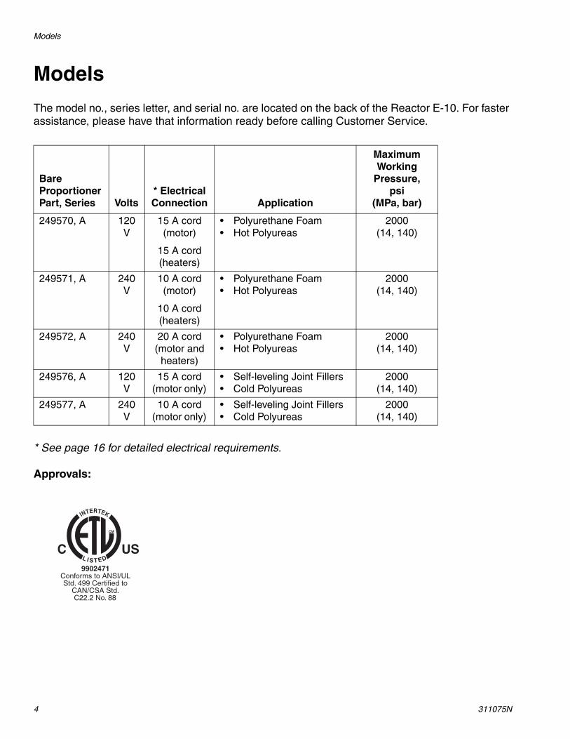
The model no., series letter, and serial no. are located on the back of the Reactor E-10. For faster assistance, please have that information ready before calling Customer Service.
* See page 16 for detailed electrical requirements.
Approvals:
Bare Proportioner Part, Series Volts
* Electrical Connection Application
Maximum Working
Pressure,psi
(MPa, bar)
249570, A 120 V
15 A cord (motor)
15 A cord (heaters)
• Polyurethane Foam• Hot Polyureas
2000 (14, 140)
249571, A 240 V
10 A cord (motor)
10 A cord (heaters)
• Polyurethane Foam• Hot Polyureas
2000 (14, 140)
249572, A 240 V
20 A cord (motor and
heaters)
• Polyurethane Foam• Hot Polyureas
2000 (14, 140)
249576, A 120 V
15 A cord (motor only)
• Self-leveling Joint Fillers• Cold Polyureas
2000 (14, 140)
249577, A 240 V
10 A cord (motor only)
• Self-leveling Joint Fillers• Cold Polyureas
2000 (14, 140)
Warnings
311075N 5
Warnings
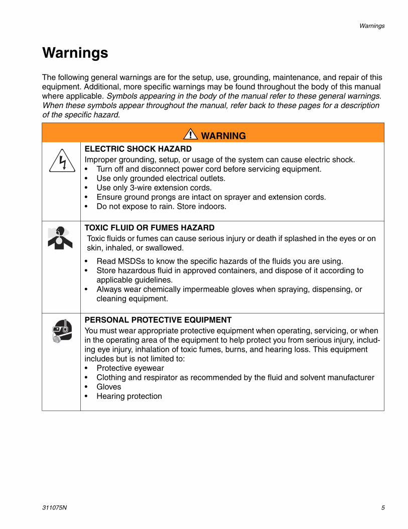
The following general warnings are for the setup, use, grounding, maintenance, and repair of this equipment. Additional, more specific warnings may be found throughout the body of this manual where applicable. Symbols appearing in the body of the manual refer to these general warnings. When these symbols appear throughout the manual, refer back to these pages for a description of the specific hazard.
WARNINGELECTRIC SHOCK HAZARD Improper grounding, setup, or usage of the system can cause electric shock.• Turn off and disconnect power cord before servicing equipment.• Use only grounded electrical outlets.• Use only 3-wire extension cords.• Ensure ground prongs are intact on sprayer and extension cords.• Do not expose to rain. Store indoors.
TOXIC FLUID OR FUMES HAZARD Toxic fluids or fumes can cause serious injury or death if splashed in the eyes or on skin, inhaled, or swallowed.
• Read MSDSs to know the specific hazards of the fluids you are using.• Store hazardous fluid in approved containers, and dispose of it according to
applicable guidelines.• Always wear chemically impermeable gloves when spraying, dispensing, or
cleaning equipment.
PERSONAL PROTECTIVE EQUIPMENT You must wear appropriate protective equipment when operating, servicing, or when in the operating area of the equipment to help protect you from serious injury, includ-ing eye injury, inhalation of toxic fumes, burns, and hearing loss. This equipment includes but is not limited to:• Protective eyewear • Clothing and respirator as recommended by the fluid and solvent manufacturer• Gloves• Hearing protection

Warnings
6 311075N
SKIN INJECTION HAZARD High-pressure fluid from gun, hose leaks, or ruptured components will pierce skin. This may look like just a cut, but it is a serious injury that can result in amputation. Get immediate surgical treatment.• Engage trigger lock when not spraying.• Do not point gun at anyone or at any part of the body.• Do not put your hand over the spray tip.• Do not stop or deflect leaks with your hand, body, glove, or rag.• Follow the Pressure Relief Procedure when you stop spraying and before
cleaning, checking, or servicing equipment. • Tighten all fluid connections before operating the equipment.• Check hoses and couplings daily. Replace worn or damaged parts immediately.
FIRE AND EXPLOSION HAZARD Flammable fumes, such as solvent and paint fumes, in work area can ignite or explode. To help prevent fire and explosion:• Use equipment only in well ventilated area.• Eliminate all ignition sources; such as pilot lights, cigarettes, portable electric
lamps, and plastic drop cloths (potential static arc). • Keep work area free of debris, including solvent, rags and gasoline.• Do not plug or unplug power cords, or turn power or light switches on or off when
flammable fumes are present.• Ground all equipment in work area. See Grounding instructions.• Use only grounded hoses.• Hold gun firmly to side of grounded pail when triggering into pail.• If there is static sparking or you feel a shock, stop operation immediately. Do
not use equipment until you identify and correct the problem.• Keep a fire extinguisher in the work area.
THERMAL EXPANSION HAZARD Fluids subjected to heat in confined spaces, including hoses, can create a rapid rise in pressure due to the thermal expansion. Over-pressurization can result in equipment rupture and serious injury.
• Open a valve to relieve the fluid expansion during heating.• Replace hoses proactively at regular intervals based on your operating condi-
tions.
PRESSURIZED ALUMINUM PARTS HAZARD Do not use 1,1,1-trichloroethane, methylene chloride, other halogenated hydrocar-bon solvents or fluids containing such solvents in pressurized aluminum equipment. Such use can cause serious chemical reaction and equipment rupture, and result in death, serious injury, and property damage.
WARNING
Warnings
311075N 7
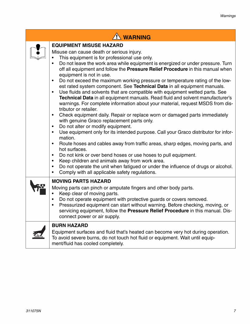
EQUIPMENT MISUSE HAZARD Misuse can cause death or serious injury.• This equipment is for professional use only.• Do not leave the work area while equipment is energized or under pressure. Turn
off all equipment and follow the Pressure Relief Procedure in this manual when equipment is not in use.
• Do not exceed the maximum working pressure or temperature rating of the low-est rated system component. See Technical Data in all equipment manuals.
• Use fluids and solvents that are compatible with equipment wetted parts. See Technical Data in all equipment manuals. Read fluid and solvent manufacturer’s warnings. For complete information about your material, request MSDS from dis-tributor or retailer.
• Check equipment daily. Repair or replace worn or damaged parts immediately with genuine Graco replacement parts only.
• Do not alter or modify equipment.• Use equipment only for its intended purpose. Call your Graco distributor for infor-
mation.• Route hoses and cables away from traffic areas, sharp edges, moving parts, and
hot surfaces.• Do not kink or over bend hoses or use hoses to pull equipment.• Keep children and animals away from work area.• Do not operate the unit when fatigued or under the influence of drugs or alcohol.• Comply with all applicable safety regulations.
MOVING PARTS HAZARD Moving parts can pinch or amputate fingers and other body parts.• Keep clear of moving parts.• Do not operate equipment with protective guards or covers removed.• Pressurized equipment can start without warning. Before checking, moving, or
servicing equipment, follow the Pressure Relief Procedure in this manual. Dis-connect power or air supply.
BURN HAZARD Equipment surfaces and fluid that’s heated can become very hot during operation. To avoid severe burns, do not touch hot fluid or equipment. Wait until equip-ment/fluid has cooled completely.
WARNING

Overview
8 311075N
OverviewThe Reactor E-10 is a portable, electric-pow-ered, 1:1 mix ratio proportioner, for use with a wide variety of coatings, foams, sealants, and adhesives. Materials must be self-leveling and pourable, and may be applied with impinge-ment mix spray guns, disposable mixer guns, or flush-type mix manifolds.
Reactor E-10 is gravity-fed from 7 gal. (26.5 liter) supply tanks mounted on the unit. The tanks are translucent to allow monitoring of fluid level.
Severe duty, positive displacement reciprocat-ing piston pumps meter fluid flow to the gun for mixing and applying. When set to recirculation mode, Reactor E-10 will circulate fluids back to the supply tanks.
Heated models include separate thermostati-cally controlled heaters for each fluid, and an insulated hose bundle with circulation return hoses. This allows the hoses and gun to be preheated to the desired temperature before spraying. Digital displays show the tempera-tures of the two fluids.
An electronic processor controls the motor, monitors fluid pressures, and alerts the opera-tor if errors occur. See STATUS Indicator, page 13, for further information.
Reactor E-10 has two recirculation speeds, slow and fast, and an adjustable pressure out-put.
Slow Recirculation
• Slow circulation results in a higher temper-ature transfer in the heater, so hoses and gun heat up quicker.
• Good for touchup or low flow spraying, up to moderate temperature.
• Not used to circulate full tanks up to tem-perature.
• Use with 245 fa blowing agent foams, to minimize heat returned to tank and reduce frothing.
Fast Recirculation
• Use to support higher flow rates or higher temperatures by preheating the tanks.
• Agitates fluid within tanks, to avoid heating only the fluid at the top of the tank.
• Use for flushing.
Pressure Adjust
Automatically maintains selected pressure out-put for dispensing or spraying.

Isocyanate Hazard
311075N 9
Isocyanate Hazard
Foam Self-ignition
Moisture Sensitivity of IsocyanatesIsocyanates (ISO) are catalysts used in two component foam and polyurea coatings. ISO will react with moisture (such as humidity) to
form small, hard, abrasive crystals, which become suspended in the fluid. Eventually a film will form on the surface and the ISO will begin to gel, increasing in viscosity. If used, this partially cured ISO will reduce perfor-mance and the life of all wetted parts.
To prevent exposing ISO to moisture:
• Always use a sealed container with a desic-cant dryer in the vent, or a nitrogen atmo-sphere. Never store ISO in an open container.
• Keep the felt washers in the pump wet-cups saturated with Graco ISO pump oil, Part No. 217374. The lubricant creates a barrier between the ISO and the atmosphere.
• Use moisture-proof hoses specifically designed for ISO, such as those supplied with your system (see page 63).
• Never use reclaimed solvents, which may contain moisture. Always keep solvent con-tainers closed when not in use.
• Never use solvent on one side if it has been contaminated from the other side.
• Always park pumps when you shutdown, see page 27.
• Always lubricate threaded parts with Part No. 217374 ISO pump oil or grease when reassembling.
Spraying materials containing isocyanates creates potentially harmful mists, vapors, and atomized particulates.
Read material manufacturer’s warnings and material MSDS to know specific hazards and precautions related to isocyanates.
Prevent inhalation of isocyanate mists, vapors, and atomized particulates by provid-ing sufficient ventilation in the work area. If sufficient ventilation is not available, a sup-plied-air respirator is required for everyone in the work area.
To prevent contact with isocyanates, appro-priate personal protective equipment, includ-ing chemically impermeable gloves, boots, aprons, and goggles, is also required for everyone in the work area.
Some materials may become self-igniting if applied too thickly. Read material manufac-turer’s warnings and material MSDS.
The amount of film formation and rate of crystallization varies depending on the blend of ISO, the humidity, and the tem-perature.

Keep Components A and B Separate
10 311075N
Keep Components A and B Separate
Changing Materials• When changing materials, flush the equip-
ment multiple times to ensure it is thor-oughly clean.
• Always clean the fluid inlet strainers after flushing, see page 28.
• Check with your material manufacturer for chemical compatibility.
• Most materials use ISO on the A side, but some use ISO on the B side.
• Epoxies often have amines on the B (hard-ener) side. Polyureas often have amines on the B (resin) side.
NOTICETo prevent cross-contamination of the equip-ment’s wetted parts, never interchange com-ponent A (isocyanate) and component B (resin) parts.
Component Identification
311075N 11
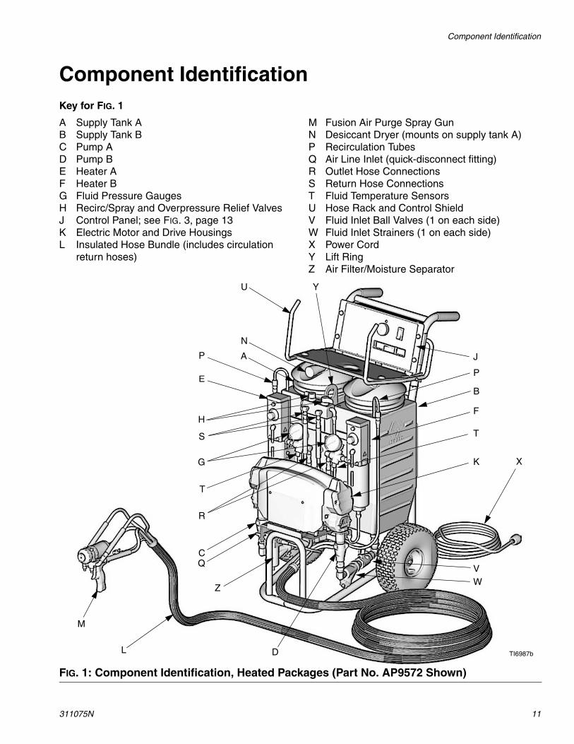
Component IdentificationKey for FIG. 1
A Supply Tank AB Supply Tank BC Pump AD Pump BE Heater AF Heater BG Fluid Pressure GaugesH Recirc/Spray and Overpressure Relief ValvesJ Control Panel; see FIG. 3, page 13K Electric Motor and Drive HousingsL Insulated Hose Bundle (includes circulation
return hoses)
M Fusion Air Purge Spray GunN Desiccant Dryer (mounts on supply tank A)P Recirculation TubesQ Air Line Inlet (quick-disconnect fitting)R Outlet Hose ConnectionsS Return Hose ConnectionsT Fluid Temperature SensorsU Hose Rack and Control ShieldV Fluid Inlet Ball Valves (1 on each side)W Fluid Inlet Strainers (1 on each side)X Power CordY Lift RingZ Air Filter/Moisture Separator
FIG. 1: Component Identification, Heated Packages (Part No. AP9572 Shown)
A
N
B
C
D
E
F
G
H
J
K
L
M
TI6987b
P
P
R
S T
T
U
VW
X
Y
Q
Z

Component Identification
12 311075N
Key for FIG. 2
A Supply Tank AB Supply Tank BC Pump AD Pump BG Fluid Pressure GaugesH Recirc/Spray and Overpressure Relief ValvesJ Control Panel; see FIG. 3, page 13K Electric Motor and Drive HousingsL Hose BundleM 2K Ultra-Lite Spray Gun, with disposable static
mixer
N Desiccant Dryer (mounts on supply tank A)P Recirculation TubesQ Air Line Inlet (quick-disconnect fitting)R Outlet Hose ConnectionsU Hose Rack and Control ShieldV Fluid Inlet Ball Valves (1 on each side)W Fluid Inlet Strainers (1 on each side)X Power CordY Lift RingZ Air Filter/Moisture Separator
FIG. 2: Component Identification, Nonheated Packages (Part No. 249808 Shown)
TI6989b
A
N
B
C
D
G
H
J
K
L
M
PP
R
U
VW
X
Y
Q
Z
Controls and Indicators
311075N 13
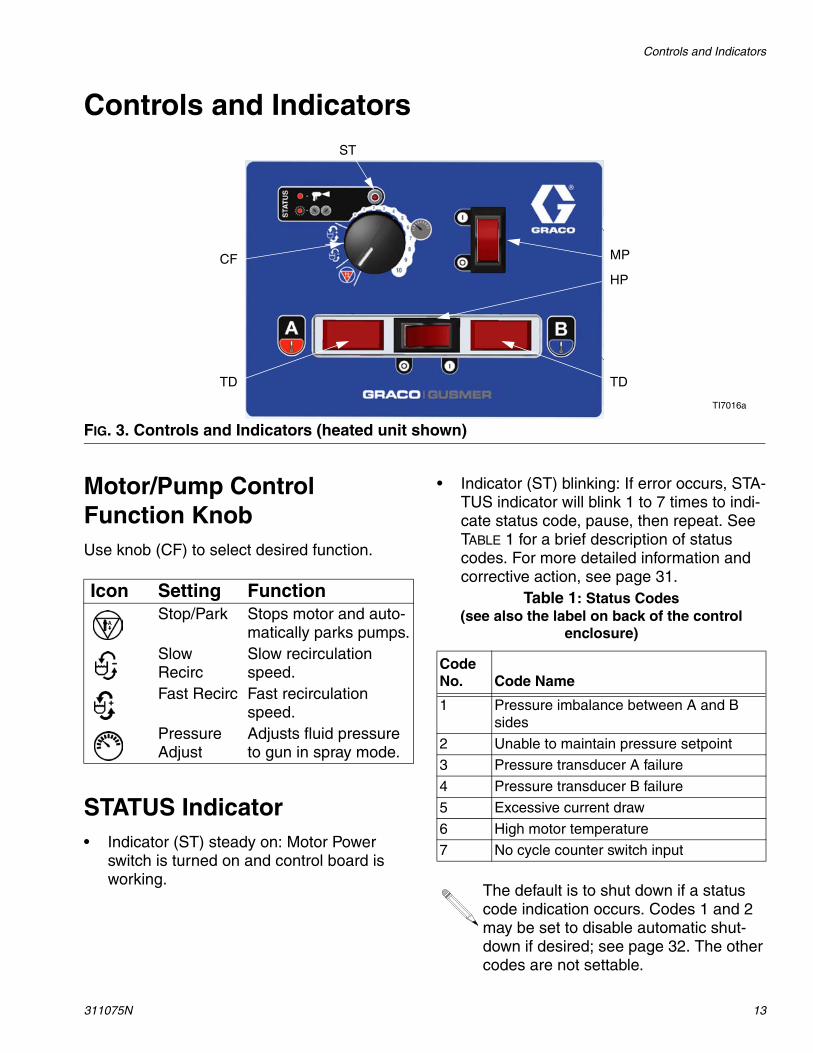
Controls and Indicators
Motor/Pump Control Function KnobUse knob (CF) to select desired function.
STATUS Indicator• Indicator (ST) steady on: Motor Power
switch is turned on and control board is working.
• Indicator (ST) blinking: If error occurs, STA-TUS indicator will blink 1 to 7 times to indi-cate status code, pause, then repeat. See TABLE 1 for a brief description of status codes. For more detailed information and corrective action, see page 31.
FIG. 3. Controls and Indicators (heated unit shown)
MPCF
ST
HP
TD TD
TI7016a
Icon Setting FunctionStop/Park Stops motor and auto-
matically parks pumps.Slow Recirc
Slow recirculation speed.
Fast Recirc Fast recirculation speed.
Pressure Adjust
Adjusts fluid pressure to gun in spray mode.
Table 1: Status Codes(see also the label on back of the control
enclosure)
Code No. Code Name
1 Pressure imbalance between A and B sides
2 Unable to maintain pressure setpoint
3 Pressure transducer A failure
4 Pressure transducer B failure
5 Excessive current draw
6 High motor temperature
7 No cycle counter switch input
The default is to shut down if a status code indication occurs. Codes 1 and 2 may be set to disable automatic shut-down if desired; see page 32. The other codes are not settable.

Controls and Indicators
14 311075N
Motor Power Switch/Circuit BreakerSwitch (MP) turns power on to control board and function knob. The switch includes a 20 A circuit breaker.
Heater Power Switch/Circuit BreakerSee FIG. 3. Switch (HP) turns power on to heater thermostats. The switch includes a 20 A circuit breaker. Present on heated units only.
Heater Temperature ControlsSee FIG. 4. Control knobs (HC) set tempera-ture of component A and B heaters. Indicator lights (HL) turn on when thermostats are heat-ing, and off when heater reaches setpoint. Present on heated units only.
Fluid Temperature Sensors and DisplaysSee FIG. 3. Fluid temperature sensors (T) monitor actual temperature of component A and B fluid going to spray gun. Temperatures are then displayed (TD). Present on heated units only.
Unit is shipped set to °F. To change to °C, see page 43.
FIG. 4. Heater Temperature Controls
HC
HCHL
HL
TI6984b
E
F
T
T

Setup
311075N 15
Setup
Connect Reactor E-10 to the correct power source for your model. See TABLE 2. Models with two power cords must be connected to two separate, dedicated circuits. See FIG. 5.
Some models include cord adapters (55, 56) for use outside North America. Connect the appropriate adapter to the unit’s power cord before connecting to your power source.
The equipment must be grounded. Grounding reduces the risk of static and electric shock by providing an escape wire for the electrical cur-rent due to static build up or in the event of a short circuit.
1. Locate Reactor E-10
a. Locate Reactor E-10 on a level surface.
b. Do not expose Reactor E-10 to rain.
2. Electrical requirements
Improper wiring may cause electric shock or other serious injury if work is not performed properly. Have a qualified electrician perform any electrical work. Be sure your installation complies with all National, State and Local safety and fire codes.
3. Ground system
a. Reactor E-10: grounded through power cord.
b. Generator (if used): follow your local code. Start and stop gener-ator with power cord(s) discon-nected.
c. Spray gun: grounded through the supplied fluid hoses, connected to a properly grounded Reactor E-10. Do not operate without at least one grounded fluid hose.
d. Object being sprayed: follow your local code.
e. Solvent pails used when flushing: follow your local code. Use only metal pails, which are conduc-tive, placed on a grounded sur-face. Do not place pail on a nonconductive surface, such as paper, plastic, or cardboard, which interrupts grounding conti-nuity.
f. To maintain grounding continuity when flushing or relieving pres-sure, hold a metal part of spray gun firmly to the side of a grounded metal pail, then trigger gun.
Setup
16 311075N
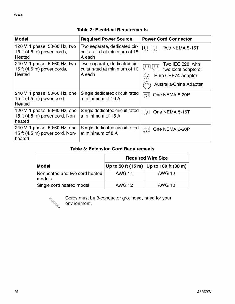
Table 2: Electrical Requirements
Model Required Power Source Power Cord Connector
120 V, 1 phase, 50/60 Hz, two 15 ft (4.5 m) power cords, Heated
Two separate, dedicated cir-cuits rated at minimum of 15 A each
240 V, 1 phase, 50/60 Hz, two 15 ft (4.5 m) power cords, Heated
Two separate, dedicated cir-cuits rated at minimum of 10 A each
240 V, 1 phase, 50/60 Hz, one 15 ft (4.5 m) power cord, Heated
Single dedicated circuit rated at minimum of 16 A
120 V, 1 phase, 50/60 Hz, one 15 ft (4.5 m) power cord, Non-heated
Single dedicated circuit rated at minimum of 15 A
240 V, 1 phase, 50/60 Hz, one 15 ft (4.5 m) power cord, Non-heated
Single dedicated circuit rated at minimum of 8 A
Two NEMA 5-15T
Two IEC 320, with two local adapters:
Euro CEE74 Adapter
Australia/China Adapter
One NEMA 6-20P
One NEMA 5-15T
One NEMA 6-20P
Table 3: Extension Cord Requirements
Model
Required Wire Size
Up to 50 ft (15 m) Up to 100 ft (30 m)
Nonheated and two cord heated models
AWG 14 AWG 12
Single cord heated model AWG 12 AWG 10
Cords must be 3-conductor grounded, rated for your environment.

Setup
311075N 17
FIG. 5. Use Two Separate Circuits for Two Cord Models
1Ensure no other high amp loads are connected while running Reactor E-10.
To verify separate circuits, plug in Reactor E-10 or a worklight and cycle breakers on and off.
1
2
To avoid electric shock, always unplug both cords before servicing Reactor E-10.
1Heater Power
Motor Power TI7061a
2
4. Connect fluid hoses
Connect fluid supply hoses to outlet hose connections (R, FIG. 6). Red hoses for component A (ISO), blue for compo-nent B (RES). Fittings are sized to pre-vent connection errors. Connect other end of hoses to A and B inputs of gun.
Heated units only: connect recirculation hoses from gun recirculation ports to connections (S).
5. Connect gun air hose
Connect gun air hose to the gun air input and to the air filter outlet (Z). If you are using more than one hose bundle, join the air hoses with the nipple (305) provided with the hose bundle.
On heated units with Fusion guns, con-nect the supplied ball valve and quick-disconnect coupler to the gun air hose, then connect the coupler to the gun air fitting.
6. Connect main air supply
Connect the main air supply to the quick disconnect fitting (Q) on the unit. Air supply hose must be at least 5/16 in. (8 mm) ID up to 50 ft (15 m) or 3/8 in. (10 mm) ID up to 100 ft (30 m).
Air Filter/Moisture Separator (Z) is equipped with an automatic moisture drain.
7. Flush before first use
The Reactor E-10 is tested with a plasti-cizer oil at the factory. Flush out the oil with a compatible solvent before spray-ing. See page 29.

Setup
18 311075N
FIG. 6. Hose Connections
TI6988b
TI6990b
Heated Units
Nonheated
R
S
R
Q
Z
ZQ
AIR
AIR
B (RES)
A (ISO)
A (ISO)B (RES)

Setup
311075N 19
8. Fill wet-cups
Keep the felt washers in the pump wet-cups saturated with Graco ISO pump oil, Part No. 217374. The lubricant creates a barrier between the ISO and the atmosphere.
Fill wet-cups through slotsin plate, or loosen screws
and swing plate aside.TI6985a
Pump rod and connecting rod move during operation. Moving parts can cause serious injury such as pinching or amputation. Keep hands and fingers away from wet-cup during
operation. Shut off Motor Power
before filling wet-cup.
9. Fill fluid tanks
NOTICETo prevent cross-contamination of fluids and equipment parts, never interchange compo-nent A (isocyanate) and component B (resin) parts or containers.
Have at least two 5 gal. (19 liter) pails to transfer fluid from drums to supply tanks. Label one pail “A” and the other “B”, using the red and blue labels provided. Always doublecheck which material you have before pouring it in the supply tanks. Pouring is eas-ier if pails are not filled to the top.
Open only one supply tank at a time, to avoid splashing material from one tank into the other when filling.
Using a drill and mixing blade, mix filled or separated materials in the pail before add-ing to the tanks. Material left in the tanks overnight may need to be remixed in the tanks.
Setup
20 311075N
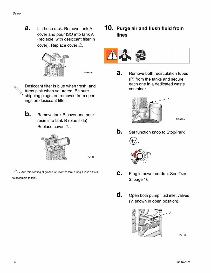
a. Lift hose rack. Remove tank A cover and pour ISO into tank A (red side, with desiccant filter in
cover). Replace cover .
Desiccant filter is blue when fresh, and turns pink when saturated. Be sure shipping plugs are removed from open-ings on desiccant filter.
b. Remove tank B cover and pour resin into tank B (blue side).
Replace cover .
. Add thin coating of grease lubricant to tank o-ring if lid is difficult
to assemble to tank.
1
TI7017a
1
TI7018a
1
10. Purge air and flush fluid from lines
a. Remove both recirculation tubes (P) from the tanks and secure each one in a dedicated waste container.
b. Set function knob to Stop/Park
.
c. Plug in power cord(s). See TABLE 2, page 16.
d. Open both pump fluid inlet valves (V, shown in open position).
TI7022a
P
V
TI7019a

Setup
311075N 21
e. Turn on Motor Power.
f. Set Recirc/Spray valves to Recirc.
g. Set function knob to Slow Recirc
or Fast Recirc .
OR
h. When clean fluids exit both recir-culation tubes (P), set function
knob to Stop/Park .
i. Replace recirculation tubes in supply tanks.
j. On nonheated units, purge the hoses through the gun without a static mixer installed.
For heated units, continue with Startup of Heated Units, page 22.
Nonheated units are ready to spray/dis-pense. Go to Spraying/Dispensing, page 25.
Startup of Heated Units
22 311075N
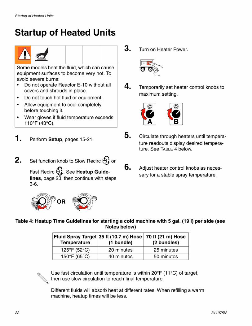
Startup of Heated Units
Some models heat the fluid, which can cause equipment surfaces to become very hot. To avoid severe burns: • Do not operate Reactor E-10 without all
covers and shrouds in place.• Do not touch hot fluid or equipment.• Allow equipment to cool completely
before touching it.• Wear gloves if fluid temperature exceeds
110°F (43°C).
1. Perform Setup, pages 15-21.
2. Set function knob to Slow Recirc or
Fast Recirc . See Heatup Guide-lines, page 23, then continue with steps 3-6.
OR
3. Turn on Heater Power.
4. Temporarily set heater control knobs to maximum setting.
5. Circulate through heaters until tempera-ture readouts display desired tempera-ture. See TABLE 4 below.
6. Adjust heater control knobs as neces-sary for a stable spray temperature.
Table 4: Heatup Time Guidelines for starting a cold machine with 5 gal. (19 l) per side (see Notes below)
Fluid Spray Target Temperature
35 ft (10.7 m) Hose (1 bundle)
70 ft (21 m) Hose (2 bundles)
125°F (52°C) 20 minutes 25 minutes150°F (65°C) 40 minutes 50 minutes
Use fast circulation until temperature is within 20°F (11°C) of target, then use slow circulation to reach final temperature.
Different fluids will absorb heat at different rates. When refilling a warm machine, heatup times will be less.
Startup of Heated Units
311075N 23
Heatup Guidelines
Slow Recirculation
• Slow Recirc results in a higher temperature transfer in the heater, so hoses and gun heat up quicker.
• Good for touchup or low flow spraying, up to moderate temperature.
• Not used to circulate full tanks up to tem-perature.
• Use with 245 fa blowing agent foams, to minimize heat returned to tank and reduce frothing.
Fast Recirculation
• Fast Recirc keeps heaters on fulltime to bring fluid tanks up to temperature. The higher your usage rate, the more heat needed in the tanks before spraying. • For normal usage rates: Use Fast
Recirc to get tanks to approximately 50°F (28°C) below desired spray tem-perature, then use Slow Recirc to raise hose and gun to desired temperature.
• For higher flow rates or continuous spraying: Use Fast Recirc to bring tem-perature of tanks to approximately 20°F (11°C) below desired spray tempera-ture, then use Slow Recirc to raise hose and gun to desired temperature.
• Volume in tanks: Use only what you need. For example, 2.5 gal. (10 l) in each tank will heat up almost twice as fast as 5 gal. (20 l).
• Mixes fluid within tanks, to avoid heating only the fluid at the top of the tank.
• Use for flushing.
Heat Management Tips• Heaters perform better with lower flow rates
or smaller mix modules.
• Triggering the gun for short periods helps maintain efficient heat transfer, keeping material at the desired temperature. Trig-gering the gun for a long period does not allow enough heating time, and cold mate-rial will enter the hose.
• If temperature displays fall below accept-able limits, set function knob to Slow Recirc
and circulate again to bring tempera-tures back up.
• Each 35 ft (10.7 m) hose bundle adds about 5 minutes to heatup time, with most materials. Water-based materials take lon-ger to heat up. Maximum recommended hose length is 105 ft (32 m).
• Use Fast Recirc until tanks are warm to
the touch, then use Slow Recirc until displays read desired temperature.
• For a quicker start, do initial heatup circula-tion with the tanks 1/4 to 1/3 filled, then add more material.
The fluids must be circulated from the pumps through the heaters, hoses, and back to the tanks to ensure warm fluids are supplied to the gun.
Startup of Heated Units
24 311075N
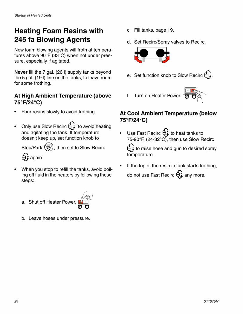
Heating Foam Resins with 245 fa Blowing AgentsNew foam blowing agents will froth at tempera-tures above 90°F (33°C) when not under pres-sure, especially if agitated.
Never fill the 7 gal. (26 l) supply tanks beyond the 5 gal. (19 l) line on the tanks, to leave room for some frothing.
At High Ambient Temperature (above 75°F/24°C)
• Pour resins slowly to avoid frothing.
• Only use Slow Recirc , to avoid heating and agitating the tank. If temperature doesn’t keep up, set function knob to
Stop/Park , then set to Slow Recirc
again.
• When you stop to refill the tanks, avoid boil-ing off fluid in the heaters by following these steps:
a. Shut off Heater Power.
b. Leave hoses under pressure.
c. Fill tanks, page 19.
d. Set Recirc/Spray valves to Recirc.
e. Set function knob to Slow Recirc .
f. Turn on Heater Power.
At Cool Ambient Temperature (below 75°F/24°C)
• Use Fast Recirc to heat tanks to 75-90°F. (24-32°C), then use Slow Recirc
to raise hose and gun to desired spray temperature.
• If the top of the resin in tank starts frothing,
do not use Fast Recirc any more.

Spraying/Dispensing
311075N 25
Spraying/Dispensing
Air is supplied to spray gun with gun piston safety lock or trigger safety lock engaged and gun fluid manifold valves A and B closed (if present).
1. Set function knob to Stop/Park .
2. Set Recirc/Spray valves to Spray.
3. Turn function knob to Pressure Adjust
. Keep turning to the right until fluid
pressure gauges show desired pres-sure.
TI7069aFusion 2K Ultra-Lite
4. Check fluid pressure gauges to ensure proper pressure balance. If imbalanced, reduce pressure of higher component by slightly turning Recirc/Spray valve for that component toward Recirc, until gauges show balanced pressures. The pressure imbalance alarm (Status Code 1) is inactive for 10 sec after entering spray pressure mode, to allow time to balance pressures.
Watch gauges for 10 sec to be sure pres-sure holds on both sides and pumps are not moving.
5. Open gun fluid manifold valves A and B (impingement mix guns only).
On impingement guns, never open fluid manifold valves or trigger gun if pressures are imbalanced.
In this example, B side pressure is higher, so use the B side valve to balance pressures.

Pause (Heated Units)
26 311075N
Pause (Heated Units)
Refilling TanksMaterial can be added to the tanks at any time. See page 19.
6. Disengage piston safety lock or trigger safety lock.
7. Test spray onto cardboard or plastic sheet. Verify that material fully cures in the required length of time, and is the correct color. Adjust pressure and tem-perature to get desired results. Equip-ment is ready to spray.
To bring the hose and gun back to spray temperature after a brief break, use the fol-lowing procedure.
1. Engage piston safety lock or trigger safety lock.
2. Set function knob to Slow Recirc .
TI7070aFusion 2K Ultra-Lite
TI7069aFusion 2K Ultra-Lite
3. Set Recirc/Spray valves to Recirc until temperature readouts come back up.
4. If you stop spraying for more than 2 min-utes when using an impingement mix gun, close gun fluid valves A and B. Doing this will keep the internal parts of the gun cleaner and prevent crossover.
If you are operating at high temperatures or flow rates, follow instructions under Pause (Heated Units) to bring tanks up to temperature.
NOTICETo prevent cross-contamination of fluids and equipment parts, never interchange component A (isocyanate) and component B (resin) parts or containers.
Have at least two 5 gal. (19 liter) pails to transfer fluid from drums to supply tanks. Label one pail “A” and the other “B”, using the red and blue labels provided. Always doublecheck which material you have before pouring it in the supply tanks. Pouring is easier if pails are not filled to the top.
Open only one supply tank at a time, to avoid splashing material from one tank into the other when filling.
Pressure Relief Procedure
311075N 27
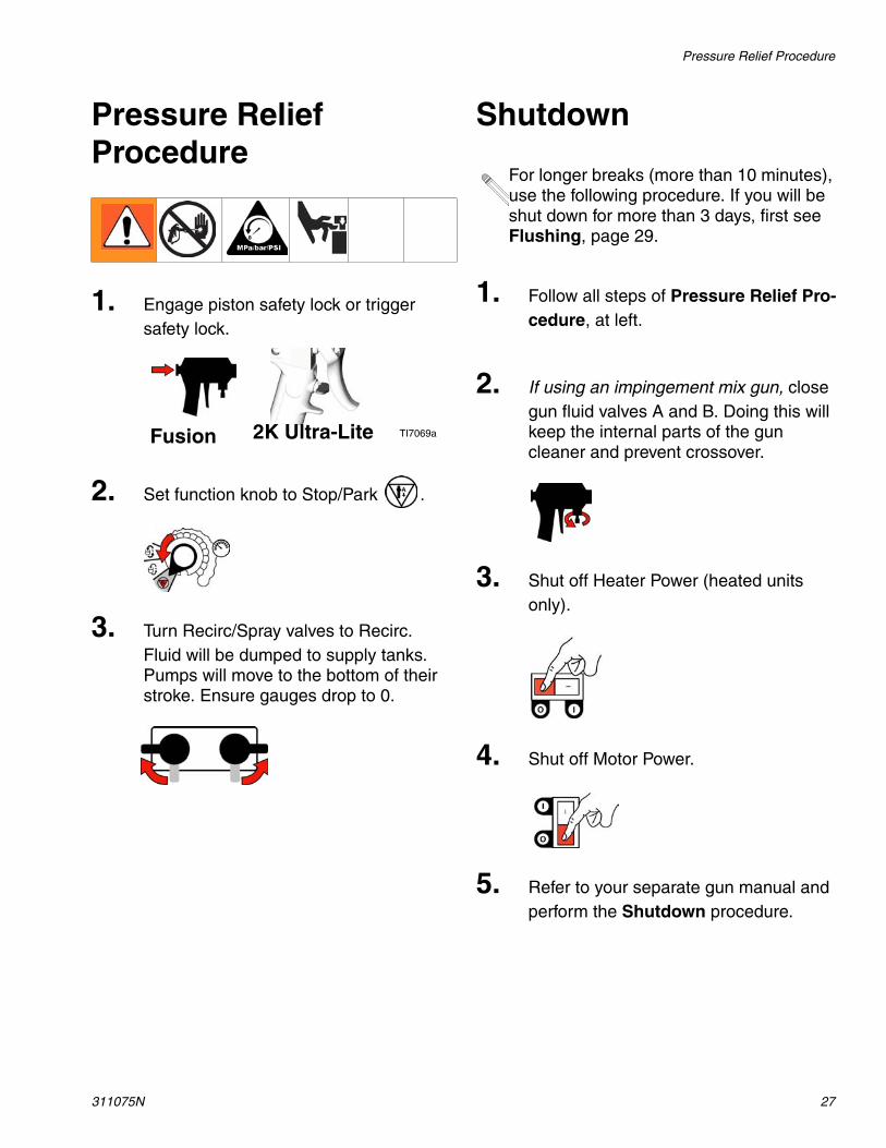
Pressure Relief Procedure
Shutdown
1. Engage piston safety lock or trigger safety lock.
2. Set function knob to Stop/Park .
3. Turn Recirc/Spray valves to Recirc. Fluid will be dumped to supply tanks. Pumps will move to the bottom of their stroke. Ensure gauges drop to 0.
TI7069aFusion 2K Ultra-Lite
For longer breaks (more than 10 minutes), use the following procedure. If you will be shut down for more than 3 days, first see Flushing, page 29.
1. Follow all steps of Pressure Relief Pro-cedure, at left.
2. If using an impingement mix gun, close gun fluid valves A and B. Doing this will keep the internal parts of the gun cleaner and prevent crossover.
3. Shut off Heater Power (heated units only).
4. Shut off Motor Power.
5. Refer to your separate gun manual and perform the Shutdown procedure.

Maintenance
28 311075N
Maintenance• Check pump wet-cups fluid level daily, page
19.
• Do not overtighten packing nut/wet-cup. Throat u-cup is not adjustable.
• Keep component A from exposure to mois-ture in atmosphere, to prevent crystalliza-tion.
• Wipe supply tank lid o-ring and inner rim daily to prevent ISO crystallization. Keep film of grease on o-ring and inside of lid.
• Check desiccant filter weekly. Filter is blue when fresh, and turns pink when saturated.
• Remove plug (X) and clean fluid inlet strainer (51a) as needed. Always clean the fluid inlet strainers after flushing.
• Generally, flush if you will shutdown for more than three days. Flush more often if material is moisture sensitive and humidity is high in the storage area, or if material may separate or settle out over time.
• If using an impingement mix gun, close gun fluid valves A and B when not spraying. Doing this will keep the internal parts of the gun cleaner and prevent crossover. Clean gun mix chamber ports and check valve screens regularly. See gun manual.
• If using an Fusion Air Purge impingement mix gun, always grease the gun after use until purge air carries grease mist out the front of the gun. Use Part No. 117773 Grease. See gun manual 309550.
X
51a
TI7021a

Flushing
311075N 29
Flushing
• Generally, flush if you will be shut down for more than 3 days. Flush more often if mate-rial is moisture sensitive and humidity is high in the storage area, or if material may separate or settle out over time.
• Flush out old fluid with new fluid, or flush out old fluid with a compatible solvent before introducing new fluid.
• Use the lowest possible pressure when flushing.
• Always leave some type of fluid in system. Do not use water.
• For long term storage, flush out the solvent with a storage fluid such as Bayer Mesa-moll plasticizer or, at minimum, clean motor oil.
Flush equipment only in a well-ventilated area. Do not spray flammable fluids. Do not turn on heaters while flushing with flammable solvents.
1. Engage piston safety lock or trigger safety lock. Close fluid valves A and B. Leave air on.
TI7069aFusion 2K Ultra-Lite
2. Set function knob to Stop/Park .
3. Shut off Heater Power (heated units only). Allow system to cool.
4. Remove recirculation tubes (31) from supply tanks and place in original con-tainers or waste containers.
5. Turn Recirc/Spray valves to Recirc.
6. Set function knob to Fast Recirc . Pump material from supply tanks until no more comes out.
TI7022a
31

Flushing
30 311075N
7. Set function knob to Stop/Park .
8. Wipe out any remaining material from the supply tanks. Fill each supply tank with 1-2 gal. (3.8-7.6 l) of solvent recom-mended by your material manufacturer.
9. Set function knob to Fast Recirc . Pump solvent through system to waste containers.
10. When nearly clear solvent comes from recirculation tubes, set function knob to
Stop/Park . Return recirculation tubes to supply tanks.
11. Set function knob to Fast Recirc . Circulate solvent through system for 10-20 minutes to ensure thorough cleaning.
To flush gun, refer to gun instruction manual.
Purge Gun Hoses (Nonheated Units Only)
Disconnect hoses from gun and secure back into the tanks for thorough cleaning with solvent.
• Turn Recirc/Spray valve A to Spray.
• Open gun into waste container A.
• Set function knob to Slow Recirc until hose is flushed.
• Set function knob to Stop/Park .• Repeat for B side.
12. Set function knob to Stop/Park .
13. Solvent flushing is a two step process. Go back to step 4, drain solvent, and flush again with fresh solvent.
14. Leave unit filled with solvent, plasticizer, clean motor oil, or refill supply tanks with new material and reprime.
Never leave the unit dry unless it has been disassembled and cleaned. If fluid residue dries in the pumps, the ball checks may stick the next time you use the unit.

Troubleshooting
311075N 31
Troubleshooting
Status CodesDetermine the status code by counting the number of times the status indicator (ST) blinks.
Status Code 1: Pressure Imbalance
Unit senses pressure imbalance between com-ponents A and B, and warns or shuts down, depending on settings of DIP switches 1 and 2. To turn off automatic shutdown and/or tighten pressure tolerances for status code 1, see Sta-tus Code 1 and 2 Settings.
1. Check fluid supply of lower pressure com-ponent and refill if necessary.
2. Reduce pressure of higher component by slightly turning Recirc/Spray valve for that component toward Recirc, until gauges show balanced pressures.
3. Check fluid inlet strainers (51a, page 28) and fluid filters at gun.
4. Clean or change restrictor at mixer mani-fold if using disposable mixer gun kit.
Status Code 2: Pressure Deviation from Setpoint
Unit senses pressure deviation from setpoint, and warns or shuts down, depending on set-tings of DIP switches 3 and 4. If equipment cannot maintain enough pressure for a good mix with an impingement mix gun, try using a smaller mix chamber or nozzle.
To turn off automatic shutdown and/or tighten pressure tolerances for status code 2, see Sta-tus Code 1 and 2 Settings.
The unit does not check for pressure imbalance at setpoints less than 250 psi (1.75 MPa, 17.5 bar).
The unit does not check for pressure imbalance for 10 sec after entering pres-sure mode.
ST
TI7016a
Turn Recirc/Spray valve only enough to balance pressure. If turned completely, all pressure will bleed off.
The unit does not check for pressure deviation at setpoint less than 400 psi (2.8 MPa, 28 bar).
In this example, B side pressure is higher, so use the B side valve to balance pressures.
Troubleshooting
32 311075N
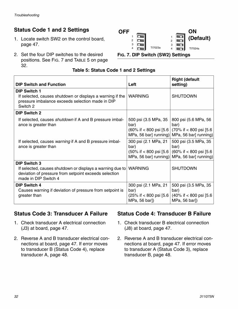
Status Code 1 and 2 Settings
1. Locate switch SW2 on the control board, page 47.
2. Set the four DIP switches to the desired positions. See FIG. 7 and TABLE 5 on page 32.
Status Code 3: Transducer A Failure
1. Check transducer A electrical connection (J3) at board, page 47.
2. Reverse A and B transducer electrical con-nections at board, page 47. If error moves to transducer B (Status Code 4), replace transducer A, page 48.
Status Code 4: Transducer B Failure
1. Check transducer B electrical connection (J8) at board, page 47.
2. Reverse A and B transducer electrical con-nections at board, page 47. If error moves to transducer A (Status Code 3), replace transducer B, page 48.
FIG. 7. DIP Switch (SW2) Settings
TI7023a TI7024a
ON (Default)
OFF12
34
12
34
Table 5: Status Code 1 and 2 Settings
DIP Switch and Function LeftRight (default setting)
DIP Switch 1If selected, causes shutdown or displays a warning if the pressure imbalance exceeds selection made in DIP Switch 2
WARNING SHUTDOWN
DIP Switch 2
If selected, causes shutdown if A and B pressure imbal-ance is greater than
500 psi (3.5 MPa, 35 bar)(60% if < 800 psi [5.6 MPa, 56 bar] running)
800 psi (5.6 MPa, 56 bar)(70% if < 800 psi [5.6 MPa, 56 bar] running)
If selected, causes warning if A and B pressure imbal-ance is greater than
300 psi (2.1 MPa, 21 bar)(50% if < 800 psi [5.6 MPa, 56 bar] running)
500 psi (3.5 MPa, 35 bar)(60% if < 800 psi [5.6 MPa, 56 bar] running)
DIP Switch 3If selected, causes shutdown or displays a warning due to deviation of pressure from setpoint exceeds selection made in DIP Switch 4
WARNING SHUTDOWN
DIP Switch 4Causes warning if deviation of pressure from setpoint is greater than
300 psi (2.1 MPa, 21 bar)(25% if < 800 psi [5.6 MPa, 56 bar])
500 psi (3.5 MPa, 35 bar)(40% if < 800 psi [5.6 MPa, 56 bar])

Troubleshooting
311075N 33
Status Code 5: Excessive Current Draw
Shut off unit and contact distributor before resuming operation.
1. Locked rotor; motor unable to turn. Replace motor, page 51.
2. Short on control board. Replace board, page 46.
3. Worn or hung up motor brush causing arc-ing of brush at commutator. Replace brushes, page 52.
Status Code 6: High Motor Temperature
Motor is running too hot.
1. Motor temperature too high. Reduce pres-sure duty cycle, gun tip size, or move Reac-tor E-10 to a cooler location. Allow 1 hour for cooling.
2. Check fan operation. Clean fan and motor housing.
Status Code 7: No Cycle Counter Switch Input
Have not received input from cycle counter switch for 10 seconds after selecting Recirc mode.
1. Check cycle counter switch connection to board (J10, pins 5, 6), page 47.
2. Check that magnet (224) and cycle counter switch (223) are in place under B side motor end cover (227). Replace if neces-sary.
Troubleshooting
34 311075N
Troubleshooting Chart
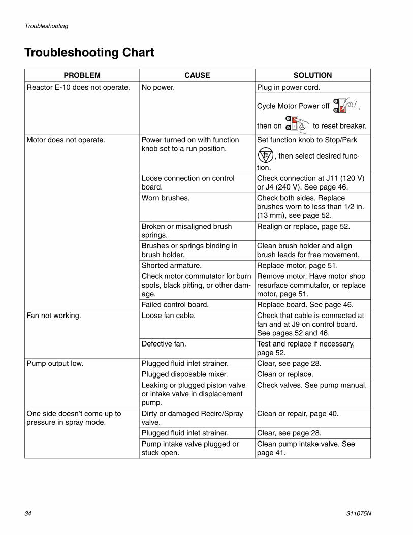
PROBLEM CAUSE SOLUTION
Reactor E-10 does not operate. No power. Plug in power cord.
Cycle Motor Power off ,
then on to reset breaker.
Motor does not operate. Power turned on with function knob set to a run position.
Set function knob to Stop/Park
, then select desired func-
tion.
Loose connection on control board.
Check connection at J11 (120 V) or J4 (240 V). See page 46.
Worn brushes. Check both sides. Replace brushes worn to less than 1/2 in. (13 mm), see page 52.
Broken or misaligned brush springs.
Realign or replace, page 52.
Brushes or springs binding in brush holder.
Clean brush holder and align brush leads for free movement.
Shorted armature. Replace motor, page 51.
Check motor commutator for burn spots, black pitting, or other dam-age.
Remove motor. Have motor shop resurface commutator, or replace motor, page 51.
Failed control board. Replace board. See page 46.
Fan not working. Loose fan cable. Check that cable is connected at fan and at J9 on control board. See pages 52 and 46.
Defective fan. Test and replace if necessary, page 52.
Pump output low. Plugged fluid inlet strainer. Clear, see page 28.
Plugged disposable mixer. Clean or replace.
Leaking or plugged piston valve or intake valve in displacement pump.
Check valves. See pump manual.
One side doesn’t come up to pressure in spray mode.
Dirty or damaged Recirc/Spray valve.
Clean or repair, page 40.
Plugged fluid inlet strainer. Clear, see page 28.
Pump intake valve plugged or stuck open.
Clean pump intake valve. See page 41.
Troubleshooting
311075N 35
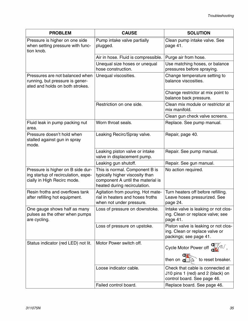
Pressure is higher on one side when setting pressure with func-tion knob.
Pump intake valve partially plugged.
Clean pump intake valve. See page 41.
Air in hose. Fluid is compressible. Purge air from hose.
Unequal size hoses or unequal hose construction.
Use matching hoses, or balance pressures before spraying.
Pressures are not balanced when running, but pressure is gener-ated and holds on both strokes.
Unequal viscosities. Change temperature setting to balance viscosities.
Change restrictor at mix point to balance back pressure.
Restriction on one side. Clean mix module or restrictor at mix manifold.
Clean gun check valve screens.
Fluid leak in pump packing nut area.
Worn throat seals. Replace. See pump manual.
Pressure doesn’t hold when stalled against gun in spray mode.
Leaking Recirc/Spray valve. Repair, page 40.
Leaking piston valve or intake valve in displacement pump.
Repair. See pump manual.
Leaking gun shutoff. Repair. See gun manual.
Pressure is higher on B side dur-ing startup of recirculation, espe-cially in High Recirc mode.
This is normal. Component B is typically higher viscosity than component A until the material is heated during recirculation.
No action required.
Resin froths and overflows tank after refilling hot equipment.
Agitation from pouring. Hot mate-rial in heaters and hoses froths when not under pressure.
Turn heaters off before refilling. Leave hoses pressurized. See page 24.
One gauge shows half as many pulses as the other when pumps are cycling.
Loss of pressure on downstoke. Intake valve is leaking or not clos-ing. Clean or replace valve; see page 41.
Loss of pressure on upstoke. Piston valve is leaking or not clos-ing. Clean or replace valve or packings; see page 41.
Status indicator (red LED) not lit. Motor Power switch off.Cycle Motor Power off ,
then on to reset breaker.
Loose indicator cable. Check that cable is connected at J10 pins 1 (red) and 2 (black) on control board. See page 46.
Failed control board. Replace board. See page 46.
PROBLEM CAUSE SOLUTION

Troubleshooting
36 311075N
A side rich; lack of B side. A side gauge is low. B side restriction downstream of gauge. Check gun check valve screen, mix module, or mix mani-fold restrictor.
B side gauge is low. B side material supply problem. Check B side inlet strainer and pump intake valve.
B side rich; lack of A side. A side gauge is low. A side material supply problem. Check A side inlet strainer and pump intake valve.
B side gauge is low. A side restriction downstream of gauge. Check gun check valve screen, mix module, or mix mani-fold restrictor.
No temperature display (heated units only).
Loose display cables on control board.
Check cable connections to each display, page 46.
Failed control board (displays get power from control board).
Remove access panel. Check if board LED is lighted. If not, replace board, page 46.
Inadequate power to control board.
Check that power supply meets requirements.
Loose power cable. Check cable connections, page 46.
Motor Power switch circuit breaker tripped.
Display is powered from Motor Power circuit breaker. Cycle Motor
Power off , then on
to reset breaker.
Wrong temperature displayed. °F/°C switch in wrong position. Set switch, see page 43.
Temperature displays do not match at ambient temperature.
Displays need calibration. Turn calibration screw on back of displays to correct reading, see page 43.
PROBLEM CAUSE SOLUTION
Troubleshooting
311075N 37
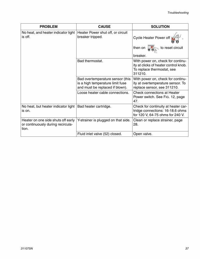
No heat, and heater indicator light is off.
Heater Power shut off, or circuit breaker tripped. Cycle Heater Power off ,
then on to reset circuit
breaker.
Bad thermostat. With power on, check for continu-ity at clicks of heater control knob. To replace thermostat, see 311210.
Bad overtemperature sensor (this is a high temperature limit fuse and must be replaced if blown).
With power on, check for continu-ity at overtemperature sensor. To replace sensor, see 311210.
Loose heater cable connections. Check connections at Heater Power switch. See FIG. 12, page 47.
No heat, but heater indicator light is on.
Bad heater cartridge. Check for continuity at heater car-tridge connections: 16-18.6 ohms for 120 V, 64-75 ohms for 240 V.
Heater on one side shuts off early or continuously during recircula-tion.
Y-strainer is plugged on that side. Clean or replace strainer, page 28.
Fluid inlet valve (52) closed. Open valve.
PROBLEM CAUSE SOLUTION

Troubleshooting
38 311075N
Repair
311075N 39
Repair
Before Beginning Repair Removing Supply Tanks
Repairing this equipment requires access to parts which may cause electric shock or other serious injury if work is not performed properly. Have a qualified electrician connect power and ground to main power switch ter-minals, see page 15. Be sure to shut off all power to the equipment before repairing.
1. Flush if possible, see page 29. If not possi-ble, clean all parts with solvent immediately after removal, to prevent isocyanate from crystallizing due to moisture in the atmo-sphere.
2. Set function knob to Stop/Park .
3. Shut off Motor Power. Disconnect power supply.
4. Shut off Heater Power. Allow equipment to cool before repairing.
5. Relieve pressure, page 27.
Displacement pump repair and parts information is included in manual 311076, which is supplied with your unit.
1. See Before Beginning Repair, page 39. Relieve pressure, page 27.
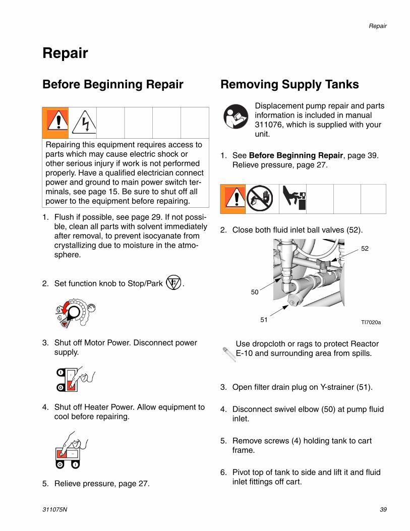
2. Close both fluid inlet ball valves (52).
Use dropcloth or rags to protect Reactor E-10 and surrounding area from spills.
3. Open filter drain plug on Y-strainer (51).
4. Disconnect swivel elbow (50) at pump fluid inlet.
5. Remove screws (4) holding tank to cart frame.
6. Pivot top of tank to side and lift it and fluid inlet fittings off cart.
52
TI7020a51
50
Repair
40 311075N
Recirc/Spray Valves
1. See Before Beginning Repair, page 39. Relieve pressure, page 27.
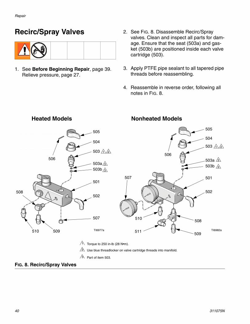
2. See FIG. 8. Disassemble Recirc/Spray valves. Clean and inspect all parts for dam-age. Ensure that the seat (503a) and gas-ket (503b) are positioned inside each valve cartridge (503).
3. Apply PTFE pipe sealant to all tapered pipe threads before reassembling.
4. Reassemble in reverse order, following all notes in FIG. 8.
FIG. 8. Recirc/Spray Valves
1
505
504
503
501
502
507
509510
508
506503a503b
TI6977a TI6982a
Heated Models Nonheated Models
Torque to 250 in-lb (28 N•m).1
2
505
504
503
501
502
509
510
507
506
511
508
503a503b
Use blue threadlocker on valve cartridge threads into manifold.2
Part of item 503.3
3
1 2
33
3

Repair
311075N 41
Displacement Pump To Remove Intake Valve Only
Displacement pump repair and parts information is included in manual 311076, which is supplied with your unit.
Use dropcloth or rags to protect Reactor E-10 and surrounding area from spills.
1. See Before Beginning Repair, page 39. Relieve pressure, page 27.
2. Close both fluid inlet ball valves (52). Open filter drain plug on Y-strainer (51).
52
TI7020a51
If pump is not generating any pressure, the intake ball check may be stuck closed with dried material.
If the pump is not generating pressure on the downstroke, intake ball check may be stuck open.
Either of these conditions can be serviced with the pump in place.
3. Disconnect fluid inlet (C) and swing it aside.
4. Remove intake valve by hitting ears (E) firmly right-to-left with a non-sparking ham-mer. Unscrew from pump. See manual 311076 for repair and parts.
Repair
42 311075N
To Remove Entire Pump Assembly
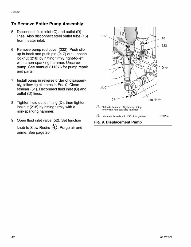
5. Disconnect fluid inlet (C) and outlet (D) lines. Also disconnect steel outlet tube (16) from heater inlet.
6. Remove pump rod cover (222). Push clip up in back and push pin (217) out. Loosen locknut (218) by hitting firmly right-to-left with a non-sparking hammer. Unscrew pump. See manual 311076 for pump repair and parts.
7. Install pump in reverse order of disassem-bly, following all notes in FIG. 9. Clean strainer (51). Reconnect fluid inlet (C) and outlet (D) lines.
8. Tighten fluid outlet fitting (D), then tighten locknut (218) by hitting firmly with a non-sparking hammer.
9. Open fluid inlet valve (52). Set function
knob to Slow Recirc . Purge air and prime. See page 20.
FIG. 9. Displacement Pump
C
D
16217
1
Flat side faces up. Tighten by hitting firmly with non-sparking hammer.
1
Lubricate threads with ISO oil or grease.2
2
2
2
TI7025a
218
222
51
E
Repair
311075N 43
Control Module
Change Display Temperature Units (°F/°C)
Unit is shipped with temperature displays set to °F.
2. Remove access cover (39) from back of control module.
3. See FIG. 11. Locate slide switch (FC) at right edge of each temperature display board. Unit is shipped set to °F (down). To change to °C, move both switches to up position.
Calibrate Temperature Displays
1. Remove access cover (39) from back of control module.
2. See FIG. 11. Locate calibration screw (CS) at upper right corner of each temperature display board. Turn screw slightly to correct temperature display.
Replace Temperature Display and Sensor (Heated Units Only)
2. Remove temperature sensor (424):
a. Remove snap ring (66d) in thermowell housing (66e). See FIG. 10.
b. Pull sensor (424) and spacer (66g) out of thermowell housing.
c. Work sensor and wire out of cable channel between tanks. It may be eas-ier to remove one tank. See page 39.
3. Remove access cover (39) from back of control module.
4. Disconnect temperature display power cable from J14 or J15 at bottom left of con-trol board (406).
5. Remove four screws from rear panel studs and remove temperature display (403) from front plate (401).
6. Remove screw and nut (409) holding dis-play to plate (403).
7. Pull sensor cable through split in bushing (411).
1. Shut off Motor Power. Disconnect power supply.
Temperature displays do not read lower than 50°F (10°C).
1. See Before Beginning Repair, page 39. Relieve pressure, page 27.

Repair
44 311075N
8. Reassemble in reverse order. Mount tem-perature display so Heater Power switch off (0) position is at left when facing control panel.
Replace Function Knob/Potentiometer
2. Remove access cover (39) from back of control module.
3. Disconnect potentiometer wires from J2 on control board (406). See FIG. 12.
4. See FIG. 11. Remove two setscrews (416a) and pull function knob (416) off potentiome-ter (404) shaft.
5. Remove nut (N, part of 404) and detent plate (415).
6. Install new potentiometer (404) in reverse order. Position potentiometer so slot (S) is horizontal. Position knob (416) so pointer
(P) faces up. Install knob on shaft so slot (S) engages alignment pin in knob. Push knob onto shaft against detent spring before tightening setscrews (416a).
7. Reconnect potentiometer wires to J2 as shown in FIG. 12.
FIG. 10. Temperature Sensor
1. See Before Beginning Repair, page 39. Relieve pressure, page 27.
TI7067b
66g
424
66d
66e

Repair
311075N 45
FIG. 11. Control Module (Heated Model Shown)
405416a
416
416a
415
417
406407
408
412411
410
409
*403
421
401
404402
410*
TI6979a
424*
*402
413
CS
FC
*424
FCCS
N
* These items are not included on the nonheated display.
416a
416a
416
404415NP
S
Detail of Function Knob/Potentiometer
TI7076a

Repair
46 311075N
Control Board
Power Bootup Check
Control Board Replacement
2. Remove access cover (39) at back of con-trol module to expose control board (406).
3. Disconnect all cables and connectors from board. Remove two jumper wires (413) from J10 pins 7-8 and 9-10.
4. Remove screws (408) and remove board from control module.
5. Install new board in reverse order.
There is one red LED (D11) on the board. Power must be on to check. See FIG. 12 for location. Function is:
• Startup: 1 blink for 60 Hz, 2 blinks for 50 Hz.
• Motor running: LED on.• Motor not running: LED off.• Status code (motor not running):
LED blinks status code.
Check motor before replacing board. See Electric Motor, page 51.
1. See Before Beginning Repair, page 39. Relieve pressure, page 27.
Apply thermal compound between the square steel piece on the back of the board and the main aluminum plate. Order Part No. 110009 Thermal Com-pound.
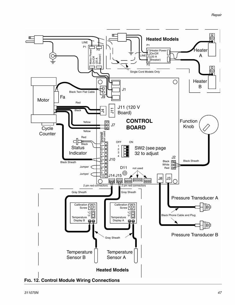
Table 6: Control Board Connectors (see FIG. 12)
Board Jack Pin Description
J1 n/a Main power from breakerJ2 n/a Function knobJ3 n/a Transducer AJ4 n/a Motor power (230 V units)J7 1, 2 Motor thermal overload signalJ8 n/a Transducer BJ9 n/a Fan
J10 1, 2 Status indicator3, 4 Not used5, 6 Cycle switch signal7-8 Jumpered
9-10 JumperedJ11 n/a Motor power (120 V)J14 n/a B temperature displayJ15 n/a A temperature display
Repair
311075N 47
FIG. 12. Control Module Wiring Connections
J1
J7
J10
Mot
or P
ower
O
n/O
ff (2
0 A
B
reak
er)
Heater Power On/Off (20 A Breaker)
Single Cord Models Only
J11 (120 V Board)J4 J1
1
J9
Heated Models
Heater A
Heater B
Function Knob
SW2 (see page 32 to adjust
Motor
Cycle Counter
Status Indicator
FaBlack Twin Flat Cable
Red
Black
Yellow
Yellow
Red
Black
Jumper
12345678
910 J15J14
J3J8
J2BlackWhite
Red
Pressure Transducer A
Pressure Transducer B
CONTROL BOARD
Black SheathBlack Sheath
Gray SheathGray Sheath
Gray Sheath
Black Phone Cable and Plug
Temperature Sensor B
Temperature Sensor A
Temperature Display B
Temperature Display A
2 pin red connectors2 pin red connectors
not used
not u
sed
Heated Models
Jumper
ONOFF
D11
LINE
LINE
P1P2
P2
P1
1234
°C°F
°C°F
CalibrationScrew
CalibrationScrew

Repair
48 311075N
Fluid Heaters (if supplied) Pressure Transducers
2. Remove access cover (39) at back of con-trol module to expose control board (406).
3. Disconnect transducer cables from J3 and J8 at board; see FIG. 12, page 47. Reverse A and B connections and check if status code follows the bad transducer, page 32.
4. Reconnect good transducer to proper con-nector. Disconnect failed transducer from board, and unscrew from base of fluid heater (heated units) or transducer mani-fold (nonheated units).
5. Install o-ring (60) on new transducer (58), FIG. 13.
6. Install transducer in heater or manifold. Mark board end of cable with tape (red=transducer A, blue=transducer B).
7. Route cable through channel to control module.
8. Connect transducer cable at board; see FIG. 12, page 47.
Fluid heater repair and parts information is included in manual 311210, which is supplied with heated units.
To replace a pressure transducer, see at right.
1. See Before Beginning Repair, page 39. Relieve pressure, page 27.
2. Control section of heater can be repaired in place. Remove heater to clean fluid section. See manual 311210 for heater repair and parts.
1. See Before Beginning Repair, page 39. Relieve pressure, page 27.
FIG. 13. Transducers
6058
Heated UnitsNonheated Units
6058
TI7026a
TI7027a

Repair
311075N 49
Drive Housing
Removal
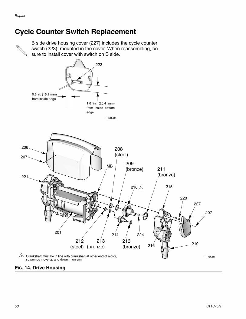
2. Remove screws (207) and end covers (221, 227), FIG. 14.
3. Disconnect pump inlet and outlet lines. Remove screws (220) and pull drive hous-ing (215) off motor (201) Connecting rod (216) will disengage from crankshaft (210).
4. Examine crankshaft (210), gear reducer (214), thrust washers (208, 212), and bear-ings (209, 211, 213).
Installation
1. Apply grease liberally to washers (208, 212), bearings (209, 211, 213), gear reducer (214), crankshaft (210), and inside drive housing (215). Grease is supplied with replacement parts kits.
2. Install bronze bearings (211, 213) in drive housing (215), as shown.
3. Install bronze bearings (209, 211) and steel washer (208) on crankshaft (210). Install bronze bearing (213) and steel washer (212) on gear reducer (214).
4. Install gear reducer (214) and crankshaft (210) into motor end bell (MB).
5. Push drive housing (215) onto motor (201). Install screws (220).
6. Install drive housing covers (221 on A side, 227 on B side) and screws (207). Pumps must be in phase (both at same position in stroke).
1. See Before Beginning Repair, page 39. Relieve pressure, page 27.
Examine connecting rod (216). If rod needs replacing, first remove the pump (219), page 41.
NOTICEDo not drop gear reducer (214) and crank-shaft (210) when removing drive housing (215). These parts may stay engaged in motor end bell (MB) or may pull away with drive housing.
B side crankshaft (210) includes the cycle counter magnet (224). When reassembling, be sure to install crank-shaft with magnet on B side.
If replacing crankshaft, remove magnet (224). Reinstall magnet in center of off-set shaft on new crankshaft. Position shaft in Park position.
Crankshaft (210) must be in line with crankshaft at other end of motor. Pumps will move up and down together.
If connecting rod (216) or pump (219) were removed, reassemble rod in hous-ing and install pump, page 41.
Repair
50 311075N
Cycle Counter Switch ReplacementB side drive housing cover (227) includes the cycle counter switch (223), mounted in the cover. When reassembling, be sure to install cover with switch on B side.
TI7028a
223
0.6 in. (15.2 mm)from inside edge
1.0 in. (25.4 mm)from inside bottomedge
FIG. 14. Drive Housing
Crankshaft must be in line with crankshaft at other end of motor, so pumps move up and down in unison.
1
227220
215
224
210
206
207
201
221
214
207
TI7029a
1
MB
216212
(steel)213(bronze)
208(steel)
211(bronze)
209(bronze)
219213
(bronze)
Repair
311075N 51
Electric Motor
Test Motor
If motor is not locked up by pumps, it can be tested using a 9 V battery. Open recirculating valves, disconnect J4 or J11 from control board, see FIG. 12, page 47. Touch jumpers from battery to motor connections. Motor should turn slowly and smoothly.
Removal
2. Remove four screws (207) and shroud (206). See FIG. 14.
3. Remove drive housing/pump assemblies, page 49.
4. Disconnect motor cables as follows:
a. Find control board at back of control module, see FIG. 12, page 47.
b. Unplug motor power connector from J4 (240 V units) or J11 (120 V units).
c. Unplug motor temp switch harness from connector J7.
d. Unplug cable (37) from fan (202). See FIG. 15.
e. Thread motor power switch harness out bottom of control module and cable channel, to free motor.
5. Remove screws holding motor to bracket. Lift motor off unit.
Installation
1. If replacing motor, install fan assembly and fan mount threaded bushing on new motor.
2. Place motor and fan on unit. Thread motor switch harness into control module.
3. Fasten motor with screws underneath. Do not tighten yet.
4. Plug 3-pin connector J7 to board.
5. Plug Motor Power switch harness to con-nector J4 (240 V units) or J11 (120 V units).
6. Install drive housing/pump assemblies, page 49. Reconnect inlet assemblies to pumps.
7. Tighten motor mounting screws.
8. Return to service.
If replacing a component with electrical cabling, remove one supply tank, page 39.
1. See Before Beginning Repair, page 39. Relieve pressure, page 27.
NOTICEMotor is heavy. Two people may be required to lift.

Repair
52 311075N
Motor Brushes
2. See instruction sheet 406582, included with Brush Repair Kit 287735. Remove old brushes and install new ones supplied in kit.
Fan1. Disconnect fan cable (37) from fan (202).
With Motor Power on, test cable connector for line voltage (120 V or 240 V).
2. If voltage is correct, fan is defective. Remove screws holding fan to shield (206). Install new fan in reverse order.
3. If voltage is not correct, check fan cable connection at J9 on control board; see FIG. 12, page 47.
Replace brushes worn to less than 1/2 in. (13 mm). Brushes wear differently on each side of motor; check both sides. Brush Repair Kit 287735 is available; kit includes instruction sheet 406582.
Motor commutator should be smooth. If not, resurface commutator or replace motor.
1. See Before Beginning Repair, page 39. Relieve pressure, page 27.
FIG. 15. Fan
202
TI7030a
37

Repair
311075N 53

Parts
54 311075N
PartsPart No. AP9570 or CS9570, 120 V, 15 A, Heated PackagePart No. AP9571 or CS9571, 240 V, 10 A, Heated PackagePart No. AP9572 or CS9572, 240 V, 20 A, Heated Package
TI6988b
101
103
102
61
61
Proportioner Description 101 102 103
AP9570 120 V, 15 A, Heated Package
249570see page 56
249499see page 63
249810see 309550
CS9570 CS22WDsee 312666
AP9571 240 V, 10 A, Heated Package
249571see page 56
249499see page 63
249810see 309550
CS9571 CS22WDsee 312666
AP9572 240 V, 20 A, Heated Package
249572see page 56
249499see page 63
249810see 309550
CS9572 CS22WDsee 312666

Parts
311075N 55
Part No. 249806, 120 V, 15 A, Nonheated PackagePart No. 249808, 240 V, 10 A, Nonheated Package
TI6990b
101
103
102
61
61
Ref. Part Description Qty101 249576 PROPORTIONER, nonheated,
120 V, 15 A; see page 60; 249806 only
1
249577 PROPORTIONER, heated, 240 V, 10 A; see page 60; 249808 only
1
102 249633 HOSE BUNDLE, non-insulated; see page 63
1
103 249834 GUN, 2K Ultra-Lite; see 309000 and 311230
1
Ref. Part Description Qty
Parts
56 311075N
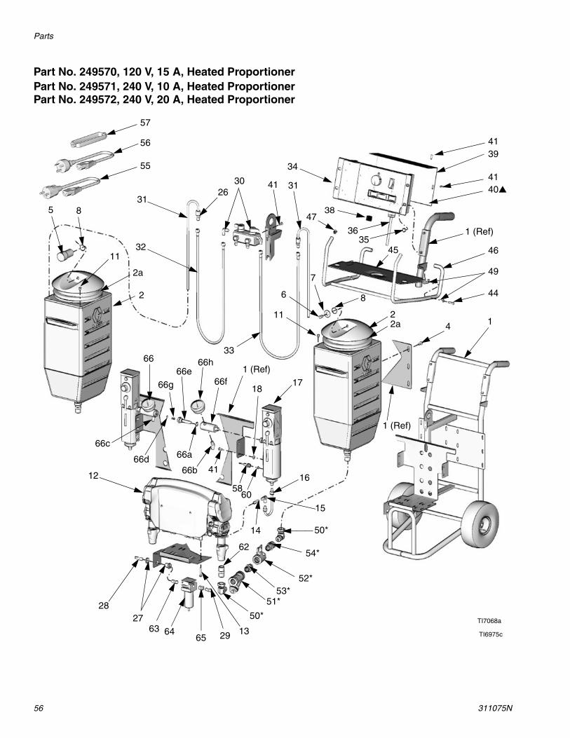
Part No. 249570, 120 V, 15 A, Heated ProportionerPart No. 249571, 240 V, 10 A, Heated ProportionerPart No. 249572, 240 V, 20 A, Heated Proportioner
39
41
1 (Ref)
41
49
44
14
1 (Ref)
2
8
7
6
11
3366h
66f1 (Ref)
17
4738
34
314130
31
32
85
11
2
66e
66a
41
18
16
50*14
15
54*
52*53*
51*
50*
1329
2728
12
62
40
2a
4535
2a
66g
46
TI6975c
6058
36
TI7068a
57
55
56
63 6465
26
66b66d
66c
66
Parts
311075N 57
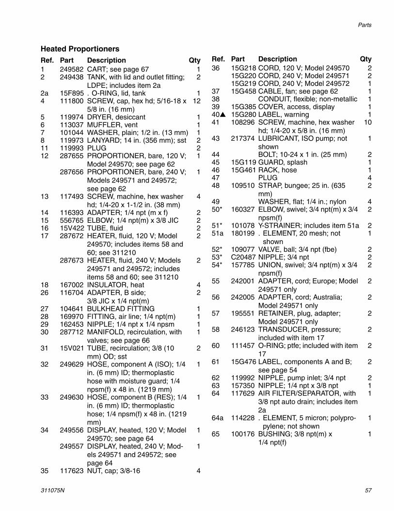
Heated ProportionersRef. Part Description Qty1 249582 CART; see page 67 12 249438 TANK, with lid and outlet fitting;
LDPE; includes item 2a2
2a 15F895 . O-RING, lid, tank 14 111800 SCREW, cap, hex hd; 5/16-18 x
5/8 in. (16 mm)12
5 119974 DRYER, desiccant 16 113037 MUFFLER, vent 17 101044 WASHER, plain; 1/2 in. (13 mm) 18 119973 LANYARD; 14 in. (356 mm); sst 211 119993 PLUG 212 287655 PROPORTIONER, bare, 120 V;
Model 249570; see page 621
287656 PROPORTIONER, bare, 240 V; Models 249571 and 249572; see page 62
1
13 117493 SCREW, machine, hex washer hd; 1/4-20 x 1-1/2 in. (38 mm)
4
14 116393 ADAPTER; 1/4 npt (m x f) 215 556765 ELBOW; 1/4 npt(m) x 3/8 JIC 216 15V422 TUBE, fluid 217 287672 HEATER, fluid, 120 V; Model
249570; includes items 58 and 60; see 311210
2
287673 HEATER, fluid, 240 V; Models 249571 and 249572; includes items 58 and 60; see 311210
2
18 167002 INSULATOR, heat 426 116704 ADAPTER, B side;
3/8 JIC x 1/4 npt(m)2
27 104641 BULKHEAD FITTING 128 169970 FITTING, air line; 1/4 npt(m) 129 162453 NIPPLE; 1/4 npt x 1/4 npsm 130 287712 MANIFOLD, recirculation, with
valves; see page 661
31 15V021 TUBE, recirculation; 3/8 (10 mm) OD; sst
2
32 249629 HOSE, component A (ISO); 1/4 in. (6 mm) ID; thermoplastic hose with moisture guard; 1/4 npsm(f) x 48 in. (1219 mm)
1
33 249630 HOSE, component B (RES); 1/4 in. (6 mm) ID; thermoplastic hose; 1/4 npsm(f) x 48 in. (1219 mm)
1
34 249556 DISPLAY, heated, 120 V; Model 249570; see page 64
1
249557 DISPLAY, heated, 240 V; Mod-els 249571 and 249572; see page 64
1
35 117623 NUT, cap; 3/8-16 4
36 15G218 CORD, 120 V; Model 249570 215G220 CORD, 240 V; Model 249571 215G219 CORD, 240 V; Model 249572 1
37 15G458 CABLE, fan; see page 62 138 CONDUIT, flexible; non-metallic 139 15G385 COVER, access, display 140 15G280 LABEL, warning 141 108296 SCREW, machine, hex washer
hd; 1/4-20 x 5/8 in. (16 mm)10
43 217374 LUBRICANT, ISO pump; not shown
1
44 BOLT; 10-24 x 1 in. (25 mm) 245 15G119 GUARD, splash 146 15G461 RACK, hose 147 PLUG 448 109510 STRAP, bungee; 25 in. (635
mm)2
49 WASHER, flat; 1/4 in.; nylon 450* 160327 ELBOW, swivel; 3/4 npt(m) x 3/4
npsm(f)2
51* 101078 Y-STRAINER; includes item 51a 251a 180199 . ELEMENT, 20 mesh; not
shown1
52* 109077 VALVE, ball; 3/4 npt (fbe) 253* C20487 NIPPLE; 3/4 npt 254* 157785 UNION, swivel; 3/4 npt(m) x 3/4
npsm(f)2
55 242001 ADAPTER, cord; Europe; Model 249571 only
2
56 242005 ADAPTER, cord; Australia; Model 249571 only
2
57 195551 RETAINER, plug, adapter; Model 249571 only
2
58 246123 TRANSDUCER, pressure; included with item 17
2
60 111457 O-RING; ptfe; included with item 17
2
61 15G476 LABEL, components A and B; see page 54
2
62 119992 NIPPLE, pump inlet; 3/4 npt 263 157350 NIPPLE; 1/4 npt x 3/8 npt 164 117629 AIR FILTER/SEPARATOR, with
3/8 npt auto drain; includes item 2a
1
64a 114228 . ELEMENT, 5 micron; polypro-pylene; not shown
1
65 100176 BUSHING; 3/8 npt(m) x 1/4 npt(f)
1
Ref. Part Description Qty
Parts
58 311075N
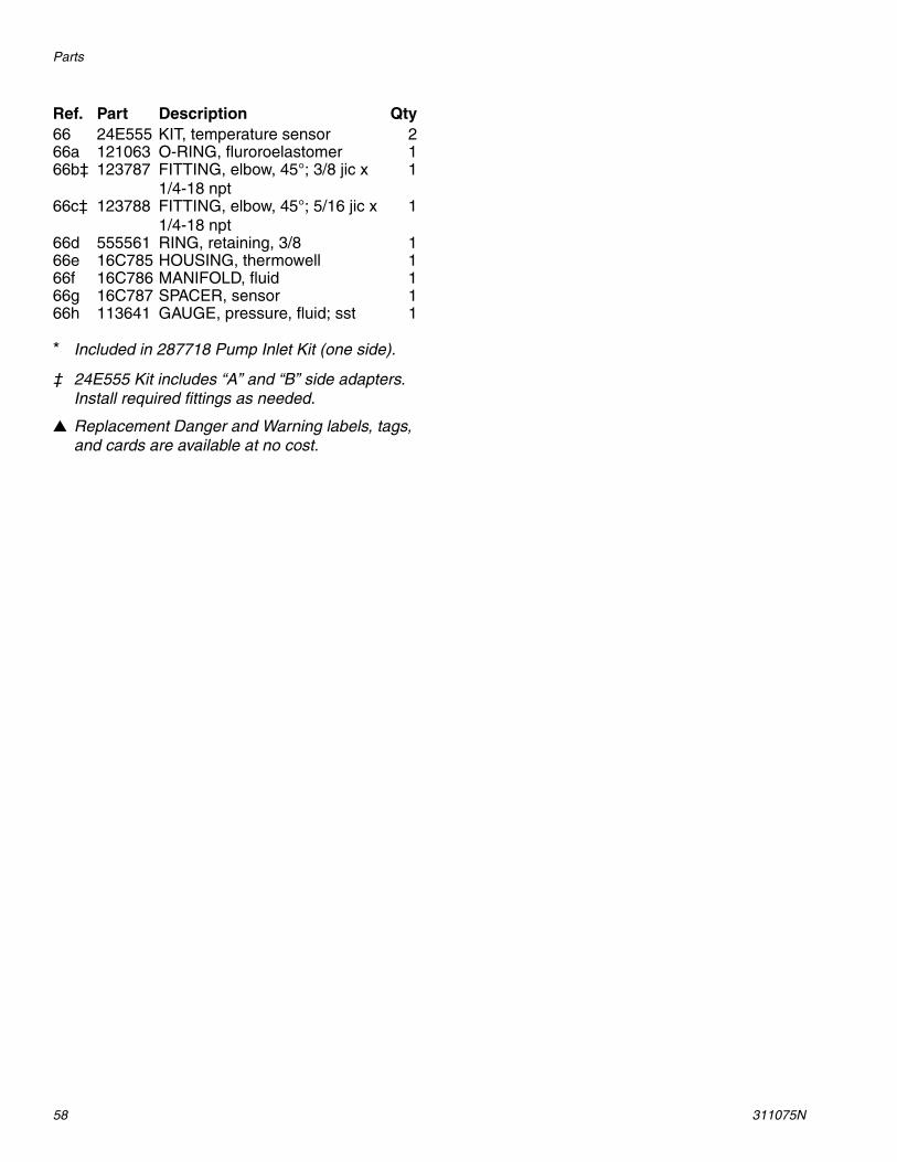
* Included in 287718 Pump Inlet Kit (one side).
‡ 24E555 Kit includes “A” and “B” side adapters. Install required fittings as needed.
Replacement Danger and Warning labels, tags, and cards are available at no cost.
66 24E555 KIT, temperature sensor 266a 121063 O-RING, fluroroelastomer 166b‡ 123787 FITTING, elbow, 45°; 3/8 jic x
1/4-18 npt1
66c‡ 123788 FITTING, elbow, 45°; 5/16 jic x 1/4-18 npt
1
66d 555561 RING, retaining, 3/8 166e 16C785 HOUSING, thermowell 166f 16C786 MANIFOLD, fluid 166g 16C787 SPACER, sensor 166h 113641 GAUGE, pressure, fluid; sst 1
Ref. Part Description Qty

Parts
311075N 59
Parts
60 311075N
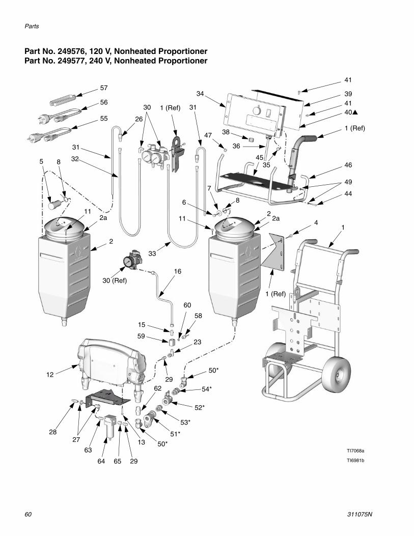
Part No. 249576, 120 V, Nonheated ProportionerPart No. 249577, 240 V, Nonheated Proportioner
3941
1 (Ref)
41
49
44
40
14
1 (Ref)
2
8
7
6
11
33
47 38
34
311 (Ref)30
31
3285
11
2
59
16
50*
15
54*
52*
53*
51*
50*13
29
2728
12
62
2a
4535
2a
30 (Ref)
23
46
60
58
29
TI6981b
36
TI7068a
57
55
56
63
64 65
26
Parts
311075N 61
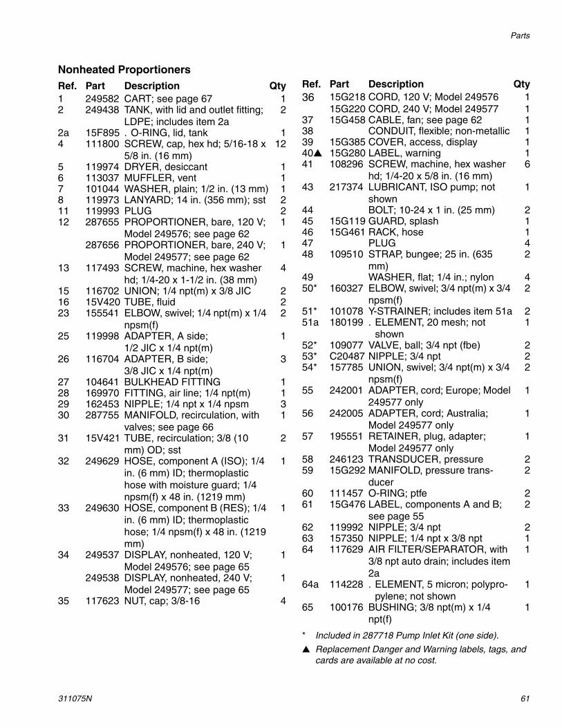
Nonheated Proportioners
* Included in 287718 Pump Inlet Kit (one side).
Replacement Danger and Warning labels, tags, and cards are available at no cost.
Ref. Part Description Qty1 249582 CART; see page 67 12 249438 TANK, with lid and outlet fitting;
LDPE; includes item 2a2
2a 15F895 . O-RING, lid, tank 14 111800 SCREW, cap, hex hd; 5/16-18 x
5/8 in. (16 mm)12
5 119974 DRYER, desiccant 16 113037 MUFFLER, vent 17 101044 WASHER, plain; 1/2 in. (13 mm) 18 119973 LANYARD; 14 in. (356 mm); sst 211 119993 PLUG 212 287655 PROPORTIONER, bare, 120 V;
Model 249576; see page 621
287656 PROPORTIONER, bare, 240 V; Model 249577; see page 62
1
13 117493 SCREW, machine, hex washer hd; 1/4-20 x 1-1/2 in. (38 mm)
4
15 116702 UNION; 1/4 npt(m) x 3/8 JIC 216 15V420 TUBE, fluid 223 155541 ELBOW, swivel; 1/4 npt(m) x 1/4
npsm(f)2
25 119998 ADAPTER, A side; 1/2 JIC x 1/4 npt(m)
1
26 116704 ADAPTER, B side; 3/8 JIC x 1/4 npt(m)
3
27 104641 BULKHEAD FITTING 128 169970 FITTING, air line; 1/4 npt(m) 129 162453 NIPPLE; 1/4 npt x 1/4 npsm 330 287755 MANIFOLD, recirculation, with
valves; see page 661
31 15V421 TUBE, recirculation; 3/8 (10 mm) OD; sst
2
32 249629 HOSE, component A (ISO); 1/4 in. (6 mm) ID; thermoplastic hose with moisture guard; 1/4 npsm(f) x 48 in. (1219 mm)
1
33 249630 HOSE, component B (RES); 1/4 in. (6 mm) ID; thermoplastic hose; 1/4 npsm(f) x 48 in. (1219 mm)
1
34 249537 DISPLAY, nonheated, 120 V; Model 249576; see page 65
1
249538 DISPLAY, nonheated, 240 V; Model 249577; see page 65
1
35 117623 NUT, cap; 3/8-16 4
36 15G218 CORD, 120 V; Model 249576 115G220 CORD, 240 V; Model 249577 1
37 15G458 CABLE, fan; see page 62 138 CONDUIT, flexible; non-metallic 139 15G385 COVER, access, display 140 15G280 LABEL, warning 141 108296 SCREW, machine, hex washer
hd; 1/4-20 x 5/8 in. (16 mm)6
43 217374 LUBRICANT, ISO pump; not shown
1
44 BOLT; 10-24 x 1 in. (25 mm) 245 15G119 GUARD, splash 146 15G461 RACK, hose 147 PLUG 448 109510 STRAP, bungee; 25 in. (635
mm)2
49 WASHER, flat; 1/4 in.; nylon 450* 160327 ELBOW, swivel; 3/4 npt(m) x 3/4
npsm(f)2
51* 101078 Y-STRAINER; includes item 51a 251a 180199 . ELEMENT, 20 mesh; not
shown1
52* 109077 VALVE, ball; 3/4 npt (fbe) 253* C20487 NIPPLE; 3/4 npt 254* 157785 UNION, swivel; 3/4 npt(m) x 3/4
npsm(f)2
55 242001 ADAPTER, cord; Europe; Model 249577 only
1
56 242005 ADAPTER, cord; Australia; Model 249577 only
1
57 195551 RETAINER, plug, adapter; Model 249577 only
1
58 246123 TRANSDUCER, pressure 259 15G292 MANIFOLD, pressure trans-
ducer2
60 111457 O-RING; ptfe 261 15G476 LABEL, components A and B;
see page 552
62 119992 NIPPLE; 3/4 npt 263 157350 NIPPLE; 1/4 npt x 3/8 npt 164 117629 AIR FILTER/SEPARATOR, with
3/8 npt auto drain; includes item 2a
1
64a 114228 . ELEMENT, 5 micron; polypro-pylene; not shown
1
65 100176 BUSHING; 3/8 npt(m) x 1/4 npt(f)
1
Ref. Part Description Qty
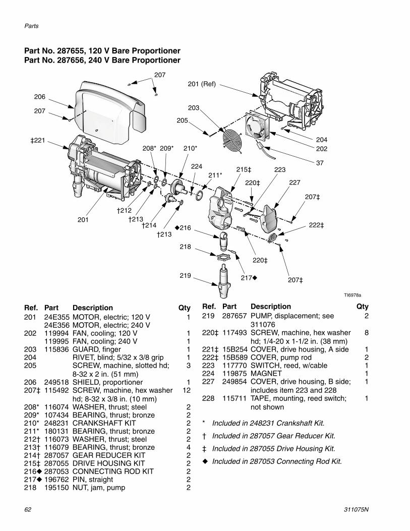
Parts
62 311075N
Part No. 287655, 120 V Bare ProportionerPart No. 287656, 240 V Bare Proportioner
* Included in 248231 Crankshaft Kit.
† Included in 287057 Gear Reducer Kit.
‡ Included in 287055 Drive Housing Kit.
Included in 287053 Connecting Rod Kit.
207201 (Ref)
202204
203
207‡
227
223
220‡
215‡211*
224
210*209*208*
205
206
207
201
‡221
†212†213
†214†213
216
218
219 217
220‡
222‡
TI6978a
37
207‡
Ref. Part Description Qty201 24E355 MOTOR, electric; 120 V 1
24E356 MOTOR, electric; 240 V202 119994 FAN, cooling; 120 V 1
119995 FAN, cooling; 240 V 1203 115836 GUARD, finger 1204 RIVET, blind; 5/32 x 3/8 grip 1205 SCREW, machine, slotted hd;
8-32 x 2 in. (51 mm)3
206 249518 SHIELD, proportioner 1207‡ 115492 SCREW, machine, hex washer
hd; 8-32 x 3/8 in. (10 mm)12
208* 116074 WASHER, thrust; steel 2209* 107434 BEARING, thrust; bronze 2210* 248231 CRANKSHAFT KIT 2211* 180131 BEARING, thrust; bronze 2212† 116073 WASHER, thrust; steel 2213† 116079 BEARING, thrust; bronze 4214† 287057 GEAR REDUCER KIT 2215‡ 287055 DRIVE HOUSING KIT 2216 287053 CONNECTING ROD KIT 2217 196762 PIN, straight 2218 195150 NUT, jam, pump 2
219 287657 PUMP, displacement; see 311076
2
220‡ 117493 SCREW, machine, hex washer hd; 1/4-20 x 1-1/2 in. (38 mm)
8
221‡ 15B254 COVER, drive housing, A side 1222‡ 15B589 COVER, pump rod 2223 117770 SWITCH, reed, w/cable 1224 119875 MAGNET 1227 249854 COVER, drive housing, B side;
includes item 223 and 2281
228 115711 TAPE, mounting, reed switch; not shown
1
Ref. Part Description Qty

Parts
311075N 63
Part No. 249499, Insulated Hose Bundle with recirculation lines
Part No. 249633, Non-insulated Hose Bundle without recirculation lines
TI6991a
302 (Ref)302
303 (Ref)
305 303
304
301
Ref. Part Description Qty301 249508 HOSE, fluid (component A),
moisture guard; 1/4 in. (6 mm) ID; no. 5 JIC fittings (mxf); 35 ft (10.7 m)
2
302 249509 HOSE, fluid (component B); 1/4 in. (6 mm) ID; no. 6 JIC fittings (mxf); 35 ft (10.7 m)
2
303 15G342 HOSE, air; 1/4 in. (6 mm) ID; 1/4 npsm (fbe); 35 ft (10.7 m)
1
304 buy locally
TUBE, foam, insulated; 1-3/8 in. (35 mm) ID; 31 ft (9.5 m)
1
305 156971 NIPPLE; 1/4 npt; for joining air line to another hose bundle
1
Ref. Part Description Qty
302 (Ref)
302
303
301
TI6992a
305
Ref. Part Description Qty301 249508 HOSE, fluid (component A),
moisture guard; 1/4 in. (6 mm) ID; no. 5 JIC fittings (mxf); 35 ft (10.7 m)
1
302 249509 HOSE, fluid (component B); 1/4 in. (6 mm) ID; no. 6 JIC fittings (mxf); 35 ft (10.7 m)
1
303 15G342 HOSE, air; 1/4 in. (6 mm) ID; 1/4 npsm (fbe); 35 ft (10.7 m)
1
305 156971 NIPPLE; 1/4 npt; for joining air line to another hose bundle
1
Ref. Part Description Qty

Parts
64 311075N
Part No. 249556, 120 V Heated DisplayPart No. 249557, 240 V Heated Display
405 416a
416
416a
415
417
406407
408
412411
410
409
403
421
401
404 402
410
TI6979a
424
402
413
414
404 (Ref)
Ref. Part Description Qty401 15F984 PLATE 1402 119927 SWITCH, motor or heater
power, with circuit breaker2
403 15G386 MODULE, display, temperature; includes (1) item 402 and (2) item 424
1
404 249494 POTENTIOMETER 1405 119930 INDICATOR, status, LED 1406 24G886 BOARD, control; 120 V units
only1
24G887 BOARD, control; 240 V units only
1
407 15G230 CABLE, harness 1408 107156 SCREW, machine, pan hd 7409 113505 NUT, keps, hex hd 10410 119898 BULKHEAD FITTING, cable 2
411 101765 GROMMET 1412 116773 CONNECTOR, plug 1413 15C866 WIRE, jumper 2414 15G279 LABEL, display 1415 15G053 PLATE, detent 1416 249453 KNOB, function; includes item
416a1
416a 101118 . SCREW, set; no. 10 x 1/4 in. (6 mm)
2
417 15G454 LABEL, startup, heated 1421 15G384 ENCLOSURE 1424 119869 DISPLAY, temperature, with
sensor2
425 DUAL TERMINAL; not shown 2
Ref. Part Description Qty

Parts
311075N 65
Part No. 249537, 120 V Nonheated DisplayPart No. 249538, 240 V Nonheated Display
403 405
416a
416
416a
415
417
406
412
407
408
411423
410
409
421
401
404402
TI6983a413
414
404 (Ref)
Ref. Part Description Qty401 15F984 PLATE 1402 119927 SWITCH, motor power, with cir-
cuit breaker1
403 15G408 COVER, display 1404 249494 POTENTIOMETER 1405 119930 INDICATOR, status, LED 1406 24G886 BOARD, control; 120 V units
only1
24G887 BOARD, control; 240 V units only
1
407 15G230 CABLE, harness 1408 107156 SCREW, machine, pan hd 7409 113505 NUT, keps, hex hd 10410 119897 BULKHEAD FITTING, cable 1411 101765 GROMMET 1412 116773 CONNECTOR, plug 1413 WIRE, jumper 2
414 15G279 LABEL, display 1415 15G053 PLATE, detent 1416 249453 KNOB, function; includes item
416a1
416a 101118 . SCREW, set; no. 10 x 1/4 in. (6 mm)
2
417 15G281 LABEL, startup, unheated 1421 15G384 ENCLOSURE 1423 PLUG 1
Ref. Part Description Qty

Parts
66 311075N
Part No. 287712 Recirculation Manifold, Heated Models
Replacement Danger and Warning labels, tags, and cards are available at no cost.
Part No. 287755 Recirculation Manifold, Nonheated Models
505
504
503
501
502
507
509510
508
506
TI6977a
503a503b512
Ref. Part Description Qty501 15F870 MANIFOLD, recirculation 1502 111763 ELBOW; 1/4 npt (mbe) 2503 239914 VALVE, recirc/spray; includes
items 503a, 503b2
503a 15E022 . SEAT 1503b 111699 . GASKET 1504 224807 BASE, valve 2505 187625 HANDLE, valve, drain 2506 111600 PIN, grooved 2507 100721 PLUG, pipe; 1/4 npt(m) 2508 100840 ELBOW, street; 1/4 npt(m) x 1/4
npsm(f)2
509 116704 ADAPTER; 3/8 JIC x 1/4 npt(m) 1510 119998 ADAPTER; 5/16 JIC x 1/4
npt(m)1
512 189285 LABEL, warning 1
505
504
503
501
502
509
510
507
506
511
508
TI6982a
503a503b
Ref. Part Description Qty501 15F870 MANIFOLD, recirculation 1502 111763 ELBOW; 1/4 npt (mbe) 4503 239914 VALVE, recirc/spray; includes
items 503a, 503b2
503a 15E022 . SEAT 1503b 111699 . GASKET 1504 224807 BASE, valve 2505 187625 HANDLE, valve, drain 2506 111600 PIN, grooved 2507 113641 GAUGE, pressure, fluid 2508 116504 TEE; 1/4 npt(m) x 1/4 npt(f) run;
1/4 npt(f) branch2
509 116704 ADAPTER; 3/8 JIC x 1/4 npt(m) 1510 119998 ADAPTER; 5/16 JIC x 1/4
npt(m)1
511 556765 ELBOW, tube; 1/4 npt(m) x 3/8 in. (10 mm) OD tube
2

Parts
311075N 67
Part No. 249582, Cart
Ref. Part Description Qty602 154636 WASHER, flat 4603 116411 SPRING 2604 116477 WASHER, flat; nylon 4605 116478 WHEEL, pneumatic 2606 101242 RING, retaining 2607 GRIP, handle 2
607
602
603
602
604 605
604
606
TI6976a
Suggested Spare Replacement Parts
68 311075N
Suggested Spare Replacement Parts
Keep the following spare parts on hand to reduce downtime.
All Units Heated Units Only
Accessories
Part Description119974 DRYER, desiccant15F895 O-RING, lid, tank119927 SWITCH, motor or heater power, with cir-
cuit breaker113641 GAUGE, pressure, fluid; sst101078 Y-STRAINER; includes 180199 element180199 ELEMENT, Y-strainer, 20 mesh114228 ELEMENT, air filter, 5 micron; polypropyl-
ene239914 VALVE, recirc/spray; includes seat and
gasket249494 POTENTIOMETER, control knob24G886 BOARD, control; 120 V units only24G887 BOARD, control; 240 V units only246123 TRANSDUCER, pressure287657 PUMP, displacement; fits either side287718 INLET KIT, tank to pump249855 REPAIR KIT, displacement pump;
includes seals, balls, bearings, intake valve seat)
Part Description119869 DISPLAY, temperature, with sensor119857 FUSE, heater over-temperature119797 THERMOSTAT, heater15F770 HEATER ELEMENT; 120 V units only15F771 HEATER ELEMENT; 240 V units only
Part Description249815 GUN, Fusion MP with 4-hose manifold249634 KIT, 2k Ultra-Lite, restrictor valve, cold
spray249635 KIT, 2k Ultra-Lite, extension, joint fill
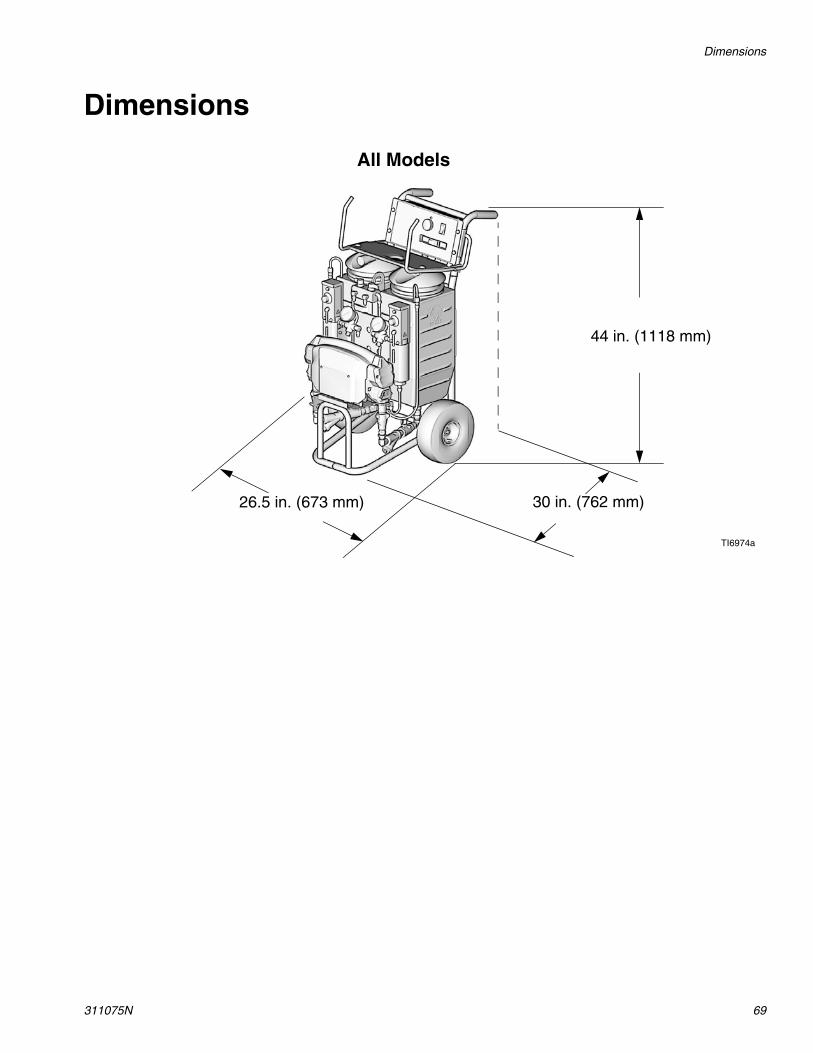
Dimensions
311075N 69
Dimensions
TI6974a
26.5 in. (673 mm)
44 in. (1118 mm)
30 in. (762 mm)
All Models
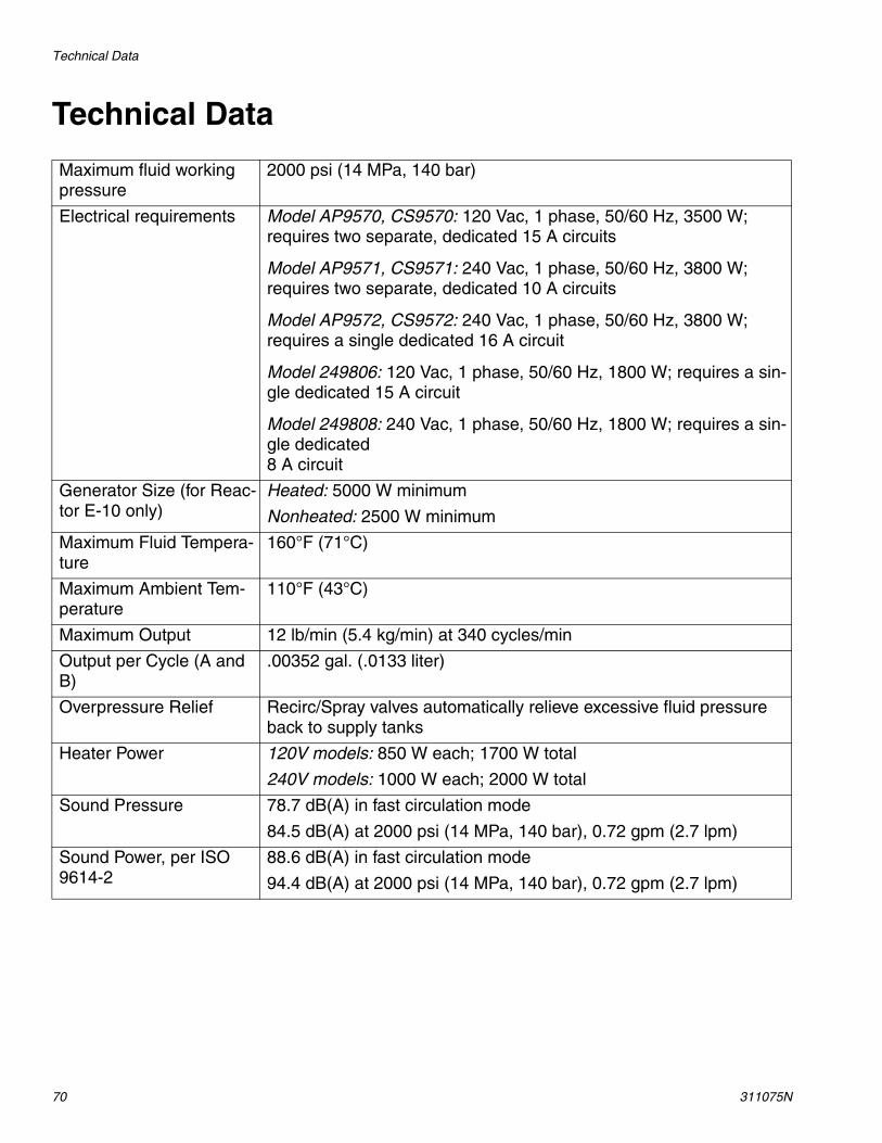
Technical Data
70 311075N
Technical Data
Maximum fluid working pressure
2000 psi (14 MPa, 140 bar)
Electrical requirements Model AP9570, CS9570: 120 Vac, 1 phase, 50/60 Hz, 3500 W; requires two separate, dedicated 15 A circuits
Model AP9571, CS9571: 240 Vac, 1 phase, 50/60 Hz, 3800 W; requires two separate, dedicated 10 A circuits
Model AP9572, CS9572: 240 Vac, 1 phase, 50/60 Hz, 3800 W; requires a single dedicated 16 A circuit
Model 249806: 120 Vac, 1 phase, 50/60 Hz, 1800 W; requires a sin-gle dedicated 15 A circuit
Model 249808: 240 Vac, 1 phase, 50/60 Hz, 1800 W; requires a sin-gle dedicated 8 A circuit
Generator Size (for Reac-tor E-10 only)
Heated: 5000 W minimum
Nonheated: 2500 W minimum
Maximum Fluid Tempera-ture
160°F (71°C)
Maximum Ambient Tem-perature
110°F (43°C)
Maximum Output 12 lb/min (5.4 kg/min) at 340 cycles/min
Output per Cycle (A and B)
.00352 gal. (.0133 liter)
Overpressure Relief Recirc/Spray valves automatically relieve excessive fluid pressure back to supply tanks
Heater Power 120V models: 850 W each; 1700 W total
240V models: 1000 W each; 2000 W total
Sound Pressure 78.7 dB(A) in fast circulation mode
84.5 dB(A) at 2000 psi (14 MPa, 140 bar), 0.72 gpm (2.7 lpm)
Sound Power, per ISO 9614-2
88.6 dB(A) in fast circulation mode
94.4 dB(A) at 2000 psi (14 MPa, 140 bar), 0.72 gpm (2.7 lpm)
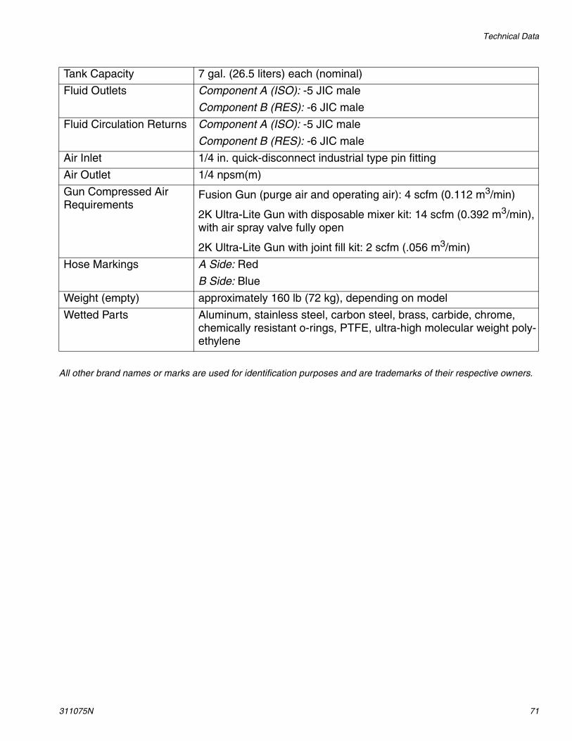
Technical Data
311075N 71
All other brand names or marks are used for identification purposes and are trademarks of their respective owners.
Tank Capacity 7 gal. (26.5 liters) each (nominal)
Fluid Outlets Component A (ISO): -5 JIC male
Component B (RES): -6 JIC male
Fluid Circulation Returns Component A (ISO): -5 JIC male
Component B (RES): -6 JIC male
Air Inlet 1/4 in. quick-disconnect industrial type pin fitting
Air Outlet 1/4 npsm(m)
Gun Compressed Air Requirements
Fusion Gun (purge air and operating air): 4 scfm (0.112 m3/min)
2K Ultra-Lite Gun with disposable mixer kit: 14 scfm (0.392 m3/min), with air spray valve fully open
2K Ultra-Lite Gun with joint fill kit: 2 scfm (.056 m3/min)
Hose Markings A Side: Red
B Side: Blue
Weight (empty) approximately 160 lb (72 kg), depending on model
Wetted Parts Aluminum, stainless steel, carbon steel, brass, carbide, chrome, chemically resistant o-rings, PTFE, ultra-high molecular weight poly-ethylene
All written and visual data contained in this document reflects the latest product information available at the time of publication. Graco reserves the right to make changes at any time without notice.
Original instructions. This manual contains English. MM 311075
Graco Headquarters: MinneapolisInternational Offices: Belgium, China, Japan, Korea
GRACO INC. P.O. BOX 1441 MINNEAPOLIS, MN 55440-1441Copyright 2005, Graco Inc. is registered to ISO 9001
www.graco.comRevised 05/2011
Graco Standard WarrantyGraco warrants all equipment referenced in this document which is manufactured by Graco and bearing its name to be free from defects in material and workmanship on the date of sale to the original purchaser for use. With the exception of any special, extended, or limited warranty published by Graco, Graco will, for a period of twelve months from the date of sale, repair or replace any part of the equipment determined by Graco to be defective. This warranty applies only when the equipment is installed, operated and maintained in accordance with Graco’s written recommendations.
This warranty does not cover, and Graco shall not be liable for general wear and tear, or any malfunction, damage or wear caused by faulty installation, misapplication, abrasion, corrosion, inadequate or improper maintenance, negligence, accident, tampering, or substitution of non-Graco component parts. Nor shall Graco be liable for malfunction, damage or wear caused by the incompatibility of Graco equipment with structures, accessories, equipment or materials not supplied by Graco, or the improper design, manufacture, installation, operation or maintenance of structures, accessories, equipment or materials not supplied by Graco.
This warranty is conditioned upon the prepaid return of the equipment claimed to be defective to an authorized Graco distributor for verification of the claimed defect. If the claimed defect is verified, Graco will repair or replace free of charge any defective parts. The equipment will be returned to the original purchaser transportation prepaid. If inspection of the equipment does not disclose any defect in material or workmanship, repairs will be made at a reasonable charge, which charges may include the costs of parts, labor, and transportation.
THIS WARRANTY IS EXCLUSIVE, AND IS IN LIEU OF ANY OTHER WARRANTIES, EXPRESS OR IMPLIED, INCLUDING BUT NOT LIMITED TO WARRANTY OF MERCHANTABILITY OR WARRANTY OF FITNESS FOR A PARTICULAR PURPOSE.
Graco’s sole obligation and buyer’s sole remedy for any breach of warranty shall be as set forth above. The buyer agrees that no other remedy (including, but not limited to, incidental or consequential damages for lost profits, lost sales, injury to person or property, or any other incidental or consequential loss) shall be available. Any action for breach of warranty must be brought within two (2) years of the date of sale.
GRACO MAKES NO WARRANTY, AND DISCLAIMS ALL IMPLIED WARRANTIES OF MERCHANTABILITY AND FITNESS FOR A PARTICULAR PURPOSE, IN CONNECTION WITH ACCESSORIES, EQUIPMENT, MATERIALS OR COMPONENTS SOLD BUT NOT MANUFACTURED BY GRACO. These items sold, but not manufactured by Graco (such as electric motors, switches, hose, etc.), are subject to the warranty, if any, of their manufacturer. Graco will provide purchaser with reasonable assistance in making any claim for breach of these warranties.
In no event will Graco be liable for indirect, incidental, special or consequential damages resulting from Graco supplying equipment hereunder, or the furnishing, performance, or use of any products or other goods sold hereto, whether due to a breach of contract, breach of warranty, the negligence of Graco, or otherwise.
FOR GRACO CANADA CUSTOMERSThe Parties acknowledge that they have required that the present document, as well as all documents, notices and legal proceedings entered into, given or instituted pursuant hereto or relating directly or indirectly hereto, be drawn up in English. Les parties reconnaissent avoir convenu que la rédaction du présente document sera en Anglais, ainsi que tous documents, avis et procédures judiciaires exécutés, donnés ou intentés, à la suite de ou en rapport, directement ou indirectement, avec les procédures concernées.
Graco Information For the latest information about Graco products, visit www.graco.com.
TO PLACE AN ORDER, contact your Graco distributor or call to identify the nearest distributor.Phone: 612-623-6921 or Toll Free: 1-800-328-0211 Fax: 612-378-3505