Embed Size (px)
Citation preview

MONITORING PLAN
FOR THE
PURECELL 400
AT
THE OCTAGON IN NEW YORK, NY
August 30, 2011
Submitted to:
United Technologies Power
195 Governor's Hwy
South Windsor, CT 06074
NYSERDA
17 Columbia Circle
Albany, NY 12203
Submitted by:
CDH Energy Corp.
PO Box 641
132 Albany Street
Cazenovia, NY 13035
(315) 655-1063


TABLE OF CONTENTS
Introduction ..................................................................................................................................... 1
System Description ......................................................................................................................... 1 Heat Recovery Monitoring System ................................................................................................. 2 Calculated Quantities ...................................................................................................................... 5 Project Web Site ............................................................................................................................. 7
Appendix A – Monitoring System Details

CDH Energy 1 August 2011
Introduction
This plan describes our approach to monitoring the performance of the fuel cell system installed
at The Octagon apartment complex on Roosevelt Island in New York, NY. The UTC Power
PureCell® Model 400 fuel cell provides clean and efficient electric power and thermal output to
the complex. This fuel cell is expected to supply some of the apartment’s electricity
requirements in addition to standby power in the event of a power grid failure. The complex will
also recover heat from the fuel cell to use for space and Domestic Hot Water (DHW) heating.
System Description The PureCell® Model 400 is installed in front of the apartment complex. The fuel cell (FC) has
separate electrical feeds for parallel operation with the utility or to provide backup power when
isolated from the grid. The fuel cell is able to provide 400 kW of electrical power and up to 1.7
million Btu/h of heat. If fully utilized, the fuel cell can obtain a thermal efficiency near 90%.
Power Output: 400 kW 480V, 3ph Heat Output: 1.71 MMBtu/h (low temp) 0.79 MMBtu/h (high temp)
Figure 1. PureCell 400 Unit
Most of the thermal output from the FC is used to provide space conditioning and water heating
for the building. The low temperature loop supplies 140ºF water to meet space heating and
DHW tank loads (see Figure 2 and Figure 3).

CDH Energy 2 August 2011
Figure 2. Fuel Cell and DHW Piping Schematic at The Octagon
Heat Recovery Monitoring System The heat recovery monitoring system (HRM) has been designed to capture the electrical and
thermal performance of the system. Table 1 summarizes the measurements that will be captured
at the site.
Figure 3 shows where the measurements will be made in the thermal loops. Figure 4 and Figure
5 show the locations for the temperature measurements and flow meters in thermal circuits.
Flow and temperature sensors are installed for two thermal loops: low temperature and coolant
water.
Data are extracted from the Power Plant Controller (PPC) via MODBUS TCP. The Obvius
AcquiSuite datalogger logs the required data.
Table 1. Summary of Measured and Collected Data at the Site
Channel /
Source Data Pt Description Instrument / Meter
Signal /
Register Eng Units Wire Notes
Main-1 TLS Low Temp Supply Temp (from FC) 10k Thermistor, Type 2 ohm °F 43
Main-2 TLR Low Temp Return Temp (to FC) 10k Thermistor, Type 2 ohm °F 42
Main-3 TCWS Cooling Water Supply Temp (from FC) 10k Thermistor, Type 2 ohm °F 35
Main-4 TCWR Cooling Water Return Temp (to FC) 10k Thermistor, Type 2 ohm °F 36
Main-5 FL Low Temp Water Flow Onicon F1100 4-20 mA gpm 44, 45 3 inch, sched 40 steel, 100 gpm
Main-6 FCW Cooling Water Flow Onicon F1100 4-20 mA gpm 37, 38 2 inch, sched 40 copper, 60 gpm
Modbus TCP FG Instantaneous Fuel Flow PPC 7173 kg/h Float page 12 of FCFR
Modbus TCP FGcum Cumulative Fuel Consumption PPC 7191 m³ Float page 12 of FCFR
Modbus TCP WFC Instantaneous Power Output PPC 10535 kW Float page 12 of FCFR
Modbus TCP WFCcum Cumulative Power Produced PPC 7217 MWh Float page 12 of FCFR
Modbus TCP EFF_ELEC Instantaneous electrical efficiency (LHV) PPC 7505 % Float page 12 of FCFR
Modbus TCP FC_STATE Fuel Cell Mode/State Number PPC 5 Number Unsigned Int page 12 of FCFR
Modbus TCP RTIME Cumulative "Load" Time PPC 7205 hrs Float page 12 of FCFR
Modbus TCP NALARM Total number of alarms PPC 21 Number Unsigned Int page 12 of FCFR
Modbus TCP SWV Make-up water tank fill valve status PPC 763 On/Off Boolean/Int page 12 of FCFR
Modbus TCP SGI Grid independent status PPC 60 On/Off Boolean/Int page 12 of FCFR
Modbus TCP SGC Grid connect status PPC 59 On/Off Boolean/Int page 12 of FCFR Note: EXP = Obvius expansion board, device 003
Main = Obvius main board, device 250

CDH Energy 3 August 2011
Cooling
ModuleFuel Cell
TLS
FL
TLR
Low Temp
Loop
FCW
TCWR
TCWS
Existing
Systems
Boilers
M
M
M
To Building
Load
Heat
Exchanger
DHW Storage
Tanks
From Building
Load
Figure 3. Schematic of Heat Transfer Loops in Fuel Cell System
Figure 4. Locations of Temperature Sensors and Flow Meters Inside the Garage Area
TLS
TLR
FL

CDH Energy 4 August 2011
Figure 5. Locations of Temperature Sensors and Flow Meters for Cooling Loop
The monitoring system is based around the Obvius AcquiSuite data logger. The layout of the
HRM and the connections with other network components of the Fuel Cell system are shown in
Figure 6. A Babel Buster gateway device reads MODBUS data from the PPC and makes that
data available to the Obvius data logger. The Babel Buster also makes PPC and sensor data
available as MODBUS TCP data for the Trane Building Monitoring System (BMS) at the
apartment.
TCWR
TCWS
FCW

CDH Energy 5 August 2011
AcquiSuite
PPC
Ethernet Switch
Babel Buster
to Trane BMS
Device
to Internet
MODBUS TCP
MODBUS TCP
MODBUS TCP
MODBUS TCP
Analog inputs Thermistors 4-20 mA
RMS MODBUS
TCP
RMS Box / Fuel Cell
Ethernet Switch
192.168.0.221
192.168.0.220
Digi 192.168.0.100
192.168.0.10
HRM Box
Figure 6. Layout of HRM, RMS and PPC Network
Calculated Quantities
Heat Recovery Rates
The data to determine the delivered heat recovery energy and the delivered cooling will be
collected by the datalogger at each scan interval and then averaged for each 1-minute recording
interval. The calculations listed below will be completed before the data are displayed on the
web site:
)(1
1
iii
n
i
lolo TLRTLSFLkn
Q
)(1
1
iii
n
i
cwcw TCWRTCWSFCWkn
Q

CDH Energy 6 August 2011
where: Qxx - Delivered heat recovery for loop xx (Btu/h)
(xx :: lo = low temp, cw = cooling water)
kxx - density specific heat product constant for fluid in loop xx
i - ith
scan (or read)
n - number of scans in the averaging period
The loop fluid is expected to be water with ethylene glycol (e.g., DowFrost). The factor k is
equal to:
Low Temp Loop: klo = 489.9 Btu/h·gpm·°F for 0% glycol at 160ºF
Cooling Water: kcw = 456.6 Btu/h·gpm·°F for 40% glycol at 130ºF
The Useful and and Unused heat recoveries will be:
Quseful = Qlo
Qunused = Qcw
Power and Energy
Generally power meters can provide a host of data points, many of them redundant. Our
approach, where possible, is to grab the register value associated with energy (kWh) and from
that value determine the average power for each 15-minute interval. This average power value is
defined as:
t
kWhkWavg
This average Power over a short time interval (15 minutes) is usually indistinguishable from the
“demand” or instantaneous power data reported by most meters (most utilities use a sliding 15-
minute interval). The fuel cell PPC is given as instantaneous kW. Cumulative reads are in kWh.
Efficiency Calculations
The electrical and total efficiency of the Fuel Cell, based on the lower heating value of the fuel,
will be calculated using:
3600
1FGLHV
WFCelectrical
3600
18.3412
1
FGLHV
QLWFC
total
CDH Energy 7 August 2011
where: QL - Useful heat recovery – low temperature loop (Btu/h)
WFC - Power output (kW)
FG - Generator gas input (kg/h)
LHV - Lower heating value for natural gas (~48,667 kJ/kg)
Greenhouse Gas Calculations
To determine the reductions in greenhouse gas emissions for the fuel cell system, we need to
measure or estimate the emissions from the fuel cell itself and then also estimate the emissions
that would have occurred without the fuel cell meeting these loads. The displaced emissions
include the CO2 not emitted at the utility power plant because of lower electrical consumption
and the CO2 not emitted by an on-site furnace or boiler to meet the thermal output. Table 2 lists
the emissions factors we will use for the displaced emissions.
Table 2. Displaced Emissions Factors
Natural Gas Electricity from Power Plant
CO2 emissions
12.06 lb per CCF
1.28 lb per kWh Massachusetts
0.98 lb per kWh Connecticut
0.86 lb per kWh New York
NOx emissions
0.1 lb per CCF
2.45 lb per MWh Massachusetts
2.45 lb per MWh Connecticut
2.45 lb per MWh New York
Notes: CCF ~ 100 MBtu
CO2 data from EIA state-by-state summary, 1998-2000.
NOx data based on NY State.
The equations to calculate actual and displaced emissions are listed below:
Displaced emissions = (kWh produced) × (lb/kWh) + (thermal output, MBtu) × (lb/CCF) / 100
0.80
Actual emissions = (Natural gas input, therms) × (lb/CCF)
Reduced Emissions = (Displaced emissions, lbs) – (Actual Emissions, lbs)
Project Web Site
CDH will create a web site for The Octagon that provides access to all the historic data collected
at the site. The website will provide custom, detailed plots and tables of the collected data from
the site that will be updated once a day.

Appendix A A-1

The Octagon System Details 1 June 30, 2011
Appendix A - Fuel Cell HRM at The Octagon
Internet address: 166.143.143.154
Table 1. Summary of Major HRM Components
Obvius
AcquiSuite A8812
This datalogger includes thermistors and flow meters to measure thermal
loads. It also reads MODBUS registers from the Babel Buster. All data are
stored in the AcquiSuite memory and transferred to the CDH Energy servers
from this device. The AcquiSuite can also create a file every few minutes
that is used to generate the real-time screen.
Control
Solutions
Babel Buster BB2-7010-01
This gateway device reads data from the PPC (via MODBUS TCP) and
makes it available as MODBUS data to the AcquiSuite.
Power Plant
Controller
PPC
This fuel cell controller provides data as MODBUS registers to the Babel
Buster.

The Octagon System Details 2 June 30, 2011
AcquiSuite
PPC
Ethernet Switch
Babel Buster
to Trane BMS
Device
to Internet
MODBUS TCP
MODBUS TCP
MODBUS TCP
MODBUS TCP
Analog inputs Thermistors 4-20 mA
RMS MODBUS
TCP
RMS Box / Fuel Cell
Ethernet Switch
192.168.0.221
192.168.0.220
Digi 192.168.0.100
192.168.0.10
HRM Box
Figure 1. Layout of HRM and RMS Network
The Babel Buster provides all the communications (i.e., reads) between the devices on the
network. It reads data from the PPC device and makes the data available for the Obvius
AcquiSuite datalogger to read. The AcquiSuite logs all the data.
Table 2. Network Devices and Addresses
Network Layout
Label Device Protocol
IP Address
AcquiSuite Obvius AcquiSuite Modbus TCP 192.168.0.220
Modbus TCP 192.168.0.221
BACnet 192.168.0.221
PPC UTC Power Power Plant Controller (PPC) Modbus TCP 192.168.0.10
Babel Buster CSI Babel Buster 2 Multi-network Interface
The Octagon System Details 3 June 30, 2011
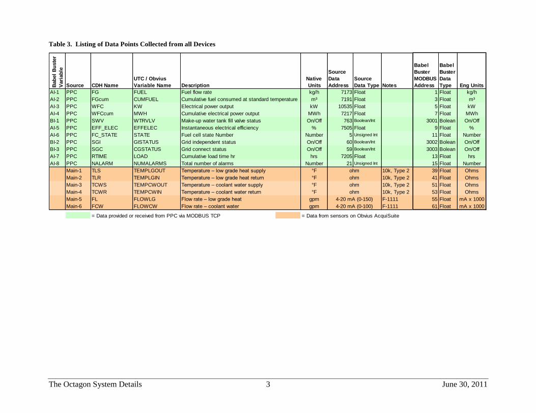
Table 3. Listing of Data Points Collected from all Devices
Bab
el
Bu
ste
r
Vari
ab
le
Source CDH Name
UTC / Obvius
Variable Name
Native
Units
Source
Data
Address
Source
Data Type Notes
Babel
Buster
MODBUS
Address
Babel
Buster
Data
Type Eng Units
AI-1 PPC FG FUEL kg/h 7173 Float 1 Float kg/h
AI-2 PPC FGcum CUMFUEL m³ 7191 Float 3 Float m³
AI-3 PPC WFC KW kW 10535 Float 5 Float kW
AI-4 PPC WFCcum MWH MWh 7217 Float 7 Float MWh
BI-1 PPC SWV WTRVLV On/Off 763 Boolean/Int 3001 Bolean On/Off
AI-5 PPC EFF_ELEC EFFELEC % 7505 Float 9 Float %
AI-6 PPC FC_STATE STATE Number 5 Unsigned Int 11 Float Number
BI-2 PPC SGI GISTATUS On/Off 60 Boolean/Int 3002 Bolean On/Off
BI-3 PPC SGC CGSTATUS On/Off 59 Boolean/Int 3003 Bolean On/Off
AI-7 PPC RTIME LOAD hrs 7205 Float 13 Float hrs
AI-8 PPC NALARM NUMALARMS Number 21 Unsigned Int 15 Float Number
Main-1 TLS TEMPLGOUT °F 10k, Type 2 39 Float Ohms
Main-2 TLR TEMPLGIN °F 10k, Type 2 41 Float Ohms
Main-3 TCWS TEMPCWOUT °F 10k, Type 2 51 Float Ohms
Main-4 TCWR TEMPCWIN °F 10k, Type 2 53 Float Ohms
Main-5 FL FLOWLG gpm F-1111 55 Float mA x 1000
Main-6 FCW FLOWCW gpm F-1111 61 Float mA x 1000Flow rate – coolant water
Temperature – low grade heat return
Temperature – low grade heat supply
Temperature – coolant water return
Fuel cell state Number
Grid independent status
Grid connect status
Cumulative load time hr
Temperature – coolant water supply
Flow rate – low grade heat
= Data provided or received from PPC via MODBUS TCP = Data from sensors on Obvius AcquiSuite
Description
Fuel flow rate
Cumulative fuel consumed at standard temperature
Electrical power output
Cumulative electrical power output
Make-up water tank fill valve status
Instantaneous electrical efficiency
Total number of alarms
4-20 mA (0-150)
ohm
ohm
ohm
ohm
4-20 mA (0-100)

The Octagon System Details 4 June 30, 2011
Babel Buster XML File <?xml version="1.0" encoding="ISO-8859-1"?>
<!-- Babel Buster BB2-7010 v2.10 configuration file -->
<configuration>
<modbus_devices>
<dev id="1" ipaddr="192.168.0.10" unit="1" rate="1.000000" name="UTC PPC" swapped="1"/>
<dev id="2" ipaddr="192.168.0.220" unit="250" rate="1.000000" name="Acquisuite Main Board"/>
</modbus_devices>
<client_read>
<rule localreg="1" remtype="hold_reg" remreg="7173" remfmt="float" dev="1" scale="0.000000" offset="0.000000" poll="1.00" name="FUEL"/>
<rule localreg="2" remtype="hold_reg" remreg="7191" remfmt="float" dev="1" scale="0.000000" offset="0.000000" poll="1.00" name="CUMFUEL"/>
<rule localreg="3" remtype="hold_reg" remreg="10535" remfmt="float" dev="1" scale="0.000000" offset="0.000000" poll="1.00" name="KW"/>
<rule localreg="4" remtype="hold_reg" remreg="7217" remfmt="float" dev="1" scale="0.000000" offset="0.000000" poll="1.00" name="MWH"/>
<rule localreg="3001" remtype="coil" remreg="763" remfmt="int" dev="1" scale="0.000000" offset="0.000000" poll="1.00" name="WTRVLV"/>
<rule localreg="5" remtype="hold_reg" remreg="7505" remfmt="float" dev="1" scale="0.000000" offset="0.000000" poll="1.00" name="EFFELEC"/>
<rule localreg="6" remtype="hold_reg" remreg="5" remfmt="uint" dev="1" scale="0.000000" offset="0.000000" poll="1.00" name="STATE"/>
<rule localreg="3002" remtype="coil" remreg="60" remfmt="int" dev="1" scale="0.000000" offset="0.000000" poll="1.00" name="GISTATUS"/>
<rule localreg="3003" remtype="coil" remreg="59" remfmt="int" dev="1" scale="0.000000" offset="0.000000" poll="1.00" name="CGSTATUS"/>
<rule localreg="7" remtype="hold_reg" remreg="7205" remfmt="float" dev="1" scale="0.000000" offset="0.000000" poll="1.00" name="LOAD"/>
<rule localreg="8" remtype="hold_reg" remreg="21" remfmt="uint" dev="1" scale="0.000000" offset="0.000000" poll="1.00" name="NUMALARMS"/>
<rule localreg="12" remtype="hold_reg" remreg="13" remfmt="uint" dev="1" scale="0.000000" offset="0.000000" poll="1.00" name="ISTATE"/>
<rule localreg="20" remtype="hold_reg" remreg="1" remfmt="double" dev="2" scale="0.000000" offset="0.000000" poll="1.00" name="Acquisuite TLS"/>
<rule localreg="21" remtype="hold_reg" remreg="3" remfmt="double" dev="2" scale="0.000000" offset="0.000000" poll="1.00" name="Acquisuite TLR"/>
<rule localreg="26" remtype="hold_reg" remreg="5" remfmt="double" dev="2" scale="0.000000" offset="0.000000" poll="1.00" name="Acquisuite TCWS"/>
<rule localreg="27" remtype="hold_reg" remreg="7" remfmt="double" dev="2" scale="0.000000" offset="0.000000" poll="1.00" name="Acquisuite TCWR"/>
<rule localreg="28" remtype="hold_reg" remreg="9" remfmt="double" dev="2" scale="0.000000" offset="0.000000" poll="1.00" name="Acquisuite FL"/>
<rule localreg="31" remtype="hold_reg" remreg="11" remfmt="double" dev="2" scale="0.000000" offset="0.000000" poll="1.00" name="Acquisuite FCW"/>
</client_read>
<client_write>
</client_write>
<rtu_read>
<rule localreg="9" remtype="hold_reg" remreg="1100" remfmt="double" unit="1" scale="0.000000" offset="0.000000" poll="0.00" name="MWHREC_pos"/>
<rule localreg="10" remtype="hold_reg" remreg="1102" remfmt="double" unit="1" scale="0.000000" offset="0.000000" poll="0.00" name="MWHREC_neg"/>
<rule localreg="11" remtype="hold_reg" remreg="900" remfmt="float" unit="1" scale="0.000000" offset="0.000000" poll="0.00" name="KWREC"/>
</rtu_read>
<rtu_write>
</rtu_write>
<rtu_device>
<dev baud="9600" slave="1" unit="2"/>
</rtu_device>
<bip_devices>
</bip_devices>
<bipclient_read>
</bipclient_read>
<bipclient_write>
</bipclient_write>
</configuration>

The Octagon System Details 5 June 30, 2011
Table 4. Sensor and Wiring Details for AcquiSuite
Channel /
Source Data Pt Description Instrument / Meter
Signal /
Register Eng Units Wire Notes
Main-1 TLS Low Temp Supply Temp (from FC) 10k Thermistor, Type 2 ohm °F 43
Main-2 TLR Low Temp Return Temp (to FC) 10k Thermistor, Type 2 ohm °F 42
Main-3 TCWS Cooling Water Supply Temp (from FC) 10k Thermistor, Type 2 ohm °F 35
Main-4 TCWR Cooling Water Return Temp (to FC) 10k Thermistor, Type 2 ohm °F 36
Main-5 FL Low Temp Water Flow Onicon F1100 4-20 mA gpm 44, 45 3 inch, sched 40 steel, 100 gpm
Main-6 FCW Cooling Water Flow Onicon F1100 4-20 mA gpm 37, 38 2 inch, sched 40 copper, 60 gpm
Modbus TCP FG Instantaneous Fuel Flow PPC 7173 kg/h Float page 12 of FCFR
Modbus TCP FGcum Cumulative Fuel Consumption PPC 7191 m³ Float page 12 of FCFR
Modbus TCP WFC Instantaneous Power Output PPC 10535 kW Float page 12 of FCFR
Modbus TCP WFCcum Cumulative Power Produced PPC 7217 MWh Float page 12 of FCFR
Modbus TCP EFF_ELEC Instantaneous electrical efficiency (LHV) PPC 7505 % Float page 12 of FCFR
Modbus TCP FC_STATE Fuel Cell Mode/State Number PPC 5 Number Unsigned Int page 12 of FCFR
Modbus TCP RTIME Cumulative "Load" Time PPC 7205 hrs Float page 12 of FCFR
Modbus TCP NALARM Total number of alarms PPC 21 Number Unsigned Int page 12 of FCFR
Modbus TCP SWV Make-up water tank fill valve status PPC 763 On/Off Boolean/Int page 12 of FCFR
Modbus TCP SGI Grid independent status PPC 60 On/Off Boolean/Int page 12 of FCFR
Modbus TCP SGC Grid connect status PPC 59 On/Off Boolean/Int page 12 of FCFR
Table 5. Forwarded Addresses on Digi Modem

The Octagon System Details 6 June 30, 2011
Obvius AcquiSuite
The AcquiSuite data logger produces a separate file of 1-minute data for each device. The read
map for the data logger is given below.
Chan Name Device Column
FG, mb-001, 0
FGCUM, mb-001, 1
WFC, mb-001, 2
WFCCUM, mb-001, 3
SWV, mb-001, 4
EFF_ELEC, mb-001, 5
FC_STATE, mb-001, 6
SGI, mb-001, 7
SGC, mb-001, 8
RTIME, mb-001, 9
NALARM, mb-001, 10
ISTATE, mb-001, 16
TLS, mb-250, 1
TLR, mb-250, 6
TCWS, mb-250, 11
TCWR, mb-250, 16
FL, mb-250, 21
FCW, mb-250, 26
Notes: mb-001 – MODBUS Reads
mb-250 – AcquiSuite Main Board
Sensor Calibrations:
Thermistor # Name Wire Input Channel Mult Offset
32 TLS 43 Main-4 0.98596 -0.19
31 TLR 42 Main-5 0.98722 0.07
6-35 TCWS 35 Main-6 0.98580 -0.20
6-36 TCWR 36 Main-7 0.98643 -0.10