Embed Size (px)
Citation preview

Wh
eel
Ser
vice
Ma
nu
al
for trucks, trailers, and buses
January 2000
Wh
eel
Ser
vice
Ma
nu
al

LIMITEDWARRANTY
FOR HEAVY DUTY TRUCKS,TRUCK TRAILERS AND BUSES
(Wheels with bead seat diameters measured in .5 inchincrements and Alcoa tube type wheels)
Alcoa warrants to the original purchaser from Alcoa or itsauthorized distributor that a new Alcoa aluminum disc heavyduty truck, truck trailer or bus wheel is free from defects inmaterial and workmanship. Alcoa agrees, without charge, torepair or replace a wheel which fails in normal use and ser-vice because of defects in material or workmanship. Wheelsare warranted for 60 months from date of manufacture asshown on the wheel. Alcoa bus mount wheels (10-hole,11.25 inch bolt circle, 8.670 inch hub bore with 1.22 inchdiameter bolt holes) used in transit service are warranted for120 months from date of manufacture. Alcoa does not war-rant and will not repair or replace or make adjustment withrespect to normal wear or for any wheel which has beendamaged or subjected to misuse or abuse including, withoutlimitation, the following:
(a) Using a tire which is improperly sized according tostandards recommended by Alcoa or the Tire and RimAssociation, Inc.
(b) Loading beyond the applicable maximum wheel load asspecified by Alcoa;
(c) Inflating beyond the applicable maximum as specified byAlcoa;
(d) Changing the original condition of the wheel by alterationor by subjecting it to processing, such as heating, welding,straightening or machining;
(e) Accidents, abnormal or severe operating conditions; or
(f) Failure to follow recommended maintenance on the wheelas set forth in Alcoa's Heavy Duty Wheel Service Manual,Alcoa Technical Bulletins and other Alcoa literature.Recommended maintenance includes, without limitation,periodic cleaning, polishing, valve replacement, and rimflange wear inspections and procedures.
THERE IS NO WARRANTY THAT THE WHEEL SHALL BEMERCHANTABLE OR SATISFACTORY FOR ANY PARTICU-LAR PURPOSE. NOR IS THERE ANY OTHER WARRANTY,EXPRESSED OR IMPLIED, ON THE WHEEL.
ALCOA SHALL NOT BE LIABLE FOR ANY INCIDENTALOR CONSEQUENTIAL DAMAGES FOR ANY BREACH OFWARRANTY, ITS LIABILITY AND THE PURCHASER'SEXCLUSIVE REMEDY BEING EXPRESSLY LIMITED TOREPAIR OR REPLACEMENT OF THE WHEEL. Repair orreplacement will be handled by any authorized Alcoawheel distributor or by any Alcoa wheel representativeunder Alcoa's return policy. This warranty gives you spe-cific legal rights. You may also have other rights underother applicable laws.
This warranty should be used in conjunction with Alcoa'sHeavy Duty Wheel Service Manual. It is included with theService Manual, but may appear elsewhere. If you do nothave a copy of the Service Manual you may obtain one alongwith other specification literature by contacting Alcoa WheelProducts International at (800) 242-9898 or the addressbelow.
Alcoa Inc.Wheel Products International
1600 Harvard Avenue, Cleveland, OH 44105
How to use this manual
This manual is written in a style called structured text.
Throughout the manual you will find numbers which looklike this (See 3-1, page 12). These numbers are cross ref-erences to other sections of the manual. The numbers (3-1) refer to section 3, subtopic 1. When you turn to page12 you will find the section number and subtopic numberunder the heading in each section as shown here.
Recommendationsfor mountingtubeless tires.
3-1The cross references will help you find related informationin the manual. For example in section 4-1 you will readthe following sentence...
"Make sure all wheel cap nuts are properlytorqued–check them often (see 4-9, page 20)."
By turning to section 4, subtopic 9, on page 20 you willfind information on proper torquing.
Note: The Alcoa Heavy Duty Wheel Service Manualcontains information for proper service and operation ofAlcoa heavy duty wheels. Alcoa heavy duty wheels forheavy duty trucks, truck trailers and buses are Alcoatubeless wheels with bead seat diameters measured in .5inch increments and Alcoa tube type wheels.

Table of Contents
▼ Section Number Page Number ▼
1 Wheel Specifications..........................................................................................12 Inspection ...........................................................................................................3
2-1 Inspect thoroughly and frequently ..........................................................................................32-2 Dimension checks ...................................................................................................................42-3 Mounting area..........................................................................................................................62-4 Corrosion .................................................................................................................................72-5 Stud holes................................................................................................................................82-6 Disc area..................................................................................................................................82-7 Rim area...................................................................................................................................92-8 Rim flange wear.......................................................................................................................92-9 Gutter area.............................................................................................................................10
3 Alcoa 15° Drop Center for Tubeless Tires ......................................................113-1 Recommendations for mounting tubeless tires....................................................................113-2 Mounting tubeless tires .........................................................................................................123-3 Rim width to tire matching ....................................................................................................133-4 Recommendations for demounting tubeless tires................................................................143-5 Demounting of tubeless tires ................................................................................................14
4 Wheel Installation .............................................................................................154-1 Recommendations for proper installation of wheels ............................................................154-2 Wheel cap nuts......................................................................................................................154-3 How to measure stud standout.............................................................................................164-4 Stud located ball seats are spherical....................................................................................174-5 Single wheel, stud located, ball seat mounting....................................................................174-6 Dualed wheels, stud located, ball seat mounting ................................................................174-7 Dualed wheels, inner steel/outer aluminum stud located, ball seat mounting....................194-8 Cap nut thread engagement, stud located wheels, ball seat mounting..............................204-9 Tightening stud located, ball seat cap nuts..........................................................................204-10 Single, dualed and wide base wheels, hub piloted mounting, two-piece flange nuts........224-11 Tightening hub piloted mounting, two-piece flange nuts.....................................................234-12 Incorrect assemblies .............................................................................................................25
5 Care and Maintenance .....................................................................................265-1 Avoid abuse ...........................................................................................................................265-2 Keep wheel nuts tight............................................................................................................265-3 Lead balance weights (clip on) .............................................................................................265-4 Do not straighten wheels ......................................................................................................265-5 Owner/in-service identification ..............................................................................................275-6 Valves.....................................................................................................................................275-7 Maintenance against corrosion.............................................................................................275-8 Identification...........................................................................................................................28
6 Flat Base Wheel for Tube-type Tires ...............................................................296-1 Tube-type wheel part interchangeability ...............................................................................296-2 Mounting recommendations for tubed tires .........................................................................306-3 Mounting of tubed tires .........................................................................................................316-4 Demounting recommendations for tubed tires.....................................................................326-5 Demounting of tubed tires.....................................................................................................32
7 OSHA Regulations............................................................................................337-1 OSHA Regulations.................................................................................................................33
8 Glossary of Common Terms ............................................................................398-1 Glossary of Common Terms..................................................................................................398-2 Wheel measurement..............................................................................................................41
9 Conversion Tables............................................................................................429-1 Inch Fraction, Decimal and Millimeter Equivalents Chart (Up to 1 Inch).............................429-2 Conversion Formulas ............................................................................................................43
1
2
3
4
5
6
7
8
9
1
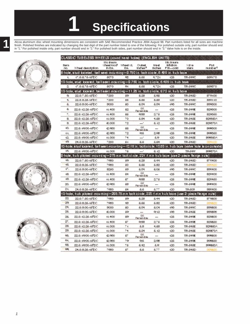
1 SpecificationsAlcoa aluminum disc wheel mounting dimensions are consistent with SAE Recommended Practice J694 August 98. Part numbers listed for all sizes are machinefinish. Polished finishes are indicated by changing the last digit of the part number listed to one of the following: For polished outside only, part number should endin "1." For polished inside only, part number should end in "2." For polished both sides, part number should end in "3." Valve hole is on the inside.1

2
1

3
2 Inspection
Safe operation requires thorough examination of wheels, both on and off thevehicle, and attachment hardware at frequent intervals.
Wheels that have been in service need to be inspected at regularintervals to assure proper and safe performance.
Like tires and other vehicle components that work hard, wheels will eventually wearout. It isn't always possible to predict exactly when the useful life of a wheel will end.But generally, older wheels and wheels operating in extreme conditions should beexamined more frequently for obvious signs that they should be removed fromservice.
As an aid to the owner in determining the period of time a wheel has been in ser-vice, it is recommended the owner stamp an "in service" date onto the wheel at thetime he receives it. See 5-5, page 27 for recommended stamping locations.
Pay particular attention to front-end assemblies. Examine all exposed areas fre-quently. Clean wheels and look for cracks or other damage. Also check the innerdualed wheel when the outer wheel is removed.
During tire changes, thoroughly examine the entire wheel. Pay particular attentionto the rim contour and the surfaces of the rim. On tube-type wheels, carefullyinspect the gutter area normally concealed by the side rings.
Be sure that the best wheels are on the front of the vehicle.
Hidden damage
Some forms of wheel damage can be hidden beneath the tire, so whenever a tireis removed, thoroughly examine the complete wheel. Remove all grease and roaddirt. Use a wire brush or steel wool to remove rubber from the bead seats.
Check mounting holes for the enlargement and elongation which can occur if thecap nuts are not kept tight (see 2-5, page 8). Dirt streaks radiating from stud holesmay mean that the cap nuts are loose (see 4-9, page 20).
Inspectthoroughlyand frequently
2-1
2

4
Dimensionchecks
2-2
Open side circumference check
Warning Wheels that have been subjected to a high pressure tire and rimseparation (or other abuse) may no longer have sufficient dimension andcontour to retain tire bead while under pressure.
Rims which lack proper dimension and contour can lead to explosiveseparation of tire and rim, causing injury or death.
Follow dimension check procedures described in this section during eachwheel inspection. Remove any substandard wheel from service.
WARNING
The circumference of the bead seat on the open side of the wheel should bechecked with each tire change. The open side is the side opposite the disc face.In the case of center flange wide base wheels, or wheels with Insets less than 3inches, both rim flanges should be checked. Measure the circumference of thebead seat on the open side (see illustration below) with a ball tape. Ball tapesused for measuring wheel circumference can be purchased from the Tire andRim Association, Inc., 175 Montrose West Avenue, Copley, Ohio 44321.
If the circumference of the bead seat does not match the required dimension asindicated by the ball tape, remove the wheel from service. Be sure to clearly markthe wheel as out-of-service or otherwise render the wheel unusable.
Continued on the next page
2

5
Dimensionchecks (continued)
Tire wear or ride problems
If you experience tire wear or ride problems it may be helpful to check radial run out.Remove the wheel from the vehicle, deflate and remove the tire (see 3-5, page 14 forrecommendations and instructions for demounting tubeless tires and 6-5, page 32 forrecommendations and instructions for demounting tube-type tires).
Remount the wheel on the vehicle without the tire. Be sure to follow proper mountingprocedures to assure the wheel is well centered on the hub. Place a dial indicator asillustrated below to trace the bead seats of the wheel. Rotate the wheel noting the amountof variation shown on the dial indicator. Note: Alcoa aluminum wheels should be testedfor radial run out only at the bead seat surface. A total indicator reading of .045 inches isacceptable.
Tire wear can also be caused by improperly seated tires. Inspect the tire for proper seat-ing on the wheel. The tire beads may not be seated properly. If so, remove the wheel fromthe vehicle, deflate and break the bead seats (see 3-5, page 14 for recommendations andinstructions for demounting tubeless tires and 6-5, page 32 for recommendations andinstructions for demounting tube-type tires). Adequately lubricate the bead seats andproperly reseat the tire beads. Reinflate the wheel in a safety cage or other suitablerestraint (refer to OSHA rule 1910.177, paragraph b, see Section 7, page 33).
2

6
Mounting area
2-3
Stud hole cracks are usually caused by improper torquing (see 4-9, page 20 and 5-2, page26), excessive loading or insufficient mounting flange support by the hub or brake drum.Remove wheel from service.
Shown below are stud hole cracks emanating from stud hole to stud hole. Causes are:undersized diameter of wheel support surface (see specifications below), support surfacenot flat, incorrect attachment parts (see 4-12, page 25) and insufficient torque (see 4-9,page 20 and 5-2, page 26). Remove wheel from service.
Support surface should be flat to the diameter recommended on the chart on the follow-ing page.
Inspect the hub/drum con-tact area thoroughly forcracks or other damage.
2

7
Mounting area(continued)
Support surface diameters
Support surface (backup diameter) should be flat to the diameter recommendedon the chart below:
Number of Bolts Bolt Circle Mounting Type Backup Diameter Thread Size
10 11.25 inch U.S. Stud pilot 13.2-13.5 in. .750/1.125 in.
10 285.75mm Hub pilot 13.2-13.4 in. 22mm
10 335mm Hub pilot 15.0-15.2 in. 22mm
8 275mm U.S. Stud pilot 13.2-13.5 in. 22mm
8 275mm ISO Hub pilot 12.4-12.6 in. 20mm
Corrosion
2-4
Due to aluminum's natural resistance to corrosion, Alcoa aluminum disc wheelsdo not need to be painted for most operating conditions. However, certain envi-ronments can lead to corrosion. Some of these are: salt, chloride compoundsused for snow removal and highly alkaline materials. If the air used to fill tubelesstires, or the tire itself, is not dry, the areas of the wheel under the tire can corrodeseverely.
Bead seat and valve stem corrosion often are caused by entrapped moisturewhich contains corrosive elements. Mild corrosion should be removed thorough-ly by wire brush and the rim protected with a coating of non-water-based lubricant(see 3-1, page 11). Remove any severely corroded wheel from service.
2

8
Stud holes
2-5
If wheels are run loose, both stud located wheels and hub piloted wheels can bedamaged. Look for wallowed out or elongated ball seats on stud located wheels.On hub piloted wheels look for elongated stud holes. Over torquing can lead todamaged ball seats on stud located wheels and can damage the disc surface ofhub piloted wheels. Remove damaged wheels from service.
Damages hub piloted bolt hole.Elongation from true round (dashed cir-cle) indicated by arrows.
Damaged ball seat contact area.Pounding of stud on ball seat contactarea identified by arrows.
Disc area
2-6
Inspect both sides of disc area for hand hole cracks. If cracks are found, removewheel from service.
2
9
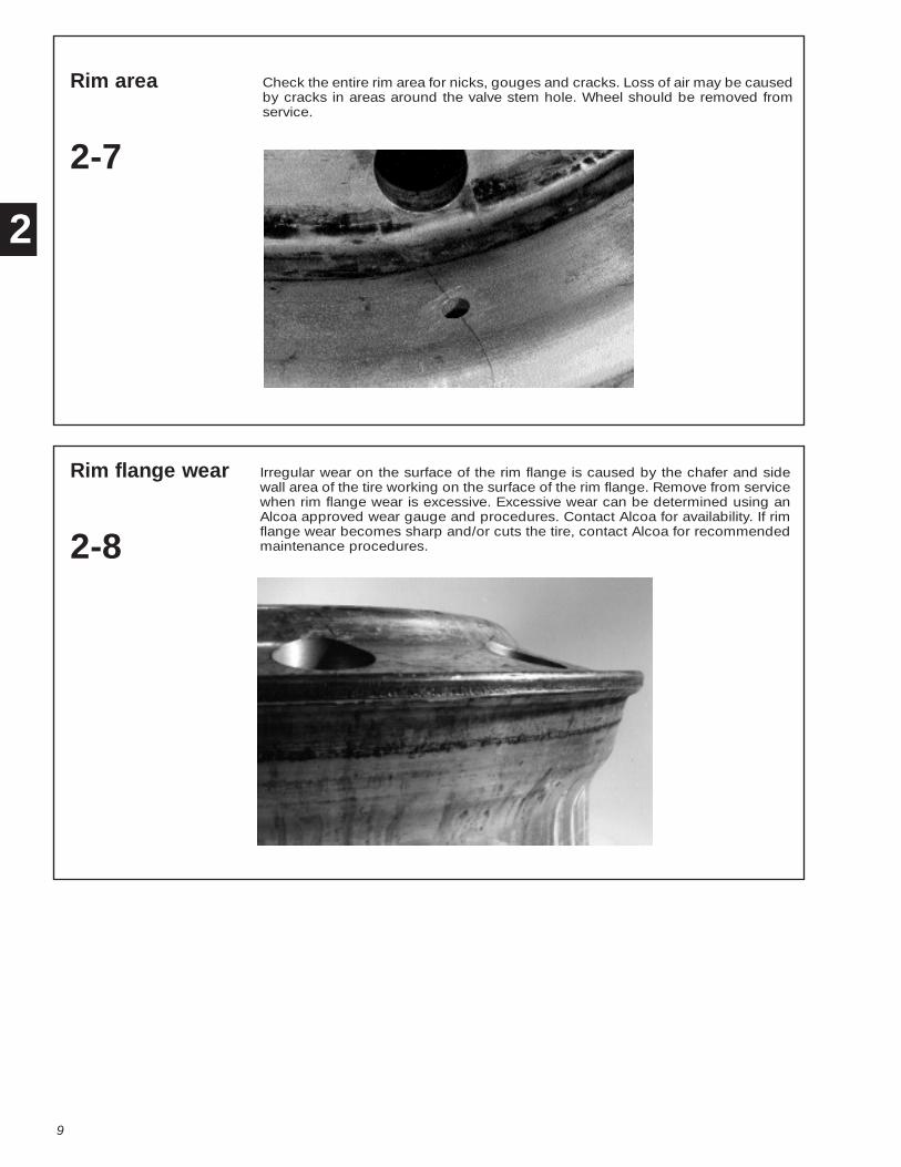
Rim area
2-7
Check the entire rim area for nicks, gouges and cracks. Loss of air may be causedby cracks in areas around the valve stem hole. Wheel should be removed fromservice.
Rim flange wear
2-8
Irregular wear on the surface of the rim flange is caused by the chafer and sidewall area of the tire working on the surface of the rim flange. Remove from servicewhen rim flange wear is excessive. Excessive wear can be determined using anAlcoa approved wear gauge and procedures. Contact Alcoa for availability. If rimflange wear becomes sharp and/or cuts the tire, contact Alcoa for recommendedmaintenance procedures.
2

10
Gutter area
2-9
Projections on the side of the wheel gutter area can cause uneven seating of theside and lock ring and chipping of the gutter. Such projections must be removed.Remove wheel from service if damaged.
Cracking in bottom of gutter flange. Occasionally, circumferential cracks mayappear in the bottom of the gutter area. This area should be thoroughly cleanedand carefully inspected after a tire is removed from the wheel. Also check the sideunderneath gutter flange for circumferential cracks. Gutter flange cracks can ulti-mately lead to the separation of the rim area from the disc. Immediately removefrom service a wheel that exhibits any cracks.
2

WARNING Use of a volatile or flammable material, such as ether or gasoline,as an aid to seating the tire beads on the wheel can lead to an uncontrolledpressure build-up in the tire and may result in an explosion.
Explosive separation of the tire and wheel can occur while seating beads inthis manner, while adding air to the tire or later on the road. Loss of vehiclecontrol can result, which can cause serious injury or death.
Use only approved mechanical or pneumatic bead seating devices.
11
Alcoa 15° Drop Center Wheel3 for Tubeless Tires
Recommendationsfor mountingtubeless tires
3-1
WARNING Use of inner tubes in tubeless wheels will hide slow leaks. Slow leaksmay indicate cracked or damaged wheels which lead to wheel failures.
Wheel failures can cause accidents which may result in serious injury or death.
Never use an inner tube on an Alcoa tubeless wheel, and always remove crackedor damaged wheels from service.
WARNING A pressurized tire/wheel assembly can explode and separateviolently.
This violent separation can cause serious injury or death.
Always contain the tire/wheel assembly in an inflation cage during inflation.
WARNING
WARNING
WARNING
NOTICE: For completeinformation on tube typewheels, contact Alcoa.
NOTICE: Alcoa aluminum19.5”RW and non-symetricalwell wide base wheelsrequire special tire mountingtechniques, See Section 3-2.
3 1. Do not gouge or nick the wheel. Place aluminum wheels on a clean wooden floor orrubber mat when hand mounting tires.2. Always use a rubber, leather-faced or plastic mallet.3. Inspect the wheel for damage. Do not use a damaged or severely corroded wheel.(See Section 2, page 3.)4. Clean the wheel face with mild detergent and the tire bead seat areas with a wirebrush. Be sure the wheel is dry before applying tire lubricant.5. Inspect the tire for damage. Be sure the inside of the tire is dry before it is mounted.6. Use of a non-water-based lubricant is recommended as a rim surface protectant andtire mounting lubricant. Coat the entire rim surface. (See 3-2, page 12).7. Lubricate the rim and tire bead immediately before mounting the tire. Do not use anylubricant which contains water. Water-based lubricants can promote corrosion attack onthe rim surface. The use of non-water-based lubricants is especially important whenmounting tubeless tires as the air in the tire is contained by the seal between the beadand tire rim.8. Never lubricate the rim or tire bead with a flammable solution. This can lead to anexplosion during airing of the tire or in subsequent operation of the vehicle (see Warningbelow).9. If using a tire mounting/demounting machine on aluminum wheels, care should betaken to prevent gouging the wheel.10. Use only dry air for tire inflation. The use of moisture traps in the air compressor feedline is recommended.11. Do not overinflate. Use the tire manufacturer’s recommended pressure, but under nocircumstances exceed cold tire pressures listed in Section 1 Specifications of this manu-al (see page 1).12. When inflating a tire in an inflation cage or while mounted on a vehicle, always use aclip-on air chuck or threaded straight chuck and a remote valve with pressure gauge.Securely anchor the inflation cage and during inflation or handling of an inflated wheeland tire assembly, stay out of the path of potential exploding parts or air blasts.
12
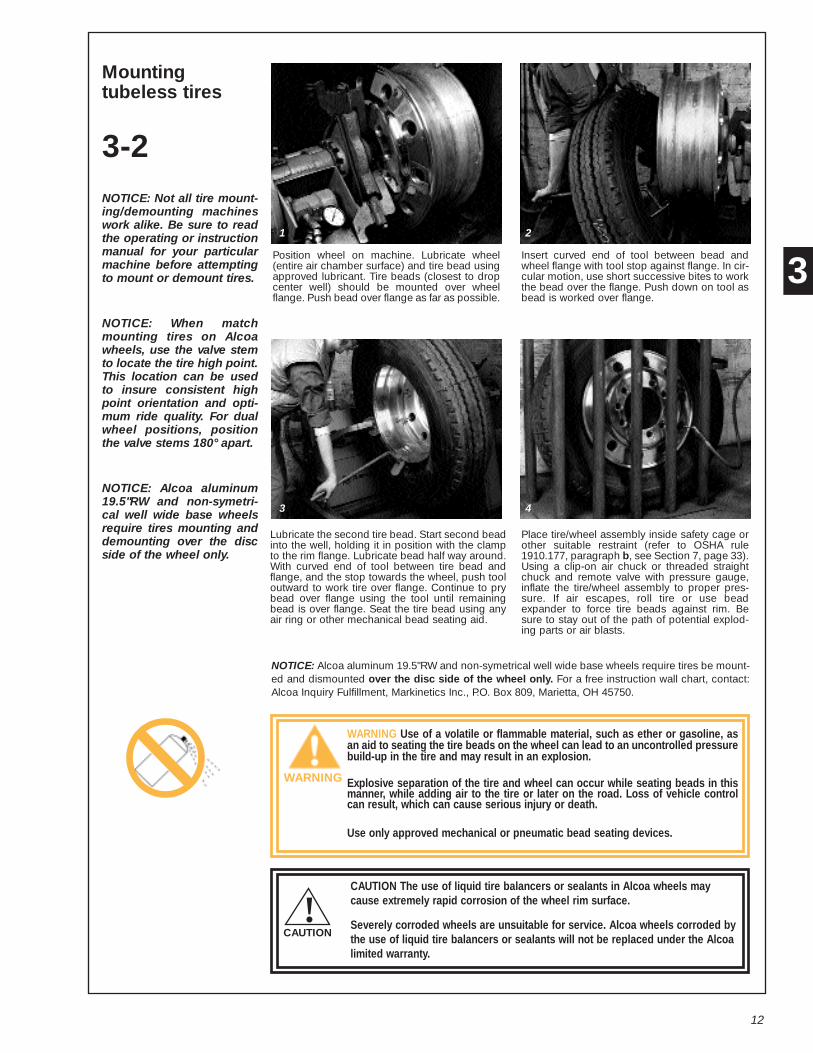
Mountingtubeless tires
3-2NOTICE: Not all tire mount-ing/demounting machineswork alike. Be sure to readthe operating or instructionmanual for your particularmachine before attemptingto mount or demount tires.
NOTICE: When matchmounting tires on Alcoawheels, use the valve stemto locate the tire high point.This location can be usedto insure consistent highpoint orientation and opti-mum ride quality. For dualwheel positions, positionthe valve stems 180° apart.
NOTICE: Alcoa aluminum19.5"RW and non-symetri-cal well wide base wheelsrequire tires mounting anddemounting over the discside of the wheel only.
Position wheel on machine. Lubricate wheel(entire air chamber surface) and tire bead usingapproved lubricant. Tire beads (closest to dropcenter well) should be mounted over wheelflange. Push bead over flange as far as possible.
Insert curved end of tool between bead andwheel flange with tool stop against flange. In cir-cular motion, use short successive bites to workthe bead over the flange. Push down on tool asbead is worked over flange.
Lubricate the second tire bead. Start second beadinto the well, holding it in position with the clampto the rim flange. Lubricate bead half way around.With curved end of tool between tire bead andflange, and the stop towards the wheel, push tooloutward to work tire over flange. Continue to prybead over flange using the tool until remainingbead is over flange. Seat the tire bead using anyair ring or other mechanical bead seating aid.
Place tire/wheel assembly inside safety cage orother suitable restraint (refer to OSHA rule1910.177, paragraph b, see Section 7, page 33).Using a clip-on air chuck or threaded straightchuck and remote valve with pressure gauge,inflate the tire/wheel assembly to proper pres-sure. If air escapes, roll tire or use beadexpander to force tire beads against rim. Besure to stay out of the path of potential explod-ing parts or air blasts.
NOTICE: Alcoa aluminum 19.5"RW and non-symetrical well wide base wheels require tires be mount-ed and dismounted over the disc side of the wheel only. For a free instruction wall chart, contact:Alcoa Inquiry Fulfillment, Markinetics Inc., P.O. Box 809, Marietta, OH 45750.
WARNING Use of a volatile or flammable material, such as ether or gasoline, asan aid to seating the tire beads on the wheel can lead to an uncontrolled pressurebuild-up in the tire and may result in an explosion.
Explosive separation of the tire and wheel can occur while seating beads in thismanner, while adding air to the tire or later on the road. Loss of vehicle controlcan result, which can cause serious injury or death.
Use only approved mechanical or pneumatic bead seating devices.
CAUTION The use of liquid tire balancers or sealants in Alcoa wheels maycause extremely rapid corrosion of the wheel rim surface.
Severely corroded wheels are unsuitable for service. Alcoa wheels corroded bythe use of liquid tire balancers or sealants will not be replaced under the Alcoalimited warranty.
CAUTION
WARNING
!
31
3
2
4
13
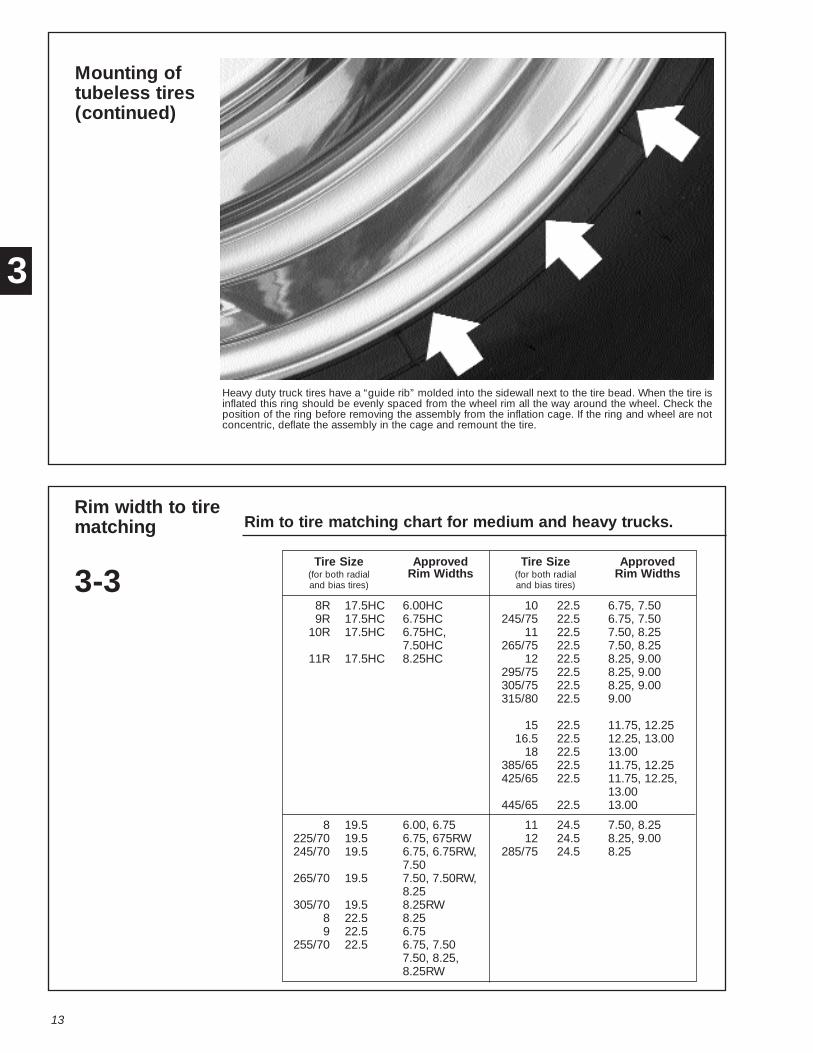
Mounting oftubeless tires(continued)
Heavy duty truck tires have a “guide rib” molded into the sidewall next to the tire bead. When the tire isinflated this ring should be evenly spaced from the wheel rim all the way around the wheel. Check theposition of the ring before removing the assembly from the inflation cage. If the ring and wheel are notconcentric, deflate the assembly in the cage and remount the tire.
Rim width to tirematching
3-3
Rim to tire matching chart for medium and heavy trucks.
Tire Size Approved Tire Size Approved(for both radial Rim Widths (for both radial Rim Widthsand bias tires) and bias tires)
8R 17.5HC 6.00HC 10 22.5 6.75, 7.509R 17.5HC 6.75HC 245/75 22.5 6.75, 7.50
10R 17.5HC 6.75HC, 11 22.5 7.50, 8.257.50HC 265/75 22.5 7.50, 8.25
11R 17.5HC 8.25HC 12 22.5 8.25, 9.00295/75 22.5 8.25, 9.00305/75 22.5 8.25, 9.00315/80 22.5 9.00
15 22.5 11.75, 12.2516.5 22.5 12.25, 13.00
18 22.5 13.00385/65 22.5 11.75, 12.25425/65 22.5 11.75, 12.25,
13.00445/65 22.5 13.00
8 19.5 6.00, 6.75 11 24.5 7.50, 8.25225/70 19.5 6.75, 675RW 12 24.5 8.25, 9.00245/70 19.5 6.75, 6.75RW, 285/75 24.5 8.25
7.50265/70 19.5 7.50, 7.50RW,
8.25305/70 19.5 8.25RW
8 22.5 8.259 22.5 6.75
255/70 22.5 6.75, 7.507.50, 8.25,8.25RW
3
14
Recommendationsfor demountingtubeless tires
3-4
WARNING Damaged tires or wheels can lead to an explosive sepa-ration of tires and wheels.Explosive separation can result in serious injury or death.Inspect tires and wheels for damage before removing from vehicle.If damage is found, tire must be completely deflated before loosen-ing cap nuts. Remove damaged tires or wheels from service.
1. When hand demounting tires from wheels, placing aluminum wheels on a clean woodenfloor or rubber mat is recommended.
2. Always use a rubber, leather-faced or plastic mallet.
3. Keep tire tools smooth. Use them with care. Rim gouges or nicks may cause cracks.
4. If using a tire mounting/demounting machine on aluminum wheels, care should be takento prevent gouging the wheel.
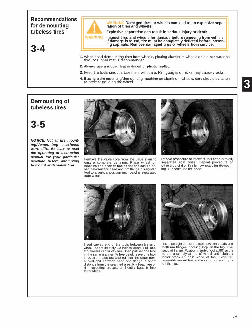
Demounting oftubeless tires
3-5NOTICE: Not all tire mount-ing/demounting machineswork alike. Be sure to readthe operating or instructionmanual for your particularmachine before attemptingto mount or demount tires.
Remove the valve core from the valve stem toensure complete deflation. Place wheel onmachine and position tool so flat end can be dri-ven between tire bead and rim flange. Straightentool to a vertical position until bead is separatedfrom wheel.
Repeat procedure at intervals until bead is totallyseparated from wheel. Repeat procedure onother side of tire. Tire is now ready for demount-ing. Lubricate the tire bead.
Insert curved end of tire tools between tire andwheel, approximately 10 inches apart. Pull onetool toward center of wheel, then pull second toolin the same manner. To free bead, leave one toolin position, take out and reinsert the other tool,curved end between bead and flange, a shortdistance from the spanned area. Pry bead free ofrim, repeating process until entire bead is freefrom wheel.
Insert straight end of tire tool between beads andboth rim flanges, hooking stop on the tool oversecond flange. Position inserted tool at 90° angleto tire assembly at top of wheel and lubricatebead areas on both sided of tool. Lean tireassembly toward tool and rock or bounce to pryoff the tire.
WARNING
3
1
3
2
4

15
4 Wheel Installation
Recommendationsfor properinstallation ofwheels
4-1
1. For the same reason the best tires are run on the front axle, the best wheels also should be used on the front axle.
2. Make sure all wheel cap nuts are properly torqued — check them often (see 4-9, page 20). If thewheel is loose, the holes will pound out (deform). If some cap nuts are tight and others are loose, thewheel may develop cracks or studs may break. Dirt streaks radiating from stud holes can indicateloose nuts (see 2-1, page 3).
3. Be sure the end of the wheel wrench is smooth or cover the wheel mounting surface with a protec-tive shield prior to tightening the cap nuts. The wrench end will mar the wheel around the cap nuts ifit is not smooth.
4. Keep all component contact surfaces smooth and clean. Dirt or projections in mounting area maylead to loose wheels. Remove all projections resulting from burrs, nicks, etc. Be sure that loose dirtdoes not fall into mounting area during assembly.
5. Check for and replace bent, broken, cracked or damaged studs. When replacing broken studs,replace studs on both sides of the broken stud also. If two or more studs are broken, replace all thestuds for that wheel.
6. Do not introduce any foreign objects such as spacers or high hats into the contact surface areas ofthe mounting system unless approved by Alcoa. Do not paint Alcoa forged aluminum wheels.
Wheel cap nuts
4-2
WARNING Use of chrome-plated cap nuts which have chrome plating on thesurfaces which contact the wheel can cause reduced and inconsistent wheelclamping.
This condition can cause wheels to loosen and disengage from the vehicle,causing injury or death.
Never use cap nuts with chrome-plated contact surfaces. Use only recom-mended hardware on Alcoa aluminum wheels.
There are many types of nuts and studs in use, and their design and specifications are notstandardized. Alcoa recommends the following cap nuts for use with Alcoa aluminumtruck wheels:
Cap Nuts
2-piece 33mm hex head flangenut. Mounts single and dualedwheels to wheel centering hubs.Right hand threads used on bothsides of vehicle. Single wheelsrequire 2” (50.8 mm) stud stand-out. Dualed wheels require2-13/16 (71.44 mm) stud stand-out. P/N 39701 (supercedes P/N39691); M22-1.5 RH threads.
2 piece 1-1/16” hex headflange nut. Mounts single anddualed wheels to wheel center-ing hubs. Right hand threadsused in both sides of vehicle.P/N 39946; 5/8”x18 RH threads
2-piece 30mm hex head flangenut. Mounts single and dualedwheels to wheel centering hubs.Right hand threads used on bothsides of vehicle.. P/N 39708;M20x1.5 RH threads.
Continued on next page
WARNING
4

16
Wheel cap nuts(continued)
2-piece 33mm hex head flangenut. Mounts dualed wheels towheel centering hubs with32mm bolt holes. Right handthreads used on both sides ofvehicle. P/N 4307.32; M22x1.5RH threads.
2-piece 33mm hex head flangenut. Mounts single wheels towheel centering hubs with 32mmbolt holes. Right hand threadsused on both sides of vehicle.P/N 4306.32; M22x1.5 RHthreads.
1-1/8" cap nut. Mounts standardsingle wheels and wide basewheels to 1-1/8" studs. Alsomounts outer dualed wheel to1-1/8" inner cap nut. P/N 5996R,5996L (replaces P/N 5552R,5552L).
3/4"x16 cap nut. Mounts Alcoawide base wheels to 3/4" studs.Do not use on steel wheels. P/N5995R, 5995L (replaces P/N5554R, 5554L).
Inner cap nut, innerthread 3/4"x16, outerthread 1-1/8"x16. Foruse with standard lengthstuds (1.31" [1-5/16] to1.44" [1-7/16]) studstand-out) or longerstuds not to exceed
1.88" [1-7/8] stud standout. Full internal and externalthreads. P/N 5978R, 5978L (Grade 8). For studs with-out exposed shoulders. Do not use with steel innerdualed wheel.
Inner cap nut for usewith standard lengthstuds (1.31" [1-5/16] to1.44" [1-7/16]) studstandout) or longerstuds not to exceed 1.88"(1-7/8) stud stand-out.
Full internal and external threads, counter bore 5/16"deep at open end. Prevents stud from bottoming outin cap nut. P/N 5988R, 5988L (Grade 8). For use withstuds with exposed shoulders. Do not use with steelinner dualed wheel.
How to measurestud standout
4-3
Stud standout is measured from the axle end mounting surface to the end of the stud.
Inboard mounted drum Outboard mounted drum
4
Inner cap nut, innerthread 3/4"x16, outerthread 1-1/8"x16. For usewith steel inner dualwheel an aluminum outerdual wheel with 1.31"
(1-5/16) to 1.44" (1-7/16) stud standout.P/N 7896R, 7896L (Grade 8).

17
Stud located ballseat arespherical
4-4
The nut seat for the stud located ball seat mounting system is a precision-machined spherical surface. Cap nuts must be properly manufactured toassure seating. Never use one or two-piece flange cap nuts on a wheeldesigned with ball seats (see 4-12, page 25). Ball seat cap nuts may beobtained from your Alcoa Wheel Distributor.
Single wheel,stud located, ballseat mounting
4-5
Front wheels are mounted as singles and require 1.6" (1-39/64") minimum stud standout.Most vehicles have large 1-1/8-inch bus-type studs on the front hubs. Alcoa single capnuts, Part Nos. 5996R and 5996L, or equivalents, should be used. Some front hubs have3/4-inch studs. On these hubs, use Alcoa single cap nuts, Part Nos. 5995R and 5995L orequivalents.
Alcoa Aluminum Wheel
Alcoa Aluminum Wheel
Correct single mounting with 3/4-inch stud located, ball seat mount.
Correct single mounting with 1-1/8-inch stud located, ball seat mount.
Dualed wheels,stud located, ballseat mounting
4-6
Rear wheels are most frequently mounted as duals. Each inner aluminum wheel isattached by 10 inner cap nuts. Alcoa recommends use of inner cap nuts 5978R, 5978L, or5988R, 5988L (see 4-2, page 15).
Cap nuts recommended by Alcoa are compatible with Alcoa wheels. Hardware of equaldimensions and strength may be used.
Continued on next page.
4

18
Dualed wheels,stud located, ballseat mounting(continued)
Most vehicles have standard length studs (1.31" [1-5/16"] to 1.44" [1-7/16"] stud standout).Some vehicles use studs longer than standard (up to 1.88" [1-7/8"] standout).
When changing types of brake drums be sure to check for excessive stud standout(greater than 1.88" [1-7/8"]). Excessive stud standout may cause the inner cap nut tobottom out on the longer stud preventing proper seating of the wheel.
Each outer dual wheel is attached by 10 single cap nuts which thread on the inner capnuts. Use Alcoa outer cap nuts, Part Nos. 5996R, 5996L or equivalents. Match mounteddual wheels should be put on the vehicles with the valve stems180° apart.
Alcoa Aluminum Wheels
Drum
3/4” Stud
Hub
Outer Cap NutP/N 5996R or L
1.31” a 1.88”
Correct dual mounting with stud located, ball seat mount.
WARNING Incorrect inner cap nuts used with dualed aluminum wheels canbottom out on the unthreaded portion of the stud before the wheels are prop-erly seated.
Improperly seated wheels can run loose, cause stud breakage and disengagefrom the vehicle which can cause serious injury or death. Loose runningwheels can lead to stud breakage.
Use only cap nut 5978R or L, 5988R or L, or their equivalent when mountingdual aluminum wheels.
Inner Cap NutP/N 5978R or L orP/N 5988R or L
4
ADVERTENCIA
WARNING
19
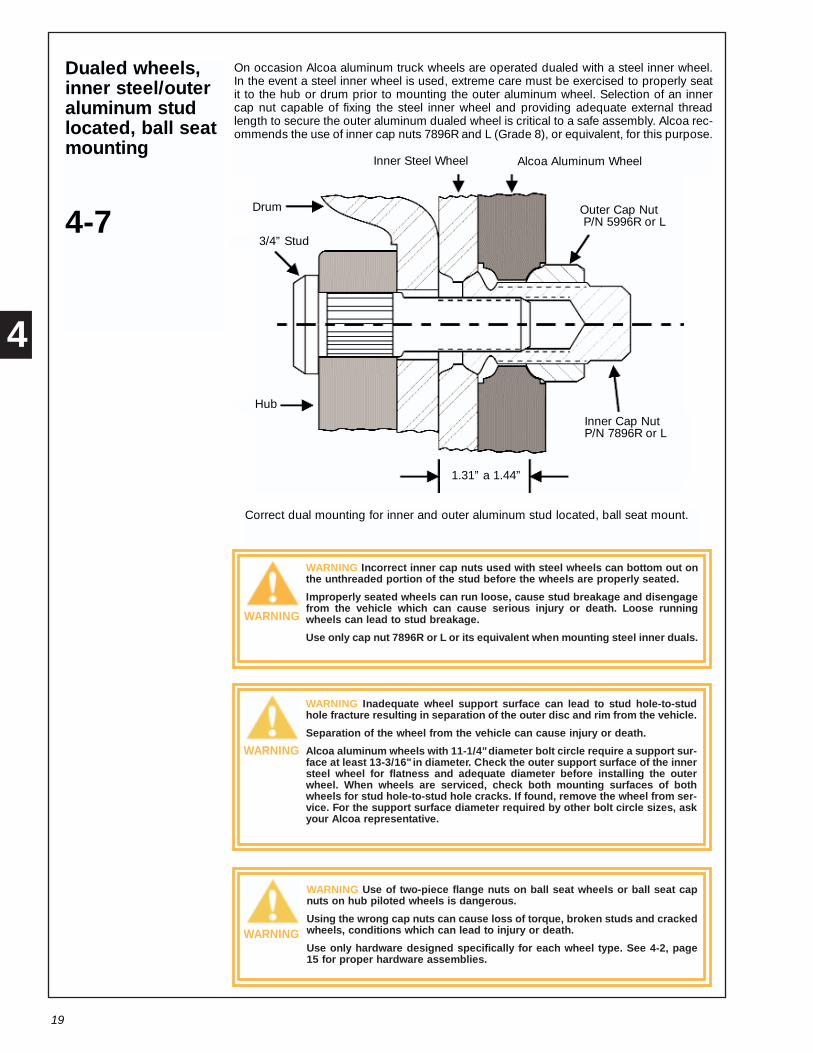
Dualed wheels,inner steel/outeraluminum studlocated, ball seatmounting
4-7
On occasion Alcoa aluminum truck wheels are operated dualed with a steel inner wheel.In the event a steel inner wheel is used, extreme care must be exercised to properly seatit to the hub or drum prior to mounting the outer aluminum wheel. Selection of an innercap nut capable of fixing the steel inner wheel and providing adequate external threadlength to secure the outer aluminum dualed wheel is critical to a safe assembly. Alcoa rec-ommends the use of inner cap nuts 7896R and L (Grade 8), or equivalent, for this purpose.
Inner Steel Wheel
Drum
3/4” Stud
Hub
1.31” a 1.44”
Correct dual mounting for inner and outer aluminum stud located, ball seat mount.
Outer Cap NutP/N 5996R or L
Inner Cap NutP/N 7896R or L
Alcoa Aluminum Wheel
WARNING Incorrect inner cap nuts used with steel wheels can bottom out onthe unthreaded portion of the stud before the wheels are properly seated.
Improperly seated wheels can run loose, cause stud breakage and disengagefrom the vehicle which can cause serious injury or death. Loose runningwheels can lead to stud breakage.
Use only cap nut 7896R or L or its equivalent when mounting steel inner duals.
WARNING Inadequate wheel support surface can lead to stud hole-to-studhole fracture resulting in separation of the outer disc and rim from the vehicle.
Separation of the wheel from the vehicle can cause injury or death.
Alcoa aluminum wheels with 11-1/4" diameter bolt circle require a support sur-face at least 13-3/16" in diameter. Check the outer support surface of the innersteel wheel for flatness and adequate diameter before installing the outerwheel. When wheels are serviced, check both mounting surfaces of bothwheels for stud hole-to-stud hole cracks. If found, remove the wheel from ser-vice. For the support surface diameter required by other bolt circle sizes, askyour Alcoa representative.
WARNING Use of two-piece flange nuts on ball seat wheels or ball seat capnuts on hub piloted wheels is dangerous.
Using the wrong cap nuts can cause loss of torque, broken studs and crackedwheels, conditions which can lead to injury or death.
Use only hardware designed specifically for each wheel type. See 4-2, page15 for proper hardware assemblies.
WARNING
WARNING
WARNING
4

ADVERTENCIA
20
Cap nut threadengagement,stud locatedwheels, ball seatmounting
4-8
The actual length of thread engagement present in an assembled wheel can not alwaysbe determined by visual inspection or measurement of a tightened assembly. The rela-tionship of the wheel cap nut seat to the end of the stud may vary. If there is any doubt thatenough thread engagement is present, the number of engaged threads may be counted.Tighten all nuts in the regular manner, then loosen one to hand-tightness. The number ofturns to disengage a 1- 1/8-inch nut should be at least five full turns. At least seven fullturns should be required to disengage a 3/4-inch nut. Ideally, when torqued to the properload, the stud should be flush with the face of the nut. The face of the nut may be recessedin nuts that are taller for improved wrenching. With most of the nuts in present use, a fewunengaged threads at the outer end will cause no problem provided at least 5-7 full turnsare required to disengage the nut depending on thread size.
Cap nuts made to Alcoa specification usually give more than the necessary threadengagement on a given stud.
Tightening studlocated, ball seatcap nuts
4-9
The number of turns to disengage a 1-1/8-inch nut should be at least five full turns. At leastseven full turns should be required to disengage a 3/4-inch nut.
WARNING Lubricants should not be applied to the cap nut seat or to the capnut-to-wheel contact surface.
Oiled seats can lead to over-torquing which can stretch studs causing failureof studs. Failed studs can cause the wheel to disengage from the vehicle,causing injury or death.
Lubricants must be completely removed from the cap nut seats and contactsurfaces if applied accidentally.
Cap nuts must be kept tight, and studs and nuts should be checked frequently. Nutsshould be retorqued if necessary. At tire changes, nuts and studs should be inspected forcracks and stripped or damaged threads. After each wheel mounting, cap nut torqueshould be checked with a torque wrench.
Impact wrenches, if used, should be carefully adjusted to apply torques within the limitsrecommended. Torquing of cap nuts should be done in recommended sequences.
WARNING Undertorqued cap nuts allow wheels to run loose, pounding out(deforming) the ball seats, fatiguing studs or losing nuts. Overtorquing canstretch studs causing them to fail.
Both under and overtorquing can lead to wheel disengagement, causing injuryor death.
Check all parts, including wheels, studs and cap nuts. Check mounting facesof wheels, hubs and drums. Check for dirt, corrosion or damage. Remove dirtand rust; replace damaged parts. Follow correct tightening sequences andtorque levels.
Continued on next page
WARNING
4

21
Tightening studlocated, ball seatcap nuts (continued)
Stud located, ball seat mounting system.
It is recommended that stud threads on stud located mounting systems be lubricated withSAE 30W oil and torqued between 350 and 400 foot-pounds. If threads are not lubricated,torque to between 450 and 500 foot-pounds. Note: when dualing steel wheels with Alcoaaluminum wheels, follow the steel wheel manufacturer’s recommendations regarding theproper torque and use of thread lubricants to mount the wheel.
WARNING Application of lubricant to the ball seats can cause excessivetorque. Over torque can stretch studs causing them to fail.
Overtorquing can lead to wheel disengagement causing injury or death.
Do not allow oil to contact ball seats or mounting surfaces of the wheel, hubor drum. Do not use aerosol cans for lubrication of stud threads.
On vehicles equipped to accept wheels manufactured for use with the stud located ballseat mounting system, wheel studs on the right side of the vehicle have right-hand threadsand those on the left have left-hand threads. The "R" and "L" on the studs and nuts indicateright and left-hand threads respectively (see 4-2, page 15).
After mounting a wheel over the studs, snug up the cap nuts in the order shown in the illus-trations that follow. After all the cap nuts have been snugged, tighten the cap nuts to therecommended torques, following the same tightening sequence.
Five Stud Six Stud
Ten StudEight StudContinued on the next page
WARNING
4
OIL

22
Tightening studlocated, ball seatcap nuts(continued)
After 50-100 miles of operation, torque should be rechecked. Loosen outer cap nuts onevery other stud to check the torque on inner cap nuts, then retorque outer cap nuts.Repeat steps on remaining studs. Check torque frequently from then on. If nuts requirefrequent tightening, studs break frequently, or wheel nut seats are pounding out, hardwareand mounting practices should be reviewed. Note: whenever the outer cap nut is loosenedALWAYS retorque the inner cap nut before retorquing the outer cap nut.
Single, dualedand wide basewheels, hubpiloted mounting,two-pieceflange nuts
4-10
Most U.S. manufacturers of highway trucks, tractors and trailers which incorporate the hubpiloted wheel mounting system require wheel studs and cap nuts which utilize metricthreads. Most frequently these are of a size designated as M22x1.5.
Generally the same diameter stud is used to mount either single or dualed wheels.
Studs on both sides of the vehicle are right-hand threads thereby eliminating the need forcap nuts peculiar to either the right or left side of the vehicle. The same cap nut is used tomount dualed or single wheels. Proper stud standout for single wheels is 2-inch (50.8mm)minimum, dualed wheels require 2.81-inch (71.4mm) minimum and single wide basewheels require 2.32-inch (59mm).
Note: Some stud located ball seat wheels have the same number of holes and bolt circlediameter as hub piloted wheels. They should not be mixed.
Typical assembly of single and dual wheels of hub piloted type with 33mm hex head two-piece flange nut, Part No. 39701. If hex nuts with higher overall height are used, more studlength is required, Part No. 39691.
Continued on the next page.
4

WARNING
23
Single, dualedand wide basewheels, hubpiloted mounting,two-pieceflange nuts (continued)
Hubs designed for steel hub piloted wheels may not have enough pilot length to locatedualed aluminum wheels. Pay close attention to pilot length, particularly when convertingfrom steel to aluminum duals. Measure the hub pilot to make sure the hub has a minimumpilot length of 1.06-inch or 27mm for dualed wheels.
Typically, hub piloted Alcoa aluminum wheels are mounted using two-piece flange nut(Part No. 39701) with a 33mm hex head and a nut height of 1.06-inches (27mm). If nutswith higher over all height are used more stud length is required.
When mounting painted steel inner dual wheels with outer aluminum wheels, be cautiousof excessive paint build-up on the inner steel wheel. Excessive paint can reduce the clamp-ing force and allow the wheels to become loose.
Match mounted dual wheels should be put on the vehicle with the valve stems 180° apart.
Tighteninghub pilotedmounting,two-pieceflange nuts
4-11
Flange nuts must be kept tight, and studs and nuts should be checked frequently. At tirechanges, nuts and studs should be inspected to be sure they are in good condition. If nutsrequire frequent tightening or studs break frequently, hardware and mounting practicesshould be reviewed.
Impact wrenches, if used, should be carefully adjusted to apply torques within the limitsrecommended. Torquing of flange nuts should be done in recommended sequences.
WARNING Undertorqued flange nuts allow wheels to run loose and fatiguestuds or lose nuts. Overtorquing can stretch studs causing them to fail.
Both under and overtorquing can lead to wheel disengagement causing injuryor death.
Check all parts including wheels, studs and flange nuts. Check mounting facesof wheels, hubs and drums. Check for dirt, corrosion or damage. Remove dirtand rust; replace damaged parts. Follow correct tightening sequences andtorque levels.
Two-piece flange nuts with a 33mm hex head design (see 4-2, page 15), used with hubpiloted wheels should be tightened to a torque of 450 to 500 foot-pounds. Two-pieceflange nuts with 1-1/2-inch hex head design and other designs have different torquerequirements. Inquire of the manufacturer for the proper torque values.
Wheel studs on both the right and left side hubs of vehicles utilizing the hub piloted wheelsystem have right-hand threads.
Prior to mounting hub piloted wheels, generously coat the wheel pilot or hub pads with anon-water-based lubricant to minimize corrosion product build-up between the wheel andhub pilot. Excessive corrosion build-up between the wheel and hub pilots can make wheelremoval difficult. Do not lubricate the face of the wheel, hub or brake drum (see illustrationon the next page).
Continued on the next page.
4
24
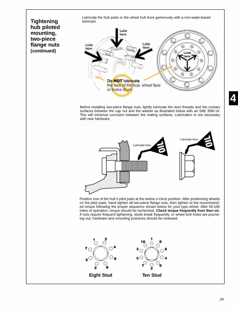
Tighteninghub pilotedmounting,two-pieceflange nuts(continued)
Lubricate the hub pads or the wheel hub bore generously with a non-water-basedlubricant.
Eight Stud Ten Stud
Before installing two-piece flange nuts, lightly lubricate the stud threads and the contactsurfaces between the cap nut and the washer as illustrated below with an SAE 30W oil.This will minimize corrosion between the mating surfaces. Lubrication is not necessarywith new hardware.
Position one of the hub’s pilot pads at the twelve o’clock position. After positioning wheelson the pilot pads, hand tighten all two-piece flange nuts, then tighten to the recommend-ed torque following the proper sequence shown below for your type wheel. After 50-100miles of operation, torque should be rechecked. Check torque frequently from then on.If nuts require frequent tightening, studs break frequently, or wheel bolt holes are pound-ing out, hardware and mounting practices should be reviewed.
4

25
Incorrectassemblies
4-12
WARNING Use of two-piece flange nuts on ball seat wheels, ball seat cap nutson hub piloted wheels or single-piece flange nuts in place of 2-piece flangenuts is dangerous.
Using the wrong wheel nuts can cause loss of torque, broken studs andcracked wheels, conditions which can lead to injury or death.
Use only hardware designed specifically for each wheel type. See 4-2, page15 for proper hardware assemblies.
The following are examples of incorrect wheel assemblies.
Incorrect use of two-piece flange nut.
Incorrect use of ball seat cap nut.
Incorrect use of one-piece flange nut positioned on Alcoa ball seat wheel.
Little (if any) contact area.
No positional location
WARNING
4

26
5 Care and Maintenance
Avoid abuse
5-1
Abuse can shorten the life of a wheel. Lack of care in changing a tire, heavy pounding ofthe wheel rim, overloading or hitting curbs at high speed or a sharp angle can damagewheels.
Wheel cap nuts must be kept tight (see 4-9, page 20). When checking the cap nuts ondual disc wheels utilizing the stud located ball seat mounting system, loosen every otherouter cap nut and then check the torque of the inner cap nuts. Retorque the loosenedouter cap nuts. Check all cap nuts for proper torque after the first use or any removal.Inspect wheels and check wheel nuts during service stops. (See Section 2, page 3). Dirtstreaks from cap nuts may indicate looseness.
Flange nuts must be kept tight, and studs and nuts should be checked frequently. At tirechanges nuts and studs should be inspected to be sure they are in good condition. Ifnuts require frequent tightening or studs break frequently, hardware and mounting prac-tices should be reviewed.
The proper torque for ball seat cap nuts is between 350 and 400 foot-pounds for studthreads lubricated with SAE 30W oil and between 450 and 500 foot-pounds if threads arenot lubricated. The proper torque for M22-1.5 two-piece flange nuts (33 mm hex head)is between 450 and 500 foot-pounds.
Keep wheel nutstight
5-2
Lead balanceweights (clip on)
5-3
Lead balance weights for Alcoa wheels are available from your Alcoa Wheel Distributor.With radial tires it may be necessary to reduce the tire pressure to allow clearance of theweight clamp over the rim flange.
Do not straightenwheels
5-4
Do not heat wheels in an attempt to soften them for straightening to repair damage fromstriking curbs or other causes. The special alloy used in these wheels is heat treated, anduncontrolled heating will weaken the wheel.
Do not rework, weld, heat or braze Alcoa aluminum wheels for any reason. This does notinclude normal wheel maintenance as described and approved by Alcoa.
5

27
Owner/in-serviceidentification
5-5
Some fleets wish to specially identify wheels as to OWNERSHIP and IN-SERVICE dates.Alcoa recommends that fleets and owner-operators adopt the practice of permanentlystamping wheels with the date they are first placed into service.
1. Use "Lo-Stress" stamps or equivalent.
2. Location of stamped areas on outside disc should be in space outward from a linebetween hand hole centers and a minimum of one inch from the periphery of any handhole.
3. Location of stamped identification on inside of wheel should be as close to the factoryidentification stamping as possible.
Valves
5-6
Alcoa drop center wheels for tubeless tires come from the factory with air valves installed.If it becomes necessary to replace an air valve, install it using the following torque values.
10-14 foot-pounds 7-11 foot-poundsfor Part Nos. for Part Nos.
TR 509 TR 542 Series
TR 510 TR 543 Series
TR 511 TR 544 Series
TR 545 Series
Replacement valves may be obtained from your authorized Alcoa Wheel Distributor.Always use silicone o-rings û not rubber û when reinstalling valve stems. Metal valve stemcaps are recommended over plastic.
Maintenanceagainst corrosion
5-7
1. Clean frequently with high pressure water from a hose. The use of a mild detergent willspeed the cleaning process. Use no harsh alkaline cleaners.
2. When tires are removed the entire wheel must be cleaned and inspected. (See Section2, page 3). With a wire brush, remove any foreign products from the tire side of the rim. Donot use a wire brush to remove dirt and corrosion products from the appearance surfaceof the wheel. Generously coat the entire air chamber surface with an approved surface pro-tectant and lubricant each time the tire is removed (See 3-1, page 11).
3. To maintain the original appearance of your Alcoa wheels, the following procedures arerecommended:
a. After installing new wheels and prior to operating your vehicle, use a sponge, cloth orsoft fiber brush to wash exposed wheel surfaces with a mild detergent and warm watersolution.
b. Rinse thoroughly with clean water.
c. Wipe dry to avoid water spots.
d. Wax the cleaned surface with Alcoa Advanced Aluminum Care System Polish orSimonize, Mothers, California Gold paste wax, No. 7 Car Wax or equivalent.
e. Clean your Alcoa truck wheels as frequently as required to maintain their appearance.
5
28
Identification
5-8
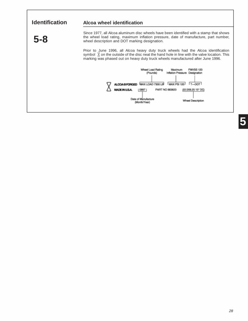
Alcoa wheel identification
Since 1977, all Alcoa aluminum disc wheels have been identified with a stamp that showsthe wheel load rating, maximum inflation pressure, date of manufacture, part number,wheel description and DOT marking designation.
Prior to June 1996, all Alcoa heavy duty truck wheels had the Alcoa identificationsymbol on the outside of the disc neat the hand hole in line with the valve location. Thismarking was phased out on heavy duty truck wheels manufactured after June 1996.
5
WARNING
29
Flat Base Wheel 6 for Tube-type TiresTube-typewheel partinterchangeability
6-1
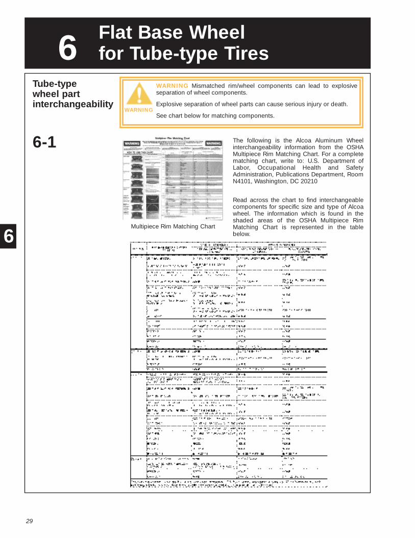
WARNING Mismatched rim/wheel components can lead to explosiveseparation of wheel components.
Explosive separation of wheel parts can cause serious injury or death.
See chart below for matching components.
Multipiece Rim Matching Chart
The following is the Alcoa Aluminum Wheelinterchangeability information from the OSHAMultipiece Rim Matching Chart. For a completematching chart, write to: U.S. Department ofLabor, Occupational Health and SafetyAdministration, Publications Department, RoomN4101, Washington, DC 20210
Read across the chart to find interchangeablecomponents for specific size and type of Alcoawheel. The information which is found in theshaded areas of the OSHA Multipiece RimMatching Chart is represented in the tablebelow.6
30
Mountingrecommendationsfor tubed tires
6-2
1. Inspect the wheel for damage. Do not use a bent, cracked, damaged or severely cor-roded wheel. (See Section 2, page 3).
2. Inspect ring(s) for corrosion, bending or other damage and discard if any is apparent.
3. Thoroughly clean the wheel and rings. Clean the wheel face with a mild detergent.Clean the tire bead seat areas and gutter flange with a wire brush.
4. Do not gouge or nick the wheel. Place wheels on a wooden floor or rubber mat. Alwaysuse a rubber, leather-faced or plastic mallet.
5. Inspect and clean the tire, tube, and flap before mounting ù replace if damaged, badlyworn or defective.
6. Insert lubricated tube and flap in tire.
7. Lubricate the tire beads and rim, then mount tire, tube and flap assembly onto rim. Donot use any lubricant which contains water or a solvent which can injure rubber.
8. Select the proper rim components and assemble to rim (see 6-3, page 31). Discardbent, damaged or corroded side and lock rings. Do not use any side or lock ring whichis not clearly identifiable.
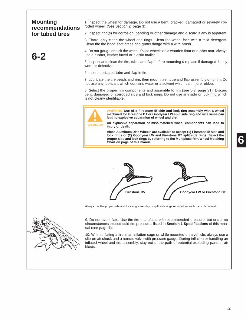
WARNING Use of a Firestone 5! side and lock ring assembly with a wheelmachined for Firestone DT or Goodyear LW split side ring and vice versa canlead to explosive separation of wheel and tire.
An explosive separation of miss-matched wheel components can lead toinjury or death.
Alcoa Aluminum Disc Wheels are available to accept (1) Firestone 5! side andlock rings or (2) Goodyear LW and Firestone DT split side rings. Select theproper side and lock rings by referring to the Multipiece Rim/Wheel MatchingChart on page of this manual.
Always use the proper side and lock ring assembly or split side rings required for each particular wheel.
9. Do not overinflate. Use the tire manufacturer's recommended pressure, but under nocircumstances exceed cold tire pressures listed in Section 1 Specifications of this man-ual (see page 1).
10. When inflating a tire in an inflation cage or while mounted on a vehicle, always use aclip-on air chuck and a remote valve with pressure gauge. During inflation or handling aninflated wheel and tire assembly, stay out of the path of potential exploding parts or airblasts.
WARNING
Firestone R5 Goodyear LW or Firestone DT
6

Alcoa Flat Base Wheels for Tube-type Tires That Use Goodyear LW or Firestone DT Split Side Rings Only(2 Piece Assemblies)
Wheel Size Alcoa Part Number Side Ring Identification StampingIdentification Stamping
22x8.00 LW 481010 R8022LW recommended or:R22X7.5-8.0-9.0LB-LW22X7.5-8.0DT-LB-LW (3)
22x7.50 LW 471010 R8022LW recommended or:R22X7.5-8.0-9.0LB-LW22X7.5-8.0DT-LB-LW (3)
31
Mounting oftubed tires
6-3
When mounting Alcoa flat base wheels for tube-type tires you must use the proper sidering or side and lock ring required for each wheel. The table below lists the Alcoa tube-type wheels currently in production and the proper side ring or side and lock ring identifi-cation recommended for each wheel. See the Multipiece Rim Matching Chart on page 1for information on older wheels with part numbers not shown here.
Lubricate tube, flap and wheel. Insert tube and flap intotire. Place them on the wheel so that the valve is alignedwith the valve slot.
Place side ring on wheel and tire and stand on the ringto position it below the lock ring groove. If a split sidering is required, start the leading edge and walk the sidering onto the wheel
Seat the second end of the split side ring or lock ringwith a rubber, plastic or leather-facet mallet as shown.Check carefully to see that the split side ring or side ringand lock ring assembly is in the proper position. If not,completely remove the components and start over.
Inflate to 10 psi. Check to see that all components areproperly in place. If not, deflate the tire by removing thevalve core and reposition components properly. Placeina a safety cage or other suitable restraining device(refer to OSHA rule 1910.177, paragraph B, see Section7, page 33). Use clip-on chuck and stand behind barri-er during inflation. Do not lean on cage. Inflate to rec-ommended pressure. Deflate completely to avoid local-ized over-stretching of the tube. Reinflate to the tiremanufacturer’s recommended pressure.
If the wheel requires a lock ring, start the leading edgeof the lock ring being sure that it is seating in themachined groove. Then walk the lock ring onto thewheel, as illustrated
1
3
2
4
6
Current Alcoa part numbers (i.e., 481010) end in 0-1-2 or 3, indicating a finish conditionwhich does not affect the compatibility of parts as shown in the table.

WARNING
32
Demountingrecommendationsfor tubed tires
6-4
WARNING An inflated tire contains air under pressure which can be adangerous explosive force.
Explosive separation of a tire and wheel can cause serious injury or death.
Follow proper service procedures to avoid injury or death.
1. Before removing wheel from vehicle, remove the valve core from the valve stem toensure complete deflation of tire.
2. Do not gouge or nick the wheel. Place aluminum wheels on a clean wooden floor orrubber mat.
3. Always use a rubber, leather-faced or plastic mallet.
4. Keep tire tools smooth. Use them with care. Rim gouges or nicks near the fixedflange can cause cracks.
5. Remove steel side rings carefully. If bead is well-loosened, rings can be removedwithout gouging the wheel.
6. Discard bent, damaged or corroded side and lock rings. Using bent, damaged orcorroded rings can shorten service life of wheel and introduce the danger of anexplosive separation.
Demounting oftubed tires
6-5NOTICE: Tire must be com-pletely deflated and valvecore removed beforedemounting
If manually breaking the tire beads from the wheel,it is important to use the proper tools. Tire toolsmay be inserted next to the tire side wall and theside ring or locking ring. Tools must be smooth andused with care if gouging the rim is to be avoided.A stop, welded to the tool, is recommended
Insert the tapered end of the tire tool into the notchon the locking ring. Pry up carefully to avoid bend-ing the ring and gouging the wheel.
Using the same procedures as outlined in Step 1,loosen the bead on the opposite side of the wheel.Do not drive tools into rim area. Lift wheel from tire.
Once the tool is inserted, pry down and out as illus-trated. Leaving one tool in position, work the otheraround the tire until the bead is completely free.
1
3
2
4
6
33
7 OSHA Regulations
OSHARegulations
7-1
Federal Register Vol. 49. No. 24 Friday, February 3, 1984 Rules and Regulations
Signed at Washington, D.C., this 30th day of January 1984. Thorne G. Auchter, Assistant Secretary of Labor.
Part 1910-(AMENDED) Section 1910.177 is amended by revising the title to read, "SER-VICING MULTI-PIECE AND SINGLE PIECE RIM WHEELS," by revising paragraphs (a), (b),(c)(1), (c)(1)(i), (c)(1)(ii), (c)(2), (c)(2)(ii), (c)(2)(iii), (c)(2)(iv), (c)(2)(v), (c)(2)(vii), (c)(3),(d)(2), (d)(3), (d)(4), (d)(5), (e), introductory text of (f), (f)(2), (f)(3), and (f)(4), and by addingnew paragraphs (c)(2)(iii), (d)(6), (f)(11) and (g). As amended, *1910.177 reads as follows:*1910.177 Servicing multi-piece and single piece rim wheels.
(a) Scope(1) This section applies to the servicing of multi-piece and single piece rim wheels used on
large vehicles such as trucks, tractors, trailers, buses and off-road machines. It doesnot apply to the servicing of rim wheels used on automobiles, or on pickup trucks andvans utilizing automobile tires or truck tires designated "LT."
(2) This section does not apply to employers and places of employment regulated underthe Construction Safety Standards, 29 CFR Part 1926: the Agriculture Standards, 29CFR Part 1928; or the Maritime Standards, 29 CFR 1915-1918.
(3) All provisions of this section apply to the servicing of both single piece rim wheels andmulti-piece rim wheels unless designated otherwise.
(b) Definitions"Barrier" means a fence, wall or other structure or object placed between a single piece rimwheel and an employee during tire inflation, to contain the rim wheel components in theevent of the sudden release of the contained air of the single piece rim wheel.
"Charts" means the United States Department of Transportation, National Highway TrafficSafety Administration (NHTSA) publications entitled "Safety Precautions for Mounting andDemounting Tube-Type Truck/Bus Tires" and "Multi-Piece Rim Wheel Matching Chart", orany other publications such as rim manuals containing, at a minimum, the same instruc-tions, safety precautions and other information contained on those charts that are applic-able to the types of rim wheels being serviced.
"Installing a rim wheel" means the transfer and attachment of an assembled rim wheel ontoa vehicle axle hub. "Removing" means the opposite of installing.
"Mounting a tire" means the assembly or putting together of the wheel and tire compo-nents to form a rim wheel, including inflation. "Demounting" means the opposite ofmounting.
7
34
OSHARegulations(continued)
"Multi-piece rim wheel" means the assemblage of a multi-piece wheel with the tire tubeand other components.
"Multi-piece wheel" means a vehicle wheel consisting of two or more parts, one of whichis a side or locking ring designed to hold the tire on the wheel by interlocking componentswhen the tire is inflated.
"Restraining device" means an apparatus such as a cage, rack, assemblage of bars andother components that will constrain all rim wheel components during an explosiveseparation of a multi-piece rim wheel, or during the sudden release of the contained air ofa single piece rim wheel.
"Rim manual" means a publication containing instructions from the manufacturer or otherqualified organization for correct mounting, demounting, maintenance, and safetyprecautions peculiar to the type of wheel being serviced.
"Rim wheel" means an assemblage of tire, tube and liner (where appropriate), and wheelcomponents.
"Service" or "servicing" means the mounting and demounting of rim wheels, and relatedactivities such as inflating, deflating, installing, removing, and handling.
"Service area" means that part of an employer's premises used for the servicing of rimwheels, or any other place where an employee services rim wheels.
"Single piece rim wheel" means the assemblage of single piece rim wheel with the tire andother components.
"Single piece wheel" means a vehicle wheel consisting of one part, designed to hold thetire on the wheel when the tire is inflated.
"Trajectory" means any potential path or route that a rim wheel component may travelduring an explosive separation, or the sudden release of the pressurized air, or an area atwhich an airblast from a single piece rim wheel may be released. The trajectory maydeviate from paths which are perpendicular to the assembled position or the rim wheel atthe time of separation or explosion.
"Wheel" means that portion of a rim wheel which provides the method of attachment of theassembly to the axle of a vehicle and also provides the means to contain the inflatedportion of the assembly (i.e., the tire and/or tube)
(c) Employee training
(1) The employer shall provide a program to train all employees who service rim wheelsin the hazards involved in servicing those rim wheels and the safety procedures to be fol-lowed.
(i) The employer shall assure that no employee services any rim wheel unless the employ-ee has been trained and instructed in correct procedures of servicing the type of wheelbeing serviced, and in the safe operating procedures described in paragraphs (f) and (g)of this section.
(ii) Information to be used in the training program shall include, at a minimum, the applic-able data contained in the charts (rim manuals) and the contents of this standard.
(iii) Where an employer knows or has reason to believe that any of his employees isunable to read and understand the charts or rim manual, the employer shall assure thatthe employee is instructed concerning the contents of the charts and rim manual in a man-ner which the employee is able to understand.
(2) The employer shall assure that each employee demonstrates and maintains the abili-ty to service rim-wheels safely, including performance of the following tasks:
7

35
OSHARegulations(continued)
(i) Demounting of tires (including deflation);
(ii) Inspection and identification of the rim wheel components:
(iii) Mounting of tires (including inflation with a restraining device or other safeguardrequired by this section);
(iv) Use of the restraining device or barrier, and other equipment required by this section;
(v) Handling of rim wheels;
(vi) Inflation of the tire when a single piece rim wheel is mounted on a vehicle;
(vii) An understanding of the necessity of standing outside the trajectory both duringinflation of the tire and during inspection of the rim wheel following inflation; and
(viii) Installation and removal of rim wheels.
(3) The employer shall evaluate each employee's ability to perform these tasks and toservice rim wheels safely, and shall provide additional training as necessary to assure thateach employee maintains his or her proficiency.
(d) Tire servicing equipment.
(1) The employer shall furnish a restraining device for inflating tires on multi-piecewheels.
(2) The employer shall provide a restraining device or barrier for inflating tires on singlepiece wheels unless the rim wheel will be bolted onto a vehicle during inflation.
(3) Restraining devices and barriers shall comply with the following requirements:
(i) Each restraining device or barrier shall have the capacity to withstand themaximum force that would be transferred to it during a rim wheel separationoccurring at 150 percent of the maximum tire specification pressure for the type ofrim wheel being serviced.
(ii) Restraining devices and barriers shall be capable of preventing the rim wheelcomponents from being thrown outside or beyond the device or barrier for any rimwheel positioned within or behind the device:
(iii) Restraining devices and barriers shall be visually inspected prior to each day'suse and after any separation of the rim wheel components or sudden release ofcontained air. Any restraining device or barrier exhibiting damage such as the following defects shall be immediately removed from service:
(A) Cracks at welds;
(B) Cracked or broken components;
(C) Bent or sprung components caused by mishandling, abuse, tire explosion or rim wheel separation;
(D) Pitting of components due to corrosion; or
(E) Other structural damage which would decrease its effectiveness.
(iv) Restraining devices or barriers removed from service shall not be returned to serviceuntil they are repaired and reinspected. Restraining devices or barriers requiringstructural repair such as component replacement or rewelding shall not be returned toservice until they are certified by either the manufacturer of a Registered ProfessionalEngineer as meeting the strength requirements of paragraph (d)(3)(i) of this section.
7

36
OSHARegulations(continued)
(4) The employer shall furnish and assure that an air line assembly consisting of thefollowing components be used for inflating tires:
(i) A clip-on chuck;
(ii) An in-line valve with a pressure gauge or a presettable regulator; and
(iii) A sufficient length of hose between the clip-on chuck and the in-line valve(if one is used) to allow the employee to stand outside the trajectory.
(5) Current charts (rim manuals) containing instructions for the types of wheels beingserviced shall be available in the service area.
(6) The employer shall furnish and assure that only tools recommended in the rimmanual for the type of wheel being serviced are used to service rim wheels.
(e) Wheel component acceptability.
(1) Multi-piece wheel components shall not be interchanged except as provided in thecharts or in the applicable rim manual.
(2) Multi-piece wheel components and single piece wheels shall be inspected prior toassembly. Any wheel or wheel component which is bent out of shape, pitted fromcorrosion, broken, or cracked shall not be used and shall be marked or taggedunserviceable and removed from the service area. Damaged or leaky valves shall bereplaced.
(3) Rim flanges, rim gutters, rings, bead seating surfaces and the bead areas of tires shallbe free of any dirt, surface rust, scale or loose or flaked rubber built-up prior to mountingand inflation.
(4) The size (bead diameter and tire/wheel widths) and type of both the tire and the wheelshall be checked for compatibility prior to assembly of the rim wheel.
(f) Safe operating procedure - multi-piece rim wheels.
The employer shall establish a safe operating procedure for servicing multi-piece rimwheels and shall assure that employees are instructed in and follow that procedure. Theprocedure shall include at least the following elements:
(1) Tires shall be completely deflated before demounting by removal of the valve core.
(2) Tires shall be completely deflated by removing the valve core before a rim wheel isremoved from the axle in either of the following situations:
(i) When the tire has been driven underinflated at 80% or less of its recommended pressure, or
(ii) When there is obvious or suspected damage to the tire or wheel components.
(3) Rubber lubricant shall be applied to bead and rim mating surfaces during assembly ofthe wheel and inflation of the tire, unless the tire or wheel manufacturer recommendsagainst it.
7

37
OSHARegulations(continued)
(4) If a tire on a vehicle is underinflated but has more than 80% of the recommendedpressure, the tire may be inflated while the rim wheel is on the vehicle provided remotecontrol inflation equipment is used, and no employees remain in the trajectory duringinflation.
(5) Tires shall be inflated outside a restraining device only to a pressure sufficient to forcethe tire bead onto the rim ledge and create an airtight seal with the tire and bead.
(6) Whenever a rim wheel is in a restraining device the employee shall not rest or lean anypart of his body or equipment on or against the restraining device.
(7) After tire inflation, the tire and wheel components shall be inspected while still withinthe restraining device to make sure that they are properly seated and locked. If furtheradjustment to the tire or wheel components is necessary, the tire shall be deflated byremoval of the valve core before the adjustment is made.
(8) No attempt shall be made to correct the seating of side and lock rings by hammering,striking or forcing the components while the tire is pressurized.
(9) Cracked, broken, bent or otherwise damaged rim components shall not be reworked,welded, brazed, or otherwise heated.
(10) Whenever multi-piece rim wheels are being handled, employees shall stay out of thetrajectory unless the employer can demonstrate that performance of the servicing makesthe employee's presence in the trajectory necessary.
(11) No heat shall be applied to a multi-piece wheel or wheel component.
(g) Safe operating procedure - single piece rim wheels.
The employer shall establish a safe operating procedure for servicing single piece rimwheels and shall assure that employees are instructed in and follow that procedure. Theprocedure shall include at least the following elements:
(1) Tires shall be completely deflated by removal of the valve core before demounting.
(2) Mounting and demounting of the tire shall be done only from the narrow ledge side ofthe wheel. Care shall be taken to avoid damaging the tire beads while mounting tires onwheels. Tires shall be mounted on compatible wheels of matching bead diameter andwidth.
(3) Nonflammable rubber lubricant shall be applied to bead and wheel mating surfacesbefore assembly of the rim wheel, unless the tire or wheel manufacturer recommendsagainst the use of any rubber lubricant.
(4) If a tire changing machine is used, the tire shall be inflated only to the minimumpressure necessary to force the tire bead onto the rim ledge while on the tire changingmachine.
(5) If a bead expander is used, it shall be removed before the valve core is installed andas soon as the rim wheel becomes airtight (the tire bead slips onto the bead seat).
(6) Tires may be inflated only when contained within a restraining device, positionedbehind a barrier or bolted on the vehicle with the lug nuts fully tightened.
(7) Tires shall not be inflated when any flat, solid surface is in the trajectory and within onefoot of the sidewall.
(8) Employees shall stay out of the trajectory when inflating a tire.
(9) Tires shall not be inflated to more than the inflation pressure stamped in the sidewallunless a higher pressure is recommended by the manufacturer.
(10) Tires shall not be inflated above the maximum pressure recommended by themanufacturer to seat the tire bead firmly against the rim flange.
(11) No heat shall be applied to a single piece wheel.
(12) Cracked, broken, bent, or otherwise damaged wheels shall not be reworked, welded,brazed, or otherwise heated.
7
38
OSHARegulations(continued)
Appendix B - Ordering Information for NHTSA Charts
OSHA has reprinted the NHTSA Charts as part of a continuing campaign to alert rim wheelservicing personnel of the industry accepted procedures for servicing multi-piece rimwheels.
Reprints of the charts are available through Occupational Safety and Health Administration(OSHA) Area Offices. The address and telephone number of the nearest OSHA Area Officecan be obtained by looking in the local telephone directory under U. S. Government, U. S.Department of Labor, Occupational Safety and Health Administration.
Single copies are available without charge.
Individuals, establishments and other organizations desiring multiple copies of thesecharts may order them from the Publications Office, U. S. Department of Labor, RoomN4101, Washington, D.C. 20210.
Telephone: (202)523-9667.
(FR Doc. 84 - 2884 Filed 2-2-84:8:45 a.m.)BILLING CODE 4510-26-M
7

39
8 Glossary of Common Terms
Glossary ofCommon Terms
8-1
1/2 DUAL SPACING - One half the distance between the two center lines of dualedwheels. The dimension is the same as the OUTSET dimension.
2-PIECE FLANGE NUT - A two-piece washer and nut combination used to secure hubpiloted wheels.
AIR CHAMBER - The space enclosed by a tire and wheel rim or inner tube.
BEAD SEAT - The area along the outer edges of the rim where the mounted tire and rimare in contact.
BOLT CIRCLE - The circle defined by the centers of the bolt holes (stud holes) of a wheel,dimensions stated in diameter inches or millimeters.
BOLT HOLE - Hole found in the disc of the wheel through which the bolt (stud) passes.
BORE - See "HUB BORE."
CENTER BORE - See "HUB BORE."
CONE LOCK CAP NUT - See "2-PIECE FLANGE NUT."
DC - Abbreviation for drop center.
DISC AREA - The vertical wheel face which supports the rim.
DISC WHEEL - A one-piece (forged) or two-piece (welded) assembly of a disc and a rim.
DROP CENTER - The well or center portion of the wheel rim.
FLAT BASE WHEEL - A multi-piece wheel with a removable side ring.
FOOT-POUNDS - The measure of the amount of torque applied to a cap nut or other part.May be measured with a torque wrench.
GUTTER FLANGE - A groove which supports the removable portion of a multi-piecewheel.
HUB BORE - The center hole of a disc wheel, dimensions stated in diameter inches ormillimeters.
HUB PILOTED MOUNTING - A wheel mounting system which uses the hub to center thewheel and two-piece flange nuts to secure it.
in. - Abbreviation for inches.
INNER CAP NUT - Cap nut used to mount the inner wheel in a dualed stud located wheelsystem.
INSET - The distance from the wheel mounting surface to the rim centerline when thecenterline is placed inboard of the mounting surface.
kg - Abbreviation for kilogram (weight measurement), equal to 1000 grams.
kPa - Abbreviation for kilo Pascals (pressure measurement).
8

40
Glossary ofCommon Terms(continued)
LOCK RING - The third piece of a three rim assembly which positions and supports theside ring to the rim base.
MAXIMUM INFLATION - The highest amount of air pressure allowed, measured atnormal ambient temperatures.
mm - Abbreviation for millimeters.
MULTI-PIECE WHEEL - A wheel assembly in which the rim portion of the wheel consistsof two or more separate parts.
OFFSET - See "OUTSET."
OPEN SIDE - The side of the wheel opposite the disc face.
OSHA - Abbreviation for the U.S. Department of Labor, Occupational Health and SafetyAdministration.
OUTER CAP NUT - A cap nut used to secure the outer stud located wheel in a dualedwheel pair and thread onto the inner cap nut.
OUTSET - The distance from the mounting surface of the wheel to the rim centerline whenthe rim centerline is mounted outboard of the hub face. This dimension is the same as the1/2 DUAL SPACING dimension.
PILOT PAD - The raised surfaces on a hub used to center a hub piloted wheel.
PSI - Abbreviation for pounds per square inch.
REVERSIBLE - Term applied to a disc wheel which can be reversed on the hub withoutchanging the position of the tire centerline.
RIM CENTERLINE - A line to the radial axis of the wheel running through the mid pointbetween the rim flanges.
RIM FLANGE - That portion of the rim which extends above the rim surface which retainsthe tire bead.
RIM - That portion of the wheel which supports the tire.
SIDE RING - A removable piece of a multi-piece wheel assembly which provides lateralsupport for one tire bead.
SINGLE CAP NUT - A cap nut used to secure single wheels or outer dual wheels.
STUD - A threaded bolt extending from the hub surface to which the wheels are securedby the cap nuts.
STUD LOCATED, BALL SEAT MOUNTING - A wheel mounting system which uses thestuds and spherical ball seat cap nuts to center and secure the wheel.
TIRE BEAD - That surface of the tire which contacts the angled surface of the wheel rim.
TORQUE - The amount of force used to tighten cap nuts. Usually stated in foot-pounds orkilograms and measured with a torque wrench.
WHEEL MOUNTING FACE - That portion of the wheel face which contacts the hub orbrake drum.
wt. - Abbreviation for weight.
8

41
Wheelmeasurement
8-2
How to measure minimum dual spacing
Minimum dual spacing measurement is determined by the tire manufacturer and may beobtained from the tire manufacturer's handbook. To determine if the Alcoa aluminum dualwheel assembly has adequate minimum dual spacing for the selected tires, double thewheel outset measurement of the Alcoa wheel used. If the doubled outset measurementis equal to or greater than the tire manufacturer's recommendation, there will be sufficientminimum dual spacing. Wheel inset and outset is given for each Alcoa wheel on pages 2and 3. Both inset and outset wheels are measured from the mounting surface of the wheelto the center line of the rim. Maintaining proper tire inflation and load ratings are essentialto maintaining proper minimum dual spacing.
Dual Spacing
Tire Clearance
Vehicleclearance
Tire section width
WheelInset
Backspace
Tire center lineTire center line
Wheel outset(same as offsetor dual spacing)
Centerhole dia.
Boltcircle dia.
8

42
InchFraction,Decimal andMillimeterEquivalentsChart(Up to 1inch)
9-1
9 Conversion Tables
9

43
ConversionFormulas
9-2
Inches to Millimeters
Inches 25.4 = Millimeters
Millimeters to Inches
Millimeters 0.03937 = Inches
PSI to kPa
PSI 6.8948 = kPa
kPa to PSI
kPa 0.145 = PSI
Pounds to Kilograms
Pounds 0.4536 = kg
Kilograms to Pounds
kg 2.2050 = Pounds
Foot-pounds to Kilogram Meters
Ft-lbs 0.13826 = kgm
Kilogram Meters to Foot-pounds
kgm 7.23 = Ft-lbs
9

Alcoa Inc.Wheel Products International1600 Harvard AvenueCleveland, Ohio 44105(800) 242-9898
Alcoa Inter-America, Inc.115-A Matheson Blvd. West, Suite 207Mississauga, Ontario, Canada L5R 3L1(800) 668-1150
Copyright © 1997Alcoa Inc.All Rights Reserved
Form E37-13584Printed in USA 1/99/50M