Embed Size (px)
Citation preview
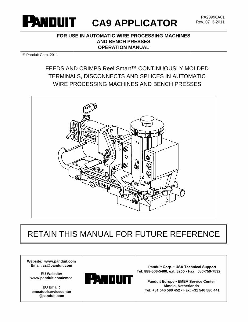
CA9 APPLICATOR PA23998A01
Rev. 07 3-2011
FOR USE IN AUTOMATIC WIRE PROCESSING MACHINES
AND BENCH PRESSES
OPERATION MANUAL
© Panduit Corp. 2011
FEEDS AND CRIMPS Reel Smart™ CONTINUOUSLY MOLDED
TERMINALS, DISCONNECTS AND SPLICES IN AUTOMATIC
WIRE PROCESSING MACHINES AND BENCH PRESSES
RETAIN THIS MANUAL FOR FUTURE REFERENCE
Website: www.panduit.com Email: [email protected]
EU Website:
www.panduit.com/emea
EU Email: emeatoolservicecenter
@panduit.com
Panduit Corp. • USA Technical Support
Tel: 888-506-5400, ext. 3255 • Fax: 630-759-7532
Panduit Europe • EMEA Service Center
Almelo, Netherlands
Tel: +31 546 580 452 • Fax: +31 546 580 441
CA9 APPLICATOR
TABLE OF CONTENTS
INTRODUCTION ................................................................................................................................. 1
SYSTEM SPECIFICATIONS .............................................................................................................. 1
SAFETY PRACTICES ........................................................................................................................ 1
WIRE PROCESSING MACHINE / PRESS COMPATIBILITY
BY MANUFACTURER ..................................................................................................................... 3
APPLICATOR INSTALLATION ......................................................................................................... 4
AMP CLS III G, CLS IV, & CLS IV PLUS WIRE PROCESSING MACHINES
& G BENCH PRESS ..................................................................................................... 4
AMP CLS II & CLS III WIRE PROCESSING MACHINES AND T BENCH PRESS ......... 5
ARTOS CS-600 WIRE PROCESSING MACHINE WITH AMP G PRESS ...................... 6
ARTOS CS-600 WIRE PROCESSING MACHINE WITH TU-10 PRESS ........................ 8
ARTOS MTX Series 5 WIRE PROCESSING MACHINE WITH TU-10 PRESS .............. 9
GAMMA MECCANICA T20P-110V BENCH PRESS ..................................................... 10
KODERA SERIES C451/C450 & C551/C550 WIRE PROCESSING MACHINES ........ 11
KOMAX GAMMA 311 WIRE PROCESSING MACHINE
WITH MECAL K300 PRESS ....................................................................................... 12
KOMAX GAMMA 333 OR ALPHA 433 WIRE PROCESSING MACHINE
WITH MCI 711 PRESS ............................................................................................... 13
KOMAX ALPHA 411 WIRE PROCESSING MACHINE
WITH MECAL PE7 OR P107 PRESS ......................................................................... 14
KOMAX 40T WIRE PROCESSING MACHINE WITH MECAL PE7 PRESS ................. 16
MEGOMAT ASM 3001A & PRIMO WIRE PROCESSING MACHINES ........................ 17
Panduit CP-862 BENCH PRESS ................................................................................... 18
Panduit CP-871 BENCH PRESS ................................................................................... 19
SCHLEUNIGER CRIMPCENTER 12 WIRE PROCESSING MACHINE
WITH ACP 01 PRESS ................................................................................................ 20
SHINMAYWA TRD111 OR TR111 WIRE PROCESSING MACHINE ........................... 21
APPLICATOR SETUP ...................................................................................................................... 22
DIE INSERT INSTALLATION ........................................................................................ 23
DIE INSERT CHANGEOVER ........................................................................................ 24
Reel Smart™ SYSTEM REFERENCE TABLE ................................................................................ 25
CRIMP SHUT HEIGHT TOLERANCE TEST ................................................................. 26
APPLICATOR LOADING ............................................................................................... 26
OPERATION ..................................................................................................................................... 28
SAFETY CHECKLIST .................................................................................................... 28
OPERATION PROCEDURE .......................................................................................... 28
MAINTENANCE ............................................................................................................. 28
TROUBLESHOOTING ...................................................................................................................... 28
DETERMINING CORRECT AND INCORRECT TERMINATIONS ............................... 28
TROUBLESHOOTING CHECKLIST ............................................................................. 29
CA9 APPLICATOR
CA9 APPLICATOR: PA23998A01_07 Page: 1 of 30 3-2011
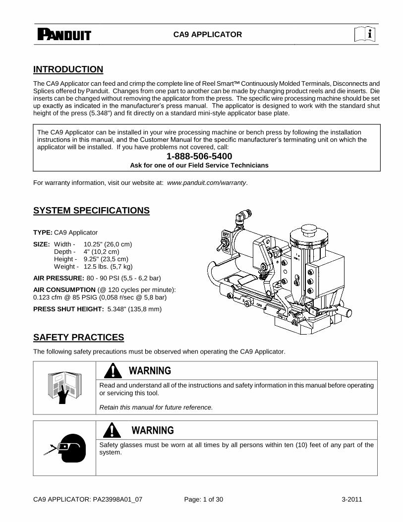
INTRODUCTION
The CA9 Applicator can feed and crimp the complete line of Reel Smart Continuously Molded Terminals, Disconnects and Splices offered by Panduit. Changes from one part to another can be made by changing product reels and die inserts. Die inserts can be changed without removing the applicator from the press. The specific wire processing machine should be set up exactly as indicated in the manufacturer’s press manual. The applicator is designed to work with the standard shut height of the press (5.348") and fit directly on a standard mini-style applicator base plate.
The CA9 Applicator can be installed in your wire processing machine or bench press by following the installation instructions in this manual, and the Customer Manual for the specific manufacturer’s terminating unit on which the applicator will be installed. If you have problems not covered, call:
1-888-506-5400 Ask for one of our Field Service Technicians
For warranty information, visit our website at: www.panduit.com/warranty.
SYSTEM SPECIFICATIONS
TYPE: CA9 Applicator
SIZE: Width - 10.25" (26,0 cm) Depth - 4" (10,2 cm) Height - 9.25" (23,5 cm) Weight - 12.5 lbs. (5,7 kg)
AIR PRESSURE: 80 - 90 PSI (5,5 - 6,2 bar)
AIR CONSUMPTION (@ 120 cycles per minute): 0.123 cfm @ 85 PSIG (0,058 /sec @ 5,8 bar)
PRESS SHUT HEIGHT: 5.348" (135,8 mm)
SAFETY PRACTICES
The following safety precautions must be observed when operating the CA9 Applicator.
WARNING
Read and understand all of the instructions and safety information in this manual before operating
or servicing this tool.
Retain this manual for future reference.
WARNING
Safety glasses must be worn at all times by all persons within ten (10) feet of any part of the system.
CA9 APPLICATOR
CA9 APPLICATOR: PA23998A01_07 Page: 2 of 30 3-2011
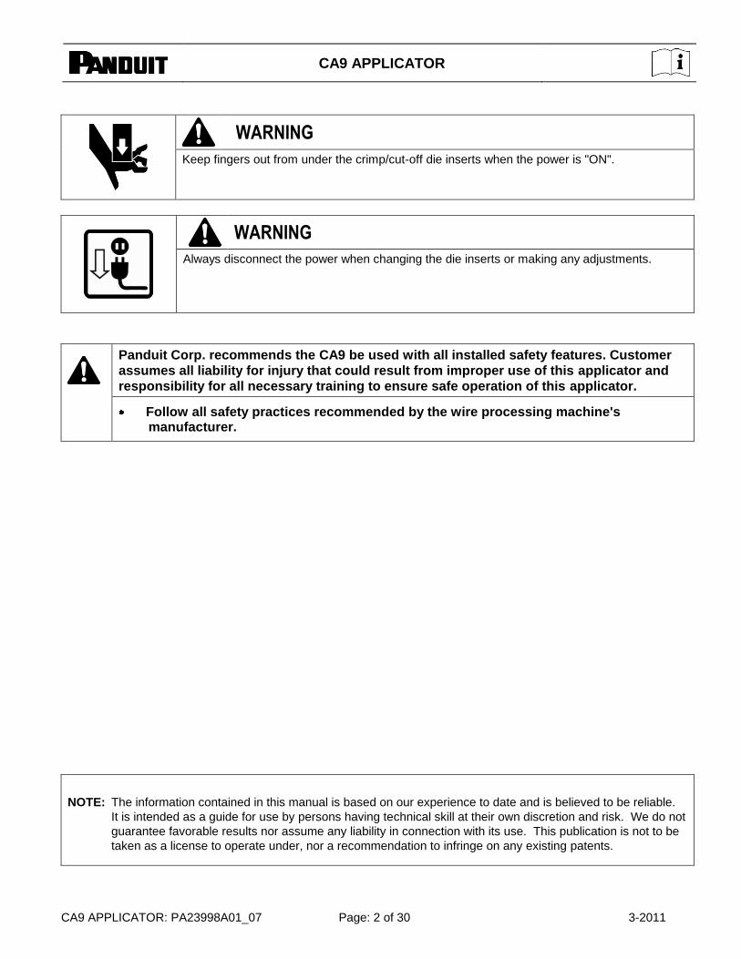
WARNING
Keep fingers out from under the crimp/cut-off die inserts when the power is "ON".
WARNING
Always disconnect the power when changing the die inserts or making any adjustments.
Panduit Corp. recommends the CA9 be used with all installed safety features. Customer
assumes all liability for injury that could result from improper use of this applicator and
responsibility for all necessary training to ensure safe operation of this applicator.
Follow all safety practices recommended by the wire processing machine's
manufacturer.
NOTE: The information contained in this manual is based on our experience to date and is believed to be reliable.
It is intended as a guide for use by persons having technical skill at their own discretion and risk. We do not
guarantee favorable results nor assume any liability in connection with its use. This publication is not to be
taken as a license to operate under, nor a recommendation to infringe on any existing patents.

CA9 APPLICATOR
CA9 APPLICATOR: PA23998A01_07 Page: 3 of 30 3-2011
WIRE PROCESSING MACHINE / PRESS COMPATIBILITY BY MANUFACTURER
Manufacturer
Wire Processing Machine w/Press (WPM)
or Bench Press only
Panduit Applicators
CA-800* CA-800EZ* CA9
PANDUIT
CP-851 Bench Press only A
CP-861 Bench Press only A
CP-862 Bench Press only A1
CP-871 Bench Press only A1
AMP
CLS III G w/G Press (WPM) A1
CLS IV w/G Press (WPM) A1
CLS IV Plus w/G Press (WPM) A1
G Bench Press only A1
CLS II w/T Press (WPM) A1
CLS III w/T Press (WPM) A1
T Bench Press only A A3
K Bench Press only A
ARTOS
CS-600 w/AMP G Press (WPM) A1
CS-600 w/TU-7M Press (WPM) A
CS-600 w/TU-10 Press (WPM) A1
MTX Series 5 w/TU-10 Press (WPM) A1
GAMMA
MECCANICA T20P-110V Bench Press only A1
KODERA
Series C451/C450 (WPM) A1
Series C551/C550 (WPM) A1
KOMAX
Gamma 311 w/Mecal K300 Press (WPM) B2 A1
Gamma 333 w/mci 711 Press (WPM) A1 Alpha 411 w/Mecal PE7 or P107 Press
(WPM) B2 A1
Alpha 433 w/Mecal PE7 or P107 Press (WPM)
A1
40T w/Mecal PE7 Press (WPM) A1
40T w/Panduit CP-861 Press (WPM) A
bt711 Bench Press only A4
MEGOMAT
ASM 3001A / APE 300 Press (WPM) A1
Contact (WPM) A1
Primo w/MP-3.0 Press (WPM) A1
MOLEX
EP-20 Bench Press only A
TM-2000 Bench Press only A
SCHLEUNIGER CrimpCenter 12 w/ACP 01 Press (WPM) A1
SHINMAYWA
TR101 (WPM) A
TRD111/TR111 (WPM) B A1
A = Best Choice (suited for particular application); B = Second Choice (also suited for particular application).
Special Requirements: *Refer to the specific applicator operation manual for installation instructions.
1 See specific section for installation details.
2 Komax press shim is required to operate CA-800EZ Applicator.
3 Bench press air feed capability is required.
4 Remove press wire stripper.
CA9 APPLICATOR
CA9 APPLICATOR: PA23998A01_07 Page: 4 of 30 3-2011
CA9 APPLICATOR
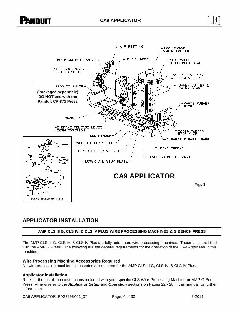
APPLICATOR INSTALLATION
AMP CLS III G, CLS IV, & CLS IV PLUS WIRE PROCESSING MACHINES & G BENCH PRESS
The AMP CLS III G, CLS IV, & CLS IV Plus are fully automated wire processing machines. These units are fitted with the AMP G Press. The following are the general requirements for the operation of the CA9 Applicator in this machine.
Wire Processing Machine Accessories Required No wire processing machine accessories are required for the AMP CLS III G, CLS IV, & CLS IV Plus.
Applicator Installation Refer to the installation instructions included with your specific CLS Wire Processing Machine or AMP G Bench Press. Always refer to the Applicator Setup and Operation sections on Pages 22 - 28 in this manual for further information.
Back View of CA9
Fig. 1
(Packaged separately)
DO NOT use with the
Panduit CP-871 Press

CA9 APPLICATOR
CA9 APPLICATOR: PA23998A01_07 Page: 5 of 30 3-2011
1. Turn ―OFF‖ the power to the terminating unit before installing the applicator. 2. Position the manual precision adjustment lever on the Model G terminating unit at the 00 mm (0.00 in) position
before installing the applicator. Verify that the terminating unit ram lock mechanism is in the ―unlocked" position and that the applicator base clamp is in the ―DOWN‖ position. The CA9 Applicator utilizes the press's standard shut height (5.348" or 135,8 mm). Therefore, no shut height changes are required for setup of the applicator. The ―G‖ Press shut height should be calibrated as stated in the Press Operation Manual.
3. Insert the applicator from the right, and slide it to the left until the unit base plate contacts the rear stops. While
moving the applicator to the left, pull ―UP‖ on the applicator ram until the shank collar is aligned with the groove of the terminating unit ram post adaptor. Continue moving the applicator to the left until the ram contacts the far left of the post adaptor.
4. Raise the applicator base clamp so that it is aligned in the keyway on the right edge of the applicator base.
Tighten the thumbscrew to lock the applicator base clamp in the keyway and lock the applicator in position. 5. Secure the applicator ram to the ram post adaptor by turning the thumbscrew for the ram lock mechanism
clockwise until tight. This will raise the applicator ram flush with the ram post adaptor. Verify that the applicator shank collar is aligned with the groove of the ram post adaptor.
6. Insert the air hose (included with the applicator) into the quick disconnect fitting of the air cylinder on the
applicator by supporting the fitting with your hand, and firmly inserting the hose into the fitting. 7. Connect the other end of the air hose to the normally open port of the G press air valve. Pull the toggle switch
on the applicator air cylinder to the ―ON‖ position. The applicator feed finger will shift forward when the toggle switch is turned ―ON‖.
NOTE: For proper applicator operation, the applicator air hose must be connected to the proper port (normally open port) of the press. If the air hose is connected to the press air valve, and the applicator air flow toggle switch is "ON", the feed finger should be positioned against the lower die front stop. If the feed finger is not positioned against the lower die front stop, the air hose may be connected to the wrong port of the press air valve.
Applicator Modifications Required No applicator modifications are required for the AMP CLS III G, CLS IV, & CLS IV Plus.
AMP CLS III G, CLS IV, & CLS IV PLUS Wire Processing Machine / G Press Settings 1. Set the G Press mode to ―Split Cycle‖. If you are using the G Press alone, skip Step 2 and advance to Step 3. 2. Operate the CLS Machine with the ―SHIFT‖ function activated. 3. Proceed to the Applicator Setup section on Page 22.
Die Insert Requirements The standard CD9 die inserts must be used.
AMP CLS II & CLS III WIRE PROCESSING MACHINES AND T BENCH PRESS
The AMP CLS II and CLS III are fully automated wire processing machines. These units are fitted with the AMP T Press. The following are the general requirements for the operation of the CA9 Applicator in these machines.
Wire Processing Machine Accessories Required No wire processing machine accessories are required for the AMP CLS II and CLS III.

CA9 APPLICATOR
CA9 APPLICATOR: PA23998A01_07 Page: 6 of 30 3-2011
Applicator Installation Refer to the installation instructions included with your CLS II and CLS III Wire Processing Machines or AMP T Bench Press. Always refer to the Applicator Setup and Operation sections on Pages 22 - 28 in this manual for further information.
NOTE: The AMP T press must be equipped with a Quick Change type base plate for the CA9 Applicator to be installed.
1. Turn ―OFF‖ the power to the terminating unit before installing the applicator. 2. Push the Release Bar on the Quick Change base plate ―IN‖. The locking latch can now pivot downward. 3. Insert the applicator from the right, and slide it to the left until the base plate contacts the rear stops. While
moving the applicator to left, pull ―UP‖ on the applicator ram until the shank collar is aligned with the grove of the terminating unit ram post adapter.
4. Flip the locking latch on the press base plate ―UP‖ to lock the applicator in position. 5. Insert the air hose (included with the applicator) into the quick disconnect fitting of the air cylinder on the
applicator by supporting the fitting with your hand, and firmly inserting the hose into the fitting. 6. Connect the other end of the air hose to the normally open port of the T press air valve. Pull the toggle switch
on the applicator air cycling to the ―ON‖ position. The applicator feed finger will shift forward when the toggle switch is turned ―ON‖.
NOTE: For proper applicator operation, the applicator air hose must be connected to the proper port (normally open port) of the press. If the air hose is connected to the press air valve, and the applicator air flow toggle switch is ―ON‖, the feed finger should be positioned against the lower die front stop. If the feed finger is not positioned against the lower die front stop, the air hose may be connected to the wrong port of the press air valve.
Applicator Modifications Required No applicator modifications are required for the AMP CLS II and CLS III.
AMP CLS II and CLS III Wire Processing Machine / T Press Settings 1. Set the T Press mode to ―Split Cycle‖. If you are using the T Press alone, skip Step 2 and advance to Step 3. 2. Operate the CLS Machine with the ―SHIFT‖ function activated. 3. Proceed to the Applicator Setup Section on Page 22.
Die Insert Requirements The standard CD9 die inserts must be used.
ARTOS CS-600 WIRE PROCESSING MACHINE WITH AMP G PRESS
The Artos CS-600 is a fully automated wire processing machine. This unit is typically fitted with the Artos TU-7M or AMP G crimp terminating press. This application requirement is for a CS-600 with AMP G press. The following are the general requirements for the operation of the CA9 Applicator in this machine.
Wire Processing Machine Accessories Required For the CA9 Applicator to work in the CS-600, the machine must be equipped with the pneumatic controls capable of running the applicator. These controls come standard on the AMP G press. The air valve used to control the applicator is mounted on the press. The applicator performs best when the wire processing machine runs with the press in the split cycle mode.
CA9 APPLICATOR
CA9 APPLICATOR: PA23998A01_07 Page: 7 of 30 3-2011
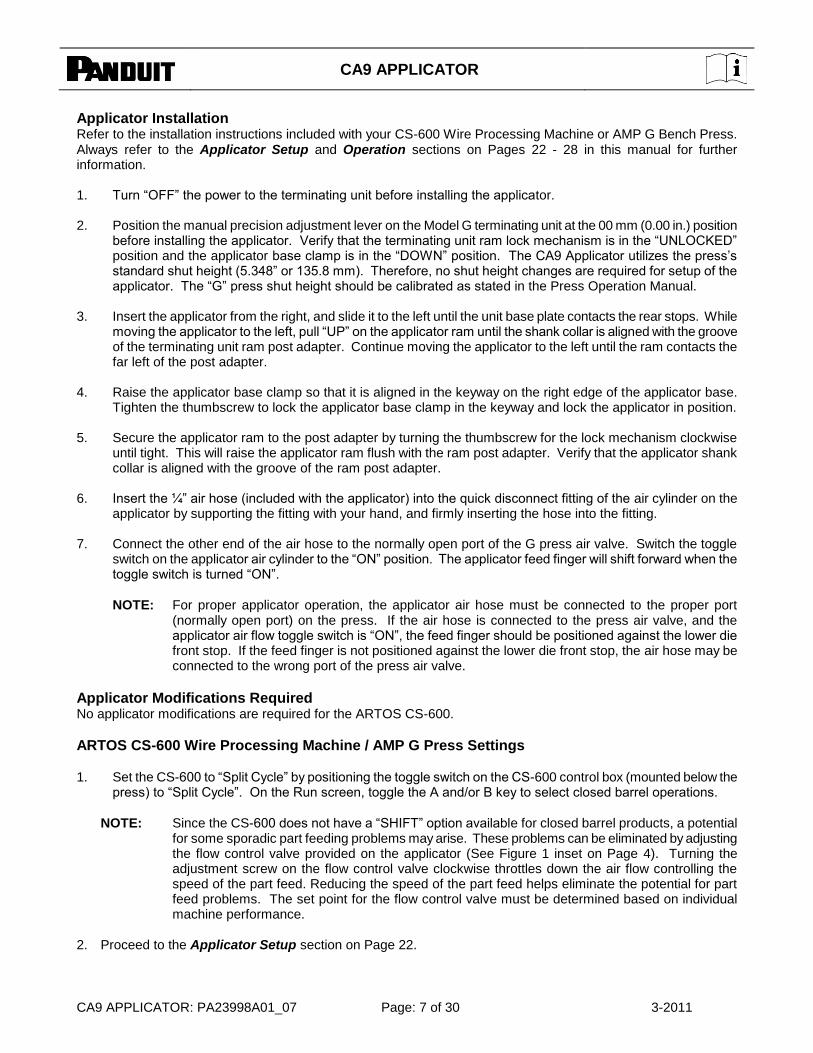
Applicator Installation Refer to the installation instructions included with your CS-600 Wire Processing Machine or AMP G Bench Press. Always refer to the Applicator Setup and Operation sections on Pages 22 - 28 in this manual for further information. 1. Turn ―OFF‖ the power to the terminating unit before installing the applicator. 2. Position the manual precision adjustment lever on the Model G terminating unit at the 00 mm (0.00 in.) position
before installing the applicator. Verify that the terminating unit ram lock mechanism is in the ―UNLOCKED‖ position and the applicator base clamp is in the ―DOWN‖ position. The CA9 Applicator utilizes the press’s standard shut height (5.348‖ or 135.8 mm). Therefore, no shut height changes are required for setup of the applicator. The ―G‖ press shut height should be calibrated as stated in the Press Operation Manual.
3. Insert the applicator from the right, and slide it to the left until the unit base plate contacts the rear stops. While
moving the applicator to the left, pull ―UP‖ on the applicator ram until the shank collar is aligned with the groove of the terminating unit ram post adapter. Continue moving the applicator to the left until the ram contacts the far left of the post adapter.
4. Raise the applicator base clamp so that it is aligned in the keyway on the right edge of the applicator base.
Tighten the thumbscrew to lock the applicator base clamp in the keyway and lock the applicator in position. 5. Secure the applicator ram to the post adapter by turning the thumbscrew for the lock mechanism clockwise
until tight. This will raise the applicator ram flush with the ram post adapter. Verify that the applicator shank collar is aligned with the groove of the ram post adapter.
6. Insert the ¼‖ air hose (included with the applicator) into the quick disconnect fitting of the air cylinder on the
applicator by supporting the fitting with your hand, and firmly inserting the hose into the fitting. 7. Connect the other end of the air hose to the normally open port of the G press air valve. Switch the toggle
switch on the applicator air cylinder to the ―ON‖ position. The applicator feed finger will shift forward when the toggle switch is turned ―ON‖.
NOTE: For proper applicator operation, the applicator air hose must be connected to the proper port (normally open port) on the press. If the air hose is connected to the press air valve, and the applicator air flow toggle switch is ―ON‖, the feed finger should be positioned against the lower die front stop. If the feed finger is not positioned against the lower die front stop, the air hose may be connected to the wrong port of the press air valve.
Applicator Modifications Required No applicator modifications are required for the ARTOS CS-600.
ARTOS CS-600 Wire Processing Machine / AMP G Press Settings 1. Set the CS-600 to ―Split Cycle‖ by positioning the toggle switch on the CS-600 control box (mounted below the
press) to ―Split Cycle‖. On the Run screen, toggle the A and/or B key to select closed barrel operations.
NOTE: Since the CS-600 does not have a ―SHIFT‖ option available for closed barrel products, a potential for some sporadic part feeding problems may arise. These problems can be eliminated by adjusting the flow control valve provided on the applicator (See Figure 1 inset on Page 4). Turning the adjustment screw on the flow control valve clockwise throttles down the air flow controlling the speed of the part feed. Reducing the speed of the part feed helps eliminate the potential for part feed problems. The set point for the flow control valve must be determined based on individual machine performance.
2. Proceed to the Applicator Setup section on Page 22.
CA9 APPLICATOR
CA9 APPLICATOR: PA23998A01_07 Page: 8 of 30 3-2011
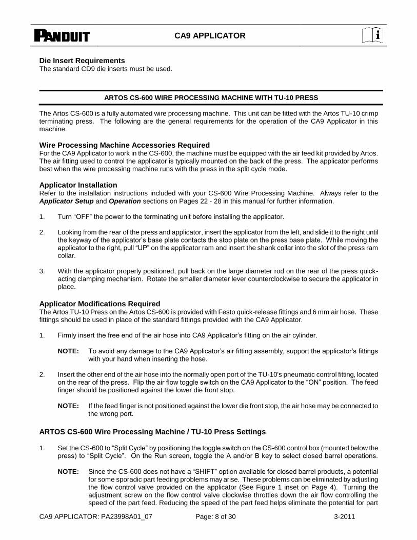
Die Insert Requirements The standard CD9 die inserts must be used.
ARTOS CS-600 WIRE PROCESSING MACHINE WITH TU-10 PRESS
The Artos CS-600 is a fully automated wire processing machine. This unit can be fitted with the Artos TU-10 crimp terminating press. The following are the general requirements for the operation of the CA9 Applicator in this machine.
Wire Processing Machine Accessories Required For the CA9 Applicator to work in the CS-600, the machine must be equipped with the air feed kit provided by Artos. The air fitting used to control the applicator is typically mounted on the back of the press. The applicator performs best when the wire processing machine runs with the press in the split cycle mode.
Applicator Installation Refer to the installation instructions included with your CS-600 Wire Processing Machine. Always refer to the Applicator Setup and Operation sections on Pages 22 - 28 in this manual for further information. 1. Turn ―OFF‖ the power to the terminating unit before installing the applicator. 2. Looking from the rear of the press and applicator, insert the applicator from the left, and slide it to the right until
the keyway of the applicator’s base plate contacts the stop plate on the press base plate. While moving the applicator to the right, pull ―UP‖ on the applicator ram and insert the shank collar into the slot of the press ram collar.
3. With the applicator properly positioned, pull back on the large diameter rod on the rear of the press quick-
acting clamping mechanism. Rotate the smaller diameter lever counterclockwise to secure the applicator in place.
Applicator Modifications Required The Artos TU-10 Press on the Artos CS-600 is provided with Festo quick-release fittings and 6 mm air hose. These fittings should be used in place of the standard fittings provided with the CA9 Applicator. 1. Firmly insert the free end of the air hose into CA9 Applicator’s fitting on the air cylinder.
NOTE: To avoid any damage to the CA9 Applicator’s air fitting assembly, support the applicator’s fittings with your hand when inserting the hose.
2. Insert the other end of the air hose into the normally open port of the TU-10's pneumatic control fitting, located
on the rear of the press. Flip the air flow toggle switch on the CA9 Applicator to the ―ON‖ position. The feed finger should be positioned against the lower die front stop.
NOTE: If the feed finger is not positioned against the lower die front stop, the air hose may be connected to the wrong port.
ARTOS CS-600 Wire Processing Machine / TU-10 Press Settings
1. Set the CS-600 to ―Split Cycle‖ by positioning the toggle switch on the CS-600 control box (mounted below the
press) to ―Split Cycle‖. On the Run screen, toggle the A and/or B key to select closed barrel operations.
NOTE: Since the CS-600 does not have a ―SHIFT‖ option available for closed barrel products, a potential for some sporadic part feeding problems may arise. These problems can be eliminated by adjusting the flow control valve provided on the applicator (See Figure 1 inset on Page 4). Turning the adjustment screw on the flow control valve clockwise throttles down the air flow controlling the speed of the part feed. Reducing the speed of the part feed helps eliminate the potential for part
CA9 APPLICATOR
CA9 APPLICATOR: PA23998A01_07 Page: 9 of 30 3-2011
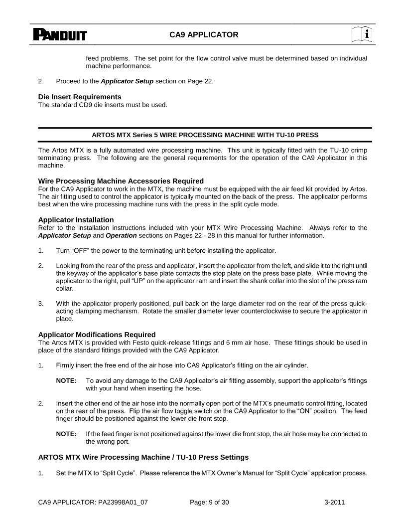
feed problems. The set point for the flow control valve must be determined based on individual machine performance.
2. Proceed to the Applicator Setup section on Page 22.
Die Insert Requirements The standard CD9 die inserts must be used.
ARTOS MTX Series 5 WIRE PROCESSING MACHINE WITH TU-10 PRESS
The Artos MTX is a fully automated wire processing machine. This unit is typically fitted with the TU-10 crimp terminating press. The following are the general requirements for the operation of the CA9 Applicator in this machine.
Wire Processing Machine Accessories Required For the CA9 Applicator to work in the MTX, the machine must be equipped with the air feed kit provided by Artos. The air fitting used to control the applicator is typically mounted on the back of the press. The applicator performs best when the wire processing machine runs with the press in the split cycle mode.
Applicator Installation Refer to the installation instructions included with your MTX Wire Processing Machine. Always refer to the Applicator Setup and Operation sections on Pages 22 - 28 in this manual for further information. 1. Turn ―OFF‖ the power to the terminating unit before installing the applicator. 2. Looking from the rear of the press and applicator, insert the applicator from the left, and slide it to the right until
the keyway of the applicator’s base plate contacts the stop plate on the press base plate. While moving the applicator to the right, pull ―UP‖ on the applicator ram and insert the shank collar into the slot of the press ram collar.
3. With the applicator properly positioned, pull back on the large diameter rod on the rear of the press quick-
acting clamping mechanism. Rotate the smaller diameter lever counterclockwise to secure the applicator in place.
Applicator Modifications Required The Artos MTX is provided with Festo quick-release fittings and 6 mm air hose. These fittings should be used in place of the standard fittings provided with the CA9 Applicator. 1. Firmly insert the free end of the air hose into CA9 Applicator’s fitting on the air cylinder.
NOTE: To avoid any damage to the CA9 Applicator’s air fitting assembly, support the applicator’s fittings with your hand when inserting the hose.
2. Insert the other end of the air hose into the normally open port of the MTX’s pneumatic control fitting, located
on the rear of the press. Flip the air flow toggle switch on the CA9 Applicator to the ―ON‖ position. The feed finger should be positioned against the lower die front stop.
NOTE: If the feed finger is not positioned against the lower die front stop, the air hose may be connected to the wrong port.
ARTOS MTX Wire Processing Machine / TU-10 Press Settings
1. Set the MTX to ―Split Cycle‖. Please reference the MTX Owner’s Manual for ―Split Cycle‖ application process.
CA9 APPLICATOR
CA9 APPLICATOR: PA23998A01_07 Page: 10 of 30 3-2011
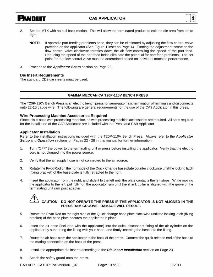
2. Set the MTX with no pull back motion. This will allow the terminated product to exit the die area from left to right.
NOTE: If sporadic part feeding problems arise, they can be eliminated by adjusting the flow control valve provided on the applicator (See Figure 1 inset on Page 4). Turning the adjustment screw on the flow control valve clockwise throttles down the air flow controlling the speed of the part feed. Reducing the speed of the part feed helps eliminate the potential for part feed problems. The set point for the flow control valve must be determined based on individual machine performance.
3. Proceed to the Applicator Setup section on Page 22.
Die Insert Requirements The standard CD9 die inserts must be used.
GAMMA MECCANICA T20P-110V BENCH PRESS
The T20P-110V Bench Press is an electric bench press for semi-automatic termination of terminals and disconnects onto 22-10 gauge wire. The following are general requirements for the use of the CA9 Applicator in this press.
Wire Processing Machine Accessories Required Since this is not a wire processing machine, no wire processing machine accessories are required. All parts required for the installation of the CA9 Applicator are included with the Press and CA9 Applicator.
Applicator Installation
Refer to the installation instructions included with the T20P-110V Bench Press. Always refer to the Applicator Setup and Operation sections on Pages 22 - 28 in this manual for further information. 1. Turn ―OFF‖ the power to the terminating unit or press before installing the applicator. Verify that the electric
cord is not plugged into the power source. 2. Verify that the air supply hose is not connected to the air source. 3. Rotate the Pivot Rod on the right side of the Quick Change base plate counter clockwise until the locking latch
(fixing bracket) of the base plate is fully retracted to the right. 4. Insert the applicator from the right, and slide it to the left until the plate contacts the left stops. While moving
the applicator to the left, pull ―UP‖ on the applicator ram until the shank collar is aligned with the grove of the terminating unit ram post adapter.
CAUTION: DO NOT OPERATE THE PRESS IF THE APPLICATOR IS NOT ALIGNED IN THE
PRESS RAM GROOVE. DAMAGE WILL RESULT.
5. Rotate the Pivot Rod on the right side of the Quick change base plate clockwise until the locking latch (fixing bracket) of the base plate secures the applicator in place.
6. Insert the air hose (included with the applicator) into the quick disconnect fitting of the air cylinder on the
applicator by supporting the fitting with your hand, and firmly inserting the hose into the fitting. 7. Route the air hose from the applicator to the back of the press. Connect the quick release end of the hose to
the mating connection on the back of the press. 8. Install the appropriate die inserts according to the Die Insert Installation section on Page 23. 9. Attach the safety guard onto the press.
CA9 APPLICATOR
CA9 APPLICATOR: PA23998A01_07 Page: 11 of 30 3-2011
10. Plug in the press. Connect the main airline connection to the fitting on the rear of the press.
Applicator Modifications Required No applicator modifications are required for the CA9 to operate in the T20P-110V press.
T20P-110V Bench Press Settings Refer to the T20P-110V Bench Press Operation Manual for operation. No special settings are required to operate
the T20P-110V press. Proceed to the Applicator Setup section on Page 22.
Die Insert Requirements The standard CD9 die inserts must be used.
KODERA SERIES C451/C450 & C551/C550 WIRE PROCESSING MACHINES
The Kodera Series C451/C450 and C551/C550 are fully automated crimping machines. The following are the general requirements for use of the CA9 Applicator in these machines.
Wire Processing Machine Accessories Required For the CA9 Applicator to work in a Kodera Wire Processing Machine, the machine must be equipped with the AFA Air Feed Kit, a One Touch Base Plate (Part #23), and the Software (ROM) for the Panduit CA9 Applicator (specify your Kodera machine when ordering). All these accessories are provided by Kodera. The AFA Air Feed Kit consists of a solenoid valve, solenoid mounting harness, and air hose. For additional information on the Kodera AFA Air Feed Kit, One Touch Base Plate (Part #23), or the specific Software (ROM) required, contact Kodera Electronics Co.
Applicator Installation Refer to the installation instructions included with your Kodera Wire Processing Machine. Always refer to the Applicator Setup and Operation sections on Pages 22 - 28 in this manual for further information.
1. Turn ―OFF‖ the power to the terminating unit before installing the applicator. 2. Insert the applicator into the press. While positioning the applicator, pull ―UP‖ on the applicator ram and insert
its shank collar into the slot of the press ram collar. 3. With the applicator properly positioned, secure the applicator base in place. 4. Verify that the proper software (ROM) is being used for the specific press series used (C451 or C551). 5. Insert the air hose into the air fitting on applicator.
NOTE: For proper applicator operation, the applicator air hose must be connected to the proper port (normally open) of the air feed kit. If the air hose is connected to the air feed kit air valve, and the applicator air flow toggle switch is ―ON‖, the feed finger should be positioned against the lower die front stop. If the feed finger is not positioned against the lower die front stop, the air hose may be connected to the wrong port of the air feed kit air valve.
Applicator Modifications Required No applicator modifications are required for the Kodera Wire Processing Machines.
KODERA C451/C450 and C551/C550 Wire Processing Machine Settings
Proceed to the Applicator Setup section on Page 22.
Die Insert Requirements The standard CD9 die inserts must be used.

CA9 APPLICATOR
CA9 APPLICATOR: PA23998A01_07 Page: 12 of 30 3-2011
KOMAX GAMMA 311 WIRE PROCESSING MACHINE WITH MECAL K300 PRESS
The Komax Gamma 311 is a fully automated wire processing machine. This unit is typically fitted with the Mecal K300 crimp terminating press. The following are the general requirements for use of the CA9 Applicator in this machine.
Wire Processing Machine Accessories Required For the CA9 Applicator to work in the 311, the machine must be equipped with the Air Feed Kit provided by Komax. The kit consists of a solenoid valve, timing controls and activation controls. The solenoid valve is typically mounted to the press and the activation controls are typically mounted on the main control panel of the 311. The air feed kit can be set up for either split cycle or full cycle operation. When using the CA9 Applicator in the 311, split cycle operation should be used. For additional information on the Gamma Air Feed Kit, contact Komax Corporation.
Applicator Installation Refer to the installation instructions included with your 311 Wire Processing Machine or Mecal K300 Press. Always refer to the Applicator Setup and Operation sections on Pages 22 - 28 in this manual for further information. 1. Turn ―OFF‖ the power to the terminating unit before installing the applicator. 2. Insert the applicator from the left and slide it to the right until the keyway of the CA9 Applicator’s base plate
contacts the stop clamp on the press base plate. While moving the applicator to the right, pull ―UP‖ on the applicator ram and insert its shank collar into the slot of the press ram collar.
3. With the applicator properly positioned, lift up the lever of the press quick-acting clamping mechanism to
secure the applicator in place.
Applicator Modifications Required The 311 Air Feed Kit solenoid is equipped with 4mm metric hose fittings to control the air feed of pneumatic applicators. The standard air fitting on the CA9 Applicator is ¼‖. Therefore, a Hose Adapter Assembly (Panduit Part Number KHCA9), provided by Panduit, must be used to operate the CA9 Applicator in the 311. This is accomplished as follows: 1. Remove the ¼‖ x 5/32‖ (4 mm) Hose Adapter Assembly (Panduit Part Number KHCA9 - plastic hose adapter
and 4mm hose) from its packaging. 2. Firmly insert the male portion of the adapter into the CA9 Applicator’s fitting on the air cylinder.
NOTE: To avoid any damage to the CA9 Applicator’s air fitting assembly, support the applicator’s fitting with your hand when inserting the hose adapter.
3. Insert the other end of the hose into the normally open port of the 311’s pneumatic applicator control fitting.
This is located on the 311’s Air Feed Kit solenoid valve. With the applicator connected in this fashion and the air flow toggle switch of the CA9 Applicator in the ―ON‖ position, the feed finger should be positioned against the lower die front stop (Note: If the feed finger is not positioned against the lower die front stop, the air hose may be connected to the wrong port).
CAUTION: As stated above, the CA9 Applicator’s air hose must be connected to the normally
open control port of the 311’s solenoid valve. Depending on the machine setup,
this port may be plugged and the normally closed port may have the only fitting. If
this is the case, the fitting must be changed to allow connection to the normally
open port. Before switching these fittings, ensure that the air pressure at the
connection has been relieved.

CA9 APPLICATOR
CA9 APPLICATOR: PA23998A01_07 Page: 13 of 30 3-2011
KOMAX Gamma 311 Wire Processing Machine / MECAL K300 Press Settings
1. Make cam adjustments for ―Split Cycle‖ operation per Komax instructions. 2. Proceed to the Applicator Setup section on Page 22.
NOTE: If the 311 machine is shut down for any reason in the above configuration, the operator must manually crank the press, to move the press ram to the top of its stroke (in split cycle mode, the press ram’s ―rest‖ state is in the down position). This is done to avoid parts being feed into the crimp area with the applicator ram down. If the CA9 Applicator’s ram is down, parts cannot feed into the crimp area and part jams will occur.
Die Insert Requirements The standard CD9 die inserts must be used.
KOMAX GAMMA 333 OR ALPHA 433 WIRE PROCESSING MACHINE WITH MCI 711 PRESS
The Komax Gamma 333 or Alpha 433 is a fully automated wire processing machine. This unit is typically fitted with Komax mci 711 crimp terminating press. The following are the general requirements for use of the CA9 Applicator in this machine.
Wire Processing Machine Accessories Required For the CA9 Applicator to work in the 333 or 433, the machine must be equipped with the pneumatic components capable of running the applicator, which is standard. To aid the accuracy of wire insertion into the product barrel (on the leading end of the machine), Komax offers interchangeable wire guide tubes. The proper guide tubes minimizes the wire overhang from the feed mechanism to the applicator crimp area. This allows the precise placement of the wire into the product barrel. The guide tubes which provides the most support for the wire without interfering with the applicator should be used when operating the CA9 Applicator. For the trailing end, there is a funnel kit available from Komax that will provide more accurate wire targeting. For additional information on the above accessories, contact Komax Corporation.
Applicator Installation Refer to the installation instructions included with your Komax Wire Processing Machine or MCI 711 Press. Always refer to the Applicator Setup and Operation sections on Pages 22 - 28 in this manual for further information. 1. Turn ―OFF‖ the power to the terminating unit before installing the applicator. 2. Insert the applicator from the left and slide it to the right until the keyway of the CA9 Applicator’s base plate
contacts the stop clamp on the press base plate. While moving the applicator to the right, pull ―UP‖ on the applicator ram and insert its shank collar into the slot of the press ram collar.
3. With the applicator properly positioned, lift up the lever of the press quick-acting clamping mechanism to
secure the applicator in place.
Applicator Modifications Required The 333 or 433 is equipped with 4mm metric hose fittings to control the air feed of pneumatic applicators. The standard air fitting on the CA9 Applicator is ¼‖. Therefore, a hose adapter assembly (Panduit Part Number KHCA9), provided by Panduit, must be used to operate the CA9 Applicator in this equipment. This is accomplished as follows: 1. Remove the ¼‖ x 5/32‖ (4 mm) hose adapter assembly (Panduit Part Number KHCA9 - plastic hose adapter
and 4mm hose) from its packaging.
CA9 APPLICATOR
CA9 APPLICATOR: PA23998A01_07 Page: 14 of 30 3-2011
2. Firmly insert the male portion of the adapter into the CA9 Applicator’s fitting on the air cylinder.
NOTE: To avoid any damage to the CA9 Applicator’s air fitting assembly, support the applicator’s fitting with your hand when inserting the hose adapter.
3. Insert the other end of the hose into the normally open port of the wire processing machine’s control fitting. With the applicator connected in this fashion and the air flow toggle switch of the CA9 Applicator ―ON‖, the feed finger should be positioned against the lower die front stop.
NOTE: If the feed finger is not positioned against the lower die front stop, the air hose may be connected to the wrong port.
CAUTION: As stated above, the CA9 Applicator’s air hose must be connected to the normally
open control port of the wire processing machine’s solenoid valve. Depending on
the machine setup, this port may be plugged and the normally closed port may
have the only fitting. If this is the case, the fitting must be changed to allow
connection to the normally open port. Before switching these fittings, ensure that
the air pressure at the connection has been relieved.
KOMAX Gamma 333 or Alpha 433 Wire Processing Machine / MCI 711 Press Settings
1. Set the MCI 711 Press mode to ―Split Cycle‖ and follow the Komax air feed procedure. With the press set in split cycle mode and the applicator’s air cylinder connected to the normally open port of the wire processing machine’s control port, the CA9 Applicator is ready for operation.
2. Proceed to the Applicator Setup section on Page 19.
NOTE: If the 333 or 433 machine is shut down for any reason in the above configuration, the operator must use OMI (Operator Manual Interface) to move the press ram to the top of its stroke (in split cycle, the press ram’s ―rest‖ state is in the down position). This is done to avoid parts being fed into the crimp area with the applicator ram down. If the CA9 Applicator’s ram is down, parts cannot feed into the crimp area and part jams will occur.
Die Insert Requirements The standard CD9 die inserts must be used.
KOMAX ALPHA 411 WIRE PROCESSING MACHINE WITH MECAL PE7 OR P107 PRESS
The Komax Alpha 411 is a fully automated crimping machine. This unit is typically fitted with the Mecal PE7 or P107 crimp terminating press. The following are the general requirements for use of the CA9 Applicator in this machine.
Wire Processing Machine Accessories Required For the CA9 Applicator to work in the 411, the machine must be equipped with the Air Feed Kit provided by Komax. The kit consists of a solenoid valve, timing controls and activation controls. The solenoid valve is typically mounted to the press and the activation controls are software driven. The air feed kit can be set up for either split cycle or full cycle operation. When using the CA9 Applicator in the 411, split cycle operation should be used. To aid the accuracy of wire insertion into the product barrel (on the leading end of the machine), Komax offers interchangeable wire guide tubes. The proper guide tube minimizes the wire overhang from the feed mechanism to the applicator crimp area. This allows the precise placement of the wire into the product barrel. The guide tube which provides the most support for the wire without interfering with the applicator should be used when operating the CA9 Applicator in the 411. For additional information on the 411 Air Feed Kit and wire guide tubes, contact Komax Corporation.
CA9 APPLICATOR
CA9 APPLICATOR: PA23998A01_07 Page: 15 of 30 3-2011
Applicator Installation Refer to the installation instructions included with your 411 Wire Processing Machine or Mecal PE7 or P107 Press. Always refer to the Applicator Setup and Operation sections on Pages 22 - 28 in this manual for further information.
1. Turn ―OFF‖ the power to the terminating unit before installing the applicator. 2. Insert the applicator from the left and slide it to the right until the keyway of the CA9 Applicator’s base plate
contacts the stop clamp on the press base plate. While moving the applicator to the right, pull ―UP‖ on the applicator ram and insert its shank collar into the slot of the press ram collar.
3. With the applicator properly positioned, screw in the single tooth locking mechanism to secure the applicator in
place.
Applicator Modifications Required
1. The CA9 Applicator comes with a 1/4" hose with a quick release coupling. This coupling must be removed
from the hose, to allow the hose to be inserted into the 411 machine. This can be accomplished by using a small wrench or by cutting the hose at the base of the coupling.
2. Firmly insert the hose into the CA9 Applicator’s fitting on the air cylinder.
NOTE: To avoid any damage to the CA9 Applicator’s air fitting assembly, support the applicator’s fitting with your hand when inserting the hose.
3. Insert the other end of the hose into the normally open port of the 411’s control fitting. This is located on the
411’s Air Feed Kit solenoid valve. With the applicator connected in this fashion and the air flow toggle switch of the CA9 Applicator in the ―ON‖ position, the feed finger should be positioned against the lower die front stop. If the feed finger is not positioned against the lower die front stop, the air hose may be connected to the wrong port.
NOTE: As stated above, the CA9 Applicator’s air hose must be connected to the normally open control port of the 411’s solenoid valve. Depending on the machine setup, this port may be plugged and the normally closed port may have the only fitting. If this is the case, the fitting must be changed to allow connection to the normally open port. Before switching these fittings, ensure that the air pressure at the connection has been relieved.
KOMAX ALPHA 411 Wire Processing Machine / Mecal PE7 or P107 Press Settings 1. Set the MECAL PE7 or P107 Press mode to ―Split Cycle‖. 2. Proceed to the Applicator Setup section on Page 22.
NOTE: If the 411 machine is shut down for any reason in the above configuration, the operator must manually crank the press, to move the press ram to the top of its stroke (in split cycle mode, the press ram’s ―rest‖ state is in the down position). This is done to avoid parts being feed into the crimp area with the applicator ram down. If the CA9 Applicator’s ram is down, parts cannot feed into the crimp area and part jams will occur.
Die Insert Requirements The standard CD9 die inserts must be used.
CA9 APPLICATOR
CA9 APPLICATOR: PA23998A01_07 Page: 16 of 30 3-2011
KOMAX 40T WIRE PROCESSING MACHINE WITH MECAL PE7 PRESS
The Komax 40T is a fully automated crimping machine. This unit is typically fitted with the Mecal PE7 crimp terminating press. The following are the general requirements for use of the CA9 Applicator in this machine.
Wire Processing Machine Accessories Required For the CA9 Applicator to work in the 40T, the machine must be equipped with the Air Feed Kit provided by Komax. The kit consists of a solenoid valve, timing controls and activation controls. The solenoid valve is typically mounted to the press and the activation controls are software driven. The air feed kit can be set up for either split cycle or full cycle operation. When using the CA9 Applicator in the 40T, split cycle operation should be used. To aid the accuracy of wire insertion into the product barrel (on the leading end of the machine), Komax offers interchangeable wire guide tubes. The proper guide tube minimizes the wire overhang from the feed mechanism to the applicator crimp area. This allows the precise placement of the wire into the product barrel. The guide tube which provides the most support for the wire without interfering with the applicator should be used when operating the CA9 Applicator in the 40T. For additional information on the 40T Air Feed Kit and wire guide tubes, contact Komax Corporation.
Applicator Installation Refer to the installation instructions included with your 40T Wire Processing Machine or Mecal PE7 Press. Always refer to the Applicator Setup and Operation sections on Pages 22 - 28 in this manual for further information.
1. Turn ―OFF‖ the power to the terminating unit before installing the applicator. 2. Insert the applicator from the left and slide it to the right until the keyway of the CA9 Applicator’s base plate
contacts the stop clamp on the press base plate. While moving the applicator to the right, pull ―UP‖ on the applicator ram and insert its shank collar into the slot of the press ram collar.
3. With the applicator properly positioned, screw in the single tooth locking mechanism to secure the applicator in
place.
Applicator Modifications Required
1. The CA9 Applicator comes with a 1/4" hose with a quick release coupling. This coupling must be removed
from the hose, to allow the hose to be inserted into the 40T machine. This can be accomplished by using a small wrench or by cutting the hose at the base of the coupling.
2. Firmly insert the hose into the CA9 Applicator’s fitting on the air cylinder.
NOTE: To avoid any damage to the CA9 Applicator’s air fitting assembly, support the applicator’s fitting with your hand when inserting the hose.
3. Insert the other end of the hose into the normally open port of the 40T’s control fitting. This is located on the
40T’s Air Feed Kit solenoid valve. With the applicator connected in this fashion and the air flow toggle switch of the CA9 Applicator in the ―ON‖ position, the feed finger should be positioned against the lower die front stop. If the feed finger is not positioned against the lower die front stop, the air hose may be connected to the wrong port.
NOTE: As stated above, the CA9 Applicator’s air hose must be connected to the normally open control port of the 40T’s solenoid valve. Depending on the machine setup, this port may be plugged and the normally closed port may have the only fitting. If this is the case, the fitting must be changed to allow connection to the normally open port. Before switching these fittings, ensure that the air pressure at the connection has been relieved.
CA9 APPLICATOR
CA9 APPLICATOR: PA23998A01_07 Page: 17 of 30 3-2011
KOMAX 40T Wire Processing Machine / Mecal PE7 Press Settings 1. Set the MECAL PE7 or P107 Press mode to ―Split Cycle‖. 2. Proceed to the Applicator Setup section on Page 22.
NOTE: If the 40T machine is shut down for any reason in the above configuration, the operator must manually crank the press, to move the press ram to the top of its stroke (in split cycle mode, the press ram’s ―rest‖ state is in the down position). This is done to avoid parts being feed into the crimp area with the applicator ram down. If the CA9 Applicator’s ram is down, parts cannot feed into the crimp area and part jams will occur.
Die Insert Requirements The standard CD9 die inserts must be used.
MEGOMAT ASM 3001A & PRIMO WIRE PROCESSING MACHINES
The Megomat ASM3001A and Primo are fully automated wire processing machines. The Megomat ASM3001A is typically fitted with the Megomat APE300 terminating press, and the Primo is typically fitted with the Megomat MP-3.0 terminating press. The following are the general requirements for the use of the CA9 Applicator in these machines.
Wire Processing Machine Accessories Required The ASM3001A and Primo machines must be equipped with an Air Feed Kit provided by Megomat. The kit consists of a solenoid air valve and the necessary components to integrate it into the machine. No software changes are required to operate the air feed kit. They are all preprogrammed into the machines standard software.
Applicator Installation Refer to the installation instructions included with your exact wire processing machine and press. Always refer to the Applicator Setup and Operation sections on Pages 22 - 28 in this manual for further information. 1. Turn ―OFF‖ the power to the terminating unit before installing the applicator. 2. Insert the applicator into the press by inserting the applicator ram’s shank collar into the slot on the press ram
collar. Slide the applicator onto the press base plate until it contacts the stop clamps on the press base plate. 3. With the applicator properly positioned, secure the applicator in place with the locking mechanism on the press
base plate. 4. Insert the 6mm air hose supplied with the Megomat wire processing machine air feed kit into the quick
disconnect fitting of the CA9 Applicator air cylinder by supporting the fitting with your hand, and firmly inserting the hose into the fitting.
5. Connect the other end of the air hose to the normally open port of the wire processing machine control valve.
Pull the toggle switch on the applicator air cylinder to the ―ON‖ position. The applicator feed finger will shift forward when the toggle switch is turned ―ON‖.
NOTE: For proper applicator operation, the applicator air hose must be connected to the proper port (normally open) of the air feed kit. If the air hose is connected to the air feed kit air valve, and the applicator air flow toggle switch is ―ON‖, the feed finger should be positioned against the lower die front stop. If the feed finger is not positioned against the lower die front stop, the air hose may be connected to the wrong port of the air feed kit air valve.
Applicator Modifications Required No applicator modifications are required for the Megomat Wire Processing Machines.
CA9 APPLICATOR
CA9 APPLICATOR: PA23998A01_07 Page: 18 of 30 3-2011
MEGOMAT Wire Processing Machine / Press Settings
1. Set the press mode to ―Split Cycle‖ by setting the selector switch on the back of the press (Set to number 7 for the ASM 3001A/APE 300, and set to ―Split Cycle‖ for the Primo/MP-3.0).
2. Press the reset switch on the back of the press to rotate the press to the proper split cycle position. 3. Proceed to the Applicator Setup section on Page 22.
Die Insert Requirements The standard CD9 die inserts must be used.
Panduit CP-862 BENCH PRESS
The CP-862 Bench Press is an electric bench press for semi-automatic termination of terminals and disconnects onto 22-10 gauge wire. The following are the general requirements for the use of the CA9 Applicator in this press.
Wire Processing Machine Accessories Required Since this is not a wire processing machine, no wire processing machine accessories are required. All parts required for the installation of the CA9 Applicator are included with the Panduit CP-862 Press and CA9 Applicator.
Applicator Installation
Refer to the installation instructions included with your CP-862 Bench Press. Always refer to the Applicator Setup and Operation sections on Pages 22 - 28 in this manual for further information.
1. Turn ―OFF‖ the power to the terminating unit or press before installing the applicator. Verify that the electric cord is not plugged into the power source.
2. Verify that the air supply hose is not connected to the air source. 3. Install the safety interlock system on the applicator. The interlock (included with the CP-862 Press) must be
installed correctly for the system to operate. Screw the switch end of the safety interlock cable into the opening on the back of the applicator until it seats against the applicator.
4. Locate the bolt locking mechanism on the left side of the press base. Loosen the long knurled knob (1 full turn
counterclockwise) and slide the knurled knob to the left until it stops. This will retract the bolt of the locking mechanism.
5. Place the applicator on front of the press base and slide the applicator to the right until it contacts the right stop
on the press base. Pull up on the applicator ram until the shank collar is aligned with the groove of the press ram.
6. Slide the applicator straight back while aligning the toe clamp tab with the keyway on the back of the applicator
base. Verify that the applicator shank collar is aligned with the groove of the press ram.
CAUTION: DO NOT OPERATE THE PRESS IF THE APPLICATOR IS NOT ALIGNED IN THE
PRESS RAM GROOVE. DAMAGE WILL RESULT. (See warning label on press for
correct installation.)
7. Slide the long knurled knob of the bolt locking mechanism to the right until it stops, and hand tighten the knurled knob by turning it clockwise. This will extend the bolt into the applicator base, locking it to the press base.
8. Connect the round plug end of the safety interlock cable into the matching electrical outlet on the CP-862 Press in back of the applicator. This must be done for the system to operate.
CA9 APPLICATOR
CA9 APPLICATOR: PA23998A01_07 Page: 19 of 30 3-2011
9. Connect the square plug end of the safety interlock cable into the matching electrical outlet on the back of the
air controller box located at the back of the press base. 10. Route the air hose from the applicator, through the hose clamp on the front of the press and around the back
of the applicator. Connect the quick release end of the hose to the air inlet on the far right of the air controller box at the back of the press base.
11. Install the appropriate die inserts according to the Die Insert Installation section on Page 23 and install the
safety shield on the CA9 Applicator.
NOTE: The press will not operate without the safety shield correctly installed.
Applicator Modifications Required No applicator modifications are required for the Panduit CP-862 Bench Press.
CP-862 Bench Press Settings Refer to the CP-862 Bench Press Operation Manual for operation. No special settings are required to operate the CP-862 Press. Proceed to the Applicator Setup section on Page 22.
Die Insert Requirements The standard CD9 die inserts must be used.
Panduit CP-871 BENCH PRESS
The CP-871 Press is an electric bench press for semi-automatic termination of terminals and disconnects onto 22-10 gauge wire. The following are the general requirements for the use of the CA9 Applicator in this press.
Wire Processing Machine Accessories Required Since this is not a wire processing machine, no wire processing machine accessories are required. All parts required for the installation of the CA9 Applicator are included with the Panduit CP-871 Press and CA9 Applicator.
Applicator Installation
Refer to the installation instructions included with your CP-871 Bench Press. Always refer to the Applicator Setup and Operation sections on Pages 22 - 28 in this manual for further information. 1. Turn ―OFF‖ the power to the press before installing the applicator. Verify that the electric cord is not plugged
into the power source. 2. Verify that the air supply hose is not connected to the air source. 3. Open the front guard on the CP-871 Press. 4. Move the clamping lever on the left downwards until the clamps are open. 5. Place the applicator on the press base; pull up ram on applicator and interlock with ram on press. (Applicator
base will be touching stop on right side of press base.) 6. Move the clamping lever upwards until the clamping fingers clamp the tool in their respective grooves.
Check that the tool is properly fastened.
CAUTION: DO NOT OPERATE THE PRESS IF THE APPLICATOR IS NOT ALIGNED IN THE
PRESS RAM GROOVE. DAMAGE WILL RESULT. (See warning label on press for
correct installation.)
CA9 APPLICATOR
CA9 APPLICATOR: PA23998A01_07 Page: 20 of 30 3-2011
7. Route air line from right inside fitting on press, to the air fitting on applicator (see Fig. 1). 8. Hook up ―TOOL FEED‖ and ―FOOT PEDAL‖ air lines to back of press. 9. Install the appropriate die inserts according to the Die Insert Installation section on Page 23.
NOTE: The press will not operate without the safety shield in the down position. 10. Plug in power cord and run air line to press; turn toggle switch on the regulator to down position (―ON‖).
Press ON/OFF switch to ―ON‖ position. 11. For Crimp Shut Height Tolerance Test and Applicator Loading, refer to Pages 26 - 27.
12. Turn press ―ON‖ by turning the stop button to the right (it will ―pop out‖ and turn press on).
NOTE: The press will not operate without the safety shield correctly installed.
Applicator Modifications Required No applicator modifications are required for the Panduit CP-871 Bench Press.
CP-871 Bench Press Settings Refer to the CP-871 Bench Press Operation Manual for operation. No special settings are required to operate the CP-871 Press. Proceed to the Applicator Setup section on Page 22.
Die Insert Requirements The standard CD9 die inserts must be used.
SCHLEUNIGER CRIMPCENTER 12 WIRE PROCESSING MACHINE WITH ACP 01 PRESS
The CrimpCenter 12 is a fully automated wire processing machine. The machine includes the ACP 01 terminating unit. The following are the general requirements for use of the CA9 Applicator in this machine.
Wire Processing Machine Accessories Required For the CA9 Applicator to work in the CrimpCenter 12, the machine must be equipped with the standard, pneumatic components capable of running the applicator. An optional closed barrel kit might be required depending on the wire/terminal combination. To aid the accuracy of wire insertion into the product barrel, Schleuniger offers and optional closed barrel kit with wire guides of various sizes. This allows the precise placement of the wire into the product barrel. Most closed barrel applications will require these kits however some might not. Schleuniger suggests that CrimpCenter 12 customers try the applications without them first. If the results are not satisfactory, the kits can be added. For additional information on the above accessories, contact Schleuniger Technical Support.
Applicator Installation Refer to the installation instructions included with your CrimpCenter 12 or ACP 01. Refer to the Applicator Setup section on Page 22 in this manual for further information. 1. Turn ―OFF‖ the power to the terminating unit before installing the applicator. 2. Insert the applicator from the left and slide it to the right until the keyway of the CA9 Applicator base plate
contacts the stop clamp on the press base plate. While moving the applicator to the right, pull ―UP‖ on the applicator ram and insert its shank collar into the slot of the press ram collar.
CA9 APPLICATOR
CA9 APPLICATOR: PA23998A01_07 Page: 21 of 30 3-2011
3. With the applicator properly positioned, lift up the lever of the press quick-acting clamping mechanism to secure the applicator in place.
Applicator Modifications Required The CrimpCenter 12 is equipped with 4mm metric hose fittings to control the air feed of pneumatic applicators. The standard air fitting on the CA9 Applicator is ¼‖. Therefore, a hose adapter assembly (Panduit Part Number KHCA9), provided by Panduit, must be used to operate the CA9 Applicator in this equipment. This is accomplished as follows: 1. Remove the ¼‖ x 5/32‖ (4 mm) hose adapter assembly (Panduit Part Number KHCA9 - plastic hose adapter
and 4mm hose) from its packaging. 2. Firmly insert the male portion of the adapter into the CA9 Applicator’s fitting on the air cylinder.
NOTE: To avoid any damage to the CA9 Applicator’s air fitting assembly, support the applicator’s fitting with your hand when inserting the hose adapter.
3. Insert the other end of the hose into the normally open port of the wire processing machine’s control fitting.
With the applicator connected in this fashion and the air-flow toggle switch of the CA9 Applicator ―ON‖, the feed finger should be positioned against the lower die front stop.
NOTE: If the feed finger is not positioned against the lower die front stop, the air hose may be connected to the wrong port.
CAUTION: As stated above, the CA9 Applicator’s air hose must be connected to the
normally open control port of the wire processing machine’s solenoid
valve. Depending on the machine setup, this port may be plugged and the
normally closed port may have the only fitting. If this is the case, the fitting
must be changed to allow connection to the normally open port. Before
switching these fittings, ensure that the air pressure at the connection has
been relieved.
CrimpCenter 12 Wire Processing Machine / ACP 01 Press Settings 1. Set the ACP 01 Press mode to ―Split Cycle 2‖ and follow the air feed procedure. With the press set in split
cycle mode and the applicator’s air cylinder connected to the normally open port of the wire processing machine’s control port, the CA9 Applicator is ready for operation.
2. Proceed to the Applicator Setup section on Page 22.
NOTE: If the CrimpCenter 12 machine is shut down for any reason in the above configuration, the operator must use either the hand wheel or the press control panel to move the press ram to the top of its stroke. In split cycle, the press ram’s ―rest‖ state is in the down position. This is done to avoid parts being fed into the crimp area with the applicator ram down. If the CA9 Applicator’s ram is down, parts cannot feed into the crimp area and part jams will occur.
Die Insert Requirements The standard CD9 die inserts must be used.
SHINMAYWA TRD111 OR TR111 WIRE PROCESSING MACHINE
The Shinmaywa TRD111 or TR111 is a fully automated wire processing machine. The unit is typically fitted with a Shinmaywa Servo terminating press. The following are the general requirements for the use of the CA9 Applicator in this machine.

CA9 APPLICATOR
CA9 APPLICATOR: PA23998A01_07 Page: 22 of 30 3-2011
Wire Processing Machine Accessories Required For the CA9 Applicator to work in the TRD111, the machine must be equipped with proper Quick Change press base plate. The standard base plate, used with all makes of mini-die applicators, should be used with the CA9 Applicator. The CA9 Applicator utilizes the standard mini-die shut height (5.348‖ or 135.8mm), therefore, no shut height changes are required for this applicator.
Applicator Installation Refer to the installation instructions included with your SHINMAYWA TRD111 or TR111 Wire Processing Machine or APE 300 Press. Always refer to the Applicator Setup on Page 22 and Operation section on Page 28 in this manual for further information. 1. Turn ―OFF‖ the power to the terminating unit before installing the applicator. 2. Insert the applicator from the right side and slide it left until the keyways of the CA9 Applicator’s base plate
contact the stop clamps on the press base plate. While moving the applicator to the right, pull ―UP‖ on the applicator ram and insert its shank collar into the slot on the press ram collar.
3. With the applicator properly positioned, rotate the lever of the press quick change clamping mechanism to
secure the applicator in place. 4. Insert the air hose supplied with the TRD111 into the quick disconnect fitting of the air cylinder on the
applicator by supporting the fitting with your hand, and firmly inserting the hose into the fitting. 5. Connect the other end of the air hose to the normally open port of the TRD111 pneumatic applicator control
valve. Pull the toggle switch on the applicator air cylinder to the ―ON‖ position. The applicator feed finger will shift forward when the toggle switch is turned ―ON‖.
NOTE: For proper applicator operation, the applicator air hose must be connected to the proper port (normally open port) of the press. If the air hose is connected to the press air valve, and the applicator air flow toggle switch is ―ON‖, the feed finger should be positioned against the lower die front stop. If the feed finger is not positioned against the lower die front stop, the air hose may be connected to the wrong port of the press air valve.
Applicator Modifications Required No applicator modifications are required for the SHINMAYWA TRD111 or TR111.
SHINMAYWA TRD111 or TR111
Wire Processing Machine Settings
1. Set the TRD111 press mode to ―SPLIT CYCLE‖. 2. Operate the TRD111 machine with the ―SHIFT‖ function activated. 3. Proceed to the Applicator Setup section on Page 22.
Die Insert Requirements The standard CD9 die inserts must be used.
APPLICATOR SETUP
(Refer to Fig. 1 on Page 4)
CA9 APPLICATOR
CA9 APPLICATOR: PA23998A01_07 Page: 23 of 30 3-2011
DIE INSERT INSTALLATION
1. Verify that the power to the press is turned ―OFF‖. 2. With the applicator installed in the press, loosen the Part Pusher Stop thumbscrew located just below the parts
pusher lever (marked with the number 1). This will allow the Part Pusher Stop to slide freely. Push the parts pusher (marked with the number 1) back until it hooks on the back of the applicator.
3. Rotate the brake release (marked with the number 2) 90 upward until it stops.
4. To allow free movement of the feed finger, push the toggle switch on the applicator air cylinder to the ―OFF‖
position. The air cylinder’s internal spring will retract the feed finger. 5. Set the applicator crimp height adjustment dials at ―E‖ and ―5‖ for normal applications. See product reel for
specific settings for particular applications. 6. Loosen the upper die insert screw by turning it counterclockwise two (2) complete turns, using the supplied
5/32" hex wrench.
NOTE: When installing the die inserts, verify that each contains the same color code and die insert number
suffix. Refer to the Reel Smart™ System Reference Table on Page 25. 7. With the die insert number and color coding facing you, install the lower die inserts in the lower die insert area
by lifting and pushing the feed finger forward to allow the lower die insert locator arm to fit under it. At the same time, the feed finger should be positioned between the front and rear stops of the lower die insert. Push ―DOWN‖ on the front portion of the lower die stop plate (above the die insert screw) while tightening the screw securely, using the supplied 5/32" hex wrench.
NOTE: It is recommended to grease (molybdenum disulfide) both faces and sides of the upper crimp die
insert before installation into applicator. 8. With the die insert number and color coding facing toward you, install the upper crimp die insert by sliding the
top in first and slowly pushing the bottom in so that the square hole in the die insert fits onto the square block on the ram. Next, install the upper cut-off die insert using the same method as the crimp die insert except that the larger hole fits over the die insert screw.
NOTE: Use caution when tightening upper dies in Step 9. 9. Push up on the cut-off die insert (with slot) until it stops against the crimp height adjustment dials. Hold in this
position while tightening die insert screw.
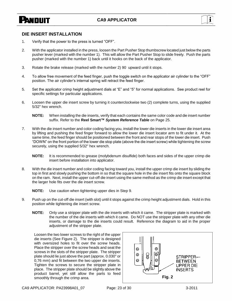
NOTE: Only use a stripper plate with the die inserts with which it came. The stripper plate is marked with the number of the die inserts with which it came. Do NOT use the stripper plate with any other die inserts, or damage to the die inserts could result. Reference the diagram to aid in the proper adjustment of the stripper plate.
Loosen the two lower screws to the right of the upper die inserts (See Figure 2). The stripper is designed with oversized holes to fit over the screw heads. Place the stripper over the screw heads and seat the screws in the slots of the stripper plate. The stripper plate should lie just above the part (approx. 0.030" or 0,76 mm) and fit between the two upper die inserts. Tighten the screws to secure the stripper plate in place. The stripper plate should be slightly above the product barrel, yet still allow the parts to feed smoothly through the crimp area.
Fig. 2

CA9 APPLICATOR
CA9 APPLICATOR: PA23998A01_07 Page: 24 of 30 3-2011
The stripper plate performs two functions, first it helps ensure the removal of the product from the dies after crimping, and second, it helps to prevent the product from rising too high off of the lower die before crimping (for presses without ―split cycle‖ function). If the wire processing machine does not have ―SHIFT‖ function capabilities (wire feed arm shifts right after termination to clear crimp area), the stripper plate may have to be raised slightly or removed completely to run certain types of male disconnects.
10. Proceed to Crimp Shut Height Tolerance Test on Page 26.
DIE INSERT CHANGEOVER
To change die inserts, remove upper inserts, stripper plate, and then lower inserts. Refer to Die Insert Installation section on Page 23, beginning with Step 1.
CA9 APPLICATOR
CA9 APPLICATOR: PA23998A01_07 Page: 25 of 30 3-2011
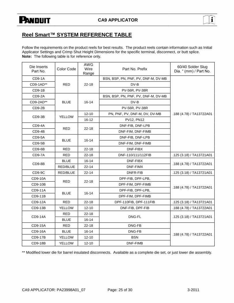
Reel Smart™ SYSTEM REFERENCE TABLE
Follow the requirements on the product reels for best results. The product reels contain information such as Initial Applicator Settings and Crimp Shut Height Dimensions for the specific terminal, disconnect, or butt splice.
Note: The following table is for reference only.
Die Inserts Part No.
Color Code AWG Wire
Range Part No. Prefix
60/40 Solder Slug Dia. ― (mm) / Part No.
CD9-1A
RED 22-18
BSN, BSP, PN, PNF, PV, DNF-M, DV-MB
.188 (4.78) / TA13722A01
CD9-1AD** DV-B
CD9-1B PV-56R, PV-38R
CD9-2A
BLUE 16-14
BSN, BSP, PN, PNF, PV, DNF-M, DV-MB
CD9-2AD** DV-B
CD9-2B PV-56R, PV-38R
CD9-3B YELLOW 12-10 PN, PNF, PV, DNF-M, DV, DV-MB
16-12 PV12, PN12
CD9-4A RED 22-18
DNF-FIB, DNF-LPB
CD9-4B DNF-FIM, DNF-FIMB
CD9-5A BLUE 16-14
DNF-FIB, DNF-LPB
CD9-5B DNF-FIM, DNF-FIMB
CD9-6B RED 22-18 DNF-FIBX
CD9-7A RED 22-18 DNF-110/111/112FIB .125 (3.18) / TA13721A01
CD9-8B BLUE 16-14 DNF-FIBX
.188 (4.78) / TA13722A01 RED/BLUE 22-14 DNF-FIMX
CD9-9C RED/BLUE 22-14 DNFR-FIB .125 (3.18) / TA13721A01
CD9-10A RED 22-18
DPF-FIB, DPF-LPB,
.188 (4.78) / TA13722A01 CD9-10B DPF-FIM, DPF-FIMB
CD9-11A BLUE 16-14
DPF-FIB, DPF-LPB,
CD9-11B DPF-FIM, DPF-FIMB
CD9-12A RED 22-18 DPF-110FIB, DPF-111FIB .125 (3.18) / TA13721A01
CD9-13B YELLOW 12-10 DNF-FIB, DPF-FIB .188 (4.78) / TA13722A01
CD9-14A RED 22-18
DNG-FL .125 (3.18) / TA13721A01 BLUE 16-14
CD9-15A RED 22-18 DNG-FB
.188 (4.78) / TA13722A01 CD9-16A BLUE 16-14 DNG-FB
CD9-17B YELLOW 12-10 BSN
CD9-18B YELLOW 12-10 DNF-FIMB
** Modified lower die for barrel insulated disconnects. Available as a complete die set, or just lower die assembly.
CA9 APPLICATOR
CA9 APPLICATOR: PA23998A01_07 Page: 26 of 30 3-2011
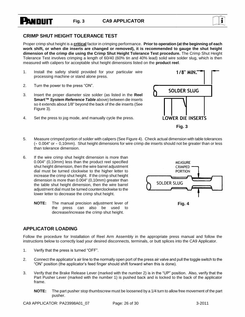
CRIMP SHUT HEIGHT TOLERANCE TEST
Proper crimp shut height is a critical factor in crimping performance. Prior to operation (at the beginning of each
work shift, or when die inserts are changed or removed), it is recommended to gauge the shut height
dimension of the crimp die using the Crimp Shut Height Tolerance Test procedure. The Crimp Shut Height Tolerance Test involves crimping a length of 60/40 (60% tin and 40% lead) solid wire solder slug, which is then
measured with calipers for acceptable shut height dimensions listed on the product reel. 1. Install the safety shield provided for your particular wire
processing machine or stand alone press. 2. Turn the power to the press ―ON‖.
3. Insert the proper diameter size solder (as listed in the Reel
Smart™ System Reference Table above) between die inserts so it extends about 1/8" beyond the back of the die inserts (See Figure 3).
4. Set the press to jog mode, and manually cycle the press.
Fig. 3
5. Measure crimped portion of solder with calipers (See Figure 4). Check actual dimension with table tolerances ( 0.004" or 0,10mm). Shut height dimensions for wire crimp die inserts should not be greater than or less
than tolerance dimension. 6. If the wire crimp shut height dimension is more than
0.004" (0,10mm) less than the product reel specified shut height dimension, then the wire barrel adjustment dial must be turned clockwise to the higher letter to increase the crimp shut height. If the crimp shut height dimension is more than 0.004" (0,10mm) greater than the table shut height dimension, then the wire barrel adjustment dial must be turned counterclockwise to the lower letter to decrease the crimp shut height.
NOTE: The manual precision adjustment lever of the press can also be used to decrease/increase the crimp shut height.
APPLICATOR LOADING
Follow the procedure for Installation of Reel Arm Assembly in the appropriate press manual and follow the instructions below to correctly load your desired disconnects, terminals, or butt splices into the CA9 Applicator. 1. Verify that the press is turned ―OFF‖. 2. Connect the applicator’s air line to the normally open port of the press air valve and pull the toggle switch to the
―ON‖ position (the applicator’s feed finger should shift forward when this is done). 3. Verify that the Brake Release Lever (marked with the number 2) is in the ―UP‖ position. Also, verify that the
Part Pusher Lever (marked with the number 1) is pushed back and is locked to the back of the applicator frame.
NOTE: The part pusher stop thumbscrew must be loosened by a 1/4 turn to allow free movement of the part
pusher.
Fig. 3
Fig. 4
CA9 APPLICATOR
CA9 APPLICATOR: PA23998A01_07 Page: 27 of 30 3-2011
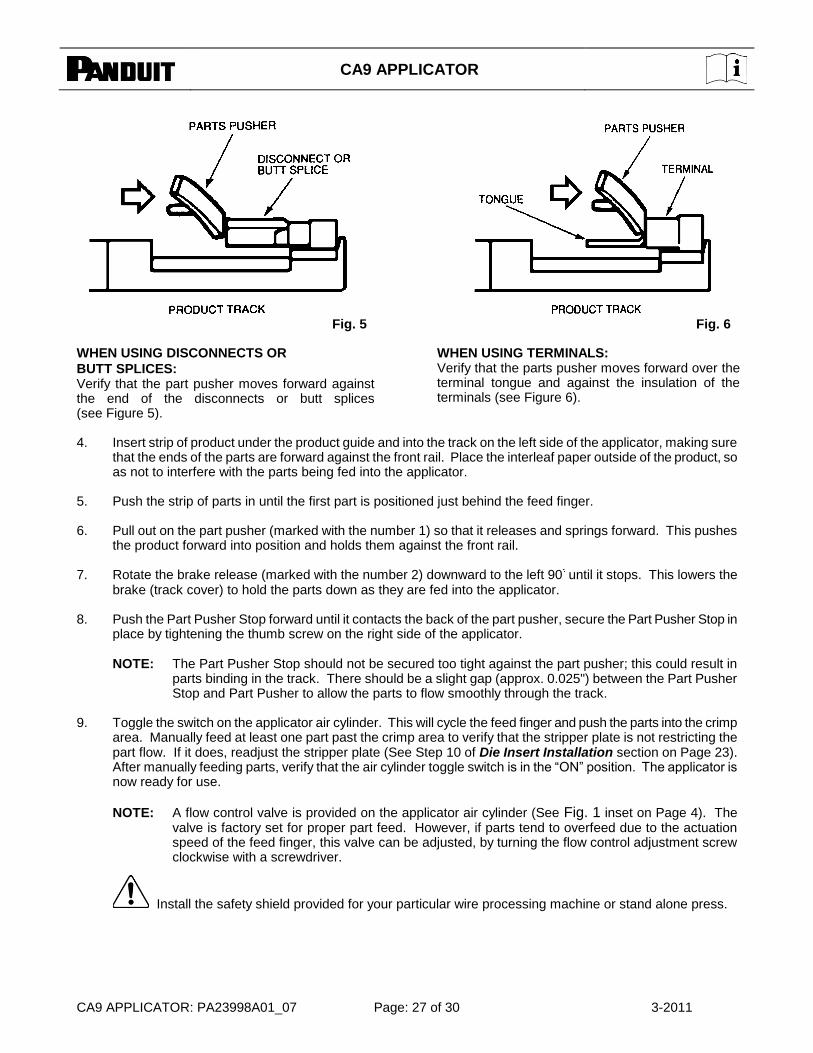
WHEN USING DISCONNECTS OR
BUTT SPLICES: Verify that the part pusher moves forward against the end of the disconnects or butt splices (see Figure 5).
WHEN USING TERMINALS: Verify that the parts pusher moves forward over the terminal tongue and against the insulation of the terminals (see Figure 6).
4. Insert strip of product under the product guide and into the track on the left side of the applicator, making sure
that the ends of the parts are forward against the front rail. Place the interleaf paper outside of the product, so as not to interfere with the parts being fed into the applicator.
5. Push the strip of parts in until the first part is positioned just behind the feed finger. 6. Pull out on the part pusher (marked with the number 1) so that it releases and springs forward. This pushes
the product forward into position and holds them against the front rail. 7. Rotate the brake release (marked with the number 2) downward to the left 90
until it stops. This lowers the
brake (track cover) to hold the parts down as they are fed into the applicator. 8. Push the Part Pusher Stop forward until it contacts the back of the part pusher, secure the Part Pusher Stop in
place by tightening the thumb screw on the right side of the applicator.
NOTE: The Part Pusher Stop should not be secured too tight against the part pusher; this could result in parts binding in the track. There should be a slight gap (approx. 0.025") between the Part Pusher Stop and Part Pusher to allow the parts to flow smoothly through the track.
9. Toggle the switch on the applicator air cylinder. This will cycle the feed finger and push the parts into the crimp
area. Manually feed at least one part past the crimp area to verify that the stripper plate is not restricting the part flow. If it does, readjust the stripper plate (See Step 10 of Die Insert Installation section on Page 23). After manually feeding parts, verify that the air cylinder toggle switch is in the ―ON‖ position. The applicator is now ready for use.
NOTE: A flow control valve is provided on the applicator air cylinder (See Fig. 1 inset on Page 4). The valve is factory set for proper part feed. However, if parts tend to overfeed due to the actuation speed of the feed finger, this valve can be adjusted, by turning the flow control adjustment screw clockwise with a screwdriver.
Install the safety shield provided for your particular wire processing machine or stand alone press.
Fig. 5 Fig. 6
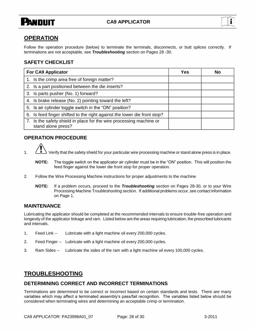
CA9 APPLICATOR
CA9 APPLICATOR: PA23998A01_07 Page: 28 of 30 3-2011
OPERATION
Follow the operation procedure (below) to terminate the terminals, disconnects, or butt splices correctly. If terminations are not acceptable, see Troubleshooting section on Pages 28 -30.
SAFETY CHECKLIST
For CA9 Applicator Yes No
1. Is the crimp area free of foreign matter?
2. Is a part positioned between the die inserts?
3. Is parts pusher (No. 1) forward?
4. Is brake release (No. 2) pointing toward the left?
5. Is air cylinder toggle switch in the ―ON‖ position?
6. Is feed finger shifted to the right against the lower die front stop?
7. Is the safety shield in place for the wire processing machine or stand alone press?
OPERATION PROCEDURE
1. Verify that the safety shield for your particular wire processing machine or stand alone press is in place.
NOTE: The toggle switch on the applicator air cylinder must be in the ―ON‖ position. This will position the feed finger against the lower die front stop for proper operation.
2. Follow the Wire Processing Machine instructions for proper adjustments to the machine
NOTE: If a problem occurs, proceed to the Troubleshooting section on Pages 28-30, or to your Wire Processing Machine Troubleshooting section. If additional problems occur, see contact information on Page 1.
MAINTENANCE
Lubricating the applicator should be completed at the recommended intervals to ensure trouble-free operation and longevity of the applicator linkage and ram. Listed below are the areas requiring lubrication, the prescribed lubricants and intervals. 1. Feed Link -- Lubricate with a light machine oil every 200,000 cycles.
2. Feed Finger -- Lubricate with a light machine oil every 200,000 cycles.
3. Ram Sides -- Lubricate the sides of the ram with a light machine oil every 100,000 cycles.
TROUBLESHOOTING
DETERMINING CORRECT AND INCORRECT TERMINATIONS
Terminations are determined to be correct or incorrect based on certain standards and tests. There are many variables which may affect a terminated assembly’s pass/fail recognition. The variables listed below should be considered when terminating wires and determining an acceptable crimp or termination.

CA9 APPLICATOR
CA9 APPLICATOR: PA23998A01_07 Page: 29 of 30 3-2011
1. Wire Size -- Is it relative to the product barrel size, crimp height and die inserts?
2. Barrel Size -- Is it relative to the wire size, crimp height and die inserts?
3. Die Inserts -- Are they correct for the specific product and wire size being terminated?
4. Crimp Shut Height -- Is it set at the suggested reading for the specific product/wire relation?
5. Strip Length -- Has the wire been stripped to the correct length per product reel specifications?
6. Turned Back Strands -- Have all the wire strands been inserted into the product?
7. Solid/Stranded Wire -- Has the testing been designed for both types of wires?
TROUBLESHOOTING CHECKLIST
PROBLEM CAUSE SOLUTION
System will not operate. A. Air hose not connected to air source.
B. Air cylinder toggle switch is turned ―OFF‖ (away from air cylinder).
A. Connect air hose to air source.
B. Turn air cylinder toggle switch ―ON‖ (toward air cylinder).
Parts will not feed into crimping area.
A. Parts pusher (No. 1) is not against parts properly.
B. Brake release (No. 2) is not pointing to the left.
C. Incorrect die inserts being used for the parts being terminated.
D. Air cylinder toggle switch is turned
―OFF‖ (away from air cylinder). E. Flow control valve on air cylinder is
fully closed (See Figure 1 inset on Page 3).
F. Air hose is connected to the wrong port of the press air valve.
G. Stripper plate is positioned too low, restricting part flow.
A. See Step 6 of the Applicator Loading section on Page 26.
B. See Step 7 of the Applicator Loading section on Page 26.
C. Check the Reel Smart™ System
Reference Table on Page 25 for the appropriate die inserts.
D. Turn the air cylinder toggle switch ―ON‖ (toward air cylinder).
E. With a small screwdriver, turn the flow
control set screw counterclockwise, 4 full rotations.
F. Connect the air hose to the normally open port of the press air valve.
G. Loosen and raise the stripper plate.
Parts are not being positioned correctly between die inserts--overfeed.
A. Brake release (No. 2) is not pointing to the left.
B. Incorrect die inserts being used for the parts being terminated.
C. Flow control valve on air cylinder is
fully open (See Figure 1 inset on Page 3).
D. Air pressure to CA9 Applicator is above 90 PSI.
A. See Step 7 of the Applicator Loading section on Page 26.
B. Check the Reel Smart™ System
Reference Table on Page 25 for the appropriate die inserts.
C. With a small screwdriver, turn the flow control set screw counterclockwise, until the proper feed is achieved.
D. Adjust air pressure to 80 – 90 PSI.
Parts are not being positioned correctly between die inserts--underfeed.
A. Excessive tension on parts reel. B. Incorrect die inserts being used for
the parts being terminated. C. Air pressure to CA9 Applicator is
below 80 PSI. D. Flow control valve on the air
cylinder is nearly fully closed (See Figure 1 inset on Page 3).
E. Lower die stop plate is not properly seated in base plate.
A. Check parts reel for binding.
B. Check the Reel Smart™ System
Reference Table on Page 25 for the appropriate die inserts.
C. Adjust air pressure to 80 – 90 PSI. D. With a small screwdriver, turn the flow
control set screw clockwise, until the proper feed is achieved.
E. Loosen the lower die screw. Push ―down‖ on the front portion of the lower die stop plate (above the die insert screw) while tightening the screw securely.
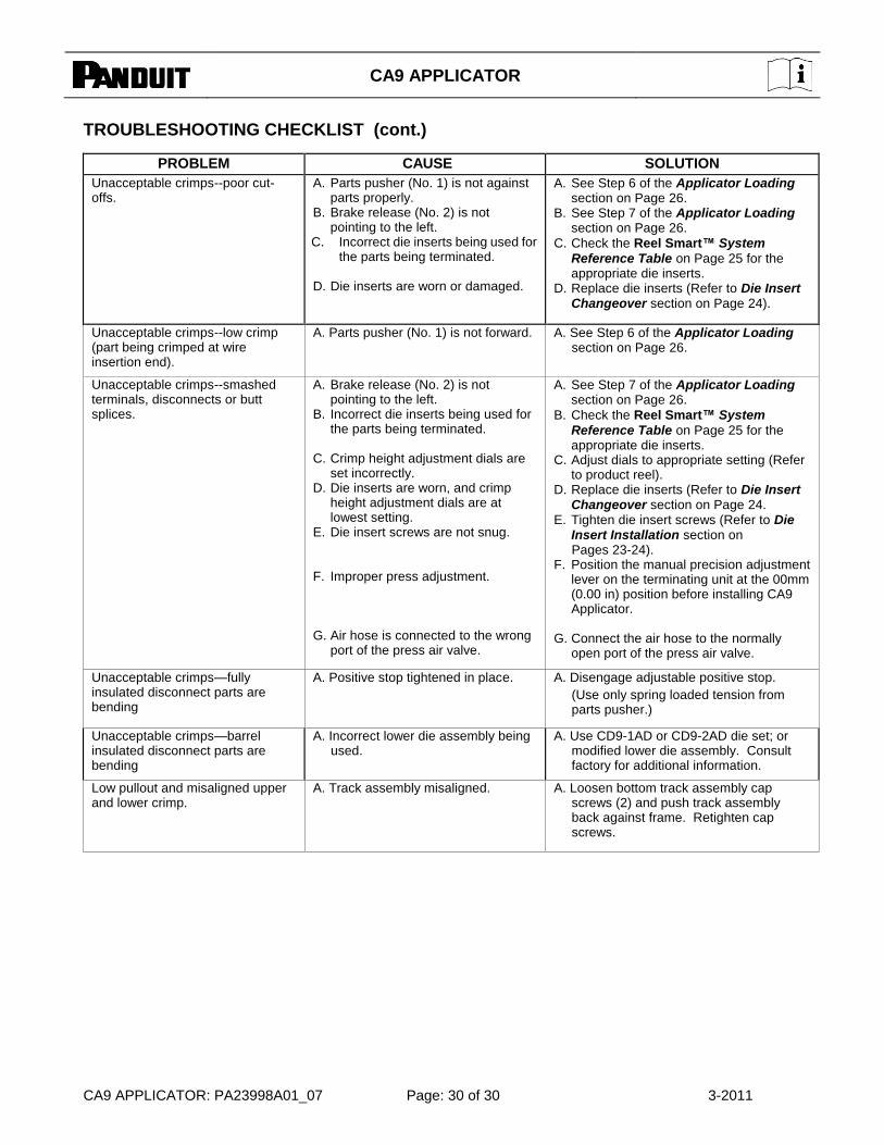
CA9 APPLICATOR
CA9 APPLICATOR: PA23998A01_07 Page: 30 of 30 3-2011
TROUBLESHOOTING CHECKLIST (cont.)
PROBLEM CAUSE SOLUTION
Unacceptable crimps--poor cut-offs.
A. Parts pusher (No. 1) is not against parts properly.
B. Brake release (No. 2) is not pointing to the left.
C. Incorrect die inserts being used for the parts being terminated.
D. Die inserts are worn or damaged.
A. See Step 6 of the Applicator Loading section on Page 26.
B. See Step 7 of the Applicator Loading section on Page 26.
C. Check the Reel Smart™ System
Reference Table on Page 25 for the appropriate die inserts.
D. Replace die inserts (Refer to Die Insert Changeover section on Page 24).
Unacceptable crimps--low crimp (part being crimped at wire insertion end).
A. Parts pusher (No. 1) is not forward. A. See Step 6 of the Applicator Loading section on Page 26.
Unacceptable crimps--smashed terminals, disconnects or butt splices.
A. Brake release (No. 2) is not pointing to the left.
B. Incorrect die inserts being used for the parts being terminated.
C. Crimp height adjustment dials are
set incorrectly. D. Die inserts are worn, and crimp
height adjustment dials are at lowest setting.
E. Die insert screws are not snug. F. Improper press adjustment. G. Air hose is connected to the wrong
port of the press air valve.
A. See Step 7 of the Applicator Loading section on Page 26.
B. Check the Reel Smart™ System
Reference Table on Page 25 for the appropriate die inserts.
C. Adjust dials to appropriate setting (Refer to product reel).
D. Replace die inserts (Refer to Die Insert Changeover section on Page 24.
E. Tighten die insert screws (Refer to Die Insert Installation section on Pages 23-24).
F. Position the manual precision adjustment lever on the terminating unit at the 00mm (0.00 in) position before installing CA9 Applicator.
G. Connect the air hose to the normally
open port of the press air valve.
Unacceptable crimps—fully insulated disconnect parts are bending
A. Positive stop tightened in place. A. Disengage adjustable positive stop.
(Use only spring loaded tension from parts pusher.)
Unacceptable crimps—barrel insulated disconnect parts are bending
A. Incorrect lower die assembly being used.
A. Use CD9-1AD or CD9-2AD die set; or modified lower die assembly. Consult factory for additional information.
Low pullout and misaligned upper and lower crimp.
A. Track assembly misaligned. A. Loosen bottom track assembly cap screws (2) and push track assembly back against frame. Retighten cap screws.