Embed Size (px)
Citation preview
Microlab® STAR User Manual
610766/02 Page 1 of 225
for User Software 3.0including Options and Accessories
HAMILTON Bonaduz AG

Microlab® STAR User Manual
Page 2 of 225 610766/02

Microlab® STAR User Manual
610766/02 Page 3 of 225
��������������
� ������������� ���������������������������������������������������������������������������������������������������������������
��� ���������� �� ���������������������������������������������������������������������������������������������������������������������� �
��� ������ ������� �������� �� �� �������������������������������������������������������������������������������������� �
��� ������������������������ ������ ��������������������������������������������������������������������������������������� �
��� ���� ��� �����������������������������������������������������������������������������������������������������������������������������������
��! � ���" ������������������������������������������������������������������������������������������������������������������������������������������
1.5.1 General Precautions........................................................................................................................... 8
1.5.2 Electrical Safety Precautions............................................................................................................. 9
1.5.3 Biohazard Precautions ....................................................................................................................... 9
1.5.4 Computer Precautions ....................................................................................................................... 9
��# $ �� ��"��� ��%��� ��������������������������������������������������������������������������������������������������������������� �&
��� '����%������(�� �������������������������������������������������������������������������������������������������������������������� ��
� ������ ������� ��� ������������������������������������������������������������������������������������������������������������
��� ������)��� ��%����*�����+�*������ ���������������������������������������������������������������������������� ��
��� ,��%����� �������)������+ ���������������������������������������������������������������������������������������������� ��
2.2.1 Tip Pick-up...................................................................................................................................... 13
2.2.2 Aspiration ........................................................................................................................................ 13
2.2.3 Dispense .......................................................................................................................................... 16
2.2.4 Tip Drop-Off ................................................................................................................................... 17
��� �(���+�'��� %� ������������������������������������������������������������������������������������������������������������ ��
��� -.���'� ����/�*�����+������/� ������� ������������������������������������������������������������������������� ��
2.4.1 Liquid Handling Examples.............................................................................................................. 18
��! *�������'������������������������������������������������������������������������������������������������������������������������������ �&
2.5.1 Monitored Air Displacement........................................................................................................... 20
2.5.2 Capacitance-Based Clot Detection .................................................................................................. 22
� ������� ������ ���������������� ������������������������������������������������������������������������������������
��� ����� �� �������� ����������������������������������������������������������������������������������������������������� ��
��� ������ ������������������������������������������������������������������������������������������������������������������������������������� ��
3.2.1 4, 8, 12 or 16 Pipetting Channels..................................................................................................... 24
3.2.2 High and Low Volume Channels .................................................................................................... 25
3.2.3 Autoload Option.............................................................................................................................. 26
��� ���������� ������������������������������������������������������������������������������������������������������������������������������� ��
3.3.1 Carriers ............................................................................................................................................ 27
3.3.2 Disposables...................................................................................................................................... 28
3.3.3 Needle Wash Station ....................................................................................................................... 28
3.3.4 Temperature-Controlled Carrier (TCC)........................................................................................... 31

Microlab® STAR User Manual
Page 4 of 225 610766/02
3.3.5 The Automated Vacuum System (AVS) ......................................................................................... 32
3.3.6 iSWAP............................................................................................................................................. 35
��� '�%��������.���%���� �������������������������������������������������������������������������������������������������������� �#
3.4.1 User Software .................................................................................................................................. 36
3.4.2 Firmware ......................................................................................................................................... 36
��! ���� �� ���� ������0�� ����������������������������������������������������������������������������������������������������������� �#
��# *�1���2�3��� +������������������������������������������������������������������������������������������������������������������������� ��
3.6.1 Basic Microlab STAR ..................................................................................................................... 37
3.6.2 Needle Wash Station ....................................................................................................................... 38
��� � ���� �������������������������������������������������������������������������������������������������������������������������������� �4
�� 3���� ��� ������������������������������������������������������������������������������������������������������������������������������ �4
��4 )���� � ������������������������������������������������������������������������������������������������������������������������������������ �4
���& �� ��+�������������������������������������������������������������������������������������������������������������������������������� �4
���� ����� �������� ���������������������������������������������������������������������������������������������������������� �&
3.11.1 Accuracy (Trueness and Precision) Specifications ..................................................................... 40
��������� ���!������ "������������������������������������������������������������������������������������������������ �
��� �(��(�1 ���������������������������������������������������������������������������������������������������������������������������������� ��
��� ������� ���)��5�- "���� ���������������������������������������������������������������������������������������������������� ��
4.2.1 “Save As”, or Saving Methods and Deck Layouts under Different Names .................................... 44
��� �������������������������1 �� ���������������������������������������������������������������������������������������������� ��
��� ��������+�� ��������������������������������������������������������������������������������������������������������������������������� �!
��! ,��������������������������������������������������������������������������������������������������������������������������������������� �#
# �� �$��� �%����$�� ��� ������������������������������������������������������������������������������������������������ �
& �������� ������'�(�)�$ ������������������������������������������������������������������������������������������������#*
#�� 6�1�)��5�- "��� �������������������������������������������������������������������������������������������������������������������� !�
6.1.1 Save Deck Layout ........................................................................................................................... 52
6.1.2 Open Existing Deck Layouts........................................................................................................... 52
#�� ����+�- �1 ���������)��5�- "��� ������������������������������������������������������������������������������������ !�
6.2.1 Adding Labware to Track Positions on the Deck............................................................................ 52
6.2.2 Adding Labware Directly to the Deck............................................................................................. 55
6.2.3 Teaching Labware ........................................................................................................................... 56
#�� � 5�+�' �+���������)��5�- "��� ������������������������������������������������������������������������������������ !
� ��+$�������������������������������������������������������������������������������������������������������������������������������#,
��� ��.������7���+ ��������������������������������������������������������������������������������������������������������������������� !4
7.1.1 Adding Positions to a Sequence ...................................................................................................... 60
7.1.2 Play.................................................................................................................................................. 61
7.1.3 Sorting Racks .................................................................................................................................. 61
7.1.4 Sorting by Grid Columns................................................................................................................. 61

Microlab® STAR User Manual
610766/02 Page 5 of 225
7.1.5 Sorting by Grid Rows...................................................................................................................... 62
7.1.6 Filter by Probe Head ....................................................................................................................... 62
7.1.7 Sorting Racks Example ................................................................................................................... 63
7.1.8 Sorting Grid Rows Example............................................................................................................ 65
- ������������ ��.�/.� �� �������������������������������������������������������������������������������������������������&&
�� 8���� ��������'�%% ��� �������������������������������������������������������������������������������������������������� #�
�� ���+������ ������0������������������������������������������������������������������������������������������������ #4
8.2.1 SMART Steps ................................................................................................................................. 70
8.2.2 Single Steps ..................................................................................................................................... 84
�� $���+� �������������������������������������������������������������������������������������������������������������������������� 4
�� 7���+� ��������������������������������������������������������������������������������������������������������������������������� 4
�! 3 � ���� ���������������������������������������������������������������������������������������������������������������������������������� 4&
�# ���+�-�� �"�,�������9�����-������-�� �" ��������������������������������������������������������������� 4�
�� :���+�������%����������������3 ����������������������������������������������������������������������������������� 4�
� $��5�+�1��$��5���� ��������������������������������������������������������������������������������������������������������� 4�
8.8.1 File Formats..................................................................................................................................... 93
8.8.2 Worklist Handling with Microsoft Excel ........................................................................................ 93
�4 $���+�: ��0�"�������������� ��#0' ���������� ���������������������������������������������� 4!
, 0�(��� ��.�/.� �� ����������������������������������������������������������������������������������������������������������,&
�* �$��%�� ��� ����������������������������������������������������������������������������������������������������������������������,-
�&�� ������-�5�+����������������������������������������������������������������������������������������������������������������� �&&
�� ������������������(�+$�.�/.� �� �������������������������������������������������������������������������������*�
���� '����������-.���'� ���� ������������������������������������������������������������������������������������������������ �&�
���� 7���+�-.���)�� ��������������������������������������������������������������������������������������������������������� �&�
���� )����+� �'����%�-.���'� �� �������������������������������������������������������������������������������������� �&�
���� �%�����+� ���7;�����+�-.��� ����������������������������������������������������������������������������������� �&!
�� ����������1��2��$ ��� �.�1��$$���)� �������������������������������������������������������������������*&
���� ����+� �����������3������������������������������������������������������������������������������������������������������� �&#
���� '�%% ������������3����������������������������������������������������������������������������������������������������� ���
���� * � �����*�������+�1������3� ������������������������������������������������������������������������������������ ���
�� �� ��.�������������������������������������������������������������������������������������������������������������
���� �(��(�1 ���������������������������������������������������������������������������������������������������������������������������� ���
���� '�� ��� ����������'��"����%�*� ������*� ������+������������ ���������������������������� ���
���� '�� ��� ����������'��"����%�*� ������*� ���1����+������������������������������������������� ���
���� '�� ��� ����������'��"����%����������*� �������+������������ ������������������������� ���
���! �����������*��������.��������+������������������������������������������������������������������� ��&
���# <'���"�*�5�+=/����>�1����' �+�� ���.������$��� ���������������������+������������ ��������������������������������������������������������������������������������������������������������� ���

Microlab® STAR User Manual
Page 6 of 225 610766/02
���� �����������+�������6������/���+��� ���������������������������������+�� %������������ �������������������������������������������������������������������������������������������� �!�
��� ��8���� ��7; %���������������0� ����������/�� %������ �5�+/�������������.������� ���� ���/����'������/� ����''���� ����������������������������������������������������� �!�
���4 ���+�����$�*���������� ��� ����� �������������������������������������������������������������������������� �#!
� (��.���� ���������������� �������������������������������������������������������������������������������������������&,
���� � �� ��-� ����������������������������������������������������������������������������������������������������������������������� �#4
�# �$������ ���������������� ��������������������������������������������������������������������������������������������
�!�� �����+� �� %����������1�����������%��������������������������������������������������������������� ���
�!�� �����%�� ���� ���������������������������������������������������������������������������������������������������������������� ��!
�!�� ����%��7�����> ����+�������������������������������������������������������������������������������������������������� ��#
�!�� $ �50�1 "�?*��������@�7�����> ����+ ���������������������������������������������������������������������� ��4
�& ����������������3����.��4����4�� �������������������������������������������������������������������������������-�
�� ����������$�.�5���������(��"��� ������������������������������������������������������������������������������-
���� ���- �1 ���7�������������������������������������������������������������������������������������������������������������� � �
���� �"�������� �1 �� ��������������������������������������������������������������������������������������������������������������� � �
17.2.1 Rectangular Racks and Plates ................................................................................................... 184
17.2.2 Containers ................................................................................................................................. 185
17.2.3 Circular Racks........................................................................................................................... 185
���� 7; %���9�)����+� ����� �+�� ��� �5�1��'��� ���� ��������������������������������������������� � !
17.3.1 Defining a Container................................................................................................................. 185
17.3.2 Defining a Rectangular Custom Rack....................................................................................... 188
17.3.3 Defining a Carrier (Template)................................................................................................... 193
���� �"���%�,� +������- �1 ���*�������� ����������������������������������������������������������������������������� �4
17.4.1 Structure.................................................................................................................................... 198
17.4.2 Information for Handling the Autoload Unit ........................................................................... 198
17.4.3 Information for Special Units.................................................................................................... 199
���! A�*����������' �����/�� �5�� ���'��� ���� �������������������������������������������������������������� �&�
�- ����������$�.�5�/6�������!����� ���0�(��� ��.�/.� �� �����������������������������������������*
� �� '�� ��� ����������'��"����%�*� ������*� ������������������������������������������������������������������� �&�
�����.������������������������������������������������������������������������������������������������������������������������������������*
�� 8���� �"���������������������������������������������������������������������������������������������������������������������������������� ��&
:� ����; ��������������������������������������������������������������������������������������������������������������������������������������� ��#
'� ��+�� ���"���� ������������������������������������������������������������������������������������������������������������������� ��4
)� ������+������% �������������������������������������������������������������������������������������������������������������� ���
7� *�����������' ��� ���������������������������������������������������������������������������������������������������������� ���
,� 6������$ ���� ���9�'�%� ��'�%� ����" ������������������������������������������������������������������ ���
Microlab® STAR User Manual
610766/02 Page 7 of 225
�� ������������������
Hamilton’s Microlab STAR is the next generation pipetting workstation. This User Manual isdesigned to help you get the most out of your Microlab STAR.
You should read through the entire manual before beginning to operate your instrument.This first chapter should be read with particular attention. It contains important informationabout the use of the Microlab STAR and this manual.
���� �����������������
This manual is to help users operate the Microlab STAR correctly and safely.
To achieve that aim, Chapter 3 of the manual will describe the different components of theMicrolab STAR and how they work. Then, in succeeding chapters, we will describe what canbe done with each – the basic operations of aspirating and dispensing liquids. The manualdescribes both the hardware and software of the Microlab STAR to the extent that a userneeds to know them in order to operate the instrument.
After introducing you to the various parts of the Microlab STAR, we show you step by stephow to perform typical operations using those components. Sample methods for typicalapplications guide you through the programming. When you have worked through thismanual, you should be quite well able to operate the Microlab STAR.
�������� and ��� are included in this manual to emphasize important and criticalinstructions. They are printed in italics in the left margin of the page, begin with the word'Attention' accompanied by the '!' symbol, or the word ‘Note’, as appropriate.
This manual refers to User Software release 3.0 for the Microlab STAR.
���� � ����������!���������"��������
A detailed software reference for the Microlab STAR is to be found in the online help of theUser Software. This online help will answer any question you may have about details of theMicrolab STAR User Software.
The manner in which the Microlab STAR and its components are to be serviced is describedin the ����� ������������������� . This manual will be made available to Hamilton-authorized service technicians.
Whenever a manual amendment is issued, detailed instructions on amending the existingmanual will be provided.
��#� ����� � �$������������!���������"
The Microlab STAR is a robotic pipetting workstation, in other words, a sampler used forpipetting liquid samples in an automated process suitable for medium to high throughput witha high degree of flexibility in pharmaceutical, veterinary and genetics applications.
A user will typically wish to carry out low, medium, or high volume contamination-freepipetting with disposable tips or with steel needles.
At the present time, the Microlab STAR is classified as a general laboratory instrument and isnot specifically validated as an ������� diagnostic device.

Microlab® STAR User Manual
Page 8 of 225 610766/02
��%� �&�������
The operator of the Microlab STAR must have attended an appropriate training course. Theprocedures contained within this manual have been tested by the manufacturer and aredeemed to be fully functional. Any departure from the procedures given here could lead toerroneous results or malfunction.
��'� �����(
The following section describes the main safety considerations, electrical and biological, inoperating this product, and the main hazards involved.
��'��� �������)��!�������
When using Microlab STAR, Good Laboratory Practices (GLP) should be observed. Suitableprotective clothing, safety glasses and protective gloves should be worn.
During Microlab STAR operation, do not place hands in the way of moving parts or on theworking deck. Keep your head and hands away from the work surface of the Microlab STARwhen it is in operation – the pipetting arm and channels move fast and it is possible tosustain an injury. In general, never lean over the Microlab STAR when working with it.
When working with samples, do not switch tubes around after they have been identified bythe barcode reader. This could result in incorrect test data.
When working with samples which will be used in particularly sensitive tests, take intoaccount evaporation and condensation that may occur while the method is running.
Perform test runs i) with deionized water and ii) with the final liquids, prior to routine use.Test for all the liquid classes you are going to use.
Liquid level detection needs to be explicitly tested when working with foaming liquids.
If sampling aggressive liquids, use filter tips.
During operation, the Microlab STAR should be shielded from direct sunlight and intenseartificial light.
���
������������������������������
����� �������������������������������������� ������������!����� �"�
#������������$���������������$���� �%���� � �������
��������� ����$�������� &��������������������� ����&��������� �&������������������������� ����������'����
(�����$�����������&�������������� ������������������������)������� �%������������ ������$���� �������� �������
����������� ��������������&����&�������� �%�������������
��������������������������� ������������������������
����� ������� ������������ �������� ������ � ����� �����$� ���������� �� ����������
�������������������������� $����������������$�������� ������������(�� �� ��������������������� &������������������������ $�
Microlab® STAR User Manual
610766/02 Page 9 of 225
*����������������������������������� � ��������$��������������$�������� ����������
�������������������������&���������������� ��$��������������������$����$�������������
#�������� ���$������$�������
������ ������������ ���������������������������� �� ���� �����������!��������������"���������$����������������* ������
For repair or shipment, all mechanical parts must be put in their rest positions. A MicrolabSTAR sent away for repair must also be decontaminated if it was in a laboratory environmentwith infected or hazardous materials. The Microlab STAR must be repacked in the originalshipping crate and only by an authorized service technician. There should be no containersor tips on the Microlab STAR during transportation.
Only original HAMILTON Microlab STAR-specific parts and tools may be used with theMicrolab STAR, e.g. carriers, racks, tips, steel needles, and waste containers. Commerciallyavailable liquid containers, such as microtiter plates and tubes, may of course be used.
If working with contaminated samples, the user need not touch them. The Microlab STAR willdrop its used tips into a waste container that should be emptied as soon as it is full.
The Microlab STAR products conform to European norms as regards interference immunity.However, if the Microlab STAR is subjected to electromagnetic RF fields, or if static electricityis discharged directly onto the Microlab STAR, its Liquid Level Detection ability (see below)may be negatively affected. It is therefore recommended that the Microlab STAR be keptaway from other equipment that emits electromagnetic RF fields in the laboratory, and thatstatic electricity be minimized in its immediate environment.
��'��� ���!���!��������(�)��!�������
Before removing a mechanical or electrical component, the Microlab STAR must first beswitched off and disconnected from the main electricity supply and PC.
��'�#� �����*�� �)��!�������
If the Microlab STAR becomes contaminated with biohazardous material, it should becleaned in accordance with the maintenance procedures given in the section “Maintenance”(3.7). Observe and carry out the maintenance procedures given. Failure to do so mayimpair the reliability and correct functioning of the Microlab STAR.
If working with biohazardous samples, observe and carry out the maintenance procedurespaying particular regard to cleaning and decontamination. Wear gloves when handling thepipetting arm and channels, the carriers, racks, and containers, and the tips and steelneedles. Avoid touching the discarded tips in the waste container. Any surfaces on whichliquid is spilled must be decontaminated.
��'�%� ��&�����)��!�������
Guard against software viruses. Use only manufacturer’s original installation CD-ROM setsfor the operating system, and the original HAMILTON software.
Only the HAMILTON User Software and the firmware protocol (CoCo/KuSt, cf�� ����� ������������������ ) may be used to control the Microlab STAR.

Microlab® STAR User Manual
Page 10 of 225 610766/02
��+� ,������(����������
HAMILTON Bonaduz AG, CH-7402 Bonaduz / Switzerland is the manufacturer of theMicrolab STAR.
The Microlab STAR is sold in accordance with the general conditions of sale of HAMILTONBonaduz AG.
HAMILTON warrants this product to be free of defects in material and workmanship for aperiod of 12 months from the date of delivery, ex works Bonaduz.
HAMILTON or the authorised HAMILTON representative will repair or replace, at its optionand free of charge, any product that under proper and normal use proves to be defectiveduring the warranty period.
HAMILTON shall in no event be liable or responsible for any incidental or consequentialdamage, either direct or contingent.
HAMILTON accessories and consumable products, e.g. carriers, racks, tips, steel needles,and waste containers, are warranted to be free of defects in material and workmanship at thetime of delivery only.
The above warranty shall not apply if:
• the product has not been operated in accordance with the user manual;
• the product is not regularly and correctly maintained;
• the product is not maintained, repaired or modified by a HAMILTON-authorizedrepresentative or user;
• parts other than original HAMILTON parts are used, except for liquid containers such asmicrotiter plates and tubes;
• the product or parts thereof have been altered without written authorization fromHAMILTON Bonaduz AG;
• the product is not returned properly packed in the original HAMILTON packaging.
HAMILTON reserves the right to refuse to accept any product that has been used withradioactive or microbiological substances, or any other material that may be deemedhazardous to employees of HAMILTON. Such a product has to be properly decontaminatedand marked.
HAMILTON endeavours to provide prompt and satisfactory service.
Microlab® STAR User Manual
610766/02 Page 11 of 225
��-� �����������.�!�
Customer service will be provided in the first instance by the network of HAMILTONrepresentatives. In the event of any problem experienced with your Microlab STAR, the firstrecourse is your local HAMILTON representative. For further problems requiring hardware orsoftware expertise, the Technical Support department at HAMILTON Bonaduz AG will beavailable by phone, fax or e-mail to deal with your queries. Here is their address, phone, faxand e-mail:
+����&�������&���������,
HAMILTON Bonaduz AGTechnical Support
P.O. Box 26CH-7402 Bonaduz / Switzerland
Phone +41 81 641 6060
Fax +41 81 641 6070
E-mail: itechsupport@ hamilton.ch
�������&�-���+��&�����.����������,
HAMILTON CompanyP.O. Box 10030
Reno, NV 89520-0012
USA
Toll Free: (800) 648-5950Phone (775) 858-3000Fax (775) 856-7259E-mail: [email protected]

Microlab® STAR User Manual
Page 12 of 225 610766/02
�� �����������)�&�����/
In this chapter the process of pipetting with the Microlab STAR is described. Pipetting meanstransfer of small quantities of liquid from one container to another. A pipetting operation isachieved by aspirating (drawing) liquid from a source container, then transferring anddispensing (dropping) it into a target container.
���� ��������0��&��!������)�&�����/�)���!�&��
The Microlab STAR is based on the ���� ��&��!������&�&�����/ principle, comparable to thefunctioning of hand pipettes. Air displacement means that the liquid is aspirated into anddispensed from a disposable tip or needle by the movement of a plunger. Between theplunger and the liquid surface is air. No system liquid of any kind is involved in the MicrolabSTAR.
����������� �����.������.������
The air displacement principle has the following advantages:
• Independent and modular design of pipetting heads for most flexible assay programming.
• CO-RE (compression-induced O-ring expansion) technology for the flexible coupling of
tips or needles to the pipetting channel.
• Tips or reusable needles of three sizes on the same head in the same run.
Microlab® STAR User Manual
610766/02 Page 13 of 225
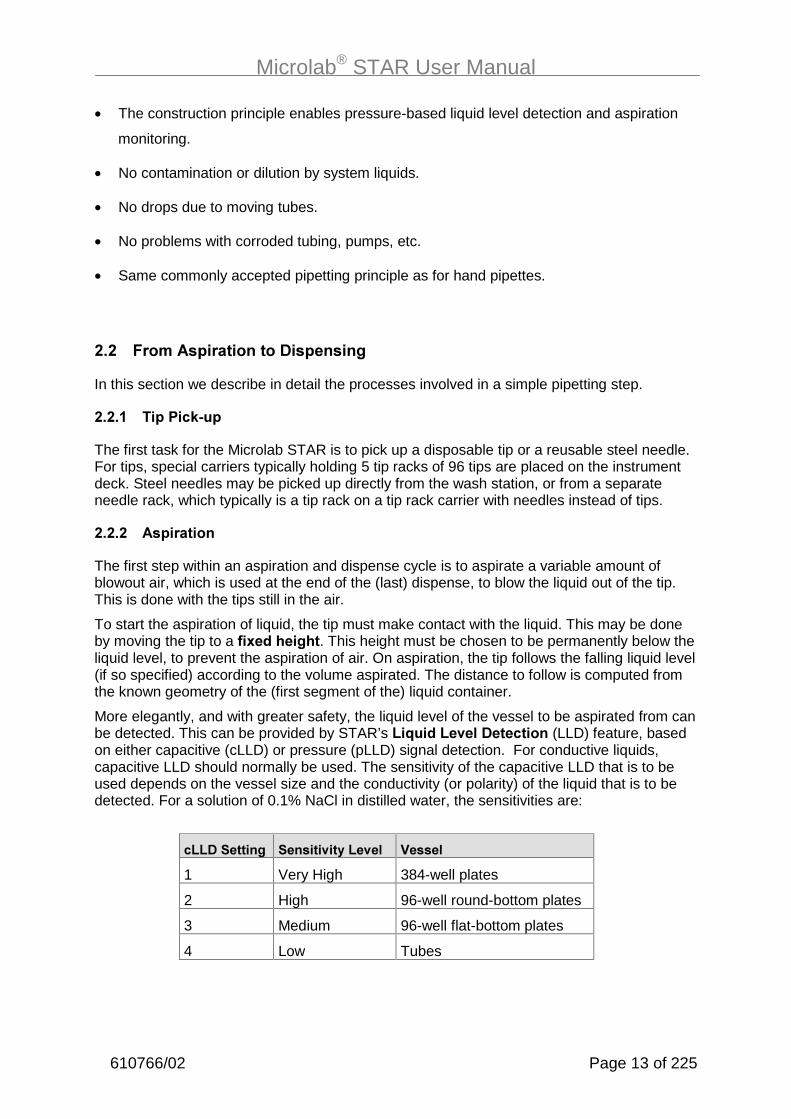
• The construction principle enables pressure-based liquid level detection and aspiration
monitoring.
• No contamination or dilution by system liquids.
• No drops due to moving tubes.
• No problems with corroded tubing, pumps, etc.
• Same commonly accepted pipetting principle as for hand pipettes.
���� �������&�����������0��&�����/
In this section we describe in detail the processes involved in a simple pipetting step.
������ ��&�)�!12�&
The first task for the Microlab STAR is to pick up a disposable tip or a reusable steel needle.For tips, special carriers typically holding 5 tip racks of 96 tips are placed on the instrumentdeck. Steel needles may be picked up directly from the wash station, or from a separateneedle rack, which typically is a tip rack on a tip rack carrier with needles instead of tips.
������ ��&�������
The first step within an aspiration and dispense cycle is to aspirate a variable amount ofblowout air, which is used at the end of the (last) dispense, to blow the liquid out of the tip.This is done with the tips still in the air.
To start the aspiration of liquid, the tip must make contact with the liquid. This may be doneby moving the tip to a ��3� ����/��. This height must be chosen to be permanently below theliquid level, to prevent the aspiration of air. On aspiration, the tip follows the falling liquid level(if so specified) according to the volume aspirated. The distance to follow is computed fromthe known geometry of the (first segment of the) liquid container.
More elegantly, and with greater safety, the liquid level of the vessel to be aspirated from canbe detected. This can be provided by STAR’s ��4�� ���.���0���!���� (LLD) feature, basedon either capacitive (cLLD) or pressure (pLLD) signal detection. For conductive liquids,capacitive LLD should normally be used. The sensitivity of the capacitive LLD that is to beused depends on the vessel size and the conductivity (or polarity) of the liquid that is to bedetected. For a solution of 0.1% NaCl in distilled water, the sensitivities are:
!��0�������/ �������.��(���.�� 5�����
1 Very High 384-well plates
2 High 96-well round-bottom plates
3 Medium 96-well flat-bottom plates
4 Low Tubes

Microlab® STAR User Manual
Page 14 of 225 610766/02
���
������������������������$��������$����� ���������� ��������$�� ����������� �%��� � ����������� ���
����� $�������� �/��� ��� ���������������-�������������������� �%���� � ������&������������������������ ������������������ ������!������������� ��"���������� �
For non-conductive liquids, or in case of an insufficient electrical coupling between containerbottom and carrier, pressure LLD should be used. Pressure LLD only works with new andempty tips for the aspiration of liquids. The suitable settings depend on the tip size and onthe type of liquid.
300 µl channel:
&��0�������/ �������.��(���.�� ��& ��4��
1 Very High Standard Low boiling point, low viscosity
2 High Low Low boiling point, low viscosity
3 Medium Standard Water or higher viscosity
4 Low Low Water or higher viscosity
1000 µl channel:
&��0�������/ �������.��(���.�� ��& ��4��
1 Very High Standard Low boiling point, low viscosity
2 High High Low boiling point, low viscosity
3 Medium Standard Water or higher viscosity
4 Low High Water or higher viscosity
In the case of ��&�������������������/���4�� �, capacitive liquid level detection in particularmay not detect the surface properly. As an alternative, try pressure LLD, or a combination ofboth. If you are using a combination of both LLD types, the maximum height differencebetween the two independent LLDs can be used as a parameter.

Microlab® STAR User Manual
610766/02 Page 15 of 225
The following table gives dead volumes for both pressure- and capacitance-based liquid leveldetection in various containers.
Labware Vmin/µl Carrier
Tubes, 16 mm x 100 mm 200 SMP-CAR-24
Tubes, 12 mm x 75 mm 150 SMP-CAR-32
Eppendorf tubes 1.5 ml 50 SMP-CAR-EPIL
Eppendorf tubes 0.5 ml 50 SMP-CAR-EPIS
96-well PCR plate (200µl/well) 50 PLT-CAR-L5PCR
96-well flat-bottom microplate 75 PLT-CAR-L5MD
384-well flat-bottom microplate 50 PLT-CAR-L5MD
96-deepwell microplate (archive) 150 PLT-CAR-L5AC
Once the liquid surface is detected, an additional immersion depth (typically 2mm) is reachedto prevent the aspiration of air, and���&������� starts. The tip follows the falling liquid level (ifso specified) according to the volume aspirated. Then, the tip leaves the liquid slowly andheads for the vessel to dispense into.
Finally, to prevent droplet formation, a variable amount of transport air is aspirated. After anaspiration step, the situation within the tip looks like this.
��������������������������������� ���������������
Tip
Blowout air (optional, mayreach into channel)
Liquid
Transport air (optional)
Channel

Microlab® STAR User Manual
Page 16 of 225 610766/02
����#� 0��&����
The transport air that was aspirated at the end of the aspiration step is first dispensed withthe tip still in the air. Dispensing of the liquid may now occur in two different modes: to theliquid surface or in a jet.
To ensure that the specified accuracy is achieved, volumes below 20 µl should always be ��&���� ��������4�� ������!�. For dispensing to a liquid surface use cLLD to detect theposition of the surface and then dispense by following the rising liquid level. For volumeslarger than 20 µl the liquid can be ��&���� ������6�� without touching the surface. Todispense in a jet specify a position a couple of millimeters above the surface and dispense byfollowing the rising liquid level. For dispensing in a jet, a varying amount of blowout air isused to make sure that all liquid is dispensed from the tip.
However, dispensing to the surface of an empty vessel (touch off) is also possible� Fordispensing into an empty container, position the tip less than 1 mm (typically 0.4 mm) abovethe bottom of the container and dispense, following the rising liquid level.
After the dispense, the situation within the tip looks like this:
�����������������,�-��� $&��������&� �%���&������ ������� ������������&��� �����$���������������������������� ���!���������������� ��� ����������"�����������������
Dispense in Jet Dispense to Surface
Tip
Blowout air (optional)
Liquid
Transport air as specifiedon aspiration(optional)
Channel
Transport air as specifiedon dispense (optional)
Stop back volume(optional)

Microlab® STAR User Manual
610766/02 Page 17 of 225
����%� ��&�0��&2���
The final step is to eject the used tip into the waste container of the Microlab STAR. A needlewill be placed back into the wash station, where the wash process may be started directly.
��#� �.�� ��/�������������
If cross-contamination is a concern, consider the following approaches:
• Use only HAMILTON tips�on the Microlab STAR.
• Use new tips for every pipetting step to avoid carry-over between different wells orcontainers.
• Use filter tips to avoid contamination of the pipetting channel by jets, aerosols, etc.
• Always dispense to a surface. Dispensing in a jet may produce aerosols and thus causecross-contamination.
• Always dispense using a residual volume, i.e., do not completely empty the tip ondispense. This can be achieved e.g. by aspirating 10 µl and dispensing only 9 µl.
��%� ��4�� �������7�)�&�����/��� ��7��� �����
In general, pipetting on the principle of air displacement (as with hand pipettes) is sensitive to
• the manner of pipetting (e.g. surface or jet),
• tip or needle type
• environmental effects (temperature, pressure, humidity), and
• liquid type.
The instrument’s behavior is determined by specifying the pipetting mode (e.g., surface or jetmode) and the liquid class. Pipetting mode and liquid class represent two independent setsof information which both have to be specified. For aspiration, three modes are possible:
• Simple “Aspiration”, for all standard cases,
• “Consecutive Aspiration” for aspiration with a tip that has already aspirated liquid, and
• “Aspirate All” for aspiration of all the liquid within a cup (specify a volume larger than whatis expected within the cup). In this case, aspiration monitoring is deactivated and the tipwill follow the falling liquid level (if specified) to the bottom of the container, staying therefor the rest of the aspiration.
For dispensing, four modes are possible:
• “Surface Dispense Part Volume” for dispensing only a part of the liquid in the tip to asurface, leaving a residual volume in the tip,
• “Surface Dispense Empty Tip” for dispensing all the liquid in the tip to a surface,
• “Jet Dispense Part Volume” for dispensing only a part of the liquid in the tip in a jet, i.e.without touching a surface, leaving a residual volume in the tip,
• “Jet Dispense Empty Tip” for dispensing all the liquid in the tip in a jet.

Microlab® STAR User Manual
Page 18 of 225 610766/02
The ��4�� �!���� stores all relevant background parameters, such as flow rates and volumecorrections, for one pipetting cycle, i.e. for one aspiration and the subsequent dispense(s).Depending on the pipetting mode chosen, only a subset of the parameters of the liquid classis active. According to the different dependencies listed above, liquid classes have attributesrelated to their intended use: tip type, liquid name, and dispense mode.
Different liquid classes are provided with the User Software and optimized for differentliquids, tip types, and important pipetting processes, such as aspiration followed bydispensing either to a surface or in a jet. HAMILTON has optimized the standard liquidclasses with great care to assure the best pipetting accuracy. To change HAMILTONstandard liquid classes, store the class under a different name first. For special applications,the user can define his or her own liquid class to achieve the highest accuracy with thecompounds and volumes of interest. For this purpose a Liquid Editor comes with theMicrolab STAR User Software. It is described in Chapter 11 below.
���
� ��$����������� �%����� ���������������������������������$� ��*������������ �������� ��� ������$��� ��������������������������� ����������������� ������$�������
��%��� ��4�� �8�� ���/��3��&���
Here are some examples of frequently-used combinations of liquid classes and pipettingmodes:
�����&������≥�9µ�������:����2��1����4�� 7� ��&�����'�µ������������&�(�;+2:����&����<�������� �� ���&�<�!���/����&���.��(�!(!��:
Liquid Class: StandardVolume_Water_DispenseJet
Aspiration Mode: Aspiration
Dispense Mode: Jet Dispense Empty Tip
Detection: Aspiration: LLD = pressure or capacitance or both, submerge to adepth of 2mm, following liquid level
Dispense: Fixed height of 5mm, not following liquid level
�����&��������:����2��1����4�� 7����/��� ��&������������&��2����� ��;+2:����&����<�������:.��������&�<�!���/����&���.��(�!(!��:
Liquid Class: LowVolume_Water_DispenseSurface
Aspiration Mode: Aspiration
Dispense Mode: Surface Dispense Empty Tip (in the liquid class selected here, theblowout volume is 0)
Detection: Aspiration: LLD = Pressure or Capacitance or both, Submerge Depth2mm, following liquid level
Dispense: Capacitance LLD on, following liquid level

Microlab® STAR User Manual
610766/02 Page 19 of 225
#����&������≥�9µ�������:����2��1����4�� 7� ��&�������������������������������&�(�;+2:����&����<�1��&���&�=
Liquid Class: StandardVolume_Water_DispenseJet
Aspiration Mode: Aspiration
Dispense Mode: Jet Dispense Empty Tip (empty tip only)
Detection: Aspiration: Capacitance LLD, submerge depth 2mm, following liquidlevel
Dispense: Fixed height of 5mm, not following liquid level
Comment: On first aspiration, pre-wetting of the tip by 1-3 mixing cycles isnecessary to equalize conditions for initial and subsequent dispenses.
%�����4�����/ of liquid means aspirating a given volume all at once and dispensing severalpartial volumes (aliquots) in a jet to different containers. In this frequently-used pipettingprocedure, measurements have revealed that the accuracy of the first and the last aliquot areoften not within the specified range. Therefore, to dispense e.g. 10 aliquots of 20 µl of a:����2��1����4�� with the ML-STAR, aspirate 240 µl and dispense 20 µl directly back into thecontainer. This is followed by dispensing 10 of the 20 µl aliquots. The last aliquot of 20 µl isdiscarded into another container or ejected with the tip. In addition, after the dispense ofevery aliquot, a given amount of air is aspirated and dispensed with the next aliquot.
Liquid Class: StandardVolumeWaterAliquotJet
Aspiration Mode: Aspiration
Dispense Mode: Jet Dispense part volume
Detection: Aspiration: Capacitance LLD, Submerge Depth 2mm, following liquidlevel
Dispense: Fixed height of 5mm, not following liquid level

Microlab® STAR User Manual
Page 20 of 225 610766/02
The following table gives sample values and results for pre- and post-aliquot volumes(please note that these are not technical specifications):
���2����(&�
��&�(&�
��4�� )��2:��
5�>?�@�������4�
��������4�
5�>?�@&��2���4�
5�>?�@&���2���4�
5A "A ����
300 Std Water Yes 20 12 20 20 1.5 -2.6 A
300 Std Water Yes 50 4 50 20 2.0 -1.1 A
300 Std Serum Yes 20 12 40 40 2.0 B
300 Std Serum Yes 50 4 70 50 4.5 B
1000 Std Water Yes 10 12 20 >10 3.9 -3.8 A
1000 Std Water Yes 20 12 20 20 2.5 -3.2 A
1000 Std Water Yes 50 4 50 20 2.0 -1.5 A
1000 High Water No 20 12 20 20 5 -1.6 C
1000 High Water No 50 12 50 50 2.5 -1.2 C
1000 High Water No 100 8 50 100 1.5 -0.9 C
1000 High Water No 200 4 50 100 1.5 -1.5 C
1000 High Serum Yes 100 8 100 100 1.0 -1.1 D
������������� �������$�����,����0��������1� �������!2334 "&�/���0/����1� ������!53334 "��.� �,�(��67�8&��� ������$�2 �� ����9��������������������������������� ��������$��1!������ �%�",�1� ������������ �%��&�1!�� � �%�",�1� ���������� �%��&�1!��� � �%�",�1� ����������� �%����:1,�.��������!��������������������&��������������������"&�,��������!�������������������"�����������:1��� ����������������$���� ��� ����������������: ���,�)�%����� �������������,8�������1� ��;���;� �%��<6&�=,�6�������1� ��;����;� �%��<6&�:,6/���1� ��;���;� �%��<6&��,�6/���1� ��;����;� �%��<6�������������������� ���������6<�������&�+��$����6�
��'� )��!����������
��'��� �������� �����0��&��!�����
The Microlab STAR is equipped with an aspiration monitoring feature. During the aspirationprocess, the pressure within the pipetting channel is measured in real time. Analyzing theshape of the p(t) curve, the system can distinguish the following situations:
- A correct aspiration takes place.
- Air is aspirated into the tip (because, for example, the cup has not been filled properly).
- A clot blocks the tip.
The aspiration monitoring can be switched on and off for each individual aspiration step of amethod using the appropriate commands (see section 2.4). For pressure-based clotdetection, a threshold can be given in arbritrary A/D (analog/digital) values (typically 100 A/D
Microlab® STAR User Manual
610766/02 Page 21 of 225
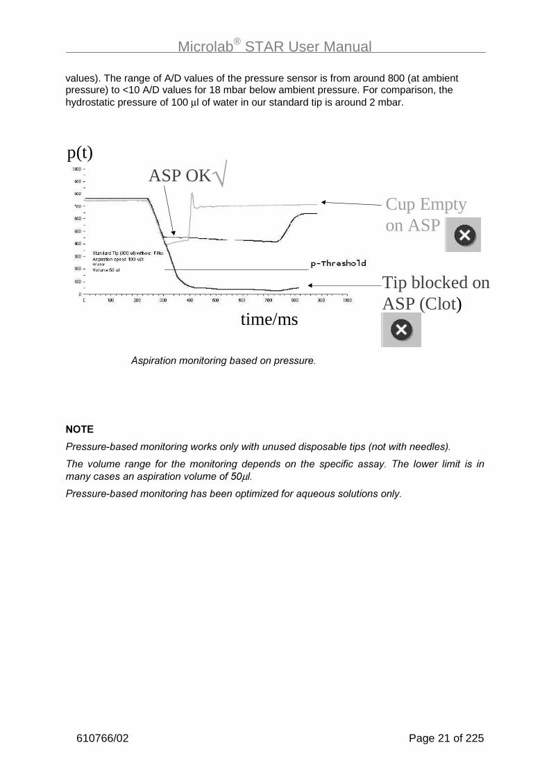
values). The range of A/D values of the pressure sensor is from around 800 (at ambientpressure) to <10 A/D values for 18 mbar below ambient pressure. For comparison, thehydrostatic pressure of 100 µl of water in our standard tip is around 2 mbar.
�����������������������������������
���
.����� ����������������������� $������������������� �����!��������� �"�
��� �� ��� ����� ���� ������������ ������ ��� �� �������� ����$�� ��� ���� ���� ��� �����$��������������������� ������>3µ �
.����� ���������������������������?�������%������� �������� $�
Cup Emptyon ASP
ASP OK
Tip blocked onASP (Clot)
p(t)
time/ms
√

Microlab® STAR User Manual
Page 22 of 225 610766/02
��'��� �&�!����!�2���� �����0���!����
In addition to pressure-based clot detection, the ML STAR is equipped with capacitance-based clot detection, too. This detection approach works for an aspiration with capacitanceliquid level detection switched on. The system measures the conductive signal when the tipleaves the liquid after aspiration. Due to the air gap between tip and liquid, the capacitancesignal will vanish once a given height is reached (the “clot retract height”, which is specifiedwithin the liquid class). If a clot is present, it bridges the distance and the signal will remain,resulting in an error message. A typical clot retract height is 2-5 mm. This is illustrated below.
This clot detection is independent of pressure-based monitoring.
Clot Retract Height

Microlab® STAR User Manual
610766/02 Page 23 of 225
#� 0��!��&��������������!���������"
#��� �������� �� ���!���������"
STAR stands for Sequential Transfer and Aliquoting Robot. The Microlab STAR performspipetting operations on liquids in containers placed on its work surface.
The basic model Microlab STAR contains a work surface, called a deck, for placing movablecarriers. These carriers hold reagent containers, such as tubes, microtiter plates, or otherkinds of labware.
��������� �������
The Microlab STAR’s deck is divided into 54 equal tracks (T) for loading carriers withpredetermined positions. This obviates the need for precise measurement of positions. Thedeck has partitions for a maximum of 54 specialised 1-T carriers for sample tubes, or amaximum of 9 6-T carriers for microtiter plates and CO-RE tips. An additional partition spaceis provided for the tip waste container.
Carrier for tubes,microtiter plates,etc.
WasteContainer
PipettingArm
PipettingChannel/PipettingHead
Front Shieldand Window
z
x
y
(0,0,0)AutoloadUnit
LoadingTray
Deck
Microlab® STAR User Manual
Page 24 of 225 610766/02
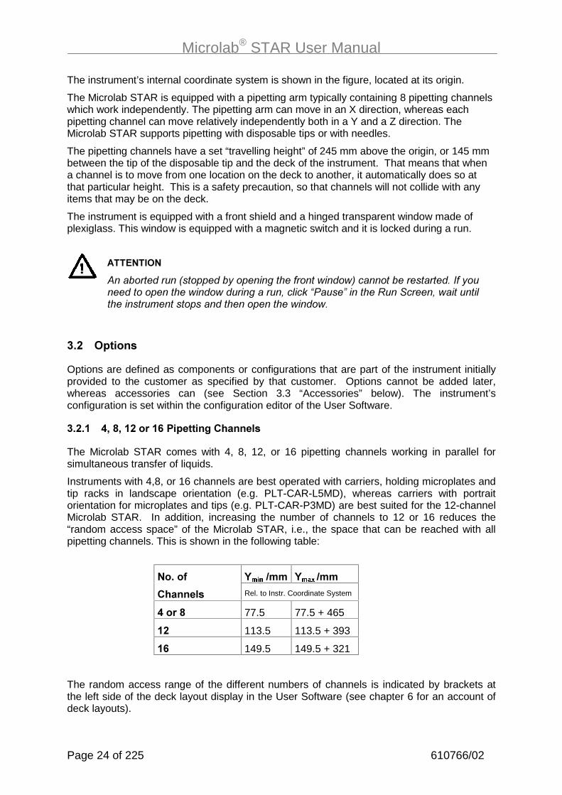
The instrument’s internal coordinate system is shown in the figure, located at its origin.
The Microlab STAR is equipped with a pipetting arm typically containing 8 pipetting channelswhich work independently. The pipetting arm can move in an X direction, whereas eachpipetting channel can move relatively independently both in a Y and a Z direction. TheMicrolab STAR supports pipetting with disposable tips or with needles.
The pipetting channels have a set “travelling height” of 245 mm above the origin, or 145 mmbetween the tip of the disposable tip and the deck of the instrument. That means that whena channel is to move from one location on the deck to another, it automatically does so atthat particular height. This is a safety precaution, so that channels will not collide with anyitems that may be on the deck.
The instrument is equipped with a front shield and a hinged transparent window made ofplexiglass. This window is equipped with a magnetic switch and it is locked during a run.
�������
�������������!�������$���������������������"����������������(��$��������������������������������&�� ����6.���8��������������&�������� �����������������������������������
#��� �&�����
Options are defined as components or configurations that are part of the instrument initiallyprovided to the customer as specified by that customer. Options cannot be added later,whereas accessories can (see Section 3.3 “Accessories” below). The instrument’sconfiguration is set within the configuration editor of the User Software.
#����� %7�B7��������+�)�&�����/��������
The Microlab STAR comes with 4, 8, 12, or 16 pipetting channels working in parallel forsimultaneous transfer of liquids.
Instruments with 4,8, or 16 channels are best operated with carriers, holding microplates andtip racks in landscape orientation (e.g. PLT-CAR-L5MD), whereas carriers with portraitorientation for microplates and tips (e.g. PLT-CAR-P3MD) are best suited for the 12-channelMicrolab STAR. In addition, increasing the number of channels to 12 or 16 reduces the“random access space” of the Microlab STAR, i.e., the space that can be reached with allpipetting channels. This is shown in the following table:
C����D�� C����D�������
������� Rel. to Instr. Coordinate System
%����B 77.5 77.5 + 465
�� 113.5 113.5 + 393
�+ 149.5 149.5 + 321
The random access range of the different numbers of channels is indicated by brackets atthe left side of the deck layout display in the User Software (see chapter 6 for an account ofdeck layouts).

Microlab® STAR User Manual
610766/02 Page 25 of 225
To guarantee random access to sample carriers, only the inner tube positions should beused. The number of blank positions to be used for the different instrument configurations islisted in the following table:
��)2�"2#� ��)2�"2�% ��)2�"2��������������
���������1�
"�������1�
���������1�
"�������1�
���������1�
"�������1�
4 or 8 0 0 0 0 0 0
12 3 3 2 2 1 1
16 5 5 4 4 2 2
The 16-channel Microlab STAR is intended as a batch-type processor, i.e., random access toall positions is not possible. By contrast with an 8-channel Microlab STAR, the methods for a16-channel instrument should be set up in such a way that all positions are processed inbatches of at least 8 (or better 16, to optimize the pipetting speed) with 8 (or 16)simultaneous aspirations or dispenses at identical x-coordinates (see section 8.9 for more).
���
(���������������������������������������������������������������&����$����$��������/����&������� $����� $������������� ������������� ���
#����� 8�/���� ���:�5�������������
Different pipetting heads are available for the different volume ranges:
a) from less than 1 µl to 300 µl (for the use of low volume tips = 10 µl, and standard tips= 300 µl), or
b) from 5 µl to 1000 µl (for the use of standard tips = 300 µl, and high volume tips =1000 µl).
Currently, a mixing of high and low volume channels on one and the same instrument is notfeasible.
Microlab® STAR User Manual
Page 26 of 225 610766/02
#���#� ������� ��&����
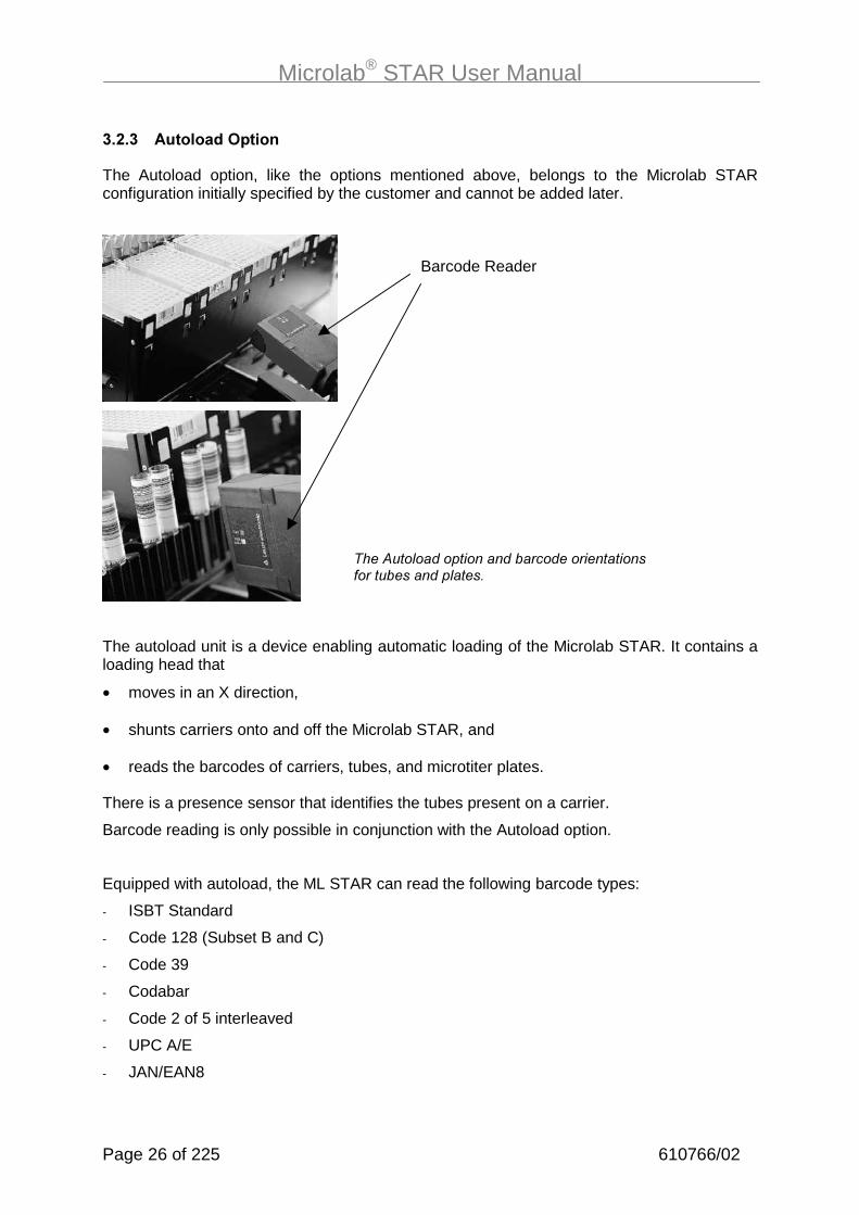
The Autoload option, like the options mentioned above, belongs to the Microlab STARconfiguration initially specified by the customer and cannot be added later.
The autoload unit is a device enabling automatic loading of the Microlab STAR. It contains aloading head that
• moves in an X direction,
• shunts carriers onto and off the Microlab STAR, and
• reads the barcodes of carriers, tubes, and microtiter plates.
There is a presence sensor that identifies the tubes present on a carrier.
Barcode reading is only possible in conjunction with the Autoload option.
Equipped with autoload, the ML STAR can read the following barcode types:
- ISBT Standard
- Code 128 (Subset B and C)
- Code 39
- Codabar
- Code 2 of 5 interleaved
- UPC A/E
- JAN/EAN8
Barcode Reader
������ ������������������������������������������� ���

Microlab® STAR User Manual
610766/02 Page 27 of 225
���
(���������&��������������������������������� �$�!���&������������&���?&����������������������������������"������� $��������� �
+������������������������������������������ ���!����������������������"�
#�#� �!!��������
Accessories are defined as additional components that can be ordered later by the customerand installed either by HAMILTON personnel, or by the customer. They include carriers, awash station, a temperature-controlled carrier and an automatic vacuum system, which aredescribed in this section of the manual. Note that the availability of accessories is subject tochange. Please ask for a current list.
�������� ������������:������&�����������&�������� ����� ��:�����&����1�������$���
#�#��� �������
The labware is placed on special carriers which are loaded onto the Microlab STAR.HAMILTON provides a wide range of standard carriers for microtiter plates, tubes, tips etc.All standard carriers can be added to the deck by the user.
The naming of carriers follows a systematic nomenclature: E2C2F2���.
E: stands for the type of labware, placed on the carriers, e.g., TIP (= tips),
PLT (plates), SMP (=samples)
C=CAR for carrier
Wash Station
Pump Stationwith 3 washsolutions andwaste container
Heat Exchangerfor TCC
Controller forVacuum Box

Microlab® STAR User Manual
Page 28 of 225 610766/02
F: describes the labware details, e.g.,
�: landscape orientation
): portrait orientation
�����: number of items placed on the carrier (plates or tips)
�0: medium density (96- or 384-well microplates)
80: high density microplates (1536)
�: 96-well archive plates
��� identifies the part number revision (e.g. A00)
�3��&��=� PLT-CAR-L5MD-A00 is a carrier for 5 medium density (96- or 384-well)microplates in landscape orientation.
A carrier must always be identified (e.g in deck layouts and methods) by the uniquedescriptor with which it is tagged.
#�#��� 0��&�������
CO-RE tips come in 3 sizes: low-volume, standard, and high-volume (approximately 10, 300,and 1000 µl respectively). One blister pack contains 5 racks of 96 tips, giving a total of 480tips. CO-RE tips are available in boxes of 4000-6000, depending on the tip size. CO-RE tipsare produced under sterile conditions, i.e. the tips are RNAse- and DNAse-free.
Reusable needles with 50, 300, and 1000 µl volumes may be used instead of tips. OnlyHAMILTON needles and disposable tips should be used for coupling to the pipetting channelof the Microlab STAR.
#�#�#� �� ���,�����������
The needle wash station is a device for the washing and drying of steel needles parallel tothe pipetting process. The wash station has the width of a normal microplate carrier (6T) andis mounted on the deck of the Microlab STAR. All tubing and electrical connections arerouted through the docking station at the rear of the instrument. Along with each wash stationcomes a pump station with three reservoir containers for wash solutions and a wastecontainer. This pump station is placed below the bench on which the Microlab STAR rests.
/��()�*#�� ��� ������������� �����������) ����

Microlab® STAR User Manual
610766/02 Page 29 of 225
The principle of the wash station is illustrated in the following figure, where a typicalprocedure is shown.
�������� �������� ��� �� � ����� ������,� #� �� ��� � ���� ���� �� �������� &����������������������� ����������������5"����������@"�������� �������������������� ��� ������������������ ����9� ���$������� � �%�����������
One wash station consists of three individual 8-fold wash modules ���� ���� ����� ��� ���(&�: High Volume (1000 µl), Standard Volume (300 µl), or Low Volume (50 µl).
To enable parallel pipetting with an 8-channel Microlab STAR, the following cycle of stepstakes place:
1. fresh needles are picked up from the first module for pipetting, used, and then placedback into the same module. Washing starts.
2. fresh needles are picked up from the second module for pipetting, used, and then placedback into the same module. Washing starts.
3. fresh needles are picked up from the third module for pipetting, used, and then placedback into the same module. Washing starts.
4. The next set of needles is picked up from the first module again, which in the meantimehas washed and dried all 8 needles. The process is repeated again.
The needle wash station needs to be installed by a trained Hamilton engineer.
���
����������������� ����������������������
������������������ �$��&��������������������������$���������
-��� �� 5A ����� � �������&� ��� �������� ����� ������� ��� ������$� �� ��� �������������������������� �$��
����9��������@�������������!��������2���������� �����������������������"���������� ������������� ��������
The carry-over of the wash station depends on the wash program. Typical values are 10-5 to10-6.
The wash parameters can be set within the User Software, prior to each wash step.
�� 5�2�)� ��� 5

Microlab® STAR User Manual
Page 30 of 225 610766/02
For each of the two wash solutions (or wash and rinse solution), a set of parameters can bespecified:
- The G����������H�is the length of time liquid flows through the wash chamber.
- The G���1�����H is the length of time wash liquid is held within the wash chamber.
- The G���:�����H is given in millilitres per second for both wash liquids.
For the drying of needles an additional parameter is used:
- The G ������/� ����H gives the length of time allotted for draining the liquid from theneedles.
A set of default parameters is given for the wash process within the relevant dialog boxes ofthe User Software.
To empty the waste liquid container or to refill the wash solutions, lift the container by thehandle. The valve at the bottom automatically closes, sealing the container. To reattach thecontainer, simply slot it back into its original position.
��� �%������������������������������������������������ �������� �������� ��������������������� ������5@�)�
Customers can order one of two complete variants of the wash station: “regular“, suitable formost uses, and “chemical-resistant“, specially designed to meet the needs of those workingwith aggressive chemicals. Each variant is complete with 3 wash modules and pump station.For each variant there are high-, standard- and low-volume options. The part numbers forthe various options are given in the table below:
Regular Chemical-Resistant
Low Vol. 182575 182722
Std. Vol. 182574 182721
High Vol. 182573 182720
���
���� ���������� ��������� ������������������������������������������9�-��������������� ��������������� �������$����������������� ���������� ������������������� ����� $�
Wash Solution One: red,2 right-most containers (2 x 3 L)
Wash Solution Two: blue,left-hand container (1 x 3 L)

Microlab® STAR User Manual
610766/02 Page 31 of 225
:����� �������������������� $���������������� ������������� �%������� ���������� ��� ���� �������������� ���������������������� �%����������������9���$&������������&�����������&���
�������
����� ��������������������� ��������������9� ����� ����������������������� ����� ����9� ������ ��������������&���������$��������������������
#�#�%� ���&�������2�������� ��������I�J
The temperature-controlled carrier is a device to heat and cool microplates. The TCC hasfour positions for microplates, which are all of the same temperature. The TCC may heatmicroplates up to 60°C, or cool them down to 22°C below ambient temperature. The TCC isable to read barcodes on the microplates (with the autoload option). It consist of a platecarrier with peltier elements on the instrument deck and a service station with a heatexchanger below the bench. For the heat exchanger, a water-based heat exchange liquid isused in a closed cycle; it is stored in a reservoir.
Typical times (at 40% rel. humidity) to heat and cool the TCC are (Tambient = 20°C):
Tambient to 60°C 20 mins
60°C to Tambient 20 mins
Tambient to 4°C 15 mins
4°C to 60°C 25 mins
��������� ����� ���������!�::"�

Microlab® STAR User Manual
Page 32 of 225 610766/02
������9��������� �������������
���
+������������ ��$�������� �%����!5�)"�����������������
� �������9������������9���������������������
������� ���������������::����������������������#��� ������::��� ������������ ������$�
�� ��������9��������� ���������$�� $�
��������������������� �������::���������� ������������
� ��$�������������::������������������������������� ��������������
The TCC will be installed by a trained Hamilton service engineer. A maximum of 2 TCCs canbe placed on one Microlab STAR.
#�#�'� ������������ �5�!�����(�����I�5�J

Microlab® STAR User Manual
610766/02 Page 33 of 225
The Automated Vacuum Box System consists of a vacuum box, a vacuum controller and thecontrolling software. The Vacuum Box is fitted to the deck of the Microlab STAR and iscontrolled by the workstation‘s computer. For this integration, a special deck has to bemounted on the Microlab STAR. The vacuum box accommodates a wide variety of 96-wellfilter and collection plates and is automated, so that the filter plate can be transported from awaste/conditioning chamber to an elution chamber. The vacuum box is compact and amaximum of two can be used in parallel on the Microlab STAR deck with the same controller.Filter plates can be placed onto or removed from the system by hand or with the help of arobotic arm (see the section on iSWAP below).
The vacuum controller allows for user-defined vacuum settings. The software integratesseamlessly with MICROLAB Vector. Loading is handled with a step in the method.
We now turn to a description of the components of the automated vacuum box system.
����������
The picture on the left provides a bird’s-eye view of the vacuum box, showing theconditioning chamber on the right and the elution chamber on the left, which is covered inthis picture by the carriage. A lid gasket in the carriage provides the sealing surface for thefilter plate and a chamber gasket provides the sealing surface for the carriage. In the pictureon the right, the carriage is on the way to the elution chamber.
The picture above shows the ports on the vacuum box. There are three ports into which isfed the tubing that goes to the vacuum box controller. There is also a push-button switch thatallows the user to manually operate the carriage. An electronic control port is used for powerand communication.

Microlab® STAR User Manual
Page 34 of 225 610766/02
�������������� ������
One Controller can control up to two vacuum boxes. The front of the controller has eightports. Six of these are needed for conditioning, elution and waste removal. There is also avacuum exhaust port for venting vapors and a “waste out“ port for draining liquid from theconditioning chamber.
Pictured above is the right side of the controller with the different connections. Thecommunication with the computer is via a USB cable. As the controller requires 24 volts, apower supply with 24 volts is delivered together with the controller.
Vacuum Box 1Vacuum Box 2
24 Volt Power Connection
Connection to theVacuum Box 1
Connection to theWaste Box
USB Connection to theComputer

Microlab® STAR User Manual
610766/02 Page 35 of 225
��� ����� ����
The waste is collected in the closed-systemwaste container with liquid level monitoringto prevent overflows.The waste container with a volume of 10 litresshould preferably be placed below the levelof the instrument. The waste level sensorhas to be connected with the controller.
The AVS and its components are to be installed by a Hamilton service engineer.
#�#�+� ��,�)
The iSWAP (internal Swivel Arm Plate Handler) transports microplates, covers ofmicroplates, archive plates or filter plates used for the vacuum box to and frompositions on the deck of the Microlab STAR IVD. The plates can be placed inlandscape or portrait orientation and rotated 180 degrees. In addition, the iSWAP isable to load and unload plates to and from a plate stacker on the left side of theinstrument outside the working area (with some restrictions, this can also be done onthe right side). Like Microlab STAR’s pipetting channels, iSWAP has a “travellingheight” of 145 mm above the deck (245 mm above the origin).
The iSWAP is mounted on the pipetting arm and parked below the cover of thepipetting arm. In this position it does not affect the movement of the pipettingchannels.
�����.������������
iSWAP can be chosen by the customer as an ordering option, but can also be installed laterby a service technician at the customer’s request.

Microlab® STAR User Manual
Page 36 of 225 610766/02
#�%� ��&�����"�4���������
The Microlab STAR is controlled by a dedicated user software program which controls allfunctions for daily work routine, method programming, running methods, and other services.
The Microlab STAR and the computer controlling it may be linked in two different ways:
- By a serial interface (RS232), or
- By a Unified Serial Bus interface (USB).
The Microlab STAR automatically recognizes the type of communication in use.
The Microlab STAR requires a recent model of PC including a mouse, CD-ROM drive, highresolution monitor and graphics (SVGA or better), 1-2 serial ports for a USB, about 1 GBHDD and ≥128 MB RAM, and Windows 2000 (service pack 1 or better) as the operatingsystem.
To avoid any loss of data, we recommend a UPS (uninterruptable power supply) for the PC.
���
����� �������B�����������������������������������������@333�9� ���� $���������������� ���������������$��������������$��� ������������@333���$� ��� ��������� ��������� ��������
#�%��� $��������:���
The Microlab STAR User Software is the controlling software for the Microlab STAR.
It is a WindowsTM-based, menu-driven interface allowing the user to define deck layouts andmethods, and then to run the Microlab STAR.
The Microlab STAR User Software allows the user to program and run different methods foraspirating and dispensing liquids.
���+����������������������������� ������$�������
#�%��� ����:���
Firmware is the set of instructions that are downloaded to the Microlab STAR by themanufacturer to enable the instrument to carry out its functions. Normally, the User Softwareis used to control the instrument. However, the Microlab STAR can be controlled directly withthe CoCo firmware protocol (CoCo means ’Communication and Control’). This is done bycontrolling actions of the Microlab STAR with single firmware commands. Firmwarecommands are listed in the ����������� for the use of Hamilton engineers servicing theinstrument.
#�'� ��������������� ����2$&
The Microlab STAR will be unpacked and installed and initial set-up performed by a trainedHAMILTON technician. The customer need only ensure that a suitable control PC isavailable for installation of the ML STAR User Software.
Make sure that the Microlab STAR is connected to a 115 to 230 V AC (50 or 60 Hz) socket.The Microlab STAR automatically recognizes any voltage within that range, without userintervention. Select the appropriate voltage at the pump station of the needle washer. Theneedle washer does not recognize the voltage automatically.

Microlab® STAR User Manual
610766/02 Page 37 of 225
#�+� )�:���D�5����/�
#�+��� ����!���!���������"
We recommend using a Uninterruptible Power Supply (UPS) for the Microlab STAR.
Ensure that the instrument is correctly earthed when connected to the power supply.
The mains plug is on the left hand side of the instrument towards the rear (see picture 1below).
The fuses for the instrument are situated in the mains power switch (see picture 2 below).
Plug the mains cables for the computer and the instrument into the same electrical outlet.Connect them only to an earthed outlet.
.�����5 .�����@
�������
� ��$����������������� ���� ������@@3 @C3�1∼. �������������������������������������������������������������������
The technical specifications regarding electrical power are listed in the following table.
Maximum power consumption:
Voltage:
Frequency:
Delayed action fuse:
115 V∼:
230 V∼:
600W
115 / 230 V∼ -15 % + 15 %
50 / 60 Hz ± 5 %
6.3 A
3.15 A
Overvoltage category II
Degree of pollution 2
Fuses
Voltage selector
Always at 220 – 240 V

Microlab® STAR User Manual
Page 38 of 225 610766/02
#�+��� �� ���,�����������
The needle wash station has its own power supply. The mains plug is on the rear of thepump station (see picture below).
Ensure that the the needle wash station is correctly earthed when connected to the powersupply. Connect the wash station only to an earthed outlet.
Ensure that the voltage selector is correctly set before operating the needle wash station.
The fuses for the instrument are situated next to the mains power switch (see picture below).The pump station has two fuses for the power supply which can be accessed by opening thecover above the mains plug.
� -����������������� $�������� �����.
The technical specifications regarding electrical power for the wash station are listed in thefollowing table:
Maximum power consumption:
Voltage:
Frequency:
Delayed action fuse:
115 V∼:
230 V∼:
140 W
115 / 230 V∼ -15 % + 15 %
50 / 60 Hz ± 5 %
3.15 A (T3.15L250)
1.6 A (T1.6L250)
Overvoltage category II
Degree of pollution 2
Voltage Selector
Fuses for powersupply

Microlab® STAR User Manual
610766/02 Page 39 of 225
#�-� ���������!�
A short preventive maintenance including volume verification should be carried out twiceyearly. Typically, the service and volume verification are carried out by a trained HAMILTONservice engineer.
To clean the instrument deck use the procedures required by GLP. To preserve plasticmaterials from damage, do not use organic solvents.
If a spray is used, do not point the spray directly at the autoload unit or at electrical boards orconnectors.
#�B� 5�����!�����
The Microlab STAR will be verified by a trained HAMILTON technician upon initial set-up,and thereafter at regular intervals for a period of time specified by service agreements.HAMILTON recommends that this verification take place four times yearly.
For volume verification in the field, HAMILTON will supply a verification tool, based ongravimetrical measurements (the “gold standard” of volume verification). The detailedspecifications are listed in the specification table at the end of this chapter.
Conditions are valid only for the HAMILTON verification kit.
#�;� 0��&����
After the life cycle of the instrument has terminated, the Microlab STAR may be shipped tothe original manufacturer or retailer. Otherwise local disposal regulations are to be observed.
#��9� �������/
Training in operation of the Microlab STAR and the User Software will be provided byHAMILTON personnel upon initial set-up.

Microlab® STAR User Manual
Page 40 of 225 610766/02
#���� ��!���!����&�!���!������
#������ �!!���!(�I����������� �)��!�����J��&�!���!������
The pipetting specifications for the Microlab STAR are given in the following table. Thedifferences in the specifications are due to the accuracy of the gravimetrical measurement,which to a great extent depends on the quality of the balance, as well as on the stability ofthe environmental conditions (pressure, humidity, temperature).
#99�µ��I��:�5�����J�)�&�����/�������
0���/���&�!� ������������/��&�!� ���� �5�����!������&�!�
5���Dµ� 5��Dµ� K"KDA 5DA K"KDA 5DA K"KDA 5DA
200 300 1 0.75 1.5 1 2 1.5
50 300 2 0.75 2.5 1 - -
10 300 5 2 6 2.5 - -
5 10 2.5 1.5 3 2 6 5
2 10 5 3.5 6 4 - -
1 10 5.0 6 - - - -
�999�µ��I8�/��5�����J�)�&�����/�������
0���/���&�!� ������������/��&�!� ���� �5�����!������&�!�
5���Dµ� 5��Dµ� K"KDA 5DA K"KDA 5DA K"KDA 5DA
1000 1000 1 0.75 1.5 1 2.0 1.5
500 1000 1.5 0.75 2 1 - -
200 300 1 0.75 1.5 1 - -
100 300 1.5 0.75 2 1 - -
50 300 2 0.75 2.5 1 - -
10 300 5 2 6 2.5 9 6
1��������1��� ������� ������� �%����������&������� $���������������������������������������������������������������������������������� ���������-��� ������������������������ ���������������������������������&������������������������������������������� �������D������ �������������������� �� ����������������������9�+&�E.������ �����:� �������8�
Microlab® STAR User Manual
610766/02 Page 41 of 225
The design specifications mentioned above are valid under the following conditions, obtainedfor measurements at HAMILTON Bonaduz:
• Test method: Gravimetric testing at Hamilton. The scatter of the test method mustbe less than 1/6 of the specified precision (for one channel).
• Trueness/Precision The values given refer to use of 8 pipetting channels.
• Test size: ≥ 12 single pipettings per channel with disposable CO-RE tips (pick-up and dispense, tip used only once) per channel and specifiedvolume
• Test mode: Volumes ≥ 20µl as jet dispense, < 20µl as (liquid) surface dispense
• Acceptance criteria: Measured values are within specifications if less than the valuesappearing in the table on p. 40.
• Test temperature: 20 ± 2°C
• Test fluid Deionized water with 0.1 % NaCl, 0.01% Tween
���
#��������$��������������������������������������������������������������������$����� �%����������������������������������
*���� ������������������ ���������������������� ����������������������� ������������������������>F�
���������������������������������� ����������������5>���2>G�:&�������� ���������$����23� �D>F�������������������

Microlab® STAR User Manual
Page 42 of 225 610766/02
%� 0���/���������$��������:���
%��� �.��.��:
The Microlab STAR User Software is the controlling software for the Microlab STAR.
It is a WindowsTM-based, menu-driven interface allowing the user to define deck layouts andmethods, and then to run the Microlab STAR.
The Microlab STAR User Software allows the user to program and run different methods foraspirating and dispensing liquids. Note that each programmed method has to be validated bythe user. The deck layout is defined within the Deck Layout Editor, whereas the aspirationand dispense steps are defined using the method editor. An independent run control is usedto run the methods programmed.
For ease of use, there are two different options for programming. In both cases, a “master” orcentral editor is selected, which can either be the method or the deck layout editor. Whatevereditor is started first is the master editor. All other (“slave”) editors and the run control arethen called from the master editor, using easy access shortcut buttons. If you make changeswithin one of the slave editors, the master editor is automatically updated once you quit theslave editor. This is illustrated below with the deck editor as master:
Deck Editor is Master Method Editor is Slave
Run Control is Slave
Labware Editor: Auxiliary
Sequence Editor: Auxiliary

Microlab® STAR User Manual
610766/02 Page 43 of 225
Alternatively, the user may start with the method editor as the master editor (if there is noshortcut to the method editor, create it manually. The relevant executable file is...\hamilton\bin\HxMethEd.exe):
The auxiliary modules and tools (small arrows in the above figures) are called from the toolmenu by menu items or tool icons. Finally, the method is executed using the independent runcontrol. In some cases, one may wish to define special labware items or sequences(pipetting patterns - see below) using the labware editor and the sequence editor.
%��� ����� ���� �0�!1���(����
The Microlab STAR User Software allows an �,� relation between deck layouts andmethods. This means that one deck layout may be used for different methods or one methoduses different deck layouts, e.g., to link two Microlab STARs, or a Microlab STAR and aMicrolab SWAP.
The run control allows you to start either deck layouts (with the corresponding method ifthere is only one), or, in general, methods. These methods are then either executed orsimulated.
Method Editor isMaster Deck Editor is Slave
Run Control is Slave
Labware Editor:Auxiliary
Sequence Editor:Auxiliary

Microlab® STAR User Manual
Page 44 of 225 610766/02
%����� G��.����H7������.��/������ ���� �0�!1���(������� ���0�������������
Due to the �,� relation between deck layouts and methods, the “Save as” option needs to beused in the following way:
To save a method under a different name, still referring to the old deck layout:
• Select “Save As” in the method editor and save the old method A under a new name B.The new method B is still linked to the old deck layout A.
To save a method and the corresponding deck layout under a new name:
• Start the Method Editor as the (first opened) master editor.
• Select “Save As” to save method A under the new name method B.
• Start the Deck Editor to save deck layout A under the new name deck layout B. Close theDeck Layout Editor.
• Link method B to deck layout B (Methods->Instruments). Save method B.
%�#� ����!������������$��������:���
The User Software consists of a set of modules and tools (programs) which work together.These modules and tools are grouped into a general (instrument-independent) and a specific(instrument-dependent) group. Given that structure, a system with different HAMILTONinstruments (even non-HAMILTON instruments, suitably adapted) can be controlled andoperated in the same manner, in the same environment and at the same time. The generalmodules get all the specific information they need about instruments (such as pipetting steps,or information about the probe head) from the instrument-dependent modules.
The general modules with a common “look and feel” for all HAMILTON instruments include:
• Deck layout editor (for mapping the position of labware on the deck)
• Method editor (for programming methods)
• Sequence editor (for defining pipetting sequences)
• Labware editor (for defining custom labware to be used in deck layouts)
• HSL Method editor (for programming methods using text entry mode)
• Run execution (for running methods on the instrument).
The general tools include:
• Version info.
The Microlab STAR-specific editors include:
• Liquid Editor (for defining liquid classes)
• Configuration Editor (for configuring the User Software to a particular instrument)
The Graphical Method Editor lets the user write methods in a graphical, syntax-freeenvironment. Technically, this editor is a code generator producing a low-level code which isthen interpreted by the run control. This low level code is called HSL (Hamilton StandardLanguage), because it provides a common programming approach for all Hamiltoninstruments. HSL can be accessed directly using the HSL Method Editor. HSL is a syntax-dependent language that offers even more flexibility than the Graphical Method Editor. Theinstrument-specific steps (e.g. aspiration, dispense - see below) are the same for the

Microlab® STAR User Manual
610766/02 Page 45 of 225
graphical and the HSL method editor. The general syntax used in the HSL is the C/C++notation and associated language constructs.
%�%� �!!����"�/���
The User Software does not define any user access restrictions. However, specific accessrights may be restricted to trained users within the operating system, or by applying write-protection to specific files.

Microlab® STAR User Manual
Page 46 of 225 610766/02
%�'� ���������!����
The installation generates the following default directory structure, if not requested otherwise.
Note in particular the file contents of the following directories:
���: Executables, DLLs
����/: Configuration Files
���:���: Labware Definitions
��/�����: Com Traces (Port Trace), Tip Counter File (TipCount.xls)
����� �: Methods (*.med, *.hsl), Deck Layouts (*.lay), Method Traces (*.trc)
������(: HSL libraries of commonly-used additional functions
!=L���!� ���In addition, this directory is used by the sample tracker to store Microlab AT-likebarcode and register files.

Microlab® STAR User Manual
610766/02 Page 47 of 225
'� ���������������/�������
As described in Chapter 3, the Microlab STAR is available in several variants. To configurethe User Software to a specific instrument configuration, the Configuration Editor is availablewithin the Deck Layout Editor under Tools->Configuration:
The first decision to be made - prior to a run - is whether to run the method with theinstrument or to simulate the run without using the instrument. Run simulation is a tool to testwhether a method has been programmed correctly. The run simulator creates a methodtrace file with pipetting pattern and other useful information.
Click the Advanced button to access the instrument configuration screen. Different tabs arevisible:
������(�������������������
Select your instrument configuration. Waste16 (as in picture above) is the correct sequenceof the waste container for disposable tips. Teaching mode refers to the possibility of“teaching” positions on the instrument deck, which can be done moving the arm by the

Microlab® STAR User Manual
Page 48 of 225 610766/02
keyboard or by a teaching box (accessory). The channel to be used for “teaching” is to bespecified, too.
The next tab refers to barcode handling:
The different barcodes which are allowed on the instrument can be selected here. Inaddition, the generation of a barcode trace file (barcodes_N.txt) can be switched on and off,storing rack barcode and track position on deck as well as tube (or plate) barcodes andpositions within the rack. The sample tracker, which generates a database of liquid transfersin the background can be switched on here, too. This sample tracker is used to generate aMicrolab AT-like barcode file using a special filter tool.
The error settings tab allows you to specify the step width in mm for blood clot error recovery(the channels move up on request by the step width). The return string separators are usedto define the syntax of single step return values.
The step selection finally allows you to exclude steps such as the move commands from themethod editor.

Microlab® STAR User Manual
610766/02 Page 49 of 225
Only if “instrument” is selected within the configuration editor is the additional tab“communication settings” visible.
Select the type of communication and the com port for communication via RS232 interface.
Click “save” to activate the new settings or “abort” to leave the settings unchanged.

Microlab® STAR User Manual
Page 50 of 225 610766/02
+� 0������/�����0�!1���(���
In the Hamilton Deck Layout Editor, the user is prompted to tell the system which labware(carriers, racks, or containers) is to be used in the procedure, and where these items areplaced on the deck. This is called “defining a deck layout”.
The 'Hamilton Deck Layout Editor is started by double-clicking the shortcut icon displayed onthe desktop of your PC.
���� �$�������
The method editor and the run screen can be started from the deck layout editor by clickingthe appropriate buttons located in the leftmost frame.
For access to the main modules, a toolbar is provided. In that toolbar the following choicesare available (some of which are deactivated):
• New deck layout
• Open deck layout
• Save deck layout
• Method editor
• Run execution
• Labware editor
• Sequence editor
• Zoom in deck layout
• Zoom out deck layout

Microlab® STAR User Manual
610766/02 Page 51 of 225
+��� �:�0�!1���(���
Under the File menu or in the toolbar, select New to start the definition of a new deck layout.
If multiple instruments are installed on your PC, a dialog window will appear. Select aninstrument (e.g. ‘ML_STAR’ for Microlab STAR) and click OK. If there is only one instrumentinstalled, the template (base definition of a deck layout) of that instrument is shown directly.
� ��(�������������
The deck layout displayed below shows the tracks of the predefined grids from theappropriate deck template.
+9��� ,��������������������� �����������
Use the (+) zoom button to enlarge the deck view.
A deck template is an instrument-specific definition of dimensions, main grid and hiddengrids, with preloaded standard labware such as a waste container. Deck templates can becustomized.

Microlab® STAR User Manual
Page 52 of 225 610766/02
+����� ��.��0�!1���(���
The complete loading of the deck may be stored under a chosen file name (extension: “.lay”),e.g. “MyDemo.lay”. This is done using the Save, Save As... commands in the File menu.
After a deck layout has been defined and saved, you are ready to start programming yourmethod.
+����� �&����3�����/�0�!1���(����
It is possible to load previously defined deck layouts (extension “.lay”) by selecting “Open”under the File menu.
+��� � ��/����:�����������0�!1���(���
Basically, the deck is freely configurable. The term labware refers here to carriers (availablefrom Hamilton) as well as microplates (from various manufacturers) and tip racks. Thegeneral procedure is first to add a carrier for a special kind of plate to the deck and then addthe plate to the carrier. There is a restriction, however, that carriers �������$����������� ��� $ are available as standard parts. Therefore, do not place a deep-well microplate and aflat microplate (for example) on the same set of vertical positions in the deck layout.
�������
(������������������ �������� $���H��������� ��������������&������� ����� ���������$ ��������� ����������������� �����������������������������������
+����� � ��/����:����������!1�)����������������0�!1
The software comes with a set of ready-made labware definitions for the standard labwareitems that are most commonly used in laboratories. The carrier name and definition selectedmust always be identical to the name with which the physical carrier is labelled.
Here are some frequently used Hamilton standard carriers:
- Plate carriers for 5 flat 96- or 384-well microplates PLT-CAR-L5MD
- Plate carriers for 4 1536-well microplates PLT-CAR-L4HD
- Plate carriers for 5 96-deepwell (or archive) microplates PLT-CAR-L5AC
- Tip carriers for 5 tip racks of 96 tips each TIP-CAR-480
- Preloaded carriers for 32 or 24 tubes with defined diameter and lengthCAR24_Cup15x75
- Plate carriers for 5 96-well PCR microplates PLT-CAR-L5PCR
- Plate carriers for 3 96- or 384-well flat microplates in portrait orientation PLT-CAR-L3MD
- Plate carriers for 3 96-deepwell microplates in portrait orientation PLT-CAR-L3AC
- Carrier for 12 reagent containers of 100 ml each REA-CAR-L3AT
- Temperature-controlled carrier No 1 and No 2 CAR_TCC_1, CAR_TCC_2
- Wash Station No 1 and No 2 for needles: CAR_Wash_1_LowNeedle, etc.

Microlab® STAR User Manual
610766/02 Page 53 of 225
Carrier definitions are stored under ...\hamilton\labware\ML_star. Files defining carriertemplates have the extension *.tml. A carrier features a varying number of locations for theplacement of labware, such as tip racks, microplates, etc.
To add a carrier to the deck layout, simply double-click on the appropriate track position. The“add labware” dialog box opens up. Type in a name for the carrier and click browse to selectthe PLT_CAR_L5MD from the \labware\ML_star directory. Click OK in the “add labware”dialog.
The carrier is now added to the deck layout.
The next step is to add a plate to this carrier. The corresponding labware (plates, tip racks,etc.) is sorted by manufacturer and stored within the Labware directory. Standard plates fromalmost every major manufacturer are available:
- Nunc
- Falcon
- Greiner, etc.

Microlab® STAR User Manual
Page 54 of 225 610766/02
Microplates, tip racks, etc. are labware items and generally called “racks”. The defining fileshave the extension “.rck”
To add a plate to the carrier, double-click on the desired carrier position. Again, the “addlabware” dialog box opens. Select the Nun_96_Fl_L.rck (96-well flat-bottom Nunc plate inlandscape orientation) from the labware\nunc directory. Give a name to the plate, e.g.,“MyPlate”.
The plate is added to the site. Plates (or labware) may be moved between sites on onecarrier by simple drag-and-drop.
Besides plate and tip carriers, tube carriers can also be placed on the deck. These carriersare preloaded with tubes of a defined size (diameter and length). In fact, these carriers areracks (*.rck) in contrast to the other carriers, which are carrier templates (*.tml). The tubecarriers are an example of racks which fit directly into the track grid of the Microlab STAR.

Microlab® STAR User Manual
610766/02 Page 55 of 225
+����� � ��/����:����0���!��(��������0�!1
To place labware (e.g. microplates) directly onto the deck (without using a carrier), select“Add Labware” from the Edit Menu. A dialog window opens up: Select the type of labwarefrom the library and enter the x,y,z coordinates by hand.
You may enter a name by which the rack will be known on the deck.
In the type field, select the already listed labware item or press Browse to load anotherlabware item to the list. Click OK. If the labware position falls outside the instrument deck, amessage window opens to inform you.
Use the 'Rotate' button to rotate the labware item in increments of 90 degrees and type theposition in X,Y, and Z coordinates into the input boxes under Deck Position. Click OK.
If the labware item is to be placed at an angle other than 90, 180, 270 or 360 degrees, the'Free form' mode will have to be used. Here, two sets of coordinates are required.

Microlab® STAR User Manual
Page 56 of 225 610766/02
+���#� ���!���/����:���
“Teaching” means guiding a channel or other probe to a particular location on the deck andassigning a name to that location. The User Software enables you to record the x-y-zcoordinates of that point and to associate them with the name you have given the location.Afterwards, you need only specify the name of the location and ML-STAR “remembers”exactly where it is on the deck. The precise position of labware items can be “taught” in thisway, using the needle from the teaching station. This is an accessory. The teaching station isplaced on track 55, next to the waste container.
���������������������� �
Right-click on the labware to be “taught” within the deck layout. Select “Move Labware” fromthe menu. Click on the Move Probe button. A needle is picked up from the teaching station.Note that the teaching station does not have to be added to the deck layout (software).

Microlab® STAR User Manual
610766/02 Page 57 of 225
The dialog gives the current x,y,z coordinates and allows you to move the needle to anyposition on the deck. The Advanced section allows you to move directly to a position byclicking on Move Probe.
Clicking on Key Control brings you back to the previous dialog. Clicking OK ends theteaching process and writes the current position into the x,y,z coordinate fields of the movelabware dialog.
Alternatively, select “Move Probe” from the tools menu.
���
�������������������6������8���������������� �������������� ���������&�������������� $����������!���� ����� � ����� �0��5"�

Microlab® STAR User Manual
Page 58 of 225 610766/02
+�#� ��1��/����/����������0�!1���(���
It is possible to add additional labware to the deck any time by the procedures described sofar.
To delete labware items from the deck, right-click the item to be deleted and select “Delete“from the menu. In the message box that appears, click OK. The item is deleted from thedeck.
To rename a given labware item, right-click the item to be renamed and select “Rename“from the menu. In the message box that appears, change the name and click OK. The itemon the deck is renamed.
To get the properties of a labware item, right-click the item of interest and select “Properties“from the menu. The message box that appears will display the type and the name of theitem.
For the definition of custom labware objects, refer to chapter 15.
���
(�� $��� ������ �� ���� ��� � � �� ������ ��� ��� �� ���� ������ ��� � ���$� ���� ��� �����&�$�������� ����������������������������$���������

Microlab® STAR User Manual
610766/02 Page 59 of 225
-� ��4���!��
A sequence is a defined series of pipetting events involving the transfer of liquid from onecontainer to another. A sequence defines the order of containers in a rack. For example, itlinks the single wells of a microtiter plate together so as to treat them as one plate. When theprobe is pipetting, it will follow this order (channel No 1->Sequence Position No 1, channelNo 2 ->Sequence Position No 2, etc.) unless instructed to do otherwise.
A sequence such as the one shown below has three pointers (or important positions) whichmay change during a run:
- The current position (which is the first unused well in the current situation),
- the end position (the last position to be used for pipetting), and
- the total number of elements (the overall length of the sequence).
Consider this example:
1 2 3 4 5 6 7 8 9 10 11 12
↑ ↑ ↑
�������)��� �� �)��� ��������������
Within the method, all three positions may be altered or requested by the appropriatefunctions.
A standard sequence is created automatically when the rack is placed on the deck. Customsequences can be defined graphically by selecting the appropriate wells in the SequenceEditor, or “on the fly“ within the programming of the method.
In methods defining the pipetting steps to be performed, only the sequences and not theactual labware items are referred to. Pipetting always occurs according to a sequence.
-��� ��4���!��� ����/
To edit or change sequences, start the sequence editor by selecting Tools->Sequence Editorin the Deck Layout Editor. The Sequence Editor is illustrated on the next page. When thesequence editor is started from the Deck Layout Editor, a new untitled sequence is createdautomatically. Add labware positions to this sequence by selecting (clicking on) positions(wells) in the deck layout view. The standard left-click, shift-left-click, control-left-click, andrubber-banding rectangle are available for selecting positions in the deck layout view.
As positions are added to the sequence, they are displayed in the grid in the left pane of thewindow. The grid contains one row for each labware position in the sequence. The order ofthe rows in the grid can be changed by standard cut, copy, paste, drag, drop, and deleteoperations, thereby changing the order of the positions in the sequence. The grid has a fixedwidth. X, Y, and Z columns may not be initially visible. Moving the vertical splitter or thehorizontal scroll bar will allow these columns to be seen. Sequence information cannot betyped directly into the grid.

Microlab® STAR User Manual
Page 60 of 225 610766/02
Additionally, the functions of the sort/filter panes can be applied to the selected rows of thegrid (if selected) or all grid contents. Once the labware positions in the sequence are in thedesired order, save the sequence. Saving fixes the order of each row in the grid as the orderof the labware positions in the sequence. On saving, you are requested to give a name tothe sequence.
Any existing sequence in the deck layout can be activated for viewing and/or editing byselecting the sequence name in the drop-down menu. Additional labware positions can beinserted in the active sequence by selecting them in the deck layout view. Existing positionscan be removed. Positions can be reordered as described above. The sequence can beresaved to fix its positions according to the new order.
The tree view in the left pane displays the sequence from a tree-oriented perspective, wherethe tree’s leaves are the positions in the sequence.
-����� � ��/�)����������������4���!�
Use the mouse to select labware positions to insert in the sequence as follows.
1. Left-clicking on labware position adds the position to the sequence. That means it either(a) inserts it in sequence ahead of the (first) selected row in the grid, or (b) appends theposition after the last row in the grid if no rows are selected.
2. Rubber-banding a rectangle of wells adds a block of positions to the sequence. Theblock of positions is added in a manner similar to that employed when adding a singlelabware position. The block of positions is ordered according to default sequence for alllabware object(s) involved.
3. Control-left-click on labware position toggles the position’s status in the sequence. Thatmeans it inserts the position in the sequence if it’s not already there (same as left-click on

Microlab® STAR User Manual
610766/02 Page 61 of 225
labware position), otherwise it deletes the position with the largest sequence numberfrom the sequence.
4. Shift-left-click on labware position adds a block of positions to the sequence. That meansit adds all positions in the rectangle whose first corner has the coordinates of the mostrecently added position and whose opposite corner has the coordinates of the newlyselected labware position. The block of positions replaces the most recently addedposition and is ordered according to default sequence for all labware object(s) involved.
���
���� ���� �������������&�� ����������� $�������(��$���� �������������������� ������������&����� �������������%����������
-����� )��(
Play first deselects all positions in the sequence, then plays the sequence. As each positionis selected, it is painted in the deck-layout view and highlighted in the grid and tree views.
Play can be paused at any time and resumed by clicking on play again.
-���#� ������/�"�!1�
The “Sort Racks” dialog allows you to apply an order to labware positions in the activesequence. The order is applied to the currently selected labware positions, or to the entiresequence if no positions are selected.
Use this filter to create processing sequences across multiple racks in the direction required.
-���%� ������/��(� �� �������
The “Sort by Grid Columns” dialog allows you to sort the contents of the grid based onspecified criteria. Left-most combo boxes contain the grid’s column headers: #, Labware,Position, X, Y, Z, and “(none)”. Right-most combo boxes contain “ascending” and“descending”. The sort is applied to the currently selected labware positions, or to the entiresequence if no positions are selected.

Microlab® STAR User Manual
Page 62 of 225 610766/02
-���'� ������/��(� �� �"�:�
The “Sort by Grid Rows” dialog allows you to sequentially order every �-th row in a gridbeginning with the H-th row. The sort is applied to the currently selected labware positions, orto the entire sequence if no positions are selected.
The sequence will be re-ordered by selecting the �-th grid row and moving that row to the“next” position.
-���+� ��������(�)�����8��
The “Filter by Probe Head” dialog allows you to (a) apply an order to labware positions in theactive sequence, then (b) remove positions where the probe won’t fit. These functions areapplied to the currently selected labware positions, or to the entire sequence if no positionsare selected. The first function, (a), is optional.
Initial values for this tab are taken from the instrument’s configuration file. These initialvalues can be recalled using the Defaults button.

Microlab® STAR User Manual
610766/02 Page 63 of 225
-���-� ������/�"�!1���3��&��
Here is an example of how rack sorting works. Given the following sequence across 2 racks,apply the Sort Racks filter, defining a direction across the racks.

Microlab® STAR User Manual
Page 64 of 225 610766/02
The sequence is re-ordered across the racks as follows:

Microlab® STAR User Manual
610766/02 Page 65 of 225
-���B� ������/� �� �"�:���3��&��
The same initial sequence if sorted using Sort by Grid Rows will result in the following:
In this case the initial sequence was:
Rack1 A1, B1, C1, D1, E1, F1, G1, H1
Rack2 A1, B1, C1, D1, E1, F1, G1, H1
Taking the 4th row after the first row gives
Rack1 A1, E1,
Rack2 A1, E1
Rack1 A1 is gone, so Rack1 B1, F1
Rack2 B1, F1
Rack1 B1 is gone, so Rack1 C1, G1... And so on.

Microlab® STAR User Manual
Page 66 of 225 610766/02
B� ��&��!�������� �� ����
Methods are short programs that string a number of specified commands (such as aspirateor dispense) together to instruct the instrument to perform a function. They can be ascomplex or as simple as the user desires. Access to a method editor is necessary to defineor edit methods.
The Graphical Method Editor�is a syntax-free editor that presents a batch-like graphicalediting environment. Common constructs such as loops, conditionals and built-in functionsare supported by this editor. It also provides a variable management system. This systemsimplifies variable usage by allowing implicit declarations and by supplying complete variablecontext to edit dialogs. The output of the Method Editor is a linked set of files that may beexecuted by the �������� or further customized using the /�)������+���� (see chapter'�/�) Method Editor, page 96).
In most cases (but not necessarily), a method references one single deck layout. The�����+�����is accessed by clicking on the +������� button in the ����)�$���+����,after the deck layout has been defined and saved, e.g. as “MyDemo” (.lay). Alternatively, themethod editor may be started directly from the desktop.
�����+����
The Method Editor�is divided into 2 sections:
The �� ������� on the right is a grid containing the method.
The ��������������on the left offers various elements that can be used to build themethod, grouped by bars.

Microlab® STAR User Manual
610766/02 Page 67 of 225
At the beginning of a new method, there is only one bar named I��� , containing thecommon language elements such as �� �, ���, ���������� , etc. No instrument-specificsteps (e.g., aspirate) are visible so far.All ���&��!������ ������ D������ ������4���� by right-clicking a step or a block of stepsand selecting disable/enable from the menu.It is possible to load different methods into the editor and !�&(����&�����:������������ �.
B��� ������������ ������ �
A detailed description of all commands in the general method editor is directly available fromthe software. Invoke the Help menu for more information.
A number of standard commands are available, as you can see from the figure below. Foran explanation of the command buttons on each line (numbered for convenience), see thelisting following the figure.
Whatever input is necessary for the individual commands, all input fields labelled with text inbrackets [���������] contain optional information or the default may safely be accepted.
I��� ���������� ������������� ���������������� � ����������� ������������������������������
1
2
3
4
5
6
7
8
9
10
11

Microlab® STAR User Manual
Page 68 of 225 610766/02
:����������� ���5
- ������: For any user-defined comments in a method
- ����/�����: assign a variable
- ����/������:����!��!�������: perform calculations
�:����������� ���@
- ���&: Loop commands between start and end of loop
- ���&�����1: Terminates a loop
- ��2����7�����: Condition command
:����������� ���2
- ��4���!�: Get current position
- ��4���!�: Set current position
- ��4���!�: Get end position
:����������� ���C
- ��4���!�: Set end position
-���4���!�: Adjust sequences
- �&�������: To open a file before file operation
:����������� ���>
- "�� ����������: Read data out of a file
-�,������������: Write data into a file
- ����&�������: Set the file-pointer to a specific position
:����������� ���A
- ���������: To close a file after file operation
- �����: start a timer
- �����: wait for a timer
:����������� ���J
-������: read elapsed time from a started timer
- �����: restart a timer
- $������&��: display an input box at a particular point in the program
:����������� ���D
2�$�������&��: display an output box at a particular point in the program.
- ������!������)�����&��: Opens a com port
- ������!������"�� : Reads data from a com port
:����������� ���'
- ������!������,����: Writes data to a com port
- ������!������)��������: Closes a com port
- �����= call external program

Microlab® STAR User Manual
610766/02 Page 69 of 225
:����������� ���53
- ,�����������.���=�waits for an event
- �����.���=�defines an event
2������= Abort Method
:����������� ���55
2���������� ���/��(�����= Defines a section with user-defined error handling
2���/���)�������: Starts a bifurcation for programming parallel processes
2��� �)�������: Ends a bifurcation for programming parallel processes
For a detailed description of the input dialogs that correspond to these icons, refer to the on-line help.
B��� $���/���!���������"2�&�!���!����&�
To use instrument-specific steps (e.g. aspirate, dispense, etc.), the method has to be linkedto an existing deck layout first. Use (���������� in menu ���� to open the followingdialog:
��������������� ���
Click on [...] to browse for the deck layout you wish to write a method for. Select the layoutfrom the file list and click Open.
If the selected deck layout corresponds to a Microlab STAR, the check box is enabled. ClickOK to link method and deck layout. Keep the “Smart Steps” check box selected. Note thatmultiple deck layouts may be linked to one method to enable programming of differentinstruments within one method.
Once you have written a method using instrument specific steps, the “[...]“ button vanishes.Now the deck layout can no longer be separated from the method until all instrument-specificsteps are deleted again.

Microlab® STAR User Manual
Page 70 of 225 610766/02
���*� $������������������� ������������� �$��������������� ���������������� ���������������������)������������������������������������)�������� ���� ������������������
B����� ���"�����&�
SMART steps are powerfull commands for programming the Microlab STAR. Whereassingle steps (see next chapter) are restricted to single actions like picking up tips, aspiration,dispense, etc., SMART steps combine many single steps for specific tasks like filling amicroplate starting with tubes, aliquoting of reagent to a complete plate, loading the deck,etc. The available SMART steps are:
�!�� ����� �!�����&������� )����������������&�!����
Load Deck
Pipette WithTips
Unload Deck
Define NeedleWash
Pick upNeedles
ReleaseNeedles
Load carrier on deck
Pipette using disposable tips
Remove carrier from deck
Specify parameters for needlewash
Pick up Needles from WashStation (or Racks)
Release Needles in racks orwash station (and start wash)
Sequence, carriercalibration
Pipette mode, volumes asp/dispcontrol seq, liquid class, tipseq, tip handing/replacement,tip counter
Sequence
Wash sequence, startwith liquid, settings
Needle sequence
Needle sequence
Pick up tips
Eject tips
Pick up disposable tips from tiprack
Eject disposable tips into tipwaste
Tip sequence, tipcounter
none
The method editor allows you to freely combine SMART steps and single steps.
For all SMART steps, the instrument name is to be selected. This is set by default to theMicrolab STAR’s short name and cannot be changed within the SMART steps. Only in thecase of two or more instruments linked together is a selection necessary.

Microlab® STAR User Manual
610766/02 Page 71 of 225
B������� ���"�����&�)�&�����:������&�
The SMART step pipette is a multifunctional command for various kinds of pipetting tasks.The Pipette Step allows the user, for example
- to copy one plate into another, or
- to transfer from tubes to a plate with variable numbers of samples, or
- to aliquot reagent into a plate,
all within one step without taking explicit care about the instrument’s initialization, singlesteps for aspiration and dispense, sequence handling, or loops. As is the case for allMicrolab STAR user software components, SMART Steps too make use of sequences.Therefore, the pipetting task should be reflected within the sequences defined for this step.For the explanation of sequences we refer to chapter 7.
In this chapter, the general features of the SMART Step are explained; examples can befound in the chapter „Methods for Microlab STAR“.
Dragging a SMART step into the method tree opens the SMART Step input dialog:
Let us now walk through the different sections of the SMART Step.

Microlab® STAR User Manual
Page 72 of 225 610766/02
Standard or aliquoting mode must be selected. For ���� �� �&�&�����/ mode, three differentprocedures are possible:
- “Simple“ pipetting for simple aspiration/dispense cycles,
- “Replica“ for cycles of aspirations/dispenses where the liquid from one source isdispensed into multiple target containers (no aliquoting), e.g., for a “double test“(tube 1 -> plate position A1, A2, tube 2 -> plate position A3,A4, etc.). The desired multiplecan be chosen (e.g. 2 for a double test).
- “Pooling“ for cycles of multiple aspirations/dispenses where liquid from multiple sourcecontainers is dispensed into one target container (e.g., tube 1, tube 2 -> plate positionA1, tube 3, tube 4 -> plate position A2, etc). Here too, the desired multiple has to bechosen (e.g., 12 for pools of 12).
For the aliquoting procedure, the choices under pipetting mode are deactivated. Aliquotingmeans that one aspiration is followed by multiple dispenses (e.g., tube 1-> plate positions A1to A12).
The next step is to select the appropriate tip handling:
First, select the tip sequence - where the tips are to be picked up from. The tip type isautomatically retrieved from the sequence. If the tip sequence is used up, it will beautomatically reloaded. If “Reducible by user“ is checked, the tip sequence can be reducedon reloading.
��&���� ���/ can be chosen to
- replace tips “after each dispense“ (if multiple dispenses are needed to transfer e.g. 900 µlwith a standard tip of 300 µl),

Microlab® STAR User Manual
610766/02 Page 73 of 225
- “after each sample“ (multiple dispenses of the same sample are done with the same tip),
- with “one tip set“, or
- without tip handling, “none“. In this case, STAR will have to pick up tips prior to thepipette step and eject them after pipetting, using single steps.
- Only for replicas (and pooling), the option “after transfered volume“ becomes active. Thisallows you to use fresh tips even for multiple aspiration and dispense cycles beingperformed with the same sample.
Finally, a ��&�!������ can be specified, which enables the user to start with a set of tips,partly used in previous runs, at the correct position. To read a tip counter, it can be specifiedwithin the SMART Step load (see that section). A tip counter is specified by a name, e.g.,„MyFirstStandardTipCounter“. Note that the name has to be placed between quotationmarks.
Within the SMART Step pipette, the current position of the tip sequence will continuously bestored under the name of the tip counter, if the check box “write tip counter“ is checked. Notethat a tip counter has to be written if it is to be read by the SMART Step load within the nextrun.
The next step is to define the .�����I�J for the pipetting process. For the SMART Steppipette, one volume for all channels has to be defined.
If a volume for “simple transfers“ is specified that exceeds the volume of the tip, multipletransfers with equally divided volumes will be performed automatically. A residual volumemay be used too. Then the choice is to discard the residual volume back into the aspirationsequence, or to dispense it into the waste container.
In the case of aliquoting, a pre-aliquot has to be specified, too. This pre-aliquot is dispensedback into the aspiration sequence. A redispense height counted from the bottom of thecontainer has to be given.
Now, the ��&���������� � ��&���� locations used within this step have to be defined.
The sequence of the aspiration and dispense is to be selected from the dropdown fields. Inaddition, the user can opt to reload a sequence: if during pipetting a sequence is used up (nomore tubes are present to aspirate from), the system then asks for a new carrier of tubes tobe loaded. If in addition the checkbox “reducible by user“ is checked, then the user has theoption of reducing the newly loaded sequence at runtime. This is especially helpful if theexact amount of sample tubes varies from run to run (or from tube carrier to tube carrier).

Microlab® STAR User Manual
Page 74 of 225 610766/02
An important issue is to select the !���������/���4���!�. This is either the aspiration, or thedispense sequence. As long as both sequences are of the same length, this selection doesnot influence the pipetting (if no pipetting error occurs).
�������������������� � ��������!�� ��"
But think of the situation, where the aspiration sequence comprises e.g. 8 tubes, and thedispense sequence is the one of a 96-well plate. What to do now with the 88 remainingpositions within the plate? If the aspiration sequence is controlling, the dispense sequence isreduced to the length of the aspiration sequence and the pipetting stops after dispensing intothe first 8 positions of the plate sequence. If the dispense sequence is controlling, theaspiration sequence will be repeated until it reaches the length of the dispense sequence.This results in multiple (12 for an 8-channel instrument) transfers from the same 8 tubes to fillthe complete plate. Then the (controlling) dispense sequence is finished and pipetting stops.
���
����������������� ��$��%�� �?���� �����������������������������%�����
The following table gives an overview of the different situations and examples. L is the lengthof the sequence.
The 4 cases are illustrated in the following diagrams:
�����=���4I0��&J� ��� ��&���� ������/��������4I��&J
Use:
-Copy 2 plates into 1 (afteranother)
-With reloading of Seq(Disp):Transfer available tubes to asmany plates as needed.
���� #=� ��4I0��&J� ��� �� �!� � �����/��������4I��&J
Use:
-Transfer a variable number (<96)of tubes into a 96-well plate (leftpartly filled).
�����=���4I��&J������ �!� ������/��������4I0��&J
Use:
-Transfers from many tubes to aplate and stops when plate isfilled.
-With reloading plate sequences:Automatically fill as many platesas needed with liquid fromtubes.
���� %=� ��4I��&J� ��� ��&���� � �����/��������4I0��&J
Use:
-Transfer reagent from a container(or, e.g., 8 tubes) to a completeplate.
-Copy tubes repeatedly into plate.
-With reload of aspiration sequence:Automatically reload tubes untilplate is filled.
-?����@�M�-?�����@
��&�������
��������
0��&����
��������
-?����@�N�-?�����@

Microlab® STAR User Manual
610766/02 Page 75 of 225
�����= L(Sasp) > L(Sdisp), Control: ASP
The target sequence is repeated to match the length of the source sequence.
Another example for this case: All Tubes to Plate(s). Reloadable plate sequence to load alltubes to as many plates as needed.
�����=�L(Sasp)> L(Sdisp), Control: DISP
Source sequence is cut to match length of target sequence; stops when plate is full (prepareplate for assay)
����#= L(Sdisp) > L(Sasp), Control: ASP
Target sequence is cut to match length of source sequence; stops when tubes are processed(how many samples today?). If L(Sasp)>96, plate is filled again!
����%= L(Sdisp) > L(Sasp), Control: DISP
Source 1
Source 2 Target 1 Target 1

Microlab® STAR User Manual
Page 76 of 225 610766/02
Source sequence is repeated to match length of target sequence; stops, when plate is full(Distribute Buffer, Reagents...). Also used for aliquoting.
��4���!����� ���/����)�&�����/��� ��)�����/��� �"�&��!�
In these two cases, the aspiration sequence should be selected as controlling.
��4���!����� ���/��������4����)��!� ���
In the case of aliquoting, the (longer) dispense sequence is to be selected as controlling.
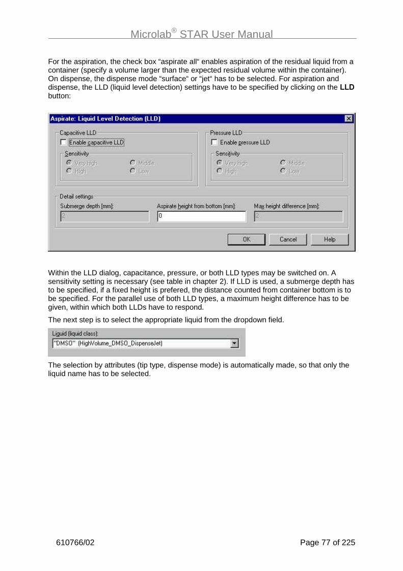
Microlab® STAR User Manual
610766/02 Page 77 of 225
For the aspiration, the check box “aspirate all“ enables aspiration of the residual liquid from acontainer (specify a volume larger than the expected residual volume within the container).On dispense, the dispense mode “surface“ or “jet“ has to be selected. For aspiration anddispense, the LLD (liquid level detection) settings have to be specified by clicking on the ��0button:
Within the LLD dialog, capacitance, pressure, or both LLD types may be switched on. Asensitivity setting is necessary (see table in chapter 2). If LLD is used, a submerge depth hasto be specified, if a fixed height is prefered, the distance counted from container bottom is tobe specified. For the parallel use of both LLD types, a maximum height difference has to begiven, within which both LLDs have to respond.
The next step is to select the appropriate liquid from the dropdown field.
The selection by attributes (tip type, dispense mode) is automatically made, so that only theliquid name has to be selected.
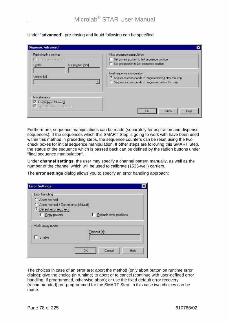
Microlab® STAR User Manual
Page 78 of 225 610766/02
Under “� .��!� “, pre-rinsing and liquid following can be specified.
Furthermore, sequence manipulations can be made (separately for aspiration and dispensesequences). If the sequences which this SMART Step is going to work with have been usedwithin this method in preceding steps, the sequence counters can be reset using the twocheck boxes for initial sequence manipulation. If other steps are following this SMART Step,the status of the sequence which is passed back can be defined by the radion buttons under“final sequence manipulation“.
Under !�������������/�, the user may specify a channel pattern manually, as well as thenumber of the channel which will be used to calibrate (1536-well) carriers.
The ������������/� dialog allows you to specify an error handling approach:
The choices in case of an error are: abort the method (only abort button on runtime errordialog); give the choice (in runtime) to abort or to cancel (continue with user-defined errorhandling, if programmed, otherwise abort); or use the fixed default error recovery(recommended) pre-programmed for the SMART Step. In this case two choices can bemade:

Microlab® STAR User Manual
610766/02 Page 79 of 225
- “Copy pattern” means that in case of an error on aspiration, the corresponding well of thedispense sequence will be left out (the pattern is kept). If “copy pattern“ is not checked,the dispense sequence positions will all be pipetted, leaving an unpipetted well at the endof the sequence.
- “Exclude error positions” means exclude the erroneous positions from aspiration anddispense sequences. If this option is enabled and an error occurs during an aspirate ordispense step, the erroneous position will be excluded from the sequence by removingthe corresponding element from the aspirate or dispense sequence. The next time thesesequences are used, the erroneous well will not be pipetted.
In addition, :��12�:�(�mode can be enabled. If this checkbox is checked, a timeout has tobe specified, after which the error dialog on runtime will automatically close down again tocontinue with the selected error handling: Abort, Cancel, or default error recovery.
���+9�����,�(����������6���� �����������$8�������������������������������������������� �������������!������������������"&����� � ���$�������� �������������� ������������������������������������ �������������������������������� ����!��������5>�C�����������9� ������������� � ���$���������� ���"�
Copy
Copy
Copy PatternChecked
Copy PatternNOT Checked

Microlab® STAR User Manual
Page 80 of 225 610766/02
B������� ���"�����&���� D$����
This SMART Step is used to automatically load the instrument deck with all labwarenecessary for the run. These commands work with autoload and manual load instruments.For a manual load instrument, the user is requested to load/unload the carriers by hand.
Dragging the ��� �command to the method tree opens up a dialog box:
The procedure for loading the instrument follows logically from our concept of sequences.Whatever carriers have to be loaded to ensure that the sequence which is used within themethod is available �� be loaded. If, for example, a sequence of samples spans 3 tubecarriers, all 3 carriers will be loaded automatically to their locations (tracks) as defined in thedeck layout.The dialog box has three main buttons. Their functions are:- to load all sequences to the deck,- to add a specific sequence which can be selected from the dropdown field, and- to remove a selected sequence.In the case of a tip sequence, the SMART Step gives you the option to read the currentposition of a tip counter, which has to be specified. In this example, the tip counter“MyStandardTips” is read and the current position of the sequence is set to the value of thetip counter.In addition, sequences may be reduced on loading (click on “show details”). If a carrier for1536-well microplates is being loaded, it may be calibrated using the channel selected in thedropdown field.

Microlab® STAR User Manual
610766/02 Page 81 of 225
Click on “Error Settings” to define the error handling for this step. This is similar to the errorhandling of the SMART Step Pipette.
To ����� the deck, use the SMART Step Unload. It is very similar to the loading step.
Here, all carriers involved in the specified sequences are unloaded from the instrument deck.

Microlab® STAR User Manual
Page 82 of 225 610766/02
B�����#� ���"�����&������,�����/��� ���
For the washing of needles, three SMART Steps are available. The idea is that needles canbe used like disposable tips without bothering about the organization of the three washmodules of a wash station.To do this, the ��� ���&�!1��& command- waits until a wash module is ready,- picks up needles from a wash station (or from a separate needle rack, which is in fact an
empty tip rack filled with needles: e.g., the lowneedle_l.rck).
Dragging the command to a method tree opens the following dialog:
The sequence requested here is the sequence running over all (three) modules of a washstation, thus having 24 positions (8 from each module). This sequence has to be generatedusing the sequence editor. The SMART Steps automatically take care of handling theindividual wash modules by incrementing the appropriate sequences in the background.
���-���C �����5@ ����� ���������&���������������%�����������������������%���������������������C������ ��������&����%�������� ���� �����������5&�@&�2&�C&=5&=@&=2&=C&:5&:@&:2&:C&������&=&:���������������������� ��

Microlab® STAR User Manual
610766/02 Page 83 of 225
The needle eject command- places the needles into the next available wash module, and- starts the wash process (on request).
For both commands channel patterns can be set manually. The error settings are againsimilar to those of the SMART Step pipette.An additional SMART Step is available to set the wash parameters; see the section on thewash station.
B�����%� ���"�����&������)�!1��/��&��� �"�������/���&�
Two further SMART steps allow you to pick up tips from a rack and then dispose of them inthe tip waste after use.Here is the dialog for the “pick up tips” step:
The dialog asks you to specify a tip sequence. You also have the option of specifying a tipcounter.

Microlab® STAR User Manual
Page 84 of 225 610766/02
Here is the dialog for the “tip eject” step:
For “channel settings” and “error settings”, see the description of previous SMART steps.
B����� ���/������&�
Now look at the ��� ��9�������. You will find that, for each deck layout or instrument youselected, there is now an additional bar containing the instrument-specific steps.
�����+��������������� �����������������������������

Microlab® STAR User Manual
610766/02 Page 85 of 225
���
��������������������������&������� �������������� ������������� ��6����8�
The table on the next two pages gives a brief outline of the available ML-STAR-specificcommands. These instrument-specific single commands are used in both the Graphical andthe HSL Method Editors.

Microlab® STAR User Manual
Page 86 of 225 610766/02
����� �!�� �!�����&������� )����������������&�!����
Initialize Initializes the instrument Waste destination,channel
Load Carrier Loads a carrier on the deck Carrier position1, racktype
Unload Carrier Removes a carrier from thedeck
Carrier position
Tip Pickup Picks up a CO-RE tip or needle Sequence, tip type,channel
Tip Eject Discards the tip into the tipwaste or the needle into thewash station or rack
Waste destination,channel
Aspirate Draws liquid from a container Sequence, volume,liquid name, channel,mix settings, LLD
1 The carrier position gives the track number on the Microlab® STAR deck where the carrier will beinserted. For microtiter plate carriers which are 6 tracks wide, the carrier position refers to the leftmostedge of the carrier.

Microlab® STAR User Manual
610766/02 Page 87 of 225
����� �!�� �!�����&������� )����������������&�!����
0��&���� Drops liquid into a container Sequence, volume,liquid name, channel,mix settings, LLD
����������'#+ Measures precise position of ahigh-density microtiter platebefore aspirating or dispensing
Carrier position,channel
��.���)�������
Moves the pipetting head to anabsolute position, or to onerelative to the current position
Mode, direction, value
����:��������
Sends a low-level firmwarecommand to the instrument
Firmware command,parameter
����������4�� ��.��
Gets the z position of the lastliquid level detection
�������� ��,���
Starts a needle wash module Name of wash module
,��������,��� Waits for the needle washmodule to be ready
Name of wash module

Microlab® STAR User Manual
Page 88 of 225 610766/02
����� �!�� �!�����&������� )����������������&�!����
������&�������
Sets the temperature of a TCC Carrier name,temperature settings
�����&�������
Retrieves the temperature of aTCC
Carrier name, bindreturn value to gettemperature in °C (seechapter about bindingreturn values)
���)���� Picks up a plate from thedefined position
Position of plate to belocated and picked upby iSWAP
)��!��)���� Sets a plate down in a definedposition
Movement type,transport mode, platesequence, sequencecounting, lid sequence,complex movementparameters
��.��)���� Transfers a plate to anothersequence
Move to sequence
�&��� ��&&�� Spreads the fingers of iSWAP’srobotic hand
Transport mode, platesequence, sequencecounting, lid sequence
����� ��&&�� Closes the fingers of iSWAP’srobotic hand
Transport mode, platesequence, sequencecounting, lid sequence
���
(���� �?������������������������� �����������������������

Microlab® STAR User Manual
610766/02 Page 89 of 225
B�#� ,�����/��������
You can now easily write a method by dragging icons from the toolbox on the left anddropping them into the method window on the right.
������ �����
Inserting a new command or double-clicking on an existing command opens the appropriatedialog to edit the command-specific parameters, for example the ���������command,used to define and assign variables:
������������������� ��
B�%� � ����/��������
A method can be edited by the usual Windows copy-and-paste techniques. Mark the step orthe block of adjacent steps within the method editor and right-click the method window toaccess the cut/copy/paste menu. To insert a step from the buffer, click on the line abovewhich the step should be inserted, and then paste.

Microlab® STAR User Manual
Page 90 of 225 610766/02
B�'� 5��������
Within a method, the user may typically wish to define and process variables. The GraphicalMethod Editor recognizes three types of variables: integers (numbers), floats (floating pointnumbers), and strings (text variables).
Variables can be newly defined within the dialogs, if they occur
• on the left-hand side of an equation (e.g. x=0, or x=t+1), or
• within edit fields that hold only one variable.
If not explicitly requested (as is the case in the “Open file” dialog), the variable types areidentified automatically. For example, f=5 will generate a variable f of type integer.
���
����������������!9"������� ��$���������&���9�������� ����������%�����������&������06��6�������������$��string�
1����� ����������������������������� ������� ������� �������� �������������
5@�������������$������� ������$������ ����������� �� ����������$� �����$�
-��������� �����&������
• � ����������������������&
• ���� ���������������������������������!6;8"�
1����� ��������������������
���������������������������������� &���������� ������ ����!6KK6"���������������� ����� ����!6K6"� �����6�,KK���������� �KK���� ��KK�����KK6�
-����� �� ���������������� �&��������0C&��02������������0�L�����������5�!� ���������"���������� �������������� &�������������9� ��� $������� ����$������������0C�3��L����02�3�
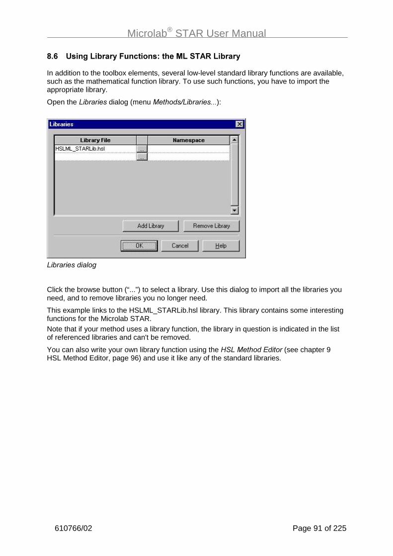
Microlab® STAR User Manual
610766/02 Page 91 of 225
B�+� $���/�������(����!�����=�����������"�������(
In addition to the toolbox elements, several low-level standard library functions are available,such as the mathematical function library. To use such functions, you have to import theappropriate library.
Open the )��������dialog (menu �����L)����������):
)����������� ��
Click the browse button (“...”) to select a library. Use this dialog to import all the libraries youneed, and to remove libraries you no longer need.
This example links to the HSLML_STARLib.hsl library. This library contains some interestingfunctions for the Microlab STAR.Note that if your method uses a library function, the library in question is indicated in the listof referenced libraries and can't be removed.
You can also write your own library function using the /�)������+�����(see chapter 9HSL Method Editor, page 96) and use it like any of the standard libraries.
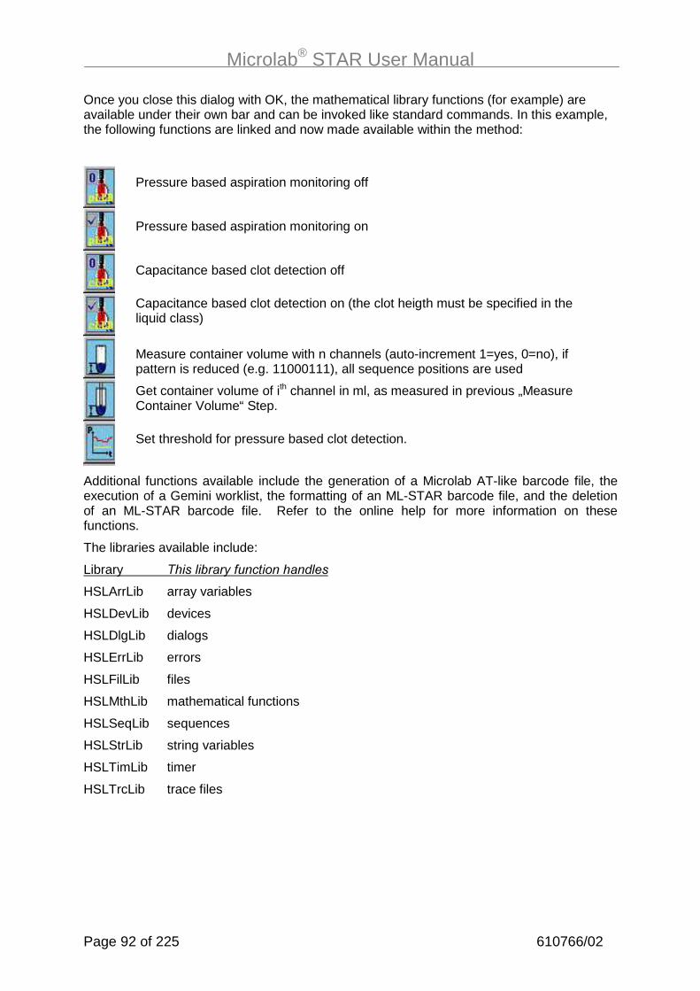
Microlab® STAR User Manual
Page 92 of 225 610766/02
Once you close this dialog with OK, the mathematical library functions (for example) areavailable under their own bar and can be invoked like standard commands. In this example,the following functions are linked and now made available within the method:
Additional functions available include the generation of a Microlab AT-like barcode file, theexecution of a Gemini worklist, the formatting of an ML-STAR barcode file, and the deletionof an ML-STAR barcode file. Refer to the online help for more information on thesefunctions.
The libraries available include:
Library ����� �����$������������� �
HSLArrLib array variables
HSLDevLib devices
HSLDlgLib dialogs
HSLErrLib errors
HSLFilLib files
HSLMthLib mathematical functions
HSLSeqLib sequences
HSLStrLib string variables
HSLTimLib timer
HSLTrcLib trace files
Pressure based aspiration monitoring off
Pressure based aspiration monitoring on
Capacitance based clot detection off
Capacitance based clot detection on (the clot heigth must be specified in theliquid class)
Measure container volume with n channels (auto-increment 1=yes, 0=no), ifpattern is reduced (e.g. 11000111), all sequence positions are used
Get container volume of ith channel in ml, as measured in previous „MeasureContainer Volume“ Step.
Set threshold for pressure based clot detection.

Microlab® STAR User Manual
610766/02 Page 93 of 225
B�-� ��� ��/���������������&�"������5�����
If an instrument step returns information, it can be bound to a variable by opening the =���������� ���dialog (select step of interest and select menu +��L=����������� �����). Forexample, the get temperature step of the temperature-controlled carrier returns thetemperature and other information:
=���������1� ������ ��
These pieces of §information can be stored in a variable for further processing or output. Thedialog generally lists the return values, each with an editable field to define the variable thereturn value is to be bound to.
B�B� ,��1��/�:����,��1�����
B�B��� ������������
Frequently, you will want to import and export worklists. The “open file” command of theMethod Editor is designed to enable such file handling. The data source type (format) isidentified from the extension of the worklist’s file name. The editor supports:
Microsoft Excel .xls
Microsoft Access Database .mdb
Text Files .txt, .csv, .tab, .asc
No other extensions are supported.
B�B��� �,��1�����8�� ���/�:������!��������3!��
You can specify a subset of the available data when you first open a Microsoft Excelworkbook. In a workbook file, you can open a single worksheet, a named range anywhere inthe workbook, or an unnamed range in a single worksheet.

Microlab® STAR User Manual
Page 94 of 225 610766/02
The following table lists the conventions for these settings.
����&����������6�!������� ���
��������������������������������������������(���3
Entire worksheet in aworkbook file
Specify the sheet as �����O, where ������isthe name of the worksheet.
��&������=�You must end the worksheet name with adollar sign ($).
Named range of cellsin a worksheet orworkbook file
Specify the named range as #�������, where#������� is the name you assigned to the range inMicrosoft Excel.
��&������=�You must name the range in Microsoft Excelbefore attempting to open it.
Unnamed range ofcells in a singleworksheet in aworkbook file
Specify the sheet you want to open as �����O andthe range as -���: (�����=)��: (�����. Forexample, to access cells A1 through Z256 in a worksheetcalled Sales, you would specify Sales$A1:Z256.
����&����������6�!����:���� �������������(���3
Entire worksheet in aworkbook file
Specify the sheet as �����, where ������is thename of the worksheet.
��&������=�You must ��� end the worksheet name with adollar sign ($).
����&&�� ���������6�!� �������������������������������������(���3
Append to an �3�����/worksheet in aworkbook file
Specify the sheet as �����O, where ������isthe name of the worksheet.
��&������=�You must follow the worksheet name with adollar sign ($).
Append to a ����(���3�����/ worksheet ina workbook file
Specify the sheet as �����, where ������is thename of the worksheet.
��&������=�You must ��� follow the worksheet name witha dollar sign ($).
���
7��������������$����� ���������������9��������9������������������&��� ����&���������������������������������-�������������������������� ��&���$������������+9� ������������
������������� ����������������� ���������9� ��� ������������� ,�9&������&��

Microlab® STAR User Manual
610766/02 Page 95 of 225
B�;� ,�����/����!�2�(&������� ���������+2���������!���������"
As discussed in chapter 3.2.1, the 16-channel Microlab STAR is intended to be used as abatch-like processor. This means all 16 channels should aspirate and dispensesimultaneously, to allow maximum parallelization and highest pipetting speed. In this case,the reduced random access space of a 16-channel Microlab STAR does not cause anyproblems.
To achieve a batch-like process, all sequences involved must consist of blocks of at least 8,or better 16 positions. Sequence positions within a block must have
• the same x-positions, and
• decreasing y-positions from channel 1 (rear-most) to 16 (front-most).
To program a method using single steps
• Select the option “keep pattern” within the “Channel Settings” dialog in all single steps (tippick-up, tip eject, aspirate, dispense). Do ��� use the option “all sequence positions”.
• Even if an error occurs and “Exclude Channel” is selected as an error recovery, thepattern will be kept.
To program a method using SMART Steps
• Select “Copy Pattern”
• Do ��� select “Exclude Erroneous Positions”.
• If sequences are reloadable (in runtime during the pipette command), �����!� the option“reducible by user” to maintain the original block-wise structure of the sequences.

Microlab® STAR User Manual
Page 96 of 225 610766/02
;� 8�������� �� ����
The HSL method editor gives the user access to the underlying HSL code, offering higherflexibility for programming methods. Usually this method editor is used only to customizemethods written with the graphical method editor. Of course, a complete method can also bewritten using the HSL method editor.
The /�)������+���� is a general-purpose text-like editor that can be used to createmethods based on�/�) (/��()�*#���������)������) for any instrument system. It is asub-component of the User Software. Parameters for instrument steps are entered usingdialog boxes, and may include variables. The editor makes use of the same instrument-specific steps as the graphical method editor. It allows methods to be created, saved,modified and printed.
To use the /�)������+����
• Open Windows Explorer
• Go to folder \Program files\Hamilton\Bin
• Create a shortcut to the executable file named HxHSLMetEd.exe on the desktop.
Use the /�)������+���� shortcut you have placed on the desktop to start it. Then use the#��menu to create a new method based on an existing deck layout, or open a previouslywritten method by means of the File->Open menu.
/�)������+����

Microlab® STAR User Manual
610766/02 Page 97 of 225
The /�)������+�����window is divided into 3 sections:
The �� ������� on the right is a general-purpose text-like editor window containing themethod written in /�). The general syntax used in HSL is the C/C++ notation.Instrument steps are shown with a gray background. For safety reasons it is not possible tochange or type in these commands directly. Double-clicking an instrument step displays astep dialog where you can change specific parameters. To see all step parameters in the�����1��, use 1���� ������ in the 1�� menu.
The ��������������on the left offers various elements that can be used to build themethod, grouped by the following bars:
�������� �������
�);����
!���9��� ����������"
Each device defined in the method shows its own instrument barcontaining all the steps the instrument can execute.
������ Contains the common /�) language elements such as �� �, ���, ���������� , etc.
�����$�������� A set of standard library functions such as mathematicalfunctions, trace functions, string manipulation functions etc.
������ � Different variable types.
All these elements can be used by dragging them from the appropriate bar and droppingthem into the �����1��,�or by using the (����menu. Alternatively, language elements,library functions and variables (but not instrument steps) can also be typed directly into the�����1��.When an instrument step is inserted, the appropriate step dialog is displayed so you candefine the specific parameters needed.After writing a method, invoke Syntax Check from the ��� � menu to check your method.
The �#� �������$ ������at the bottom shows the results of the syntax check, ifperformed. If any error is listed in this view, double-clicking on it will set the cursor to theincorrect statement in the �����1��.
If the HSL method editor is used to edit a method that was written with the graphical methodeditor, insert the HSL code only between two adjacent comment lines. Leave the commentlines and all code in between unchanged. Save your changes and close the HSL methodeditor. If this method is reopened with the graphical method editor, your changes will bevisible as a greyed-out, unchangeable HSL code block.

Microlab® STAR User Manual
Page 98 of 225 610766/02
�9�"���������
Run Control enables you to execute your methods.During execution of a method, the instrument steps are automatically logged and displayedin the log window as well as written in a trace file with the same name as the relevant layoutfile. The Run Screen shows a static view of the deck layout. Because there is an open n:nrelation between methods and deck layouts (see chapter 4), the Run Control may start eitherdeck layouts (*.lay), or methods (*.hsl). A further alternative is to start linked methods (*.cmt).The run control may be accessed by the shortcut buttons of deck layout or method editor.
Then, the method of interest is automatically loaded into the Run Control. Alternatively, theRun Control may be started by double-clicking the “Microlab STAR Run ” shortcut on thedesktop. Then, the method (or the deck layout) of interest must be opened from the runcontrol by selecting File->Open from the menu.
On opening the method, a dialog box appears for a period of time, informing the user that themethod is being parsed, i.e., analyzed. This procedure may take up to a minute, dependingon the size of the method.
.�������������

Microlab® STAR User Manual
610766/02 Page 99 of 225
After loading and parsing a method you can use the ����button to execute it.
����������$������
Each executed instrument step is logged in the log window.
The choices within Run Control are
• To start a method
• To abort a method
• To use single steps (system pausing after each single step)
• To pause a method (to be continued later)
Clicking on the deck layout view of the Microlab STAR within Run Control adds the Toolsmenu to the menu list. Here you will find shortcuts to access the configuration and liquideditor. The configuration editor is used to switch between simulation and instrument mode.
���
������� �������&�� ��$�������������������������������� ����!�������������� �����������"�����B������������������������������������� � ���������������������������������� � ������������

Microlab® STAR User Manual
Page 100 of 225 610766/02
�9�������� ����1��/
The Microlab STAR user software allows you to link different methods together prior tostarting the merged or linked run. To do so, open the Deck Layout Editor and select “File->Method Linking”. A dialog appears:
Select the first method of interest and click on the buttons to add the method to the list on theright-hand side. It is recommended to select HSL files (.hsl) rather than layout files (.lay) ormethod files (.med).
Select File->Save to generate a chained method file (.cmt). Close the dialog by clicking onexit. Close the deck layout editor. Open the Run Control by double-clicking the shortcut onthe desktop. Open the newly created .cmt file and execute it.

Microlab® STAR User Manual
610766/02 Page 101 of 225
���������!���������"���4�� �� ����
����� ����!�&�������4�� �������
As mentioned in chapter 2 The Art of Pipetting, page 12, the background parameters forpipetting are managed using liquid classes. A liquid class is a set of parameters specifyingthe aspiration and dispense behavior appropriate for a given liquid (e.g. water, DMSO,.... ). Inall aspirating and dispensing steps, a valid liquid class must be selected.
Standard liquid classes will be supplied along with the User Software (Water, DMSO,Glycerine, Precinorm). The standard liquid classes cover a wide range of applications, andyou will probably not need to make any changes to the parameter settings.
For special applications, you can define your own liquid class. This custom liquid class canbe used just like the pre-defined classes.
Defining liquid classes independently serves to simplify the steps in the method and allowsthe complete set of parameters to be defined once for all pipetting tasks.
To define a custom liquid class, and to display the parameters of the liquid classes defined,the Liquid Editor should be used.
����� ��� ����/���4�� �0������
To start the Liquid Editor, select "ML_STAR Liquid Editor" from the Tools menu of the DeckLayout Editor. The Liquid Editor start window is displayed:
)�%����+���������������
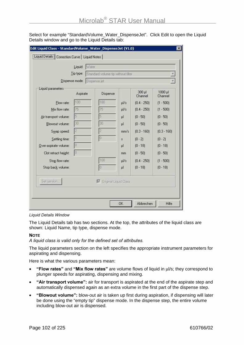
Microlab® STAR User Manual
Page 102 of 225 610766/02
Select for example “StandardVolume_Water_DispenseJet”. Click Edit to open the LiquidDetails window and go to the Liquid Details tab:
)�%������� ��������
The Liquid Details tab has two sections. At the top, the attributes of the liquid class areshown: Liquid Name, tip type, dispense mode.
����� �%����� ��������� ����� $�������������������������
The liquid parameters section on the left specifies the appropriate instrument parameters foraspirating and dispensing.
Here is what the various parameters mean:
• G���:������H�and�G��3����:������H are volume flows of liquid in µl/s; they correspond toplunger speeds for aspirating, dispensing and mixing.
• G���������&����.�����H= air for transport is aspirated at the end of the aspirate step andautomatically dispensed again as an extra volume in the first part of the dispense step.
• G���:����.�����H=�blow-out air is taken up first during aspiration, if dispensing will laterbe done using the “empty tip” dispense mode. In the dispense step, the entire volumeincluding blow-out air is dispensed.

Microlab® STAR User Manual
610766/02 Page 103 of 225
• G�:�&��&�� H�is the speed at which the dispensing head is drawn up out of the liquid.
• G�������/�����H�is the time the dispensing head has to wait in the liquid afteraspiration/dispensing until it begins to withdraw.
• G�.��2��&������.�����H�is a kind of pre-wetting volume: on aspirating e.g. 20µl of liquid,first more than 20µl is aspirated (20µl+Over Asp. Vol.), so as to pre-wet the tip. Then thisvolume is immediately dispensed again (still in the aspirate step).
• G���������!�����/��H= a parameter for recognizing blood clots, which determines howhigh the dispensing head is allowed to travel up out of the liquid if there is a residualcLLD signal after aspiration. It is measured in mm from the height of the liquid surfaceupwards. If this distance is exceeded, an error message is generated.
• G���&����:�����H=�dispensing speed of the plunger (expressed as a stream of liquidvolume in µl/s), at which the dispensing step terminates abruptly. If “dispense flow rate“ isequal to “stop flow rate“, the dispense breaks off abruptly after dispensing the volumewithout slowing down beforehand. If “Stop flow rate“ is equal to zero, the plungermovement becomes gradually slower during the dispense until it stops.
• G���&���!1�.�����H= volume which is aspirated again immediately after the dispense(as part of the dispense step). This volume is aspirated automatically as quickly aspossible.
The next tab defines the correction curve:

Microlab® STAR User Manual
Page 104 of 225 610766/02
A correction curve has a target volume and a corrected volume. The “target volume“ is thevolume to be dispensed. The “corrected volume“ is the volume (plunger travelling distance xdiameter) that actually needs to be aspirated for this purpose. In aspirate or dispense steps,the “target volume“ which will actually be dispensed into the vessel must be entered. Thecorrected volumes are usually determined gravimetrically. Accordingly, a corrected volume of105 µl does not mean that 105 µl of liquid will be dispensed. When the tip is emptied, 100 µlare dispensed. The correction is mainly due to the properties of the air column above theliquid.
The definition of liquid classes allows you to pipette any given liquid with high accuracy.Liquid classes are also available from HAMILTON’s Application Engineering Group forcustom purposes, if you need them.
���
����������� �%����� ��������� �������������������������������!;"���������� ���������� �%����� ���������������������$����������$������������&����������������������������������
���#� ��0������/�����������4�� �����
To define a custom liquid class, select a pre-defined liquid in the Liquid Editor start windowand click Create. The Copy Liquid window pops up:
:��$�)�%����������
Type in the name of the new custom liquid class and click OK.
Back in the Liquid Editor start window, select your new liquid class and click Edit. Now all theparameter input fields in the Liquid Details window are active, so you can make whateverchanges you require.
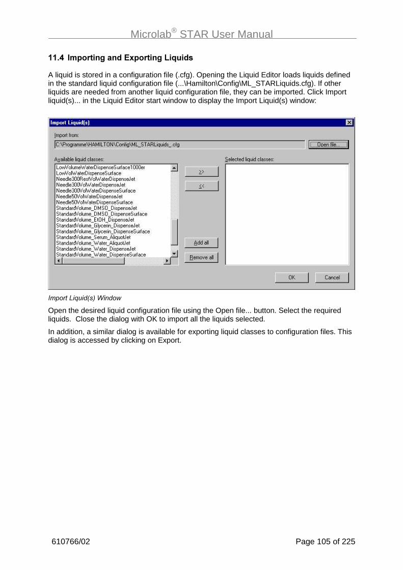
Microlab® STAR User Manual
610766/02 Page 105 of 225
���%� ��&�����/��� ��3&�����/���4�� �
A liquid is stored in a configuration file (.cfg). Opening the Liquid Editor loads liquids definedin the standard liquid configuration file (...\Hamilton\Config\ML_STARLiquids.cfg). If otherliquids are needed from another liquid configuration file, they can be imported. Click Importliquid(s)... in the Liquid Editor start window to display the Import Liquid(s) window:
(�����)�%���!�"�������
Open the desired liquid configuration file using the Open file... button. Select the requiredliquids. Close the dialog with OK to import all the liquids selected.
In addition, a similar dialog is available for exporting liquid classes to configuration files. Thisdialog is accessed by clicking on Export.

Microlab® STAR User Manual
Page 106 of 225 610766/02
�����!�������5��P��������� �5�!�����(����
����� ����/���������������5�
The Microlab AVS is a separate software component that comes with the vacuum box. It hasto be installed separately. For convenience, you may wish to add the vacuum boxpermanently to the deck layout.
The following example describes the programming of the Automated Vacuum System. As afirst step to writing the method, a deck layout with an integrated vacuum box has to becreated. Therefore, open the Hamilton Deck Layout Editor window and select “New“ from the“File“ menu. This window appears:
Select the Microlab STAR instrument and click OK. An “empty“ STAR deck layout willappear.
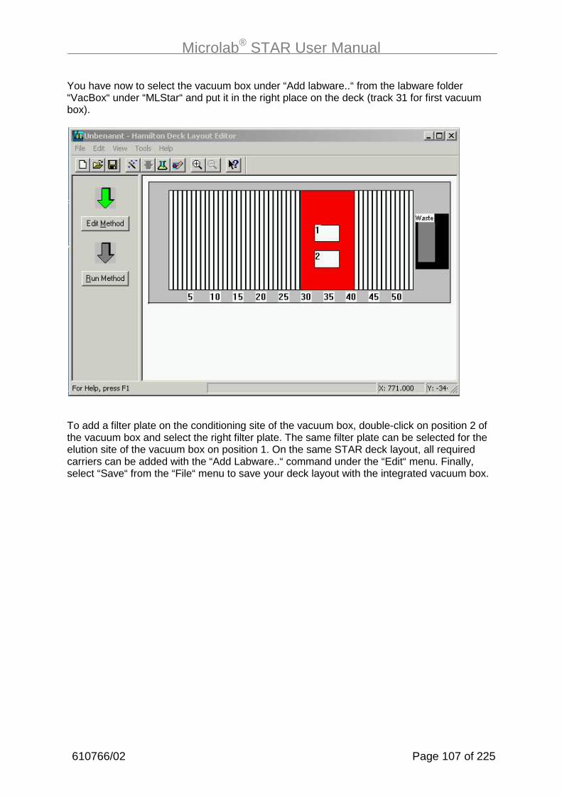
Microlab® STAR User Manual
610766/02 Page 107 of 225
You have now to select the vacuum box under “Add labware..“ from the labware folder“VacBox“ under “MLStar“ and put it in the right place on the deck (track 31 for first vacuumbox).
To add a filter plate on the conditioning site of the vacuum box, double-click on position 2 ofthe vacuum box and select the right filter plate. The same filter plate can be selected for theelution site of the vacuum box on position 1. On the same STAR deck layout, all requiredcarriers can be added with the “Add Labware..“ command under the “Edit“ menu. Finally,select “Save“ from the “File“ menu to save your deck layout with the integrated vacuum box.

Microlab® STAR User Manual
Page 108 of 225 610766/02
There is also a possibility to permanently change the default STAR deck layout, which mightbe helpful sometimes. This can be done by modifying the configuration. To integrate thevacuum box in the configuration of the ML STAR, you have to do the following: open theHamilton Deck Layout Editor window and select “Open“ from the “File“ menu. Then open the“Config“ folder and change the “Files of type:“ to “Deck Template“.
From the three different available deck layouts select the „ML_STAR2.tpl“ and open it. Selectthe vacuum box under „Add labware…“ and put it on the right place on the deck. Select “File“and click “Save“. Your default Microlab STAR deck layout is now changed. Whenever youopen a new STAR deck layout, the vacuum box will already be placed on the deck.
Close the Hamilton Deck Layout Editor and open the Hamilton Method Editor. Select “New“under the “File“ menu and save your method with a new name. Click on “Instruments…“under the “Method“ menu.

Microlab® STAR User Manual
610766/02 Page 109 of 225
Click on the grey Deck Layout File button associated with your Microlab STAR instrument. Alist of deck layouts will appear. Select the Microlab STAR deck layout you wish to associatewith this method. The Layout window reappears with the selected layout file showing.Afterwards select the „VacuumBox“ instrument in order to get all the specific vacuum boxcommands.
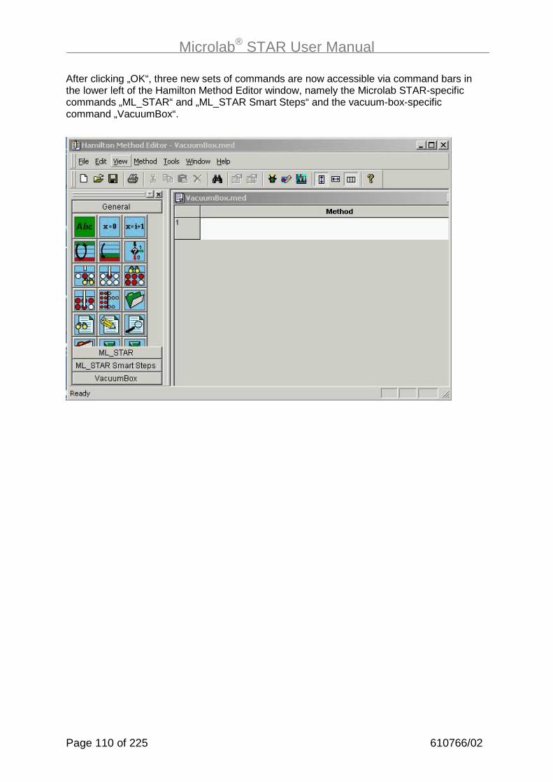
Microlab® STAR User Manual
Page 110 of 225 610766/02
After clicking „OK“, three new sets of commands are now accessible via command bars inthe lower left of the Hamilton Method Editor window, namely the Microlab STAR-specificcommands „ML_STAR“ and „ML_STAR Smart Steps“ and the vacuum-box-specificcommand „VacuumBox“.

Microlab® STAR User Manual
610766/02 Page 111 of 225
���������� �����������5�
There are three commands associated with running the vacuum box. These are inalphabetical order and are described below.
Empty waste command:
Empty waste
This command turns on the waste pump inside the vacuum box controller so that the wastetray in the conditioning chamber can be evacuated. Select the vacuum box to evacuate.Vacuum box number 1 is the default. The pump duration will need to be determined by trialand error. Generally, 25 seconds are adequate for emptying a full waste tray (200 ml). If thewaste bottle is full when this command is running, an error dialog box will appear. The userthen can empty the waste bottle and continue the program. Variables can be used for thevacuum box number and duration of pumping action.
���
���������$������������$����@33� ��.�������$�����������������������������9����������������������$���������&�������������$������������ ���

Microlab® STAR User Manual
Page 112 of 225 610766/02
Move command:
Move
This command moves the carriage from one chamber to the other. Select the chamber overwhich the carriage is to be moved. The conditioning chamber is in front and the elutionchamber in rear. If the vacuum box is not yet initialized when it receives its first “Move“command, it will initialize first and then move the carriage to the desired chamber. If it isalready at the position specified in the “Move“ command, the carriage will not move.
Vacuum command:
Vacuum
This command runs the vacuum pump inside the vacuum box controller. The vacuum boxnumber and the chamber have to be selected.
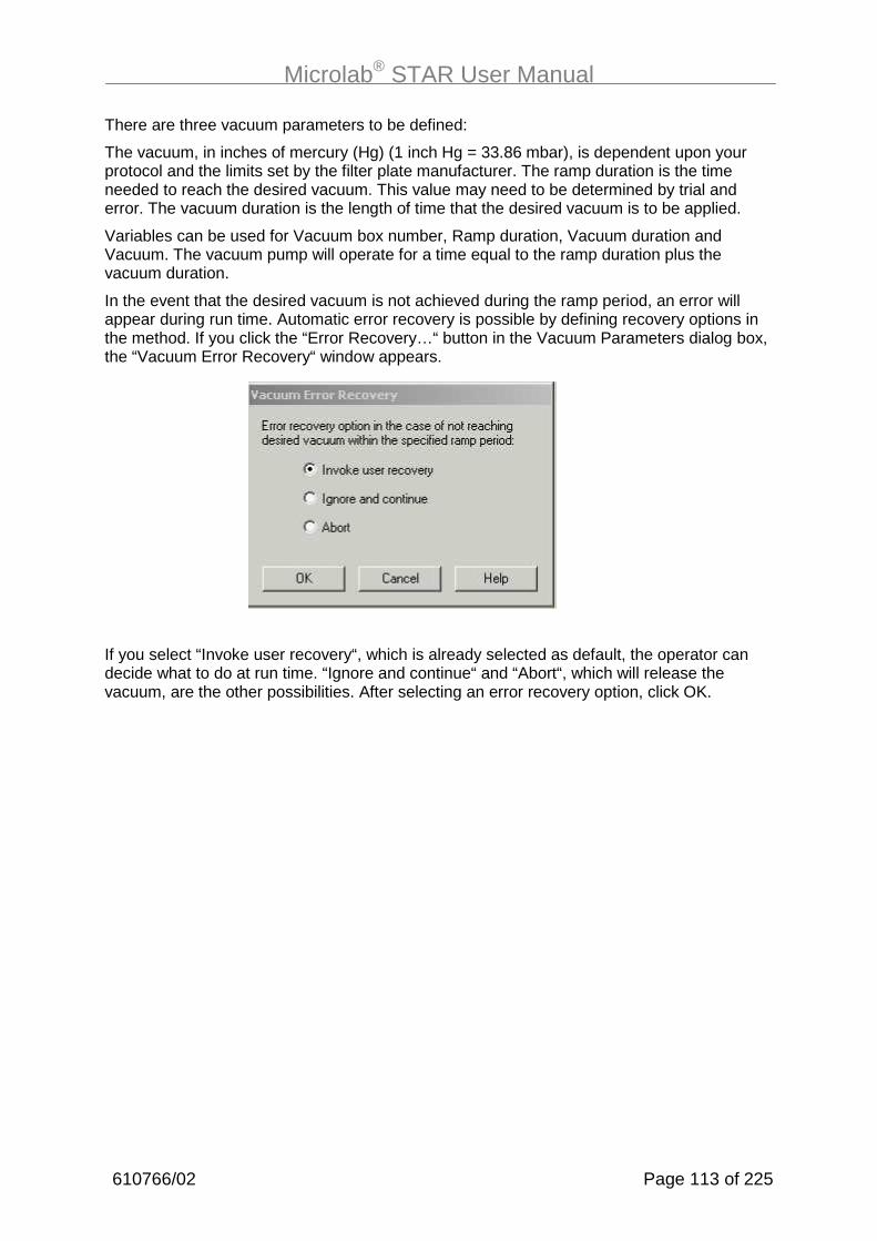
Microlab® STAR User Manual
610766/02 Page 113 of 225
There are three vacuum parameters to be defined:
The vacuum, in inches of mercury (Hg) (1 inch Hg = 33.86 mbar), is dependent upon yourprotocol and the limits set by the filter plate manufacturer. The ramp duration is the timeneeded to reach the desired vacuum. This value may need to be determined by trial anderror. The vacuum duration is the length of time that the desired vacuum is to be applied.
Variables can be used for Vacuum box number, Ramp duration, Vacuum duration andVacuum. The vacuum pump will operate for a time equal to the ramp duration plus thevacuum duration.
In the event that the desired vacuum is not achieved during the ramp period, an error willappear during run time. Automatic error recovery is possible by defining recovery options inthe method. If you click the “Error Recovery…“ button in the Vacuum Parameters dialog box,the “Vacuum Error Recovery“ window appears.
If you select “Invoke user recovery“, which is already selected as default, the operator candecide what to do at run time. “Ignore and continue“ and “Abort“, which will release thevacuum, are the other possibilities. After selecting an error recovery option, click OK.

Microlab® STAR User Manual
Page 114 of 225 610766/02
���#� )��������)��!�����/�:���������5�
We now discuss a sample program to illustrate the use of the vacuum box software.
This could be a part of a normal plasmid DNA isolation protocol combined with a PCR setup.It is very useful to work with parallel processes using the vacuum box. During the vacuumprocedures, the Microlab STAR robot goes on with pipetting and thus saves time.Accordingly, this section will also explain how to use the parallelism within the MicrolabSTAR User SW. The first step in our program is “initialize”. Then come the following steps:

Microlab® STAR User Manual
610766/02 Page 115 of 225
Let’s discuss the individual steps of this method now.
Drag the parallel process icon. A dialog appears to start parallel process No 1. Enter a namefor the parallel process and click OK. The method editor now shows the bifurcation of thenormal and the first parallel process. The STAR SW supports nested parallel processes.
Drag the Move Step of the vacuum box to the first line of the parallel process.
Move the carriage of vacuum boxnumber 1 to the conditioning site.
Click OK.
Now set the vacuum parameters:
Apply a vacuum of 5 inches of mercury onthe conditioning site for a total of 40seconds.
(10 10 seconds ramp duration plus 30seconds vacuum duration.

Microlab® STAR User Manual
Page 116 of 225 610766/02
Now empty the waste of the vacuum box:
Empty waste on the conditioning site for20 seconds
Finally, end the first parallel process:
End of parallel process1 with all thevacuum box commands
The bifurcation within the method editor ends after this step.
To process a plate, for example, with the pipetting channels of the microlab STAR, addpipetting steps to the normal process (left side of the bifurcation).

Microlab® STAR User Manual
610766/02 Page 117 of 225
�#������ ��������!���������"
�#����.��.��:
Most of the instrument’s day-to-day operations will be driven by methods, so it is importantthat they are correctly defined and easy to operate. Programmed methods are stored as alinked set of ASCII files in the Methods sub-directory on the hard disk. They can be opened,edited and saved either in the text-like HSL Method Editor (9�/�) Method Editor, page 96) orin the Graphical Method Editor (D�I������� ������+����, page 66).
The present chapter takes a “cookbook” approach. It teaches you how to program a numberof simple methods typically used in laboratories. By following these steps, you will becomefamiliar with the layout and workings of the software and can then modify the suggestedmethods to suit your own particular requirements, or program new methods based loosely onthose suggested. The scope of the complete command language is rather like that ofcommon higher programming languages. For details, refer to the ����� ������������������ , as incorporated in the online help.
����%�������������������������������� �������������������������
�������+��������� �����������������������������?������
������������������������� ��������� �����������������
All sample methods explained in this manual are available in the “\DemoMethods_MLSTAR“directory following installation of the Microlab STAR User Software.
�#���������������� �����&(������)��������)�����$���/����"�����&�
The method we are going to describe first “copies” wells, i.e. aspirates liquids from wells on aplate and dispenses them to the corresponding wells on another plate (A1→A1’ ...H12→H12’). The transferred volume will be 50 µl. The method name is “OnePlateToPlate“.The method uses new CO-RE tips for every well. We start with an empty target plate.
First, an appropriate deck layout has to be created and saved as “OnePlateToPlatePipette”(.lay). The deck layout for this method is shown in the picture on the next page.
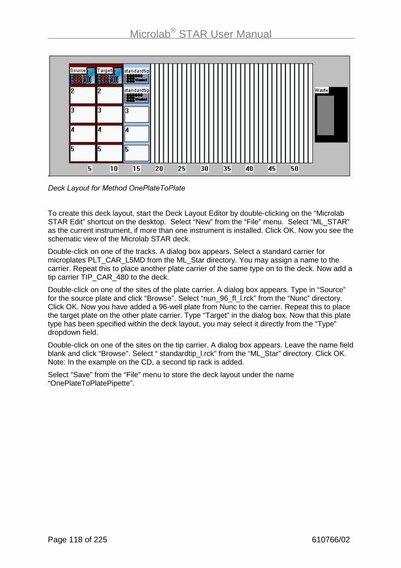
Microlab® STAR User Manual
Page 118 of 225 610766/02
����)�$������������*�. ���. �
To create this deck layout, start the Deck Layout Editor by double-clicking on the “MicrolabSTAR Edit” shortcut on the desktop. Select “New” from the “File” menu. Select “ML_STAR”as the current instrument, if more than one instrument is installed. Click OK. Now you see theschematic view of the Microlab STAR deck.
Double-click on one of the tracks. A dialog box appears. Select a standard carrier formicroplates PLT_CAR_L5MD from the ML_Star directory. You may assign a name to thecarrier. Repeat this to place another plate carrier of the same type on to the deck. Now add atip carrier TIP_CAR_480 to the deck.
Double-click on one of the sites of the plate carrier. A dialog box appears. Type in “Source”for the source plate and click “Browse”. Select “nun_96_fl_l.rck” from the “Nunc” directory.Click OK. Now you have added a 96-well plate from Nunc to the carrier. Repeat this to placethe target plate on the other plate carrier. Type “Target” in the dialog box. Now that this platetype has been specified within the deck layout, you may select it directly from the “Type”dropdown field.
Double-click on one of the sites on the tip carrier. A dialog box appears. Leave the name fieldblank and click “Browse”. Select “ standardtip_l.rck” from the “ML_Star” directory. Click OK.Note: In the example on the CD, a second tip rack is added.
Select “Save” from the “File” menu to store the deck layout under the name“OnePlateToPlatePipette”.

Microlab® STAR User Manual
610766/02 Page 119 of 225
Click on “Edit Method” to open up the Graphical Method Editor.
From the method editor's "Method" menu, select "Instruments" to link the deck layout to themethod as described in the chapter “The graphical Method Editor”. A window pops up:
Choose “OnePlateToPlatePipette.lay” as the deck layout (browse by clicking the “...” button)and click OK. Only now are the instrument-specific commands loaded into the methodeditor. They can be accessed by clicking on the “ML_STAR SMART Steps” toolbar in thetoolbox window.
You can easily write the method by dragging icons from the toolbox on the left and droppingthem in the method window on the right. The resulting method will look like this:
���
+9� ���� �������!�����$���� ����������������������������"��������������������$������&�����������������$��(����� ��������������������������&����������������������������������������������������������������� �������������������������� $������������������������� ��������������� � ����������� ��������� ���������

Microlab® STAR User Manual
Page 120 of 225 610766/02
First, drag the SMART Step load into the method window:
Click on “Add all sequences” to make sure all carriers are going to be loaded on to theinstrument deck. Click OK. If you want to decide at runtime which or how many of the wells ofthe source plate are to be transfered to the target plate, click on “Show Details” and enablethe checkbox “Reducible” for the source sequence:
Click OK again.
For an instrument with autoload option, this command loads the carriers automatically ontothe instrument deck during runtime. For a manual load instrument, this command requeststhe user to load the carriers for runtime.

Microlab® STAR User Manual
610766/02 Page 121 of 225
Now program your pipetting. Drag the SMART Step pipette to the line below the loading step:
Choose “Standard Pipette Procedure” and “Simple” as a pipetting mode, because it’s asimple transfer from plate to plate. The volume to be transfered is 50 µl, the residual volumeis 0. Select the tip sequence ML_STAR.Tips from the dropdown field. The tip handlingchosen here is to take new tips for each sample (which is for 50 µl and standard tips, thesame as “after each sample”). Now select the aspiration sequence as the controllingsequence. Even if both sequences have the same length initially, it makes sense to choosethe aspiration sequence as the controlling one. Remember that on loading this sequence thesequence may be reduced to less than 96 positions. Then, only the current number of wellsis transfered to the target plate. Both aspiration and dispense sequence are set as notreloadable. The dispense mode is to dispense in a ”jet”, because initially, the target plate isassumed to be empty. The liquid class used in this example is water.

Microlab® STAR User Manual
Page 122 of 225 610766/02
On aspiration, you may use capacitance-based LLD. Click on the LLD button:
Set the settings according to this example. Click OK. On dispense, switch off the LLD anddispense to a fixed height (2 mm from bottom):
Accept the defaults for the settings under Advanced and for the error settings. Click OK.Click Finish in the SMART Step dialog. A window appears showing a summary of yoursettings. Click OK.

Microlab® STAR User Manual
610766/02 Page 123 of 225
Finally, drag the SMART Step Unload to the line below the pipette step:
Click on “Add all Sequences” to add all sequences to the unload step. Click OK.
Within the method editor, click File->Save to store your method.
Your first method is ready to go. See the chapter about running the STAR to see how to runyour method.
Microlab® STAR User Manual
Page 124 of 225 610766/02
�#�#� �������������� �����&(������)��������)�����:�������/������&�
The method we are now going to describe does exactly the same as the method“OnePlateToPlatePipette“ described in section 13.2. The only difference is that the methodis now written using single steps, to illustrate the difference. No sample reduction is possiblehere.
First, create the deck layout in the same way as described for the method“OnePlateToPlatePipette”. This time, save it under the name “OnePlateToPlate” (.lay).
Click on Edit Method. Link the deck layout “OnePlateToPlate” (.lay) to your new method, asdescribed above.

Microlab® STAR User Manual
610766/02 Page 125 of 225
Only now are the instrument-specific commands loaded into the method editor. They can beaccessed by clicking on the “ML_STAR” toolbar in the toolbox window.
You can easily write the method by dragging icons from the toolbox on the left and droppingthem in the method window on the right. The resulting method will look like this:
���:��$������. ����. ����������������� �����

Microlab® STAR User Manual
Page 126 of 225 610766/02
Let’s start to construct this method. Under the “ML_STAR” toolbar, drag “Initialize” to themain window. A window pops up:
Click OK to initialize the instrument in the first step. The waste sequence is selected to ejecttips from the channel during initialization. Always use manual sequence counting forinitialization (see below). Set the “Always initialize” switch to “On”, to make sure theinstrument is being initialized prior to each run.
Throughout all single steps, the channel pattern to be used may be specified manually.Clicking on “Channel Settings” opens the following dialog:
You may either deselect specific channels manually by clicking on the check boxes, or checkthe box “selection as variable”. Then the channel pattern can be defined as a (string) variablehaving a 1 for each active and a 0 for each inactive channel, e.g. “11100011”. Havingdeactivated a channel, the question arises whether to pipette all sequence positions with theremaining channels (select (1) All sequence positions) or to leave out the correspondingwells (select (2) channel pattern). Click OK to accept the settings.

Microlab® STAR User Manual
610766/02 Page 127 of 225
���
=������$������������ ��������������������������&����$���������������� �?��
Drag “Load Carrier” to the next line in the method. For an instrument with autoload option,this command loads the carriers automatically onto the instrument deck during runtime. For amanual load instrument, this command requests the user to load the carriers for runtime.
Specify the name of the carrier to be loaded. The plate barcodes are stored under the defaultfile name “barcode_1.txt”. The positions on the deck are automatically retrieved from thedeck layout on runtime. Click OK. (Note that the checkbox “barcode trace “ within theconfiguration editor must be checked to generate this file).
Repeat the Load Carrier command for the other plate carrier and the tip carrier.
To copy the whole source plate and not just the first 8 wells to the target plate, the tip pick-up, aspiration, dispense, and tip eject steps have to be performed 12 times. This can beachieved by a loop. Drag the Loop command to the next line of the method window. The loopstatement consists of two lines, a “begin loop” and an “end loop” statement. Whatever codeis inserted between these two statements will be looped.

Microlab® STAR User Manual
Page 128 of 225 610766/02
The loop dialog window looks like this:
A loop can be performed looping over a fixed number of iterations, over an expression(repeat while the statement in the expression is true), a sequence, or a file (until the end-of-file is reached). Here, we loop over the source (plate) sequence. This means, that the loopwill continue until all sequence positions (the 96 wells) of the source plate have been used.Then, the loop will stop. Choose the default “after loop” for the “Reset Sequence” option toreset the sequence “source” to the initial position (1) after the loop is done. If you pipette laterto the same sequence (“source”), the sequence will then start at the first well again.
���
M����������������$��� �����������%���&����%��������������������������� �����(��$��� ��������������������%���&����������%��������� ������������ �������

Microlab® STAR User Manual
610766/02 Page 129 of 225
Under the “ml_star” toolbar, drag “TipPickUp” to the position between the two loopstatements.
A dialog box appears. Choose sequence “ml_star.Tips” and sequence counting "Automatic".Sequence counting “automatic” means that after pick-up takes place from the first eightsequence (tip) positions, the tip sequence is automatically incremented. Sequence counting“manually” means that the sequence used in this step will not be incremented automatically;during the next tip pick-up process, the positions within the tip rack already used will be usedagain. Therefore, we select “Automatic” to increment the sequence automatically by thenumber of channels used for the tip pick-up. Next time, tip pick-up will start with the next(unused) 8 positions in the same tip rack. Click OK.

Microlab® STAR User Manual
Page 130 of 225 610766/02
Now drag Aspirate to the line below the tip pick-up step. A dialog box appears.
For sequence, choose “ml_star.Source” to aspirate from the source plate. Select "Automatic"as sequence counting. For volume, enter 50 µl. Select “Aspiration” as the aspiration mode.Choose “Standard volume tip without filter” for the tip class and “Dispense jet” as dispensemode. Then choose an item from the “Liquid class” dropdown list. (For questions about theseparameters, refer Chapter 2 of this manual, “The Art of Pipetting”.) Select "medium" as thecapacitive LLD sensitivity. Type in 1.0 (or 1) as additional submerge depth. Click "Advanced".A window appears:

Microlab® STAR User Manual
610766/02 Page 131 of 225
Set “liquid following during aspirate and mix” to “on”, allowing the channel to follow the fallingliquid level during aspiration. You may now enter the settings for mixing.
The “mix position” is the submerge depth used for mixing, moving the tip downwards fromthe current z-position.
Click OK to accept the values. Click OK in the aspirate window.
Now drag Dispense to the position below the aspirate command. A dialog box appears:
Choose “ ml_star.Target” as sequence to dispense to the target plate. Choose sequencecounting “automatic”. Enter 50 µl for the volume again. Select the dispense mode “Jet ModeEmpty Tip”. Select “ off” as the capacitive LLD setting - because the target plate is empty -and enter 2 mm as “liquid level”, corresponding to a height of 2mm for the dispense,measured from the container bottom.
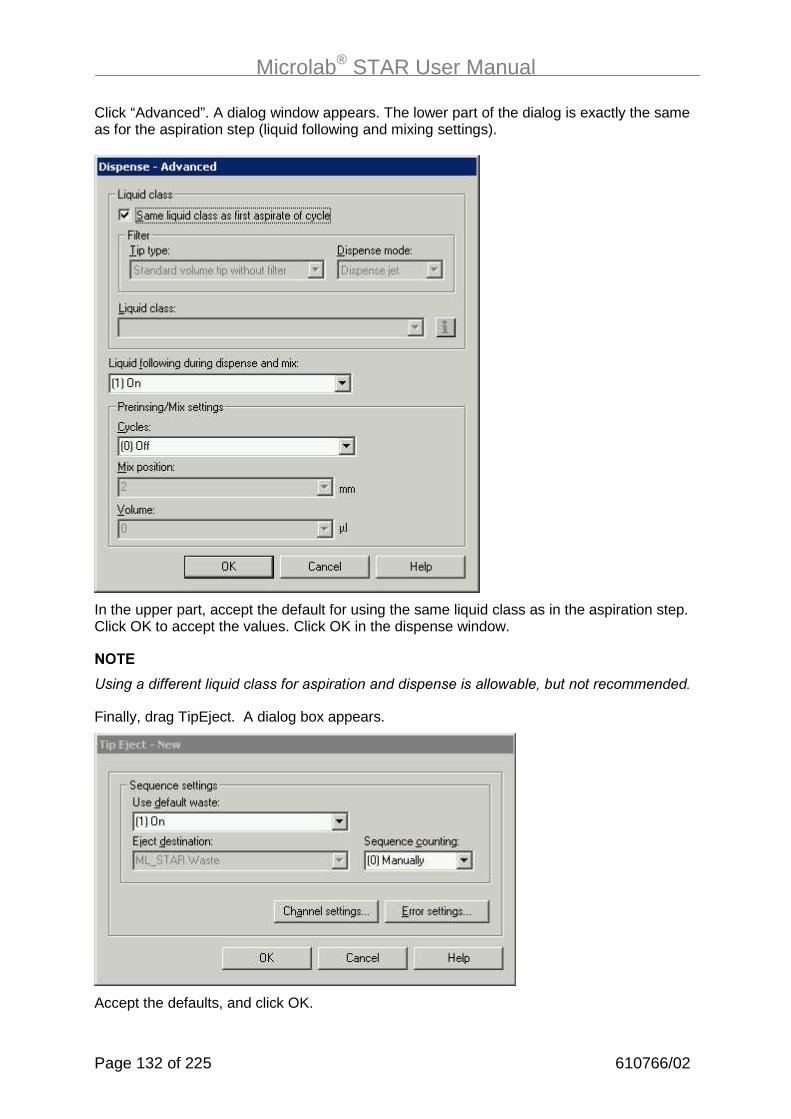
Microlab® STAR User Manual
Page 132 of 225 610766/02
Click “Advanced”. A dialog window appears. The lower part of the dialog is exactly the sameas for the aspiration step (liquid following and mixing settings).
In the upper part, accept the default for using the same liquid class as in the aspiration step.Click OK to accept the values. Click OK in the dispense window.
���
��������������� �%����� ��������������������������������� ���� &����������������
Finally, drag TipEject. A dialog box appears.
Accept the defaults, and click OK.

Microlab® STAR User Manual
610766/02 Page 133 of 225
���
� ��$���������� ��%����������������H����������������������������������������������� �����%�����������H���D����5A��������������������������������� ���� ���������������9�����������H�������������!������������ �����"�
Finally, the carriers have to be unloaded. This is done by the unload command, with thecarrier name as a parameter.
Click OK. Repeat the unloading for all three carriers.
Within this method, some comment lines have been inserted. The dialog is simple:
To enter a new line hold CTRL and press Enter.
Now your method is complete. Exit the method editor by selecting File/Exit from the menu.
Chapter 15 “Running the Microlab STAR” explains how to run a method.

Microlab® STAR User Manual
Page 134 of 225 610766/02
�#�%� �������������� �����&(���������������)������$���/����"�����&�
This method copies tubes, i.e. aspirates liquid from tubes in a carrier and dispenses them towells in a microtiter plate. The maximum number of tubes to be processed is 96,corresponding to a maximum of four 24-tube carriers (1T).
First, create an appropriate deck layout. In this case, it will be “TubesToPlatePipette (.lay)”.
To create this deck layout, start the Deck Layout Editor by double-clicking on the appropriateicon. Select “New” from the “File” menu. Select “Microlab STAR” as the current instrument(see method editor description). Click OK. Now you see the schematic view of the MicrolabSTAR deck.
Create a deck layout as shown below:
����)�$��,�������. �
Double-click on one of the tracks. In the pop-up window you may enter a name standing forthe tube carrier, and click Browse. Select “Car24_cup15x100.rck” as rack type for a carrierholding 24 tubes of 15 mm diameter and a height of 100 mm from the “ML_Star” directory.Click OK. The carrier is added to the deck layout. Repeat this procedure three times more forthe other tube carriers. Place them in adjacent positions on the deck. Now you have addedthe tube carriers.
Double-click on another track to add a standard plate carrier. A dialog box appears. “Browse”for the PLT_CAR_L5MD in the ML_Star directory. Click OK to add the carrier. Double-clickon one of the sites of the carrier. Select “Nunc_96_Flat_L.rck” from the “Nunc” directory.Click OK. Now you have added a 96-well plate to the carrier.
Double-click on another track to add a tip carrier. A dialog box appears. “Browse” for theTIP_CAR_480 within the ML_Star directory. Click OK. Double-click on one of the sites of thecarrier. Select “ standardtip_l.rck” from the “ML_Star” directory. Click OK. Now you haveadded a tip rack to the carrier. Repeat this to add several tip racks to the carrier.
Save your deck layout under the name “TubesToPlatePipette” (.lay).
We will now define sequences which relate all samples on the one hand and all tip racks onthe other hand.

Microlab® STAR User Manual
610766/02 Page 135 of 225
Under the “Tools” menu select “Sequence Editor”. The Sequence Editor opens up.
�%����+����

Microlab® STAR User Manual
Page 136 of 225 610766/02
Zoom in by clicking the (+) button on the tool bar. Rubber-band all four tube carriers with theleft mouse button. You now see the 96 selected wells of the four carriers. The grid window(on the left) shows the generated sequence of 96 positions holding all tubes.
Select “Save Sequence” from the “Sequence” menu and enter the name “Samples” for yournew sequence. Select “Save” from the “File” menu. Now the sequence linking all samples isstored with the deck layout. Select “New” from the “sequence” menu. Now create a sequencelinking all tip racks, by rubber-banding the tip racks. Save the sequence under the name“Tips”. Now create a corresponding sequence for the plate, again by rubber-banding. Savethis sequence under the name “Plate”. Select “Exit” from the “File” menu, then click “Yes” inthe pop-up window to save the changes to the deck layout. (Technically, sequences are partof the deck layout).
Select “Save” from the “File” menu within the deck layout editor to save the changes to thedeck layout under the name “TubesToPlatePipette” (.lay).

Microlab® STAR User Manual
610766/02 Page 137 of 225
Click on the “Edit Method” button to open up the Method Editor.
From the editor's "Method" menu select "Instruments" to link the method to be written to theMicrolab STAR deck layout “TubesToPlatePipette.lay“:
Click on Browse (...) to select the deck layout “TubesToPlatePipette”.
You can easily write the method by dragging icons from the toolbox on the left and droppingthem in the method window on the right. Finally, your method should be as displayed in thenext screen:
��������������. �.���
The deck is now loaded using the SMART Step load:

Microlab® STAR User Manual
Page 138 of 225 610766/02
Click on “add all sequences” to load all sequences and corresponding carriers. Select theSamples sequence to be reducible by clicking on “show details”. Click OK.
Now add the pipetting step, by dragging it to the next line:
Select
- Standard Pipette Procedure,
- Simple Mode
- Tip Sequence: ML_STAR.Tips
- Volume = 50 µl, residual Volume 0
- Tip handling: After each dispense
- Aspiration sequence (ML_STAR.Samples) as controlling sequence
- ML_STAR.Plate as dispense sequence
- Choose “Not Reload” for the Sample Sequence
- Choose “Reload” or Multiple use for the Plate sequence. This is of no influence here,since the aspiration sequence is controlling and equally long or even shorter (byreduction on runtime) than the dispense sequence.
- Dispense mode is “Jet”
- Liquid is Water
- LLD settings are capacitance on aspiration (sensitivity low, submerge depth 2 mm) andfixed height (2 mm) on dispense, as in the example: “PlateToPlatePipette”.

Microlab® STAR User Manual
610766/02 Page 139 of 225
Click Finish. Check the input on the summary that appears and click OK.
Now drag the SMART Step Unload to the next line:
Click on “add all sequences” to unload the complete deck. Click OK to add the step.
Now your method is ready to use.
What happens if you run this method? Within the loading step, the sample sequence waschosen to be reducible. This means that, at runtime, the user sees the following dialog,enabling reduction of the number of samples (from any position):
One may know to reduce the number of samples to 24. The method then copies 24 tubes(from the first carrier in this case) to the plate and stops. It is also possible to deselect distincttubes from the sequence by clicking on the wells. A reset button is available to restore theoriginal sequence.
An example of how to program this method using single steps is available on the usersoftware CD.

Microlab® STAR User Manual
Page 140 of 225 610766/02
�#�'� �������� ����)�&��������4�����$���/����"�����&�
In this example, a simple aliquoting procedure is decribed. The method aspirates 280 µl froma sample tube rack and dispenses the “pre-aliquot” as well as 12 aliquots of 20 µl each intoan empty plate. The last aliquot is ejected with the tip.
Here’s the deck layout:
Place the following labware components on the deck: a tip carrier TIP_CAR_480 with one tiprack for standard volume tips, a sample tube rack of 24 tubes called “Sample”, and standardplate carrier PLT_CAR_L5MD with a 96-well flat-bottom microplate (e.g., the Nunc plate)called “Plate”. Save the deck layout under “Aliquoten” (.lay).
Open the method editor and select "Instruments" from the editor's "Method" menu to link themethod to be written to the given deck layout “Aliquoten.lay”, as described in the previousexamples.
Here’s the method:

Microlab® STAR User Manual
610766/02 Page 141 of 225
The loading and unloading is very similar to the previous examples and may be skipped (seenote in example “OnePlateToPlatePipette”). Let’s concentrate on the pipetting step. Drag theSMART Step pipette to the method:
The selections made here are
- Aliquoting procedure
- The pre- and post-aliquots are 20 µl, as well as the volume of the main aliquots
- The post-aliquot is dispensed back to the aspiration sequence
- The tip sequence is ML_STAR.Tips
- The tip handling is change “after each sample”, meaning that all aliquots (even if multiplerepetitions are necessary) are performed with the same tips
- The aspiration sequence is ML_STAR.Samples and reloadable (this has no influence inthis example, because the dispense sequence is controlling and one aspiration issufficient to aliquot the whole plate).
- The (controlling) dispense sequence is ML_STAR.Plate and not reloadable
- LLD settings are as in the previous exampes: cLLD on aspiration (sensitivity low) andfixed height on dispense
- The dispense mode is now “Jet” (can’t be changed)
- The liquid is “Water for Aliquot” .

Microlab® STAR User Manual
Page 142 of 225 610766/02
Click OK to accept the settings. Click OK to quit the summary.
Your method is now ready to go.
�#�+� Q����(�)�!1��/R7����8�:�������/������4���!��,������������� �$���/���"�����&�
Assume you have a source plate, and a photometer reads the optical absorbance of thewells of the plate. You now want to create a target plate with all the compounds in the sourceplate having an absorbance of A>1.0. The ‘cherry picking’ method does exactly this. Thephotometric results are retrieved from a file and a sequence of hits (A>1.0) is created ‘on thefly’ according to the absorbances read. Pipetting then occurs according to this sequence.
This method does not use ‘Load Carrier’ commands. The system therefore expects thecarriers to be loaded manually onto the deck at the defined positions before the run isstarted. The method can, however, be easily adapted for automatic loading (with autoloadoption) by inserting the ‘Load Carrier’ commands after the ‘Initialize’ command.
For this method we need a database containing the absorbances of the 96 wells of thesource microplate. The database can be an ASCII text file, a Microsoft® Excel file or aMicrosoft® Access database.
In this case, our database is an Microsoft EXCEL file containing three columns: The “LabID”defining the plate name of the source plate (Source_1 for the first plate and Source_2 for thesecond plate), the "PosID" defining the position within the microplate alphanumerically (A1,A2, ... , H12), and the absorbance or optical density “OD”. The work list therefore has193lines, 1 header line and the entries from 2 plates with 96 wells.

Microlab® STAR User Manual
610766/02 Page 143 of 225
��������� ���������2�9 �
The name of the sheet is „Absorbance“. (Double-click on the text „Sheet1“ within your Excelfile and edit it to „Absorbance“ (see the section on working with Microsoft Excel).
The deck layout looks like this:
For this method, place two plates called “Source_1“ and “Source_2” and two target plates(here without name) onto the deck. Two tip rack are needed as well. Save the deck layoutunder the name ‘HitPick’.

Microlab® STAR User Manual
Page 144 of 225 610766/02
This method modifies a sequence (the hit sequence) on runtime. The next step is thereforeto generate a sequence “hits” using the sequence editor. The sequence should span some orall of the wells in the source microplate(s). Start the sequence editor from the deck layouteditor by selecting “Sequence Editor” from the “Tools” menu. Zoom in to view the sourceplate. Rubber-band the entire plate so as to add positions to your new sequence.
Save this sequence under the name “Hits”. Create another sequence spanning the two targetplates and call it “Target”. The last sequence to be prepared is the “Tip” sequence holdingboth tip racks. Save the changes to the sequence editor on quitting.
Click the Edit Method Button.
From the editor's "Method" menu select "Instruments" to link the method to be written to thegiven deck layout “HitPick.lay”, as described in the previous examples.
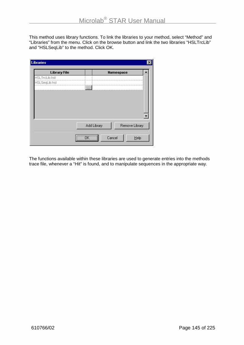
Microlab® STAR User Manual
610766/02 Page 145 of 225
This method uses library functions. To link the libraries to your method, select “Method” and“Libraries” from the menu. Click on the browse button and link the two libraries “HSLTrcLib”and “HSLSeqLib” to the method. Click OK.
The functions available within these libraries are used to generate entries into the methodstrace file, whenever a “Hit” is found, and to manipulate sequences in the appropriate way.

Microlab® STAR User Manual
Page 146 of 225 610766/02
The items of this method in the graphical Method Editor are displayed on the next screen:
�����+�����,�/�.������
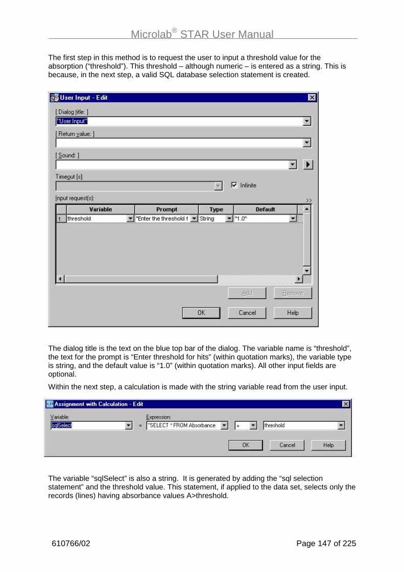
Microlab® STAR User Manual
610766/02 Page 147 of 225
The first step in this method is to request the user to input a threshold value for theabsorption (“threshold”). This threshold – although numeric – is entered as a string. This isbecause, in the next step, a valid SQL database selection statement is created.
The dialog title is the text on the blue top bar of the dialog. The variable name is “threshold”,the text for the prompt is “Enter threshold for hits” (within quotation marks), the variable typeis string, and the default value is “1.0” (within quotation marks). All other input fields areoptional.
Within the next step, a calculation is made with the string variable read from the user input.
The variable “sqlSelect” is also a string. It is generated by adding the “sql selectionstatement” and the threshold value. This statement, if applied to the data set, selects only therecords (lines) having absorbance values A>threshold.

Microlab® STAR User Manual
Page 148 of 225 610766/02
The syntax of the SQL statement is: "SELECT * FROM [absorbance$] WHERE OD > "
Here “absorbance$” refers to the name of the Excel sheet which is going to be openedduring the next steps.
Now, the sequence “Hits” as generated within the sequence editor is reduced to 0 (all entriesare deleted) using a library function call:
The parameter is the sequence ML_STAR.Hits.
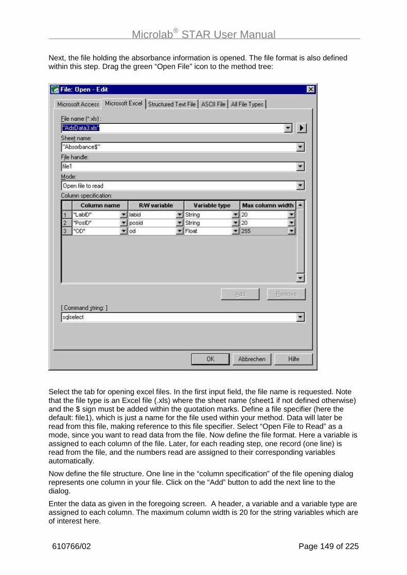
Microlab® STAR User Manual
610766/02 Page 149 of 225
Next, the file holding the absorbance information is opened. The file format is also definedwithin this step. Drag the green “Open File” icon to the method tree:
Select the tab for opening excel files. In the first input field, the file name is requested. Notethat the file type is an Excel file (.xls) where the sheet name (sheet1 if not defined otherwise)and the $ sign must be added within the quotation marks. Define a file specifier (here thedefault: file1), which is just a name for the file used within your method. Data will later beread from this file, making reference to this file specifier. Select “Open File to Read” as amode, since you want to read data from the file. Now define the file format. Here a variable isassigned to each column of the file. Later, for each reading step, one record (one line) isread from the file, and the numbers read are assigned to their corresponding variablesautomatically.
Now define the file structure. One line in the “column specification” of the file opening dialogrepresents one column in your file. Click on the “Add” button to add the next line to thedialog.
Enter the data as given in the foregoing screen. A header, a variable and a variable type areassigned to each column. The maximum column width is 20 for the string variables which areof interest here.

Microlab® STAR User Manual
Page 150 of 225 610766/02
Select the variable “sqlSelect” from the dropdown list as a command string.
Click OK to finish the definition.
A loop is started, looping over the input file (until the file has been read completely):
Within the loop, the first record of the file is read:
Next, using the library function “SeqAdd”, a sequence position is added to the hitsequence. No if-then is needed here, because the SQL selection string automaticallyskips all records with absorption values less than or equal to the value of the“threshold” variable.
Then, an entry is made into the methods trace file (HitPick.trc) using the libraryfunction “TrcTrace8”, to inform the user.

Microlab® STAR User Manual
610766/02 Page 151 of 225
This function adds a text of eight variables to the trace file.
After the file has been analyzed and the Hit sequence has been generated, theloading of the sequences (carriers) to the deck may start. The load SMART Steplooks like this:
���
����%����/��&��������������� $���������������������������������������3!�������������������������������"������������ $�����5��$��� �����������(������������$�������� ��6����.��8&��������������������������%�������������������������
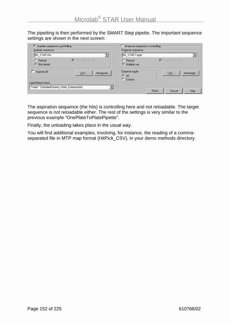
Microlab® STAR User Manual
Page 152 of 225 610766/02
The pipetting is then performed by the SMART Step pipette. The important sequencesettings are shown in the next screen:
The aspiration sequence (the hits) is controlling here and not reloadable. The targetsequence is not reloadable either. The rest of the settings is very similar to theprevious example “OnePlateToPlatePipette”.
Finally, the unloading takes place in the usual way.
You will find additional examples, involving, for instance, the reading of a comma-separated file in MTP map format (HitPick_CSV), in your demo methods directory.

Microlab® STAR User Manual
610766/02 Page 153 of 225
�#�-� ������� �$���/��������� ���7����/����� ����"�����&����!�� ��/����&��"� �!����
The following method transfers liquid from tubes to a plate using steel needles. Theaspirations and dispenses are done with single steps and for the washing of needles theSMART Steps are used. A reduction of the number of samples is possible.
The method uses the following deck layout:
A plate and a set of four tube carriers (of 24 tubes is used). Add the standard plate carrier(PLT_CAR_L5MD). Add a Nunc plate (nun_96_fl_l.rck) and name it “Plate”. as well as thetube carriers (car24_cup15x100.rck) as decribed previously. In addition, a wash station isadded to the rightmost position on the deck. Select the carrier for the wash station“car_wash_1_standardneedle.tml” from the ML_Star directory.
Save the deck layout under the name “TubesToPlateWithNeedles(.lay)”.
Create a sequence holding all tubes called “Samples”, and a second sequence holding allwash modules and name it “WashStations”, using the sequence editor as described in theprevious examples.
Click on Edit Method and link the deck layout to the method to be written.

Microlab® STAR User Manual
Page 154 of 225 610766/02
Here’s what the method finally looks like:
��������������� �.
Load the “Plate” and “Samples” sequences. The “Samples” sequence is reducible (check thecheckbox) to allow a runtime reduction of samples.
Drag the SMART Step “Needle Wash Settings” to the next line, accept the default settingsand click OK. Select the sequence ML_STAR.WashStations.
Drag a loop from the general commands.
Loop over the Samples sequence.

Microlab® STAR User Manual
610766/02 Page 155 of 225
The next step is the “adjust sequences” command. This command is used to automaticallyhandle a reduction of samples when using single steps. If, say, only 4 samples are left overin the last step, “adjust sequences” ensures that the system will pick up only 4 tips, aspirate4 samples, and dispenses into 4 plate positions, leaving the other 4 channels unused.
Multiple sequences may be added to the dialog by clicking on the “Add” button and selectingthe sequence from the dropdown field.
���
+��$��%���������������������� ���������������������6��H����%����8�������&���� ������������%����
����������������6��H����%����8����������������� ����! ������"��������������&��� ������������� ������������ ����
Now, pick up needles using the SMART Step:

Microlab® STAR User Manual
Page 156 of 225 610766/02
Select the sequence ML_STAR.WashStations holding all individual wash modules.Click OK.
Aspirate from the “Samples” sequence and dispense into the “Plate” sequence withthe settings as described in the example “TubesToPLate”.
Eject the needles with the SMART Step:
Again, select the sequence ML_STAR.WashStations and check the checkbox “Startwash”.
The SMART Steps “needle pick up” and “needle eject” will handle the washing withinthe alternating three wash modules automatically.
Finally, the carriers may be unloaded.

Microlab® STAR User Manual
610766/02 Page 157 of 225
�#�B� �� ��������3��&�������$������2��� ����&���7����&������!1��/7���4���!�����&�������7���&�������7��� ���$��
The following example gives an idea of the additional functionality of the MicrolabSTAR user software.
Create the following deck layout holding a tip carrier TIP_CAR_480 with tip racks (atleast two racks), 3 tube carriers (car32_cup12x75.rck) for 32 tubes and atemperature-controlled carrier (car_tcc_1.tml) named “TempCarrier” with a standardnunc plate (nun_96_fl_l.rck), named “plate”.
Save the layout under the name “Example” (do not use a name longer than 20characters including extension).
Create sequences for all tips (“AllTips”) and for all tubes (“AllTubes”), using thesequence editor.
Open the method editor and link the deck layout to the method to be written.
Link the following libraries to the method (method->libraries):

Microlab® STAR User Manual
Page 158 of 225 610766/02
���
�������������������� ������������������������9�6���� ������8����������������������������������������������������������������� �������������9���@3������������� ��������9�������
Finally, the method should look like this, following the first step “Initialize” (the displayof method steps continues overleaf):

Microlab® STAR User Manual
610766/02 Page 159 of 225
������� ������
Firstly, initialize the system and load all carriers using the single steps:

Microlab® STAR User Manual
Page 160 of 225 610766/02
Assign the name of the tip counter (MyStandardTips) to be used throughout this method tothe variable ’TipCounterVariable’ (as a string, i.e. within quotation marks) :
Define a user input request for the temperature of the TCC as well as the number of samplesto be transfered.
For every input, a variable name, a text to prompt for the variable (within quotationmarks), the variable type, and a default value have to be given. Type in the inputsas shown in line 8 of the method overview.

Microlab® STAR User Manual
610766/02 Page 161 of 225
Set the TCC settings according to the following dialog:
The temperature is now set to the variable CTemp, the value of which is to be typedin by the user at runtime.
Now, the tip counting is specified using functions from the tip counter library. First,the user will be requested to reset the tip counter (if required):
The “TipCountingEdit “ function opens up a dialog on runtime, showing the tipsequence and input fields for start and end positions. Setting the start position to 1will reset the tip counter - then tips have to be reloaded manually. This function hasparameters: the tip sequence, the name of the tip counter (which is stored in
the variable “TipCounterVariable” here), the device context (select the only choice“ML_STAR” from the dropdown field), and a timeout. This timeout is used to close the
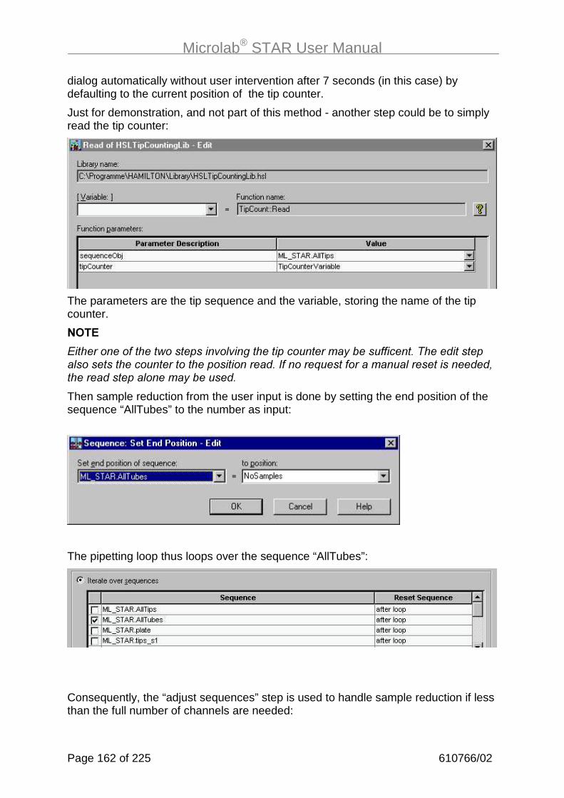
Microlab® STAR User Manual
Page 162 of 225 610766/02
dialog automatically without user intervention after 7 seconds (in this case) bydefaulting to the current position of the tip counter.
Just for demonstration, and not part of this method - another step could be to simplyread the tip counter:
The parameters are the tip sequence and the variable, storing the name of the tipcounter.
���
+����������������������� ������������������$��������������������� �������������������������������(������%�������������� ����������&���������� �����$�������
Then sample reduction from the user input is done by setting the end position of thesequence “AllTubes” to the number as input:
The pipetting loop thus loops over the sequence “AllTubes”:
Consequently, the “adjust sequences” step is used to handle sample reduction if lessthan the full number of channels are needed:

Microlab® STAR User Manual
610766/02 Page 163 of 225
Add all the sequences shown in the dialog, and recall the notes in the previouschapter.
For the pipetting (single) steps, the settings are as in the other examples:
Tip Pick-up: Sequence “AllTips”, counting automatic
Aspiration: Sequence “AllTubes”, counting automatic
Dispense: Sequence “plate”, counting automatic
Then, the current position of the tip sequence is written into the tip counter:
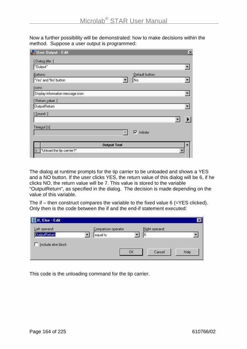
Microlab® STAR User Manual
Page 164 of 225 610766/02
Now a further possibility will be demonstrated: how to make decisions within themethod. Suppose a user output is programmed:
The dialog at runtime prompts for the tip carrier to be unloaded and shows a YESand a NO button. If the user clicks YES, the return value of this dialog will be 6, if heclicks NO, the return value will be 7. This value is stored to the variable“OutputReturn”, as specified in the dialog. The decision is made depending on thevalue of this variable.
The if – then construct compares the variable to the fixed value 6 (=YES clicked).Only then is the code between the if and the end-if statement executed:
This code is the unloading command for the tip carrier.
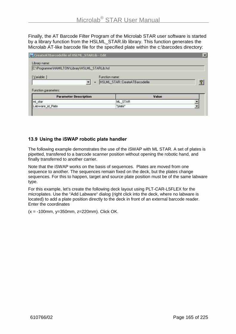
Microlab® STAR User Manual
610766/02 Page 165 of 225
Finally, the AT Barcode Filter Program of the Microlab STAR user software is startedby a library function from the HSLML_STAR.lib library. This function generates theMicrolab AT-like barcode file for the specified plate within the c:\barcodes directory:
�#�;�$���/�������,�)�������!�&�������� ���
The following example demonstrates the use of the iSWAP with ML STAR. A set of plates ispipetted, transfered to a barcode scanner position without opening the robotic hand, andfinally transferred to another carrier.
Note that the iSWAP works on the basis of sequences. Plates are moved from onesequence to another. The sequences remain fixed on the deck, but the plates changesequences. For this to happen, target and source plate position must be of the same labwaretype.
For this example, let’s create the following deck layout using PLT-CAR-L5FLEX for themicroplates. Use the “Add Labware“ dialog (right click into the deck, where no labware islocated) to add a plate position directly to the deck in front of an external barcode reader.Enter the coordinates
(x = -100mm, y=350mm, z=220mm). Click OK.

Microlab® STAR User Manual
Page 166 of 225 610766/02
Create independent sequences for pipetting steps and transport steps, using the sequenceeditor. Both the transport and pipetting sequences span all 3 plates. The first step of themethod is a simple aliquot step to transfer reagent to the plates, located at plate carrier 1using the SMART Step “Pipette“.

Microlab® STAR User Manual
610766/02 Page 167 of 225
Then, we loop over the transport sequence “TransportSequencePlate1To“ spanning allplates on the left-hand plate carrier. At the beginning of the method, the plates are located onthis plate carrier. In step 3 we pick up the plate from the current sequence position ofsequence “TransportSequencePlate1To“:
The “Movement Type“gives 2 options: either to pick up the plate from a carrier, which is asimple motion, or to pick up a plate from a reader, etc., which is a complex motion. For acomplex motion additional inputs can be made, such as the “retract distance“ and the “lift-upheight“ (see online help).
“Transport mode“ specifies whether the plate is to be picked up - with or without a lid - or justthe lid itself.

Microlab® STAR User Manual
Page 168 of 225 610766/02
Sequence counting again determines whether the iSWAP returns to the same or to the nextplate of the given sequence next time.
Note that a plate lid by itself has a sequence with 2 positions. Selecting the transport mode“Plate with Lid“ will increment the plate as well as the lid sequence.
Under “Advanced“, additional settings may be chosen:
“Grip force“ determines the force that is used to grip the plate. The tolerance gives abandwidth in mm for the closing mechanism of the robotic hand in which the plate must begripped (torque sensor of iSWAP responds). The grip height is the distance that iSWAPmoves down from the plate’s upper rim to grip the plate. Inverse grip instructs the robotichand to pick up a plate with the opposite orientation of the iSWAP (this is not alwayspossible).
The plate is now moved to the position of the barcode scanner (the position of the sequence“PlateAtExternalBCScanner“), without opening the hand:
The final step places the plate on the right-hand plate carrier:

Microlab® STAR User Manual
610766/02 Page 169 of 225
�%���� ��/�������!���������"
�%��� �����������
To load the Microlab STAR, first load the carriers with the appropriate labware.
.1) If you have incorporated Q��� ������R commands into your method, you can start therun and the instrument will prompt you to load the carriers manually onto the deck. Makesure the carriers are inserted completely, until they lock into the rear connectors. A magneticdetector checks whether your loading of carriers is correct.
.2) If you have ���Q��� ������R commands incorporated into your method, you must loadthe carriers manually into the positions on the deck defined in the deck layout ������ the runis started. Make sure that the carriers are inserted completely, until they touch the rearconnectors.
���
(����� ����������������������������������������&������������������������������������ ��������������
Magnetic Sensor

Microlab® STAR User Manual
Page 170 of 225 610766/02
� �����
When using the Autoload option, first load the carriers with the appropriate labware.
.1) If you have incorporated Q��� ������R commands into your method: start the “RunScreen” as described in the following sections, and run the method. The correct positions forthe insertion of carriers will be highlighted by the green LEDs. Insert the carriers into thetracks of the Autoload tray until they touch the holding pins on the far side of the tray.
Click “Load” in the dialog, and the carriers are loaded onto the deck automatically by the“load carrier” command in the method. At the same time, the barcodes of carriers andlabware are read and stored in a file.
Alternatively, load the carriers on to the defined positions of the autoload tray before startingthe method. Loading and barcode reading will then be performed without user input.
.2) To repeat what we said already: if you have no ‘LoadCarrier’ commands incorporated intoyour method, you must load the carriers manually into the positions on the deck defined inthe deck layout before the run is started. Make sure that the carriers are inserted completely,until they touch the rear connectors.
���
(����� ����������������������������������������&������������������������������������ ��������������
Holder for Carrier

Microlab® STAR User Manual
610766/02 Page 171 of 225
�'��"�����/�������!���������"
�'���"�����/������&�������� �:������������������
To run the method “OnePlateToPlatePipette” from the example section, you need to accessthe run control. Double-click the “Microlab STAR Run” short cut on the desk top:
From the File menu of Run Control, select Open, and open the deck layout that was createdfor the method “OnePlateToPlatePipette” (directory ...\methods\DemoMethods_MLStar).Your method is now loaded:
��������:���� �������
The relevant deck layout appears in the frame in the upper half of the window. The lowerhalf contains the Start button and another blank frame which will display the run method log(method trace file) as it generates.
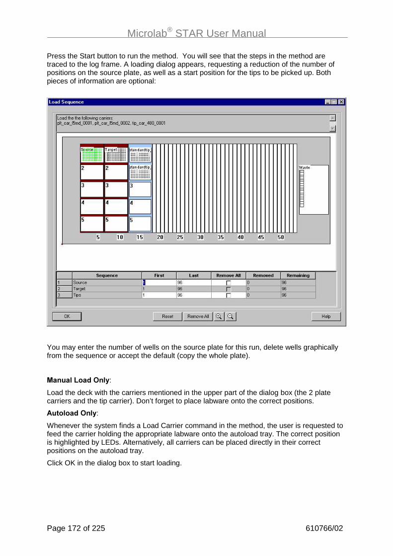
Microlab® STAR User Manual
Page 172 of 225 610766/02
Press the Start button to run the method. You will see that the steps in the method aretraced to the log frame. A loading dialog appears, requesting a reduction of the number ofpositions on the source plate, as well as a start position for the tips to be picked up. Bothpieces of information are optional:
You may enter the number of wells on the source plate for this run, delete wells graphicallyfrom the sequence or accept the default (copy the whole plate).
���������� ����(:
Load the deck with the carriers mentioned in the upper part of the dialog box (the 2 platecarriers and the tip carrier). Don’t forget to place labware onto the correct positions.
������� ����(:
Whenever the system finds a Load Carrier command in the method, the user is requested tofeed the carrier holding the appropriate labware onto the autoload tray. The correct positionis highlighted by LEDs. Alternatively, all carriers can be placed directly in their correctpositions on the autoload tray.
Click OK in the dialog box to start loading.

Microlab® STAR User Manual
610766/02 Page 173 of 225
At the end of the method, you are requested to unload the carriers from the deck. Thefollowing dialog box opens:
���������� ����(=
Click OK within the dialog. Unload all the carriers manually. The unloading will be checked bythe system.
������� ����(=
Click OK within the dialog. The carriers are unloaded to the autoload tray.
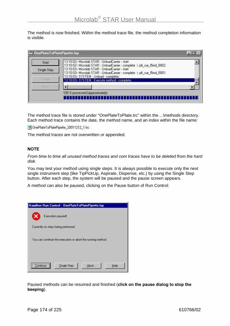
Microlab® STAR User Manual
Page 174 of 225 610766/02
The method is now finished. Within the method trace file, the method completion informationis visible.
The method trace file is stored under “OnePlateToPlate.trc” within the ...\methods directory.Each method trace contains the date, the method name, and an index within the file name:
The method traces are not overwritten or appended.
���
-������������� ��������������������������������������� ������������������
You may test your method using single steps. It is always possible to execute only the nextsingle instrument step (like TipPickUp, Aspirate, Dispense, etc.) by using the Single Stepbutton. After each step, the system will be paused and the pause screen appears.
A method can also be paused, clicking on the Pause button of Run Control:
Paused methods can be resumed and finished (!��!1��������&����� ����/�������&�������&��/).
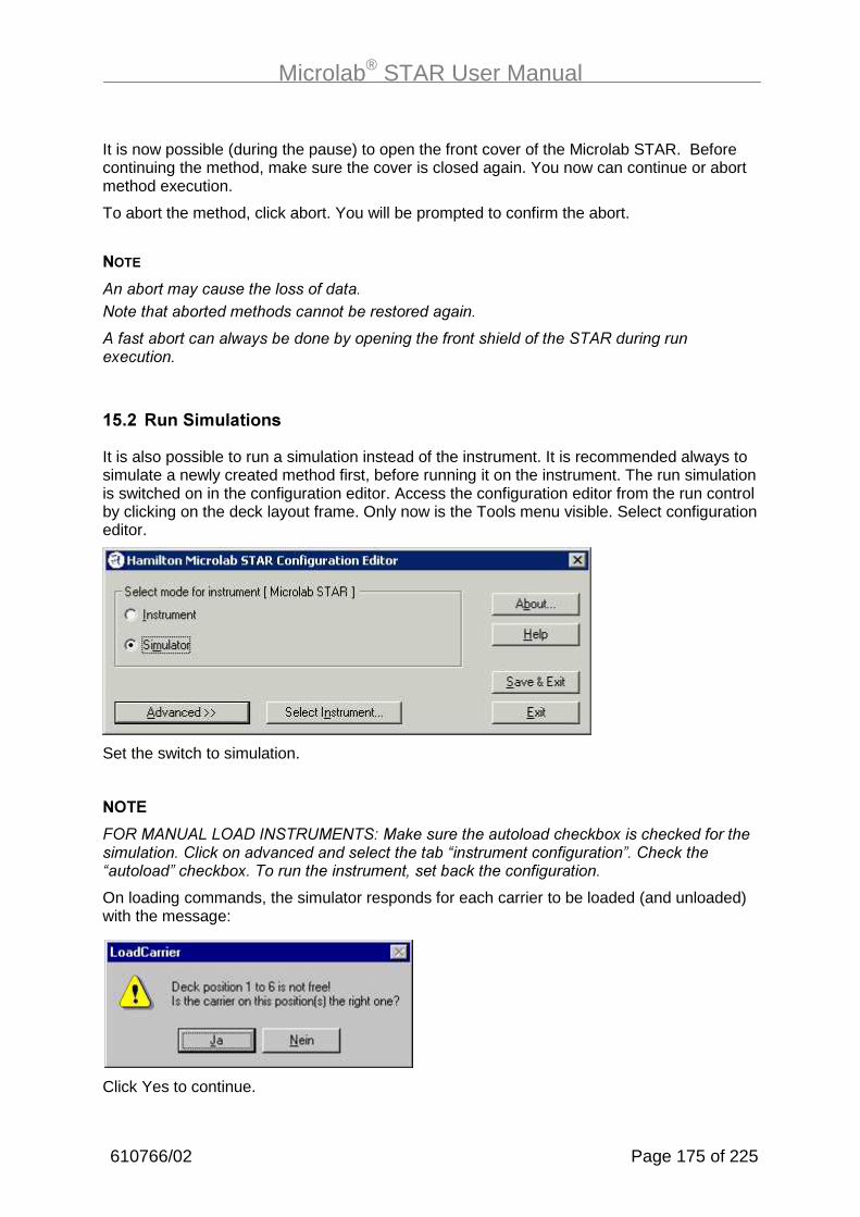
Microlab® STAR User Manual
610766/02 Page 175 of 225
It is now possible (during the pause) to open the front cover of the Microlab STAR. Beforecontinuing the method, make sure the cover is closed again. You now can continue or abortmethod execution.
To abort the method, click abort. You will be prompted to confirm the abort.
���
����������$�������� �����������#�������������������������������������
���������������� ��$���������$������������������ ����������������������9������
�'���"��������������
It is also possible to run a simulation instead of the instrument. It is recommended always tosimulate a newly created method first, before running it on the instrument. The run simulationis switched on in the configuration editor. Access the configuration editor from the run controlby clicking on the deck layout frame. Only now is the Tools menu visible. Select configurationeditor.
Set the switch to simulation.
���
-*����#��)�)*���(#�����+#��,�������������� ����������9������������������� ������: �������������������� �������6��������������������8��:�����6��� ���8�������9������������������&�����������������������
On loading commands, the simulator responds for each carrier to be loaded (and unloaded)with the message:
Click Yes to continue.

Microlab® STAR User Manual
Page 176 of 225 610766/02
�'�#�"�������������8�� ���/
Prior to runtime error handling being used, several types of problems causing errors have tobe solved first. Among these are
- Syntax errors when programming in HSL (forgotten “;”)
- Logical errors (tip eject before pick up, asp 10ul, disp 200ul)
- Semantic errors (wrong pipetting pattern)
- Method/deck interaction errors (dispense 100 µl into the first well of a 1536-well MTP)
- Liquid handling/application errors (droplets, foam, unpipetted wells)
- User-related errors (sample tubes not filled completely, wrong deck loading, barcodesunreadable)
These problems !������be handled by any runtime error handling.
Problems that can be handled in runtime are
- Not enough liquid
- liquid level not found (if it occurs only rarely)
- No tip picked up
- Clot detected
- Barcode unreadable (if it occurs only rarely)
- Execution error (channel no. 1 has an error (e.g., not enough liquid), then channel nos. 2-8 have an execution error because they have been stopped before completion of thestep)
���
(��������� &���������� ���$����������������������$�������������������
(��� ������ ���������������������������&����� ��������$�����������
We now focus on some important examples. A detailed description is available in the onlinehelp. Click on Error Settings within the single step dialogs of the Microlab STAR-specificcommands.
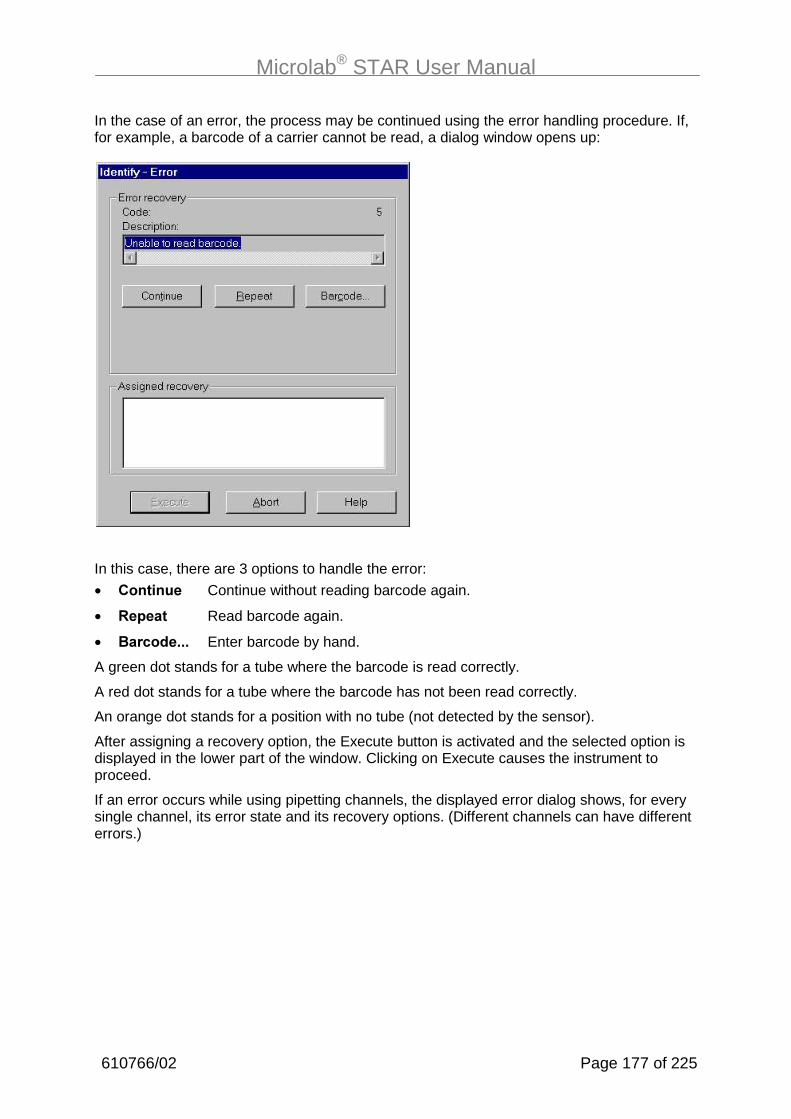
Microlab® STAR User Manual
610766/02 Page 177 of 225
In the case of an error, the process may be continued using the error handling procedure. If,for example, a barcode of a carrier cannot be read, a dialog window opens up:
In this case, there are 3 options to handle the error:
• ������� Continue without reading barcode again.
• "�&��� Read barcode again.
• ���!� ���� Enter barcode by hand.
A green dot stands for a tube where the barcode is read correctly.
A red dot stands for a tube where the barcode has not been read correctly.
An orange dot stands for a position with no tube (not detected by the sensor).
After assigning a recovery option, the Execute button is activated and the selected option isdisplayed in the lower part of the window. Clicking on Execute causes the instrument toproceed.
If an error occurs while using pipetting channels, the displayed error dialog shows, for everysingle channel, its error state and its recovery options. (Different channels can have differenterrors.)

Microlab® STAR User Manual
Page 178 of 225 610766/02
For example, in case of an LLD error such as no liquid in the container while aspirating, awindow similar to the following pops up:
Red-coloured channel 1 and channel 2 failed to aspirate. To each of these two channels arecovery option has to be assigned. Only if all channels have the same error is the chosenrecovery option assigned to all channels simultaneously.
Selecting channel 1 shows the error description and the available recovery options for thischannel (buttons Exclude, Repeat, etc.). Invoke one of these options by clicking theappropriate button. Your selection is displayed in the lower part of the window.
In this case, there are 5 options to handle the error:
• �3!�� � The channel is excluded (no more aspirate, dispense, etc. with thischannel) until next TipPickUp.
• "�&��� Repeat aspirate command.
• ������ Aspirate from bottom of container, without LLD.
• ��� Aspirate air.
• ��.��$& Channel is moved up to dispense liquid into the container. After this action,aspiration can be repeated.
Note that the Continue button is disabled. This prevents any later dispense with insufficientvolume.
Repeat the same procedure for channel 2. Note that the error and the associated recoveryoptions may differ from those for channel 1.
When the last channel is processed, the Execute button becomes active and the system canproceed.
In any case the method can be aborted without further recovery options.

Microlab® STAR User Manual
610766/02 Page 179 of 225
�'�%�,��12�:�(�I)�� ����� J�������8�� ���/
The user may define a walk-away error handling which uses predefined default settings fordifferent error situations. These settings can be customized for single steps only. For SMARTsteps, the default error recovery is fixed.
For every instrument-specific single step of your method, an individual error recovery can bedefined. You can configure
- the appearance of the error recovery dialogs (which buttons are available)
- the default procedure
- which error is flagged in the trace file
- a timeout, after which the default recovery is carried out (the dialog automatically closesdown).
For this purpose, every instrument-specific single step has a “Error Settings” button. For theaspiration step, it looks like this:
Among these various tabs, we have selected “Liquid Level Error”. The default settings areactivated.

Microlab® STAR User Manual
Page 180 of 225 610766/02
To customize the settings, disable the “Use Default” checkbox. A brief description of the erroris given, followed by the available recovery options. Only one default procedure can beselected. Among the choices are:
- Cancel (quits the current step and starts the user defined error handling, if specified. If nouser defined error handling is present, the method aborts).
- Abort (aborts the method).
- Bottom
- Exclude
- Repeat
- Air
The flag “visible” allows you to add the appropriate button to the error recovery dialog box.The flag “flag” allows you to flag the error to the trace file.

Microlab® STAR User Manual
610766/02 Page 181 of 225
To enable walk-away handling of errors, disable the checkbox “infinite” and enter a timeoutinto the input field. The runtime error dialog then pops up, waits for the timeout, and closes tocontinue with the default error recovery chosen for this error.
If the user clicks on the error dialog during the timeout, the walk away will be stopped, andthe user has to select a recovery and continue manually.
For a list of all errors and their recovery options, refer to the online help and the error settingsdialogs. However, the most important errors are the ones listed in the foregoing chapter.

Microlab® STAR User Manual
Page 182 of 225 610766/02
�+�������!������������!� �������������
Along with the software comes a filter tool to generate a Microlab AT-like barcode file. Thisfilter can be started manually, or from the shell command of a method (see example). Thesample tracking works as follows:
- Check the check box “sample tracking” in the configuration editor.
- At runtime, one Access-based data base (*.mdb) will be generated within the ...\logfilesdirectory, storing all liquid transfers of one method.
- An additional register file HxRunIndex.mdb stores information about all runs performed.
- After the method (or at least the liquid transfers) are finished, the filter tool can be calledto generate the Microlab AT-like barcode file from the data base. The filter tool is storedunder ...\hamilton\bin.
���
�������������� ���� &�������������������9���@3������������� �����9�������
���� ����������������������������9���@3����������
Given that a method has been run with the sample tracking enabled and a 96-well plate hasbeen prepared, the directory c:\barcodes now contains (at least) one barcode file(At_barco.nij) plus the two register files, containing information about all runs performed sofar (for a description of *.reg files refer to the Microlab AT user manual):
The barcode files can be directly used to couple the Microlab STAR and Microlab FAME.
Now, start the filter tool manually, by selecting
START->Programs->Hamilton->Micolab STAR->AT Barcode Filter
Click on the icon:

Microlab® STAR User Manual
610766/02 Page 183 of 225
A window opens up showing the available runs:
Select a run in the upper half to get a list of labware, processed during the run. Double-clickon the plate for which a barcode file is to be generated. Another window opens up, displayinga table with the pipetting information of the plate in a convenient form:
The table may be printed from the menu.
To start the AT Filter automatically at the end of a method, see the example in chapter 13.7.

Microlab® STAR User Manual
Page 184 of 225 610766/02
�-��"������!�� �� �=�0������/����:���
�-��� �������:����� ����
If your labware is not pre-defined, you can define custom racks and containers using thelabware editor. Such custom labware can be used like any other pre-defined labware objectfrom the library. The idea is that the labware object is a description of the real physicallabware.
To start the Labware editor from the deck editor:
1. select ’Add Labware’ from the ’Edit’ menu or from the popup menu and click the ’Lab.Editor’ button, or
2. select the Labware Editor from the ’Tool’ menu, or
3. simply click on the ’Define Labware’ icon under on the tool bar.
If you want to add the new labware directly after definition, choose the first procedure.
Whatever you choose, the labware editor starts with the following main window:
�-��� �(&���������:���
�-����� "�!���/�����"�!1���� �)�����
Rectangular racks are specialized grids for holding either tips or containers in row andcolumn order. A microtiter plate is a rack in this sense, and the wells represent thecontainers. The rack is therefore a template describing a discrete number of positions forholding containers or tips. Examples of racks include a tube rack, a microtiter plate, amicrotiter strip, a deep-well plate, and a tip rack.
The filename has the extension “.rck”.

Microlab® STAR User Manual
610766/02 Page 185 of 225
���
��� ������ ��� ����� �����&� � ��$�� ��� �� 6������ ��� ����8� ���� not� �� 6������ �8����������������� �����������
�-����� ���������
Containers are vessels holding liquids (e.g., the wells of a microtiter plate). Containers areusually placed within racks. Containers may be placed directly onto the carriers, which is thecase e.g. with reagent containers.
The filename has the extension “.ctr”.
���
:* �+����������� ������ ���������������������
�-���#� ��!�����"�!1�
Circular racks are specialized grids for holding either CO-RE tips or containers in a segmentof a circle.
The filename has the extension “.crk”.
�-�#� �3��&��=�0������/���"�!���/�����"�!1�:�������������
The following sections illustrate the procedures for defining labware using the example of arectangular custom rack and containers.
�-�#��� 0������/�����������
Let’s define a new container. At the end of the container definition we can use that containerin a rack definition.
To start:
1. from the labware editor select 'New' and then 'Container' out of the 'File' menu, or
2. in the Rack definition dialog press the 'New' button.

Microlab® STAR User Manual
Page 186 of 225 610766/02
In both cases the following dialog box is shown:
We define the containers as round-bottomed tubes of diameter 10 mm, with a total length of75 mm. Indicate the number of container segments (here 2, because our tube has acylindrical and a round-bottomed part) and the clearance height (here 80 mm) at which thepipetting arm can pass over the container without touching it, as measured from thecontainer base. The maximum pipetting height counted from the container bottom is 4 mm,because we want to allow the tip to go down to a position of 4 mm above the tube bottom(this gives the “dead” volume).
The touch-off height means the position of the tip when dispensing with “touch off” into anempty container. It is set to 0.3 mm although this option is not available for all instruments(including the ML-STAR) at the present time. The same is true for the “wick side of container”checkbox, which in principle enables or disables touch-off at the sides of the containers but isalso not available for all instruments.
The next important option is the “Liquid Level Valid” checkbox, which is activated here, andthe value of 75 mm above the tube bottom to start the liquid level detection within the tube.
The 'Thickness of Container base' is used to place a rack filled with such containers in thecorrect Z position.
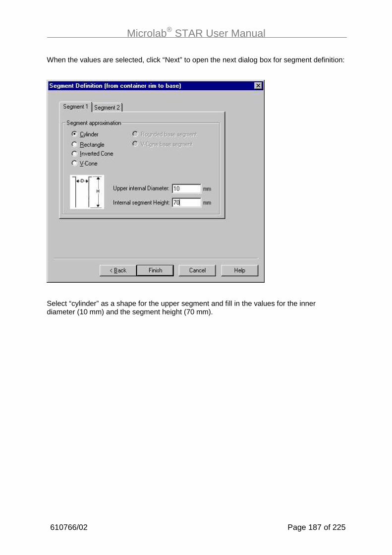
Microlab® STAR User Manual
610766/02 Page 187 of 225
When the values are selected, click “Next” to open the next dialog box for segment definition:
Select “cylinder” as a shape for the upper segment and fill in the values for the innerdiameter (10 mm) and the segment height (70 mm).
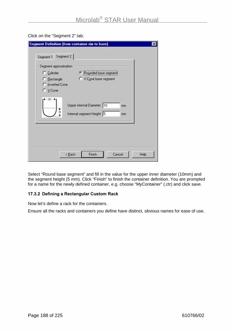
Microlab® STAR User Manual
Page 188 of 225 610766/02
Click on the “Segment 2” tab.
Select “Round base segment” and fill in the value for the upper inner diameter (10mm) andthe segment height (5 mm). Click “Finish” to finish the container definition. You are promptedfor a name for the newly defined container, e.g. choose “MyContainer” (.ctr) and click save.
�-�#��� 0������/���"�!���/�����������"�!1
Now let’s define a rack for the containers.
Ensure all the racks and containers you define have distinct, obvious names for ease of use.

Microlab® STAR User Manual
610766/02 Page 189 of 225
Select “New” and “Rectangular Rack” from the File menu of the main window. A series ofquery dialog windows starts, giving the user the opportunity to design the rack.
Choose always “Rectangular Rack” to define or modify rectangular racks and microplates.Choosing “microtiter plate” requests only a subset of the information relevant for the ML-STAR. Click “Next”.
Specify the number of rows (here 2), the number of holes per row (here 4), and the innerdiameter of the hole (here 12 mm) which will later receive the container. Check “Load Rackwith Containers” and give the overall clearance height of the assembly (here 100 mm). Alsocheck “Include Rack Boundary” to allow the boundaries to be set in the next steps. Accept

Microlab® STAR User Manual
Page 190 of 225 610766/02
the default for “Stagger” (an option allowing you to shift the rows with respect to each other)and click “Next”.
The next dialog appears:
Specify the distance between the holes in a row (here 20 mm) and the distance between therows (here 30 mm). Click “Next”.

Microlab® STAR User Manual
610766/02 Page 191 of 225
Accept the defaults for the indexing of the holes, for alpha-numeric indices ranging from A1to H12, and click “Next”.
Type in the width and length of the rack (here, e.g. the outline of a microplate) and the rackboundaries. Click “Next”.

Microlab® STAR User Manual
Page 192 of 225 610766/02
See section 17.5 for more information on these inputs.
Now the rack definition is finished. Since we checked “Load the Rack with Containers” in thesecond screen, we now have to define the containers which will be placed in the holes of therack.
We have the choice either to browse the directories for defined containers (extension “.ctr”)to fill our new rack with, or to define a new container.
We now come to the end of rack definition, with the new container pre-selected.
Accept the defaults and click “Finish” to finish the rack definition.

Microlab® STAR User Manual
610766/02 Page 193 of 225
You now see your newly defined rack in the Labware Editor:
Choose Save in the File menu to store the new rack under the name “MyRack” (.rck) in thelabware directory. Select Exit from the File menu.
Once you are back in the “Add Labware” or in the "Deck Layout editor" window, you can putthe newly-designed rack on the deck: under Type select “MyRack.rck”, and the new rack isvisible in the “add Labware” Window.
�-�#�#� 0������/����������I���&����J
Carriers are also pieces of labware. Carriers have sites to host racks such as microplates.Let us now define a carrier, preloaded with flat 96 well nunc microplates.
���
��6���������8������������� ��������������������������������!���� �"��(����������&������� $����������������$����������� ���������������������������� $ ������������������������

Microlab® STAR User Manual
Page 194 of 225 610766/02
To define a carrier, open the labware editor and select New->Template. A window pops up:
The width of the carrier is given by
width/mm=“number of tracks” x 22.5 mm/track
In the case of a plate carrier which is 6 tracks wide, the result is 136mm. The length of aMicrolab STAR track is 497 mm. The clearance height for all carriers on the instrument is136 mm.
Select the “Preloaded” check box to let the carrier be preloaded with the microplates. Selecta colour of your choice. Click Continue.

Microlab® STAR User Manual
610766/02 Page 195 of 225
Within the next window, the sites hosting the plates have to be defined:
Click on the Add button and double-click the added line.
The drawing on the right illustrates the different coordinates. The values refer to a standardmicroplate. Drawing is only of “optical” influence; accept the defaults. For “Snap to site”,select the lower option for a microplate, because a microplate fits with its bottom on to theplate carrier (to enable a good electrical coupling for capacitance-based LLD).
The decision whether a plate (or tip rack) fits on to a site of a carrier is made depending onthe width and legnth of the site: all plates that have the same boundary measures (width andlength) can be placed on the site.
Different plate types (96 flat and deep well, 1536 well, etc.) have the same boundarymeasures.
������������������������������&����
����
↑ length
↓
↔ width
origin x
origin y

Microlab® STAR User Manual
Page 196 of 225 610766/02
You may add additional sites to the same carrier. Click next. Now, the site can be preloaded:
Click on Browse, to browse for the corresponding labware and click Add, to add the selectedlabware to the site. Click Finish. Save the new carrier within the labware editor.
Now open the deck editor and place the carrier onto the deck:
The carrier is now preloaded with a plate on its site.

Microlab® STAR User Manual
610766/02 Page 197 of 225
Furthermore, a carrier has several properties, such as barcode positions, which may bespecified. To do so, open your newly defined carrier in the labware editor and selectEdit>Properties. A dialog opens up. Here, we open a standard plate carrier:
.������������.)�;:��;)>���
Entries can be added by clicking on Add. The entry names are to be kept; they roughlyexplain the property (see chapter 17.4).
Add the entries and click OK to store them along with the carrier.
���
� ��$�������������������������������������������������� $������������$��������������������������$���������������� ����������������� ������$��������� ��

Microlab® STAR User Manual
Page 198 of 225 610766/02
�-�%� �(��������/���������:����)��&������
Within the labware, some flags and settings (labware properties) are defined to determinehandling of the labware elements. These properties should not be changed by the user. Theyare accessible just so that you can have the maximum of decision-making power in particularsituations that call for it.
These properties can be divided up into the following groups:
• Information for the handling of the auto load unit
• Information for the special units like wash carrier, TTC, tips and needle handling, waste,etc.
• Information to support the reduction of selection during edit time
�-�%��� ����!����
The properties are always combine a key name and a value. The key names are casesensitive (the distinction between capital and lower case is important).
All values are in integers (no decimal points).
�-�%��� ����������������8�� ���/������������� �$���
S�( 0������ "��/� 0��!��&����
MlStarCarWidthAsT - 1 .. (n) Width of carrier in T
MlStarCarCountOfBCPos - 0 .. (n) Count of carrier barcode position
How many barcodes positions areexpected.
MlStarCarRasterWidth - 0.1 mm Distance middle of barcode positionto middle of next barcode position.
MlStarCarBCOrientation 0 0 or 1 0 = Vertical,
1 = Horizontal barcode read direction.
MlStarCarFirstBCPos - 0.1 mm Distance between rear of carrier tomiddle of first barcode position.
MlStarCarBCReadWidth - 0.1 mm Width of barcode read window
MlStarCarIsRecognizable 0 0 or 1 The carrier has a magnetic bar so itspresence can be detected.
1 = TRUE,
0 = FALSE
MlStarCarIsLoadable 0 0 or 1 The carrier can be loaded andunloaded. (A wash station, forexample, is not loadable)
1 = TRUE,
0 = FALSE

Microlab® STAR User Manual
610766/02 Page 199 of 225
S�( 0������ "��/� 0��!��&����
MlStarCarIsAutoLoad 0 0 or 1 The carrier can be loaded andunloaded by the autoload.
1 = TRUE,
0 = FALSE
MlStarCarPosAreRecognizable 0 0 or 1 The presence of the elements loadedon the carrier is detected. (e.g. thecontainers on a sample carrier aredetectable)
1 = TRUE,
0 = FALSE
MlStarCarNoReadBarcode 0 0 or 1 1 = Don’t read barcode,
0 = read barcode
Notes:
• The position of the carrier barcode is not defined in the properties because this position isfixed.
• The barcode positions are ordered at regular intervals (one measurement for one carrier).
• On a carrier, all barcodes must have the same orientation, except the carrier barcode(one value for one carrier)
• The barcode read window is the same for all positions on a carrier. One window shouldnot overlap the next window, otherwise in some cases the barcode cannot be assigned tothe correct position.
• If a carrier is loadable with auto load (MlStarCarIsAutoLoad), the loadable property(MlStarCarIsLoadable) value must be set too.
• At edit time in the load step, the user can only select carriers (templates) with underlyingcarriers having the property “MlStarCarIsAutoLoad”.
• At runtime, if “MlStarCarIsLoadable” and “MlStarCarIsAutoLoad” are not set, no load isrequired; the carriers are fixed on deck or already loaded. If “MlStarCarIsLoadable” is set,a load dialog is shown, and if “MlStarCarIsAutoLoad” is set, loading is executed by theinstrument.
�-�%�#� �����������������&�!����$����
Properties for “calibrate carrier” single command (Carrier 1536):
S�( 0������ "��/� 0��!��&����
MlStarCarCalibrateX - 0.1 mm Distance between left margin ofcarrier to middle of measuring hole.
MlStarCarCalibrateY - 0.1 mm Distance between carrier front tomiddle of measuring hole.
MlStarCarCalibrateZ - 0.1 mm Distance from deck to carrier top

Microlab® STAR User Manual
Page 200 of 225 610766/02
���
(������������������� �����&�� ��� ������� ������
���������������?��������������������!����&� �&�����"
(��������������������� �����&�����$�������� ������� �������9��� �������$�
��������������� �������&������������� $�� ����������!�� ��"��������� $�����������������������������
Properties for Temperature-Controlled Carrier (TCC):
S�( 0������ "��/� 0��!��&����
MlStarCarIsTemperated 0 0 or 1 The carrier can be temperature-controlled
1 = TRUE,
0 = FALSE
MlStarCarIncubatorNumber - 1 or 2 Number of temperature incubationstations 1 or 2
���
��������� $�����::��� �������������
+�����::���������������%�������$���������
������������������������&������������� $�� ���%������������� ������%������������� $����������������������������
Properties for tip and needle handling:
S�( 0������ "��/� 0��!��&����
MlStarIsWasteRack 0 0 or 1 Into this rack tips or needles can beejected
1 = TRUE, 0 = FALSE
MlStarTipRack 0 0..8 0 = Standard Vol Tip disposable
1 = Standard Vol Tip disposable withfilter
2 = Low Vol Tip disposable
3 = Low Vol Tip disposable with filter
4 = High Vol Tip disposable
5 = High Vol Tip disposable with filter
6 = Low Vol Steel Needle
7 = Standard Vol Steel Needle
8 = High Vol Steel Needle
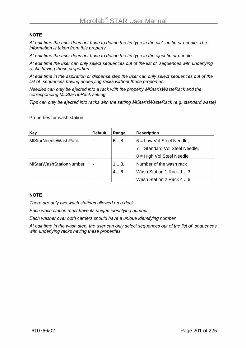
Microlab® STAR User Manual
610766/02 Page 201 of 225
���
�������������������������������������$����������� ����������� ������������������������������������$�
�������������������������������������$�������H���������� �
�������������������� $�� ���%������������� ��������%������������� $���������������������������
������������������������������������������������ $�� ���%������������ ��������%���������������� $���������������������������
#� �������� $���H�������������������������$�� ���(����������������������������)����������������
����������� $���H������������������������� ���(���������!���������������"
Properties for wash station:
S�( 0������ "��/� 0��!��&����
MlStarNeedleWashRack - 6 .. 8 6 = Low Vol Steel Needle,
7 = Standard Vol Steel Needle,
8 = High Vol Steel Needle
MlStarWashStationNumber - 1 .. 3,
4 .. 6
Number of the wash rack
Wash Station 1 Rack 1 .. 3
Wash Station 2 Rack 4 .. 6
���
��������� $����������������� �������������
+�����������������������������%�������$���������
+������������������������������ �����������%�������$���������
��������������������&������������� $�� ���%������������� ��������%������������ $����������������������������
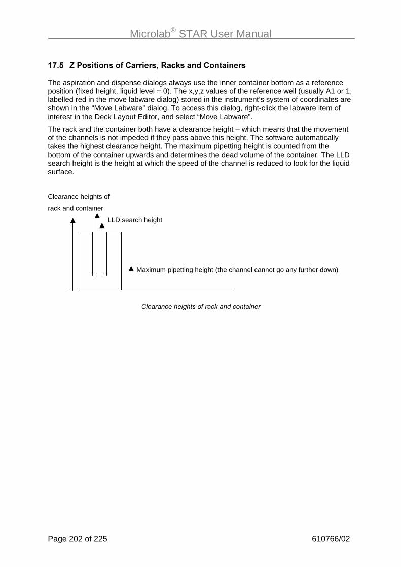
Microlab® STAR User Manual
Page 202 of 225 610766/02
�-�'� �F�)�������������������7�"�!1���� ����������
The aspiration and dispense dialogs always use the inner container bottom as a referenceposition (fixed height, liquid level = 0). The x,y,z values of the reference well (usually A1 or 1,labelled red in the move labware dialog) stored in the instrument’s system of coordinates areshown in the “Move Labware” dialog. To access this dialog, right-click the labware item ofinterest in the Deck Layout Editor, and select “Move Labware”.
The rack and the container both have a clearance height – which means that the movementof the channels is not impeded if they pass above this height. The software automaticallytakes the highest clearance height. The maximum pipetting height is counted from thebottom of the container upwards and determines the dead volume of the container. The LLDsearch height is the height at which the speed of the channel is reduced to look for the liquidsurface.
Clearance heights of
rack and container
LLD search height
Maximum pipetting height (the channel cannot go any further down)
: �������������������������������

Microlab® STAR User Manual
610766/02 Page 203 of 225
Regarding the *�&�������, two different cases of rack placement on the deck can bedistinguished in the Microlab Star:
1. A G!��������2���� H���!1 is placed with the container bottom directly on the carrier(e.g. the microplates on a plate carrier):
Zthick = thickness of container bottom
Zcarrier
Zdeck = 100mm
The reference position Z0 is marked with the *. Here, the reference height is calculated from
Z0 = Zdeck+Zcarrier+Zthick ,
ignoring all other terms. Zdeck is a fixed quantity, Zthick is defined in the labware, and Zcarrier
is defined in the carrier template definition.
2. A G��!12���� H���!1 is placed with the frame on the instrument deck (e.g., a tuberack, where Zcarrier = 0, because the tube rack is used directly as a carrier)
The reference position Z0 is marked with the *. Here, the reference height is calculated from
Z0 = Zdeck+Zcarrier+Zbasediff+Zthick .
Again, Zdeck is a fixed quantity, Zthick and Zbasediff are defined in the labware, and Zcarrier isdefined in the carrier definition. Note that here we have one more term in the equation,compared to the previous case.
Selection between the two types of racks (container-based rack or rack-based rack), andthus the decision which formula is used to calculate the reference z-height from the labwaredata, is done automatically by selecting the hidden grid for the rack. Thus the question ariseshow to define the hidden grid for a rack, i.e., how to define which hidden grid or carrier therack should snap onto. For a rack on top of a carrier, this is done by selecting theappropriate switch “snap to base” in the carrier definition.
For a tube rack, which is placed directly on the deck (it snaps directly into the 1 track grid),the grid of the tracks automatically assumes a rack-based snap-on. When placing a platedirectly on to the deck the user has to input the x,y,z coordinates of the reference welldirectly.
*
*
Zdeck = 100mm
Zcarrier
Zthick = thickness of container bottom
Zbasediff = distance from base of rack to base of container

Microlab® STAR User Manual
Page 204 of 225 610766/02
�B�"������!�� �� �=��3��&����$���/�����8�������� � ����
All examples shown in the following sections are identical to those in the previous sections,except that they are written using the HSL Method Editor. Therefore, the previously createddeck layouts can be used here as well. Open a deck layout from the graphical method editorexamples section and save it under a different name. We have chosen the same file namesas those for the other sample methods, but with the notation “HSL_“ prefixed to the name.All these methods are also available from the “\DemoMethods_MLSTAR“ directory.
To link the Deck Layout Editor permanently to the HSL Method Editor, the value of theregistry key/M+7;)*:�);��:/(#+K�*-����+K.����9K(�������K����� ������K�����+����has to be changed from /9�+��to /9/�)�+�.
We recommend that you create a shortcut on the desktop to the HSL Method Editor. Theeditor is stored under ...\hamilton\bin\HxHSLMetEd.exe.
�B���������������� �����&(������)��������)����
The method we are going to describe copies wells, i.e. aspirates liquids from wells on a plateand dispenses them to the corresponding wells on another plate (A1→A1’,...,H12→H12’).The transferred volume will be 50 µl. The method name is “HSL_OnePlateToPlate“.
First, an appropriate deck layout has to be created and saved as “HSL_OnePlateToPlate”(.lay). The deck layout for this method is shown in the screenshot.
��� �$���/�);*�. ���. �
To create this deck layout start the Deck Layout Editor by double-clicking on the appropriateicon. Select “Open” from the “File” menu, then select the deck layout from the example inchapter 13.3: OnePlateToPlate.lay. Save this layout under the nameHSL_OnePlateToPlate.lay. Alternatively, create the new deck layout again by addinglabware.

Microlab® STAR User Manual
610766/02 Page 205 of 225
Open up the HSL Method Editor and load the “HSL_OnePlateToPlate” HSL file. Under theView menu on the menu bar, check “View All Stepdata” so that all the parameters we enterwill be displayed on the screen.
/�)������+����
Save the method to be created under the name HSL_OnePlateToPlate.hsl. Type in the firstline of our method
device ml_star("HSL_OnePlateToPlate.lay");
This command loads the Microlab STAR device driver and links the device to a concreteMicrolab STAR deck layout context and the associated instrument.
The steps in the method we are going to write will appear between the curly brackets of themethod skeleton. One HSL program must contain exactly one such method.
We enter a method name by replacing “oneplatetoplateMethod”:
method TransferPlate ( )
As a first step in the method we initialize the Microlab STAR. Under the sub-menu “ml_star”,drag Initialize to a line between the brackets {}. A dialog window appears. Click “OK” toaccept the default values. The line in the programming window should now read
ml_star.Initialize (Channel (1..8): oooooooo );
If it reads only “ ml_star.Initialize();” select “View all step data” in the “View” menu. Theparameters of the command are given between the parentheses. Here, all channels areinitialized, the circles giving a graphic representation of the situation.
Now we enter the commands to load carriers onto the deck. If your instrument is equippedwith the Autoload option, the carriers are automatically moved from the autoload tray intoparticular positions on the deck. If not, you will be requested to load the instrument manually.
In keeping with the deck layout, we will load three carriers, the first holding the source plate,the second holding the target plate, and the third holding the tip rack.
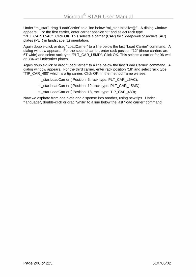
Microlab® STAR User Manual
Page 206 of 225 610766/02
Under “ml_star”, drag “LoadCarrier” to a line below “ml_star.Initialize();”. A dialog windowappears. For the first carrier, enter carrier position “6” and select rack type“PLT_CAR_L5AC”. Click OK. This selects a carrier (CAR) for 5 deep-well or archive (AC)plates (PLT) in landscape (L) orientation.
Again double-click or drag “LoadCarrier” to a line below the last “Load Carrier” command. Adialog window appears. For the second carrier, enter rack position “12” (these carriers are6T wide) and select rack type “PLT_CAR_L5MD”. Click OK. This selects a carrier for 96-wellor 384-well microtiter plates.
Again double-click or drag “LoadCarrier” to a line below the last “Load Carrier” command. Adialog window appears. For the third carrier, enter rack position “18” and select rack type“TIP_CAR_480” which is a tip carrier. Click OK. In the method frame we see:
ml_star.LoadCarrier ( Position: 6, rack type: PLT_CAR_L5AC);
ml_star.LoadCarrier ( Position: 12, rack type: PLT_CAR_L5MD);
ml_star.LoadCarrier ( Position: 18, rack type: TIP_CAR_480);
Now we aspirate from one plate and dispense into another, using new tips. Under"language", double-click or drag “while” to a line below the last “load carrier” command.

Microlab® STAR User Manual
610766/02 Page 207 of 225
In the method frame appears
while()
{
}
Position the cursor between the parentheses () and double-click “sequence” under “variable”in the command frame. In the dialog box select “ ml_star.Source” on the left and“GetCurrentPosition()” on the right and click OK. This results in:
while (ml_star.Source.GetCurrentPosition ( ) )
Now add by hand the condition “> 0”
while (ml_star.Source.GetCurrentPosition ( ) > 0 )
This means “as long as the position of the source well is greater than zero (or the operationis not finished), do the following”. When the position reads zero, the sequence has beenworked through completely.
Now we enter the pipetting commands between the curly brackets.
Under the submenu “ml_star”, double-click or drag the single steps. Now double-click or dragtip pick up. The same dialog box as in the graphical method editor appears.
���
���� �������������������/�)��������������� � � ����������������
Choose the same settings as in the example with the graphical method editor. The same istrue for the following aspiration, dispense, and tip eject steps.
We should now see the following lines in the programming window:
ml_star.TipPickUp (Channel (1..8): oooooooo , Sequence: ml_star.Tip , Tip type: StandardVolumeTip);
This command picks up standard tips without filter on all used channels from the sequence ofthe tip rack, i.e. from the tip rack.
ml_star.Aspirate (Channel (1..8): oooooooo , Sequence: ml_star.Source,
Liquid name: StandardVolume_Water_DispenseJet, Volume: 50 µl,
LLD settings: Capacitive: on - Pressure: off, Liquid following: on );
This command aspirates liquid on all used channels from the sequence of the source plate,i.e. from the source plate. The liquid name specified enables the software to use theappropriate parameters. Volume and the settings for liquid level detection are furtherparameters. Here we aspirate following at liquid level.
ml_star.Dispense (Channel (1..8): oooooooo , Sequence: ml_star.Target,
Liquid name: StandardVolume_Water_DispenseJet, Volume: 50 µl,
LLD settings: off, Liquid following: on);
This command dispenses the given volume into the sequence “ml_star.Target”, i.e. into thetarget plate. The liquid name has to be the same as for the aspiration. Here, we dispenseinto an empty plate, therefore LLD is switched off and we dispense in a jet, following from 2mm above the plate bottom.

Microlab® STAR User Manual
Page 208 of 225 610766/02
ml_star.TipEject (Channel (1..8): oooooooo , Waste destination: ml_star.Waste);
This command ejects the tips to the sequence of the waste container “ml_star.Waste”, i.e.into the waste container.
We now need to get the program to keep count of the wells in the sequences, adding one tothe total so far each time a well is copied. Create the following lines below the“ml_star.TipEject” command but above the closing bracket “}”. Under "variables" double-click"sequence" and select “ml_star.Source” and "Operator++" in the right frame. Click OK.Repeat this for the other sequences until you have written
ml_star.Source++;
ml_star.Target++;
ml_star.Tip++;
This tells the system to keep adding to the count of source plate wells, to the count of targetplate wells, and to the count of tips. When 96 wells and tips have been counted, the counterwill go back to zero, thus ending the program in accordance with the “while” statement weinvoked at the beginning. The “++” command automatically adds to the sequence countersthe number of pipettings done so far.
The last lines in the method frame you should see are
}
return;
}
The first bracket “}” finishes the loop of the “while” statement, “return;”, and the last bracket“}” ends the method “TransferPlate”.

Microlab® STAR User Manual
610766/02 Page 209 of 225
Finally, your method should look like this:
Now save your work by selecting Save from the File menu. The Software prompts you toperform a syntax check. Click YES. The result of the syntax check is displayed in the bottomframe of the method editor. If you have typed in the commands correctly, the result should be“0 error(s)”.
Another example is available within your demo methods directory: “copy from tubes toplates”.

Microlab® STAR User Manual
Page 210 of 225 610766/02
�&&�� �!��
�� ������(
��H����
Detailed positional setting for the hardware
�������� �������
Commercial pipetting tip
� �%��
Aliquots are identical small volumes of liquid.
������
To draw up liquid into a pipetting device.
��� ���
Option and hardware assembly that enables automatic loading of the Microlab STAR. Itconsists of a loading head movable in Y direction, which draws the carriers into the MicrolabSTAR and can read the barcodes on them.
���)������$
Hardware unit. On it the carriers can be placed and held outside the Microlab STAR. Theloading tray is attached to the Microlab STAR, to support the automatic loading andunloading process.
=����������
The barcode mask defines the basic structure of a barcode. It is a pattern to which a barcodemust conform. The assignment of a specific labware item can be done this way. Thebarcode mask can require a barcode to contain specific strings at fixed positions. It cancontain wildcards, too.
=����������
Part of the Autoload Option.
=���������� �������
Basic parts of the Microlab STAR with pipetting arm and deck, to which the loading unit andthe options can be added on.

Microlab® STAR User Manual
610766/02 Page 211 of 225
:�����
Manipulable unit for loading on the Microlab STAR. Hardware unit, in or on which elementsstand, and which is transported when the Microlab STAR is loaded (cf. ��� ���).
:������
Includes test tubes, reagent containers, and wells.
:������������������
Barcode for identification of containers. Serves for unambiguous identification of the vessel,e.g. a sample test tube.
:��������� ������
Refers to the loading of manipulable elements onto the Microlab STAR after processing hasbeen started.
-�������������������:���
Covering for the Microlab STAR. Option and assembly with which the work surface of theMicrolab STAR is covered in such a way that it is shielded from user intervention and otheroutside influences (such as dust). At the same time, it protects the user from the movementsof the Microlab STAR. It is transparent.
���
The work surface of the Microlab STAR. It presents at the same time the greatest possiblearea, cf. ��������. The placing of the carriers on it is defined by the 55 tracks, as long asthey are in the operating range of the pipetting area.
������
To distribute quantities of liquid from a pipetting device.
-������
Programs (sequences of commands) which are carried out on the processors of the MicrolabSTAR.
/�����������
Type of error which depends exclusively on faulty functioning of the hardware.
(������
Hardware of the Microlab STAR (mechanics, electronics, and firmware)

Microlab® STAR User Manual
Page 212 of 225 610766/02
(���������������
The commands made available by the firmware for controlling the Microlab STAR.
)�����
Refers to movable items to be placed on the Microlab STAR deck, such as carriers,containers, or racks.
)(��
Higher-level data processing system, generally known as Laboratory InformationManagement System, also LMS.
)�%���
Includes all kinds of liquids, among which are included reagents, controls, standards, washfluids.
))��!)�%����)� ������"
Positive pipetting of liquid which may be achieved either by pressure, or capacitive signaldetection and transfer.
)������&��� ������
The process by which carriers are brought on to the work surface of the Microlab STAR andtaken off again. This can happen automatically by means of the Autoload Option, ormanually.
����
The method contains all instructions as to how the content of the source vessels is to beprocessed. The assignment of the vessels happens "virtually", however; they are positionedin the deck layout definition.
�)����������������
Software running Microlab STAR.
��.�!��������� �"
In general we assume a plate with 96 Wells (8 x 12) 9 mm wide.
There are also plates with 384 Wells (16 x 24 / 4.5 mm), or others with a different size.
.���
Interruption of processing. The current processing steps are ended.

Microlab® STAR User Manual
610766/02 Page 213 of 225
.�����
Transfer of liquids, usually a defined number of aliquots, from one container to another.
.���������
Assembly consisting of at least 8 Pipetting channels, as well as the common X-driving andarm casing.
.�����������
Hardware part of the Pipetting arm, which can be moved horizontally in the Y direction.
.����������
Firmware (-processor-program) which controls a pipetting channel, in which category areincluded the Y and Z pipetting movement, and the LLD.
.�� ���
Pipetting of different liquids in one well:
1,2,3 .... to n, and n to 1,2,3,....
.�����������
Defines what, where, and with what has to happen on the Microlab STAR. It is defined inaccordance with the methods, the loading, and the tasks. These are the foundation stonesof Microlab STAR methods.
����
Grouping of containers in a mechanical, manipulable unit.
����������������
Barcode for Rack identification.
������������
Means that every channel can access everywhere on the work area.
���
Execution of the processing steps defined in the relevant method with the aim of processingone or more liquids and containers (e.g. MTP). The run is a series of timed commands, inorder to carry out processing on the Microlab STAR according to the processing plan. Therun can be interrupted to load more elements. Then processing goes on according to anewly calculated processing plan, with the run being started again. Loading is not a part ofthe run.

Microlab® STAR User Manual
Page 214 of 225 610766/02
��������
Cancellation of a run by the user or by the Microlab STAR.
����1���� ������
Visualization of the present work status of the Microlab STAR.
����
Refers to a liquid in an unambiguously identified container which is to be processed.
�����
Storage unit for racks
���
Disposable tip for dispensing
��������
Frame that holds the tips together.
�������
Container into which the tips are dropped.
����� ���
Type of dispensing whereby the tip or needle approaches the bottom of the empty containerso close as to allow the dispensed droplet to have simultaneous contact with the tip orneedle and the container bottom.
����
Note of a status during a processing
���
A narrow container for liquid, usually having a circular cross-section, and a cylindrical length-section.
���
User of the product. Levels of user proficiency are not distinguished by the system.
1����������M�
Option. Aid to check the functions of the Microlab STAR, including adjustment.

Microlab® STAR User Manual
610766/02 Page 215 of 225
����:������
A device on the Microlab STAR deck to collect used disposable tips.
�
The individual hollow in the MTP.
� �$�
Geometrical shape of the well, such as U, V, or flat.
�������������������
Type of dispensing whereby tip or needle touches side of container and thus releases thedroplet. Not possible with Microlab STAR.
��������
The area on the Microlab STAR, to which access is provided during processing. Elements tobe pipetted can be placed in this area.
���� ��
Information sent from outside the system, as to what method(s) is (are) to be executed onthe Microlab STAR, and with what liquid.

Microlab® STAR User Manual
Page 216 of 225 610766/02
�� �� �3
Access rights 4, 52
Accessories 1, 3, 29, 32
Adding labware 4, 59, 60, 61, 62, 120,184, 206, 216
Air displacement 3, 14, 25
Aliquot 6, 23, 25, 28, 80, 82, 83, 84, 87,155, 157, 158, 185, 233
Aspiration 3, 8, 14, 15, 16, 17, 18, 19, 20,21, 22, 23, 25, 26, 27, 42, 49, 52, 59,76, 77, 79, 80, 82, 83, 84, 85, 87, 88,89, 90, 97, 98, 106, 112, 114, 115, 116,135, 136, 141, 144, 145, 146, 153, 154,157, 158, 168, 172, 173, 181, 194, 199,200
Autoload 3, 6, 31, 36, 37, 46, 91, 110,133, 134, 141, 158, 190, 192, 193, 196,228, 233, 235
Automated Vacuum System (AVS) 4, 5,32, 38, 39, 40, 41, 119, 120, 121, 122,124, 125, 126, 127, 128, 129, 130
Barcodes 6, 9, 31, 32, 36, 53, 55, 103,141, 184, 187, 190, 197, 198, 203, 204
Batch methods 5, 106
Binding step return values 5, 104
Biohazardous material 11
Carriers 6, 15, 16, 18, 29, 31, 32, 33, 34,36, 59, 60, 61, 62, 81, 85, 92, 97, 98,99, 132, 133, 141, 147, 148, 149, 154,155, 158, 169, 174, 183, 184, 185, 186,187, 189, 190, 192, 196, 198, 216, 217,218
Carriers, temperature-controlled 4, 6, 32,36, 37, 38, 60, 99, 104, 174, 178, 179
Channels (pipetting) 10, 15, 16, 19, 20,25, 29, 33, 47, 48, 55, 59, 64, 67, 89,92, 93, 94, 95, 97, 98, 106, 140, 144,197, 198, 199, 200
Cherry picking 6, 158
Clot detection 3, 27
Collision 59
Configuration (instrument) 4, 29, 31, 52,53, 54, 55, 56, 71, 110, 117, 118, 121,141, 175, 195, 196, 200, 203
Configuration Editor 29, 52, 54, 56, 110,141, 175, 195, 203
Container 6, 10, 11, 14, 15, 16, 19, 20,21, 23, 29, 34, 36, 40, 55, 59, 64, 67,83, 84, 88, 97, 98, 145, 147, 199, 207,209, 211, 212, 215, 234, 237, 238
Contamination and decontamination 3,11, 15, 20
Control PC 42
Deck 4, 9, 15, 28, 29, 30, 33, 34, 36, 37,38, 41, 42, 46, 49, 50, 51, 53, 54, 55,57, 58, 59, 60, 62, 63, 64, 65, 66, 67,68, 76, 79, 80, 81, 91, 92, 95, 97, 107,109, 110, 111, 112, 119, 120, 121, 122,131, 132, 133, 134, 138, 141, 148, 149,151, 152, 154, 155, 158, 159, 160, 167,169, 174, 184, 189, 190, 191, 192, 193,195, 197, 206, 216, 227, 234
Deck layout 30, 33, 42, 49, 50, 51, 54, 57,58, 59, 60, 64, 67, 68, 76, 79, 80, 91,95, 107, 109, 110, 111, 119, 120, 121,122, 131, 132, 133, 138, 141, 148, 149,151, 152, 155, 159, 160, 169, 174, 184,189, 190, 191, 195
Dispensing 3, 8, 14, 15, 18, 19, 20, 21,22, 23, 25, 42, 48, 49, 52, 76, 79, 80,82, 83, 84, 85, 87, 88, 89, 90, 98, 106,112, 114, 115, 116, 135, 136, 141, 144,145, 146, 153, 154, 157, 158, 173, 181,194, 197, 199, 209
Disposables 3, 33
Disposal (of instrument) 4, 46
Errors 6, 22, 27, 55, 79, 80, 85, 89, 90,92, 94, 95, 103, 106, 108, 115, 124,126, 136, 147, 197, 198, 199, 200, 201,202
File structure 4, 53
Firmware 4, 11, 42, 98
Fuses 43, 45

Microlab® STAR User Manual
610766/02 Page 217 of 225
Graphical Method Editor 5, 52, 76, 101,107, 108, 131, 133
Gripper (robotic hand) 99
HSL Method Editor 5, 7, 51, 52, 53, 76,96, 102, 107, 108, 111, 131, 197
Initialization 82, 97, 99, 125, 127, 140,158, 175, 177
Installation 4, 42
iSWAP (internal Swivel-Arm Platehandler)4, 6, 38, 41, 99, 184, 187
Labware 4, 6, 16, 18, 28, 33, 50, 51, 53,57, 59, 60, 61, 62, 63, 64, 65, 66, 67,68, 69, 70, 71, 91, 120, 121, 149, 155,184, 189, 190, 192, 204, 206, 207, 208,216, 217, 235
Labware Editor 6, 206, 216
Libraries 5, 53, 62, 101, 102, 103, 108,161, 164, 166, 167, 174, 179, 184, 206
Life cycle (of instrument) 46
Liquid Classes 3, 5, 9, 20, 21, 22, 23, 25,27, 52, 81, 112, 114, 116, 117, 118,135, 144, 146
Liquid Editor 5, 21, 52, 112, 113, 116, 117
Liquid level detection (LLD) 9, 10, 15, 16,17, 18, 22, 23, 27, 88, 97, 98, 136, 144,145, 154, 158, 199, 209, 218
Liquids 3, 5, 8, 9, 10, 11, 12, 14, 15, 16,17, 18, 19, 20, 21, 22, 23, 25, 27, 35,36, 37, 40, 47, 48, 52, 55, 67, 81, 83,88, 89, 97, 98, 110, 112, 113, 114, 115,116, 117, 118, 135, 144, 145, 146, 148,153, 158, 169, 197, 199, 201, 203, 209
Loading and unloading 6, 28, 31, 37, 38,59, 80, 91, 92, 110, 133, 135, 147, 154,157, 158, 167, 168, 183, 189, 190, 192,193, 196, 197
Maintenance 4, 10, 11, 46
Method linking 5, 111
Methods 5, 6, 7, 9, 26, 38, 41, 42, 48, 49,50, 51, 52, 53, 54, 56, 57, 59, 66, 67,76, 77, 78, 79, 80, 81, 82, 89, 91, 93,96, 99, 100, 101, 102, 103, 104, 106,107, 108, 109, 110, 111, 112, 119, 121,122, 123, 126, 128, 130, 131, 132, 133,134, 137, 138, 139, 140, 141, 147, 148,152, 154, 155, 157, 158, 159, 160, 161,
162, 163, 165, 169, 170, 174, 175, 177,178, 180, 183, 185, 186, 189, 190, 191,192, 193, 194, 195, 197, 200, 201, 203,205
Microtiter plates (MTP) 10, 12, 18, 28, 29,31, 33, 34, 59, 67, 80, 98, 148, 155,158, 160, 168, 197, 206, 207, 212, 214,218
Options 1, 3, 29
Pause 29, 110, 194, 195
Pipetting 3, 6, 14, 20, 21, 29, 30, 47, 67,81, 82, 84, 85, 87, 92, 94, 106, 112,116, 135, 137, 141, 142, 144, 152, 153,155, 157, 158, 168, 185, 236
Plate handling 6, 184
Position 19, 36, 37, 41, 51, 55, 60, 61, 63,64, 65, 67, 68, 69, 70, 71, 78, 83, 84,90, 91, 97, 98, 99, 120, 125, 142, 143,144, 145, 147, 154, 158, 166, 167, 169,172, 179, 180, 181, 184, 186, 187, 192,198, 209
Power (electrical) 4, 42, 43, 45
Probe 5, 51, 64, 65, 67, 71
Rack 6, 15, 55, 63, 65, 67, 72, 93, 94, 97,143, 149, 155, 206, 207, 208, 209, 211,212, 214, 215, 216, 236, 237
Run 5, 6, 10, 15, 29, 42, 49, 50, 51, 52,54, 57, 67, 76, 84, 85, 91, 109, 110,111, 126, 137, 140, 148, 154, 158, 189,190, 191, 192, 194, 195, 196, 203, 204
Run abort 10, 56, 79, 89, 90, 110, 126,195, 201
Safety 3, 9, 11
Sequence Editor 4, 67, 149, 150, 160
Sequences 4, 6, 50, 51, 55, 57, 67, 68,69, 70, 71, 72, 73, 74, 78, 81, 82, 83,84, 85, 86, 87, 89, 90, 91, 93, 95, 97,98, 99, 106, 131, 134, 135, 140, 141,142, 143, 144, 145, 147, 149, 150, 151,153, 154, 155, 157, 158, 160, 164, 166,167, 168, 169, 170, 171, 172, 173, 174,179, 180, 181, 184, 185, 186, 187, 192
Single steps 5, 6, 80, 81, 82, 84, 90, 95,106, 110, 138, 139, 140, 155, 169, 172,177, 194, 200

Microlab® STAR User Manual
Page 218 of 225 610766/02
SMART steps 5, 6, 37, 79, 80, 81, 82, 93,94, 95, 106, 123, 131, 133, 148, 155,158, 169, 173, 200
Software 1, 4, 8, 11, 13, 21, 29, 30, 36,38, 41, 42, 46, 49, 50, 51, 52, 54, 59,64, 77, 82, 107, 111, 112, 119, 127,131, 155, 174, 184, 203
Sorting 5, 68, 69, 70, 71, 72, 74
Specifications (technical) 4, 47
Teaching box 55
Teaching mode 4, 55, 64, 65
Tip counter 6, 53, 174
Tip eject 3, 20, 95, 106, 141, 197
Tip pick-up 81, 84, 94, 106, 141, 143, 144
Tip rack 15, 29, 59, 60, 61, 81, 93, 132,143, 149, 151, 155, 159, 160, 174, 207,218
Tips, disposable 3, 6, 9, 10, 11, 14, 15,16, 17, 18, 19, 20, 21, 22, 23, 25, 26,27, 29, 30, 33, 35, 47, 48, 53, 55, 59,60, 61, 62, 65, 80, 81, 82, 83, 84, 88,91, 93, 94, 95, 97, 106, 114, 115, 116,131, 132, 135, 140, 141, 143, 144, 145,147, 149, 151, 153, 155, 157, 159, 160,
172, 174, 178, 179, 180, 181, 183, 192,197, 206, 207, 209, 218
Tolerance 187
Track 4, 55, 59, 60, 62, 64, 120, 149, 216,217
Training 4, 46
Tubes 6, 9, 10, 12, 15, 16, 18, 28, 29, 30,31, 32, 33, 55, 59, 60, 62, 80, 82, 83,85, 86, 87, 91, 148, 149, 151, 154, 155,169, 174, 197, 198, 207, 209, 216
Variables 5, 15, 18, 76, 78, 82, 100, 101,103, 104, 107, 108, 124, 126, 140, 163,165, 166, 167, 178, 179, 180, 183
Verification 4, 46, 47
Walk-away 90, 200, 202
Wash station 15, 20, 32, 34, 35, 36, 42,45, 81, 93, 94, 97, 98, 169
Waste station 10, 11, 20, 29, 34, 36, 38,40, 55, 59, 64, 81, 84, 94, 97, 124, 130,140, 147
Well 8, 18, 47, 55, 59, 61, 65, 67, 89, 90,109, 131, 142, 155, 157, 159, 169, 178,187, 192, 197, 216, 218
Worklist 5, 103, 104
Microlab® STAR User Manual
610766/02 Page 219 of 225
� "�/������(��������
CE, CSA and UL conformity are maintained for Microlab STAR. See the Declaration ofConformity for the instrument reproduced on the next page.
"� �������������!��I$����� ���� �J
This equipment has been tested and found to comply with the limits for a Class A digitaldevice, pursuant to both Part 15 of the FCC Rules and the radio interference regulations ofthe Canadian Department of Communications. These limits are designed to providereasonable protection against harmful interference when the equipment is operated in acommercial environment. This equipment generates, uses and can radiate radio frequencyenergy and, if not installed and used in accordance with the present user manual, may causeharmful interference to radio communications. Operation of this equipment in a residentialarea is likely to cause harmful interference, in which case the user will be required to correctthe interference at his own expense.
Pursuant to the Canadian Radio Interference Regulations, ICES-001 Notice for Industrial,Scientific and Medical Radio Frequency Generators, this ISM apparatus meets allrequirements of the Canadian Interference-Causing Equipment Regulations. Please notethat this requirement is only for generators which operate at over 10,000 Hz.
���5�����0��/�����!�
The Microlab STAR is ��� intended specifically to be used as an “In Vitro Diagnostic Device”.The following text defines an “In Vitro Diagnostic Device” [from: Directive 98/79/EC of theEuropean Parliament and of the Council of 1998-10-27 on in vitro diagnostic medicaldevices]:
'[...] ������� diagnostic medical device' means any medical device which is a reagent,product, calibrator, control material, kit, instrument, apparatus, equipment, or system,whether used alone or in combination, intended by the manufacturer to be used ������� forthe examination of specimens, including blood and tissue donations, derived from the humanbody, solely or principally for the purpose of providing information:
- concerning a physiological or pathological state, or
- concerning a congenital abnormality, or
- to determine the safety and compatibility with potential recipients, or
- to monitor therapeutic measures.
Specimen receptacles are considered to be ������� diagnostic medical devices. 'Specimenreceptacles' are those devices, whether vacuum-type or not, specifically intended by theirmanufacturers for the primary containment and preservation of specimens derived from thehuman body for the purpose of ������� diagnostic examination.
Products for general laboratory use are not ��������diagnostic medical devices unless suchproducts, in view of their characteristics, are specifically intended by their manufacturer to beused for in vitro diagnostic examinations; [...]'

Microlab® STAR User Manual
Page 220 of 225 610766/02
0�!��������������������(
��/��� ���=�����?��I&:/ JC3@=�����?L���?� ������������������ ������������
Wir, Hamilton Bonaduz AG,CH-7402 Bonaduz/Schweizbestätigen, dass dasfolgende Produkt
La société Hamilton BonaduzAG, CH-7402Bonaduz/Suisse confirmeque l’instrument ci-dessous
Product name
S/N
��!���������"
....
meets the following ECdirectives (including allapplicable amendments):
mit den folgenden EG-Richtlinien (einschliesslichaller zutreffendenAenderungen)übereinstimmt:
est en conformité avec lesdirectives CE suivantes (ycompris leursamendements, le caséchéant):
EMC Directive89/336/EEC
Low Voltage Directive 73/23/EEC
Applied harmonised standards:
Safety EN 61010-1 (1993) + A2 (1995)
EN 60825-1 (1994) + A11 (1996)
Emission
Immunity
EN 61326 (1997) + A1 (1998) class B
EN 61326 (1997) + A1 (1998)
(laboratory equipment)
Additional Information:
C US
Canada, USACAN/CSA-C22.2 No. 1010.1-92
UL Std. No. 3101-1
FCC, Part 15, class A
Microlab® STAR User Manual
610766/02 Page 221 of 225
0� �� ����/������������
A current checklist is available from HAMILTON.

Microlab® STAR User Manual
Page 222 of 225 610766/02

Microlab® STAR User Manual
610766/02 Page 223 of 225
����� ���,�����������=�����!�����&��������(
��� ����!���!��&��������(�������� �� �:�����������
Chemical 1.4310 EPDM FPM PE NBR PEEK POM PP PTFE PVC PVDF SI
Acetic acid, 20% 1 2 3 1 3 1 1 1 1 1 1 2
Acetic acid, glacial 1 4 4 1 4 1 4 1 1 4 1 2
Acetone 1 1 4 2 4 1 1 1 1 0 3 3
Acetonitrile 1 3 3 1 4 0 3 3 1 0 1 0
Ammonium hydroxide,5% 1 1 2 1 2 1 1 1 1 0 2 1
Chloroform 1 4 3 3 4 1 4 3 1 4 1 4
Deionized water 1 1 1 1 1 1 1 1 1 1 1 1
Dimethyl formamide 1 2 4 1 4 1 1 1 1 4 4 2
Dimethyl sulfoxide 1 3 3 1 4 0 1 1 1 4 3 0
Ethyl acetate 1 3 4 2 4 1 1 1 1 4 3 2
Hexane 1 4 1 3 1 1 1 2 1 4 1 4
Hydrochloric acid, 20% 4 1 1 1 4 1 4 1 1 1 1 3
Isopropyl alcohol 1 1 1 1 3 1 1 1 1 4 1 1
Methanol 1 1 3 1 3 1 1 1 1 3 1 1
Methylene chloride 1 4 3 4 4 2 3 3 1 4 1 4
Nitric acid, 5-10% 1 2 1 1 4 1 4 1 1 1 1 2
Nitric acid, 70% 1 4 2 3 4 1 4 4 1 4 1 4
Phosphate buffer 1 1 1 1 1 0 1 1 1 0 1 4
Phosphoric acid, 85% 2 3 1 1 4 0 4 1 1 1 1 3
Potassium hydroxideconc. 1 1 4 1 3 1 3 1 1 0 2 3
Sodium acetate 1 1 3 1 3 0 1 1 1 3 1 4
Sodium borate 1 1 1 1 3 0 1 1 1 1 1 1
Sulfuric acid, 1-75% 2 4 1 1 4 2 4 1 1 1 1 3
Urine 1 1 1 1 1 1 1 1 1 1 1 1
Triethylamine 1 4 3 0 3 0 1 4 1 0 3 4
Toluene 1 4 1 3 4 1 1 3 1 4 1 4
����!���IS�(����!� ���������.�������J=
1 = no effect, little or no noticeable change
2 = slight corrosion or discoloration
3 = Moderate corrosion or other change in physikal properties or dimensions; not recommended forcontinuous contact
4 = severe corrosion or physical change;prolonged contact not recommended
0 = No data

Microlab® STAR User Manual
Page 224 of 225 610766/02
���������
1.4310 Steel
EPDM Ethylene-propylene-elastomer
FPM Fluoroelastomer
NBR Acrylnitril-butadiene-rubber
PE Polyethylene
� ��������� ��������������%����
PEEK Polyetheretherketone
POM Polyoxymethylene
PP Polypropylene
PTFE Polytetrafluorethylene
PVC Polyvinylchloride
PVDF Polyvinylidenefluoride
SI Silikon
��� ����!���!��&��������(������/������������!��:�����������
Chemical 1.4310 EPDM FPM PE PEEK PP PTFE PVDF SI
Acetic acid, 20% 1 2 3 1 1 1 1 1 2
Acetic acid, glacial 1 4 4 1 1 1 1 1 2
Acetone 1 1 4 2 1 1 1 3 3
Acetonitrile 1 3 3 1 0 3 1 1 0
Ammonium hydroxide, 5% 1 1 2 1 1 1 1 2 1
Chloroform 1 4 3 3 1 3 1 1 4
Deionized water 1 1 1 1 1 1 1 1 1
Dimethyl formamide 1 2 4 1 1 1 1 4 2
Dimethyl sulfoxide 1 3 3 1 0 1 1 3 0
Ethyl acetate 1 3 4 2 1 1 1 3 2
Hexane 1 4 1 3 1 2 1 1 4
Hydrochloric acid, 20% 4 1 1 1 1 1 1 1 3
Isopropyl alcohol 1 1 1 1 1 1 1 1 1
Methanol 1 1 3 1 1 1 1 1 1
Methylene chloride 1 4 3 4 2 3 1 1 4
Nitric acid, 5-10% 1 2 1 1 1 1 1 1 2
Nitric acid, 70% 1 4 2 3 1 4 1 1 4
Phosphate buffer 1 1 1 1 0 1 1 1 4
Phosphoric acid, 85% 2 3 1 1 0 1 1 1 3
Potassium hydroxide conc. 1 1 4 1 1 1 1 2 3
Sodium acetate 1 1 3 1 0 1 1 1 4
Sodium borate 1 1 1 1 0 1 1 1 1
Sulfuric acid, 1-75% 2 4 1 1 2 1 1 1 3
Urine 1 1 1 1 1 1 1 1 1
Triethylamine 1 4 3 0 0 4 1 3 4
Toluene 1 4 1 3 1 3 1 1 4

Microlab® STAR User Manual
610766/02 Page 225 of 225
����!���IS�(����!� ���������.�������J=
1 = no effect, little or no noticeable change
2 = slight corrosion or discoloration
3 = moderate corrosion or other change in physical properties or dimensions; not recommended for continuous contact
4 = severe corrosion or physical change; prolonged contact not recommended
0 = No data
���������
1.4310 Steel
EPDM Ethylene-propylene-elastomer
FPM Fluoroelastomer
PE Polyethylene
� ��������� ��������������%����
PEEK Polyetheretherketone
PP Polypropylene
PTFE Polytetrafluorethylene
PVDF Polyvinylidenefluoride
SI Silicon