Embed Size (px)
Citation preview
ii
Force Characterization of an Electromagnetic Linear Actuator
TAWFIK AHMED YAHYA
A report submitted in partial fulfillment of the requirements for the degree of
Mechatronic engineering
Faculty of Electrical Engineering
UNIVERSITI TEKNIKAL MALAYSIA MELAKA
MAY 2015
iii
I hereby declare that I have read through this report entitled “Force Characterization of an
Electromagnetic Linear Actuator” and found that it has comply the partial fulfillment for
awarding the degree of Bachelor of Mechatronic engineering.
Signature: .......................................................
Supervisor: DR. MARIAM BINTI MD GHAZALY
Date: 1/5/2015
iv
I declare that this report entitle “Force Characterization of an Electromagnetic Linear
Actuator” is the result of my own research except as cited in the references. The report has
not been accepted for any degree and is not concurrently submitted in candidature of any
other degree.
Signature: ……………………………………
Name: TAWFIK AHMED YAHYA
Date: 1/5/2015

v
ACKNOWLEDGMENT
Special to my beloved mother and father who always standby my side in giving
supports morally and financially. Special thanks also to my special supervisor Dr.
Mariam for her great efforts helping me toward success of this project.
vi
ABSTRACT
Electromagnetic actuators are nowadays used in a vast variety of applications that
require high thrust, high accuracy and different working ranges. The increasing
advancements in the usage of electromagnetic actuators rises the need for more and more
improvements in electromagnetic actuators especially in term of output force and working
range. The thesis present an extensive characterizing study of two novel electromagnetic
actuators each with different construction and characteristics aiming to analyze the behavior
and output characteristics of the two designs and how these characteristics are effected by
parameters and size variations. The two actuators are Tubular Linear Reluctance Actuator
and Tubular Linear Permanent magnet with Halbach array Actuator. Each one of the designs
has its own working principle, the Tubular Linear Reluctance Actuator employs induction
motor principle where no permanent magnet is used and the other employs the synchronous
motor principle where the mover is built of permanent magnets with one of the latest
successful improvement of electromagnetic actuators. The study covers the variation of three
parameter for each actuator air gap, number of turns and size. A comparative section is also
presented for the purpose of comparison. The study concentrated extensively on the two
characteristics of both actuators which are output thrust force and working range as they are
considered two main concerns of any actuator design. The simulation is used to show the
differences between the two design in many design aspects such as force, displacement and
effects of parameters variations .The applied simulation is performed using 3D finite-
element Ansoft software which is cabable of showing the magnetic field distribution in the
whole actuator and predicting the strength and length of the output stroke.
vii
ABSTRAK
Penggerak elektromagnet yang kini digunakan dalam pelbagai besar aplikasi yang
memerlukan teras yang tinggi, ketepatan yang tinggi dan julat kerja yang berbeza. Kemajuan
peningkatan dalam penggunaan penggerak elektromagnet meningkat keperluan untuk lebih
banyak penambahbaikan dalam penggerak elektromagnet terutama dari segi daya
pengeluaran dan pelbagai kerja. Tesis membentangkan kajian mencirikan banyak dua
penggerak elektromagnet novel masing-masing dengan pembinaan dan ciri-ciri yang
bertujuan untuk menganalisis tingkah laku dan output ciri-ciri kedua-dua reka bentuk dan
bagaimana ciri-ciri ini dilaksanakan dengan parameter dan variasi saiz yang berbeza. Kedua-
dua penggerak adalah tiub Linear Keengganan aktuator dan tiub Linear magnet Kekal
Halbach pelbagai aktuator. Setiap satu daripada reka bentuk yang mempunyai prinsip sendiri
kerja, yang tiub Linear Keengganan aktuator menggunakan prinsip motor induksi di mana
tidak ada magnet kekal digunakan dan satu lagi menggunakan prinsip motor segerak mana
penggerak itu dibina daripada magnet kekal dengan satu peningkatan berjaya terkini
penggerak elektromagnet. Kajian ini meliputi perubahan tiga parameter bagi setiap ruang
udara penggerak, bilangan lilitan dan saiz. Sebahagian perbandingan juga dikemukakan
untuk tujuan perbandingan. Kajian tertumpu meluas di kedua-dua ciri-ciri kedua-dua
penggerak yang output daya tujah dan pelbagai kerja kerana mereka dianggap dua
kebimbangan utama mana-mana reka bentuk penggerak. Simulasi ini digunakan untuk
menunjukkan perbezaan di antara kedua-dua reka bentuk dalam aspek reka bentuk banyak
seperti kekerasan, anjakan dan kesan parameter variasi .The digunakan simulasi dilakukan
menggunakan unsur terhingga perisian Ansoft 3D yang cabable menunjukkan taburan
medan magnet dalam seluruh penggerak dan meramalkan kekuatan dan panjang output
stroke.The FEM hasil analisis dan keputusan output strok dibentangkan.
viii
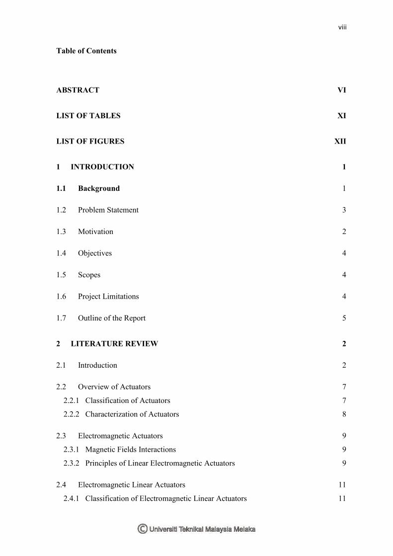
Table of Contents
ABSTRACT VI
LIST OF TABLES XI
LIST OF FIGURES XII
1 INTRODUCTION 1
1.1 Background 1
1.2 Problem Statement 3
1.3 Motivation 2
1.4 Objectives 4
1.5 Scopes 4
1.6 Project Limitations 4
1.7 Outline of the Report 5
2 LITERATURE REVIEW 2
2.1 Introduction 2
2.2 Overview of Actuators 7
2.2.1 Classification of Actuators 7
2.2.2 Characterization of Actuators 8
2.3 Electromagnetic Actuators 9
2.3.1 Magnetic Fields Interactions 9
2.3.2 Principles of Linear Electromagnetic Actuators 9
2.4 Electromagnetic Linear Actuators 11
2.4.1 Classification of Electromagnetic Linear Actuators 11
ix
2.4.2 Classification of Tubular Electromagnetic Linear Actuators 12
2.5 Advantages of Electromagnetic Linear Actuators 13
2.6 Improvement of Tubular Electromagnetic Linear Actuators 13
2.7 Thrust Calculation of the Tubular Inductance and PM Actuators 15
2.7.1 Inductance Linear Actuator 15
2.7.2 Tubular Linear Actuator with Halbach Array 17
2.8 Previous Work Done on Tubular Linear Electromagnetic Actuators 19
2.9 Literature review summary 22
3 METHODOLOGY 23
3.1 Design Strategy 23
3.2 Conceptual Design 26
3.2.1 First Design 26
3.2.2 Second Design 27
3.3 Designs structure and initial parameters 28
3.3.1 First Design (Tubular Linear Reluctance Actuator with step windings) 28
3.3.2 Second design (Tubular Linear Permanent Magnet with Halbach Array Actuator)
31
3.4 Working Principle 34
3.4.2 Second design 35
3.5 Simulation Method 37
3.5.1 First Design 39
3.5.2 Second design 41
3.6 Force Characterization Set Up 43
4 RESULTS & DISSCUSTION 45
4.1 Magnetic field distribution 45
x
4.1.1 First Design 45
4.1.2 Second design 47
4.2 Thrust Analysis 49
4.2.1 First Design 49
4.2.2 Second design 52
4.3 Parameters Variations 55
4.3.1 Air Gap Variation 56
4.3.2 First Design 56
4.3.3 Second design 57
4.4 Number of Turn’s Variation 60
4.4.1 First Design 60
4.4.2 Second design 62
4.5 Size Scale Variation 64
4.5.1 First Design 64
4.5.2 Second design 65
4.6 Comparison between the Two Designs 67
4.6.1 Thrust 67
4.6.2 Parameters Variation 67
5 CONCLUSION & RECOMMINDATION FOR FUTURE WORK 70
6 REFERENCES 71
APPENDIX 73
xi
LIST OF TABLES
Table Title Page number
2-1 : Classes of actuators 7
2-2 : Characterization of linear actuators 8
3.1 : Parameters of the Tubular Linear Reluctance Actuator with step windings 28
3-2 : Parameters of the winding’s steps 28
3-3 : Parameters of the Tubular Linear Permanent Magnet with Halbach Array
Actuator 31
4-1 Charactristics comparision between the two designs 67
4-2 Comparison of parameters variations between the two designs 67
xii
LIST OF FIGURES
Figure Title Page Number
3.1 Flow chart of the design process 24
3.2 : Conventional coil arrangement. 26
3.3 : Proposed coil arrangement. 26
3.4 : Halbach array field distribution. 27
3.5 : Cylindrical Halbach array [22] 27
3.6 : Top view of the reluctance actuator 29
3.7 : Dimensions of step windings of the reluctance actuator represented in side view
30
3.8 : 3D view of the Tubular Linear Reluctance Actuator with step windings 30
3.9 : Top view of the permanent magnet actuator 32
3.10 : Side view of the permanent magnet actuator 33
3.11 : 3D view Tubular Linear Permanent Magnet with Halbach Array Actuator 33
3.12 Magnetic field in the step winding actuator 35
3.13 : A sample of the distribution of magnetic field in a Halbach array 36
3.14 Magnetic field in the Permanent magnet actuator 36
3.15 Process of simulation in the Maxwell software 38
3.16 Section of reluctance actuator indicating the current direction 39
3.17 Current direction in step windings actuator in the Maxwell software 40
3.18 Section of permanent magnet actuator indicating the current direction 41
3.19 Current directions in permanent magnet actuator in the Maxwell software 42
3.20 Magnetization setting for the Halbach array magnets 42
4.1 Magnetic field distribution in reluctance step windings actuator (side view) 46
4.2 Magnetic field distribution in reluctance step windings actuator (top view) 46
4.3 Magnetic field distribution in the permanent magnet actuator (side view) 47
4.4 Magnetic field distribution in the permanent magnet actuator where the
magnetization direction of the magnet is in the x direction (top view) 48
4.5 Magnetic field distribution in the permanent magnet actuator where the
magnetization direction of the magnet is in the z direction (top view) 48
4.6 0 to 90 mm displacement of step windings actuator 49
4.7 Force vs 0-90 mm displacement of step windings actuator (positive direction) 50
4.8 Displacement of step windings actuator (negative direction) 51
xiii
4.9 Displacement from 0 to 90 mm of permanent magnet actuator (positive direction)
52
4.10 Force vs displacement 0-90 mm for permanent magnet actuator 53
4.11 Displacement from 90 to 0 mm of permanent magnet actuator (negative direction)
54
4.12 Force vs displacement -90-0 mm for permanent magnet actuator 55
4.13 Air gap variation in real design 56
4.14 Force vs input current for six different air gaps 57
4.15 Air gap variation in real design 0.5 to 1.5 mm 58
4.16 Force vs input current for six different air gaps 58
4.17 Air gap variation in real design 0.5, 2 and 1.5 mm 59
4.18 Force vs input current for three different air gaps 59
4.19 Five different sets of turns applied to the design 60
4.20 Force vs input current for five different sets of number of turns 61
4.21 Five different number of turns applied to the design 62
4.22 Force vs input current for five different number of turns 63
4.23 Six different sizes of the design 64
4.24 Force vs displacement for six different sizes of the design 65
4.25 Six different sizes of the design 66
4.26 Force vs displacement for six different sizes of the design 66
CHAPTER 1
1 INTRODUCTION
1.1 Background
Constant technology advancements have made people’s live convenient and
comfortable, the effects of technologies that had arrived from little inventions and led to very
major advances can be clearly noticed, transmission is a significant one of them. The
evolution of transmission technology has a major contribution in current easy and convenient
live .Transmission is seen almost in every sector of today’s technologies ranging from
primary and heavy industrial automation to advance electronics and aerospace actuation.
Electromagnetic actuators are of the most well-known types of linear transmissions
work by converting electric and /or magnetic power to mechanical motion through magnetic
field interactions. Electromagnetic actuators have lately became an area of interest to a huge
number of researchers as they found it compact sector toward efficiency drive improvement
,energy saving and significant alternative for many other types of actuators such as
piezoelectric and rotary to linear actuators. Electromagnetic actuators provide a various
number of advantages over other types of actuators such as higher force, lower needed power
and higher efficiency which are comprehensively detailed in chapter 2. In this thesis two
linear electromagnetic actuators will be designed and characterized for the purpose of
comparison between different novel topologies of designing linear electromagnetic
actuators.
2
1.2 Motivation
The recent advancement of linear actuators and the increasing demand for energy and
environment saving gave rise of intensive use of electromagnetic actuators especially the
types of electromagnetic actuator which consist mostly from permanent magnets.
Electromagnetic actuators are nowadays replacing many types of actuators and conventional
actuation methods and its future potential is day to day increasing.
Linear electromagnetic actuators provide new actuation method used almost in all todays
advanced technologies such as:
Industrial automation.
Automotive and aerospace actuation.
Robots and medical tools.
Transportation.
It’s well known that two of the most critical problems facing the world today are global
warming and high energy consumption. The usage of linear electromagnetic actuators could
effectively contribute in reducing the large amount of emissions caused by transportation by
implementing the new generations of automobile engines as it contributed in significant
energy saving and mechanical wear in many applications. For example Levitated train, the
usage of Levitated train introduced three to five times reduction of energy utilized by
railroads trains and totally reduced the mechanical wear due to the employment of non-
contact new technology.
The extensive use of electromagnetic actuators rises the need for the characteristics’
optimization of the actuators. By optimizing the structure of the electromagnetic actuator,
many characteristics of the electromagnetics actuator will be improved such as thrust force
and working range. This led to a short conclusion that, more work is needed in order to

3
improve the electromagnetic linear actuators. One such a work can contribute in the modern
evolution of transmission technology.
1.3 Problem Statement
Throughout world’s industries, it is been proven that electromagnetic actuator has
overcome many disadvantages in other types of actuators such as weariness in Electro-
mechanical actuators, high required voltage and short travel in Piezoelectric actuators and
leakage, imprecise positioning in Hydraulic and Pneumatic actuators. However ,
electromagnetic actuator still suffer the problem of low to average force production and
designing an actuator with high force, long stroke and more compact geometry is still
challenging work in many applications which rises the need for more and more improvement
efforts especially in term of output force and working range. Hence, a great deal of efforts
in the last decade have been dedicated toward the improvement of this type of actuators. This
thesis focuses on characterizing two Electromagnetic linear actuators each with different
construction and arrangement of coils and magnets. The two designs are considered to
improve the thrust and working range. The two designs are characterized and exclusively
investigated in term of force and working range in which can be considered a contribution
to the extensively increasing advancement of linear electromagnetic actuators.
4
1.4 Objectives
1. To characterize two novel designs of tubular electromagnetic actuator to produce
highest possible thrust force and determine the possible ranges.
2. To analyze the two designs using Finite Element Method (FEM).
3. To compare and evaluate the two designs in term of output forces and working
ranges.
1.5 Scopes
1. Design and characterize two types of tubular linear micro-electromagnetic actuator.
2. Analyze the thrust output force and the working range of the two designs using Finite
Element Method (FEM).
3. Optimize the thrust output force and the working range of the two designs in term of
geometric, size and coil-permanent magnet arrangement.
1.6 Project Limitations
Two design limitations of the project:
1. As the one of the best type of electromagnetic actuator used permanent magnet to
generate its output thrust and with the high price of magnetic materials but the project
is limited to use as less permanent magnet as possible. This limitation caused the
project to choose only one of the actuators with permanent magnet while the other
will use iron.
2. The project is limited to a working range of 100 mm as its maximum.
5
1.7 Outline of the Report
Chapter 1: Introduction-This chapter introduces an overview of the project including
purpose, limitation, and motivation. A general information about the linear actuator and
covered topics of the project are also presented.
Chapter 2: Literature review- This chapter summarize the most relevant concepts and
evolution relating to linear actuators in general and electromagnetic linear actuators in
particular. This includes magnetic interactions, optimization and output force calculations.
Chapter 3: Methodology- This chapter describes the methods and procedures
employed to design the project represented in a flow chart, conceptual design, and structure
of designs. This chapter include also working principles and simulation method of the two
designs of the project. The proposed analysis set up is also presented.
Chapter 4: Results and Discussion - This chapter illustrates the two designs of the
two actuator fully with their complete parameters and discusses obtained results of both
designs. Also a short comparison between designs is presented.
Chapter 5: Conclusion and recommendation- This chapter describes the conclusion
of the project provides some recommendations for future works.
CHAPTER 2
2 LITERATURE REVIEW
2.1 Introduction
Linear motion or what can be called rectilinear motion is a motion which takes place
in a straight line. Linear motion is the basic of all kinds of motions. There are simple and
complex products employing linear motion. These products are used in many kinds of
machinery which are used exclusively to produce other technologies as its considered a main
major part in manufacturing machines such as CNCs.
An actuator is an energy converting device which take one or more power source to
create mechanical work or motion. The motion could be either linear (straight line) or rotary
(rotation about a fixed point) in accordance with the requirements of the needed machine.
The criteria of which an actuator is evaluated are output force, stroke speed and length,
mover mass and power density and so on.
7
2.2 Overview of Actuators
2.2.1 Classification of Actuators
As actuators are energy converting devices, it convert an input from one or more
sources to an output mechanical linear motion in a way which can be controlled using
different methods. This energy conversion can be accomplished through different method
depending on different operation principles and applications. According to different
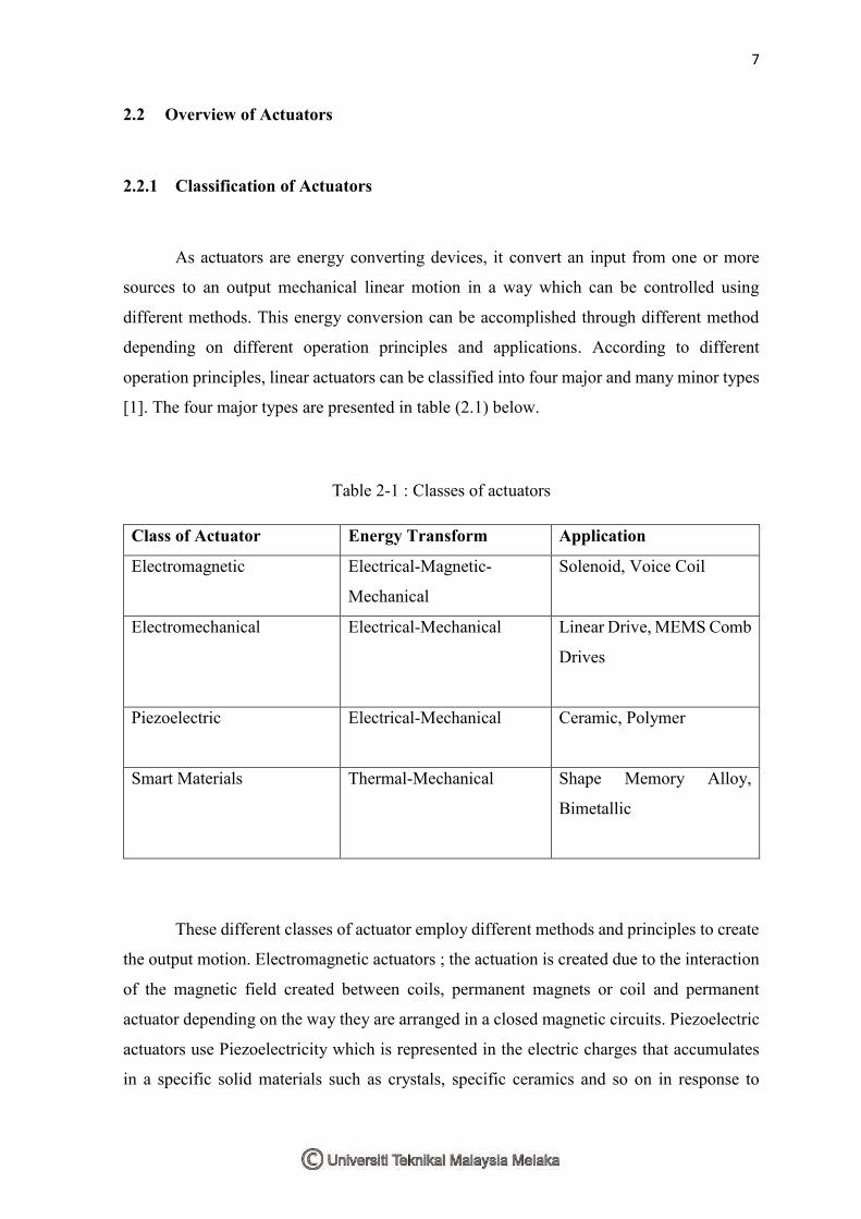
operation principles, linear actuators can be classified into four major and many minor types
[1]. The four major types are presented in table (2.1) below.
Table 2-1 : Classes of actuators
Class of Actuator Energy Transform Application
Electromagnetic Electrical-Magnetic-
Mechanical
Solenoid, Voice Coil
Electromechanical Electrical-Mechanical Linear Drive, MEMS Comb
Drives
Piezoelectric Electrical-Mechanical Ceramic, Polymer
Smart Materials Thermal-Mechanical Shape Memory Alloy,
Bimetallic
These different classes of actuator employ different methods and principles to create
the output motion. Electromagnetic actuators ; the actuation is created due to the interaction
of the magnetic field created between coils, permanent magnets or coil and permanent
actuator depending on the way they are arranged in a closed magnetic circuits. Piezoelectric
actuators use Piezoelectricity which is represented in the electric charges that accumulates
in a specific solid materials such as crystals, specific ceramics and so on in response to
8
applied mechanical stress. The mechanism of actuation or motion in the shape memory
alloys is change in the induced temperature which produces a significant shear strain when
the material temperature is above the transformation.
2.2.2 Characterization of Actuators
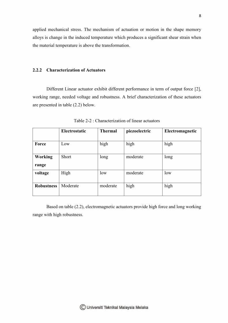
Different Linear actuator exhibit different performance in term of output force [2],
working range, needed voltage and robustness. A brief characterization of these actuators
are presented in table (2.2) below.
Table 2-2 : Characterization of linear actuators
Based on table (2.2), electromagnetic actuators provide high force and long working
range with high robustness.
Electrostatic Thermal piezoelectric Electromagnetic
Force Low high high high
Working
range
Short long moderate long
voltage High low moderate low
Robustness Moderate moderate high high
9
2.3 Electromagnetic Actuators
2.3.1 Magnetic Fields Interactions
Electromagnetic actuators in general employ magnetic field interactions to create
magnetic forces and mechanical motions. The magnetic field is generated either by electric
coil or the permanent magnet. Magnetic fields represent the fundamental mechanism by
which the energy is converted from one form to another in the electromagnetic actuators.
Basic principles describe how magnetic fields employed in actuators [3]:
1. A current-carrying wire produces a magnetic field in the area around it.
2. A current-carrying wire in the presence of a magnetic field has a force induced on it
(Motor principle).
3. A moving wire in the presence of a magnetic field has a voltage induced in it.
(Generator principle).
2.3.2 Principles of Linear Electromagnetic Actuators
Electromagnetic actuators employ the principle of using coils and magnets to convert
electrical and/or magnetic energy to mechanical energy. This conversion is accomplished
through converting voltage and to motion (force and displacement). The force which create
the mechanical motion over a specific range, is a result of the interaction of the magnetic
field generated either by current currying conductor or permanent magnets [4].
10
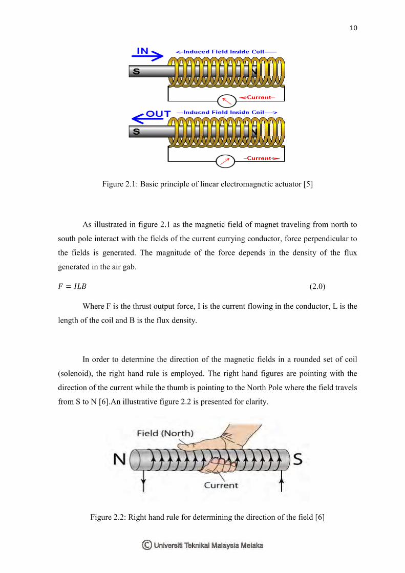
Figure 2.1: Basic principle of linear electromagnetic actuator [5]
As illustrated in figure 2.1 as the magnetic field of magnet traveling from north to
south pole interact with the fields of the current currying conductor, force perpendicular to
the fields is generated. The magnitude of the force depends in the density of the flux
generated in the air gab.
𝐹 = 𝐼𝐿𝐵 (2.0)
Where F is the thrust output force, I is the current flowing in the conductor, L is the
length of the coil and B is the flux density.
In order to determine the direction of the magnetic fields in a rounded set of coil
(solenoid), the right hand rule is employed. The right hand figures are pointing with the
direction of the current while the thumb is pointing to the North Pole where the field travels
from S to N [6].An illustrative figure 2.2 is presented for clarity.
Figure 2.2: Right hand rule for determining the direction of the field [6]
11
2.4 Electromagnetic Linear Actuators
2.4.1 Classification of Electromagnetic Linear Actuators
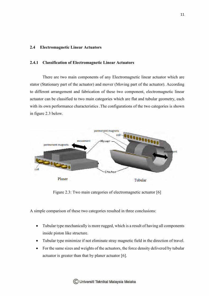
There are two main components of any Electromagnetic linear actuator which are
stator (Stationary part of the actuator) and mover (Moving part of the actuator). According
to different arrangement and fabrication of these two component, electromagnetic linear
actuator can be classified to two main categories which are flat and tubular geometry, each
with its own performance characteristics .The configurations of the two categories is shown
in figure 2.3 below.
Figure 2.3: Two main categories of electromagnetic actuator [6]
A simple comparison of these two categories resulted in three conclusions:
Tubular type mechanically is more rugged, which is a result of having all components
inside piston like structure.
Tubular type minimize if not eliminate stray magnetic field in the direction of travel.
For the same sizes and weights of the actuators, the force density delivered by tubular
actuator is greater than that by planer actuator [6].
12
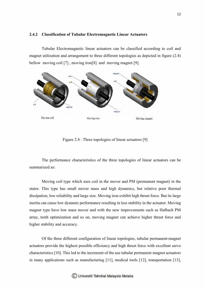
2.4.2 Classification of Tubular Electromagnetic Linear Actuators
Tubular Electromagnetic linear actuators can be classified according to coil and
magnet utilization and arrangement to three different topologies as depicted in figure (2.4)
bellow moving coil [7] , moving iron[8] and moving magnet [9].
Figure 2.4 : Three topologies of linear actuators [9]
The performance characteristics of the three topologies of linear actuators can be
summarized as:
Moving coil type which uses coil in the mover and PM (permanent magnet) in the
stator. This type has small mover mass and high dynamics, but relative poor thermal
dissipation, low reliability and large size. Moving iron exhibit high thrust force. But its large
inertia can cause low dynamic performance resulting in less stability in the actuator. Moving
magnet type have low mass mover and with the new improvements such as Halbach PM
array, teeth optimization and so on, moving magnet can achieve higher thrust force and
higher stability and accuracy.
Of the three different configuration of linear topologies, tubular permanent-magnet
actuators provide the highest possible efficiency and high thrust force with excellent servo
characteristics [10]. This led to the increment of the use tubular permanent-magnet actuators
in many applications such as manufacturing [11], medical tools [12], transportation [13],


![Linear Momentum Density in Quasistatic Electromagnetic Systems · arXiv:physics/0404139v1 [physics.ed-ph] 29 Apr 2004 Linear Momentum Density in Quasistatic Electromagnetic Systems](https://img.pdfslide.net/doc/110x75/5e00efafeeb98575462d5f23/linear-momentum-density-in-quasistatic-electromagnetic-systems-arxivphysics0404139v1.jpg)