Embed Size (px)
Citation preview
www.jimmeyerracing.com2795 SE 23rd • Lincoln City, OR 97367
Tech: 1-541-994-7717 • Order: 1-800-824-1752 • Fax: 1-541-994-2397
FORD BOLT-IN IFS INSTRUCTIONS1
FITS THE FOLLOWING FORD CARS:Mustang ‘64-73, Cougar ‘67-73, Ranchero ‘60-71, Torino ‘68-71, Cyclone ‘64-71,
Montego ‘68-71, Mavrick ‘70-77, Falcon ‘60-70, Fairlane ‘60-70, Comet ‘60-67 & ‘71-77
FRONT VIEW
BOTTOM VIEW
Upper A-arm features a L & R threaded adjuster for easy alignment
Upper shock bracket features about 3” of adjustable stance
New lower A-arm bracket bolts to stock holes
Both sides of sway bar bolt to stock holes on frame
Bolts to original front strut rod holes
Removable steering arms
MADE IN USAby American craftsman from
top quality US materials
Lower A-arm holes feature 3/4” dia. shaft & bronze bushings
Lower balljoint comes pressed in
www.jimmeyerracing.com2795 SE 23rd • Lincoln City, OR 97367
Tech: 1-541-994-7717 • Order: 1-800-824-1752 • Fax: 1-541-994-2397
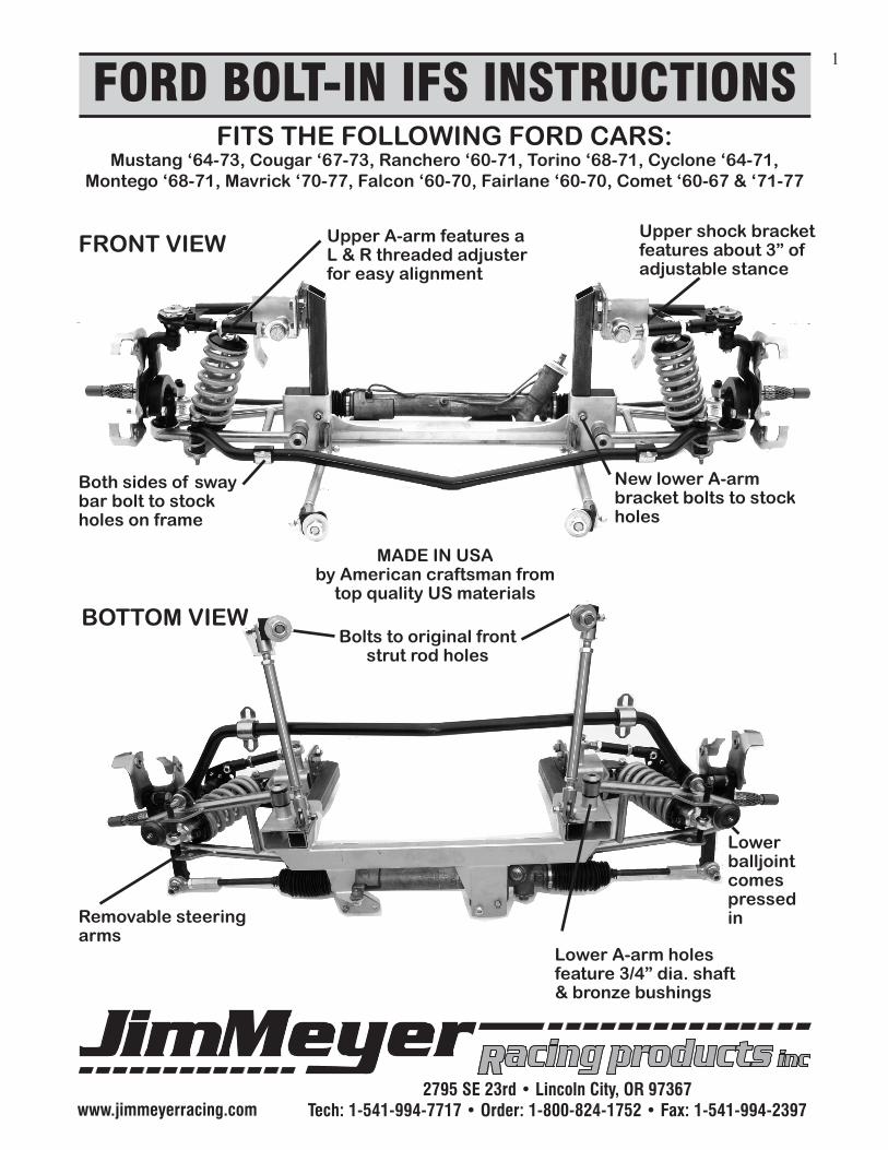
IFS Torque Specs2
All specs are in foot pounds = ft. lbs.Torque specs common to both sides
FRONT VIEW
BOTTOM VIEW
Upper balljoint nut 60 ft. lbs.
Lower balljoint nut 70 ft. lbs.
Upper & Lower 1/2” shock mount bolts 50 ft. lbs.
End caps 10 ft. lbs.
3/4” strut rod hole 70 ft. lbs.
Upper A-arm 3/4” pivot bolts 60 ft. lbs.
Top 2 holes 1/2” 50 ft. lbs.Bottom 2 3/8” 30 ft. lbs.
Upper tower
Looking at the up-per A-arm balljoint, torque the 4 - 1/4” 20 ft. lbs.
Antisway bar to frame brackets 3/8” 30 ft. lbs.
Forward support tubes 3/8” 30 ft. lbs.
R/P mounting bolts 5/16”, 3/8” or 10mm30 ft. lbs. 1/2”-50 ft. lbs.
1 - 1/2” - 50 ft. lbs.1 - 3/8” - 30 ft. lbs.
Cross shaft set-screw is installed in bottom of cross-member 5/16” 10 ft. lbs. both sides
Tie rod ends - both sides 1/2” 50 ft. lbs.
www.jimmeyerracing.com2795 SE 23rd • Lincoln City, OR 97367
Tech: 1-541-994-7717 • Order: 1-800-824-1752 • Fax: 1-541-994-2397
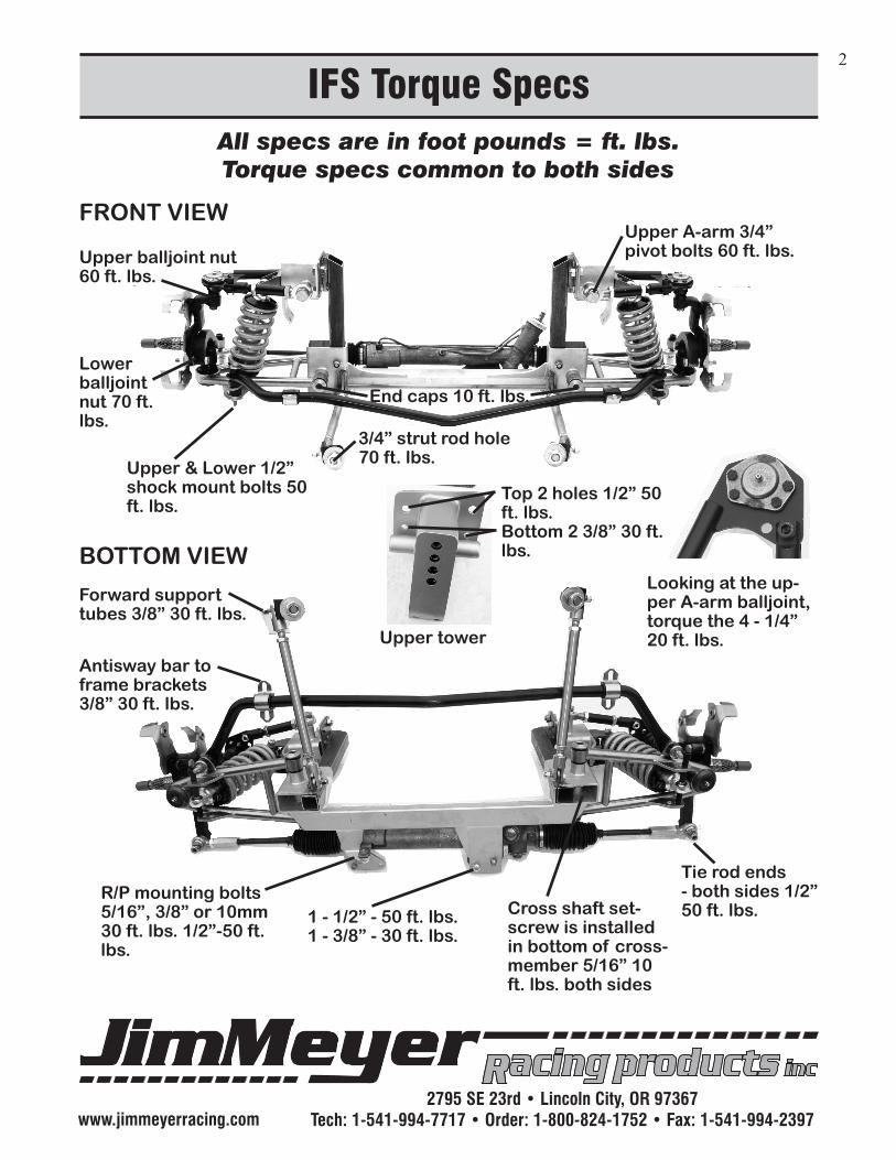
Parts Inventory Lists & Replacement Parts3
1st thing to do is read over the entire instructions
Quantity FastenerSize Fastener Location 4 1/2NCx1-1/4”Gr8HexBolt 4 1/2”SAEF436Struct.Washer UpperControl 4 1/2NCNylockNut Armand 8 3/8NCx1”Gr8HexBolt ShockTower 8 3/8NCNylockNut 4 3/4NFx2”Gr8SpecialPivotBolt 2 3/4”SphericalRodEnd Upper 2 3/4”Sph.RodEndLeftHandThread Control 2 3/4”x1/2”Clevis Arm 4 3/4”JamNutGr5 2 3/4”JamNutGr5LeftHandThread 2 1/2NCx1-1/4”SocketCapScrew 4 1/2”AN960Washer 2 1/2NCThinNylockNut 8 1/4NCx1”HexBolt 8 1/4NCLockNut Upper 2 UrethaneBoot Ball 2 CastleNut Joint 2 CotterPin 4 ShimWashers
4 1/2NCx1-1/4”SocketCapScrew 4 1/2”Ext.ToothLockWasher Shock 2 1/2NCx2-1/4”Gr8HexBolt Mount 4 1/2”SAEEx.ThickWasher 2 1/2NC4-1/2”SockCapScrew 4 1/2NCThinNylockNut 4 ShockSpacers
2 PivotShaft 8 UrethaneBushing Lower 4 3/4”StainlessAN960-LThrustWasher Control 4 AluminumPivotCaps Arm 4 5/16NFx3/4”FlatHeadSocketCapScrew
2 UrethaneBoot 2 CastleNut Lower 2 CotterPinSpindleAssembly Ball 2 5/8NFx1”Gr8HexBolt Joint 2 5/8”Int.ToothLockWasher 2 1/2NFx3-1/2”Gr8HexBolt 2 1/2NFx2-3/4”Gr8HexBolt 4 1/2”SAEEx.ThickWasher 4 1/2NFNylockNut 2 SpindleNut 2 SpindleWasher 2 CotterPin
1964-73 Mustang Hardware KitAlso Fits: Comet ‘60-67 & ‘71-77, Cougar ‘67-73, Cyclone ‘64-71, Fairlane ‘66-71, Falcon ‘60-70,
Mavrick ‘70-77, Montego ‘68-71, Ranchero ‘60-71, Torino ‘68-73Quantity FastenerSize Fastener Location
2 1/2NFx3”Gr8HexBolt 2 1/2NFNylockNut Crossmember 4 3/4”x3/8”Clevis 4 3/4”JamNutGr5 Crossmember 4 3/8NCx1-1/2”Gr8HexBolt Support 8 3/8AN960Washer Tubes 4 3/8NCNylockNut 2 “L”Bracket 2 3/4NFx1-3/4”Gr8HexBolt 2 AluminumShoulderedBushings 2 3/4”USSWasher 2 3/4NFThinNylockNut 2 1”UrethaneBushingandSaddleClamp 2 3/8NCNylockNut Front 2 3/8NCx4”Gr8HexBolt Anti-Sway 6 UrethaneBushing Bar 4 BushingWasher
1 1/2NCx1-3/4”Gr8HexBolt 2 1/2”SAEF436Struct.Washer 1 1/2NCThinNylockNut Rack& 2 3/8NCx1-1/4”Gr8HexBolt Pinion 1 3/8NCx1-3/4”Gr8HexBolt Power 6 3/8”SAEF436Struct.Washer Steering 3 3/8NCNylockNut 1 10mm-1.5x25 1 10mmSplitLockWasher
2 5/16NCx1”Gr8HexBolt 2 5/16NCx1-1/2”Gr8HexBolt Manual 8 5/16”SAEF436Struct.Washer R&P 8 5/16NCNylockNut
Spindle67-72ChevelleDiscBrakeRotor67-72Chevelle11”(8200) ReplacementCaliper67-72Chevelle(4059/60) PartsLowerBallJoint67-72Chevelle(5103)UpperBallJoint67-72Chevelle(5208)Coil-overShock9-1/2”-10”RideHeightQA1(3855B)CoilSpring2-1/2”IDx7”x650#RackandPinionPower85-92BuickElectra(RP5279)17mmDDManualFlamingRiverOmni(FR1507-2-5)9/16”x26Spline
www.jimmeyerracing.com2795 SE 23rd • Lincoln City, OR 97367
Tech: 1-541-994-7717 • Order: 1-800-824-1752 • Fax: 1-541-994-2397
Drill 8 Holes & Install Upper Tower4
2
3
1
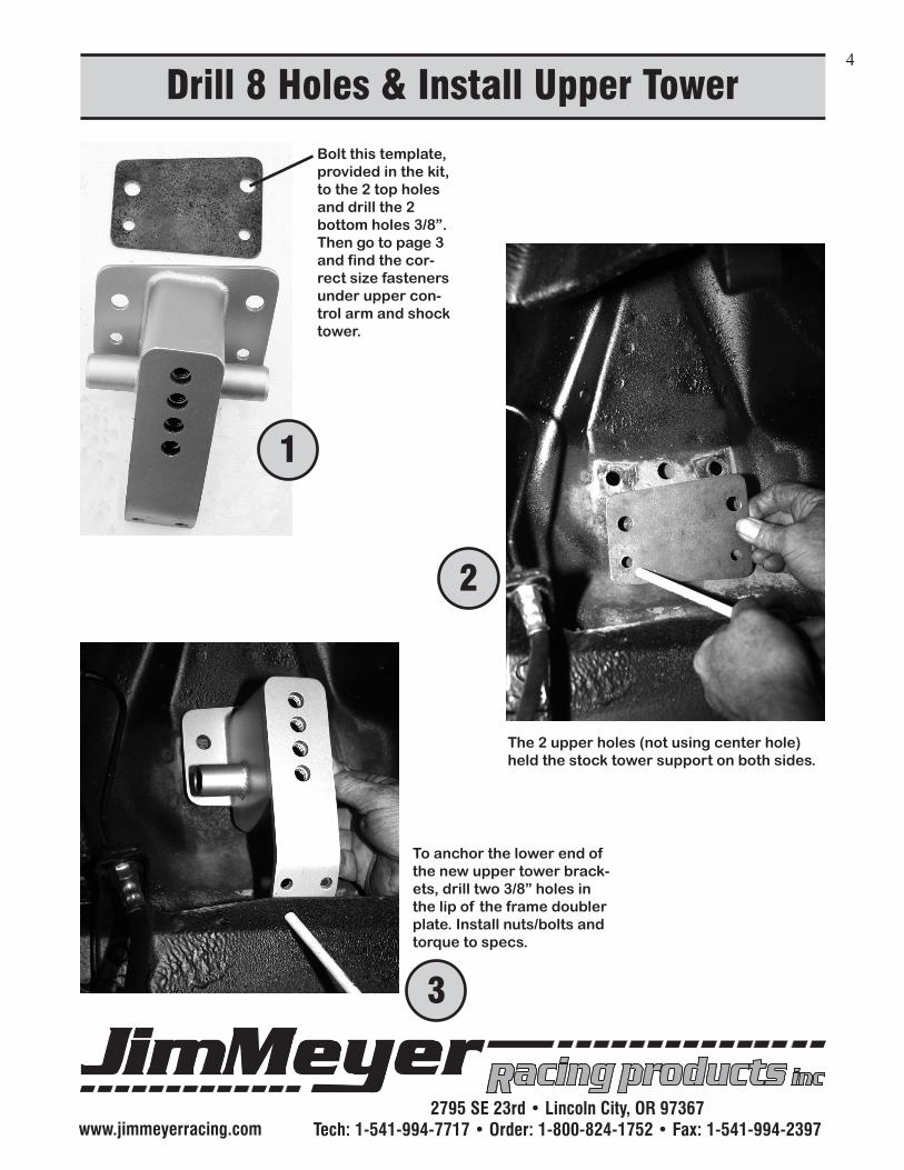
Bolt this template, provided in the kit, to the 2 top holes and drill the 2 bottom holes 3/8”. Then go to page 3 and find the cor-rect size fasteners under upper con-trol arm and shock tower.
The 2 upper holes (not using center hole) held the stock tower support on both sides.
To anchor the lower end of the new upper tower brack-ets, drill two 3/8” holes in the lip of the frame doubler plate. Install nuts/bolts and torque to specs.
www.jimmeyerracing.com2795 SE 23rd • Lincoln City, OR 97367
Tech: 1-541-994-7717 • Order: 1-800-824-1752 • Fax: 1-541-994-2397
Install Upper A-arm and Shock Bracket5
7
4
5
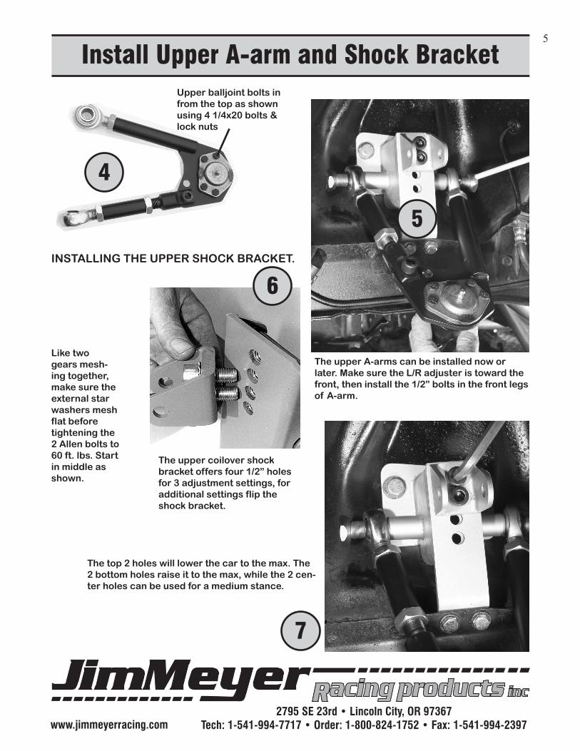
Upper balljoint bolts in from the top as shown using 4 1/4x20 bolts & lock nuts
INSTALLING THE UPPER SHOCK BRACKET.
6
Like two gears mesh-ing together, make sure the external star washers mesh flat before tightening the 2 Allen bolts to 60 ft. lbs. Start in middle as shown.
The upper A-arms can be installed now or later. Make sure the L/R adjuster is toward the front, then install the 1/2” bolts in the front legs of A-arm.
The top 2 holes will lower the car to the max. The 2 bottom holes raise it to the max, while the 2 cen-ter holes can be used for a medium stance.
The upper coilover shock bracket offers four 1/2” holes for 3 adjustment settings, for additional settings flip the shock bracket.
www.jimmeyerracing.com2795 SE 23rd • Lincoln City, OR 97367
Tech: 1-541-994-7717 • Order: 1-800-824-1752 • Fax: 1-541-994-2397
Lower Crossmember & Support Rods6
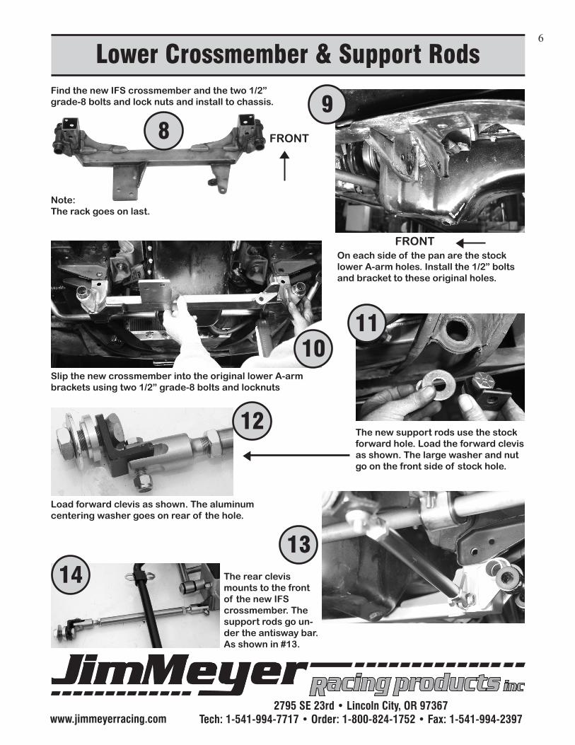
Find the new IFS crossmember and the two 1/2” grade-8 bolts and lock nuts and install to chassis.
Note:The rack goes on last.
FRONT
On each side of the pan are the stock lower A-arm holes. Install the 1/2” bolts and bracket to these original holes.
FRONT
Slip the new crossmember into the original lower A-arm brackets using two 1/2” grade-8 bolts and locknuts
The new support rods use the stock forward hole. Load the forward clevis as shown. The large washer and nut go on the front side of stock hole.
89
1011
12
1314 The rear clevis
mounts to the front of the new IFS crossmember. The support rods go un-der the antisway bar. As shown in #13.
Load forward clevis as shown. The aluminum centering washer goes on rear of the hole.
www.jimmeyerracing.com2795 SE 23rd • Lincoln City, OR 97367
Tech: 1-541-994-7717 • Order: 1-800-824-1752 • Fax: 1-541-994-2397
Installing the Lower A-arms7
FRONT
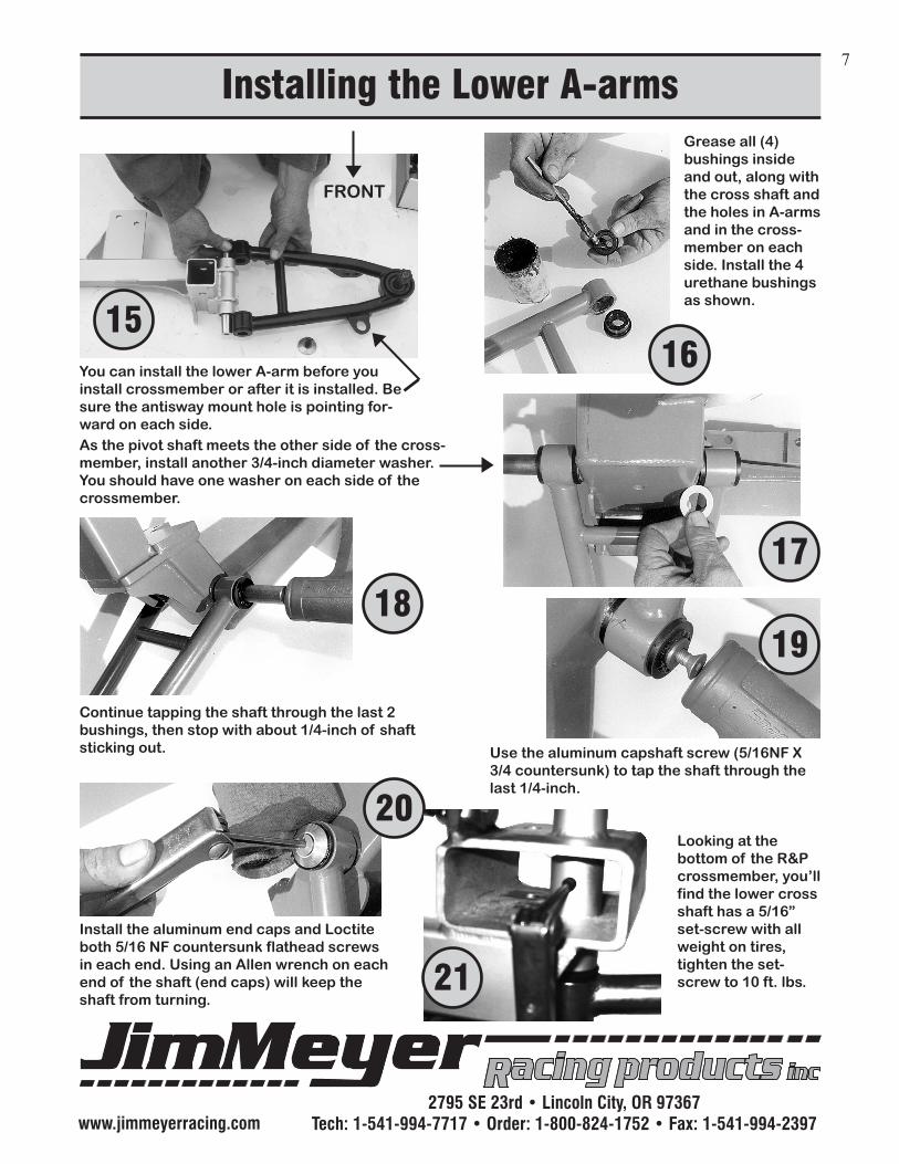
15You can install the lower A-arm before you install crossmember or after it is installed. Be sure the antisway mount hole is pointing for-ward on each side.
Grease all (4) bushings inside and out, along with the cross shaft and the holes in A-arms and in the cross-member on each side. Install the 4 urethane bushings as shown.
16
As the pivot shaft meets the other side of the cross-member, install another 3/4-inch diameter washer. You should have one washer on each side of the crossmember.
Continue tapping the shaft through the last 2 bushings, then stop with about 1/4-inch of shaft sticking out.
Install the aluminum end caps and Loctite both 5/16 NF countersunk flathead screws in each end. Using an Allen wrench on each end of the shaft (end caps) will keep the shaft from turning.
1817
19
20
Use the aluminum capshaft screw (5/16NF X 3/4 countersunk) to tap the shaft through the last 1/4-inch.
Looking at the bottom of the R&P crossmember, you’ll find the lower cross shaft has a 5/16” set-screw with all weight on tires, tighten the set-screw to 10 ft. lbs.
21
www.jimmeyerracing.com2795 SE 23rd • Lincoln City, OR 97367
Tech: 1-541-994-7717 • Order: 1-800-824-1752 • Fax: 1-541-994-2397
Mounting the Front Coilover Shocks8
24
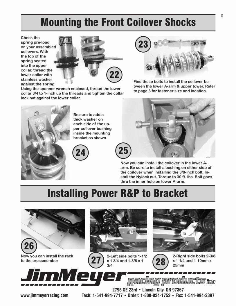
Check thespring pre-loadon your assembledcoilovers. Withthe top of thespring seatedinto the uppercollar, thread thelower collar withstainless washeragainst the spring.Using the spanner wrench enclosed, thread the lowercollar 3/4 to 1-inch up the threads and tighten the collarlock nut against the lower collar.
22
23
Find these bolts to install the coilover be-tween the lower A-arm & upper tower. Refer to page 3 for fastener size and location.
27 28
Be sure to add a thick washer on each side of the up-per coilover bushing inside the mounting bracket as shown.
Now you can install the coilover in the lower A-arm. Be sure to install a bushing on either side of the coilover when installing the 3/8-inch bolt. In-stall the Nylock nut. Torque to 30 ft. lbs. Bolt goes thru the inner hole on lower A-arm.
Installing Power R&P to Bracket
25
Now you can install the rack to the crossmember
262-Left side bolts 1-1/2 x 1 3/4 and 1-3/8 x 1 3/4
2-Right side bolts 2-3/8 x 1 1/4 and 1-10mm x 25mm
www.jimmeyerracing.com2795 SE 23rd • Lincoln City, OR 97367
Tech: 1-541-994-7717 • Order: 1-800-824-1752 • Fax: 1-541-994-2397
Connecting R & P to Steering Arms - con’t9
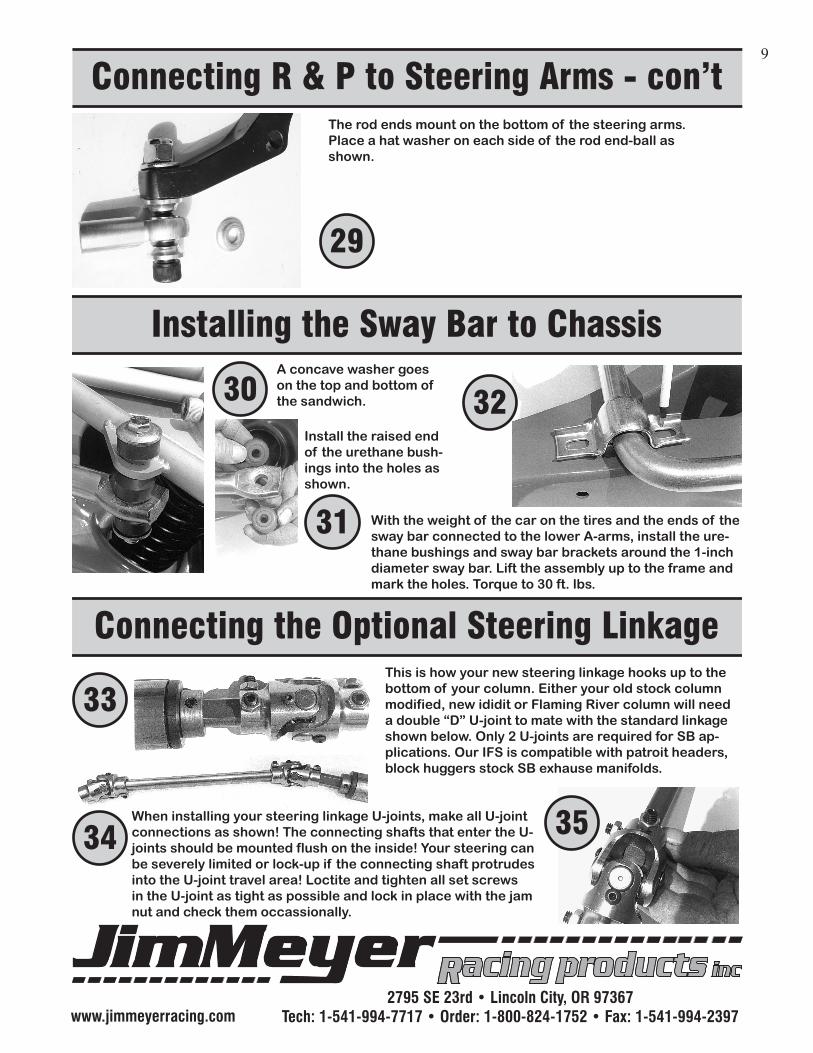
The rod ends mount on the bottom of the steering arms. Place a hat washer on each side of the rod end-ball as shown.
With the weight of the car on the tires and the ends of the sway bar connected to the lower A-arms, install the ure-thane bushings and sway bar brackets around the 1-inch diameter sway bar. Lift the assembly up to the frame and mark the holes. Torque to 30 ft. lbs.
30
31
33
35
Installing the Sway Bar to Chassis
Connecting the Optional Steering Linkage
29
A concave washer goes on the top and bottom of the sandwich.
Install the raised end of the urethane bush-ings into the holes as shown.
When installing your steering linkage U-joints, make all U-joint connections as shown! The connecting shafts that enter the U-joints should be mounted flush on the inside! Your steering can be severely limited or lock-up if the connecting shaft protrudes into the U-joint travel area! Loctite and tighten all set screws in the U-joint as tight as possible and lock in place with the jam nut and check them occassionally.
This is how your new steering linkage hooks up to the bottom of your column. Either your old stock column modified, new ididit or Flaming River column will need a double “D” U-joint to mate with the standard linkage shown below. Only 2 U-joints are required for SB ap-plications. Our IFS is compatible with patroit headers, block huggers stock SB exhause manifolds.
34
32
www.jimmeyerracing.com2795 SE 23rd • Lincoln City, OR 97367
Tech: 1-541-994-7717 • Order: 1-800-824-1752 • Fax: 1-541-994-2397
Connecting the Brake System10
38
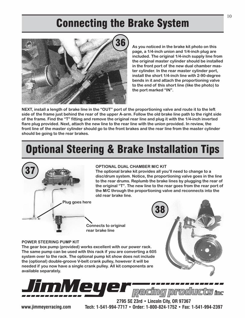
Optional Steering & Brake Installation TipsOPTIONAL DUAL CHAMBER M/C KITThe optional brake kit provides all you’ll need to change to a disc/drum system. Notice, the proportioning valve goes in the line to the rear drums. Replumb the brake lines by plugging the rear of the original “T”. The new line to the rear goes from the rear port of the M/C through the proportioning valve and reconnects into the old rear brake line.
POWER STEERING PUMP KITThe gear box pump (provided) works excellent with our power rack. The same pump can be used with this rack if you are converting a 605 system over to the rack. The optional pump kit show does not include the (optional) double-groove V-belt crank pulley, however it will be needed if you now have a single crank pulley. All kit components are available separately.
37
Plug goes here
Connects to original rear brake line
As you noticed in the brake kit photo on this page, a 1/4-inch union and 1/4-inch plug are included. The original 1/4-inch supply line from the original master cylinder should be installed in the front port of the new dual chamber mas-ter cylinder. In the rear master cylinder port, install the short 1/4-inch line with 2-90-degree bends in it and attach the proportioning valve to the end of this short line (like the photo) to the port marked “IN”.
NEXT, install a length of brake line in the “OUT” port of the proportioning valve and route it to the left side of the frame just behind the rear of the upper A-arm. Follow the old brake line path to the right side of the frame. Find the “T” fitting and remove the original rear line and plug it with the 1/4-inch inverted flare plug provided. Next, attach the new line to the rear line with the union provided. In review, the front line of the master cylinder should go to the front brakes and the rear line from the master cylinder should be going to the rear brakes.
36
www.jimmeyerracing.com2795 SE 23rd • Lincoln City, OR 97367
Tech: 1-541-994-7717 • Order: 1-800-824-1752 • Fax: 1-541-994-2397
Front End Alignment11
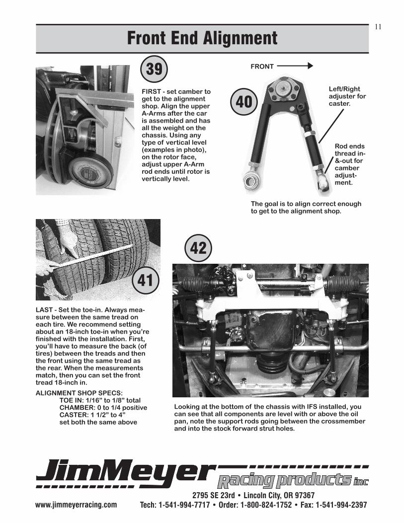
FIRST - set camber to get to the alignment shop. Align the upper A-Arms after the car is assembled and has all the weight on the chassis. Using any type of vertical level (examples in photo), on the rotor face, adjust upper A-Arm rod ends until rotor is vertically level.
LAST - Set the toe-in. Always mea-sure between the same tread on each tire. We recommend setting about an 18-inch toe-in when you’re finished with the installation. First, you’ll have to measure the back (of tires) between the treads and then the front using the same tread as the rear. When the measurements match, then you can set the front tread 18-inch in.
ALIGNMENT SHOP SPECS: TOE IN: 1/16” to 1/8” total CHAMBER: 0 to 1/4 positive CASTER: 1 1/2” to 4” set both the same above
Looking at the bottom of the chassis with IFS installed, you can see that all components are level with or above the oil pan, note the support rods going between the crossmember and into the stock forward strut holes.
FRONT 39
41
42
40Left/Right adjuster for caster.
Rod ends thread in-&-out for camber adjust-ment.
The goal is to align correct enough to get to the alignment shop.
www.jimmeyerracing.com2795 SE 23rd • Lincoln City, OR 97367
Tech: 1-541-994-7717 • Order: 1-800-824-1752 • Fax: 1-541-994-2397
JIM MEYER RACING PRODUCTSWARNING: Installation of any component or kit should only be performed by persons experienced in the installation and proper operation of SUSPENSION SYSTEMS. It is also the responsibility of the person installing any SUSPENSION SYSTEM or kit to de-termine the suitability of the component or kit for that particular application.
DISCLAIMER OF WARRANTY
Purchasersrecognizeandunderstandthatsuspensionsystemsandequipment,andallparts,inventoryandservicesmanufacturedand/orbyJIMMEYERRACINGPRODUCTSareexposedtomanyandvariedconditionsduetothemannerinwhichtheyareinstalledandused.PurchasersandJimMeyerRacingProductsconsciouslydesiretomaketheirownbargain,irrespectiveofanycourtdecisionandpurchasersagreeupongoodfaithandinconsid-erationforbeingallowedtopurchasefromJimMeyerRacingProductssaidpartorservices.Purchasersexpresslyacknowledge and understand that Jim Meyer Racing Products does not make any affirmation of fact or promise to purchaser,whichrelatedtosaidparts,inventory,orservicesthatbecomespartofthebasisofthebargainbetweenJimMeyerRacingProductsandpurchasers.NordoesJimMeyerRacingProductsmake,orcausetobemadetopurchaseranydescriptionofthegoodssoldtopurchaser,nordoesJimMeyerRacingProductsmakeorcausetobemade, a part of the basis of the bargain with purchasers, any description of affirmation of fact concerning any sample orsuspensionsystems,andequipmentinventoryorservice. AsfurtherconsiderationforpurchasersusingJimMeyerRacingProductssuspensionsystemsandequipmentanyandallinventoryandservices,purchasersacknowledgethatduetothedifferingconditionsandcircumstancesunderwhichallequipmentandpartsareinstalledandused,purchasersarenotrelyingonJimMeyerRacingProductsskill or judgement to select or furnish the proper part or equipment. Purchasers expressly affirm they are relying upontheirownskillorjudgementtoselectandpurchasesuitablegoods. JimMeyerRacingProductsmakesnowarrantieswhatsoever,expressedorimplied,oralorwritten,topur-chasers.Thereisnowarrantyofmerchantabilitymadetopurchasers.JimMeyerRacingProductsfurtherexcludesanyimplied warranty of fitness with respect to suspension system and equipment, any and all inventory and service. ItisexpresslyunderstoodandagreedbetweenpurchasersandJimMeyerRacingProductsthatasapartofbargainbetweenJimMeyerRacingProductsandpurchaser,andinconsiderationofdoingbusinesswitheachother,allpurchaserstake,selectandpurchasesaidsuspensionsystem,equipment,anyandallinventory,orservicesfromJimMeyerRacingProducts“asis”and“withallfaults”andJimMeyerRacingProductsshallalwaysprovidepurchaserswithafullandcompleteopportunitytoexamine,atpurchasersleisureandconvenience,anysuspensionsystemandequipment,anyandallinventory,orserviceswhenpurchasingorcontemplatingpurchasingfromJimMeyerRacingProducts. If, and in the event that purchasers expressly or impliedly cause representations, or statements or affirma-tionsoffactcontrarytothisdisclaimerofallwarranties,expressedorimplied,thenpurchasersagreetoindemnityandholdharmlessJimMeyerRacingProductsintheeventofanyclaim,demand,orlegalactionagainstJimMeyerRacingProductsbyanypurchaser. Purchasers understand and agree that no officer, director, employee, or salesman of Jim Meyer Racing Prod-uctshasanyauthoritytomakeanystatementcontrarytothetermsofthisagreement.Onthecontrary,JimMeyerRacingProductsdisavowsanystatementcontrarytowhatishereinabovewritten.