Embed Size (px)
Citation preview
An Introduction to Antenna Test Ranges, Measurements andInstrumentation
The basic principles of antenna test and measurement are discussed along with an introductionto various range geometries, and instrumentation.
ByJeffrey A. Fordham
Microwave Instrumentation Technologies, LLC.
IntroductionBy definition, all of today's wireless communication systems contain one key element, an antenna of some form. This antennaserves as the transducer between the controlled energy residing within the system and the radiated energy existing in freespace. In designing wireless systems, engineers must choose an antenna that meets the system's requirements to firmly closethe link between the remote points of the communications system. While the forms that antennas can take on to meet thesesystem requirements for communications systems are nearly limitless, most antennas can be specified by a common set ofperformance metrics.
Antenna Performance MetricsIn order to satisfy the system requirements and choose a suitable antenna, system engineers must evaluate an antenna'sperformance. Typical metrics used in evaluating an antenna includes the input impedance, polarization, radiation efficiency,directivity, gain and radiation pattern.
Input ImpedanceInput impedance is the parameter which relates the antenna to its transmission line. It is of primary importance in determiningthe transfer of power from the transmission line to the antenna and vice versa. The impedance match between the antenna andthe transmission line is usually expressed in terms of the standing wave ratio (SWR) or the reflection coefficient of the antennawhen connected to a transmission line of a given impedance. The reflection coefficient expressed in decibels is called returnloss.
PolarizationThe polarization of an antenna is defined as the polarization of the electromagnetic wave radiated by the antenna along avector originating at the antenna and pointed along the primary direction of propagation. The polarization state of the wave isdescribed by the shape and orientation of an ellipse formed by tracing the extremity of the electromagnetic field vector versustime. Although all antennas are elliptically polarized, most antennas are specified by the ideal polarization conditions ofcircular or linear polarization.
The ratio of the major axis to the minor axis of the polarization ellipse defines the magnitude of the axial ratio. The tilt angledescribes the orientation of the ellipse in space. The sense of polarization is determined by observing the direction of rotationof the electric field vector from a point behind the source. Right-hand and left-hand polarizations correspond to clockwise andcounterclockwise rotation respectively.
DirectivityIt is convenient to express the directive properties of an antenna in terms of the distribution in space of the power radiated bythe antenna. The directivity is defined as 4π times the ratio of the maximum radiation intensity (power radiated per unit solidangle) to the total power radiated by the antenna. The directivity of an antenna is independent of its radiation efficiency andits impedance match to the connected transmission line.
Gain
The gain, or power gain, is a measure of the ability to concentrate in a particular direction the net power accepted by theantenna from the connected transmitter. When the direction is not specified, the gain is usually taken to be its maximum value.Antenna gain is independent of reflection losses resulting from impedance mismatch.
Radiation EfficiencyThe radiation efficiency of an antenna is the ratio of the power radiated by the antenna to the net power accepted at its inputterminals. It may also be expressed as the ratio of the maximum gain to the directivity.
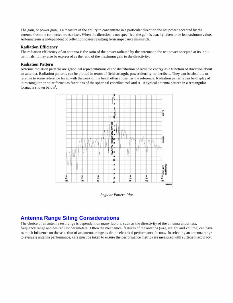
Radiation PatternAntenna radiation patterns are graphical representations of the distribution of radiated energy as a function of direction aboutan antenna. Radiation patterns can be plotted in terms of field strength, power density, or decibels. They can be absolute orrelative to some reference level, with the peak of the beam often chosen as the reference. Radiation patterns can be displayedin rectangular or polar format as functions of the spherical coordinates θ and φ. A typical antenna pattern in a rectangularformat is shown below1.
Regular Pattern Plot
Antenna Range Siting ConsiderationsThe choice of an antenna test range is dependent on many factors, such as the directivity of the antenna under test,frequency range and desired test parameters. Often the mechanical features of the antenna (size, weight and volume) can haveas much influence on the selection of an antenna range as do the electrical performance factors. In selecting an antenna rangeto evaluate antenna performance, care must be taken to ensure the performance metrics are measured with sufficient accuracy.
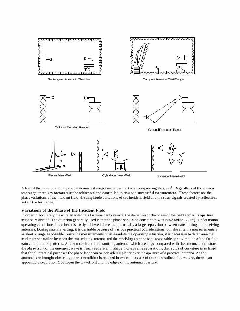
A few of the more commonly used antenna test ranges are shown in the accompanying diagram2. Regardless of the chosentest range, three key factors must be addressed and controlled to ensure a successful measurement. These factors are thephase variations of the incident field, the amplitude variations of the incident field and the stray signals created by reflectionswithin the test range.
Variations of the Phase of the Incident FieldIn order to accurately measure an antenna’s far zone performance, the deviation of the phase of the field across its aperturemust be restricted. The criterion generally used is that the phase should be constant to within π/8 radian (22.5°). Under normaloperating conditions this criteria is easily achieved since there is usually a large separation between transmitting and receivingantennas. During antenna testing, it is desirable because of various practical considerations to make antenna measurements atas short a range as possible. Since the measurements must simulate the operating situation, it is necessary to determine theminimum separation between the transmitting antenna and the receiving antenna for a reasonable approximation of the far fieldgain and radiation patterns. At distances from a transmitting antenna, which are large compared with the antenna dimensions,the phase front of the emergent wave is nearly spherical in shape. For extreme separations, the radius of curvature is so largethat for all practical purposes the phase front can be considered planar over the aperture of a practical antenna. As theantennas are brought closer together, a condition is reached in which, because of the short radius of curvature, there is anappreciable separation ∆ between the wavefront and the edges of the antenna aperture.
Rectangular Anechoic Chamber Compact Antenna Test Range
Outdoor Elevated RangeGround Reflection Range
Planar Near-Field Cylindrical Near-Field Spherical Near-Field
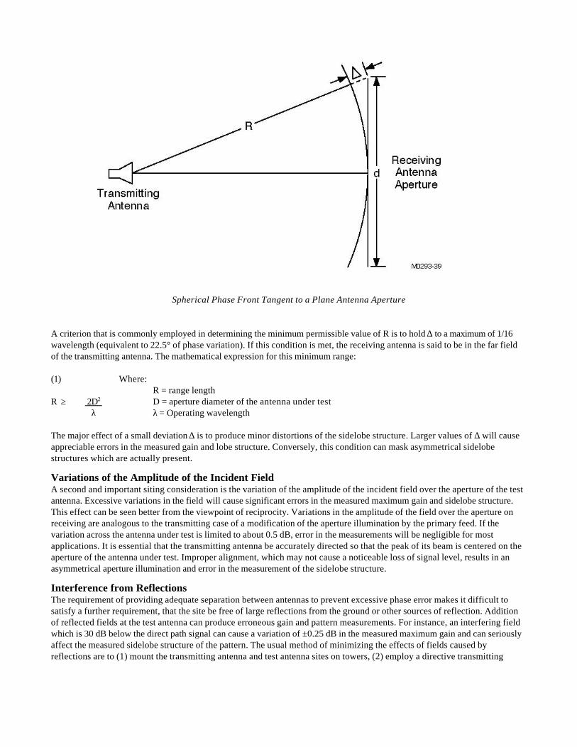
Spherical Phase Front Tangent to a Plane Antenna Aperture
A criterion that is commonly employed in determining the minimum permissible value of R is to hold ∆ to a maximum of 1/16wavelength (equivalent to 22.5° of phase variation). If this condition is met, the receiving antenna is said to be in the far fieldof the transmitting antenna. The mathematical expression for this minimum range:
(1) Where:R = range length
R ≥ 2D2 D = aperture diameter of the antenna under test λ λ = Operating wavelength
The major effect of a small deviation ∆ is to produce minor distortions of the sidelobe structure. Larger values of ∆ will causeappreciable errors in the measured gain and lobe structure. Conversely, this condition can mask asymmetrical sidelobestructures which are actually present.
Variations of the Amplitude of the Incident FieldA second and important siting consideration is the variation of the amplitude of the incident field over the aperture of the testantenna. Excessive variations in the field will cause significant errors in the measured maximum gain and sidelobe structure.This effect can be seen better from the viewpoint of reciprocity. Variations in the amplitude of the field over the aperture onreceiving are analogous to the transmitting case of a modification of the aperture illumination by the primary feed. If thevariation across the antenna under test is limited to about 0.5 dB, error in the measurements will be negligible for mostapplications. It is essential that the transmitting antenna be accurately directed so that the peak of its beam is centered on theaperture of the antenna under test. Improper alignment, which may not cause a noticeable loss of signal level, results in anasymmetrical aperture illumination and error in the measurement of the sidelobe structure.
Interference from ReflectionsThe requirement of providing adequate separation between antennas to prevent excessive phase error makes it difficult tosatisfy a further requirement, that the site be free of large reflections from the ground or other sources of reflection. Additionof reflected fields at the test antenna can produce erroneous gain and pattern measurements. For instance, an interfering fieldwhich is 30 dB below the direct path signal can cause a variation of ±0.25 dB in the measured maximum gain and can seriouslyaffect the measured sidelobe structure of the pattern. The usual method of minimizing the effects of fields caused byreflections are to (1) mount the transmitting antenna and test antenna sites on towers, (2) employ a directive transmitting
antenna, (3) avoid smooth surfaces which are oriented so that they produce direct reflection into the test antenna, and (4)erect screens or baffles to intercept the reflected wave near the reflection point.
An alternate procedure is to locate the transmitting and receiving antennas over a flat range and to take into account thespecular reflection from the ground in making measurements. The heights of the antenna under test and the transmittingantenna are adjusted for a maximum of the interference pattern between the direct and ground reflected wave. Generally, it ismore convenient to mount the test positioner and antenna on a fixed height tower or building and vary the height of thetransmitting antenna. This can be accomplished with the transmitting antenna mounted to a motor driven elevator/carriageassembly that can travel up and down a tower.
In cases where the antenna range length is reasonably short, the entire range can be housed indoors in an anechoic chamber.An indoor far-field anechoic chamber has the same basic design criteria as an outdoor range except that the surfaces of theroom are covered with RF absorbing material. This absorber is designed to reduce reflected signal over its design frequencyrange. Testing indoors offers many advantages to conventional outdoor ranges including improved security, avoidingunwanted surveillance and improved productivity due to less time lost because of weather and other environmentally relatedfactors. The advantages of testing indoors are primarily responsible for the trend toward more advanced test ranges such asthe compact range and near-field ranges.
Amplitude Variation - Elevated RangesVariations in the amplitude of the field incident over a test aperture must also be restricted for accurate far-zone measurements.For range geometries employing comparatively large transmitting and test tower heights (i.e., elevated range geometries), it isadvisable to restrict amplitude taper to the order of 1/4 dB or less by using the following criterion:
Where:(2) dt = transmitting antenna diameter
λ = wavelengthdt ≤ λR R = range length
4D D = maximum test aperture dimension
From the viewpoint of suppressing range surface reflections, it is also desirable to maintain the test height H, greater than orequal to 6D. If one must, for practical reasons, employ test heights less than approximately 4D, the ground-reflectiontechnique should be considered.
Ground-Reflection Antenna Test RangesGround-reflection antenna range geometries are often advantageous when the test situation involves low directivities andhigh accuracy requirements or when practical test heights are less than approximately four times the maximum verticaldimension of the test aperture. In this technique specular reflection from the range surface is caused to create constructiveinterference with the direct-path energy in the region of the test aperture, such that the peak of the first interference patternlobe is centered on the test aperture. Four basic criteria are applicable to ground-reflection range geometries:
(3)R ≥ 2D2
λ(4)
hr ≥ 3.3D Vertical-plane amplitudetaper 1/4 dB
(5)ht = λR Peak of first interference
4hr lobe at h r(6)
dt ≤ λR Horizontal-plane amplitude 4D taper ≤ 1/4 dB
In these expressions:R = range lengthD = test aperture diameterλ = wavelengthhr = height of the center of the
test apertureht = height of the center of the
transmitting antennadt = transmitting antenna diameter
Compact Antenna Test RangesCompact ranges are an excellent alternative to traditional far-field ranges. Any testing that can be accomplished on a far-fieldrange can be accomplished on a compact antenna test range. This method of testing allows an operator to employ an indooranechoic test chamber at a reasonable cost and avoid the problems associated with weather and security often encounteredwhen using an outdoor test range. In a research and development situation, the small size of a compact range allows it to belocated convenient to the design engineers. In a manufacturing environment, the compact range can be located near to thefinal testing and integration facilities. By placing a compact range in a shielded chamber, one can eliminate interference fromexternal sources. This last feature has become more important in the last several years as the proliferation of cell phone andwireless systems has created a background noise environment which has made antenna testing in a quiet electromagneticenvironment more difficult
The principle of operation of a compact range is based on the basic concepts of geometrical optics. Diverging spherical wavesfrom a point source located at the focal point of a paraboloidal surface are collimated into a plane wave. This plane wave isincident on the test antenna. The resultant plane wave has a very flat phase front, but the reflector-feed combinationintroduces a small (but generally acceptable) amplitude taper across the test zone.
In principle, the operation of a compact range is straightforward; however, its ultimate design, construction, and installationshould be carefully considered.
Near-Field Antenna Test RangesNear-field ranges are used where large antennas are to be tested indoors in a relatively small space. This type of range uses asmall RF probe antenna that is scanned over a surface surrounding the test antenna. Typically separation between the probeand the antenna structure is on the order of 4 to 10 wavelengths. During the measurement, near-field phase and amplitudeinformation is collected over a discrete matrix of points. This data is then transformed to the far-field using Fourier techniques.The resulting far-field data can then be displayed in the same formats as conventional far-field antenna measurements.
In addition to obtaining far-field data, Fourier analysis techniques are used to back-transform the measured electromagneticfield to the antenna's aperture to produce aperture field distribution information. This offers the ability to perform elementdiagnostics on multi-element phased arrays.
In near-field testing, the test antenna is usually aligned to the scanner’s coordinate system and then either the probe or thetest antenna is moved. In practice it is easier and more cost effective to scan the RF probe over linear axes or the test antennaover angular axes. But this does not have to be the case. There are many scanning coordinate systems possible for collectingthe near-field data. Three techniques are in common usage:
Planar Near-Field Method – With planar near-field scanning, the probe usually is scanned in X and Y linear coordinates overthe aperture of the test antenna. A large planar scanner is used to move the probe over a very accurate plane located in frontof the test antenna’s aperture. Once aligned to the scan plane, the test antenna is not moved during the collection of the near-field data. Planar near-field provides limited angular coverage of the test antenna’s field due to the truncation caused by thescanner's dimensions.
Cylindrical Near-Field Method – For this method the probe typically is scanned in one linear dimension using a single axislinear positioner. The test antenna is stepped in angle on a rotary axis oriented parallel to the linear axis. The resulting scandescribes a cylindrical surface around the test antenna. Cylindrical near-field scanning can provide complete angular coverageof the test antenna’s field in one plane. The orthogonal plane has limited angular coverage due to truncation caused by thefinite length of the linear scanner.
Spherical Near-Field Method – Spherical near-field scanning normally involves installing the test antenna on a sphericalscanning positioner. The probe antenna is normally fixed in space. The test antenna is normally scanned in one angular axisand stepped in an orthogonal angular axis. The resulting data is collected over a spherical envelope surrounding the testantenna. Full or nearly-full coverage of the test antenna’s radiating field can be evaluated with this type of near-field system.
Pulsed Antenna Measurements
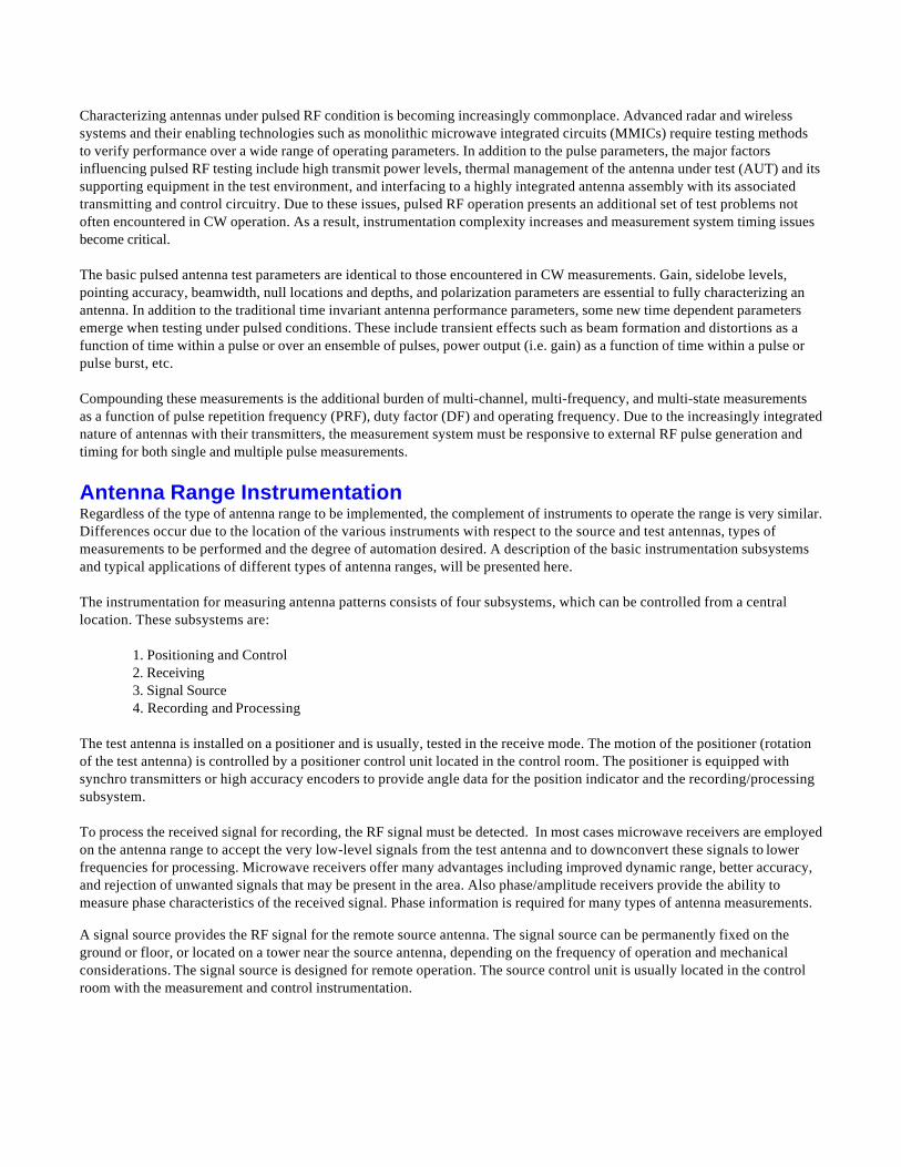
Characterizing antennas under pulsed RF condition is becoming increasingly commonplace. Advanced radar and wirelesssystems and their enabling technologies such as monolithic microwave integrated circuits (MMICs) require testing methodsto verify performance over a wide range of operating parameters. In addition to the pulse parameters, the major factorsinfluencing pulsed RF testing include high transmit power levels, thermal management of the antenna under test (AUT) and itssupporting equipment in the test environment, and interfacing to a highly integrated antenna assembly with its associatedtransmitting and control circuitry. Due to these issues, pulsed RF operation presents an additional set of test problems notoften encountered in CW operation. As a result, instrumentation complexity increases and measurement system timing issuesbecome critical.
The basic pulsed antenna test parameters are identical to those encountered in CW measurements. Gain, sidelobe levels,pointing accuracy, beamwidth, null locations and depths, and polarization parameters are essential to fully characterizing anantenna. In addition to the traditional time invariant antenna performance parameters, some new time dependent parametersemerge when testing under pulsed conditions. These include transient effects such as beam formation and distortions as afunction of time within a pulse or over an ensemble of pulses, power output (i.e. gain) as a function of time within a pulse orpulse burst, etc.
Compounding these measurements is the additional burden of multi-channel, multi-frequency, and multi-state measurementsas a function of pulse repetition frequency (PRF), duty factor (DF) and operating frequency. Due to the increasingly integratednature of antennas with their transmitters, the measurement system must be responsive to external RF pulse generation andtiming for both single and multiple pulse measurements.
Antenna Range InstrumentationRegardless of the type of antenna range to be implemented, the complement of instruments to operate the range is very similar.Differences occur due to the location of the various instruments with respect to the source and test antennas, types ofmeasurements to be performed and the degree of automation desired. A description of the basic instrumentation subsystemsand typical applications of different types of antenna ranges, will be presented here.
The instrumentation for measuring antenna patterns consists of four subsystems, which can be controlled from a centrallocation. These subsystems are:
1. Positioning and Control2. Receiving3. Signal Source4. Recording and Processing
The test antenna is installed on a positioner and is usually, tested in the receive mode. The motion of the positioner (rotationof the test antenna) is controlled by a positioner control unit located in the control room. The positioner is equipped withsynchro transmitters or high accuracy encoders to provide angle data for the position indicator and the recording/processingsubsystem.
To process the received signal for recording, the RF signal must be detected. In most cases microwave receivers are employedon the antenna range to accept the very low-level signals from the test antenna and to downconvert these signals to lowerfrequencies for processing. Microwave receivers offer many advantages including improved dynamic range, better accuracy,and rejection of unwanted signals that may be present in the area. Also phase/amplitude receivers provide the ability tomeasure phase characteristics of the received signal. Phase information is required for many types of antenna measurements.
A signal source provides the RF signal for the remote source antenna. The signal source can be permanently fixed on theground or floor, or located on a tower near the source antenna, depending on the frequency of operation and mechanicalconsiderations. The signal source is designed for remote operation. The source control unit is usually located in the controlroom with the measurement and control instrumentation.
Often, a computer subsystem is added to the instrumentation to automate the entire measurement sequence. This computersubsystem employs a standard bus interface, like the IEEE-488, to setup and monitor the individual instruments. High-speeddata busses are utilized for the measurement data to maximize data throughput and productivity.
An automated antenna measurement system offers a high degree of repeatability, speed, accuracy, and efficiency withminimum operator interaction. Data storage is conveniently handled by a variety of media including a local hard drive, floppydisk, removable drives or bulk data storage on a local area network. After data acquisition is completed, an automated systemsupports analysis of the measured data such as gain and polarization plus a wide variety of data plotting formats such asrectangular, polar, three-dimensional, and contour plots.
Typical Applications of Antenna Range Instrumentation
Outdoor Far-Field RangeIn an outdoor far-field range configuration, the test antenna is installed on the test positioner located on a tower, roof orplatform outside the instrumentation control room. The receiver front end (Local Oscillator) is usually located at the base ofthe test positioner, with the mixer connected directly to the test antenna port. This configuration requires only a single RFpath through the positioner, greatly simplifying system design. Use of the remote front end also minimizes local oscillatorpower loss to the mixer and maximum system sensitivity. An outdoor enclosure protects the local oscillator from the weatherand temperature extremes. For multi-ported antennas, simultaneous measurements can be made on all ports through the use ofmultiplexers installed in front of the mixer. The receiver front end is remotely controlled from the control console throughinterfaces with the receiver.
The test positioner axes are controlled and read out by the positioner control and readout units. A typical control systemconsists of a control unit located in the operator’s console. It is interfaced to a power amplifier unit located near the testpositioner. This configuration keeps the high power drive signals near the positioner and away from sensitive measurementinstruments while providing remote control of positioner functions from the equipment console. The position readout unit islocated in the equipment console to provide real time readout of position axes to the operator or, in the case of an automatedsystem, to the computer.
The source antenna is normally located at the opposite end of the range on a tower or other supporting structure. The signalsource is installed near the source antenna to minimize signal loss. An outdoor enclosure protects the source from theelements. For some applications a multiplexer can be used between the signal source and a dual polarized source antenna. Thisconfiguration allows simultaneous co- and cross-polarization measurements to be performed. Motorized axes to position thesource antenna’s polarization, height and boresight are controlled by a positioner control and indicator system.
The signal source and positioner axes are remotely controlled from the operator’s console via serial digital link(s). Twisted paircable, fiber optics or telephone lines can be used to interface the digital link from the source site to the control console.
One or two positioner control systems may be used on an outdoor range depending upon the length of the range and the totalnumber of axes to be controlled. On very long ranges, or in cases where the control room is not close to either positioner, itmay be advantageous to use a separate control unit for each end of the range. Also, since outdoor ranges frequently havemany axes due to the source tower axes, multiple controllers may be required to control all axes.
A block diagram of a typical outdoor range is shown below.
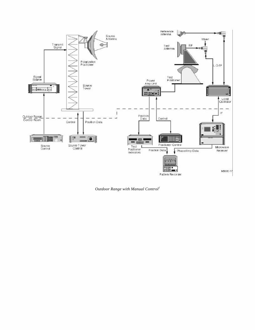
Outdoor Range with Manual Control1
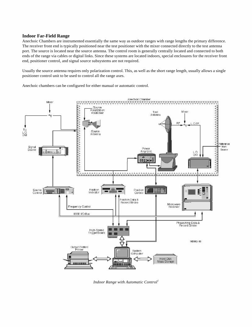
Indoor Far-Field RangeAnechoic Chambers are instrumented essentially the same way as outdoor ranges with range lengths the primary difference.The receiver front end is typically positioned near the test positioner with the mixer connected directly to the test antennaport. The source is located near the source antenna. The control room is generally centrally located and connected to bothends of the range via cables or digital links. Since these systems are located indoors, special enclosures for the receiver frontend, positioner control, and signal source subsystems are not required.
Usually the source antenna requires only polarization control. This, as well as the short range length, usually allows a singlepositioner control unit to be used to control all the range axes.
Anechoic chambers can be configured for either manual or automatic control.
Indoor Range with Automatic Control1
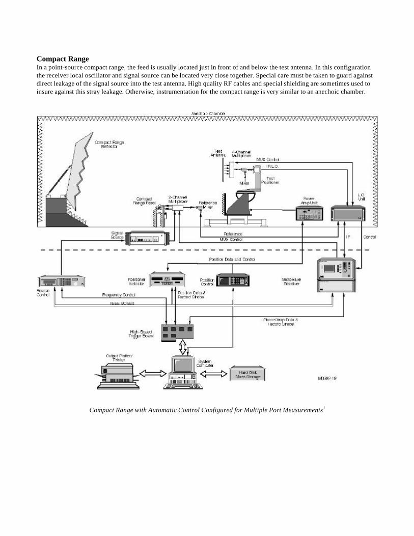
Compact RangeIn a point-source compact range, the feed is usually located just in front of and below the test antenna. In this configurationthe receiver local oscillator and signal source can be located very close together. Special care must be taken to guard againstdirect leakage of the signal source into the test antenna. High quality RF cables and special shielding are sometimes used toinsure against this stray leakage. Otherwise, instrumentation for the compact range is very similar to an anechoic chamber.
Compact Range with Automatic Control Configured for Multiple Port Measurements1
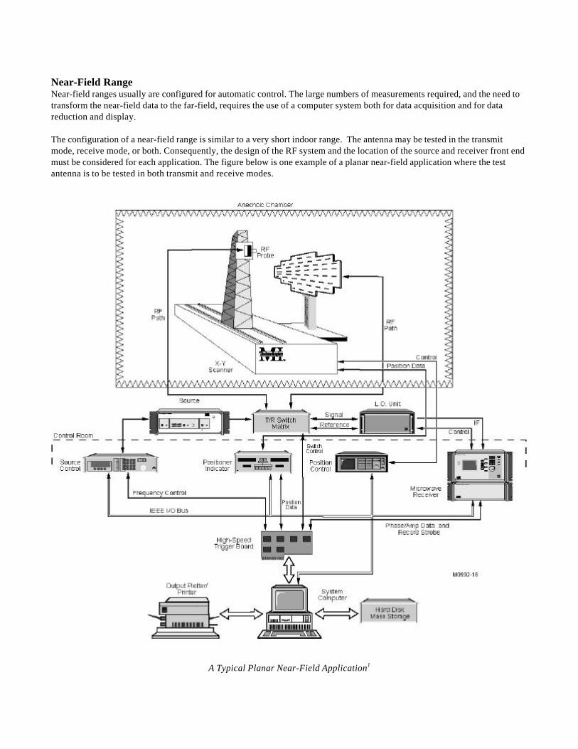
Near-Field RangeNear-field ranges usually are configured for automatic control. The large numbers of measurements required, and the need totransform the near-field data to the far-field, requires the use of a computer system both for data acquisition and for datareduction and display.
The configuration of a near-field range is similar to a very short indoor range. The antenna may be tested in the transmitmode, receive mode, or both. Consequently, the design of the RF system and the location of the source and receiver front endmust be considered for each application. The figure below is one example of a planar near-field application where the testantenna is to be tested in both transmit and receive modes.
A Typical Planar Near-Field Application1

ConclusionsAs technology progresses, the requirements placed upon wireless communication systems and their associated antennas willcontinue to become more stringent. For example, the desire to increase network capacity will result in the requirement toreduce adjacent channel interference within the system, which will result in more stringent antenna sidelobe and cross-polarization requirements.
The verification of the performance of antennas selected to meet these and other requirements will in turn require test rangeswith higher accuracy measurement capability. Fortunately the technologies used to advance the art of antenna design is alsobeing used to advance the design of antenna test and measurement ranges and instrumentation. Many of the simulation toolsavailable to antenna designers is also used to design antenna ranges. The increased use of commercial off-the-shelf hardwareand software, in conjunction with the increased use of automated test instrumentation networked into the local area network,will ensure that current state of the art antenna measurement systems will meet the needs of the advanced antennas andsystems coming to the wireless market place.
References:
[1] Product Catalog, Microwave Measurements Systems and Product, Microwave Instrumentation Technologies, LLC.
[2] R. Hartman and Jack Berlekamp, "Fundamentals of Antenna Test and Evaluation," Microwave Systems New andCommunications Tracking, June 1988.
[3] J.S. Hollis, T.J. Lyon, and L. Clayton, eds., Microwave Antenna Measurements, Scientific-Atlanta, Inc., 1985.
[4] R.C. Johnson and Doren Hess, "Conceptual Analysis of Measurements on Compact Ranges," Antenna ApplicationsSymposium, September 1979.
[5] R.C. Johnson editor, Antenna Engineering Handbook, McGraw-Hill Inc., 3rd edition, 1993.
Biography
Jeffrey A. Fordham received his BS and MS in electrical engineering from the Georgia Institute of Technology in 1989 and1990, respectively. He has 10 years experience in the design and evaluation of antennas and systems. Primary antenna designexperience has been in the design of space and millimeter wave aircraft antennas, and tracking and communication groundstation systems. He joined Microwave Instrumentation Technologies when the company was formed from the test andmeasurement instrumentation group of Scientific-Atlanta. Current responsibilities include the analysis and design of compact,and near-field antenna test ranges.