Embed Size (px)
Citation preview
Foreign Material Detection and Control
FSIS MeetingOmaha, NESept. 24, 2002

FDC Act
402(a)(3) “…consists in whole or in part of any filthy,
putrid, or decomposed substance or is otherwise unfit for food…”
402(a)(4) “…prepared packed or held under insanitary
conditions whereby it may have become contaminated with filth, or whereby it may have been rendered injurious to health…”
GMP 110.40(a)Equipment and Utencils
“...design construction, and use of equipment and utencils shall preclude the adulteration of food with lubricants, fuel, metal fragments, contaminated water, or any other contaminants…”
GMP 110.80(b)(8)Manufacturing Operations
“…Effective measures shall be taken to protect against the inclusion of metal or other extraneous materials in food. Compliance with this requirement may be accomplished by using sieves, traps, magnets, electronic metal detectors, or other suitable effective means…”

Controls Necessary
Required to control ‘adulteration’Specifically included in ‘HACCP’- physical hazards Prerequisite Programs CCP (?)
Allow judgement of system integrityPrevent customer complaints
Control Program
Incoming ingredients/raw materialsEquipment protectionAfter equipment which may fail or cause foreign materialsEnd of system (e.g. packing, load out points)

Ingredients/Raw Materials
Preventive approach
Supplier performance measure
GMP 110.80(a)(4), other regulations
Down time and associated costs
Equipment Protection
Protect expensive, sensitive equipmentExamples: cutters, grinders, extruders, pumps, etc.After equipment which may generate- cutter blades mechanical wear points
Maintenance/cleaning activityBreak system into measurable parts
End of Systems
Verification of overall program effectiveness
‘Proof’ of compliance- regulatory implications
Protection against customer issues
Detection/Control Devices
Magnets
Screens/Scalping/Sifting
Metal Detectors
X-Ray Devices

Magnets
Used to remove fine metals, not horseshoes
May require several passes to retain ‘paramagnetic’ materials
To protect equipment, particularly in explosive atmospheres
Magnet Function
Attraction proportionate to sizeStrength varies by inverse square of distance from surfaceField cannot be insulatedCan be demagnetized by abuse: extremes of heat, proximity of opposing fields, disassembly, etc.
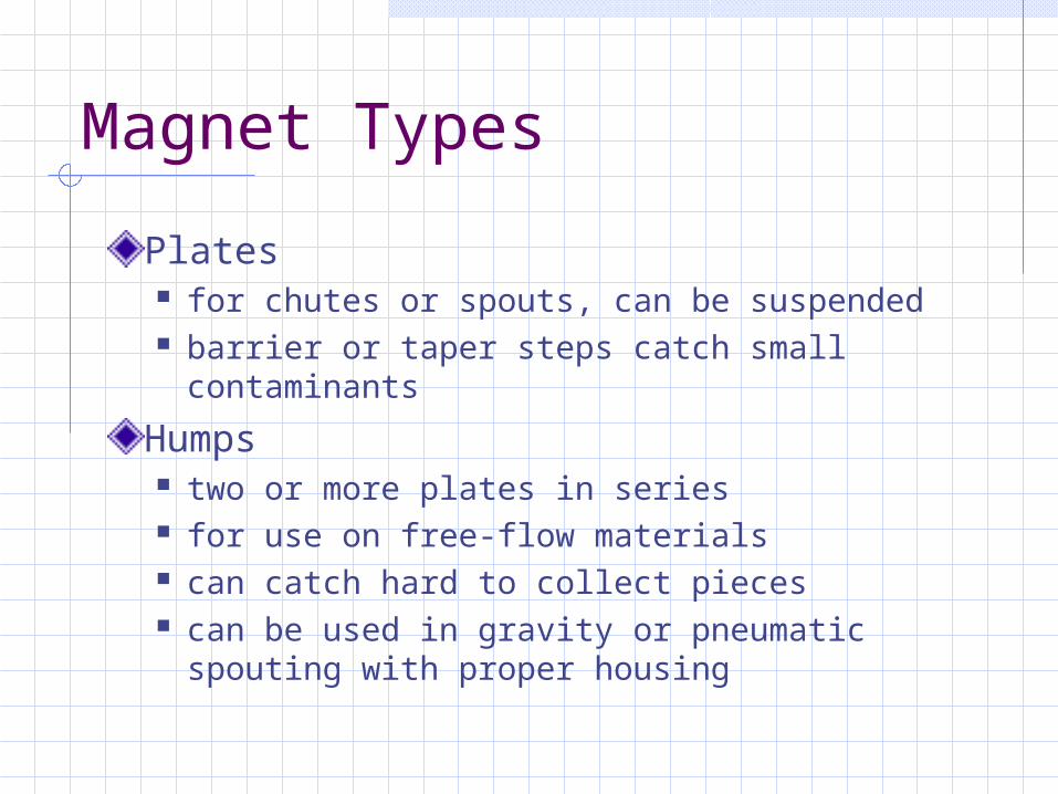
Magnet Types
Plates for chutes or spouts, can be suspended barrier or taper steps catch small
contaminants
Humps two or more plates in series for use on free-flow materials can catch hard to collect pieces can be used in gravity or pneumatic spouting
with proper housing

Magnet Types
Bar designed for fine contaminants in shallow
product streams product must be free-flowing
Grate for fine and small contaminants materials washed to underside of bar stream must be free flowing (no choke feed) metal must be in contact with bars

Magnet Types
Liquid traps group of round bars vertically installed in pipe
fitting contaminants washed to downstream side of
bars viscosity of material in stream affects results-
may need series of traps available in sanitary versions plate liquid trap also available with fitted baffle
to direct stream down onto magnet surface

Magnet Selection
Must consider types of expected contaminantsMust be sized to capacity of siteFlow characteristics must be consideredFabrication and construction are importantPrior planning required to select strength, assure access
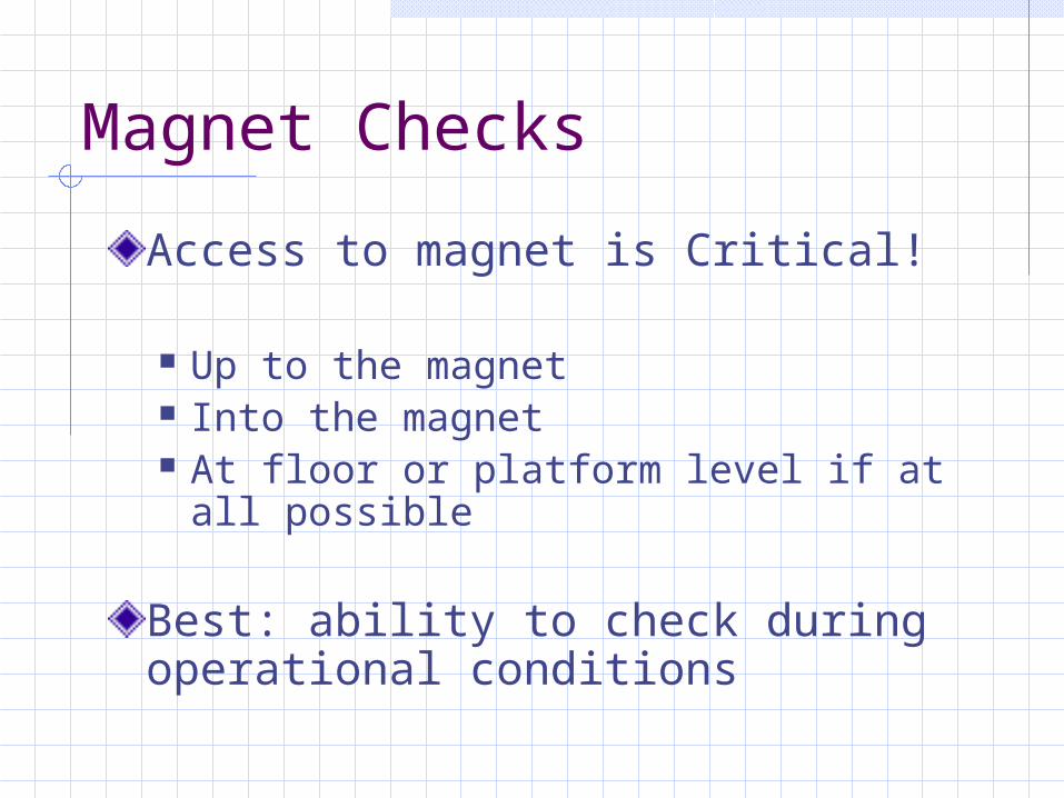
Magnet Checks
Access to magnet is Critical!
Up to the magnet Into the magnet At floor or platform level if at all
possible
Best: ability to check during operational conditions

Magnet Checks
Heavily contaminated magnets lose separation ability- pulling and holding power decreased
Expect complete cleaning and removal of any metallic materials supplier performance implications timing for decision making
Understand product flow, accumulations
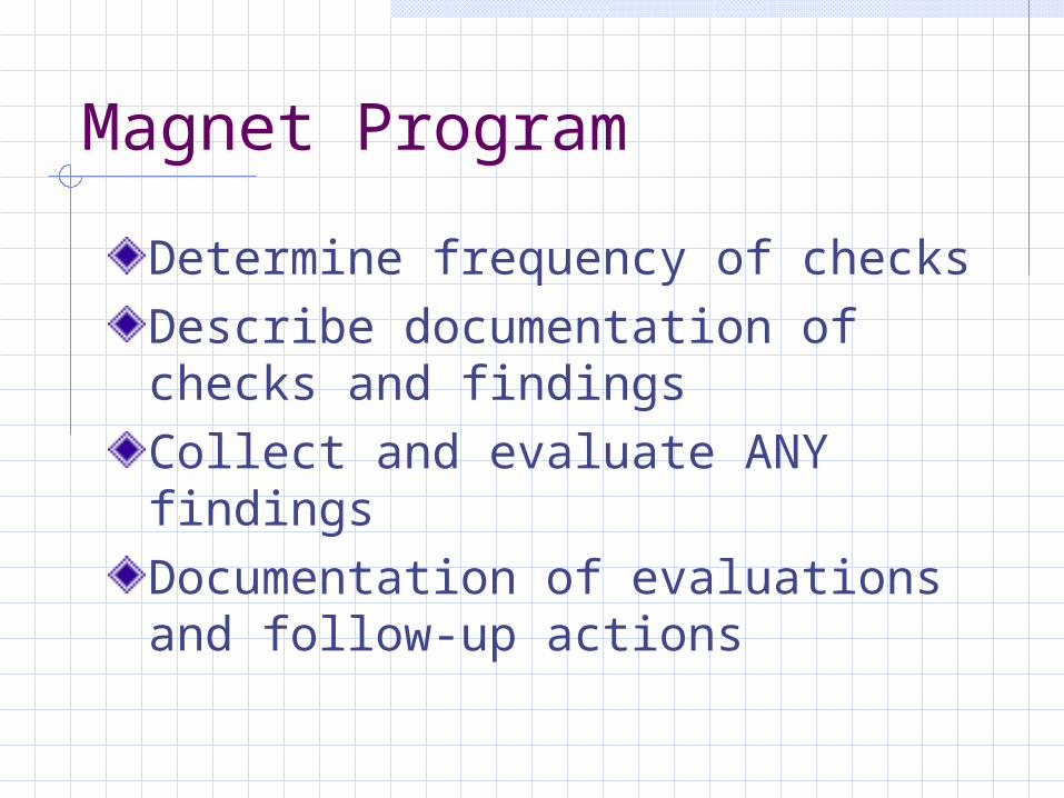
Magnet Program
Determine frequency of checksDescribe documentation of checks and findingsCollect and evaluate ANY findingsDocumentation of evaluations and follow-up actions
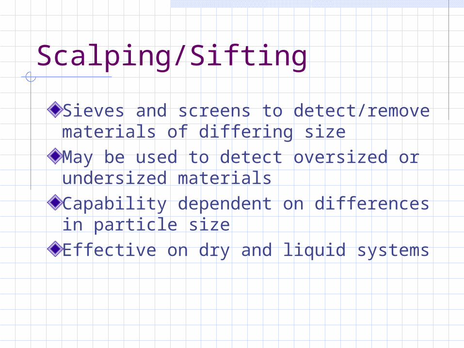
Scalping/Sifting
Sieves and screens to detect/remove materials of differing sizeMay be used to detect oversized or undersized materialsCapability dependent on differences in particle size Effective on dry and liquid systems

Screening/Scalping
Requires prior planningMust be matched to system purpose intended location in the system screen size and type
nylon wire plate
Screening/Scalping
Throughputs must be taken into account open area of screen available footprint
Particle sizes define separation capabilities bulk density is key

Screen/Scalp Types
Flow-through screens pump liquids through screen traps round hole, slots, wire sieve
Vibratory screen placed in product conveying
bed depth of bed and particle size affect
tailings quality
Screen/Scalp Types
Sweco circular vibration for reduced footprint vigorous screen movement can increase
separation rates may damage products
Box sifter gentle motion over screen surface usually for fine particles allows greater cloth surface
Screen/Scalp Types
Turbo sifters high speed rotary device within round
horizontal screen assembly rotary paddles throw material against
the screen surface may actually break-up foreign objects
Many not considered effective as product protection devices!
Scalper Tailings
Must maintain integrity of screen capture/tailings observations covers in place containers dedicated and identified
Must be able to collect tailingsSome screens/sifters may not ‘empty’Screens must be checked periodically for integrity

Scalper Tailings
Determine frequency of tailings and screen checksDocument findings for evaluationDocument maintenance of screens/sifting devicesDocumentation of evaluations and necessary action steps
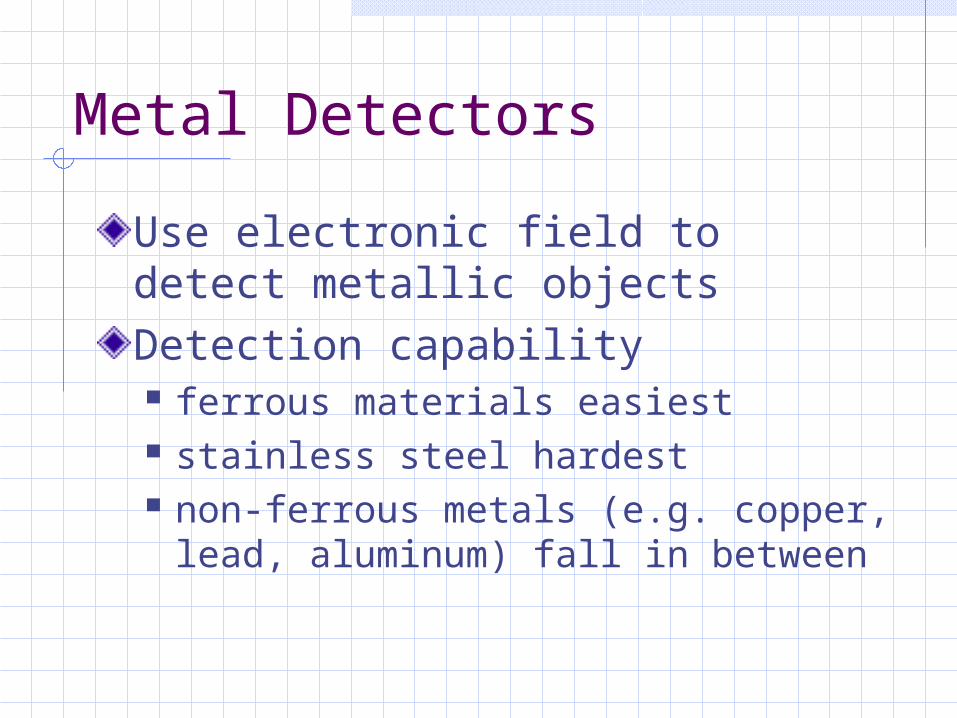
Metal Detectors
Use electronic field to detect metallic objectsDetection capability ferrous materials easiest stainless steel hardest non-ferrous metals (e.g. copper, lead,
aluminum) fall in between

Detector Principles
Balanced three coil system center coil transmitter two coils on either side act as receivers coils identical distance from transmitter
pick up the same strength of signal metallic particle moving through the
aperture changes signal strength change is amplified and processed
electronically to produce ‘detection’
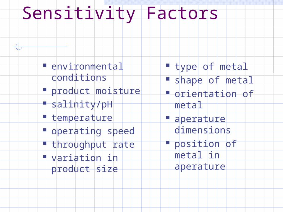
Sensitivity Factors
environmental conditions
product moisture salinity/pH temperature operating speed throughput rate variation in
product size
type of metal shape of metal orientation of
metal aperature
dimensions position of metal
in aperature
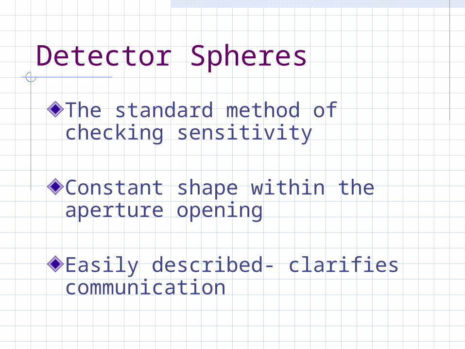
Detector Spheres
The standard method of checking sensitivity
Constant shape within the aperture opening
Easily described- clarifies communication
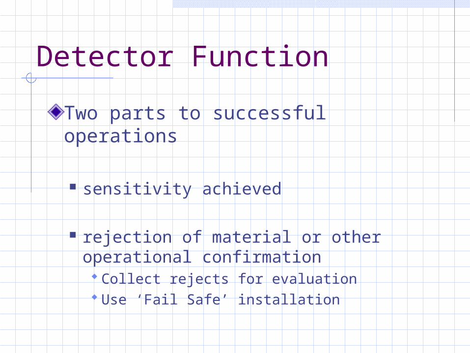
Detector Function
Two parts to successful operations
sensitivity achieved
rejection of material or other operational confirmation Collect rejects for evaluation Use ‘Fail Safe’ installation
Great, but...
Orientation effects on long contaminantsMay not be 100% effectiveDrift on sensitivity or reject device can change capability Operators may not know ‘standards’ or check proceduresProduct effect may limit sensitivity

Ball Size and Wire Size
Each Item Drawn to Scale
S teelP aper C lip
D ia 0.95mm(0.037")
S pheric alS ensitivity(Fe B all)
T inned C opperW ire
D ia 0.91mm(0.036")
C opperW ire
D ia 1.37mm(0.054")
S tainlessS teel E N 58ED ia 1.60mm
(0.063")
1.2 mm
1.5 mm
2.0 mm
2.5 mm
1.5 mm long(0.06")
3.0 mm long(0.12")
6.0 mm long(0.24")
11.0 mm long(0.44")
3.5 mm long(0.14")
9.0 mm long(0.36")
26.0 mm long(1.02")
55.0 mm long(2.17")
3.0 mm long(0.12")
8.0 mm long(0.31")
24.0 mm long(0.96")
64.0 mm long(2.52")
8.0 mm long(0.31")
18.0 mm long(0.72")

Product Effects
Dry products allow higher frequency operation- better stainless detectionWet products require lower frequency operation- geared to ferrous detectionMoisture/salinity and shape may show large product effect
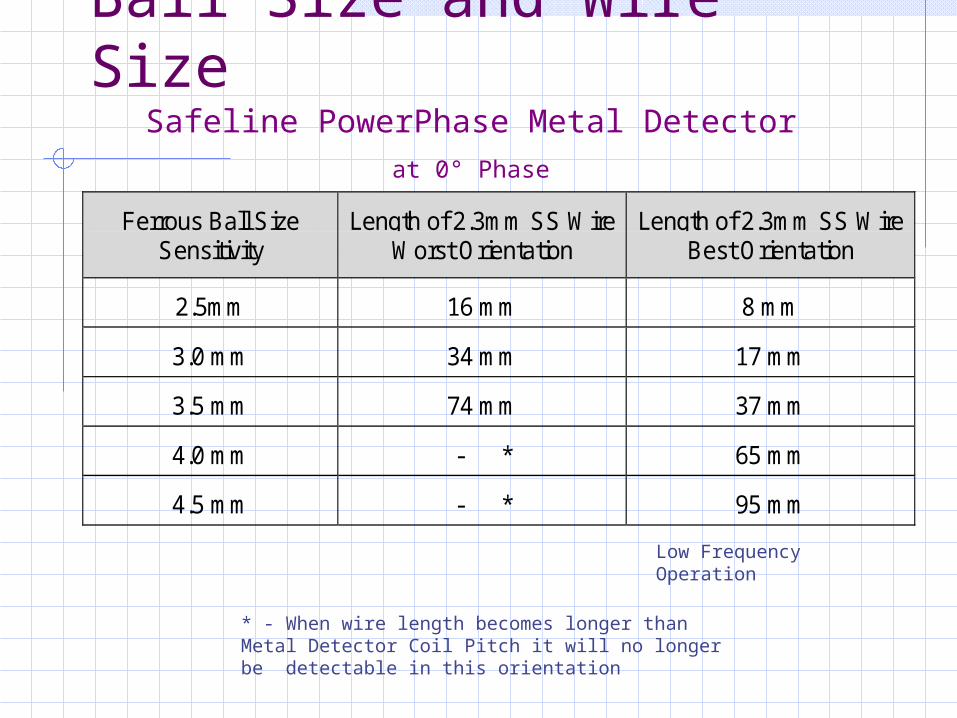
Ball Size and Wire Size
Ferrous Ball SizeSensitivity
Length of 2.3mm SS WireWorst Orientation
Length of 2.3mm SS WireBest Orientation
2.5mm 16 mm 8 mm
3.0 mm 34 mm 17 mm
3.5 mm 74 mm 37 mm
4.0 mm - * 65 mm
4.5 mm - * 95 mm
* - When wire length becomes longer than Metal Detector Coil Pitch it will no longer be detectable in this orientation
Safeline PowerPhase Metal Detector
at 0° Phase
Low Frequency Operation
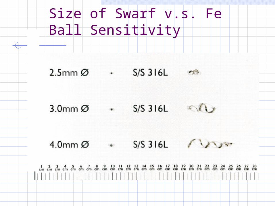
Size of Swarf v.s. Fe Ball Sensitivity
Detection Program
Confirm operation of checks
Confirm documentation of checks and findings
Documentation of actions taken and investigation results
X-Ray Devices
Operates on differential absorption
Absorption related to product density and thickness
Density of ‘targets’ and substrate affect detection/identification
X-Ray Devices
Principle of operation x-ray fan beam projected onto diode array scintillator converts to visible photons photodiodes register pass-through energy absorption of energy measured to create
‘picture’ electronically compared to ‘standard’ ‘reject’ or signal triggered
X-Ray Devices
Units available for linear transfer or enclosed liquid systems
Has capability to detect some sizes of contaminants (i.e. metals, glass, maybe bone, etc.)
Software program to interpret image is critical component
Capability
Sensitivity determined by number of photodiodes in arrayResolution affected by product speed through detectorAbsorption affected by density differential between ‘contaminant’ and substrateSoftware enables differentiation

Capability Advantages
Sees through aluminum materials
No freeze/thaw effects
Salty/wet/variable fat content- no effect

Selection Considerations
Requires larger foot-printNot for drop-thru applicationMust know application- expected contaminants (density)Line speeds operate lower than metal detectors (up to 400fpm vs. 700fpm)Contaminant shape and orientation affects capability
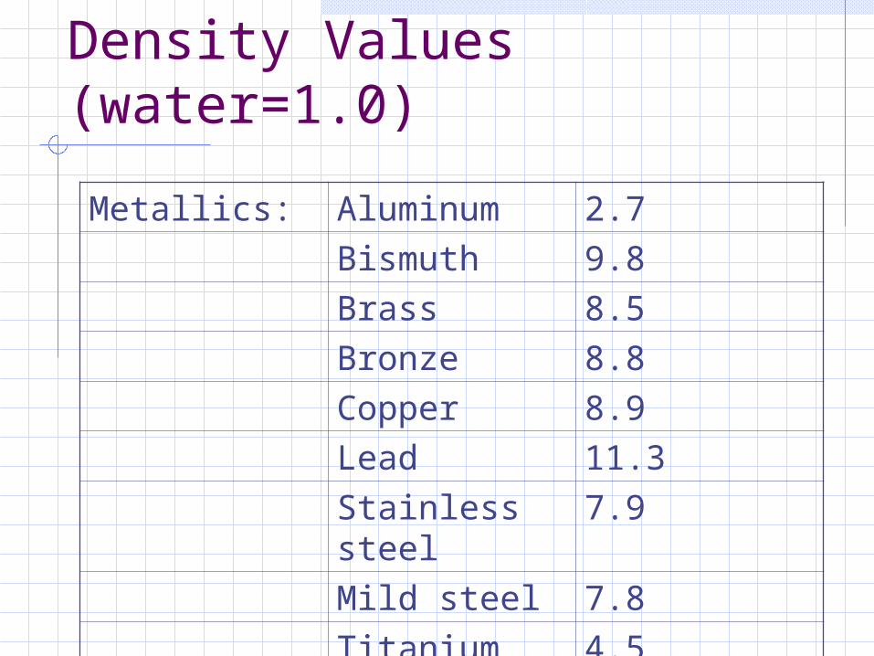
Density Values (water=1.0)
Metallics: Aluminum 2.7
Bismuth 9.8
Brass 8.5
Bronze 8.8
Copper 8.9
Lead 11.3
Stainless steel
7.9
Mild steel 7.8
Titanium 4.5

Density Values (water=1.0)
Non-metallic: Bone 1.8
Concrete 2.4
Epoxy resin 1.1
Crown glass 2.6
Flint glass 4.2
Nylon 1.15
Polyethylene 0.94
Polypropylene
0.90
Rubber 0.9

Orientation Effect
Location of object within product On top easier to find Buried within product more difficult
Objects smaller than test sphere If on edge- needs to be as deep Flat pieces need to have necessary
depth
Software Enables Capability
Dependent on each application situation
Manipulation of grayscale values allows multiple factor evaluation
Software allows analysis by programmed shapes- round, long, etc.
Foreign Material Control
Sources within facilities are many and varied- e.g. ingredients, systems, peopleRequired to assure compliancePREVENTION of issues is keyMany factors determine selectionActive documented monitoring and evaluation procedures are required
Conclusion
Detection equipment is requiredPrior planning makes it work betterAll parts of the program must work- include employee trainingProper operation and documentation must be expectedFindings require evaluations, follow-upRecords are important