Embed Size (px)
Citation preview

RTO-EN-AVT-207 2 - 1
Foreign Object Damage and Fan Blade Out
H. CHALONS, A. SUFFIS France
1.0 INTRODUCTION Bird strikes in a turbofan engine as well as fan blade-outs can result in serious damage to the engine. For each new engine model, design requirements prescribe to demonstrate the ability to withstand those phenomena using appropriate test on full engine. In order to design the engine and notably to increase the engine efficiency, the engine manufacturers usually validate their design before the full engine test on partial tests using only few blades. As a supplement to those tests, they also do analyses with non-linear transient structural code to predict and optimise the design and improve the behaviour of the engine in such cases.
Therefore, all the components – i.e. parts of the engine and the bird – have to be modelled with the adequate accuracy in order to predict properly the behaviour of the engine with a good correlation with experiments. That requires both:
• Accurate modelling of the material behaviour including non-linear effect including plasticity or damage,
• Adapted numerical methods to make possible the modelling of specific behaviours such as the bursting out of the bird after the impact.
This paper aims at describing the key points of the simulation and of the modelling in the event of fan blade-out and bird impact. Successively for the both cases:
• The design requirements are quickly reminded in order to define clearly the stakes of the tests, as well as those of the simulations. It allows us also to list, from the beginning, the main challenges which must be undertaken by the simulation.
• Then, the different steps of the simulation are described. Blade-outs and bird strikes are indeed dynamic phenomena and involve rotating parts. Some precautions have to be taken to be able to compare numerical results with the reality.
• The main characteristics of each analysis are discussed afterwards. These discussions involve the way the different parts are modelled in terms of numerical elements and material models used. Two key points are particularly addressed in this section. The first one is the original way used to describe the behaviour of the bird: as the classical finite element is not able to treat completely the bird fragmentation after the impact, one uses SPH (Smooth Particle Hydrodynamics) method. The second one concerns a specific model used to represent the damage and the rupture. As such model usually suffers from pathological mesh dependence, it is generally coupled to a proper numerical method in order to avoid it. In our case, a delay damage model is then included in the classical definition of the evolution of the damage.
• Some examples of results are eventually described.
To start with, some basis are given in the range of fast transient dynamic simulation.
Finally, the reader has to bear in mind that this document mainly deals with to the metallic blades. If the methodologies, meshes, fundamental basis etc. are on the whole shared between metallic blades and other technologies, this document deals only with the specific key points of the metallic modelling.
Foreign Object Damage and Fan Blade Out
2 - 2 RTO-EN-AVT-207
2.0 FAST TRANSIENT DYNAMICS BASIS
2.1 Algorithm All the phenomena discussed hereafter have the common characteristic of being very short time phenomena (about a few milli-seconds long). The main events only last half a round for an ingestion and is rarely longer than one or two rotation for a blade-out (that is if one is only interested in the blades and the casing). The phenomena to model are then eminently dynamic. In such case, during all the duration of the event, one has to solve the following equation for all point of the mesh of the structure:
[ ] [ ] )()()( tFtUKtUM ext=+&&
where [M] is the mass matrix of the structure, )(tU , )(tU&& the displacement and acceleration of the nodes of the mesh, functions of time, [K] the updated stiffness matrix and Fext(t) the external forces applied on the nodes.
In addition to the classical spatial discretization corresponding to finite element, one has to use a proper numerical integration scheme in order to solve the equation in time. In dynamic cases, such as the one studied here, it is more convenient to use explicit schemes as the Newmark ones [1]. It mainly consists in a Taylor series development [2] of the displacement and velocity leading to the following expressions of the discretized displacement tU and velocities tU& at time t, under certain conditions of the approximation of the residual integral:
( )⎪⎪⎩
⎪⎪⎨
⎧
+Δ
+=
Δ+Δ+=
Δ+Δ+
Δ+
tttttt
ttttt
UUtUU
UtUtUU
&&&&&&
&&&
2
22
2
where tΔ is the step time of the schemes. This specific form is known as the central difference method. Knowing the values of all variables at time t, it is then possible to calculate the displacement at the next time step without any iteration, i.e. explicitly. Knowing the actual rigidity of the material, it is then possible to solve the equilibrium equation and determine the acceleration at the next step, then the velocity and the displacement at the next step and so on.
If this scheme presents many advantages, it has a major inconvenient. It is conditionally stable [3]. In other terms, a specific condition on the step time has to be respected in order not to diverge. This condition is given hereafter and expresses the fact that the step time must not be bigger than the time needed for the wave to cross (at the celerity ρEc = ) the smallest element of the structure (characterized by its smallest length lmin).
cltt crit
min=Δ≤Δ
That means in particular that one has to be very careful when the mesh is realised; a single very small element will impose indeed a very small time step to the whole structure, increasing by the same factor the CPU time. That is why dynamic analysis often require specific meshing of the structure.
Foreign Object Damage and Fan Blade Out
RTO-EN-AVT-207 2 - 3
2.2 Contact
During the phenomena discussed here, contacts between different parts occur. The surfaces in contact slide one on an another and the contact zone evolves in respect to the time. Therefore, the treatment of sliding and impact is very important. The method generally used is a penalty method. It consists in applying a normal interface force to all penetrating nodes to the contact surface. The intensity of the force depends on the stiffness of the two parts and the distance of penetration and must be sufficient to guarantee the non-penetration of the two contact surfaces. This method is widely used in many commercial explicit (as implicit) codes.
2.3 Element
Nowadays, solid elements are generally used to mesh the structure in the case we discussed. However, it is also possible to find some shells and thick shells in some cases. The more common element is the brick element but today practises tend to use more and more under-integrated element (i.e. with a single integration point). If it has the main advantage to reduce the CPU time, it requires specific models to control the zero energy modes, called hourglassing modes, which can lead to a divergence of the calculation. The hourglass models are generally based on the adding of a viscous damping resisting to the undesirable hourglassing modes without affecting on the dynamic response.
Specific elements are used to model the bird. They are described in the appropriate following section.
3.0 DESIGN REQUIREMENTS
3.1 Bird Strike The design requirements (Federal Aviation Regulations for the US and Joint Aviation Requirements for Europe) related to bird strike are defined to guarantee the ability of the engine to behave properly after such an event. Depending on the size of the bird ingested, the rules differ:
• For medium birds (from 1.5lbs to 2.5lbs), the engine must continue to be functional with a maximum loss of thrust of 25% in order to allow an Air-Turn-Back and a landing. That means in particular that rupture of fragment of blades is tolerated as long as the criteria are respected.
• In the rare eventuality of a large bird (over 4lbs), the ability to stop the engine without major incident (ejection of a debris, uncontrolled fire) must be demonstrated. The size of the bird depends in that case on the diameter of the engine; the larger the engine, the heavier the bird. The cases where the blades break must be covered by the fan blade-out study.
Tests are always performed to guarantee the good behaviour of the engine in such a case. Simulations are useful to determine properly the most critical case and to demonstrate equivalence between cases (for instance, large bird less critical than blade-out). In the case of medium birds, residual thrust is evaluated after the ingestion by mounting the bulged blades on a full engine.
3.2 Blade-Out As for the bird strike, design requirements related to blade-out are defined to guarantee the ability of the engine to behave properly after such an event. In order to guarantee the integrity of the plane, three main points must be verified:
• The retention of all debris inside the casing to avoid dramatic consequences for the safety of the whole plane,
Foreign Object Damage and Fan Blade Out
2 - 4 RTO-EN-AVT-207
• The non-loss of all blades following the one which is lost in order to avoid an uncontrolled unbalance and a divergence of the phenomenon,
• The integrity of the axial retention system of the following blade.
As for the bird strike, tests are always performed for the fan blade-out.
4.0 BIRD STRIKE
4.1 Introduction
This section describes the different aspects of bird impacts. To start with, the meshes used are described for the blades and the bird. A particular emphasis is put on the SPH elements used for bird modelling. Secondly, the main aspects of material modelling are described. Finally, the different steps of a bird impact simulation are presented and some results are briefly commented.
4.2 Meshes
Blades and Rotating Parts
A bird strike simulation requires the meshing of several blades. Only the blades, which contribute to cut the bird, are modelled. For the most common cases, the mesh of the blades can be cut at their root. In that particular case, shell elements, thick shell elements or brick elements can be used. The choice between one and the other will depend on the targeted precision. For first iterations of quick simulations, shell elements are recommended as they can be changed easily. For more precise simulations, brick elements with a coarse adapted mesh including several elements in the thickness of the blade are recommended. However, for larger birds or when bird impact is located near the root of the blade, one can decide to include the full blade modelling, the disk, the platform and the other parts which contribute to axial blocking of the blade to avoid too much constrained hypothesis on the boundary conditions. Use of volume elements is then mandatory. One has to bear in mind that the coarser the mesh is, the smaller the time step. It is therefore very important to control precisely the refinement of the mesh and the local distortion or particularities, as it can have significant negative consequence impact on the CPU time.
Bird
A specific method, called Smooth Particle Hydrodynamics (SPH) method, has been especially developed to model the bird, its deformation and its possible slicing by blade or other parts. This formulation has been implemented in the past in the fast transient dynamic analysis code Europlexus developed at the French ‘Commissariat à l’Energie Atomique’ (CEA) [8,9] and is now available in many commercial codes as LS-Dyna [10]. The SPH method has been initially developed by astrophysicists to simulate non-axisymmetrical phenomena during the 70’s. But, at the beginning of the 90’s, some mechanical scientists have adapted this method to treat impacts at very high velocity. In fact, the SPH formulation calculates with accuracy problems that present high deformations and high displacements, and is also well adapted for modelling birds.
In that kind of modelling, bird is meshed using a cloud of elements (see figure 2-1), each of them containing only one node. Each element represents indeed a part of the full mass of the bird and the node corresponds to the barycentre. When visualized, the elements (or the particle) are generally represented with spheres, but no geometric specifications are in fact associated. This method is a Lagrangian one, which implies that only the bird is meshed (opposite to eulerian method). Using this method, the deformation of the bird and its burst are immediate which is the main advantage. Conversely, the main

Foreign Object Damage and Fan Blade Out
RTO-EN-AVT-207 2 - 5
shortcoming is that connectivity of elements has to be recalculated when the connectivity for a classical mesh does not change.
2h2h
Figure 2-1: Example of simple bird mesh on the right. On the left, the particle in grey with dark circle are the one which interact with the central black one.
That kind of element, and particularly the fact the connectivity evolves with time, implies necessarily specific method. The SPH mathematical basis consists in the regularization of a discrete field f by a field family <f>h, which has the good properties of continuity and derivation:
∫Ω
−=>< dyhyxWyfxf h ),().()(
The parameter h determines the volume around the point x where the Kernel W takes its greatest values (see figure 2-1). Different kinds of smoothing Kernel are used; for instance, Europlexus used a cubic Kernel with compact support:
⎪⎪⎪⎪
⎩
⎪⎪⎪⎪
⎨
⎧
≥
≤≤⎟⎠⎞
⎜⎝⎛ −
≤≤⎟⎟⎠
⎞⎜⎜⎝
⎛⎟⎠⎞
⎜⎝⎛+⎟
⎠⎞
⎜⎝⎛−
=
20
21241
1021
32
23
1),(3
32
3
hr
hr
hr
hr
hr
hr
hhrW
π
This integral can be approximated by a discrete sum on a finite number of points {xi} in the domain Ω.
∑ −=><i
ii
iih hxxW
xxfmxf ),(.
)()()(
ρ
where mi is the mass of the particle xi and ρ the density of the material that fills the domain Ω.. Using a similar methodology, it is possible to evaluate the gradient and the partial derivative of a function. With an adapted neighbours searching method imposed by the very nature of the SPH method [10], it makes possible the resolution of conservative equations for SPH elements.
Some other aspects of the SPH methodology are not described in this document as:
• Specific contact algorithms [8, 9] has been also developed in order to be able to couple SPH elements and standard finite elements,
• Specific methodology to be able to model properly the slicing and the burst of a SPH part [9].
Foreign Object Damage and Fan Blade Out
2 - 6 RTO-EN-AVT-207
4.3 Material Modelling
Blades
Considering the event we want to model and the material used for the blade (mainly titanium as other technologies of blades are not considered in that paper), many material behaviours must be modelled:
• The plasticity of the blades impacted directly by the bird. As the load are highly dynamic and as some materials such as titanium are highly dependent on the strain rate to which they are subjected, rate dependence must be taken into account. The modelling of this phenomenon is all the more important as the strain rate encountered in such cases can reach several thousands of s-1, leading to an increase of the yield stress of several dozens percents for the titanium comparing to the quasi-static behaviour. The two models described hereafter to illustrate this behaviour are the Johnson-Cook model and the Steinberg-Lund-Zerilli-Armstrong model (named SLZA hereafter).
• The damage and occasionally the rupture of material. Those aspects will not be treated in this part as they are usually not taken into account, oppositely to the case of blade-out treated hereafter.
Johnson-Cook model [6] is purely empirical and allows to model properly the plasticity of material and it also takes into account the effect of strain rate. In the form usually used as given in the equation below, five parameters (C1, C2, C3, n and m) must be identified by appropriate dynamic and static tests as Hopkinson bar test.
( )( )( )mp
np TCCC −++= 1ln1 *
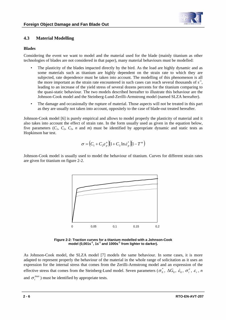
321 εεσ & Johnson-Cook model is usually used to model the behaviour of titanium. Curves for different strain rates are given for titanium on figure 2-2.
0 0,05 0,1 0,15 0,2
Figure 2-2: Traction curves for a titanium modelled with a Johnson-Cook model (0,001s-1, 1s-1 and 1000s-1 from lighter to darker).
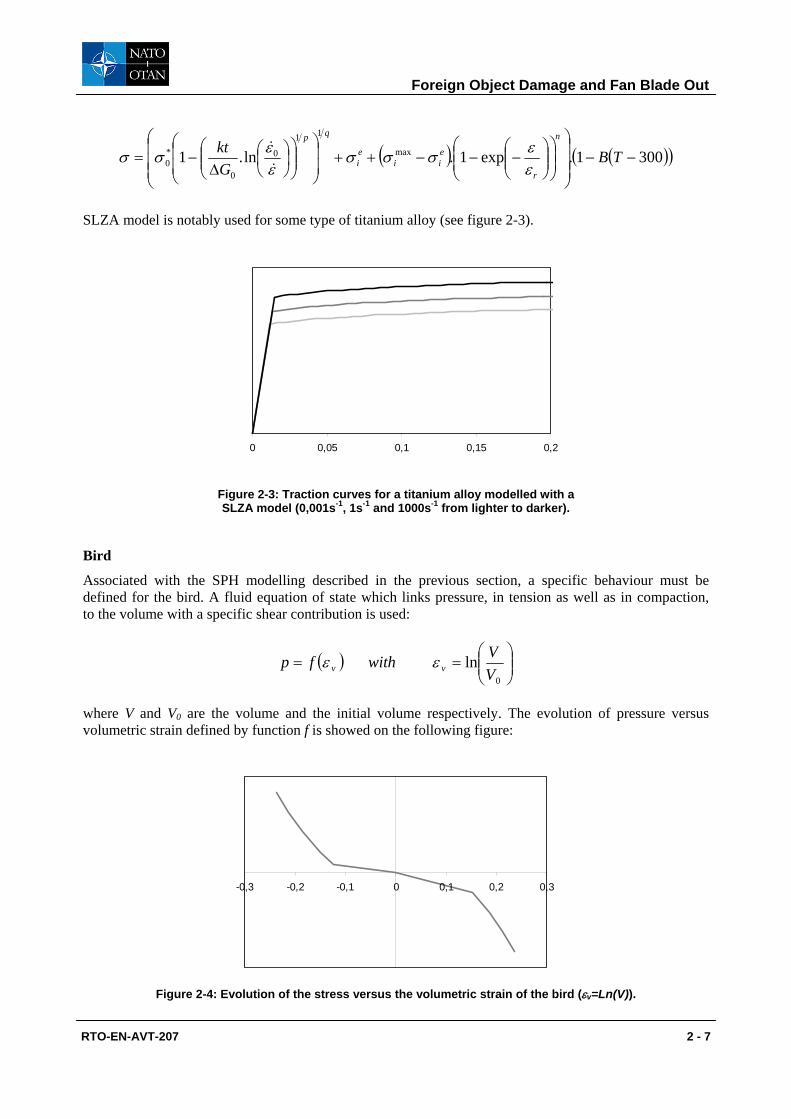
As Johnson-Cook model, the SLZA model [7] models the same behaviour. In some cases, it is more adapted to represent properly the behaviour of the material in the whole range of solicitation as it uses an expression for the internal stress that comes from the Zerilli-Armstrong model and an expression of the effective stress that comes from the Steinberg-Lund model. Seven parameters ( *
0σ , 0GΔ , 0ε& , eiσ , rε , n
and maxiσ ) must be identified by appropriate tests.
Foreign Object Damage and Fan Blade Out
RTO-EN-AVT-207 2 - 7
( ) ( )( )3001.exp1.ln.1 max
11
0
0
*0 −−
⎟⎟⎟
⎠
⎞
⎜⎜⎜
⎝
⎛
⎟⎟⎠
⎞⎜⎜⎝
⎛⎟⎟⎠
⎞⎜⎜⎝
⎛−−−++
⎟⎟
⎠
⎞
⎜⎜
⎝
⎛⎟⎟⎠
⎞⎜⎜⎝
⎛⎟⎠⎞
⎜⎝⎛
Δ−= TB
Gkt
n
r
eii
ei
qp
εεσσσ
εεσσ&
&
SLZA model is notably used for some type of titanium alloy (see figure 2-3).
0 0,05 0,1 0,15 0,2
Figure 2-3: Traction curves for a titanium alloy modelled with a SLZA model (0,001s-1, 1s-1 and 1000s-1 from lighter to darker).
Bird
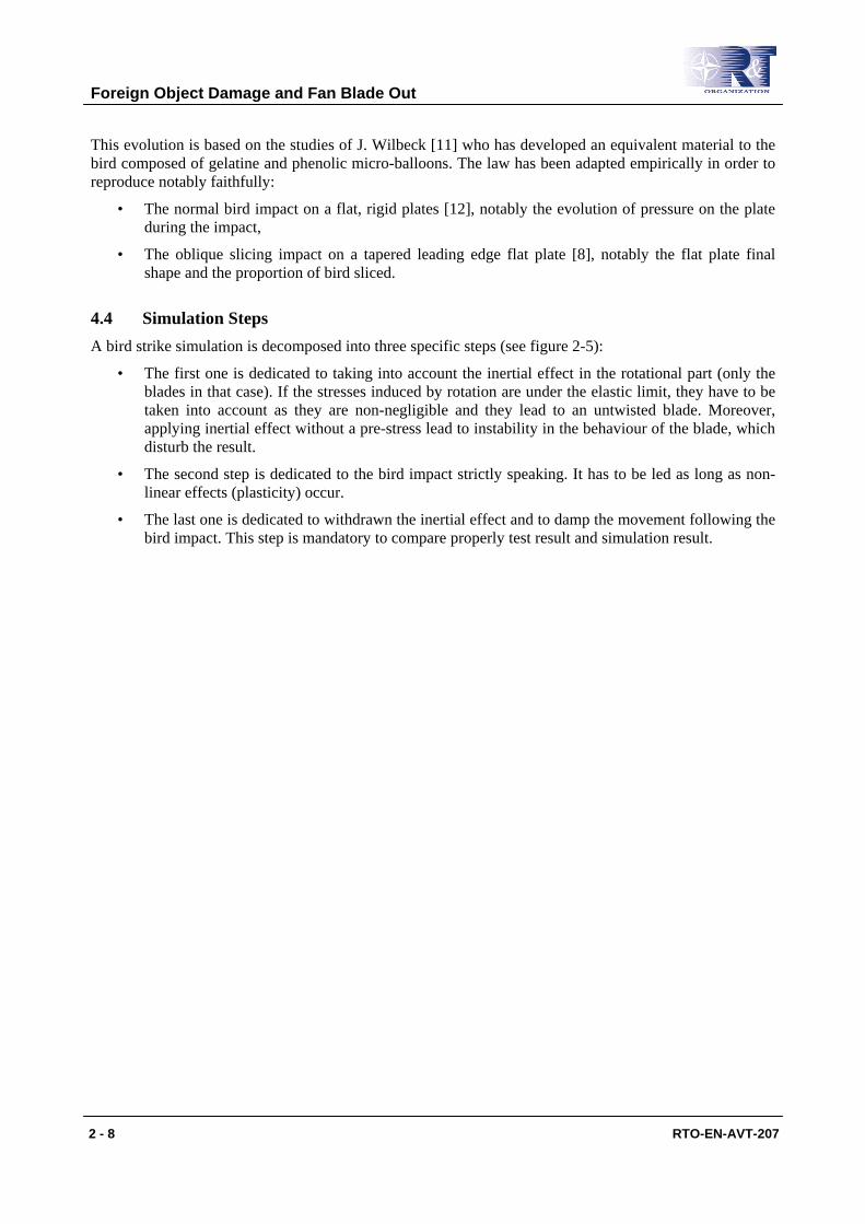
Associated with the SPH modelling described in the previous section, a specific behaviour must be defined for the bird. A fluid equation of state which links pressure, in tension as well as in compaction, to the volume with a specific shear contribution is used:
( ) ⎟⎟⎠
⎞⎜⎜⎝
⎛==
0
lnVVwithfp vv εε
where V and V0 are the volume and the initial volume respectively. The evolution of pressure versus volumetric strain defined by function f is showed on the following figure:
-0,3 -0,2 -0,1 0 0,1 0,2 0,3
Figure 2-4: Evolution of the stress versus the volumetric strain of the bird (εv=Ln(V)).
Foreign Object Damage and Fan Blade Out
2 - 8 RTO-EN-AVT-207
This evolution is based on the studies of J. Wilbeck [11] who has developed an equivalent material to the bird composed of gelatine and phenolic micro-balloons. The law has been adapted empirically in order to reproduce notably faithfully:
• The normal bird impact on a flat, rigid plates [12], notably the evolution of pressure on the plate during the impact,
• The oblique slicing impact on a tapered leading edge flat plate [8], notably the flat plate final shape and the proportion of bird sliced.
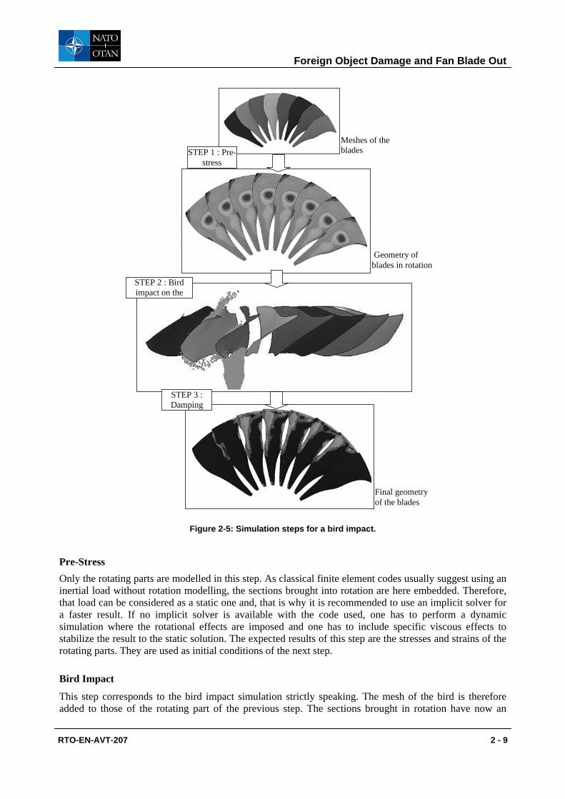
4.4 Simulation Steps A bird strike simulation is decomposed into three specific steps (see figure 2-5):
• The first one is dedicated to taking into account the inertial effect in the rotational part (only the blades in that case). If the stresses induced by rotation are under the elastic limit, they have to be taken into account as they are non-negligible and they lead to an untwisted blade. Moreover, applying inertial effect without a pre-stress lead to instability in the behaviour of the blade, which disturb the result.
• The second step is dedicated to the bird impact strictly speaking. It has to be led as long as non-linear effects (plasticity) occur.
• The last one is dedicated to withdrawn the inertial effect and to damp the movement following the bird impact. This step is mandatory to compare properly test result and simulation result.
Foreign Object Damage and Fan Blade Out
RTO-EN-AVT-207 2 - 9
Meshes of the blades
Final geometry of the blades
Geometry of blades in rotation
STEP 1 : Pre-stress
STEP 2 : Bird impact on the
STEP 3 : Damping
Figure 2-5: Simulation steps for a bird impact.
Pre-Stress Only the rotating parts are modelled in this step. As classical finite element codes usually suggest using an inertial load without rotation modelling, the sections brought into rotation are here embedded. Therefore, that load can be considered as a static one and, that is why it is recommended to use an implicit solver for a faster result. If no implicit solver is available with the code used, one has to perform a dynamic simulation where the rotational effects are imposed and one has to include specific viscous effects to stabilize the result to the static solution. The expected results of this step are the stresses and strains of the rotating parts. They are used as initial conditions of the next step.
Bird Impact
This step corresponds to the bird impact simulation strictly speaking. The mesh of the bird is therefore added to those of the rotating part of the previous step. The sections brought in rotation have now an
Foreign Object Damage and Fan Blade Out
2 - 10 RTO-EN-AVT-207
imposed motion equal to the maximum rotation speed of the engine and an initial velocity which corresponds to the maximum velocity of the plane during take-off, is applied to the bird. A contact is defined between the bird and the impacted blades and, if needed, between all parts of the engine modelled in contact. The impact height and ortho-radial positioning of the bird must correspond to the one of the test one want to study, but the ortho-radial positioning is less important than the impact height as the critical blades are not the first ones, but the ones which slices the most massive part of bird which are located in the middle of the bird.
Depending on the size of the bird, the simulation is then performed for few milli-second, which are usually sufficient to take into account all non-linear effects. The bird is then sliced successively by the blades. As the blade rotation is higher than the velocity of the bird, the slice spreads out on the pressure side of the blades and applies important loading on them, leading to:
• Plastic deformations of the leading edge forming progressively a characteristic bulge,
• Damage and rupture of all or part of the impacted blades (this point will be addressed in the section on the blade-out),
• Flexion of the blade, which can possibly make necessary the study (and so the modelling) of the behaviour of the disk and of the axial retention system. This flexion is, in most cases, not sufficient to lead to a contact between two successive blades.
The bird is then centrifuged and thrown backward. Contacts between the remains of the bird and other parts (casing, OGV, etc.) are usually not studied as they do not lead to critical loading on these parts.
If the main results are obtained with the final step described hereafter, this simulation allows one to:
• Verify that the ingestion is modelled properly (behaviours of the bird and of the blades, etc.),
• Estimate the masses of bird impacting each blades,
• Determine the maximum deflection of the impacted blades and, if strain gauges are used, to compare the gauge signals and the simulation results,
• Study the plasticity of the impacted blades and notably verify, using a simple equivalent plastic strain criteria, that no rupture will occur in any part of the impacted blades.
Damping Simulation
As for the pre-stress, only the rotating parts are modelled considering their sections brought in rotation are embedded, but, at the opposite, the inertial effects are here withdrawn. The initial conditions in strain and stress correspond to the last state of the previous step. As the goal of this step is to obtain the final geometry, including plasticity, without any other loading, one must damp the different vibrations at the end of the impact. Therefore, no loading is applied in this step and only an adequate damping is used.
An implicit solver as well as an explicit one can be used for this step, but the implicit one is more efficient.
The main result of this simulation and the most important of the whole process is the final geometry of the impacted blades. It allows one to:
• Compare them to the experimental one,
• Determine the different measures of the bulge on the deformed blade in order to evaluate the impact on the thrust.

Foreign Object Damage and Fan Blade Out
RTO-EN-AVT-207 2 - 11
4.5 Bird Strike Simulations Some examples of bird strikes on metallic blades and of specific post-treatments are given in this section to illustrate the characteristic results usually obtained. They have been obtained with LS-Dyna simulations. Depending on the simulation considered, the blades have been cut at their roots or the disk and axial retention system are modelled.
Various results are given on the following figures:
• The third image of figure 2-5 gives a visualisation of the slicing of the bird,
• The fourth image of figure 2-5 gives a visualisation of the final shape and the level of plasticity of impacted blades,
• Figure 2-6 presents a zoom on the bulge of an impacted blade and figure 2-7 shows an example of the different measures realised on the bulge,
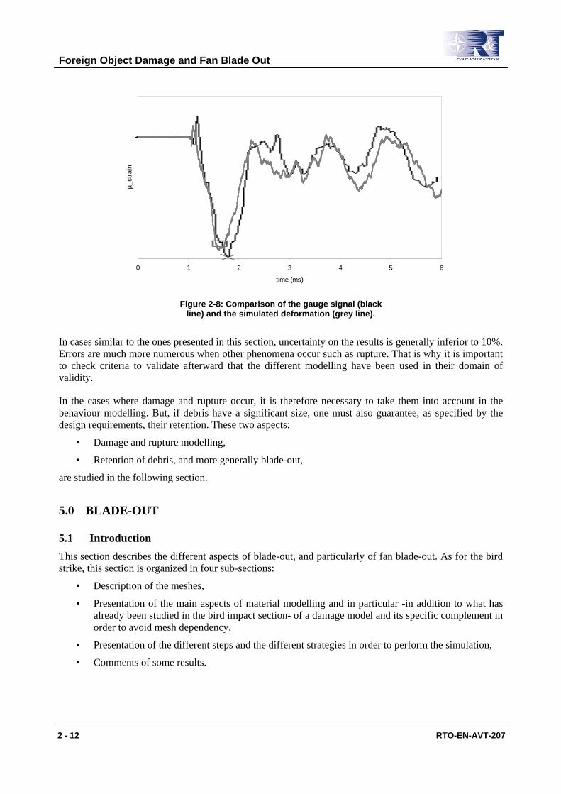
• Figure 2-8 gives a comparison of a signal measured on a gauge located at the middle of the pressure side and of the simulated deformation.
Figure 2-6: Plasticity levels on the bulge of an impacted blade.
top
lenght
root deflection height
root
top LE
TE
top deflection
Figure 2-7: Measures realised on the bulge.
Foreign Object Damage and Fan Blade Out
2 - 12 RTO-EN-AVT-207
0 1 2 3 4 5 6
time (ms)
µ_st
rain
Figure 2-8: Comparison of the gauge signal (black line) and the simulated deformation (grey line).
In cases similar to the ones presented in this section, uncertainty on the results is generally inferior to 10%. Errors are much more numerous when other phenomena occur such as rupture. That is why it is important to check criteria to validate afterward that the different modelling have been used in their domain of validity.
In the cases where damage and rupture occur, it is therefore necessary to take them into account in the behaviour modelling. But, if debris have a significant size, one must also guarantee, as specified by the design requirements, their retention. These two aspects:
• Damage and rupture modelling,
• Retention of debris, and more generally blade-out,
are studied in the following section.
5.0 BLADE-OUT
5.1 Introduction This section describes the different aspects of blade-out, and particularly of fan blade-out. As for the bird strike, this section is organized in four sub-sections:
• Description of the meshes,
• Presentation of the main aspects of material modelling and in particular -in addition to what has already been studied in the bird impact section- of a damage model and its specific complement in order to avoid mesh dependency,
• Presentation of the different steps and the different strategies in order to perform the simulation,
• Comments of some results.
Foreign Object Damage and Fan Blade Out
RTO-EN-AVT-207 2 - 13
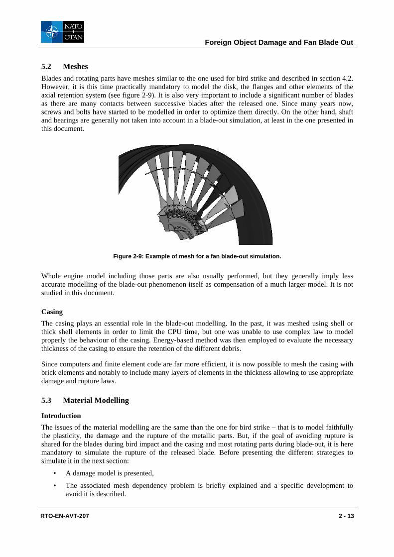
5.2 Meshes Blades and rotating parts have meshes similar to the one used for bird strike and described in section 4.2. However, it is this time practically mandatory to model the disk, the flanges and other elements of the axial retention system (see figure 2-9). It is also very important to include a significant number of blades as there are many contacts between successive blades after the released one. Since many years now, screws and bolts have started to be modelled in order to optimize them directly. On the other hand, shaft and bearings are generally not taken into account in a blade-out simulation, at least in the one presented in this document.
Figure 2-9: Example of mesh for a fan blade-out simulation.
Whole engine model including those parts are also usually performed, but they generally imply less accurate modelling of the blade-out phenomenon itself as compensation of a much larger model. It is not studied in this document.
Casing The casing plays an essential role in the blade-out modelling. In the past, it was meshed using shell or thick shell elements in order to limit the CPU time, but one was unable to use complex law to model properly the behaviour of the casing. Energy-based method was then employed to evaluate the necessary thickness of the casing to ensure the retention of the different debris.
Since computers and finite element code are far more efficient, it is now possible to mesh the casing with brick elements and notably to include many layers of elements in the thickness allowing to use appropriate damage and rupture laws.
5.3 Material Modelling
Introduction The issues of the material modelling are the same than the one for bird strike – that is to model faithfully the plasticity, the damage and the rupture of the metallic parts. But, if the goal of avoiding rupture is shared for the blades during bird impact and the casing and most rotating parts during blade-out, it is here mandatory to simulate the rupture of the released blade. Before presenting the different strategies to simulate it in the next section:
• A damage model is presented,
• The associated mesh dependency problem is briefly explained and a specific development to avoid it is described.
Foreign Object Damage and Fan Blade Out
2 - 14 RTO-EN-AVT-207
Damage Model Damage coupled to plasticity is an easy way to model properly the degradation of the material properties and at least the rupture of the material. It is generally defined by a variable D increasing from 0 for a sane material to 1≤cD for a fully-damaged one. Several models exist to traduce the damage evolution. The damage evolution law we decide to use is or is close to the Lemaître and Chaboche damage evolution law [13], which can be written the following way:
DDD
vm
H
sc
c
−⎟⎟⎠
⎞⎜⎜⎝
⎛Ω
−=
1λ
σσ
εε
&&
where Dc, εc and εs are respectively the critical damage, the critical equivalent plastic strain and the threshold one. λ corresponds to the plastic multiplier and Ω is a function allowing to take into account
effect of the triaxiality rate vm
H
σσ
. Its most classical form is:
( ) ( )2
213132
⎟⎟⎠
⎞⎜⎜⎝
⎛−++=⎟⎟
⎠
⎞⎜⎜⎝
⎛Ω
vm
H
vm
H
σσ
ννσσ
With this damage evolution law, when the triaxiality rate (and hence the function Ω) is constant during the whole test, the damage evolves linearly from 0 for an equivalent plastic strain equal to εs to Dc for an equivalent plastic strain equal to εc. Several tests are necessary to identify the parameters of this law, among other simple traction tests on notched bar.
Mesh Dependence and Damage Model with Delay Effect
Classical damage models used in numerical analysis suffer from mesh dependency and usually lead to an artificial strain localization (into a single element). The delayed damage model, first introduced by Allix and al. [14] for composite laminates and subsequently by Suffis and al. [15] for metals, has proved to avoid this mesh dependency.
The mesh dependency manifests itself when a simulation is performed with several meshes of different refinement. The damage tends to localize randomly depending on the mesh nature and there is no convergence whatever the mesh size. In the mean time, one can observe that the damage rate tends toward infinity, which is non-physical as the physical phenomena at the source of the damage as micro-crack propagation velocity or void growth rate are themselves limited in time.
Some authors suggest to smooth the damage or the plasticity on a zone characterized by a typical length. These methods are called non-local and are already implemented in many finite element code, but they present the main disadvantage to be very costly in CPU time. At the opposite, the delayed damage model is purely local and suggests to use in a way a smoothing in time.
The implementation of a delay effect into the model requires minor modifications into the model used. All one has to do is to rewrite the damage evolution law (see previous sub-section) used in the model without delay effect to determine what is called non-corrected damage Dnc.
DD
Dvm
H
sc
cnc −⎟⎟
⎠
⎞⎜⎜⎝
⎛Ω
−=
1λ
σσ
εε
&&
Foreign Object Damage and Fan Blade Out
RTO-EN-AVT-207 2 - 15
The non-corrected damage evolves the same way than the damage without delay effect, but it is not bounded by the critical damage Dc. Then, the damage with delay effect, which is the one actually taken into account to represent the local damage and to calculate the non-corrected damage rate, is determined using the following equation:
( )[ ]( )DDaD ncc
−−−= ,0maxexp11τ
&
The coefficient a and the characteristic time τc are the two additional parameters of the model. Whereas the damage rate without delay effect can tend toward infinity, the delay damage model introduces a
limitation of the damage rate (which is indeed bounded by cτ
1). Consequently, the damaged zone remains
constant whatever the mesh size. Additional works [16] have also demonstrated that a characteristic length can be associated to the delay damage model as the non-local model.
Spall fracture experiment is used to identify the two additional parameters [17]. They indeed put the influence of the loading time on the spall stress on a prominent place and it was shown that the additional delay effect could reproduce this phenomenon. Conversely, that makes possible by fitting the experimental result the identification of the two parameters.
5.4 Simulation Steps
As for bird strike simulation, several steps are needed to perform a blade-out simulation:
• The first one is dedicated to taking into account the inertial effect in the rotational part. This step is similar to the pre-stress described in section 4.4.
• A second step is dedicated to the blade-out strictly speaking. Depending on the data available, three strategies which are described hereafter can be employed:
• A strategy where the rupture of all parts is modelled thanks to the damage model,
• A strategy using pre-programmed fragmentation lines for the released blade,
• A mix of these two strategies.
Fragmentation Strategy
Depending on the data available, different strategies are possible to model the fragmentation of the released blade. In the most common case, simulations are performed before the engine test and one must use a damage model to determine by simulation the different fragments of the released blade. However, this method leads to smaller fragments than in reality as the fully-damaged elements are erased from the mesh. It is so sometimes more convenient to determine from a first simulation with a damage model the main fragmentation lines and the associated times of rupture and then to replay the simulation using pre-programmed fragmentation lines. At the opposite, when simulations come after the test to explain and to analyse it, it seems better to determine from the test itself the fragmentation lines and to evaluate the associated times of rupture.
Blade-Out
The pre-stress data are used as initial conditions and the appropriate sections are brought in rotation. The released blade is cut initially at its root to simulate the release. Except possibly the released blade,
Foreign Object Damage and Fan Blade Out
2 - 16 RTO-EN-AVT-207
all other parts (blades, casing, etc.) are modelled thanks to rate dependent plasticity coupled with damage model. Contacts are also defined between all parts.
The simulation is then performed for few milli-second, corresponding to one half to one full turn of the engine. The released blade then breaks and impacts the adjacent blade and the casing, leading to:
• Plastic deformation, damage and possibly rupture of the following blades and of the casing,
• Important flexion and other movements (notably advance toward the front of the engine) of the adjacent blade, which makes necessary the study of the load in the disk and in the axial retention system.
It is not necessary to perform a damping simulation as for the bird strike as all results are obtained from this simulation. It is so possible to:
• Verify that the casing is able or not to contain all fragment and hence to optimize the thickness and the mass of the casing,
• Guarantee the non-loss and evaluate the level of damage of the following blades after the blade-out,
• Study the behaviour and the integrity of the axial retention system and hence to optimize the design,
• Analyse the behaviour of other parts as platform.
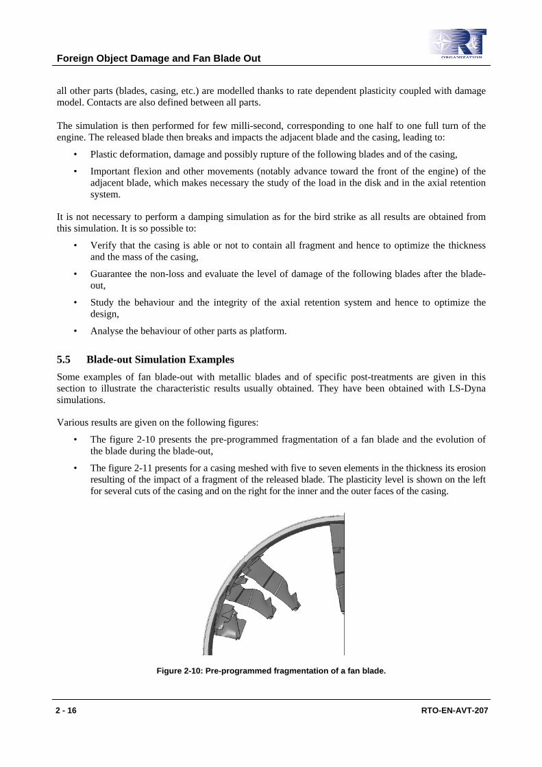
5.5 Blade-out Simulation Examples Some examples of fan blade-out with metallic blades and of specific post-treatments are given in this section to illustrate the characteristic results usually obtained. They have been obtained with LS-Dyna simulations.
Various results are given on the following figures:
• The figure 2-10 presents the pre-programmed fragmentation of a fan blade and the evolution of the blade during the blade-out,
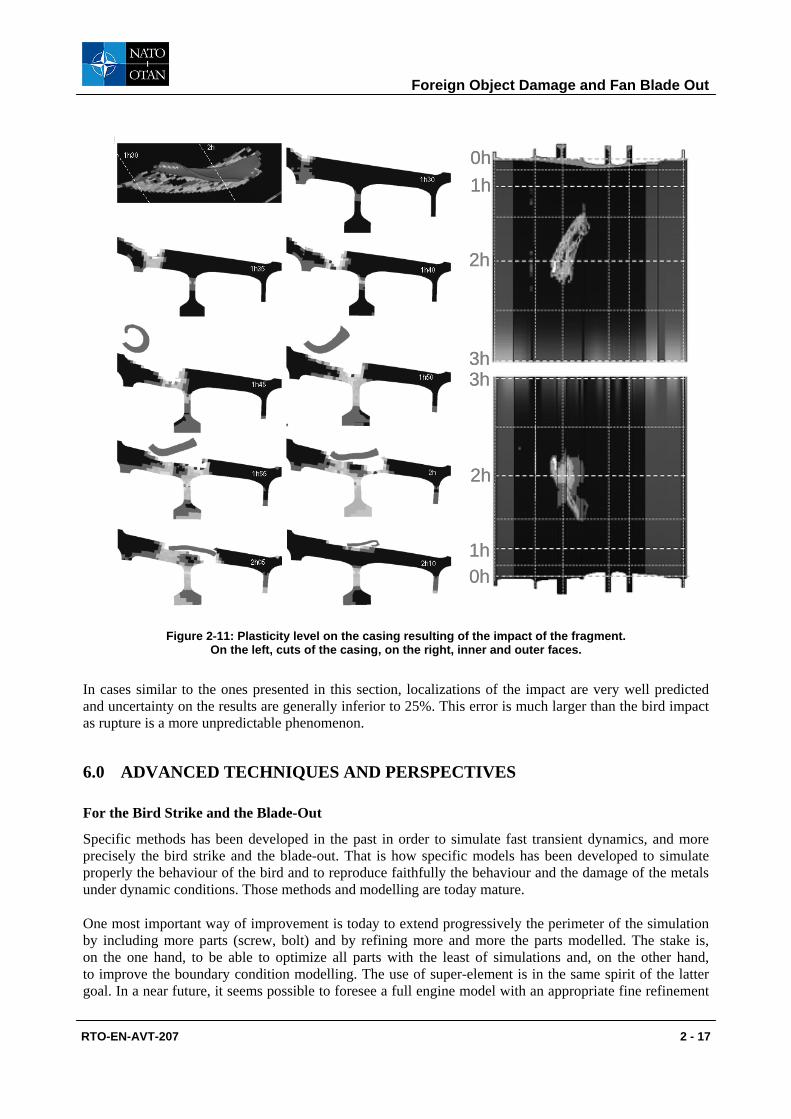
• The figure 2-11 presents for a casing meshed with five to seven elements in the thickness its erosion resulting of the impact of a fragment of the released blade. The plasticity level is shown on the left for several cuts of the casing and on the right for the inner and the outer faces of the casing.
Figure 2-10: Pre-programmed fragmentation of a fan blade.
Foreign Object Damage and Fan Blade Out
RTO-EN-AVT-207 2 - 17
0h
0h1h
1h
2h
2h
3h3h
0h
0h1h
1h
2h
2h
3h3h
Figure 2-11: Plasticity level on the casing resulting of the impact of the fragment. On the left, cuts of the casing, on the right, inner and outer faces.
In cases similar to the ones presented in this section, localizations of the impact are very well predicted and uncertainty on the results are generally inferior to 25%. This error is much larger than the bird impact as rupture is a more unpredictable phenomenon.
6.0 ADVANCED TECHNIQUES AND PERSPECTIVES
For the Bird Strike and the Blade-Out
Specific methods has been developed in the past in order to simulate fast transient dynamics, and more precisely the bird strike and the blade-out. That is how specific models has been developed to simulate properly the behaviour of the bird and to reproduce faithfully the behaviour and the damage of the metals under dynamic conditions. Those methods and modelling are today mature.
One most important way of improvement is today to extend progressively the perimeter of the simulation by including more parts (screw, bolt) and by refining more and more the parts modelled. The stake is, on the one hand, to be able to optimize all parts with the least of simulations and, on the other hand, to improve the boundary condition modelling. The use of super-element is in the same spirit of the latter goal. In a near future, it seems possible to foresee a full engine model with an appropriate fine refinement
Foreign Object Damage and Fan Blade Out
2 - 18 RTO-EN-AVT-207
for the parts studied in this document. New methods as multi-domain methods which allow to couple implicit and explicit domains, structural and modal domains or domains with different step time contribute actively to this goal.
For Similar Applications
Some applications use similar methodologies of the one presented in this document. The main of them are:
• The ice ingestion. In this instance, the main challenge is the appropriate modelling of the ice. At present, an SPH element with an appropriate behaviour law is developed in order to perform ice ingestion on different type of blade.
• The contact between rotor and stator which leads to HCF rupture. Proper modelling of the contact, which includes fine modelling of the abradable, is in course.
• The turbine blade-out whose simulation is very near of the fan blade-out. It is however more complex as:
• Material used for the blade are mono-crystal one,
• Thermal environment has to be taken into account,
• It is essential to model properly the cooling system requiring so a very important number of elements.
However, other applications such as the blade-shedding overspeed protection on turboshaft engines [18] [19] require to model the separation of all the blades of one or more rotors, with a large amount of impacts on the stators. Specific subjects have then to be addressed, such as:
• The identification of material properties at high temperatures
• Modelling of the blades rupture without erosion in order to prevent the blades from “vanishing”.
• Being able to take into account the variety of blade rupture scenarios in the design.
• Simulation of the engine stop while crossing “critical” rotor speeds (rotor dynamics).
• Getting a good balance between simulation costs (time, licences, hardware) and the information provided by the simulation.
7.0 CONCLUSION
As a global conclusion, this document has presented the basis of fast transient dynamics and the methodologies used in order to perform the simulation of a bird strike and a fan blade-out simulations. Two specific key points has been developed, in this case the SPH methodology and the damage with delay effect, which are essential for our modelling. Finally, the current development and some related applications have been listed, allowing one to draw the next improvement in fast transient dynamic. Another field not exposed in this document is the equivalent simulations for other technologies of blades, which require as well adapted methodologies and modelling.
8.0 REFERENCES
[1] Newmark W. (1959) “A method of computation for structural dynamics”, J. Engng. Mech. Div. ASCEI, Vol. 85, pp. 67–94.
[2] Gérardin M. and Rixen D. (1993) “Théorie des vibrations. Applications à la dynamique des structures”, Masson Eds, in French.
Foreign Object Damage and Fan Blade Out
RTO-EN-AVT-207 2 - 19
[3] Hugues T. J. R. (1987) “The finite element method, linear static and dynamic finite element analysis”, Prentice-Hall International Editions.
[4] Combescure A., Lubrecht A. and Suffis A. (2003) “Damage model with delay effect: analytical and numerical studies of the evolution of the characteristics length”, Int. J. of Sol. And Stru., 40:3463–3476.
[5] Suffis A. (2004) “Développement d’un modèle d’endommagement à taux de croissance contrôlé pour la simulation robuste de ruptures sous impacts”, PhD thesis, INSA de Lyon, LaMCoS, in french, France.
[6] Cook W. H. and Johnson G. R. (1983) “A constitutive model and data for metals subjected to large strains, high strain rates and high temperatures”, Seventh International Symposium on Ballistics, The Hague, The Netherlands.
[7] Farré J. and Llorca F. (2002) “Critère de formation de bandes de cisaillement adiabatique et lois de comportement”, Premier Congrès Interdisciplinaire sur les Matériaux en France, Tours, in french, France.
[8] Berthillier M., Bung H., Galon P. and Letellier A. (1997) “Bird impact on fan blade analysis using SPH method coupled with finite element”, Symposium on Structures under Extreme Loading Conditions, Orlando, USA.
[9] Letellier A. (1996) “Contribution à la modélisation d’oiseaux sur les aubes des réacteurs”, PhD, Université d’Evry, in french, France.
[10] Lacome J. L. (1998) “Analyse de la Méthode SPH. Application à la Détonique”, PhD, INSA de Toulouse, in french, France.
[11] Wilbeck J. (1978) “Impact behaviour of low strength projectiles”, Technical Report, pp. 77–134, Air Force Material Laboratory, Wright-Patterson Air Force Base, Ohio 45433, USA.
[12] Barber J. and Wilbeck J. (1978) “Bird impact loading”, The shock and vibration bulletin, Vol. 48, Part 2, pp. 115–122.
[13] Chaboche J. L. and Lemaître J. (1996) “Mécanique des matériaux solides”, Dunod Ed., in french.
[14] Allix O., Deu J. F and Ladeveze P. (1999) “A delay damaged meso-model for prediction of damage and fracture of laminated subjected to high rates loading”, ECCM99.
[15] Suffis A. (2004) “Développement d’un modèle d’endommagement à taux de croissance contrôlé pour la simulation robuste de ruptures sous impact”, PhD thesis, INSA de Lyon, LaMCoS, in french, France.
[16] Suffis A., Combescure A. and Lubrecht A. (2003) “Damage model with delay effect: analytical and numerical studies of the evolution of the characteristics lenght”, Int. J. of Sol. and Stru., 40 :3463-3476.
[17] Suffis A., Combescure A. and Bung H. (2004) “Modèle d’endommagement à effet retard. Identification des paramètres”, Colloque National MECAMAT, Aussois 2004, 501-504, in french, France.
Foreign Object Damage and Fan Blade Out
2 - 20 RTO-EN-AVT-207
[18] Herran M., (2010) “Analyse et simulation du phénomène de perte de pales généralisée sur un turbomoteur d’hélicoptère”, PhD thesis, INSA de Lyon, LaMCoS, in french, France.
[19] M. Herran, H. Chalons, D. Nélias, and R. Ortiz. (2008) “Modelling the impact of a blade on a shield during a blade shedding”. In Proc. of the Vibrations, Choc and Bruit Congress, Ecully, France, June 2008.