Embed Size (px)
Citation preview

GUIDE TO FOREST ROAD ENGINEERING IN MOUNTAINOUS TERRAIN
Forestry Harvesting and Engineering Working Paper 2

Forewordi
Forest Harvesting and Engineering Working Paper 2
GUIDE TO FOREST ROAD ENGINEERING IN
MOUNTAINOUS TERRAIN
by
R. Jonathan FanninUniversity of British Columbia
Vancouver, Canada
and
Joachim LorbachForest Products Service (FOIP)
FAO Forestry DepartmentRome, Italy
FOOD AND AGRICULTURE ORGANIZATION OF THE UNITED NATIONSRome, 2007

The designations employed and the presentation of material in this information product do not imply the expression of any opinion whatsoever on the part of the Food and Agriculture Organization of the United Nations concerning the legal or development status of any country, territory, city or area or of its authorities, or concerning the delimitation of its frontiers or boundaries.
All rights reserved. Reproduction and dissemination of material in this information product for educational or other non-commercial purposes are authorized without any prior written permission form the copyright holders provided the source is fully acknowledged. Reproduction of material in this information product for resale or other commercial purposes is prohibited without written permission of the copyright holder. Applications for such permission should be addressed to:ChiefElectronic Publishing Policy and Support BranchInformation DivisionFAOViale delle Terme di Caracalla, 00153 Rome, Italyor by email to: [email protected]
© FAO 2007

Forewordiii
FOREWORD
A forest management plan is a strategic document that guides both the development and the implementation of forestry practices on the ground. The objective is simple, namely to provide for practices that are safe, productive and environmentally sound. Yet its formulation is challenging. Expectations of forest resources management have evolved tremendously in recent years. The result is a demand for greater consultation, and a more integrated approach to planning that includes cultural, ecological, economic and social factors. This publication has been prepared in response to that demand. Its primary objective is to describe recommended practices for forest road engineering in mountainous terrain, with emphasis on how management objectives for the area under the strategic plan are to be met by the proposed road locations.
The information in this guide to forest road engineering on mountainous terrain has been compiled with the basic intent of disseminating practices that address concerns for timber production, forage production and grazing, recreation and tourism, water, fisheries, wildlife and biodiversity and cultural heritage. As such, the guide will be of use to foresters, biologists, ecologists, engineers, logging specialists and social scientists. It will allow policy-makers to develop or refine national, regional and local codes of practice with reference to a coherent framework for decision analysis.
Recommendations in the guide have been compiled with reference to best management practices, the basics of sound engineering practice, and a critical evaluation of field experience from case studies reported in the literature. The original scope of the FAO Guide to Forest
Road Engineering in Mountainous Terrain was established at an international workshop convened to identify opportunities for improved strategic planning, given the nature of current practices and evolution of emerging demands. A draft of the guide was prepared and circulated to leading experts, for review and discussion. Consequently, this final version is a compilation of knowledge from FAO member countries, research institutes, non-governmental organisations and the private sector.
The guide is not a stand-alone document. Rather, it is intended as a companion to the FAO Model Code of Forest Harvesting Practice, which was written to improve standards of utilisation and reduce environmental impacts. As such, a specific intent of the guide is to focus on considerations that influence forest road engineering, within the broader context of forest resources management and with application to mountainous terrain. It is also intended to complement work of the FAO on sustainable mountain development, for which responsibilities were assumed following the United Nations Conference on Environment and Development (UNCED), as a contribution to the International Year of the Mountain in 2002.
Wulf Killmann Director
Forestry Products and Industries Division FAO Forestry Department


vContents
CONTENTS
Foreword iii Acknowledgements iv Contents v
CHAPTER 1 - INTRODUCTION 1 Forest harvesting on steep ground 1 Purpose 3 Scope 4
CHAPTER 2 - STRATEGIC PLANNING 7 What it is 7 Guiding principles 7 Objectives 8 Potential consequences of inadequate strategic planning 8 Recommended practices 8 Road impacts in tropical countries 13
CHAPTER 3 - ACCESS PLANNING 15 What it is 15 Guiding principles 15 Objectives 17 Potential consequences of inadequate access planning 17 Recommended practices 17 Factors influencing road alignment 16
Geometric controls on road alignment 17
Observations during road layout 18
Guidelines on cut slope and fill slope angles 18
Guidelines on swell and shrinkage of materials 20
Cost estimation 20
The road paradox 23
CHAPTER 4 - ROAD PAVEMENT 27 What it is 27 Guiding principles 27 Objectives 29 Potential consequences of an inadequate road pavement 29 Recommended practices 31 Corrugation and surface ruts 28

viForest road engineering in mountainous terrain
Geosynthetics 28
Stabilization by soil mixing 30
Dust palliatives 30
CHAPTER 5 - DRAINAGE 37 What it is 37 Guiding principles 37 Objectives 39 Potential consequences of inadequate drainage provisions 39 Recommended practices 41 Selection of pipe culvert 44
Culvert size 44
Guidelines on cross-drainage (culvert) spacing 46
Fish passage 46
Road drainage 49
Potholes 49
CHAPTER 6 - EQUIPMENT SELECTION 51 What it is 51 Guiding principles 51 Objectives 51 Potential consequences of inadequate equipment selection 51 Recommended practices 53 Notes on hydraulic excavators 53
Notes on rock drills 56
Unit costs 56
Machine rates 56
CHAPTER 7 - ROAD CONSTRUCTION 59 What it is 59 Guiding principles 59 Objectives 61 Potential consequences of inadequate road construction 61 Recommended practices 61 Changes in design during construction 62
Endhauling operations 62
CHAPTER 8 - SLOPE PROTECTION AND STABILIZATION 69 What it is 69 Guiding principles 69 Objectives 71 Potential consequences of inadequate slope protection 71 Recommended practices 72 Bioengineering techniques and protective functions 70

viiContents
CHAPTER 9 - ROAD MAINTENANCE 77 What it is 77 Guiding principles 77 Objectives 77 Potential consequences of inadequate road maintenance 79 Recommended practices 79
GLOSSARY 81
APPENDIX 83
BIBLIOGRAPHY 85

Forest road engineering in mountainous terrainviii
ACKNOWLEDGEMENTS
Many sources of information have been used in preparing the FAO guide to forest road engineering in mountainous terrain. Those sources include various national and subnational codes of forest practice, most notably the comprehensive Forest Practices Code of British Columbia, Canada.
Several individuals contributed to the formation and development of this work, including the experts who attended the FAO workshop to prepare a statement of needs and those who provided detailed review comments on our initial draft, all of whom are listed in an appendix to the document. We give particular acknowledgement to Nikolaus Fernsebner and Dirk Jaeger, for their extensive contributions to the draft chapters on access planning and drainage provisions, respectively.
Additional and extensive information has been compiled from forest engineering manuals, case-study reports and specialist conference proceedings on new and innovative practices. The contribution of librarians at the FAO Forestry Department to locating many of these texts was invaluable, and is gratefully appreciated. María Guardia saw to the coherence of graphic design and layout of the document.

Forewordix
ABBREVIATIONS
ATIBTAssociation Technique Internationale des Bois Tropicaux, Paris, France
BCMoFBritish Columbia Ministry of Forests, Victoria, British Columbia
FAOFood and Agriculture Organization of the United Nations, Rome, Italy
FERICForest Engineering Research Institute of Canada, Vancouver, British Columbia, and Pointe Claire, Quebec, Canada
GTZGerman Agency for Technical Cooperation, Eschborn, Germany
ILOInternational Labor Organization, Geneva, Switzerland
LIROLogging Industry Research Organization, Rotorua, New Zealand
NMANorwegian Ministry of Agriculture, Oslo, Norway


1Introduction
CHAPTER 1 INTRODUCTION
This guidance is written for practitioners, whose responsibilities include that of road access on steep ground, to assist with the development of improved professional practices in forest road engineering that are consistent with the basic principles of sustainable forest management. More specifically, it is written to promote the use of recommended practices in the planning, design, construction and maintenance of forest roads in mountainous terrain. The recommendations are drawn from best practices that have proven effective in minimizing the adverse impacts of forest roads. They include reference, where appropriate, to case studies describing forest operations on steep and potentially unstable ground that are used to illustrate key points.
The publication is intended primarily for engineers, foresters, technicians, consultants and government regulators with experience of forest access planning. It contains guidance on both strategic and access planning, road and drainage design, equipment selection, construction techniques, protective works and maintenance. The prime intent is to refine the current standards of practice that govern activities in road engineering.
In general, guidance on forest operations is prepared for one of two reasons. Either it is provided to interpret mandatory codes of practice arising from legislated regulations or, alternatively, it is provided to describe voluntary activities that, if adopted, could reasonably be expected to yield improvements to professional practice. The intent of each provision, whether mandatory or voluntary, is similar and the principal difference lies only in the method of implementation. This guidance is written for the latter purpose, namely to describe voluntary activities that experience suggests will encourage forest operations that are environmentally sound, socially acceptable and economically viable. These are three prerequisites for sustainable forest development. In promoting the use of recommended practices, the main focus of the FAO guide to forest road engineering in mountainous terrain is to refine the practitioner’s understanding of potentially adverse impacts and to use that enhanced knowledge in a broader consideration of the socio-economic factors influencing management of the forest resource.
FOREST HARVESTING ON STEEP GROUND A critical issue to the advance of environmentally sound forest practices, especially on steep ground, is an appropriate system for the planning, control and evaluation of harvesting operations. A system that is used with diligence, and is appropriate to the terrain in which it is applied, has the potential both to reduce environmental impacts and improve the socio-economic benefits of the forest resource to the

2Forest road engineering in mountainous terrain
community. Forest roads are widely recognized as the major source of disturbance in any forest development. The alignment of the road generates a series of alternating cuts and fills which, in turn, change the natural profile of the slope and hence the potential for instability. The alignment of the road also tends to modify the existent pattern of surface and groundwater drainage on the slope, which also influences the potential for instability. Consequently, the likelihood of soil erosion and landslide activity increases following road construction.
Road access in mountainous terrain
Within the context of harvesting operations, forest road engineering involves “the specification of design standards and the engineering design, field layout, construction and maintenance of the roads and subsidiary structures such as bridges and culverts” (Dykstra and Heinrich, 1996). The responsibility for planning and design should rest with forest engineers who have a clear understanding of the interdisciplinary demands placed upon them. Thereafter, the construction and maintenance of forest roads should be supervised by qualified engineers or foresters and completed by experienced work crews. Various factors should be considered, which include but are not limited to:
• cultural • ecological • economic • environmental • safety • social In this context, forest roads for which the planning, design, construction and
maintenance have been properly undertaken should: • avoid disturbing areas of significance for historical or archaeological reasons,
or religious or community purposes
K. TU
RN
ER, B
CM
OF

3Introduction
• account for wildlife and fisheries needs, together with any concerns for flora and fauna
• provide a cost-effective access for purposes of harvesting and transportation, and for the long-term management of the resource
• protect against unacceptable levels of soil erosion, landslide activity and degradation of natural water flow and water quality
• ensure the safety of forest workers and the general public • fit with the visual qualities of the landscape, and associated recreation and
tourism A growing expectation that many, if not all, of these various factors are met in
current forest practices has provided an impetus to the writing of this guidance.
PURPOSE The FAO guide to forest road engineering in mountainous terrain is written primarily as a reference for FAO member countries that do not have a code of forest practices or, in the absence of any code, a series of appropriate voluntary provisions. Although considerable progress has been made in the development and implementation of environmentally sound harvesting practices in recent years, opportunities still exist for improvement in many aspects of routine operations. The main purpose of the guidance therefore is to promote activities that refine current standards of practice and limit adverse environmental impacts, thereby enhancing the protection and sustainable management of forest resources.
Road construction, of all forest operations, has one of the greatest potentials to impose a lasting and often irreversible environmental impact on the landscape. Yet it is necessary in order to gain access to the timber, both for harvesting and for subsequent silvicultural treatment. Therein lies the challenge. Given the diversity
K. FA
IRH
UR
ST
Fit with the visual qualities of the landscape, and associated recreation and tourism

4Forest road engineering in mountainous terrain
of factors for consideration, the challenge often requires an interdisciplinary approach be adopted in planning. It may also be appropriate to seek specialist advice on issues of wildlife and fisheries, geotechnics and hydrotechnics, and conservation and landscape management in particular situations.
Variations in practice will exist between different countries and locations. Therefore, it is reasonable to expect that some recommendations described in this guidance are not universally applicable. Accordingly, the underlying purpose of the guidance is to compile a source of information to which practitioners can refer when called upon to make decisions in forest road engineering.
SCOPE The FAO guide to forest road engineering in mountainous terrain addresses engineering practices related to the specific challenges that govern road access on steep ground. More general guides are usually broader in scope, with less emphasis on specific practices, and include recommendations for other types of ground condition. In contrast, technical manuals on forest road engineering usually report step-by-step design procedures together with details of computational methods for use in analysis. This guide is not intended to repeat those procedures and methods. Rather, the focus of recommendations is intentionally limited to steep ground, where poor or inappropriate practices have the greatest potential for adverse impact and where any necessary remedial works are most difficult to enact successfully. The guidance addresses the four major activities in forest road engineering, namely:
• planning, in which both strategic and operational recommendations are established to meet the overall environmental, economic, and social objectives of the proposed operation, with provisions incorporated to address ecological impacts and cultural issues
• design, in which the expected standards of a safe road alignment are established with reference to available field data, suitable construction materials identified, and potentially unstable terrain identified for more detailed assessment
• construction, in which the alignment is first pioneered and subsequently established, with adequate provisions made for drainage and potentially unstable slopes
• maintenance, in which the condition of the road is kept to a suitable standard The guide addresses, sequentially, topics of strategic (or integrated) planning,
access (or operational) planning, the road pavement and drainage, use of equipment, construction methods, slope protection and stablilisation, and road maintenance. Each chapter follows the format of the companion FAO model
code of forest harvesting practice, in which the subject is first defined, the guiding principles articulated, and the objectives then established. Following a description of the potential consequences of improper activities, a series of recommended practices is then provided with reference, where appropriate, to case studies in mountainous terrain.

5Introduction
Ensure the safety of forest workers and the general public
J. SCH
WA
B, B
CM
OF


7Strategic planning
CHAPTER 2 STRATEGIC PLANNING
WHAT IT IS A strategic plan, or forest management plan, guides the overall development and implementation of forestry practices on the ground. It shows the proposed road network and harvest systems for a specific area or concession, and explains how the elements fit together over time in order to minimize costs, maintain safety, and mitigate the impacts of those practices on the diversity of forest resources. Preparation of the strategic plan should take into account expectations and requirements for management of the forest resources, either issued by government or, where appropriate, identified through a participatory process involving the public and other stakeholders. These management objectives may include one or more of the following:
• timber and fuelwood production • forage production and grazing • recreation and tourism • water, fisheries, wildlife and biological diversity • cultural heritage
A strategic plan facilitates safe, productive operations that are environmentally sound. A good plan, which is properly implemented, allows responsible decisions to be made with reference to accurate information. As such, strategic planning requires an integrated approach. The plan should address all factors that influence the location and scheduling of road construction and the harvest units to which access is provided. As a separate matter, a detailed analysis and design of proposed roads should be reported in an access plan, which is addressed in the next chapter. In contrast, the strategic plan provides information on resource values of the forest throughout the planning area. That information should be conveyed in maps, text and tables. The plan should also describe forest practices to ensure the maintenance of a productive site.
GUIDING PRINCIPLES Strategic planning is undertaken to develop a series of forest operations and resource management activities that conform to general management objectives for the development area. The critical forest operations are road construction and timber harvesting. The designated objectives will likely address issues, at both a regional and local level, which include cultural, ecological, economic,

8Forest road engineering in mountainous terrain
environmental, safety and social factors. Therein lies the need for an integrated planning team that may include foresters, biologists, ecologists, engineers, logging specialists and social scientists. Social factors can be diverse, and include use of the forest road network for purposes of encroachment and settlement, provision of non-wood products to market, hunting and recreation.
As a general requirement, the plan should cover the entire area affected by road construction and timber harvesting, and span a minimum period of time (at least 10 years). It should state the general management objectives for the forest resources, and strategies for known resource features and values such as cultural heritage sites, wildlife habitat, and special areas. By its very existence, a strategic plan allows for review of new proposals. It also provides an opportunity for approval, conditional approval or rejection of the entire content or portions of the plan.
OBJECTIVES The strategic plan describes how management objectives for the area under the strategic plan are to be met by the proposed forest operations. The plan must include maps that provide a representation of the topography, resources and proposed road construction and harvesting. This provides the public and administrating government agencies with a clear understanding of the forestry and harvesting operations planned in the area, over the time period of the plan.
The strategic plan should: • identify indigenous rights and archaeological sites • show historic or current locations of major pests or disease that represent
a threat to forest health • identify potential impacts on fuelwood and forage production and livestock
management • show how specific biological diversity or ecosystems are to be protected,
either at the landscape level or at the stand level • describe the protection of critical habitat for identified wildlife • describe a spatial pattern of proposed harvesting, with time, for the
duration of the plan • identify the location and type of road construction to be carried out
(primary, secondary or tertiary – permanent or temporary), using a logical naming or numbering system for administrative purposes
• address protective measures for the risk of wildfire, and prescribed fire by controlled burning
• show how forestry operations will be conducted to minimize the impact of landslide activity and to protect, maintain or enhance the long-term productivity of forest soils
• show how streams, wetlands and lakes are to be protected to minimize impacts on water quality and quantity
• for watersheds that have a significant downstream fisheries or domestic water value, or cultivate land, describe how those values are to be protected

9Strategic planning
• minimize harvesting and transport costs by reporting how all timber planned for removal will be accessed
• specify any special requirements for safety of forest workers and the public • delineate other land use activities or alienations (for example, private
property, utility corridors and mineral claims) • identify known scenic areas, and describe measures for the protection of
visual features • show how to protect, or minimize impacts on, recreation resources
POTENTIAL CONSEQUENCES OF INADEQUATE STRATEGIC PLANNING In the absence of a strategic plan for development of an area or concession, the forest operations are likely to result in adverse impacts that are both unnecessary and avoidable. The outcome is a poor coordination of activities, which in turn leads to inadequate control of the operations. Accountability of the resource management suffers as a consequence.
Planning for limited purposes, for example the preparation of a plan for logging operations only, can have similar consequences. It may lead to isolation of timber. It will cause the transportation system to evolve in a piecemeal way, with new roads being located based solely on the needs of individual harvest units, at any point in time, rather than a road network being designed for the needs of the area, over a period of time. The result is often the clearance of more ground for road access than is necessary. Consequently, higher costs of road construction, maintenance and transportation are incurred, and the potential for soil erosion and stream sedimentation is greater.
Show the location of all roads and trails for access to, and within, harvest units as well as
the timing of road construction
J. FAN
NIN

10Forest road engineering in mountainous terrain
Protection of streams, wetlands and lakes to minimize impacts on water quality
RECOMMENDED PRACTICES A strategic plan, by definition, describes the diverse resources of the area under development, and identifies both the location and timing of proposed road construction and harvesting activities within that area. It comprises a document and a series of maps, typically drawn to a scale between 1:10 000 and 1:50 000. Orthophotographs of the terrain may provide very useful information about the relief of the ground. A forest cover map should be used as the base map.
K.TU
RN
ER, B
CM
OF
K. TU
RN
ER, B
CM
OF
Anticipate the adverse impacts of slope instability

11Strategic planning
The document is the main source of information on the strategic plan, much of which is illustrated on the maps. Recommended practices for the preparation of a strategic plan are as follows:
• consult with appropriate representatives on issues of indigenous peoples’ rights, the impact of access on archaeological sites, and options for resolution of adverse impacts
• identify the extent and nature of any pest infestations (for example susceptible or unhealthy stands) from a forest health survey
• describe the impact of proposed activities on the travel patterns of livestock, if any, and migratory wildlife
• describe and locate provisions for management of biodiversity at the landscape level (for example, retention of old growth, species composition, and the temporal and spatial distribution of harvesting) and at the stand level (for example, wildlife habitat)
• provide volume summaries by species and hectares, of areas proposed for logging, over time
• minimize the disturbance caused as a result of access in designated wildlife habitat management areas (for example, no road construction in high sensitivity areas) and by timber harvesting (for example, a non-harvest zone in high sensitivity areas, a selection harvest zone of specified width and maximum percentage stem removal, and harvest scheduling to avoid breeding seasons)
• describe, for each harvest unit, the proposed system (for example, clearcut, selection cut, shelterwood, individual-tree) and proposed method (aerial, cable or ground-based)
• show the location of all roads and trails for access to, and within, harvest units as well as the timing of road construction (for example, year and season)
• show the location of quarries or major borrow pits • show the location of bridges and other major stream crossings • identify natural breaks (for example, rock and waterbodies) and forest
attributes that increase fire resistance • prescribed burns may be used to enhance forest resources (for example, forest
health and wildlife habitat), therefore design the harvested areas to facilitate any need for prescribed burns (for example, limit the size of contiguous disturbed areas, identify fuel hazard areas, and restrict public access)
• identify the type and locations of natural hazards on ground that is unstable (for example, ground with existing landslides) and identify ground that is potentially unstable following road construction and timber harvesting (for example, ground at a slope gradient steeper than 60%)
• assess the likely consequence of these natural hazards (for example, the potential for landslide debris to enter streams and impact water quality or downstream land use)
• for streams, wetlands and lakes that are designated for riparian management, document the type of reserve or buffer zone to mitigate the impact of

12Forest road engineering in mountainous terrain
Management of biodiversity through provisions for wildlife habitat
Identify provisions for wildlife during layout, including designated wildlife trees
M. M
OSSO
P K
.MA
RTIN

13Strategic planning
harvesting (for example, a non-harvest zone of specified width, or a selection harvest zone of specified width and maximum percentage removal of pre-harvest basal area)
• for streams not requiring a reserve zone, provide information on felling, yarding, and debris management
• discuss options to minimize any unacceptable windthrow hazard • assess the cumulative effects of forest practices on watershed hydrology (for
example, changes to peak streamflow and changes to channel morphology in the riparian zone)
• assess the impact of operations on area of special visual quality (for example, areas with outstanding scenic values)
• ensure existing and new recreation resources are identified (for example, sites and walking trails, sensitive areas, rivers and wilderness) and describe measures for their protection (for example, a non-harvest zone of specified width)
• identify roads or areas that will have access restriction (for example, industrial use only)
• describe the administration of access through alienated properties (for example, purchase right-of-way, road use agreements, leases or permits)
ROAD IMPACTS IN TROPICAL FORESTS
A distinction is made between direct and indirect impacts of the road on the forest.
Indirect impacts are a result of the access itself, which facilitates encroachment, clearing
and in-migration, eases constraints to commercial poaching, and encourages illegal
harvesting of timber and non-wood products. New roads, especially those linking
communities, provide fast access to markets. Issues of individual freedom and ancestral
rights often conspire to prevent a timely regulation of these activities, which are related
to social factors. An emerging consensus now recognizes the indirect impacts of road
access to impart a more lasting change than the direct impacts of logging itself.
Strategic planning is therefore an essential prerequisite for responsible management
of all forest resources, based on economically and ecologically viable practices. It must
integrate road access with broader considerations of regional development. A road
network, including skid trails, which is well designed and constructed forms the basis
for sustainable forest practices. Ultimately, strategic planning requires an effective
implementation on the ground, often against opposition from poorly informed or
colluded interests. Too often, the cause of road access that is improperly designed,
constructed and maintained is not so much a shortage of funds for appropriate
equipment, but decisions and working methods that show insufficient awareness
of the adverse impacts on the forest ecosystem. Many of those economic, social and
environmental impacts can be mitigated through participatory planning and sound
engineering practices.
Ref. FAO/ATIBT (1999)
ROAD IMPACTS IN TROPICAL FORESTS
A distinction is made between direct and indirect impacts of the road on the forest.
Indirect impacts are a result of the access itself, which facilitates encroachment, clearing
and in-migration, eases constraints to commercial poaching, and encourages illegal
harvesting of timber and non-wood products. New roads, especially those linking
communities, provide fast access to markets. Issues of individual freedom and ancestral
rights often conspire to prevent a timely regulation of these activities, which are related
to social factors. An emerging consensus now recognizes the indirect impacts of road
access to impart a more lasting change than the direct impacts of logging itself.
Strategic planning is therefore an essential prerequisite for responsible management
of all forest resources, based on economically and ecologically viable practices. It must
integrate road access with broader considerations of regional development. A road
network, including skid trails, which is well designed and constructed forms the basis
for sustainable forest practices. Ultimately, strategic planning requires an effective
implementation on the ground, often against opposition from poorly informed or
colluded interests. Too often, the cause of road access that is improperly designed,
constructed and maintained is not so much a shortage of funds for appropriate
equipment, but decisions and working methods that show insufficient awareness
of the adverse impacts on the forest ecosystem. Many of those economic, social and
environmental impacts can be mitigated through participatory planning and sound
engineering practices.
Ref. FAOFF /A// TITT BT (1999)

14Forest road engineering in mountainous terrain
Describe, for each harvest unit, the proposed system (for example, clearcut, selection cut,
shelterwood, individual-tree) and proposed method (aerial, cable or ground-based)
P. JOR
DA
N, B
CM
OF

15Access planning
CHAPTER 3 ACCESS PLANNING
WHAT IT IS As part of the strategic plan, an access plan should be prepared for both existing and proposed roads that are to be used for timber harvesting operations. The access plan should report details of a road design that is environmentally sound, seeks to minimize harvesting and transport costs, and provides for the safety of forest workers and the public. The plan should report information on the location and scheduling of road construction throughout the planning area. That information should be conveyed in maps, text and tables.
The plan is prepared from a field reconnaissance to: • consider the needs of all potential road-users • study alternative route projections • layout the optimum route as a preliminary alignment • survey the preliminary alignment • design the final alignment The plan may include, as is appropriate, detailed site surveys for any major
stream crossings and bridges. As such, access plans should be prepared by qualified engineers and/or foresters with understanding of the need to limit soil disturbance, and maintain proper drainage.
GUIDING PRINCIPLES Planning of the road network must consider harvesting methods, which determine the requirements for road spacing and hence road density. Forest roads have the potential to be the most problematic feature of timber harvesting operations. Inappropriate design, poor construction, and infrequent maintenance contribute to the potential for soil erosion and its related impacts, for example on water quality. Therefore access planning is undertaken to develop a road network that conforms to general management objectives for the development area. In general, roads should be located outside riparian areas, except for stream crossings, which should be selected to mitigate disturbance to the bank and the channel. In a community watershed, the road should not be located close to any designated water intake. Consideration should be given to avoidance of hazardous terrain, protection of sensitive slopes, and an evaluation of adverse impacts on both water quality and aquatic habitat. Good quality field data, and appropriate ground checking, are essential. Finally, the access plan must be developed in accordance with national laws, regulations and standards.

16Forest road engineering in mountainous terrain
FACTORS INFLUENCING ROAD ALIGNMENT
Maximum uphill grade
Maximum downhill grade
Stopping distance
Sight distance
Sliding- cornering
Overturning -cornering
Off-tracking
Drive axle loads
Braking systems available
Braking systems available
Visual obstruction: horizontal curve
Vehicle speed
Vehicle speed
Trailer type, fifth wheel or pole trailer
Traction coefficient
Axles subject to braking
Axles subject to braking
Visual obstruction: vertical curve
Curve radius Curve radius Curve radius for front axle
Momentum effect
Water cooling of brakes
Loads on axles with braking
Seasonal obstructions (eg. snow banks, brush)
Super-elevation
Super-elevation
Tractor and trailer axle locations
Length of grade
Loads on axles with braking
Coefficient of friction
Travel direction of object to be avoided
Axle loads Vehicle geometry
Axle width
Wheel torque
Coefficient of friction
Reaction time to apply brakes
Coefficient of friction
Weight distribution
Road width
Reaction time if one braking system fails
Vehicle speed
Trailer type, fifth wheel or pole trailer
Over-hanging loads
Length of grade
Travel uphill or downhill
GEOMETRIC CONTROLS ON ROAD ALIGNMENT
The suggested values illustrate alignment controls for average conditions on forest roads,
and will require modification for site conditions and periods of use (seasonal or all-
weather). The minimum stopping sight distance is for single-lane, two-way roads. Note
that two-lane and single-lane one-way roads require half this stopping distance. The
suggested maximum road gradients are provided for purposes of guidance, recognizing
the final recommendation is dependent on site-specific factors.
Road width
(m)
Design speed (km/h)
Min. stopping
sight distance (m)
Min. curve radius (m)
Max. road gradient (%)
Favourable
Adverse
4 to 5 20 40 15 12 to 16(18% for less
than 75m) 9(12% for less than 100m)
5 to 6 30 65 35 10 to 12 (14% for less than 125m) 8 (10% for less
than 100m)
≥ 7 40 95 65 8 (10% for less than 200m) 7 (8% for less
than 100m)
50 135 100
60 175 140
70 220 190
80 270 250
Modified from BCMoF/BCE (2001), NMA (1997) and Heinrich (1987)
17Access planning
OBJECTIVES The access plan describes how management objectives for the area under the strategic plan are to be met by the proposed road locations. The plan must include maps that provide a representation of the topography, type of road (for example, primary “main” roads, secondary “feeder” roads and tertiary “skid trails”), and associated landings, bridges, culverts, stream crossings, quarries and borrow pits. Roads may be classified as either permanent or temporary, depending on needs identified in the strategic plan and on the ability to rehabilitate access at some point in the future. This provides the public and administrating government agencies with a clear understanding of the road construction activities and budgeting requirements for the area, over the time period of the plan, and any intended deactivation of that road access network. Ideally, the primary road should pass through the centre of the timber area.
As a component of the overall strategic plan, the prime focus of the access plan is to address economic, environmental and safety factors, as follows:
• optimize harvesting and transport costs • illustrate the location and type of road construction to be carried out • show how forestry operations will be conducted to minimize the likelihood
of soil erosion associated with roads • describe how streams, wetlands and lakes are to be protected to restrict
impacts on water quality • specify any requirements for user safety Additionally, the access plan should satisfy any special cultural, ecological and
social factors identified in the strategic plan.
POTENTIAL CONSEQUENCES OF INADEQUATE ACCESS PLANNING In the absence of an access plan for development of an area or concession, roads are likely to be unnecessarily expensive to construct and maintain. A particular concern is the unpredictable nature of the costs, and associated uncertainty in the process of tendering for construction. A further economic consequence can be higher transportation costs, as a result of road locations for which the design is less than optimal, yielding a network that is imperfectly fitted to operational needs. Additional recognition must be given to the connection between vehicle performance, and hence operating costs, and the location and alignment of the road.
Adverse environmental impacts of inadequate access planning include excessive soil erosion, increased landslide risk and greater stream sedimentation. The likely consequence of each impact is a loss of forest productivity, water quality and aquatic habitat respectively. Ecologically sensitive sites may also be inadvertently damaged and, at the landscape level, visual qualities may suffer unnecessarily.
RECOMMENDED PRACTICES Access planning, by definition, involves a detailed engineering analysis of
the proposed harvesting methods and road network within the plan area. The

18Forest road engineering in mountainous terrain
OBSERVATIONS DURING ROAD LAYOUT
The following checklist of observations, along the preliminary road alignment, addresses
issues of importance to an engineered design:
• delimit unstable or potentially unstable terrain
• identify road sections on slopes greater than 50% (for a geometric design)
• describe topographic features (for example, a rock outcrop, swamp, source of gravel or
rip rap, disposal site for debris)
• assess the limits of rock designated for ripping or blasting
• identify soil types from exposures and hand-dug pits
• note all continuous and intermittent stream channels, groundwater seeps and very
moist soils
• mark all locations requiring a site plan for design of stream crossings, and drainage
provisions
• identify encroachments on utility corridors or other property (for example, a buried
pipeline or private property)
• recommend clearing widths and construction methods, including provision for disposal
of debris where appropriate
Modified from BCMoF/BCE (2001)
GUIDELINES ON CUT SLOPE AND FILL SLOPE ANGLES
Cut slope (< 5m) Fill slope
Material typeMaximum slope angle (H:V) Material type
Maximum slope angle (H:V)
Coarse-grained soils
Loose to compact, sands or sands and gravels
1.5H:1V
Compact to dense, silty sands
1H:1V Sand, sand and gravel and most silty sand and gravel
1.5H:1V
Dense to very dense and cemented, silty sand and gravel
0.75H:1V
Fine grained soils
Soft silts or silty clay 1.5H:1V
Hard silts, silty clays or clays
1H:1V Silts or clays Not recommended, unless specific drainage provisions
Rock Strong, solid Vertical or rock flatter to suit rock structures
Placed (not dumped) coarse angular fill or rip-rap
1H:1V
Modified from BCMoF/BCE (2001)

19Access planning
outcome of that analysis, at each location, is a specification for the horizontal and vertical alignment of the road centreline. Plan and profile drawings of this final alignment include all information pertinent to construction of the road. The geometric design of the centreline alignment is developed from survey data for a preliminary alignment, which itself is selected as the preferred road location from alternative route projections identified in a reconnaissance. It is important the designer walk along the road corridor before and after the design work to confirm the final alignment and minimize the need for changes during construction.
The field reconnaissance that is the basis for a geometric design should give consideration to each of the following elements. Firstly, in a study of alternative route projections:
• assemble information covering the area (for example, aerial photographs and topographic maps at a preferred scale of 1:5000)
• recognize that, for the case of topographic maps produced from aerial photographs, the process of photo-interpretation can yield limitations to accuracy on forested ground
• note points through which the road should pass (control points) that are considered to be advantageous (for example, preferred stream crossings, or relatively flat areas for switchbacks), and avoid those that are problematic (for example, natural barriers like excessively steep ground, or rock bluffs)
• roads should have a minimum grade (for example, 2%) to provide for drainage • roads should have a maximum grade that is determined by factors including
direction of travel (uphill or downhill), mode of operation (loaded or unloaded vehicle), distance over which the grade is sustained (short or long), vehicle type (power/weight ratio, powered axles), traction on the road surface, season of use and traffic frequency
• for the case of a “favourable” grade (downhill travel, with vehicle loaded), short distances of maximum grade should be followed, or else preceded, by a gentle gradient
• experience suggests that variations in gradeline tend to mitigate the problems of erosion that can occur on long, straight and continuous grades
• switchbacks (hairpin bends) are to be avoided, if possible, since they take up a considerable amount of productive land, are expensive to construct, and detract from the visual quality of a landscape
• by inspection, identify all of the reasonable alternative routes • select a preliminary alignment of the road, which is by definition the
optimum route location given all of the alternative projections In a layout of the preliminary alignment: • ground-check the preliminary road location, and mark the route (for
example, with flagging tape or stakes) in preparation for a field survey • the route should be established using stations that are closely-spaced (for
example, up to 15m apart in rock and up to 30m apart in other materials), and at major topographic features, to facilitate calculation of volumes of cut and fill for mass-haul purposes

20Forest road engineering in mountainous terrain
GUIDELINES ON SWELL AND SHRINKAGE OF MATERIALS
Material type Initial
Conditions Conversion factors-convert to:
Bank Loose Compacted
Coarse grained soils Clean sand Bank 1.00 1.12 0.95
Loose 0.89 1.00 0.85
Compacted 1.05 1.18 1.00
Mixed soil Bank 1.00 1.25 0.90
Loose 0.80 1.00 0.72
Compacted 1.11 1.39 1.00
Fine grained soils Clayey silt Bank 1.00 1.30 0.90
Loose 0.77 1.00 0.69
Compacted 1.11 1.44 1.00
Rock Ripped Bank 1.00 1.30 1.00
Loose 0.77 1.00 0.77
Compacted 1.00 1.30 1.00
Blasted Bank 1.00 1.40 1.15
Loose 0.71 1.00 0.82
Compacted 0.87 1.22 1.00
Modified from BCMoF/BCE (2001)
COST ESTIMATION (COMPILED WITH REFERENCE TO FAO, 1992)
Activity Unit cost Comment
Site preparation
Site facilities lumpsum transport of machinery
Felling and clearing costs/m3 not considered if wood sold
Earthwork (subgrade)
Earthwork costs/m3 or costs/m including haul < 50m
Mass-haul costs/m3 or costs/m haul ≥ 50m
Bedrock costs/m3 or costs/m
Slope construction costs/m2 or costs/m
Slope protection costs/m2
Drainage
Ditches costs/m
Culverts costs/m
Fords lumpsum
Pavement (base course and surface course)
Gravelling costs/m3 or costs/m material, haul and placement
Grading costs/m
Compacting costs/m
Geosynthetics costs/m2 or costs/m
Structures
Retaining wall lumpsum
Bridge (incl. abutments) lumpsum
Planning and supervision 5% of total costs
Unforeseen expenses 10% of total costs

21Access planning
• special ground conditions (for example, a major cut or fill, switchback, flat area or bridge approach) may require the preliminary centreline of the route be staked
• identify all stream crossings • report general observations made along the route that may assist the survey
and design (for example, soil types, locations of fill and spoil sites) In a survey of the preliminary alignment: • select a level of accuracy for the survey (for example, the quantity and quality
of data) that is compatible with the design and construction requirements (for example, a high level of accuracy for mountainous terrain with unstable or potentially unstable slopes)
• consider that the better the road category, and the more challenging the terrain, the greater are the requirements for good data to support analysis and design
• recognize that inexpensive, robust, hand-held instruments (for example, a hand compass, clinometer and nylon tape) can provide sufficient accuracy for routine work in mountainous terrain and that, generally, a theodolite and leveling instrument are only used for expensive structures (for example, bridges)
• record, at each traverse station, a cross-section (for example, orthogonal to the alignment, or as appropriate for specialist software packages used in design) that extends a sufficient distance (for example, a minimum of 15m or the width of the road prism) on both sides of the preliminary alignment
• record slope gradient (for example, ± 1%) and distance (for example, ± 0.1m) on each cross-section
• record all stream crossings and cross-drain locations • include additional cross-sections, or add sketches as appropriate, to record
other features that are pertinent to the design (for example, proximity to a stream, property boundary or rock outcrop)
• establish periodic references for horizontal control of the preliminary alignment (for example, a designated tree or a survey plaque) along the traverse that are located outside the proposed clearing boundary
• similarly, establish periodic benchmarks for vertical control of the preliminary alignment traverse that are located outside the proposed clearing boundary
In a design of the final alignment: • recognize that design is an iterative process, in which a preferred corridor for
access is selected and an alignment (horizontal and vertical) then established within that corridor to meet all of the design specifications
• plot the alignment (horizontal projection) and cross-sections at each traverse station from the survey data
• draw a series of tangents to the alignment, and join them with simple curves, to establish a road centreline
• use the gradeline (vertical projection) to establish the depth of cut or fill at each station on the centreline
• develop a cross-section for the road prism at each station on the centreline, with reference to cut slope angles that will remain stable, and fill slope angles

22Forest road engineering in mountainous terrain
Roads should have a minimum grade
Roads should have a maximum grade that is determined by factors including mode of
operation (loaded or unloaded vehicle), direction (uphill or downhill travel), distance
over which the grade is sustained (short or sustained), vehicle type, traction on the road
surfacing material, season of use and traffic frequency
M. M
ASK
AY
M. M
ASK
AY

23Access planning
less than the angle of repose of the soil or rock • on continuous slopes greater than 65%, use a full bench cut with endhaul of
excavated material to a section of embankment fill or a suitable disposal site if other options (for example, a partial bench and supported fill) are inappropriate because of concerns for slope stability, or precluded for economic reasons
• use the end-areas to calculate volumes of cut and fill, and hence mass-haul requirements along the route, making allowance for swell and shrinkage of the soil or rock
• optimize the horizontal location (plan), and the vertical location (profile), of the road centreline to obtain a gradeline for construction that satisfies all design criteria: the objective is to minimize volumes to be hauled, through a process of iteration
• check the offset distance of the final road centreline from that of the alignment is not excessive (for example, 10m), otherwise additional survey data should be obtained and incorporated into a revised design
• prepare plan and profile drawings of the final road alignment, showing all information pertinent to the route
• prepare, as appropriate, drawings and construction specifications for major culverts (for example, a diameter greater than 2m), fords, and bridges
• prepare a cost estimate for site preparation, earthwork, drainage, base construction, specialist structures, planning and supervision, and any other related costs
Software packages have been created to automate the process of forest road design. Survey data are used to generate a digital terrain model, upon which the road alignment is then placed and modified accordingly. Although the iterative process of design is greatly facilitated, the suitability of the final location is still largely determined by the user’s understanding of constraints to horizontal and vertical alignment, soil stability and proper drainage. It is important this final alignment be established on the ground and thoroughly checked.
THE ROAD PARADOX
At the initial stage of planning a road network, the office and survey costs are relatively
low compared to the total cost of construction, and to the subsequent costs of road and
vehicle maintenance. Yet, at this early stage, decisions are made that have long-term
economic implications. With progress in construction, the road location becomes largely
established and the remaining decisions tend only to address local issues of alignment.
However, at this later stage, those decisions can have relatively high costs. Therein is
the paradox. Major decisions are taken on road location early in the design process, at
relatively low cost. Apparently minor decisions are taken later in the process, which may
turn out to have relatively high costs. Thus it makes sense to take time, and avoid any
inclination to rush through the location of road access.
Ref. Douglas (1999)

24Forest road engineering in mountainous terrain
Short distances of maximum grade, for operation of a loaded vehicle and downhill travel,
should be followed or preceded by a gentle gradient
Experience suggests that variations in gradeline tend to mitigate the problems of erosion
that can occur on long, straight and continuous grades
F. HEN
NIG
FERIC

25Access planning
Develop a cross-section for the road prism at each station on the centreline, with reference
to cut slope angles that will remain stable over the service life of the road, and fill slope
angles less than the angle of repose of the soil or rock
FERIC


27Road pavement
CHAPTER 4 ROAD PAVEMENT
WHAT IT IS The pavement of a forest road is a structural system that yields a good surface for vehicle traffic. Ideally it comprises a layer of surface course and a layer of base course, overlying the prepared subgrade soil. The surface course, which is relatively thin, is primarily a capping layer that provides a barrier to ingress of water to the underlying base course. The base course, which is placed to a designated thickness, is primarily a structural layer. It spreads the concentrated wheel loading of vehicles and thereby prevents the resultant pressures acting on the subgrade soil from exceeding its bearing capacity. Where the subgrade soil has sufficient bearing strength, the base course layer may be omitted. The base course aggregate is an unbound granular material. It is generally taken from an on-site or locally available source, given the high cost of transporting borrow materials over long distances.
On occasion, techniques of soil improvement may be used to enhance the performance of the aggregate materials along a problematic section of road pavement or at locations of difficult ground conditions. Careful selection and blending of aggregates for the base course can modify the soil properties and enhance the structural performance. Placement of a geosynthetic between the subgrade soil and base course aggregate tends to prevent intermixing of these materials and, on soft ground, promotes a significantly improved bearing capacity. Treatment of the surface course with a dust palliative provides for retention of fines, and therefore promotes a more effective action in this capping layer.
GUIDING PRINCIPLES The main function of the pavement is to provide a good, durable surface and efficiently distribute vehicle loads to the underlying ground. Consequently the detrimental effects of vehicle loading, and climate, must be held within limits that do not lead to unacceptable deterioration of the pavement structure. Appropriate use of road-building aggregate can make a considerable difference to the construction costs, traffickability, potential for surface erosion and maintenance costs. In this respect, the field identification of aggregate sources that are suitable for road construction, by qualified engineers with an understanding of soil and rock as a construction material, is very important.

28Forest road engineering in mountainous terrain
CORRUGATIONS AND SURFACE RUTS
Corrugation describes the formation, primarily in dry weather, of transverse undulations
or ridges across the road surface that are orthogonal to the direction of travel. They are
attributed to oscillation of vehicle suspension and resulting tire actions at speed. Gear-
changing on a steep grade, and deceleration/acceleration, may also contribute to the
phenomenon. Shallow rutting describes the formation of longitudinal deformations in
the direction of travel that are caused by heavy wheel loads, or by high tire pressures that
distress the surface course. Contributing factors include base course aggregate that is of
insufficient strength, incorrect grain size distribution, and/or inadequate compaction. Dry-
season rutting occurs in non-cohesive materials, such as fines-deficient sands and gravels,
as a result of lateral displacement of loose gravel and channelized vehicle tracking.
Ref. Ferry (1986)
GEOSYNTHETICS
Two major types of geosynthetic are a geotextile and a geogrid. Geotextiles are typically
available as a nonwoven or, alternatively, a woven fabric. Woven geotextiles consist of
continuous monofilaments, staple fibers, multifilament yarns, or slit films that are woven in to a
fabric. In contrast, nonwoven geotextiles are created from an irregular array of filaments using
a needle-punching or a heat-bonding technique. Geogrids are typically manufactured using
either an extrusion process, or a special technique of interweaving to create a net-like structure.
Experience suggests geosynthetics are well-suited to ground improvement along sections
of poor trafficability, where the bearing capacity of the subgrade soil is low and a scarcity of
borrow sources imposes a long haul-distance for the base course aggregate. On a saturated
subgrade soil (for example, where the groundwater table is at or near the ground surface), the
basic functions are separation and reinforcement. A strong and relatively permeable geotextile
(for example, a needle-punched nonwoven geotextile) is usually most cost-beneficial, since it
provides adequate tensile resistance and allows for unimpeded movement of groundwater
in the subgrade. Ideally the subgrade should be levelled, crowned and free of ruts prior to
deployment of the geosynthetic. On very wet soils, end-dump the aggregate on to the existing
roadfill, and push out to spread the initial layer over the geosynthetic, raising the blade of the
bulldozer while pushing to avoid a gouging action that might damage the fabric.
Strength is reported from laboratory index tests performed in accordance with standard
test methods (for example, a value of grab, puncture and tear strength). Regulatory
agencies often assign categories of material survivability with reference to these data (for
example, a high, moderate or low strength geotexile), and require a minimum specification
for different applications (for example, in road stabilization or in erosion control).
Ref. Fannin (2000)

29Road pavement
OBJECTIVES The unpaved forest road is a flexible pavement that acts as a load-spreading system to reduce the cumulative influence of traffic stresses on the subgrade soil, and thereby limit the development of permanent deformations. Although traffic loading generates some compaction of the base course material, rutting of the pavement is typically a result of deformation in the underlying subgrade manifesting itself at the road surface. The principal factors governing rutting are axle load, configuration of wheel assembly and tyre inflation pressure, and soil type.
The essential requirements of the pavement are that it: • be of sufficient thickness and strength to transfer the imposed stresses, from
wheel loading, to the subgrade soil under all designated operating periods (for example, heavy precipitation, saturated ground conditions, or the seasonal thaw that occurs in a cold climate)
• not exceed tolerable limits of deformation as a result of repeated, moving loads
• is built to satisfy design requirements over the intended service life, at minimum cost
• provide a safe and comfortable ride for the user • avoid excessive vehicle operating costs • require a minimum of post-construction maintenanceThe performance of the road is ultimately dependent on its alignment, design
details, provisions for drainage, type of aggregate materials, construction method and quality control, traffic loading, climate and maintenance arrangements.
POTENTIAL CONSEQUENCES OF AN INADEQUATE PAVEMENT The pavement should not experience deterioration that leads to failure. Where a failure occurs, the cause can usually be attributed to the influence of traffic, to the characteristics and structure of the pavement system, and/or to the bearing capacity of the subgrade soil. More specifically, failure is typically a result of:
• overloading • cumulative effects of repeated loading (or fatigue) • temperature changes • moisture fluctuations • traffic abrasion of the surfacing • degradation of aggregate materials A distinction is usually made between failure at the ultimate limit state
causing destruction that requires a complete repair of the pavement (for example, catastrophic deep rutting of the base course layer), and failure at the serviceability limit state causing the road to be subject to severe restrictions governing its use (for example, corrugations or “wash-boarding”, and shallow rutting of the road surface). Catastrophic rutting is typically a consequence of structural weakness, wherein the available strength of the base course layer is inadequate for the imposed loads. Options for repair include using an aggregate with greater strength,

30Forest road engineering in mountainous terrain
STABILIZATION BY SOIL MIXING
Sieve Size (mm) 19 12.5 9.5 4.7 2.4 0.6 0.30 0.15 0.07
Soil 1 100 90 59 16 3.2 1.1 0 0 0
Soil 2 100 100 100 96 82 51 36 21 9.2
Specification 100 80-100 70-90 50-70 35-50 18-29 13-23 8-16 4-10
50% of Soil 1 50.0 45.0 29.5 8.0 1.6 0.6 0 0 0
50% of Soil 2 50.0 50.0 50.0 48.0 41.0 25.5 18.0 10.5 4.6
Mixture 100.0 95.0 79.5 56.0 42.6 26.1 18.0 10.5 4.6
Soil mixing typically involves the blending of two different soils in order to produce a third
soil that has a grain size distribution within designated limits. The blending action may involve
only a select portion of the curve, for example, to modify the fine fraction of a soil in order
to influence its plasticity or permeability. Alternatively, it may require the curve be modified
across all fractions, for example, to obtain a substantially different mix proportion of gravel,
sand and fines. In the tabulated example, it is proposed to mix Soil 1 and Soil 2 to produce a
third soil that meets the designated specification. As shown, the required gradation curve may
be achieved through mixing equal quantities of the two different soils across all size fractions.
Several methods exist for evaluation of mix ratios, based either on a direct solution of the
computational fractions, or an indirect solution by means of graphical techniques.
Ref. Rodriquez et al. (1988)
DUST PALLIATIVES
Dust is a concern with any unpaved road, because it impacts the safety and comfort of the
user, and may cause annoyance to those on neighboring properties. For a particular intensity
of traffic loading, the potential for dust generation is governed by the gradation and moisture
content of the surface course aggregate. Dust palliatives are used to suppress the generation
of dust that results from removal of fine particles from the surface course. The suppressive
action is a result of binding the surface aggregate or agglomerating the fine particles. Several
categories of palliative are recognized, including:
• water-absorbing chlorides, which tend to slow evaporation by increasing the surface
tension of water held between aggregate particles
• organic products and synthetic polymers, which act to bind the surface aggregate as a result
of adhesive qualities in the emulsion oils (for example, lignin-based products)
• electro-chemical derivatives, which react with the clay fraction and change the nature of
the physio-chemical properties
• clay additives, which agglomerate with the fine particles
Selection of an appropriate dust palliative is governed by fines content and plasticity of the
surface course aggregate, and whether the climate is predominantly damp or dry. Frequency
of surface treatment, and the method and rate of application, should be selected with
reference to manufacturer’s literature. Supplemental field trials assist with product evaluation.
An effective penetration of the dust palliative protects against loss due to surface wear, and
therefore yields the maximum benefit. The primary environmental concern with dust palliatives
is the potential for off-road migration to bodies of surface water. Therefore field trials should
include an element of monitoring to evaluate the impact on water quality.
Ref. Bolander and Yamada (1999)

31Road pavement
increasing the base course thickness, and improvements to drainage. Corrugations and shallow ruts are primarily a result of crushing, detachment and/or movement of the surface course.
RECOMMENDED PRACTICES Grain size distribution of the aggregate material exerts a tremendous influence on its engineering characteristics, particularly those influencing strength, drainage, erodibility and the potential for shrinkage or swell and, in cold climates, the action of frost heave. Basic procedures for soil classification are very helpful in the identification of suitable materials for use in road construction.
Ideally the thin surface course should be impervious to water, possess a reasonable strength, exhibit little compressibility when wet, and offer good workability as a construction material. In contrast the layer of base course should be permeable to water; and yet similarly, it should also yield an excellent strength when placed and compacted, exhibit negligible compressibility and be easy to work with as a construction material.
Recommended practices for selection of aggregate for the surface course are as follows:
• use a well-graded gravel-sand mixture with a moderate fines (silt or preferably clay) content
• limit the maximum particle size to approximately 50 to 75mm, recognizing the lower end of the range is better-suited to primary roads for ease of grading and compaction
• limit the maximum percentage of fines to the range 10% to 25% • experience suggests the plasticity index (water content range between the
plastic and liquid limits) of the fines should not exceed 15%, with the lower end of the range better-suited to wetter climates
• avoid silts and silty-sands, which tend to be porous, susceptible to raveling, and problematic for dust generation
Recommended practices for selection of aggregate for the base course are as follows:
• use a well-graded gravel, or a mixture of gravel and sand with a low fines (silt or clay) content
• limit the maximum particle size to approximately 100mm to 150mm • ideally target a gravel content of 65% to 75% and a sand content of 20% to
25% (yielding a gravel:sand ratio of approximately 3:1) • limit the maximum percentage of fines (clay and silt) to the range 5% to 10%,
recognizing that insufficient fines will promote raveling in dry weather, and that abundant fines will yield a susceptibility to potholes
• consider also that the fines content tends to increase with time as a result of particle separation and breakage during trafficking
Vehicle traffic exerts a transient pulse of load on the pavement, which is then spread by the base course layer. An effective load-spreading action in the base course distributes the pulse of load, and greatly reduces the contact stress

32Forest road engineering in mountainous terrain
Placement of the base course aggregate to a designated thickness provides for an adequate
load-spreading action
Spreading gravel over a geotextile, with a geogrid evident in the foreground
FERIC
J. FAN
NIN

33Road pavement
transmitted to the subgrade soil. Hence the pavement and subgrade essentially act as a two layer system, in which load is taken up by the upper layer or base course, transmitted through it, and imposed on the underlying layer or subgrade. Bearing capacity, defined in this case as the resistance of the soil to wheel loading, is then mobilized by the stress acting on the subgrade. Consequently the strength of the subgrade soil plays a very significant role in the trafficability of the road. A strong subgrade can tolerate relatively high contact stresses, without undergoing significant deformation, and therefore requires a thinner layer of base course aggregate. The base course must be a granular material in order to provide the necessary combination of strength, stiffness and permeability. Finer soils are incapable of accepting the concentrated traffic loading in a broad range of climatic conditions.
Recommended practices to optimize the bearing capacity of the two layer system are as follows:
• ensure the base course aggregate is strong enough to avoid any significant crushing or fracture of the particles under the action of repeated loading
• recognize that greater angularity in the shape of particles tends to promote a more effective interlock, and therefore strength, in an aggregate material
• recognize the importance of aggregate size distribution, wherein a broad range of particle size (a well-graded aggregate comprising gravel-sand and silt-clay) will develop a relatively greater density, and therefore stiffness and strength, than a narrow range of particle size (a poorly-graded aggregate comprising only one size-fraction, for example, a sand)
• ensure the base course material is coarse-grained, and therefore sufficiently permeable, in order to discharge any water that seeps through the surface course and to eliminate the potential for capillary rise of water from the subgrade
• place the base course to a finished layer thickness that provides for an adequate load-spreading action: on very wet subgrade soils, the finished thickness is often determined by that which can support the wheel loads of haul trucks delivering the aggregate for construction
• ensure the base course and adjacent subgrade remain drained (both surface and subsurface water), since saturation of these materials leads to an immediate loss of strength upon loading and results in irrecoverable deformations
• avoid undue contamination of the base course layer with finer soils from the underlying subgrade, which occurs either by a downward loss of the unbound aggregate material or an upward migration of silt and clay fines, since this will diminish the strength of the base course and therefore impair its ability to effectively spread the traffic loading
Techniques of soil improvement exist that can be used to enhance the properties of aggregate materials used in road construction, or otherwise improve the trafficability of the pavement system. Typically they are used along a problematic section, where experience suggests the problems encountered can be treated

34Forest road engineering in mountainous terrain
Cumulative effects of repeated loading
Application of a dust palliative
J. FAN
NIN
FERIC

35Road pavement
in a cost-effective manner. The more commonly used techniques are those of stabilization by soil mixing (for example, blending of materials for the base course aggregate), using a geosynthetic (for example, placed directly on the subgrade), and using a chemical additive (for example, treatment of the surface course).
Soil mixing typically involves the introduction of fines to an aggregate that is overly coarse for a proposed application. The mixing of soils is done by blending, of separate fractions, to achieve a desired grain size distribution in the composite mix. The objective is to create a mixed aggregate with properties (for example, strength and stiffness) that are superior to those of the separate fractions. Care should be exercised, since an excessive proportion of coarse sizes results in a tendency to segregate. Conversely, an excessive proportion of finer sizes renders the composite mix difficult to work and, upon completion of construction, may result in a pavement that is too smooth and muddy when wet, and overly dusty when dry. For an aggregate composed mainly of gravel, the optimum combination of strength and stiffness is obtained through mixing in silt or clay to achieve a fines content of less than 10% in the composite mix. The quality of the fines is important, and care should be taken to avoid introducing any clay fraction that is too plastic.
A geosynthetic is a roll of fabric (for example, a geotextile) used in applications of subgrade stabilization. Geotextiles are manufactured from synthetic polymers, in a process that produces either a nonwoven or a woven fabric. The material is unrolled directly on to the subgrade, before placement of the base course aggregate. Its primary functions are to separate the two layers, and to provide some local reinforcement. Additionally it can promote an efficient filtration action at the subgrade/base course interface, in which an unimpeded flow of groundwater seepage occurs without significant loss of finer soil particles. The relative importance of each basic function is governed by the site conditions. Selection of a suitable geotextile should take into the account both the intended function(s), and material properties that satisfy requirements for durability in the proposed field application.
The objective of surface treatment is to mitigate the adverse impacts of dust formed by airborne silts and clays. These impacts include diminished visibility and therefore safety, degradation of the surface course and the associated potential for greater ravelling, and increased wear of vehicles. Chemical additives typically act by generating a cementing compound in the aggregate (for example, a bonding of clay minerals), or by altering a physical property of the aggregate (for example, the unit weight). A wide variety of dust palliatives exist. The selection of a suitable additive should take into the account its mode of action, anticipated durability and potential for environmental impacts.


37Drainage
CHAPTER 5 DRAINAGE
WHAT IT IS Drainage refers to the interception, collection and removal of water both from the road pavement itself and from the right-of-way on the upslope side of the road. As such, the term drainage refers primarily to methods of controlling any surface water and intercepted groundwater affecting a road. Ideally the road alignment and related provisions impose no significant change to the natural drainage processes, and restrict sediment movement to acceptable limits.
Typically, drainage provisions used in forest roads include the following: • surface grading • ditches • culverts • fords Grading the pavement is used to improve surface runoff in a transverse
direction, usually towards the ditchline on the upslope side of the road. A “crowned” profile directs surface runoff to both sides of the road. In contrast, “in-sloping” or “out-sloping” directs surface runoff to the upslope or downslope side, respectively. Ditches are channels constructed along the road, on the cut slope side of the alignment. They are used to convey surface runoff, along with intercepted groundwater, to a location where the accumulated flow can be suitably discharged. A cross-drain (or relief) culvert receives that flow, from the upslope side, and discharges it on the downslope side of the road. Culverts are also used at locations of small stream crossings.
The term ford describes a stream crossing where the road dips below the surface of streamflow. In contrast, a bridge is a single or multiple-span structure that elevates the road crossing above the surface of streamflow: bridges are major drainage structures, and their design is a specialist topic in structural engineering that lies beyond the scope of this guide to forest road engineering.
GUIDING PRINCIPLES Many of the environmental impacts associated with forest harvesting practices are attributed to roads, and the impact of road drainage on hillslope hydrology. The intent of all drainage provisions on the road is to intercept water on the upslope side, and discharge it on the downslope side without adversely impacting on slope stability. Consequently the most important guiding principle is that of ensuring the drainage provisions impose a minimal change to the natural pattern of hillslope

38Forest road engineering in mountainous terrain
Surface grading
A ditch of adequate hydraulic capacity to accommodate flow
FERIC
N
. FERN
SEBN
ER

39Drainage
hydrology. A critical aspect of ensuring such minimal change is to provide for frequent interception and discharge, and to promote an effective dispersal of flow at the points of discharge.
Grading the road surface, and provision both of ditches and cross-drain culverts for ditch relief, are generally based on local experience. Typically, for culverts at stream-crossings, there are insufficient data on which to base a conventional design. Therefore a detailed site study is seldom warranted for a culvert or ford. Rather, there is greater benefit to be derived from regional studies that yield information to guide the design process and associated engineering judgement, such as correlations between drainage area and peak streamflow.
OBJECTIVES Provisions for drainage are intended, at the landscape level, to maintain stability of terrain through which the road passes. This general objective is achieved through ensuring a minimal change to the natural pattern of surface and subsurface water movement on the hillslope. At the site level, the provisions are intended to prevent aggregate in the base course of the road from becoming saturated, and also to limit the potential for erosion along the right-of-way. These specific objectives are met through provisions to collect water along the access route, adequate sizing of those provisions to convey water, and an appropriate selection of locations to discharge water away from the road so that it disperses in a manner consistent with the existing pattern of drainage on the hillslope.
The drainage provisions should include: • a transverse slope on the surface of the road pavement that is of sufficient
grade to direct any surface water toward the ditchline, rather than cause it to remain on the surface and potentially seep into the base course aggregate
• a ditch of adequate hydraulic capacity to accommodate flow, and of appropriate grade to balance the need for easy flow against concerns for erosion of the ditchline
• a culvert, typically a round pipe or box structure, of adequate discharge capacity and placed at a grade that maintains effective flow
• a ford that is configured to provide easy access for crossing, to impart no adverse environmental impact from sedimentation, and to require little or no maintenance
Performance of the drainage system for a road is dependent on a good identification of needs at the location and design stage and, most importantly, a suitable modification of those provisions to suit the actual ground conditions encountered at the time of construction.
POTENTIAL CONSEQUENCES OF INADEQUATE DRAINAGE Inadequate provisions for drainage can have very serious consequences, both for integrity of the road pavement and stability of the adjacent terrain. The result is often one of increased routine maintenance costs, periodic closures and reconstruction of failed sections, and adverse impacts both on water quality and

40Forest road engineering in mountainous terrain
A corrugated metal pipe culvert, with ditch block at the culvert inlet
Angle or skew the alignment of the culvert to best direct flow to the inlet
N. FER
NSEB
NER
P. LA
WSO
N

41Drainage
productivity of the land base. Additionally, inappropriate provisions at stream crossings may result in obstructions to fish passage.
Cumulative effects that occur at the landscape level, as a result of inadequate drainage at the site level, are:
• greater erosion and transport of exposed soils on the hillslope • increased sedimentation of stream channels and lakes within the watershed More specifically, at the site level, a poor grade on the surface of the pavement
may lead to ponding of surface water. On steep ground, a potential exists for water to run along a significant distance of the road itself, often in existing ruts, resulting in surface erosion. An inadequate configuration of the ditchline may further expose the road foundation to ingress of water. With regard to culverts, most failures arise from an inadequate capacity, especially at locations where transported sediments and debris impede flow to the inlet. Any unexpected ponding of the water at the inlet, which causes water to rise up and flow over the surface of the road, will very quickly lead to catastrophic erosion and must be avoided. As components of an integrated system, an improper network of ditches and culverts will usually lead to greater scour at points of concentrated groundwater seepage, and result in poor dispersal of the accumulated water. Poor dispersal yields an increased volume and velocity of flow, and a potential for accelerated erosion of the subgrade, ditch and cut slopes. Inappropriate dispersion on potentially unstable slopes may lead to erosion, and can trigger landslide activity. Accordingly, recognize each consequence of inadequate drainage has an associated impact that can range from the site to landscape level.
RECOMMENDED PRACTICES The importance of good drainage to bearing capacity of the road pavement, and to erosion protection along its alignment, requires the drainage provisions identified in design be established early during the construction period. Each provision should then be assessed after construction, and inspected after the first major storm event, to ensure there are no unexpected consequences.
Recommended practices for grading of the road surface are as follows:• specify a transverse grade for unpaved roads which exceeds that typically
used for paved roads, since unpaved roads are more flexible than paved roads and tend to experience greater deformations as a result of vehicle traffic
• provide a similar transverse grade to the top of the subgrade soil, to promote drainage of any surface water that penetrates the base course aggregate
• use a transverse grade of 4% or more on an unpaved road, to accommodate the outward displacement of aggregate that occurs with trafficking
• camber the cross-sectional profile of the road on straight alignments to encourage runoff toward each side, shorten the drainage path length, and facilitate maintenance
• establish the transverse grade on a camber to increase from a value of 4% on either side of the centreline, to a value between 8% and 12% at each shoulder

42Forest road engineering in mountainous terrain
Stabilisation of the ditchline in erodible soils
Scour protection at the culvert outlet
J. FAN
NIN
N
. FERN
SEBN
ER

43Drainage
• on curved alignments, use a transverse grade that slopes only inward toward the ditchline, at a value between 4% and 6%
• restrict the use of a transverse grade that slopes only outward to special circumstances (for example, sections where placement of an upslope ditchline is problematic), since experience shows it to compromise safety on transverse grades in excess of 6% (for example, on slippery or frozen ground) and to be imperfect with respect to drainage (for example, water tends to flow along the outside shoulder rather than disperse off it)
Recommended practices for configuration of ditches are as follows: • construct ditches on both sides of the road in through-cuts, and on the
upslope side of the road in sidehill cuts • specify a longitudinal grade which results in a velocity of flow that is fast
enough to prevent any significant deposition of any transported sediments, and yet slow enough to avoid scour of the ditchline
• recognize that a longitudinal grade of less than 2% may yield adequate flow, but will require greater maintenance
• use a longitudinal grade of 2% or more, to encourage flow without undesirable ponding in the ditchline
• ensure the ditch has a uniform shape, in which obstructions that may impede or deflect flow of water are eliminated (for example, boulders or rock outcrops) since these may lead to erosion of the adjacent road aggregate
• use a wide triangular shape for the cross-sectional profile of the ditch (with an inclination similar to that of the prevailing slope on the upslope side, and an inclination of 2H:1V on the side of the road shoulder), which yields the best compromise between flow capacity, ease of maintenance, and efficiency on steeper terrain (for example, vehicle traffic can use a shallow triangular ditch if unusual circumstances demand)
• do not use a U-shape for the ditch profile, since it is prone to sloughing that may undermine the edge of the cut slope or shoulder of the road
• place the bottom of the ditch below the level of the subgrade to prevent undesirable ingress of water to base course (for example, a depth of 0.2m)
• establish frequent locations of cross-drainage along the ditchline using site-specific prescriptions (for example, taking into account rainfall characteristics, upslope catchment area, ground conditions and downslope terrain, and a review of experience from other roads in the area)
• place a cross-drain culvert at all critical locations on the ditchline (for example, prior to a section of steep gradient, at a low-point in the road alignment, and at switchbacks)
• install a ditch-block at locations of cross-drainage to direct flow out of the ditchline and into the culvert (for example, a block made of erosion-resistant soil)
• ensure the crest of a ditch-block is lower than the surface of the road pavement (for example, 0.3m below the road surface) so that, in the event of impeded cross-drainage, any flow continues down the ditchline and does not overflow onto the road

44Forest road engineering in mountainous terrain
SELECTION OF PIPE CULVERT
Corrugated steel pipe (CSP) culverts are more resistant to deformation during installation,
and to the influence of fire. They are manufactured to a wide variety of shape, size and
length. However, they are relatively heavy and do not cut or trim easily. In contrast,
corrugated plastic culverts are light and can be cut with hand tools. They offer a greater
resistance to abrasion by transported sediment and corrosion in acidic soils. However,
the increased flexibility places emphasis on good compaction of a select foundation and
backfill soil to ensure adequate structural capacity, and they are more vulnerable to
degradation in ultraviolet light. Concrete pipe, although heavy and inflexible, is readily
available in many countries. Final selection of culvert type is made with a consideration of
cost, strength and durability.
CULVERT SIZE
Culverts at stream crossings should be sized to pass a specified maximum flood flow for
a given recurrence interval (for example, the 25-year flood). The flood flow is typically
determined using:
• site-specific evaluation of the channel
• regional correlation of measured flow rate to measured drainage area
• theoretical estimate of flow rate using standard hydrologic formulae based on
measured drainage area and measured or estimated physically-based variables (for
example, a runoff coefficient)
Flow capacity of the culvert is assumed to be governed by inlet control, since the
outlet is seldom submerged and the grade of the culvert is relatively steep. Consequently
the capacity depends only on the shape and cross-sectional area of the pipe, and the
water depth at the inlet. Although ponding at the inlet increases the flow capacity, it
is not desirable from the point of operation and maintenance. Cross-drain culverts are
sized to convey flow that has accumulated in the ditchline. The minimum diameter of
culvert is typically chosen based on regional experience, and a site-specific assessment
of any modifying factors. For purposes of general reference, consider using a minimum
diameter of 400mm in regions of modest rainfall (for example, a dry interior zone), and
600mm in regions of heavy rainfall (for example, a wet coastal zone). Diameters less than
300mm should not be used in forest roads due to the significant potential for blockage
by debris. The hydraulic characteristics and operating conditions of pipe culverts in
forestry applications are such that the flow capacity will increase by a factor of five, for
an increase in diameter from 300mm to 600mm.

45Drainage
• stabilize the ditchline where it passes through very erodible soils (for example, by lining it with stone or vegetating the surface)
• dissipate flow from a ditch prior to reaching a stream, where concern exists for the impacts of siltation, to deliberately initiate deposition of any transported sediments (for example, construct a sediment settling pond in which deposition results from slowing the velocity of flow)
A variety of culverts are used in forestry applications. A galvanized, corrugated metal pipe is the most common; alternatives include corrugated plastic pipe and smooth reinforced concrete pipe. In contrast to pipes, open-bottom box structures or plate-arch sections of galvanized metal generally preserve the streambed, which is considered beneficial to fish passage.
Recommended practices for installation of pipe culverts for cross-drainage are as follows:
• locate and space culverts with the prime aim of limiting the potential for soil erosion
• locate a culvert at natural terrain features (for example, a small gully) and before sensitive terrain features (for example, steep cutslopes or high fillslopes)
• space culverts more closely on steeper grades and in more erodible soils, while giving attention to downslope concerns at the points of discharge
• size a culvert in accordance with anticipated flow volumes • recognize that factors influencing culvert location, spacing and size are
difficult to appraise, and consider the potential to place additional culverts during and after initial construction
• install a culvert to best direct flow to the inlet by means of a skew or angle on its alignment across the road (for example, a skew of 3º for each 1% that the road grade exceeds 3%, to a maximum of 45º), rather than align it perpendicular to the centreline of the road
• lay the culvert at a grade similar to that of the ditchline, but always greater than a minimum grade (for example, 2% to encourage a flow velocity that promotes self cleaning of the pipe) and less than a maximum grade (for example, 6% to avoid a flow velocity that may lead to erosion at the outlet)
• where necessary, place scour protection at the outlet (for example, if the grade is steeper than 4% then consider discharging onto large stones)
• consider installing a drainage chute (for example, a half-pipe channel) on the slope of a very steep and potentially erodible embankment, to convey outflow to a designated location for dispersal
• place the culvert on top of a compacted bedding layer (for example, a gravelly soil) of thickness equal to one-quarter of the pipe diameter, to ensure a competent foundation that provides a continuous and uniform support to the pipe
• give particular attention to the bedding layer where the location involves a transition over soft soil (where the pipe may settle unevenly) or across rock (where the pipe may distort)

46Forest road engineering in mountainous terrain
GUIDELINES ON CROSS-DRAINAGE (CULVERT) SPACING
Cross-drain culverts are placed during or after subgrade preparation, as required.
Downslope concerns will often exert a strong influence on their location. Accordingly,
the tabulated values are reported for illustrative purposes. Use existing natural drainage
features or spacing guidelines, whichever is smaller. Regional variations can be expected,
therefore exercise judgement in making final recommendations.
Road grade (%) Culvert spacing (m)
Gravels and coarse sands
Silty gravels
Clay
Silty clays, silty sands and
organic silts
Fine sands and inorganic silts
2 150 100 80 50 30
4 125 80 70 45 25
6 100 70 60 40 25
8 75 60 50 35 20
10 60 50 40 30 15
12 50 40 30 25 15
14 40 30 25 20 15
Modified from Johansen, Copstead and Moll (1997) and FAO (1989)
FISH PASSAGE
Streams that provide habitat to fish require additional design provisions at crossings,
which alter the channel, eliminate riparian habitat and modify the velocity of flow.
Fish passage is dependent on maintaining the natural profile of the streambed, and an
adequate depth and velocity of flow. A pipe culvert should be installed below the existing
streambed (for example, 0.3m below the surface) to encourage bedload deposition along
the invert, and to avoid the potential for scour at the outlet developing a small waterfall
as a result of retrogressive erosion that may eliminate access by fish. Installation of the
culvert on a level grade will impose the least change on flow velocity. Otherwise, limit
the grade along the length of the culvert to a maximum value (for example, a grade of
2%). An excessively high velocity of flow within the culvert will restrict, and may prevent,
movement of fish along the stream. Therefore the maximum velocity of flow should
be limited according to the species of fish (for example, to a value of 1m/s for salmon),
taking into account both prolonged and burst swimming speeds. Typically, a minimum
water depth of 0.25m will satisfy requirements for fish passage. Alternatively, consider an
open-bottom culvert, pipe arch or bridge to maintain the existing stream channel.
Ref. Northcote and Hinch (2004)

47Drainage
• select the backfill around the pipe to provide structural support (for example, a well-graded sand and gravel) and avoid erodible soils (for example, fine sands and non-plastic silts)
• compact the backfill around the pipe, in layers of 150mm to 200mm thickness, to provide adequate lateral support to the pipe and mitigate the potential for erosion at the contact surface
At a pipe culvert installation on a stream crossing: • locate and design the culvert with the prime aim of limiting change to
streamflow characteristics • recognize that if a culvert restricts the stream channel (for example, reduces
the cross-sectional area) then a pond forms at the inlet, and the velocity of flow increases both inside the culvert and at the outlet
• note the depth of ponded water, and change in velocity, depend on the hydraulic capacity of the culvert
• recognize that significant and frequent ponding will promote a softening of soil around the culvert and lead to erosion
• follow the alignment of the natural channel, since an abrupt change in direction of flow at the inlet or outlet restricts flow and again leads to ponding
• provide scour protection at the inlet and outlet if the channel gradient is steeper than 5%
• where necessary, ensure criteria governing fish passage are satisfied • when considering the use of several small diameter pipes at a crossing with
limited base course thickness, recognize that smaller pipes tend to plug more easily and therefore select a fill that can withstand being over-topped
• conduct a site-specific investigation for large culverts (for example, a pipe diameter greater than 2m, or an alternative such as a multiplate arch structure or reinforced concrete box) and obtain specialist hydraulic and geotechnical advice for the design and installation
Fords are well-suited to stream crossings on roads that receive intermittent use, where vehicle traffic is restricted to periods of seasonally low streamflow. In such instances the ford may be viewed as an alternative to a culvert or bridge, particularly for streams that are not fish-bearing. In addition, a ford is well-suited to crossing a channel that is prone to debris flow activity since it does not provide any constraint to passage of such large and potentially catastrophic events.
Recommended practices for use of fords are: • use a geometric alignment that provides a short length (for example, a straight
crossing at right-angles to the stream channel) and ensures no potential for diversion of flow from the natural channel (for example, a vertical curve on the road approach that yields a grade of 10%)
• size rock for the application from inspection of the stream channel itself, to establish minimum dimensions to resist movement during peak flows
• use angular rock in construction (for example, rock from blasting) • position the larger rocks at the base of the ford, to encourage streamflow
below the top surface

48Forest road engineering in mountainous terrain
Provisions for fish passage
Ford at a stream-crossing
K. TU
RN
ER, B
CM
OF
N. FER
NSEB
NER

49Drainage
• consider incorporating culverts at the base of the ford to increase the capacity for subsurface flow at the crossing
• ensure the top surface is very resistant to erosion (for example, use a rock aggregate as the surface course, or alternatively use concrete)
• extend the surfacing of the ford along the pavement of the approaches, to limit the potential for traffic-induced delivery of sediment
• treat any ditches on the approaches, to limit the potential for drainage-induced delivery of sediment (for example, by placement of rock or use of a settlement basin)
• impose operational constraints (for example, permissible vehicle types and timing of use) as necessary
• delineate the lateral extent of the ford by means of signs that define the edge of the surface, and provide a gauge (for example, a graduated post) to indicate the depth of flowing water
ROAD DRAINAGE
Experience has shown that, to ensure satisfactory road drainage, particular attention
must address sections of road alignment that deviate from the marked gradeline,
locations of high disturbance resulting from full-bench construction, long continuous
grades, and finished surfaces that are too shallow in grade (less than 2%) to facilitate
surface drainage. Careful attention must also be given to the size, shape and gradient
of hillside ditches. Where a route is altered in the field to accommodate unforeseen
circumstances, drainage specifications may also require changes to ensure peak flows do
not exceed the capacity of individual provisions.
Ref. Winkler (1999)
POTHOLES
Potholes may cause substantial damage to vehicles. They preferentially develop on a
surface course that is flat, for example on a bridge approach, intersection and change
of super-elevation between opposing horizontal curves. In contrast, they do not often
develop on well-shaped cross-sections, super-elevation or significant longitudinal grade.
Accordingly, their occurrence is attributed to a combination of ponded water on the
surface of the road and wheel loading. Fine soil (clay and silt) is removed by pumping
and splashing of water, yielding a defect in which water then collects, and ultimately
the formation of a hole. A base course layer containing significant quantities of silt is
considered particularly prone to pothole development. Segregation of materials during
construction tends to compound the problem.
Ref. Ferry (1986)

50Forest road engineering in mountainous terrain
Potential consequences of inadequate drainage
M. M
ASK
AY

51Equipment selection
CHAPTER 6 EQUIPMENT SELECTION
WHAT IT IS Equipment selection for road construction involves a choice of tools, machines, techniques and methods. The use of technology may be considered to fall into a category of traditional, basic, intermediate or highly advanced. Prevailing conditions determine which category represents the most appropriate technology for any given situation. The term appropriate technology defines that which is most suitable for prevailing economic, social and environmental conditions. It takes into account a balance of production and employment, given the costs and availability of human resources.
GUIDING PRINCIPLES Equipment selection is guided by local circumstances, and may vary between activities that are either labor-intensive or machine-intensive. Labor-intensive methods are attractive where human resources are both relatively inexpensive and easily available. In general, manual labor requires less training. Experience suggests that labor-intensive methods may encounter difficulties because of negative perceptions, institutional constraints and weak administrative systems. However, they provide local employment, poverty reduction, and skills-based training. Machine-intensive methods tend to be more suitable for larger-scale industry operations, with the inherent economies-of-scale. However, they require a strong commitment to indirect support services, including maintenance and repair facilities, as well as consumables such as fuel, lubricants and spare parts. The prevailing local circumstances tend to influence availability of both manual labor and skilled machine operators, and the choice of equipment type. Highly advanced technologies may not be appropriate to mountainous terrain in developing countries.
OBJECTIVES Selection of an appropriate technology should consider the relative benefits, on a site-specific basis, of labor-intensive and machine-intensive methods. Thereafter, the choice of tools and equipment is made to optimize construction productivity and costs. The influence of climate and terrain should be considered when estimating productivity. A lack of good data from case studies means it is often challenging to make a cost-comparison that is objective, comparable and valid for new projects.

52Forest road engineering in mountainous terrain
Use of hand tools in labor-intensive road construction
Specialty attachment for hydraulic excavator
M. M
ASK
AY
N
. FERN
SEBN
ER

53Equipment selection
The essential requirements for hand-tools in labor-intensive methods, and for equipment in machine-intensive methods, are that they:
• be strong and durable, given the working conditions • perform effectively • be suitably configured for the operational tasks • receive appropriate service and repair • be cost-effective to rent, lease or purchase as appropriate The primary objective, when selecting tools and equipment for use in rough
conditions at remote locations, is to satisfy technical specifications appropriate to the construction activities. Experience shows that a consideration of minimum price does not yield cost-benefits.
POTENTIAL CONSEQUENCES OF INADEQUATE SELECTION Equipment selection should account for the scale of operation. Labor-intensive methods rely heavily on the use of hand-tools. To work efficiently, a large and diverse labor force requires a strong organizational structure, functional leadership, a clear understanding of job descriptions and a payment system that accounts for productivity. All of these needs are predicated on good planning. Experience has shown that, for hand-tools, both the ergonomics of design and the quality of the handle itself are critical to productive work. Tools that are manufactured locally do not always perform well. A balance exists between the scope for importing better tools and equipment, and the potential for improving local design and manufacturing techniques in an appropriate manner.
Machine-intensive methods tend to be relatively expensive in small operations, because of mobilization costs and an inherent inability to fully utilize the capital investment. Indeed, the profitability of a machine depends not only on its effective use, but also on a proper schedule for service, maintenance and repair. This requires training both of operators to ensure proficiency with daily service and periodic maintenance, and mechanics for scheduled maintenance and repair. It presupposes an availability of replacement parts. In the absence of such provisions, the machine efficiency and service-life may be significantly diminished.
RECOMMENDED PRACTICES Equipment selection, by definition, involves the provision of hand tools and machines that are appropriate to the construction activity. Recommended practices for the use of hand tools are as follows:
• consider the basic requirements for hand tools, since the type and quality have a significant influence on productivity of the labor force
• recognize local production represents a relatively small financial investment, where it is amenable to road design and use of construction materials
• procure a large number of tools, since the cost of purchase is typically a very small portion of the total construction costs, and if insufficient tools are available then productivity will suffer disproportionately
• use a bush-knife, brush-hook, machete, scythe, axe, bow-saw and plant-puller for removal of light vegetation

54Forest road engineering in mountainous terrain
Hydraulic excavator with hammer attachment
Rock drill
FERIC
FERIC

55Equipment selection
• use a mattock for root excavation of small trees • use a mattock, spade and shovel for removal of unsuitable topsoil (for
example, humus and organic soils) from the road subgrade • use a hoe, forked hoe and pick-axe to loosen and excavate soil • use a rake or rake hoe to collect and level soil • use a long pole to lever boulders of small size • use a hammer, chisel, splitter and crowbar to cut through softer rock • use wheel-barrows, head-baskets and pack-animals for hauling materials to
fill locations • use a hand-rammer for initial compaction of fill, but consider the use of a
drum-roller for compaction of the final surface In principle, a smaller machine tends to be more maneuverable, and is better-
suited to forestry applications so long as imposed demands do not exceed machine capacity. It is important to ensure individual machines are equipped with the correct optional extras. Recommended practices for selection and use of machines are as follows:
• use a bulldozer (track-type tractor with a dozer blade) in applications of land clearing (for example, grubbing and stripping) and for earth moving over moderate distances (for example, less than 100m)
• match the capacity of tractor unit (for example, weight and horsepower) and the characteristics of dozer blade (for example, push capacity, load retention, and control of angle and tilt) to achieve optimal production, taking into account the material to be moved (for example, particle size and shape, rippability and water content)
• consider using a specialty dozer blade for specific applications (for example, a clearing blade for shearing stumps and brush at ground level, a front rake for shallow stripping of vegetation, or a U-blade for pushing a maximum quantity of material)
• consider using a ripper-tooth for excavating dense soil and soft or fractured rock
• use of a bulldozer on steep ground may require special machine maintenance and excellent operator skill: it is not recommended where material should be end-hauled rather than side-cast
• use a hydraulic excavator (typically a track-mounted bucket) in applications of earth removal that involve digging, sorting (for example, rock, soil and organics), loading (for example, dump trucks to haul away excess material) and placement of select materials (for example, rock blankets and walls)
• match the capacity of hydraulic excavator (for example, undercarriage, length of reach, and bucket capacity) and the characteristics of bucket (for example, width, tip radius and cutting edge) to achieve optimal production, taking into account the material to be removed (for example, soil or rock)
• consider the relative advantage of a long reach (for example, a greater range of selective digging) with that of a short work radius (for example, a greater ease of use at confined locations)

56Forest road engineering in mountainous terrain
NOTES ON HYDRAULIC EXCAVATORS
The workspace of a hydraulic excavator (for example, the distance of reach below and above
the machine) allows it to obtain materials that are inaccessible to a bulldozer on steep terrain
and, since the machine is at a fixed location while working, its production is not adversely
impacted by a steep gradeline. Additionally, the excavator bucket allows an effective selection
and careful placement of materials that are suitable for use in construction, and an easy sorting
for disposal of those that are unsuitable. The hydraulic excavator is also ideally suited to digging
of deep, clean ditches that promote a well-drained road subgrade that dries quickly. From an
environmental perspective, there is less disturbance of ground vegetation along the right-of-
way during construction with a hydraulic excavator, which yields a better visual impression, and
with regard to economics, the preparation of a high-quality road subgrade reduces significantly
the need for expensive surfacing material to ensure adequate traffickability. However, the
physical demands of forest road construction typically require a general-purpose hydraulic
excavator be modified (for example, with additional protective plates on the upper structure
and the stick where the bucket teeth can make contact, and improved track alignment).
Spreading of fill, with a sweeping action using the side of the bucket as a blade, imposes
detrimental forces on the stick and boom that should be avoided. Optimal working conditions
are a level platform, with operations conducted over-the-front, rather than off-the-side, which
tends to exacerbate wear of the tracks.
Ref. Stjernberg (1982)
On sites where a hydraulic excavator was used for log removal, stripping topsoil, excavating a
road base, fill slope construction, shaping the subgrade and cut slopes, loading trucks and rock
hammering as necessary, a study found productivity rates of 48m/day (on favourable terrain,
for example hillslopes of 50% to 55% with no rock work) to 16m/day (on difficult terrain,
for example hillslopes of 75% to 80% with rock work). This included using the excavator to
move and distribute materials up to 70m along the road alignment. Greater precision in the
management of soil, rock and debris results in significantly less volumes of excavation.
Ref. Winkler (1998)
NOTES ON ROCK DRILLS
Efficient use of a rock drill depends on reducing non-productive time delays arising from
loading boreholes and blasting, and waiting for other machines to prepare the rock. Experience
suggests that pneumatic rock drills and hydraulic rock drills yield comparable production rates
per machine hour. In favourable situations (for example, a short distance between worksites),
a mobile rock drill may efficiently serve more than one road heading without causing other
construction machines to idle. Hence a drill mounted on a rubber-tyred carrier will likely work
most efficiently in operations with several road headings, each with isolated or discontinuous
rock exposures, while a drill mounted on a track-type crawler may work in areas of frequent
rock requiring continuous drill-and-blast sequences and on large rock-cuts where vertical
holes are required. For roads in mountainous terrain, the selection of a rockdrill and resultant
productivity should account for the number and proximity of work sites, the amount of rock
work anticipated, and the organization of labor crews and other construction equipment.
Ref. Bennett (1991)

57Equipment selection
• consider using a specialty bucket for specific applications (for example, a rock-ripping bucket for extreme digging and soft rock)
• consider using a specialty thumb attachment for precision work (for example, moving right-of-way logs and stumps, and placement of rip-rap stone)
• consider using a hydraulic hammer attachment (for example, to eliminate the need for blasting at some locations or to break up oversized rock)
• experience suggests use of a hydraulic excavator may be preferable on very steep ground, where it has greater versatility, and can be used to shape high cut-slopes, load trucks, preferentially place materials on fill slopes, form the subgrade of the road, and dig ditches
• recognize the hydraulic excavator is well-suited to culvert installation (digging, pipe-laying and backfill placement) and, with a suitable vibratory plate attachment, compaction of the backfill soil
• in using a dump truck (typically a three-axle configuration) in applications of earth moving, match the type of truck (for example, size and load capacity) and the characteristics of the model (for example, articulated or non-articulated, rear dump or side dump, and off-road or on-road) to achieve optimal production, taking into account travel distance and grades
• use a rock drill (typically a pneumatic or hydraulic unit, mounted on a track-type crawler or rubber-tyred carrier) in applications of grade rock excavation during subgrade construction, and working a quarry for surfacing material
• recognize the transport, loading and firing of explosives for blasting rock is a dangerous operation that requires an experienced and specialist contractor
• use a motor grader in applications of gravelling and shaping the road surface (for example, finish grading) and for ditch digging in easy ground (for example, side drains)
• front-mounting a dozer blade on the grader yields versatility, since it can be used to spread piled material and clean the road surface of debris
• use a wheeled loader (front-end loader) for filling dump trucks at a borrow site (for example, bank and face excavation at a gravel pit) or, on smaller-scale operations, use an excavator or a backhoe loader (farm tractor)

58Forest road engineering in mountainous terrain
UNIT COSTS
The hourly cost of a machine (the machine rate) can be estimated with the assistance
of the manufacturer, or calculated from observations after some time working on the
job. However, the cost is meaningless if taken without regard to production. Unit cost
is derived from dividing machine rate by production rate. The production capacity of
machines on forest road construction at remote locations is often restricted: the reasons
for this low efficiency include a lack of readily available maintenance items, spare parts
and service support, a poor coordination of activities between machines, and a lack of
proper training. Lower efficiency leads to a high unit cost. Experience indicates a smaller,
less sophisticated machine with lower production capacity is more cost-beneficial when
construction operations cannot fully utilize the greater productivity of a larger machine.
MACHINE RATES
The machine rate is usually based upon fixed costs, operating costs and labor costs. In the
case of a purchase (rather than lease or rent of a machine), the fixed costs of ownership
include depreciation, interest, taxes, insurance, storage and protection, and a profit
allowance. These costs accumulate with the passage of time, rather than the hours of
operation. In contrast, operating costs vary directly with use. They include fuel, lubricants,
spare parts, and fees for maintenance, service and repair. The cost structure is such that
reliability of machines is a prime consideration. Labor costs should be calculated with
care, since the operator may work longer hours than the machine itself.
Ref. FAO Forestry Paper 99 (1992)
59Road construction
CHAPTER 7 ROAD CONSTRUCTION
WHAT IT IS Road construction in mountainous terrain typically involves staking the centreline for the design gradeline, marking the right-of-way and felling that timber, and then relocating the road centreline in order to determine the final grade and to mark the extent of cutslopes and fillslopes. Thereafter, clearing and grubbing the clearing width are undertaken prior to the main construction works. Those works involve earth-moving operations, to construct sections of cut and fill along the alignment, and establish a finished road profile in accordance with the design specifications. Drainage provisions, such as culverts and ditches, are usually installed concurrently with the earth-moving operations.
GUIDING PRINCIPLES The nature and timing of construction practices exert a tremendous influence on the cost and environmental impact of the road. A balanced cut and fill operation is preferable on hillslopes where few topographic constraints exist, and the construction methods and equipment are well-suited to the required haul distances (for example, on side slopes of 40% to 50%). However, in mountainous terrain, a balanced cut and fill is often impossible to achieve over any significant length of road alignment. Extensive use of a full-cut operation is not recommended unless required for stability reasons, since it results in overly large cut slopes and generates excessive quantities of spoil material that require careful disposal. Where the alignment traverses unstable or hazardous terrain, additional measures should be taken for slope protection and stabilization to minimize the risk with regard to user safety and environmental values.
It is preferable to schedule the earth-moving operations during periods of seasonally favourable weather conditions, in order to maximize productivity. Construction should be halted when those conditions threaten standards of safety. Regarding alignment of the road, recognize that a good design can be rendered useless by construction practices that are irresponsible. Exercise particular care when constructing near riparian areas and at stream crossings. Attention to detail, and a high quality of work, is important to realizing the benefits of a good design. Experience shows the structural integrity of the road is significantly enhanced by weathering, for a winter, prior to use for log-hauling operations.

60Forest road engineering in mountainous terrain
Riparian leave-strip to protect streambanks
Disposal of waste materials in a roadside trench
P. LAW
SON
FERIC

61Road construction
OBJECTIVES Detailed planning yields a road alignment, and associated design gradeline, that satisfies the prime concerns for economics, the environment and safety. The design gradeline is the basis for layout and construction. Ground conditions encountered during construction, and the subtle nature of the hillslope hydrology, then determine any variations that must be made to the original design to best suit the terrain. There are two objectives in road construction. The first is to enact the design where it proves to be appropriate. The second is to adjust the design where necessary, either as a result of unforeseen conditions or simply to better accommodate known and anticipated conditions. As such, a reliance on standard design practice should be tempered by innovation during construction that is based on engineering judgement and experience: it is not unusual to make some design revisions during construction operations.
POTENTIAL CONSEQUENCES OF INADEQUATE CONSTRUCTION PRACTICES It is important that construction yields a road that can be maintained to a suitable standard, at a reasonable cost. The steep and irregular nature of mountainous terrain, periods of intense and prolonged rainfall, and the potential for erosion and landslide activity, represent a significant challenge to construction practices. In considering the potential consequences of inadequate practices, a distinction should be drawn between those which occur during construction, and those which become a legacy upon completion of the road. Inappropriate scheduling of earth-moving activities, and a lack of suitable drainage provisions during construction, will result in a significant increase in sedimentation to streams downslope from the work sites. In the extreme, water can be diverted to another sub-drainage as a result of poor construction practices. Ground that is rendered more difficult to work on, because of inappropriate scheduling of activities, may also lead to a failure to meet proposed construction schedules and increased costs. Inadequate construction practices can threaten worker safety as well as environmental standards. Following completion, inadequate construction practices will also result in a greater need for repair of failed sections, which again is costly and brings inconvenience, rather than an emphasis on routine and timely maintenance.
RECOMMENDED PRACTICES Clearing, grubbing and stripping are used to pioneer a clearing width along the right-of-way. Clearing refers to the removal of all vegetation above ground surface, including standing and fallen trees. In contrast, grubbing refers to the removal of vegetation below ground, including stumps and roots. Stripping describes the removal of any remaining soil that is unsuitable for use in construction. Pioneer roads (or tote roads) can be advanced in an uncontrolled manner, which is undesirable, therefore discuss optimal location with the contractor to ensure all needs are understood with respect to the final road alignment. Recommended practices for pioneering the clearing operations, prior to the main earth-moving operation, are as follows:
62Forest road engineering in mountainous terrain
CHANGES IN DESIGN DURING CONSTRUCTION
Clearing and grubbing can reveal features that were concealed, and hence not observed,
at the time of the original route survey. Yet design of the gradeline is primarily
based upon that survey. Consequently variations to the alignment and profile may
be considered, on a limited scale, to accommodate any concealed features that are
deemed to be problematic. Additionally, the alignment and profile may be altered to
accommodate ground conditions that were not anticipated from the survey (for example,
the depth to rock on steep side slopes being significantly deeper or shallower than
expected, or excavated soils proving unsuitable for use in construction). However, any
proposed variations to the design must be subject to a confirmed process for approval,
prior to execution.
ENDHAULING OPERATIONS
Endhauling describes the transportation of material excavated in construction to an
embankment location or disposal site. It has become a common practice on landslide-
prone terrain (for example hillslopes greater than 65% to 70%), where to avoid
oversteepening the slope, a full bench cut is made for the road alignment and all
material endhauled. Since work is often confined to a single road heading, reasonable
levels of machine utilization can only be achieved through a very careful coordination
of construction to minimize standby and downtime (for example, a hydraulic excavator
will likely be busy, but a rock drill and dump truck may not unless they can easily be
redirected to other work sites when not needed). All potential disposal sites must be
identified early in the process of survey and design, and well in advance of construction
(for example, a short haul distance may require only one truck). Since endhauling is
expensive, consider alternative techniques (for example, excavating a partial bench and
supporting the fill slope on larger boulders that are “keyed” into the slope).
Ref. Bennett (1999, 2000)

63Road construction
• establish and mark the clearing width, in accordance with the standard of road and specified side slopes, using a minimum clearing distance above the line of cut to protect against undercutting roots of standing trees (for example, 3m) and a minimum distance below the line of fill to prevent debris from piling against the boles of merchantable trees (for example, 10m)
• fell all trees within the clearing width, and those outside it that pose a danger to worker safety
• control the direction of felling, where feasible, to protect streambanks from adverse disturbance, and yard away from streams
• stack the logs on clearings adjacent to the clearing width, for removal after completion of road access, recognizing that undue delay in hauling the stacked logs may result in a loss of value due to insects and disease
• dispose of waste materials generated while clearing, grubbing and stripping (for example, logging slash, stumps, roots and organic soils)
• dispose by burying in a discontinuous trench on shallow slopes (for example, less than 15%), in a push-out mound or windrow on moderate slopes (for example, less than 30%) and, on steeper slopes, by scattering else hauling for off-site disposal
• to improve visual impacts, vegetate debris mounds so they blend with natural surroundings (for example, use a variety of local species rather than simply grass)
• dispose by burning, in designated piles on the right-of-way, under approved and controlled conditions
• re-establish the centreline after clearing, using reference points established outside the clearing limits
• place slope stakes to mark the beginning of cut, and the end of fill, on difficult sections of road alignment (for example, those with a moderate to high likelihood of landslides)
Recommended practices for the main earth-moving operation are as follows: • stockpile a reasonable supply of culvert, geosynthetics, and rip-rap stone to
avoid delays in supply • when working with wet soils, consider windrowing fine-grained soils to
encourage drainage and improve workability • in wet weather, limit the extent of ground stripping to that which can be
immediately formed and suitably drained, to avoid unnecessary erosion of newly exposed soils
• similarly, ensure that new work is adequately “closed-off” (for example, smoothed with an approximate camber and drainage provisions) to limit the potential for overnight rain to soak into uncompacted soils
• determine the vertical cut distance from a known starting point to properly establish the design profile and thereby limit the potential for instability in the road prism (for example, by slope staking)
• use slope stakes on steep and difficult ground to report the horizontal distance from the beginning of the road, the vertical distance of cut or fill

64Forest road engineering in mountainous terrain
Provide a nearly level profile on the approach to a curve or junction
Screen out large rocks from the base course aggregate of the road
M. M
ASK
AY
FERIC

65Road construction
between stake elevation and road grade, the cut slope or fill slope ratio (horizontal, H: vertical, V), and the horizontal distance from stake to road centreline
• note the suitability of exposed soils, as construction proceeds, especially those to be placed and compacted as fill material
• where rock contains sufficient natural fractures, excavate by ripping or hammering instead of blasting
• when blasting, ensure the details (for example, depth of burden, hole orientation, delay period and firing sequence, hole spacing, length and diameter) are well-matched to the objectives (for example, mass excavation or production of rip-rap and aggregate materials)
• place a geosynthetic, or corduroy logs that are non-merchantable and sized to ensure complete burial of the ends, before filling on soft ground that requires stabilization
• where a corner (with full superelevation) grades into a straight section (with evenly balanced camber), continue the superelevation into the straight section to mitigate the tendency for vehicles to drive towards the side of the road
• construct the “take-off” for a spur when working on the main road, to obviate any difficulties on steep hillslopes, and continue it a short distance beyond the point of grade separation
• ensure steep grades occur only on straight sections of road • provide for a nearly level profile (for example, less than or equal to 3%) on
the approach to a curve or a junction and limit the grade on switchbacks (for example, less than 5% to 8%)
All-weather roads require gravel surfacing to provide a stable, hardwearing and waterproof surface. Recommended practices for surfacing the road are as follows:
• ensure approval is sought to develop aggregate sources (for example, a borrow pit for gravel or a quarry for rock), and establish a suitable relation between the capacity of equipment used for excavation and the trucks used for hauling, to match productivity and avoid wasted time
• locate borrow sources well away from riparian areas, with additional provisions for control of sediment migration (for example, siltation ponds)
• recognize that crushed stone may have insufficient fines (for example, an ideal silt and clay-size fraction of approximately 5% to 10%) to act as a binder, and require some admixing (for example, by placing, scarifying and windrowing) during placement
• use pit-run gravel, which generally contain fines that act as a natural binder and, being moist, are easy to place and compact
• screen out rocks larger than 75% of the proposed surface thickness, unless they constitute a minor component (for example, less than 5% of the total volume)
• recognize the cost of the surface course on the road is typically a significant

66Forest road engineering in mountainous terrain
proportion of the total cost, and yet small in comparison to the cost of unnecessary repairs
• eliminate or reduce any extreme high-points or low-points in the base course or subgrade layer, prior to placement of the surface course, so that expensive surfacing is used sparingly
• smooth, camber and superelevate the base course or subgrade, prior to placement of the surface course
• commence placement from the rock source, so that trucks do not traffic an unsurfaced section of road, and surface any turnouts as placement continues
• ensure a smooth finished surface, to mitigate the tendency for potholes to form where a small hole ponds with water, which is then forced into the formation at great pressure by vehicle trafficking
Drainage should ensure a rapid and effective removal of surface water and intercepted subsurface flow, without undue erosion, using provisions that are easy to inspect and maintain. Recommended practices for drainage provisions are as follows:
• recognize the benefits of “cut up, fill down” wherein advancing a cut uphill promotes drainage away from the cut face, and extending a fill downhill encourages drainage away from the placed materials
• construct ditches and cross-drains as water is encountered, to commence drainage of the subgrade and protect the base course layer against groundwater saturation
• camber the surface and slope the shoulder to the ditchline, such that the grader can maintain both the road surface and ditchline
• incorporate a minimum longitudinal grade on the road surface between culvert locations (for example, 3% to 5%), to prevent any tendency for water to pond on flat sections
• at a junction, ensure the centre of the road surface is the highest point, to encourage drainage away from it
• at a hairpin bend (switchback), either continue the upper ditchline along the outside of the bend to a suitable location for dispersal of accumulated flow, or install a cross-drain culvert under the upslope bend that connects via a ditch (on the inside of the curve) to a companion cross-drain culvert under the downslope bend
• use the same location of stream-crossing for pioneering the clearing width as intended for the final road alignment

67Road construction
Drainage provisions at a hairpin bend or switchback
Preservation of the natural drainage system on the hillslope
K. TU
RN
ER, B
CM
OF
P. LAW
SON


69Slope protection and stabilization
CHAPTER 8 SLOPE PROTECTION AND
STABILIZATION
WHAT IT IS A distinction is typically drawn between slope instability that is surficial, involving minor erosion and sloughing, and slope instability that involves a shallow translational or rotational sliding movement along a well-defined locus of slip or failure surface in the ground. Surficial failures on a cut slope or fill slope are controlled by methods of slope protection, which commonly involve treatment of the soil surface using vegetative or biotechnical stabilization techniques. Shallow failures on such cuts or fills are controlled by slope stabilization works, for which the most common structure is an earth retaining structure. In practice, a difficult site often requires a combined solution involving minor regrading to pare back overly steep sections of the slope, seeding or planting of vegetation cover, drainage provisions, and a low retaining wall or placement of ballast.
GUIDING PRINCIPLES Surficial and shallow-seated failures are often found to be problematic on slopes where the initiation of localized movement remains unchecked. If the road alignment itself is stable, experience shows these sites are well-suited to low-cost methods of slope protection and stabilization. Applications are typically limited to relatively small-scale works. Biotechnical stabilization provides for slope protection by means of vegetation cover to shield the ground surface and restrain downslope movement of loose material, root networks to bind the soil, and evapotranspiration to modify soil moisture regimes. The techniques are most effective to a depth of 0.5m below ground surface. Selection of suitable plant species, the arrangement and spacing on the slope, and the timing of seeding or planting, are all matters for careful consideration based on local experience. Seeding is typically less expensive than planting.
An earth retaining structure acts to stabilize a slope by mobilizing resistance to lateral thrusts imposed upon it by the retained soil, and by any additional transient loading (for example, vehicle traffic on the crest of the structure). Resistance to loading is mobilized by the self-weight of the structure, through actions of bearing and shear along the base of its prepared foundation. Earth retaining structures are an engineered system, which require a competent foundation, adequate provisions for drainage, and a design that should be prepared by a professional engineer with experience of construction methods in forestry applications.

70Forest road engineering in mountainous terrain
BIOTECHNICAL STABILIZATION AND PROTECTIVE FUNCTIONS
Technique Function
Grass lines: contour/horizontal Grass provides a surface cover, which reduces the speed of runoff and catches debris, thereby armouring the slope
Grass lines: downslope/vertical Grass armours the slope and helps to drain surface water, but does not catch debris - a semi-natural drainage system develops, with gullying in a controlled manner
Grass lines: diagonal Grass armours the slope and provides for limited catching of debris and surface water drainage – the best compromise for many situations
Grass seeding: uniform coverage Grass is sown directly on the slope, yielding complete coverage of relatively large areas
Shrub and tree: planting Planting at regular intervals creates a dense network of roots in the soil, providing reinforcement and, with time, anchorage
Shrub and tree: seeding Direct seeding, or broadcast seeding, best-suited to steep, rocky and unstable slopes
Brush layering Cuttings are laid in lines across the slope, usually following the contour, to form a barrier to trap material and, with time, a small terrace – additional functions include armouring and reinforcement
Palisades Cuttings are planted in lines across the slope, usually following the contour, to form a barrier to trap material and, with time, a small terrace – additional functions include armouring and reinforcement
Fascines, or live contour wattling Bundles of live branches are laid in shallow trenches, where they take root and develop the functions of brush layering
Modified from Howell (1999)
Planting of terraces for biotechnical stabilization
M. M
ASK
AY

71Slope protection and stabilization
OBJECTIVES The intent of slope protection and stabilization works is either to limit the likelihood of failure on a potentially unstable cut slope or fill slope (for example, through recommendations made at the time of road design), or to mitigate the impact of an existing failure (for example, through specifications for road maintenance and repair activities).
Approaches to biotechnical stabilization for slope protection use:• plants with an extensive rooting system, such as grass and shrubs, to reinforce
the soil and yield an increase in strength • plants with long and strong roots, such as shrubs and trees, to anchor the soil
in firmer ground • plants with strong and flexible stems, such as bamboo, to retain loose and
erodible soils • a continuous cover of small leaves, and low canopy of dense surface
vegetation, to shield a slope against rain splash and runoff • the action of evapotranspiration to favorably influence the moisture content
and pore water pressure in a soil The objectives of an earth retaining structure, for slope stabilization, are to: • incorporate drainage provisions, in order to prevent an unacceptable build up
of pore water pressure in the retained soil • support the slope against shallow-seated failures, by providing resistance
to the imposed loads, without experiencing structural collapse as a result of bearing pressure, sliding or overturning at the foundation
• limit slope movements, and hence deformation of the structure, to bounds that are deemed tolerable from a perspective of serviceability
POTENTIAL CONSEQUENCES OF INADEQUATE WORKS Protection and stabilization works that are improperly designed or poorly constructed may exacerbate slope instability. With reference to biotechnical stabilization works, a mismatch of plant species may accelerate root wedging in exposed rock or the fragmentation of masonry retaining structures. It may also result in the planting of species that are not suitable to propagate naturally at a particular site. Further, to achieve the desired objectives for slope protection the resulting vegetation cover must grow to be sufficiently robust.
With reference to earth retaining structures, factors contributing to failure are most commonly those of no geotechnical investigation at the site and insufficient supervision during construction. Consequently, the ends of a structure are not suitably integrated with the slope, the width and embedment of the foundation are inadequate, the backfill soil is inappropriate and drainage measures are unsatisfactory. As a result, the retaining structure will likely experience unusually large deformations that may, in some situations, be a precursor to collapse.

72Forest road engineering in mountainous terrain
RECOMMENDED PRACTICES Slope protection with biotechnical stablization techniques usually involves the provision of seed, cuttings or nursery stock and ancillary materials (for example, jute netting), preparation of the slope, sowing or planting and occasional site tending. Sowing and planting activities require careful attention, and should be carried out by experienced agricultural or forestry laborers.
Steep and potentially unstable roadside slopes benefit from a relatively small number of proven techniques. Specifically, a palisade is formed by placing seedlings or cuttings across a slope, to form a light barrier. Brush layering involves placement of hardwood cuttings in a shallow trench, with tops protruding to create a fence. A fascine comprises bundles of branches, buried in a trench, which may grow to form a hedge and also provides a living subsoil drain.
Recommended practices for provision of indigenous seed, cuttings or stock are as follows:
• use grass, shrub and tree seeds of high quality, collected locally from designated species
• store seed in a cool, dry environment • use cuttings from healthy plants, and select cutting type (for example, branch,
stem or root slip) with reference to species • determine cutting length according to the application (for example, at least
600mm for palisades, 400mm for brush layers and 1000mm for fascines) • similarly, determine cutting diameter (for example, at least 40mm for
palisades, 30mm for brush layers and 50mm for fascines) • keep cuttings moist and cool, and plant with minimal delay (for example, on
the day they are taken) • prepare nursery or other planting stock for the site conditions (for example,
by control of shade and watering) Recommendations for slope preparation, and sowing or planting are as
follows: • timing is critical in biotechnical stablization, therefore prepare the slope to
ensure sowing or planting activities always take place in the short period that most favours natural propagation
• trim the slope to yield a straight angle less than the angle of repose, with no localized oversteepening
• use only grass on very steep slopes (for example, greater than 120%) • with grass seed, lightly scarify the surface to facilitate root penetration and
apply a mulch after uniform seeding • use a combination of grass and other vegetation, as appropriate, on other
slopes (for example, slopes less than 120%) • with shrub and tree seed, place one seed in a hole (for example, at a designated
spacing interval) and cover with soil • use broadcast seeding only at appropriate sites (for example, sites with a
uniformly rough surface to hold the seed) • with nursery or other stock, plant in a hole that does not cause the main root

73Slope protection and stabilization
to bend, and apply a mulch • plant continuously on a horizontal line to catch and hold erodible material • plant on a diagonal line where concern exists for infiltration of surface water
and surface drainage Recommendations for site tending are as follows: • if no rain falls within a day of planting, then carefully water the slope (for
example, with a fine spray) and, if insufficient rainfall persists, then continue watering for a minimum period (for example, two weeks)
• thin and prune, as necessary over time, to facilitate propagation of the vegetation cover
Slope stabilization with an earth retaining structure is generally used in construction to shorten the length of a cut slope or fill slope, on very steep ground, that would otherwise be problematic for environmental, economic or safety reasons. A retaining structure may also be used to support the toe of a slope that is potentially unstable, or reinstate the toe of a slope that has failed. Most structures are designed to a standard cross-section (for example, using assumed values for soil strength and allowable bearing capacity), with provision for special details at the time of construction. However, structures with a sloping backfill, or those located on failed slopes, are more challenging and therefore usually designed for a site-specific cross-section (for example, using specific values of input parameters).
The most common types of low earth retaining structure (for example, a structure less than 5m high) are those built of dry-stone or using gabions. Dry stone structures that comprise an unbound arrangement of stone (for example, boulders without any mortar) are usually the least expensive option and are most suitable for heights of 3m to 4m. Gabion structures, which comprise gabion boxes made of galvanized wire filled with stone, are better suited to more challenging conditions (for example, poor foundation soils or drainage, and active geomorphic processes or sesimicity), and can be built to heights of 5m or more. Reinforced soil comprises embedded layers of reinforcement (for example, a geosynthetic) in a select backfill soil. It is a relatively new technique that is useful where sources of gabion stone are limited, but always requires a site-specific design.
Recommended general practices for low retaining structures are as follows: • recognize that ground conditions, and locally-available materials, equipment
and labor will govern construction costs and therefore the selection of type of structure
• ensure the prepared foundation soil or rock is competent • employ a ratio of base width (L) to wall height (H) of approximately
0.7L:1.0H • select the backfill soil to ensure adequate drainage (for example, a coarse-
grained sand and gravel of limited fines content) • compact the backfill soil to ensure adequate strength (for example, placement
and compaction in moist layers, 200mm to 300mm thick) • provide sub-surface drainage along the back of the structure (for example,
using drain pipe, gravel and geotextile as appropriate) with provision for

74Forest road engineering in mountainous terrain
Dry stone retaining structure
Gabion retaining structure
N. FER
NSEB
NER
M. M
ASK
AY

75Slope protection and stabilization
regular discharge relief through the face structure and at low points in the profile, especially when reinstating a slope failure
Recommendations for a dry stone retaining structure are as follows: • place and stack the boulders (for example, greater than 300mm in size) to
achieve an effective contact and therefore good interlock • employ skilled labor and suitable stone to obtain a quality finish • recognize that use of mortar will render such structures inflexible, making
them unsuitable for wet soils and slopes subject to creep movementRecommendations for a gabion retaining structure are as follows: • capitalize on the inherent strength, flexibility and unimpeded drainage of
gabion walls, which allow them to accommodate differential settlement with relative ease
• recognize the strength is derived mainly from interlocking of stone (for example, manual filling should yield a denser packing and greater strength than machine filling) and not from wiring the boxes together, therefore use a majority of angular stone
• avoid separation and bulging of the gabions by alternating the orientation of boxes along the wall, as is done with bricks in a wall
Recommendations for a reinforced soil retaining structure are as follows: • determine the length of reinforcement, the vertical spacing between each
layer of reinforcement, and the required tensile strength of reinforcement from an analysis of stability
• recognize the strength is derived from an effective bond between the reinforcement and backfill soil (for example, load transfer by physical interaction), and therefore the soil must be coarse-grained and well-compacted
• consider wrapping each layer of reinforcement around the outside face of the structure during construction, embedding it immediately below the next layer, to provide for local stability at the facing (alternatively place large rock at the facing)

76Forest road engineering in mountainous terrain
Geotextile reinforced soil wall
C. V
AN
BU
SKIR
K
77Maintenance
CHAPTER 9 MAINTENANCE
WHAT IT IS Maintenance activities comprise both routine and periodic operations on the road surface, ditches, culverts, and the cut and fill slopes of the road alignment. Surface maintenance involves regular grading operations to reinstate the shape of the profile in response to traffic-induced deformations, and periodic resurfacing operations that restore the structural capacity of the pavement to properly distribute wheel loading. Ditch maintenance involves regular operations to remove any obstructions impeding the flow of water. Similarly, culvert maintenance involves periodic cleaning, repair or replacement of culvert pipe, and any associated measures at the inlet and outlet, to allow unobstructed flow of water and mitigate the potential for erosion where accumulated flow is discharged on the hillslope. The prime focus of maintenance operations on cut slopes and fill slopes is to identify site-specific hazards as they develop, to protect against surface erosion and to stabilize potential shallow-seated failures. Traffic safety may also require periodic brush removal to maintain sight distances.
GUIDING PRINCIPLES Productivity in wood transportation depends on a good, efficient system of roads. Maintenance activities are intended to protect the initial capital investment in the road and, where necessary, provide for local improvements to increase the efficiency of use. A good road surface enables vehicle operators to maintain speed and limits wear on vehicle components. Regular operations (for example, grading the road surface) are typically prescribed through a fixed schedule, which is considered attractive because of the ease of implementation with contract operators. From a budgetary perspective, overly frequent maintenance is expensive and yet, conversely, infrequent maintenance may lead to costly additional works. Therefore an optimum exists to minimize total costs. Alternative prescriptions for grading operations include volume of traffic rather than elapsed time. Use of a flexible schedule that is intended to focus more effort where it is most beneficial (for example, the more troublesome sections of road) can yield significant savings.
OBJECTIVES Road maintenance provides for safety of use by forest workers and the general public, and protects against unacceptable erosion, landslide activity and

78Forest road engineering in mountainous terrain
Avoid leaving a berm of loose material at the road shoulder, which may form a barrier to
lateral drainage of surface water
Clean and repair ditches on a regular basis under dry conditions
FERIC
M. M
ASK
AY

79Maintenance
degradation of natural water flow and water quality. Decisions on activities and timings are usually taken with regard to a perception of risk, albeit informally, in which general recognition is given to the mitigation of road-related hazards and their consequences.
The most important objectives of maintenance operations are to: • identify site-specific dangers that present a hazard to road users • ensure the provisions for drainage remain functional and intercept, collect
and remove water from the road pavement and within the right-of-way • protect against unacceptable sedimentation • retain a sufficient aggregate thickness of road pavement to ensure structural
integrity and adequately transfer wheel loading to the subgrade soil, thereby providing a good driving surface
• eliminate corrugations, potholes and ruts Formal inspections and feedback from users of the road determine the nature
of required maintenance operations.
POTENTIAL CONSEQUENCES OF INADEQUATE MAINTENANCE Maintenance that is too infrequent leads to a degradation of the road infrastructure, and a resultant decrease in efficiency of use. As degradation continues unchecked, the functional capacity of the road infrastructure is further diminished. Ultimately, in the absence of responsible maintenance operations, the safety of forest workers and the general public is compromised, and the value of the capital investment in the road decreases. Experience suggests that a failure to optimize the nature and timing of maintenance operations leads to greater total costs. A comprehensive programme of inspection and repair is the basis for appropriate road maintenance.
RECOMMENDED PRACTICES Maintenance operations sustain the safe and economic use of a road system, while protecting against adverse environmental impacts over time. A successful programme of maintenance activities depends on careful attention to indicators of performance.
Recommended practices for road maintenance are as follows: • optimize the scheduling of grading operations (for example, through
localized grading to a flexible schedule without any inadvertent neglect of the entire system), since grading necessarily results in some loss of the expensive surface course
• recognize that reworking the surface course aggregate is best done when it is moist, rather than too dry or too wet, to facilitate good compaction
• consider applying a dust palliative to harden the road surface and consequently reduce the need for grading
• post a sign to advise the operator where special provisions govern (for example, superelevation of the transverse grade)
• integrate resurfacing operations with grading, as necessary, recognizing that
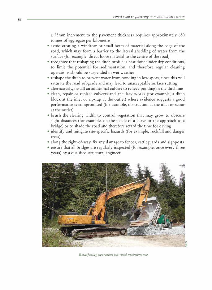
80Forest road engineering in mountainous terrain
a 75mm increment to the pavement thickness requires approximately 650 tonnes of aggregate per kilometre
• avoid creating a windrow or small berm of material along the edge of the road, which may form a barrier to the lateral shedding of water from the surface (for example, direct loose material to the centre of the road)
• recognize that reshaping the ditch profile is best done under dry conditions, to limit the potential for sedimentation, and therefore regular cleaning operations should be suspended in wet weather
• reshape the ditch to prevent water from ponding in low spots, since this will saturate the road subgrade and may lead to unacceptable surface rutting
• alternatively, install an additional culvert to relieve ponding in the ditchline • clean, repair or replace culverts and ancillary works (for example, a ditch
block at the inlet or rip-rap at the outlet) where evidence suggests a good performance is compromised (for example, obstruction at the inlet or scour at the outlet)
• brush the clearing width to control vegetation that may grow to obscure sight distances (for example, on the inside of a curve or the approach to a bridge) or to shade the road and therefore retard the time for drying
• identify and mitigate site-specific hazards (for example, rockfall and danger trees)
• along the right-of-way, fix any damage to fences, cattleguards and signposts • ensure that all bridges are regularly inspected (for example, once every three
years) by a qualified structural engineer
Resurfacing operation for road maintenance
FERIC

81Glossary
GLOSSARY
Aggregate Granular material used in road construction
Base course layerAggregate placed on top of the subgrade
Biotechnical stabilizationUse of vegetation to protect an exposed soil slope
Borrow pitLocation where soil or rock is extracted for use in construction
Cross-drainA drainage provision, for example a culvert, which moves water from one side of the road to the other
Geosynthetic A polymer fabric, for example a geotextile, used for soil stabilization
GabionWire mesh basket containing rock
Endhauling The removal and transport of excavated material to a stable waste area
FordA stream crossing that can be driven across at times of low streamflow
Full bench constructionA road that is built using no fill or sidecast
Riparian zoneThe area of land adjacent to streams, rivers, lakes and ponds
Rip-rap Large stone used to protect exposed soil from the erosive action of water

82Forest road engineering in mountainous terrain Map
SidecastExcavated material that is pushed or cast over the side of the road
SubgradeOn-site soil that is exposed during site preparation
Unstable slope Ground susceptible to mass movement or accelerated erosion as a result of surficial soils, bedrock lithology, groundwater and landform profile

83Appendix
APPENDIX
WORKSHOP PARTICIPANTS AND REVIEWERS
PARTICIPANTS AT THE EXPERT CONSULTATION ON PLANNING, DESIGN AND CONSTRUCTION OF FOREST ROADS Lampertheim, Germany
8-15 October 1998
Jurij Begus,Slovenian Forest Service, Ljubljana, SloveniaNikolaus Fernsebner,Forest Services of Lower Austria, St. PöltenRoger Hay,Consultant, Edinburgh, ScotlandHanns Höfle ,State Forest District, Bovenden, GermanyDirk Jaeger,University of Göttingen, Göttingen, GermanyJoachim Lorbach,FAO, Rome, ItalyDon Nearhood,Consultant, Portland, USAMadhuban Maskay,Lamjung/GTZ, Kathmandu, NepalEwald Pertlik ,University of Bodenkultur, Vienna, AustriaRobert Robek,Slovenian Forestry Institute, Ljubljana, SloveniaStanislav Sever,University of Zagreb, Zagreb, CroatiaKaren Ter-Ghazaryan,Forest Research Centre, Yerevan, ArmeniaKlaus Velbecker,Forest Workers Training Centre, Lampertheim, Germany

84Forest road engineering in mountainous terrain
REVIEWERS WHO PROVIDED WRITTEN COMMENTS ON THE DRAFT FAO GUIDE TO FOREST ROAD ENGINEERING IN MOUNTAINOUS TERRAIN
Doug Bennett, Forest Engineering Institute of British Columbia, Vancouver, Canada Don Dobson, Dobson Engineering, Kelowna, Canada Robert Douglas, University of Canterbury, Christchurch, New ZealandNikolaus Fernsebner,Forest Service of Lower Austria, Gaenserndorf, Austria,Hanns Höfle, Institute of Forest Technology and Forest Work Science, Göttingen, Germany Dirk Jaeger, University of New Brunswick, Fredericton, Canada Ron Jordens, Forest Road Engineering Services, Surrey, Canada Kevin Lyons, University of British Columbia, Vancouver, Canada Madhuban Maskay, Stupa Consultants, Kathmandu, Nepal

85Bibliography
BIBLIOGRAPHY
REFERENCES ON CODES OF FOREST PRACTICE AND SIMILAR GUIDELINES Australian Road Research Board. 2000. Unsealed roads manual: guidelines to good
practice (Ed. G. Giummara, revised edition). ARRB Transport Research Ltd., Vermont South, Victoria, Australia. 234p.
British Columbia Ministry of Forests. 2001. Forest Practices Code, Forest Road Engineering Guidebook, 2nd edition. Government of British Columbia, Victoria. 208p.
British Columbia Ministry of Forests. 1995. Forest Practices Code, Forest Development Plan Guidebook. Government of British Columbia, Victoria. 76p.
British Columbia Ministry of Forests. 1995. Forest Practices Code, Logging Plan Guidebook. Government of British Columbia, Victoria. 48p.
Douglas, R.A. 1999. Delivery, the transport of raw natural resource products from roadside to mill. University of Canterbury, School of Forestry, Christchurch, New Zealand. 202p.
Dykstra, D.P. and Heinrich, R. 1996. FAO Model code of forest harvesting practice. FAO, Rome, Italy. 85p.
Fannin, R.J. 2000. Basic geosynthetics: a guide to best practices. BiTech Publishers, Richmond, B.C., Canada. 86p.
FAO. 1977. Planning forest roads and harvesting systems. FAO Forestry Paper 2. FAO, Rome, Italy. 148p.
FAO. 1989. Watershed management field manual: road design and construction in sensitive watersheds. FAO Conservation Guide 13/5. FAO, Rome, Italy. 196p.
FAO. 1999. Code of Practice for Forest Harvesting in Asia-Pacific. RAP Publication:1999/12. FAO, Rome, Italy. 133p.
FAO. 2003. Code régional modèle d’exploitation forestière a faible impact dans les forêts denses tropicales humides. FAO, Rome, Italy. 123p.
Ferry, A.G. 1986. Unsealed roads: a manual of repair and maintenance for pavements. RRU Technical Recommendation TR/8. National Roads Board, Road Research Unit, Wellington, New Zealand. 150p.
Forestry Commission. 1993. Forest Practices Code. Hobart, Tasmania. 98p. Howell, J. 1999. Roadside bio-engineering: reference manual. H.M. Government of
Nepal, Department of Roads, Kathmandu, Nepal. 216p. ILO. 1981. Guide to tools and equipment for labour-based road construction.
International Labor Organisation, Geneva, Switzerland. 523p. Kantola, M. and Pertti H. 1988. Handbook on appropriate technology for forestry
operations in developing countries, Part II: Wood transport and road construction. Forestry Training Programme Publication 19, Helsinki, Finland. 190p.

86Forest road engineering in mountainous terrain
Larnier, M., Porcher, J.P., Travade, F. and Cosset, C. 1994. Passes a poissons: expertise, conception des ouvrages de franchissement. Collection Mise au Point, Conseil Superieur de la Peche, Paris, France. 336p.
LIRO. 1993. New Zealand Forest Code of Practice, 2nd edition. Logging Industry Research Organisation, Rotorua, New Zealand. 102p.
LIRO Forestry Solutions. 1999. Forest Roading Manual. Logging Industry Research Organisation, Rotorua, New Zealand. 404p.
Ontario Ministry of Natural Resources. 1995. Environmental guidelines for access roads and water crossings. Government of Ontario, Toronto. 64p.
Morris, J.M. 1990. Earth roads: a practical manual for the provision of access for agricultural and forestry projects in developing countries. Cranfield Press, Bedford, England.
Norwegian Ministry of Agriculture. 1997. Normaler for landbruksveier med byggebeskrivelse. Landsbrukdepartementet, Oslo, Norway. 60p.
Society of American Foresters. 1984. Forestry handbook, 2nd edition, Wenger, K.F. (ed.). Wiley, New York, USA. 1335p.
State Forestry Administration of China. 2001. National Code of Practice for Forest Harvesting in China (draft). 67p.
TRL. 1988. A guide to geometric design. Overseas Road Note 6. Transport Research Laboratory, Crowthorne, England. 29p.
TRL. 1997. Principles of low cost road engineering in mountainous regions. Overseas Road Note 16. Transport Research Laboratory, Crowthorne, England. 149p.
OTHER REFERENCES Arnold, G. 1996. Road design using GEOCOMP, SDR Map, ROADENG and
LUMBERJACK. LIRO Report, Vol.21, No.10, Logging Industry Research Organisation, Rotorua, New Zealand. 7p.
Acharya, B.N., Aryal, R., Karmacharya, B. and Meyer, W.P. 1999. Green roads in Nepal: best practices report. German Technical Cooperation and Swiss Agency for Development and Cooperation, Kathmandu, Nepal. 115p.
Aulerich, E. 1998. Better engineering and control of the construction of forest roads. Proceedings of the seminar on environmentally sound forest roads and wood transport, 17-22 June, 1996, Sinaia, Romania. FAO, Rome, Italy. pp.174-183.
Bennett, D.M. 1991. Application of new rock drilling technology to forest road construction in coastal British Columbia. Transportation Research Record, No.1291, Vol.2, Transportation Research Board, National Research Council, Washington, D.C., USA. pp. 217-224.
Bennett, D.M. 1999. Forest road construction in mountainous terrain: evaluating endhauling operations, Case Study No.1. FERIC Technical Note TN-290, Forest Engineering Research Institute of Canada, Vancouver, B.C., Canada. 10p.
Bennett, D.M. 2000. Forest road construction in mountainous terrain: evaluating endhauling operations, Case Study No.2. FERIC Advantage Vol.1, No.3, Forest Engineering Research Institute of Canada, Vancouver, B.C., Canada. 12p.

87Bibliography
Bolander, P. and Yamada, A. 1999. Dust palliative selection and application guide. United States Dept. of Agriculture, Forest Service, Project Report 9977 1207-SDTDC, San Dimas, California, USA. 20p.
Elias. 1998. Reduced impact timber harvesting in the tropical natural forest in Indonesia. Forest Harvesting Case-Study 11. FAO, Rome, Italy. 40p.
Fannin, R.J., Jordens, R.C. and Watson, D.R. 1997. The reinforced soil slope at Foley Creek, British Columbia. Proceedings, 11th Annual Vancouver Geotechnical Society Symposium, Vancouver, B.C., 30 May 1997. BiTech Publishers, Richmond, B.C., Canada. pp.51-60.
FAO. 1974. Logging and log transport in tropical high forest. FAO Forestry Development Paper No.18. FAO, Rome, Italy. 90p.
FAO. 1981. Planning of forest roads in mixed Dipterocarp forest of Sarawak. Working Paper No.3. FAO, Rome, Italy. 18p.
FAO. 1992. Cost control in forest harvesting and road construction. FAO Forestry Paper 99. FAO, Rome, Italy. 106p.
FAO/ATIBT. 1999. Road infrastructures in tropical forests: road to development or road to destruction? FAO, Rome. 64p.
Hamilton, P. 2000. The dirt on gravel: identifying soils you can use for road construction. FERIC Advantage, Vol.1, No.11. Forest Engineering Research Institute of Canada, Vancouver, B.C., Canada. 8p.
Hay, R. 1998. Forest road design. Proceedings of the seminar on environmentally sound forest roads and wood transport, 17-22 June, 1996, Sinaia, Romania. FAO, Rome, Italy. pp.44-49.
Heinrich, R. 1987. Special considerations on forest road construction in the tropics. Proceedings of FAO/Finland Training Course, Philippines, 23rd Nov. to 11th Dec., 1987. Finnida, Helsinki, Finland. pp.188-199.
Heinrich, R. 1998. Recent developments on environmentally friendly forest road construction and wood transport in mountainous forests. Proceedings of the seminar on environmentally sound forest roads and wood transport, 17-22 June, 1996, Sinaia, Romania. FAO, Rome, Italy. pp.366-376.
Johansen, D.K., Copstead, R. and Moll, J.M. 1997. Relief culverts. United States Dept. of Agriculture, Forest Service, Project Report 9777 1812-SDTDC, San Dimas, California, USA. 7p.
Northcote, T.G. and Hinch, S.G. 2004. Chapter 7: Fish migration and passage in forested watersheds. In, Fishes and forestry – worldwide watershed interactions and management (Eds. T.G. Northcote and G.F. Hartman), Blackwell Science, Oxford, U.K., pp.123-142.
Provencher, Y. 1995. Optimizing road maintenance intervals. Proceedings, 6th
International Conference on Low-Volume Roads, Minneapolis, Minnesota 25-29 June, 1995. National Academy Press, Washington, DC, USA. pp.199-207.
Rico Rodriguez, A., del Castillo, H. and Sowers, G.F. 1988. Soil mechanics in highway engineering. Trans Tech Publications, Claustal-Zellerfeld, Germany. 843p.
Sedlak, O. 1983. Forest road-net planning and wood harvesting. Report of the 4th FAO/Austria training course on mountain forest roads and harvesting, Ossiach, Austria, 30 May to 26 June, 1983. FAO Forestry Paper 14 Rev.1, FAO, Rome, Italy, pp.37-54.

88Forest road engineering in mountainous terrain
Sedlak, O.K. 1987. Introduction to mechanized forest road construction. Proceedings of FAO/Finland Training Course, Philippines, 23rd Nov. to 11th Dec., 1987. Finnida, Helsinki, Finland. pp.162-180.
Stjernberg, E. 1982. The use of hydraulic backhoes in forest road construction: central and eastern Canada. FERIC Special Report No.SR-20. Forest Engineering Research Institute of Canada, Vancouver, B.C., Canada. 60p.
Winkler, N. 1998. Environmentally sound road construction in mountainous terrain –applying advanced operating methods and tools. Forest Harvesting Case-Study 10. FAO, Rome. 54p.
Winkler, N. 1999. Environmentally sound forest infrastructure development and harvesting in Bhutan. Forest Harvesting Case-Study 12. FAO, Rome. 67p.