Embed Size (px)
Citation preview
Geocentric Datum of Australia
Technical Manual
Version 2.4ISBN 0-9579951-0-5
Intergovernmental Committee on Surveying and Mapping (ICSM)
Permanent Committee on Geodesy (PCG)
2 December 2014
Intergovernmental Committee on Surveying and Mapping
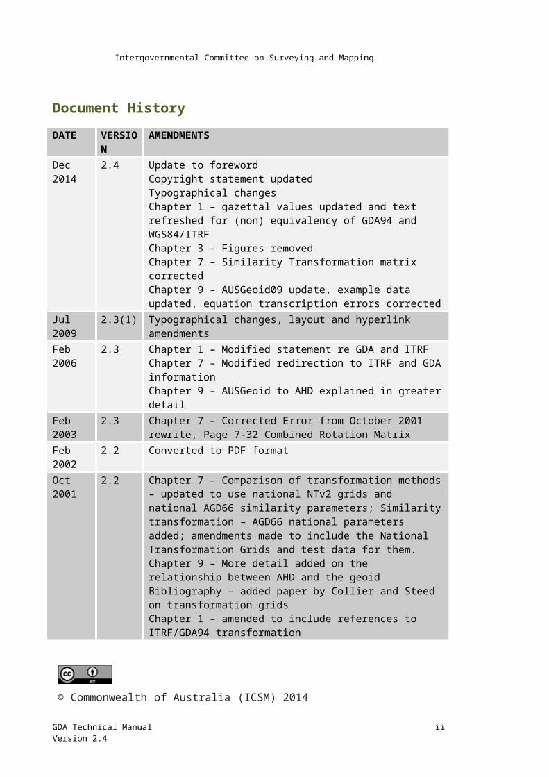
Document HistoryDATE VERSION AMENDMENTSDec 2014
2.4 Update to forewordCopyright statement updatedTypographical changesChapter 1 – gazettal values updated and text refreshed for (non) equivalency of GDA94 and WGS84/ITRFChapter 3 – Figures removedChapter 7 – Similarity Transformation matrix correctedChapter 9 – AUSGeoid09 update, example data updated, equation transcription errors corrected
Jul 2009 2.3(1) Typographical changes, layout and hyperlink amendmentsFeb 2006 2.3 Chapter 1 – Modified statement re GDA and ITRF
Chapter 7 – Modified redirection to ITRF and GDA informationChapter 9 – AUSGeoid to AHD explained in greater detail
Feb 2003 2.3 Chapter 7 – Corrected Error from October 2001 rewrite, Page 7-32 Combined Rotation Matrix
Feb 2002 2.2 Converted to PDF formatOct 2001 2.2 Chapter 7 – Comparison of transformation methods – updated to use
national NTv2 grids and national AGD66 similarity parameters; Similarity transformation – AGD66 national parameters added; amendments made to include the National Transformation Grids and test data for them.Chapter 9 – More detail added on the relationship between AHD and the geoidBibliography – added paper by Collier and Steed on transformation gridsChapter 1 – amended to include references to ITRF/GDA94 transformation
© Commonwealth of Australia (ICSM) 2014
With the exception of the ICSM logo and where otherwise noted, all material in this publication is provided under a Creative Commons Attribution 3.0 Australia Licence (h t t p : / /ww w .c r ea t i v ecommon s .o r g / licens e s / b y/3.0/au / )
GDA Technical Manual iiVersion 2.4
Intergovernmental Committee on Surveying and Mapping
Table of contentsDocument History........................................................................................................... ii
Table of contents........................................................................................................... iii
Figures...........................................................................................................................vi
Tables............................................................................................................................vi
Terms and Definitions...................................................................................................vii
Foreword........................................................................................................................1
Chapter 1 Background and Explanation......................................................................2
Background to GDA..........................................................................................................2
GDA Specifications............................................................................................................4
Terminology..................................................................................................................4
Definition......................................................................................................................4
GDA Extent.......................................................................................................................4
GDA and AGD...................................................................................................................5
GDA, ITRF and WGS84......................................................................................................6
Grid Coordinates..............................................................................................................6
Other Coordinates used in Australia................................................................................7
Australian Geodetic Datum (AGD)................................................................................7
World Geodetic System 1972 (WGS72)........................................................................8
NSWC-9Z2.....................................................................................................................8
"Clarke" Coordinates.....................................................................................................8
Chapter 2 Reduction of Measured Distances to the Ellipsoid.....................................10
Combined Formula.........................................................................................................10
Separate Formulae.........................................................................................................11
Heights in Distance Reduction........................................................................................11
Radius of Curvature........................................................................................................11
Chapter 3 Reduction of Measured Directions to the Ellipsoid....................................13
Formulae........................................................................................................................13
Sample Data...................................................................................................................14
Symbols..........................................................................................................................15
Chapter 4 Computations on the Ellipsoid..................................................................16
Vincenty's Inverse formulae...........................................................................................16
Vincenty's Direct formulae.............................................................................................17
Sample Data...................................................................................................................18
Symbols..........................................................................................................................18
Chapter 5 Conversion between Ellipsoidal and Grid Coordinates...............................19
GDA Technical Manual iiiVersion 2.4
Intergovernmental Committee on Surveying and Mapping
Preliminary Calculations.................................................................................................19
Geographical to Grid......................................................................................................20
Grid to Geographical......................................................................................................21
Sample Data...................................................................................................................22
Chapter 6 Grid Calculations......................................................................................23
Grid Bearing and Ellipsoidal Distance from MGA94 coordinates...................................23
MGA94 Coordinates from Grid bearing and Ellipsoidal Distance...................................24
Zone to Zone Transformations.......................................................................................25
Traverse Computation with Grid Coordinates, using Arc-to-Chord Corrections and Line Scale Factors..................................................................................................................25
Basic Outline...............................................................................................................26
Formulae and Symbols................................................................................................26
Sample Data...................................................................................................................27
Chapter 7 Transformation of Coordinates.................................................................28
High Accuracy Transformation (Grid Transformation)...................................................28
Interpolation software................................................................................................29
National Transformation Grids...................................................................................29
Medium Accuracy Transformation.................................................................................30
3-Dimensional Similarity Transformation...................................................................30
Conversion between Geographical and Cartesian Coordinates..................................33
Example using GDA94 (GRS80 ellipsoid).....................................................................33
Regional Transformation Parameters from AGD66 to GDA94....................................33
Low Accuracy Transformation........................................................................................35
Molodensky's Formulae..............................................................................................35
Transformation from AGD66 or AGD84 to GDA94.....................................................35
Examples.....................................................................................................................37
Simple Block Shift........................................................................................................38
Comparison of Transformation Methods.......................................................................38
Comparison of transformation by various methods...................................................38
Chapter 8 The Australian Height Datum (AHD)..........................................................42
Background.....................................................................................................................42
Basic and Supplementary Levelling................................................................................42
Tasmania........................................................................................................................42
Islands.............................................................................................................................42
AHD, Mean Sea Level and the Geoid..............................................................................42
Chapter 9 The Australian National Geoid..................................................................44
AUSGeoid09....................................................................................................................44
GDA Technical Manual ivVersion 2.4
Intergovernmental Committee on Surveying and Mapping
AUSGeoid09 Technical Specifications.............................................................................45
Chapter 10 Test Data..................................................................................................46
GDA94 and MGA94 (zone 55) values.............................................................................46
Traverse Diagram........................................................................................................47
Bibliography.................................................................................................................48
Diagrams......................................................................................................................50
Greek Alphabet.............................................................................................................52
GDA Technical Manual vVersion 2.4
Intergovernmental Committee on Surveying and Mapping
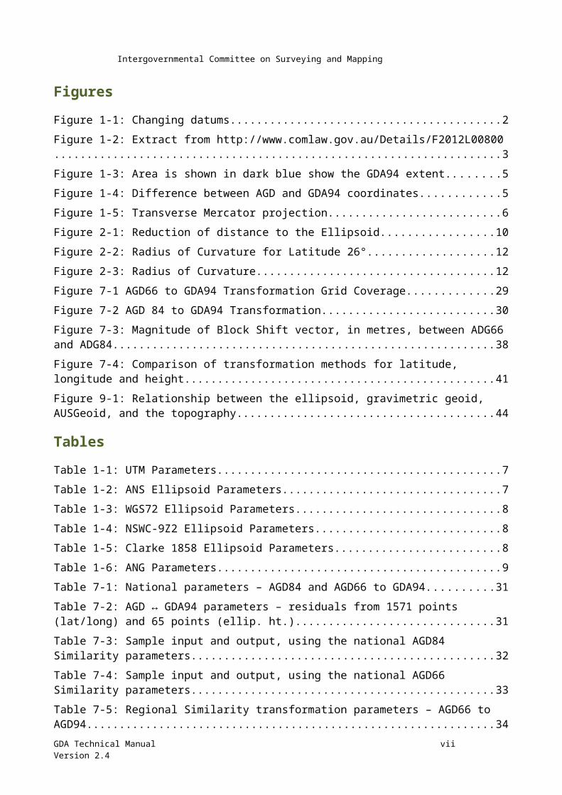
FiguresFigure 1-1: Changing datums.....................................................................................................................2
Figure 1-2: Extract from http://www.comlaw.gov.au/Details/F2012L00800............................................3
Figure 1-3: Area is shown in dark blue show the GDA94 extent................................................................5
Figure 1-4: Difference between AGD and GDA94 coordinates..................................................................5
Figure 1-5: Transverse Mercator projection..............................................................................................6
Figure 2-1: Reduction of distance to the Ellipsoid....................................................................................10
Figure 2-2: Radius of Curvature for Latitude 26°......................................................................................12
Figure 2-3: Radius of Curvature................................................................................................................12
Figure 7-1 AGD66 to GDA94 Transformation Grid Coverage...................................................................29
Figure 7-2 AGD 84 to GDA94 Transformation..........................................................................................30
Figure 7-3: Magnitude of Block Shift vector, in metres, between ADG66 and ADG84............................38
Figure 7-4: Comparison of transformation methods for latitude, longitude and height.........................41
Figure 9-1: Relationship between the ellipsoid, gravimetric geoid, AUSGeoid, and the topography......44
TablesTable 1-1: UTM Parameters.......................................................................................................................7
Table 1-2: ANS Ellipsoid Parameters..........................................................................................................7
Table 1-3: WGS72 Ellipsoid Parameters.....................................................................................................8
Table 1-4: NSWC-9Z2 Ellipsoid Parameters................................................................................................8
Table 1-5: Clarke 1858 Ellipsoid Parameters..............................................................................................8
Table 1-6: ANG Parameters........................................................................................................................9
Table 7-1: National parameters – AGD84 and AGD66 to GDA94.............................................................31
Table 7-2: AGD ↔ GDA94 parameters – residuals from 1571 points (lat/long) and 65 points (ellip. ht.)..................................................................................................................................................................31
Table 7-3: Sample input and output, using the national AGD84 Similarity parameters..........................32
Table 7-4: Sample input and output, using the national AGD66 Similarity parameters..........................33
Table 7-5: Regional Similarity transformation parameters – AGD66 to AGD94.......................................34
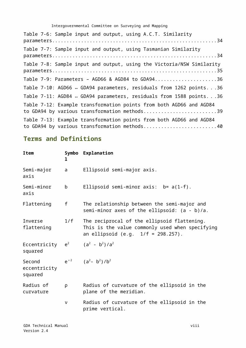
Table 7-6: Sample input and output, using A.C.T. Similarity parameters................................................34
Table 7-7: Sample input and output, using Tasmanian Similarity parameters........................................34
Table 7-8: Sample input and output, using the Victoria/NSW Similarity parameters..............................35
Table 7-9: Parameters – AGD66 & AGD84 to GDA94...............................................................................36
Table 7-10: AGD66 ↔ GDA94 parameters, residuals from 1262 points..................................................36
Table 7-11: AGD84 ↔ GDA94 parameters, residuals from 1588 points..................................................36
Table 7-12: Example transformation points from both AGD66 and AGD84 to GDA94 by various transformation methods..........................................................................................................................39
GDA Technical Manual viVersion 2.4
Intergovernmental Committee on Surveying and Mapping
Table 7-13: Example transformation points from both AGD66 and AGD84 to GDA94 by various transformation methods..........................................................................................................................40
Terms and Definitions
Item Symbol Explanation
Semi-major axis a Ellipsoid semi-major axis.
Semi-minor axis b Ellipsoid semi-minor axis: b= a(1-f).Flattening f The relationship between the semi-major and semi-minor axes of the
ellipsoid: (a - b)/a.Inverse flattening 1/f The reciprocal of the ellipsoid flattening. This is the value commonly
used when specifying an ellipsoid (e.g. 1/f = 298.257).
Eccentricity squared
e2 (a2 - b2)/a2
Second eccentricity squared
e'2 (a2- b2)/b2
Radius of curvature
ρ Radius of curvature of the ellipsoid in the plane of the meridian.
ν Radius of curvature of the ellipsoid in the prime vertical.
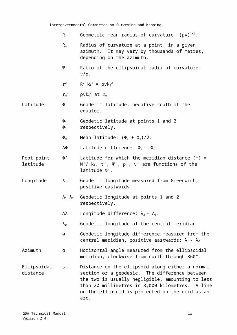
R Geometric mean radius of curvature: (ρν)1/2.Rα Radius of curvature at a point, in a given azimuth. It may vary by thousands of metres, depending on the azimuth.
Ψ Ratio of the ellipsoidal radii of curvature: ν/ρ.r2 R2 k02 = ρνk02rm2 ρνk02 at Φm
Latitude Φ Geodetic latitude, negative south of the equator.Φ1, Φ2Geodetic latitude at points 1 and 2 respectively.
Φm Mean latitude: (Φ1 + Φ2)/2.∆Φ Latitude difference: Φ2 - Φ1.Foot point latitude Φ’ Latitude for which the meridian distance (m) = N'/ k0. t’, Ψ’, ρ’, ν’
are functions of the latitude Φ’.GDA Technical Manual viiVersion 2.4
Intergovernmental Committee on Surveying and Mapping
Longitude λ Geodetic longitude measured from Greenwich, positive eastwards.
Λ1,λ2 Geodetic longitude at points 1 and 2 respectively.∆λ Longitude difference: λ2 - Λ1.λ0 Geodetic longitude of the central meridian.ω Geodetic longitude difference measured from the central meridian, positive eastwards: λ - λ0.
Azimuth α Horizontal angle measured from the ellipsoidal meridian, clockwise from north through 360°.
Ellipsoidal distance s Distance on the ellipsoid along either a normal section or a geodesic. The difference between the two is usually negligible, amounting to less than 20 millimetres in 3,000 kilometres. A line on the ellipsoid is projected on the grid as an arc.
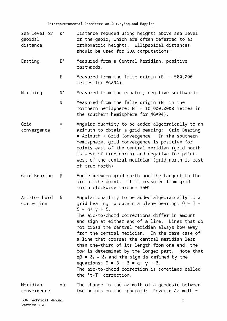
Sea level or geoidal distance
s' Distance reduced using heights above sea level or the geoid, which are often referred to as orthometric heights. Ellipsoidal distances should be used for GDA computations.
Easting E’ Measured from a Central Meridian, positive eastwards.
E Measured from the false origin (E' + 500,000 metres for MGA94).
Northing N’ Measured from the equator, negative southwards.N Measured from the false origin (N' in the northern hemisphere; N' + 10,000,0000 metres in the southern hemisphere for MGA94).
Grid convergence γ Angular quantity to be added algebraically to an azimuth to obtain a grid bearing: Grid Bearing = Azimuth + Grid Convergence. In the southern hemisphere, grid convergence is positive for points east of the central meridian (grid north is west of true north) and negative for points west of the central meridian (grid north is east of true north).
Grid Bearing β Angle between grid north and the tangent to the arc at the point. It is measured from grid north clockwise through 360°.
Arc-to-chord Correction
δ Angular quantity to be added algebraically to a grid bearing to obtain a plane bearing: θ = β + δ = α+ γ + δ.The arc-to-chord corrections differ in amount and sign at either end of a line. Lines that do not cross the central meridian always bow away from the central meridian. In the rare case of a line that crosses the central meridian less than one-third of its length from one end, the bow is determined by the longer part. Note that ∆β = δ1 - δ2 and the sign is defined by the equations: θ = β + δ = α+ γ + δ.
GDA Technical Manual viiiVersion 2.4
Intergovernmental Committee on Surveying and Mapping
The arc-to-chord correction is sometimes called the 't-T' correction.
Meridian convergence
∆α The change in the azimuth of a geodesic between two points on the spheroid: Reverse Azimuth = Forward Azimuth + Meridian Convergence ± 180°: α 21 = α12 + ∆α± 180°.
Line curvature ∆β The change in grid bearing between two points on the arc. Reverse grid bearing = Forward grid bearing + Line curvature ± 180°: β2 = β1 + ∆β ± 180°.
Plane bearing θ The angle between grid north and the straight line on the grid between the ends of the arc formed by the projection of the ellipsoidal distance; measured clockwise through 360°.
Grid distance S The length measured on the grid, along the arc of the projected ellipsoid distance.
Plane distance L The length of the straight line on the grid between the ends of the arc of the projected ellipsoidal distance. The difference in length between the plane distance (L) and the grid distance (S) is nearly always negligible. Using plane bearings and plane distances, the formulae of plane trigonometry hold rigorously: tanθ=ΔE / ΔN , ΔE=L sin θ, ΔN=L cosθ.
Meridian distance m True distance from the equator, along the meridian, negative southwards.G Mean length of an arc of one degree of the meridian.σ Meridian distance expressed as units G: σ = m/G.
Central scale factor k0 Scale factor on the central meridian (0.9996 for MGA94).
Point scale factor k Ratio of an infinitesimal distance at a point on the grid to the corresponding distance on the spheroid: k = dL/ds = dS/ds It is the distinguishing feature of conformal projections, such as the Universal Transverse Mercator used for MGA94, that this ratio is independent of the azimuth of the infinitesimal distance.
Line scale factor K Ratio of a plane distance (L) to the corresponding ellipsoidal distance (s): K = L/s ≈ S/s. The point scale factor will in general vary from point to point along a line on the grid.
Ellipsoidal height h Ellipsoidal Height (h) is the distance of a point above the ellipsoid, measured along the normal from that point to the surface of the ellipsoid used.
GDA Technical Manual ixVersion 2.4
Intergovernmental Committee on Surveying and Mapping
∆h Change in ellipsoidal height (m).
Height above the geoid
H Height of a point above the geoid measured along the normal from that point to the surface of the geoid. It is also referred to as the orthometric height.HAHD The derived difference in height, from AUSGeoid09, between AHD and the surface.
Geoid-ellipsoid separation
N Distance from the surface of the ellipsoid used, to the surface of the geoid measured along the normal to this ellipsoid. This separation is positive if the geoid is above the ellipsoid and negative if the geoid is below the ellipsoid: h - H = geoid ellipsoid separation.
NAHD The distance between the ellipsoid and AUSGeoid09 measured along the normal to this ellipsoid.
Earth-centred Cartesian coordinates.
X, Y, Z A three dimensional coordinate system which has its origin at (or near) the centre of the earth. These coordinates are commonly used for satellite derived positions (e.g. GNSS) and although they relate to a specific reference system they are independent of any ellipsoid. The positive Z axis coincides with (or is parallel to) the earth’s mean axis of rotation and the X and Y axes are chosen to obtain a right-handed coordinate system; for convenience it can be assumed that the positive arm of the X axis passes through the Greenwich meridian.
Transformation parameters
∆a Change in ellipsoid semi-major axis (e.g. from ANS to GRS80) (m).
∆f change in ellipsoid flattening (e.g. from ANS to GRS80).
∆X origin shift along the X axis (m).∆Y origin shift along the Y axis (m).∆Z origin shift along the Z axis (m).Rx Rotation of the X axis (radians); positive when anti-clockwise as viewed from the positive end of the axis looking towards the origin.
Ry Rotation of the Y axis (radians); positive when anti-clockwise as viewed from the positive end of the axis looking towards the origin.
Rz Rotation of the Z axis (radians); positive when anti-clockwise as viewed from the positive end of the axis looking towards the origin.
GDA Technical Manual xVersion 2.4
Intergovernmental Committee on Surveying and Mapping
Sc Change in scale (parts per million – ppm).
GDA Technical Manual xiVersion 2.4
Intergovernmental Committee on Surveying and Mapping
ForewordThe Geocentric Datum of Australia Technical Manual is principally designed to explain all facets of the Geocentric Datum of Australia, and continues the tradition of providing complete formulae and worked examples.
To cater for the enormous changes that have taken place since the Australian Geodetic Datum Technical Manual was originally published, the chapters on the geoid and coordinate transformation have been expanded. A brief history of Australian coordinates has also been included.
The coordinates of the Australian Fiducial Network (AFN) geodetic stations have been updated to reflect the 2012 gazettal of 21 geodetic stations, strengthening and densifying Australia’s recognized-value standard for position.
GDA Technical ManualVersion 2.4 1
Intergovernmental Committee on Surveying and Mapping
Chapter 1 Background and ExplanationThe Geocentric Datum of Australia (GDA) is the Australian coordinate system, replacing the Australian Geodetic Datum (AGD). GDA is part of a Global Geodetic Reference Frame (GGRF) and is directly compatible with Global Navigation Satellite Systems (GNSS) such as the Global Positioning System (GPS), GLObal NAvigation Satellite System (GLONASS), BeiDou, and Galileo, as well as Regional Navigation Satellite Systems (RNSS), such as the Indian Regional Navigational Satellite System (IRNSS) and Quasi-Zenith Satellite System (QZSS). It is the responsibility of the Intergovernmental Committee on Surveying and Mapping (ICSM) to maintain GDA.
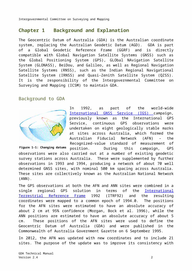
Background to GDA In 1992, as part of the world-wide International GNSS Service (IGS) campaign, previously known as the International GPS Service, continuous GPS observations were undertaken on eight geologically stable marks at sites across Australia, which formed the Australian Fiducial Network (AFN) – the Recognized-value standard of measurement of position. During this campaign, GPS observations were also carried out at a number of existing geodetic survey stations across Australia. These were supplemented by further observations in 1993 and 1994, producing a network of about 70 well determined GNSS sites, with nominal 500 km spacing across
Australia. These sites are collectively known as the Australian National Network (ANN).
The GPS observations at both the AFN and ANN sites were combined in a single regional GPS solution in terms of the International Terrestrial Reference Frame 1992 (ITRF92) and the resulting coordinates were mapped to a common epoch of 1994.0. The positions for the AFN sites were estimated to have an absolute accuracy of about 2 cm at 95% confidence (Morgan, Bock et al. 1996), while the ANN positions are estimated to have an absolute accuracy of about 5 cm. These positions of the AFN sites were used to define the Geocentric Datum of Australia (GDA) and were published in the Commonwealth of Australia Government Gazette on 6 September 1995.
In 2012, the AFN was updated with new coordinates and to include 21 sites. The purpose of the update was to improve its consistency with the most recent realisation of the International Terrestrial Reference Frame. The updated AFN coordinates have been adopted from ITRF2008 and subsequently transformed to GDA94 (i.e. ITRF1992 at epoch 1994.0) using the Dawson-Woods transformation parameters (2010). For those stations with multiple coordinate estimates in ITRF 2008 the most recent coordinate estimate has been adopted.
The new Gazettal values are in shown in the Commonwealth of Australia Gazette extract below.
GDA Technical ManualVersion 2.4 2
Figure 1-1: Changing datums
Intergovernmental Committee on Surveying and Mapping
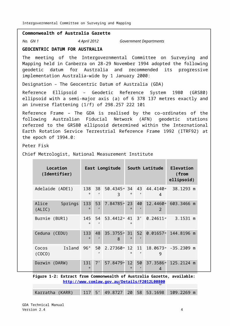
Commonwealth of Australia GazetteNo. GN 1 4 April 2012 Government Departments
GEOCENTRIC DATUM FOR AUSTRALIA
The meeting of the Intergovernmental Committee on Surveying and Mapping held in Canberra on 28-29 November 1994 adopted the following geodetic datum for Australia and recommended its progressive implementation Australia-wide by 1 January 2000:
Designation – The Geocentric Datum of Australia (GDA)
Reference Ellipsoid – Geodetic Reference System 1980 (GRS80) ellipsoid with a semi-major axis (a) of 6 378 137 metres exactly and an inverse flattening (1/f) of 298.257 222 101
Reference Frame – The GDA is realised by the co-ordinates of the following Australian Fiducial Network (AFN) geodetic stations referred to the GRS80 ellipsoid determined within the International Earth Rotation Service Terrestrial Reference Frame 1992 (ITRF92) at the epoch of 1994.0:
Peter Fisk
Chief Metrologist, National Measurement Institute
Location (Identifier) East Longitude South Latitude Elevation(from ellipsoid)
Adelaide (ADE1) 138° 38’ 50.43453” 34° 43’ 44.41404” 38.1293 m
Alice Springs (ALIC) 133° 53’ 7.84785” 23° 40’ 12.44602” 603.3466 m
Burnie (BUR1) 145° 54’ 53.4412” 41° 3’ 0.24611” 3.1531 m
Ceduna (CEDU) 133° 48’ 35.37558” 31° 52’ 0.01657” 144.8196 m
Cocos Island (COCO) 96° 50’ 2.27360” 12° 11’ 18.06739” -35.2309 m
Darwin (DARW) 131° 7’ 57.8479” 12° 50’ 37.35864” 125.2124 m
Hobart (HOB2) 147° 26’ 19.43574” 42° 48’ 16.98538” 41.1389 m
Karratha (KARR) 117° 5’ 49.87277” 20° 58’ 53.16983” 109.2269 m
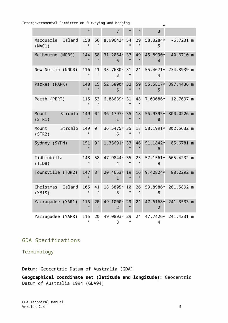
Macquarie Island (MAC1) 158° 56’ 8.99643” 54° 29’ 58.32845” -6.7231 m
Melbourne (MOBS) 144° 58’ 31.20646” 37° 49’ 45.89904” 40.6710 m
New Norcia (NNOR) 116° 11’ 33.76803” 31° 2’ 55.46714” 234.8939 m
Parkes (PARK) 148° 15’ 52.58905” 32° 59’ 55.58175” 397.4436 m
Perth (PERT) 115° 53’ 6.88639” 31° 48’ 7.09686” 12.7697 m
Mount Stromlo (STR1) 149° 0’ 36.17971” 35° 18’ 55.93958” 800.0226 m
Mount Stromlo (STR2) 149° 0’ 36.54756” 35° 18’ 58.1991” 802.5632 m
Sydney (SYDN) 151° 9’ 1.35691” 33° 46’ 51.18426” 85.6781 m
Tidbinbilla (TIDB) 148° 58’ 47.98444” 35° 23’ 57.15619” 665.4232 m
Townsville (TOW2) 147° 3’ 20.46531” 19° 16’ 9.42824” 88.2292 m
GDA Technical ManualVersion 2.4 3
Figure 1-2: Extract from Commonwealth of Australia Gazette, available: http://www.comlaw.gov.au/Details/F2012L00800
Intergovernmental Committee on Surveying and Mapping
Christmas Island (XMIS) 105° 41’ 18.58058” 10° 26’ 59.89868” 261.5892 m
Yarragadee (YAR1) 115° 20’ 49.10002” 29° 2’ 47.61682” 241.3533 m
Yarragadee (YARR) 115° 20’ 49.08938” 29° 2’ 47.74264” 241.4231 m
GDA Specifications Terminology
Datum: Geocentric Datum of Australia (GDA)
Geographical coordinate set (latitude and longitude): Geocentric Datum of Australia 1994 (GDA94)
Grid coordinates (Universal Transverse Mercator, using the GRS80 ellipsoid): Map Grid of Australia 1994 (MGA94)
Definition Reference Frame ITRF92 (International Terrestrial Reference Frame 1992)
Epoch 1994.0
Ellipsoid GRS80
Semi-major axis (a) 6,378,137.0 m
Inverse flattening (1/f) 298.257222101
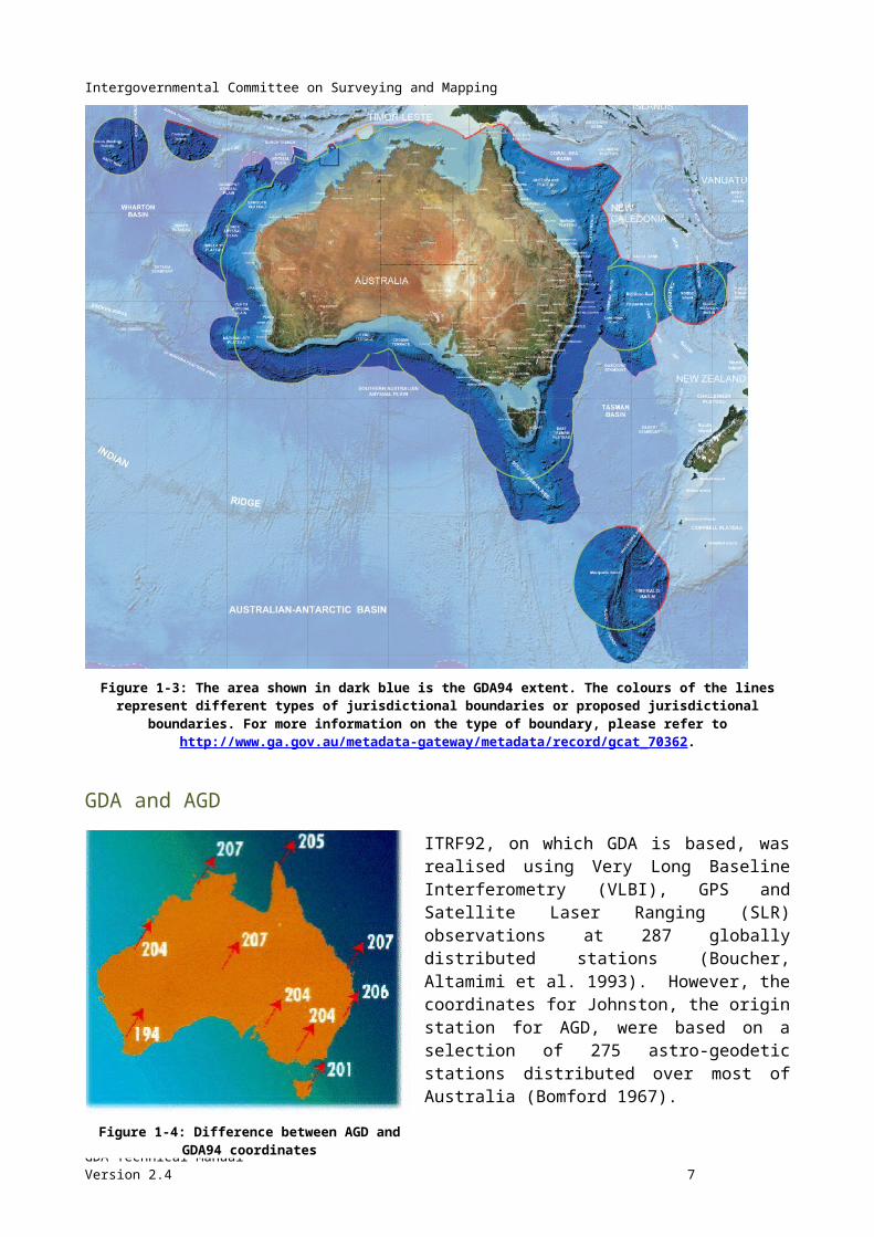
GDA ExtentIncludes all the areas contained within Australia’s marine jurisdiction within 200 nautical miles of Australia and its external territories, and the areas of Australia’s continental shelf beyond 200 nautical miles as confirmed by the United Nations Commission on the Limits of the Continental Shelf. The areas include Cocos (Keeling) Island, Christmas Island, Norfolk Island and Macquarie Island but excludes Heard-McDonald Island and the Australian Antarctic Territory (AAT) as shown in Figure 1-3.
GDA Technical ManualVersion 2.4 4
Intergovernmental Committee on Surveying and Mapping
Figure 1-3: The area shown in dark blue is the GDA94 extent. The colours of the lines represent different types of jurisdictional boundaries or proposed jurisdictional boundaries. For more information on the type of boundary, please refer to
http://www.ga.gov.au/metadata-gateway/metadata/record/gcat_70362.
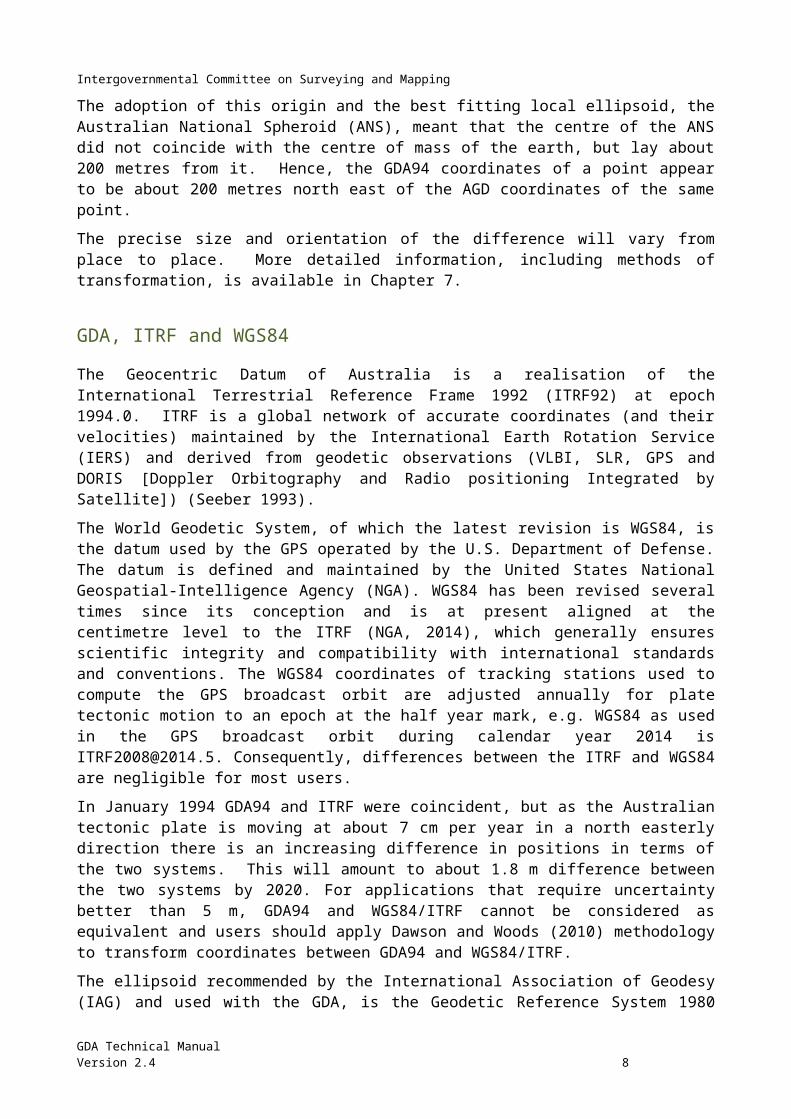
GDA and AGD ITRF92, on which GDA is based, was realised using Very Long Baseline Interferometry (VLBI), GPS and Satellite Laser Ranging (SLR) observations at 287 globally distributed stations (Boucher, Altamimi et al. 1993). However, the coordinates for Johnston, the origin station for AGD, were based on a selection of 275 astro-geodetic stations distributed over most of Australia (Bomford 1967).
The adoption of this origin and the best fitting local ellipsoid, the Australian National Spheroid (ANS), meant that the centre of the ANS did not coincide with the centre of mass of the earth, but lay about 200 metres from it. Hence, the GDA94 coordinates of a point appear to be about 200 metres north east of the AGD coordinates of the same point.
GDA Technical ManualVersion 2.4 5
Figure 1-4: Difference between AGD and GDA94 coordinates
Intergovernmental Committee on Surveying and Mapping
The precise size and orientation of the difference will vary from place to place. More detailed information, including methods of transformation, is available in Chapter 7.
GDA, ITRF and WGS84 The Geocentric Datum of Australia is a realisation of the International Terrestrial Reference Frame 1992 (ITRF92) at epoch 1994.0. ITRF is a global network of accurate coordinates (and their velocities) maintained by the International Earth Rotation Service (IERS) and derived from geodetic observations (VLBI, SLR, GPS and DORIS [Doppler Orbitography and Radio positioning Integrated by Satellite]) (Seeber 1993).
The World Geodetic System, of which the latest revision is WGS84, is the datum used by the GPS operated by the U.S. Department of Defense. The datum is defined and maintained by the United States National Geospatial-Intelligence Agency (NGA). WGS84 has been revised several times since its conception and is at present aligned at the centimetre level to the ITRF (NGA, 2014), which generally ensures scientific integrity and compatibility with international standards and conventions. The WGS84 coordinates of tracking stations used to compute the GPS broadcast orbit are adjusted annually for plate tectonic motion to an epoch at the half year mark, e.g. WGS84 as used in the GPS broadcast orbit during calendar year 2014 is [email protected]. Consequently, differences between the ITRF and WGS84 are negligible for most users.
In January 1994 GDA94 and ITRF were coincident, but as the Australian tectonic plate is moving at about 7 cm per year in a north easterly direction there is an increasing difference in positions in terms of the two systems. This will amount to about 1.8 m difference between the two systems by 2020. For applications that require uncertainty better than 5 m, GDA94 and WGS84/ITRF cannot be considered as equivalent and users should apply Dawson and Woods (2010) methodology to transform coordinates between GDA94 and WGS84/ITRF.
The ellipsoid recommended by the International Association of Geodesy (IAG) and used with the GDA, is the Geodetic Reference System 1980 ellipsoid. The parameters of the WGS84 ellipsoid "... are identical to those for the GRS80 ellipsoid with one minor exception. The coefficient form used for the second degree zonal is that of the WGS84 Earth Gravitational Model rather than the notation J2 used with GRS80." (DMA 1987). Consequently, “the GRS80 and WGS84 ellipsoids have a very small difference in the inverse flattening, but this difference is insignificant for most practical applications”.
Ellipsoid GRS80 WGS84
Semi major axis (a) 6,378,137.0 6,378,137.0
Inverse flattening (1/f) 298.257222101 298.257223563
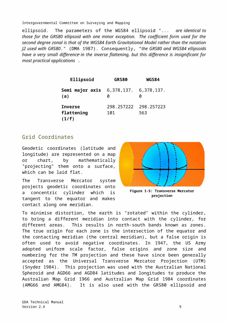
Grid Coordinates Geodetic coordinates (latitude and longitude) are represented on a map or chart, by mathematically "projecting" them onto a surface, which can be laid flat.
GDA Technical ManualVersion 2.4 6
Figure 1-5: Transverse Mercator projection
Intergovernmental Committee on Surveying and Mapping
The Transverse Mercator system projects geodetic coordinates onto a concentric cylinder which is tangent to the equator and makes contact along one meridian.
To minimise distortion, the earth is "rotated" within the cylinder, to bring a different meridian into contact with the cylinder, for different areas. This results in north-south bands known as zones. The true origin for each zone is the intersection of the equator and the contacting meridian (the central meridian), but a false origin is often used to avoid negative coordinates. In 1947, the US Army adopted uniform scale factor, false origins and zone size and numbering for the TM projection and these have since been generally accepted as the Universal Transverse Mercator Projection (UTM) (Snyder 1984). This projection was used with the Australian National Spheroid and AGD66 and AGD84 latitudes and longitudes to produce the Australian Map Grid 1966 and Australian Map Grid 1984 coordinates (AMG66 and AMG84). It is also used with the GRS80 ellipsoid and GDA94 latitudes and longitudes to produce Map Grid of Australia 1994 coordinates (MGA94).
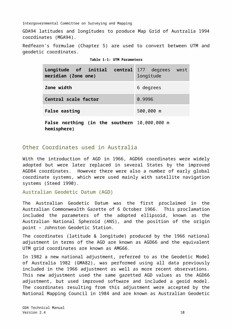
Redfearn's formulae (Chapter 5) are used to convert between UTM and geodetic coordinates. Table 1-1: UTM Parameters
Longitude of initial central meridian (Zone one) 177 degrees west longitude
Zone width 6 degrees
Central scale factor 0.9996
False easting 500,000 m
False northing (in the southern hemisphere) 10,000,000 m
Other Coordinates used in Australia With the introduction of AGD in 1966, AGD66 coordinates were widely adopted but were later replaced in several States by the improved AGD84 coordinates. However there were also a number of early global coordinate systems, which were used mainly with satellite navigation systems (Steed 1990).
Australian Geodetic Datum (AGD) The Australian Geodetic Datum was the first proclaimed in the Australian Commonwealth Gazette of 6 October 1966. This proclamation included the parameters of the adopted ellipsoid, known as the Australian National Spheroid (ANS), and the position of the origin point – Johnston Geodetic Station.
The coordinates (latitude & longitude) produced by the 1966 national adjustment in terms of the AGD are known as AGD66 and the equivalent UTM grid coordinates are known as AMG66.
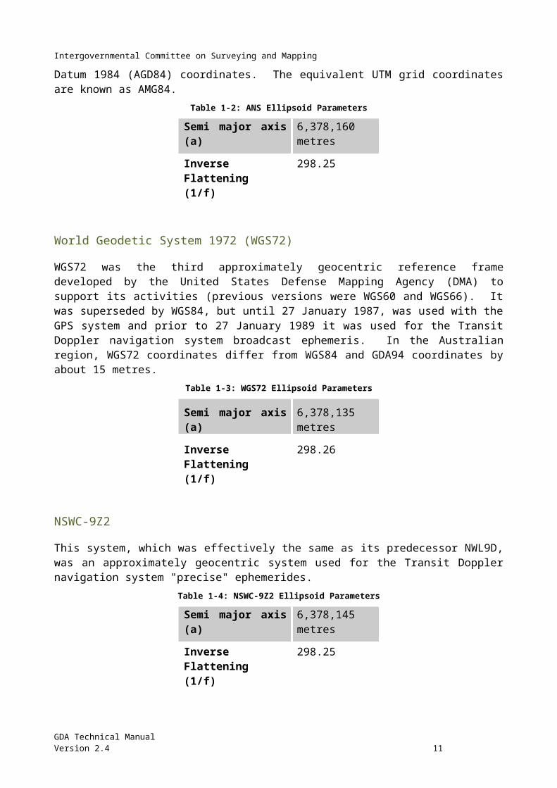
In 1982 a new national adjustment, referred to as the Geodetic Model of Australia 1982 (GMA82), was performed using all data previously included in the 1966 adjustment as well as more recent observations. This new adjustment used the same gazetted AGD values as the AGD66 adjustment, but used improved software and included a geoid model. The coordinates resulting from this adjustment were accepted by the National Mapping Council in 1984 and are known as Australian Geodetic Datum 1984 (AGD84) coordinates. The equivalent UTM grid coordinates are known as AMG84.
GDA Technical ManualVersion 2.4 7
Intergovernmental Committee on Surveying and Mapping
Table 1-2: ANS Ellipsoid Parameters
Semi major axis (a) 6,378,160 metres
Inverse Flattening (1/f) 298.25
World Geodetic System 1972 (WGS72)WGS72 was the third approximately geocentric reference frame developed by the United States Defense Mapping Agency (DMA) to support its activities (previous versions were WGS60 and WGS66). It was superseded by WGS84, but until 27 January 1987, was used with the GPS system and prior to 27 January 1989 it was used for the Transit Doppler navigation system broadcast ephemeris. In the Australian region, WGS72 coordinates differ from WGS84 and GDA94 coordinates by about 15 metres.
Table 1-3: WGS72 Ellipsoid Parameters
Semi major axis (a) 6,378,135 metres
Inverse Flattening (1/f) 298.26
NSWC-9Z2 This system, which was effectively the same as its predecessor NWL9D, was an approximately geocentric system used for the Transit Doppler navigation system "precise" ephemerides.
Table 1-4: NSWC-9Z2 Ellipsoid Parameters
Semi major axis (a) 6,378,145 metres
Inverse Flattening (1/f) 298.25
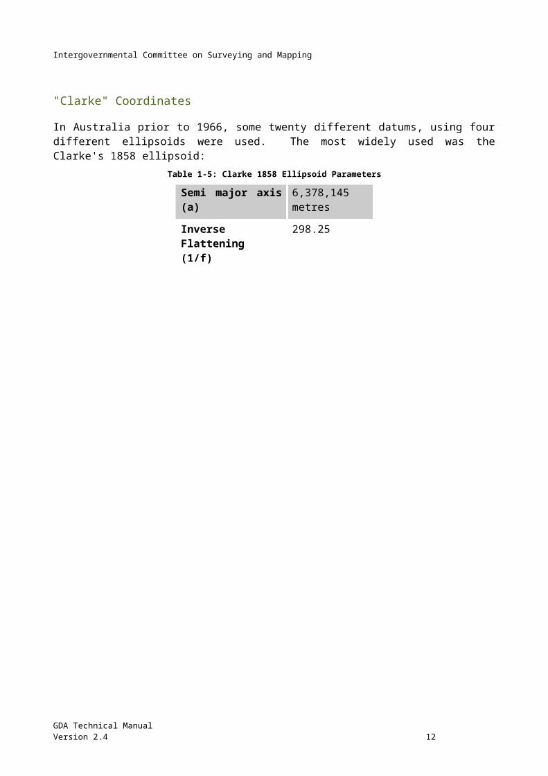
"Clarke" Coordinates In Australia prior to 1966, some twenty different datums, using four different ellipsoids were used. The most widely used was the Clarke's 1858 ellipsoid:
Table 1-5: Clarke 1858 Ellipsoid Parameters
Semi major axis (a) 6,378,145 metres
Inverse Flattening (1/f) 298.25
GDA Technical ManualVersion 2.4 8
Intergovernmental Committee on Surveying and Mapping
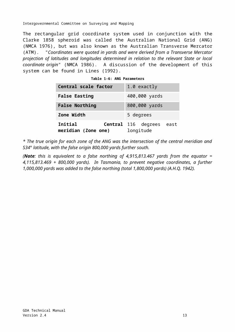
The rectangular grid coordinate system used in conjunction with the Clarke 1858 spheroid was called the Australian National Grid (ANG) (NMCA 1976), but was also known as the Australian Transverse Mercator (ATM). "Coordinates were quoted in yards and were derived from a Transverse Mercator projection of latitudes and longitudes determined in relation to the relevant State or local coordinate origin" (NMCA 1986). A discussion of the development of this system can be found in Lines (1992).
Table 1-6: ANG Parameters
Central scale factor 1.0 exactly
False Easting 400,000 yards
False Northing 800,000 yards
Zone Width 5 degrees
Initial Central meridian (Zone one)
116 degrees east longitude
* The true origin for each zone of the ANG was the intersection of the central meridian and S34° latitude, with the false origin 800,000 yards further south.
(Note: this is equivalent to a false northing of 4,915,813.467 yards from the equator = 4,115,813.469 + 800,000 yards). In Tasmania, to prevent negative coordinates, a further 1,000,000 yards was added to the false northing (total 1,800,000 yards) (A.H.Q. 1942).
GDA Technical ManualVersion 2.4 9
Intergovernmental Committee on Surveying and Mapping
Chapter 2 Reduction of Measured Distances to the Ellipsoid
Excel Spreadsheet – Calculation of Reduced Distance
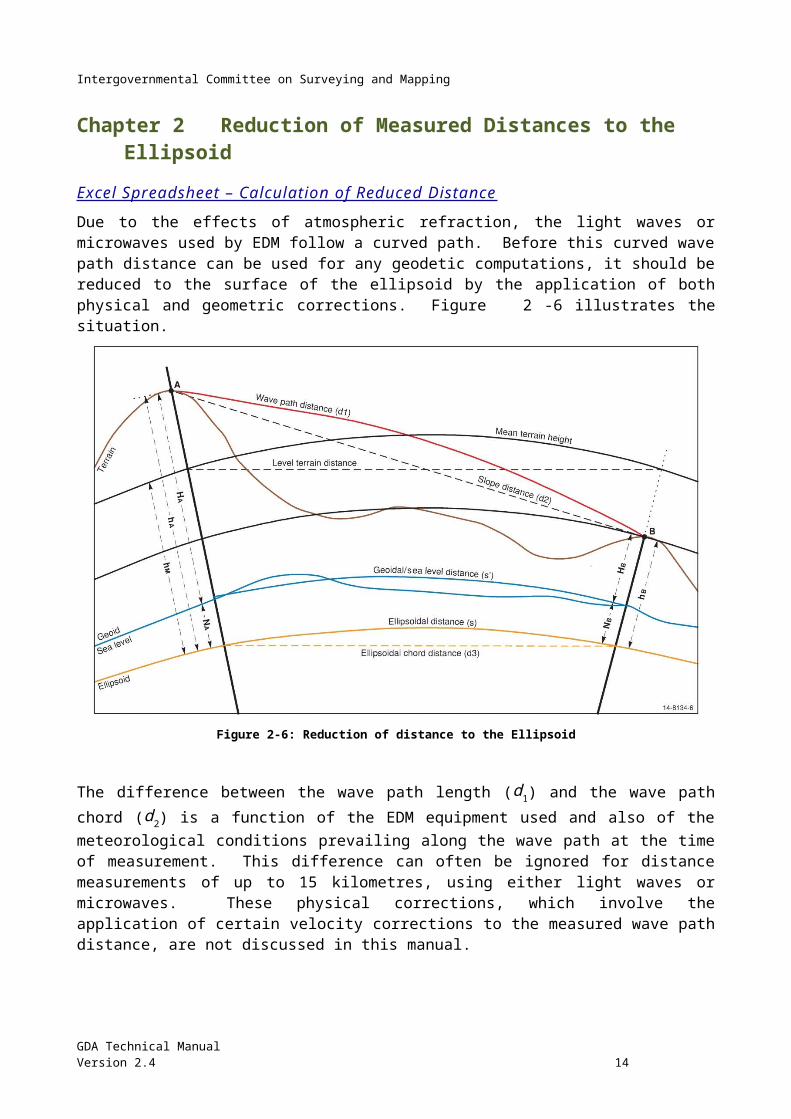
Due to the effects of atmospheric refraction, the light waves or microwaves used by EDM follow a curved path. Before this curved wave path distance can be used for any geodetic computations, it should be reduced to the surface of the ellipsoid by the application of both physical and geometric corrections. Figure 2-6 illustrates the situation.
Figure 2-6: Reduction of distance to the Ellipsoid
The difference between the wave path length (d1) and the wave path chord (d2) is a function of the EDM equipment used and also of the meteorological conditions prevailing along the wave path at the time of measurement. This difference can often be ignored for distance measurements of up to 15 kilometres, using either light waves or microwaves. These physical corrections, which involve the application of certain velocity corrections to the measured wave path distance, are not discussed in this manual.
Combined Formula The reduction of the wave path chord distance (d2), to the ellipsoidal chord distance (d3), can be given as a single rigorous formula (Clark 1966):
d3=[ (d22−(hA−hB )2 )/ (1+h A/ Rα ) (1+hB /Rα )]1 /2
The ellipsoidal chord distance (d3) is then easily reduced to the ellipsoidal distance:
GDA Technical ManualVersion 2.4 10
Intergovernmental Committee on Surveying and Mapping
s=d3 [1+(d32/24 Rα
2+3d34/640 Rα
4+...) ]where Rα is the radius of curvature in the azimuth of the line.
For a distance of 30 kilometres in the Australian region the chord-to-arc correction is 0.028 m. For a distance of 50 km, the correction reaches about 0.13 m and it is more than 1 m at 100 km. The second term in the chord-to-arc correction is less than 1 mm for lines up to 100 km, anywhere in Australia and usually can be ignored.
Separate Formulae The combined formula above includes the slope and ellipsoid level corrections. The slope correction reduces the wave path chord (d2) to a horizontal distance at the mean elevation of the terminals of the line and the ellipsoid level correction reduces the horizontal distance to the ellipsoid chord distance (d3). The chord-to-arc correction is then applied to the ellipsoid chord distance, as with the combined formula, to give the ellipsoidal distance (s).
Slopecorrection=(d22−Δh2 )1 /2
−d2
Ellipsoidal correction=(hm /Rα) (d22−Δh2 )1/2
Chord ¿arc correction=+d33 /24 Rα
2 {+3 d35 /640 Rα
4+... }
Heights in Distance Reduction The formulae given in this chapter use ellipsoidal heights (h). If the geoid-ellipsoid separation (Chapter 9 – N value) is ignored and only the height above the geoid (H – the orthometric or AHD height) is used, an error of one part per million (ppm) will be introduced for every 6.5 m of N value (plus any error due to the change in N value along the line). As the N value in terms of GDA varies from -35 m in southwest Australia, to about 70 m in northern Queensland, errors from -5 to almost 11 ppm could be expected. Of course there are areas where the N value is small and the error would also be small.
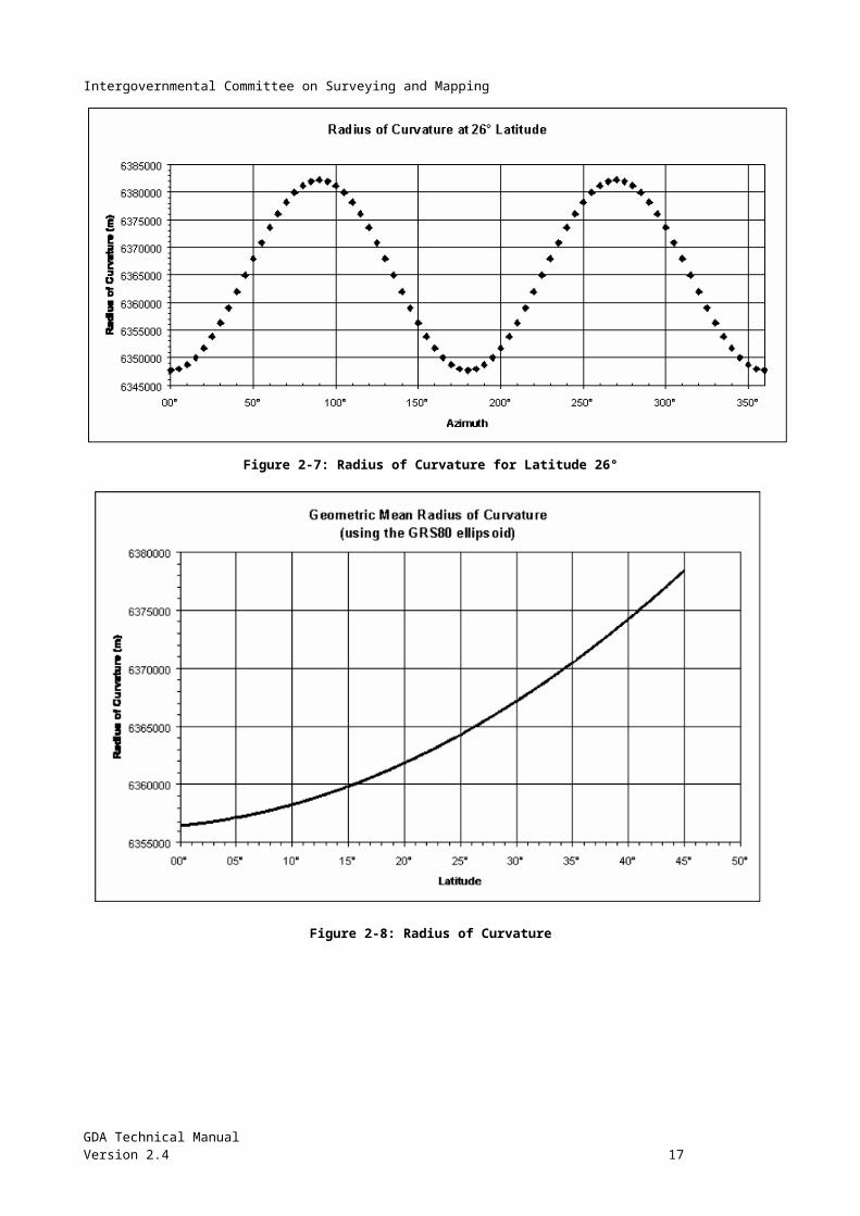
Radius of Curvature The radius of curvature is a function of latitude and for many applications the geometric mean radius (Rm ,) (Figure 2-7), can be used rather than the radius in the azimuth of the line ( Rα). However, there can be a large difference between the geometric mean radius and the radius in the azimuth of the line.
For high accuracy applications the radius of curvature in the azimuth of the line should be used.
Rm=( ρν )12 and
Rα= ( ρν )/ ( νcos2 α+ρ sin2 α )
where:
GDA Technical ManualVersion 2.4 11
Intergovernmental Committee on Surveying and Mapping
ρ=a (1−e2 )/ (1−e2 sin2 ϕ )3 /2
υ=a / (1−e2sin 2 ϕ)1/2
Figure 2-7: Radius of Curvature for Latitude 26°
Figure 2-8: Radius of Curvature
GDA Technical ManualVersion 2.4 12
Intergovernmental Committee on Surveying and Mapping
Chapter 3 Reduction of Measured Directions to the Ellipsoid
Excel Spreadsheet – Calculation of Deflection & Laplace Corrections
When a total station is levelled to make an angular observation (direction or azimuth) it is levelled according to the plumbline at that point, i.e. the normal to the geoid. This is generally different from the normal to the ellipsoid at the same point. This difference is known as the deflection of the vertical. The correction for this deflection is generally small, but should be applied for the highest quality results. Deflections of the vertical can be computed from astronomic and geodetic coordinates at the same point, or they can be produced from a geoid model such as AUSGeoid.
A further correction can be made to account for the fact that the normals at each end of the line are not parallel (the skew normal correction). This too is a small correction and "except in mountainous country, it can reasonably be ignored". (Bomford 1980).
Because they are related to a particular ellipsoid, deflections of the vertical, like geoid ellipsoid separations, will be different for different datums. Within Australia, the maximum deflection in terms of the GDA is of the order of twenty seconds of arc, which could result in a correction to an observed direction or azimuth approaching half a second of arc.
The Laplace correction defines the relationship between an astronomically observed azimuth and a geodetic azimuth. It can be a significant correction, of the order of several seconds of arc, and should always be applied to an astronomic azimuth before computing coordinates.
The formulae for these corrections are often given using the astronomic convention, with east longitude negative. However, the formulae used here have been rearranged to use the geodetic conventions, as used elsewhere in this manual (east longitude positive).
Formulae Direction (reduced) = Direction (measured) + Deflection correction + Skew normal correction + Laplace correction (Laplace for azimuth only)
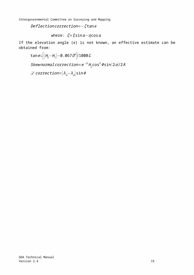
Deflectioncorrection=−ζ tan e
where: ζ =ξ sin α−η cosα
If the elevation angle (e) is not known, an effective estimate can be obtained from:
tan e¿ [ ( H2−H1 )−0.067 D2 ]/1000 D
Skew normalcorrection=e ' 2 H 2 cos2 Φsin (2 α ) /2 R
ℒ correction=( λ A− λG ) sin Φ
GDA Technical ManualVersion 2.4 13
Intergovernmental Committee on Surveying and Mapping
Sample Data
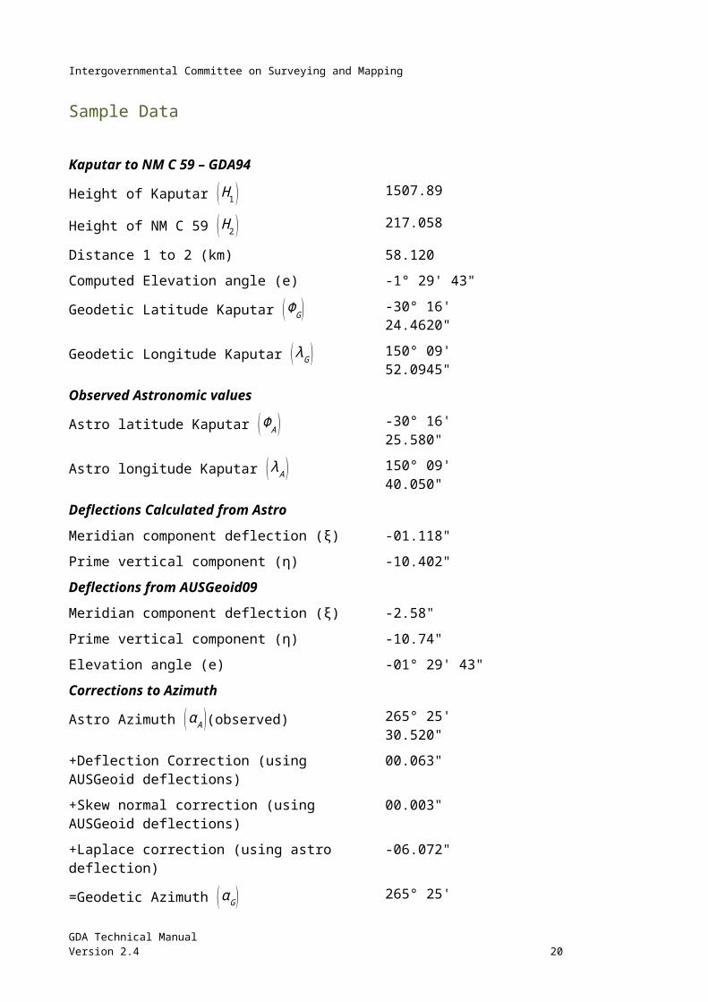
Kaputar to NM C 59 – GDA94
Height of Kaputar ( H1 ) 1507.89
Height of NM C 59 ( H 2 ) 217.058
Distance 1 to 2 (km) 58.120
Computed Elevation angle (e) -1° 29' 43"
Geodetic Latitude Kaputar (ΦG ) -30° 16' 24.4620"
Geodetic Longitude Kaputar ( λG ) 150° 09' 52.0945"
Observed Astronomic values
Astro latitude Kaputar (Φ A ) -30° 16' 25.580"
Astro longitude Kaputar ( λ A ) 150° 09' 40.050"
Deflections Calculated from Astro
Meridian component deflection (ξ) -01.118"
Prime vertical component (η) -10.402"
Deflections from AUSGeoid09
Meridian component deflection (ξ) -2.58"
Prime vertical component (η) -10.74"
Elevation angle (e) -01° 29' 43"
Corrections to Azimuth
Astro Azimuth (α A )(observed) 265° 25' 30.520"
+Deflection Correction (using AUSGeoid deflections) 00.063"
+Skew normal correction (using AUSGeoid deflections) 00.003"
+Laplace correction (using astro deflection) -06.072"
=Geodetic Azimuth (α G ) 265° 25' 24.514"
GDA Technical ManualVersion 2.4 14
Intergovernmental Committee on Surveying and Mapping
Symbols ξ the component of the deflection of the vertical in the meridian, in seconds of arc
= astronomic latitude – geodetic latitude
η the component of the deflection of the vertical in the prime vertical, in seconds of arc.
= (astronomic longitude – geodetic longitude) cosΦ
α Azimuth of the observed line – A (astronomic) G (geodetic)
e the elevation angle of the observed line (positive or negative)
R Radius of the earth in metres. For these small corrections, any reasonable estimate may be used.
H 2 Height of the reference station in metres.
H1 Height of the observing station in metres.
D Distance between the observing and reference stations in kilometres.
GDA Technical ManualVersion 2.4 15
Intergovernmental Committee on Surveying and Mapping
Chapter 4 Computations on the Ellipsoid Excel Spreadsheet – Vincenty's Formulae (Direct and Inverse)
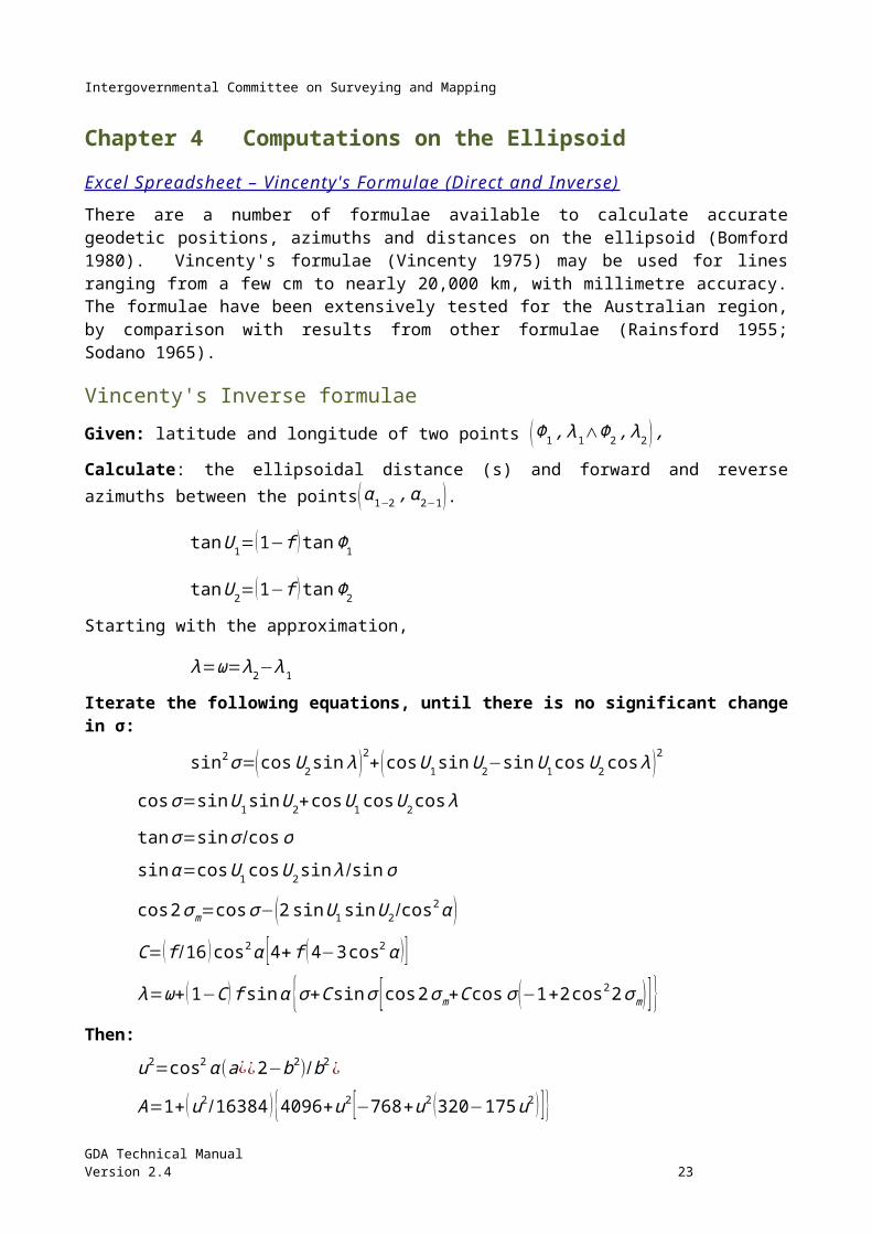
There are a number of formulae available to calculate accurate geodetic positions, azimuths and distances on the ellipsoid (Bomford 1980). Vincenty's formulae (Vincenty 1975) may be used for lines ranging from a few cm to nearly 20,000 km, with millimetre accuracy. The formulae have been extensively tested for the Australian region, by comparison with results from other formulae (Rainsford 1955; Sodano 1965).
Vincenty's Inverse formulae Given: latitude and longitude of two points (Φ1 , λ1∧Φ2 , λ2 ) ,
Calculate: the ellipsoidal distance (s) and forward and reverse azimuths between the points(α 1−2 , α 2−1 ).
tanU 1=(1−f ) tan Φ1
tanU 2=(1− f ) tan Φ2
Starting with the approximation,
λ=ω=λ2−λ1
Iterate the following equations, until there is no significant change in σ:
sin2 σ=(cosU 2 sin λ )2+( cosU 1sin U 2−sin U 1cos U2cos λ )2
cos σ=sin U1 sin U2+cosU1 cosU 2 cos λ
tan σ=sin σ /cosσsin α=cosU 1cosU 2sin λ /sin σ
cos2σ m=cos σ−(2sin U 1 sin U2/cos2 α )
C=( f /16 ) cos2 α [ 4+ f (4−3 cos2α ) ]λ=ω+ (1−C ) f sin α {σ+C sin σ [cos2 σm+C cosσ (−1+2 cos22σm ) ]}
Then:
u2=cos2 α (a¿¿2−b2) /b2¿
A=1+ (u2 /16384 ) {4096+u2 [−768+u2 (320−175u2 ) ]}B=(u2/1024 ) {256+u2 [−128+u2 (74−47 u2 ) ]}Δσ=B sin σ {cos2 σm+( B/4 ) [cos σ (−1+2 cos2 2σm )−(B /6 ) cos2σm (−3+4 sin2 σ ) (−3+4 cos2 2σ m )]}s=bA (σ−Δσ )
tan α1−2=( cosU 2sin λ )/ (cosU 1 sin U 2−sin U 1 cosU 2 cos λ )tan α2−1=( cosU1sin λ )/ (−sin U1 cosU2+cosU1 sin U2 cos λ )
GDA Technical ManualVersion 2.4 16
Intergovernmental Committee on Surveying and Mapping
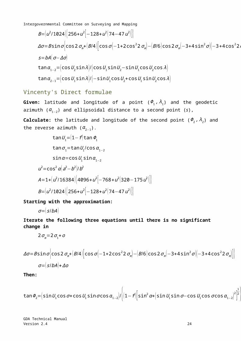
Vincenty's Direct formulae Given: latitude and longitude of a point (Φ1, λ1) and the geodetic azimuth (α 1−2) and ellipsoidal distance to a second point (s),
Calculate: the latitude and longitude of the second point (Φ2 , λ2) and the reverse azimuth (α 2−1).
tanU 1=(1− f ) tan Φ1
tan σ1=tanU 1/cos α1−2
sin α=cosU 1sin α 1−2
u2=cos2 α (a2−b2 ) /b2
A=1+ (u2 /16384 ) {4096+u2 [−768+u2 (320−175u2 ) ]}B=(u2/1024 ) {256+u2 [−128+u2 (74−47 u2 ) ]}
Starting with the approximation:
σ=( s/bA )
Iterate the following three equations until there is no significant change in
2 σm=2 σ1+σ
Δσ=B sin σ {cos2σm+( B/4 ) [cos σ (−1+2 cos2 2σm)−(B /6 ) cos2 σm (−3+4 sin2 σ ) (−3+4 cos2 2σ m )]}σ=( s/bA )+Δσ
Then:
tanΦ2=(sin U 1 cosσ+cosU1 sin σ cosα 1−2) /{(1−f ) [sin2 α+( sin U1sin σ−cosU 1cos σ cosα1−2 )2 ]12 }
tan λ=( sin σ sin α1−2 )/ (cosU 1cos σ−sin U 1 sin σ cos α 1−2 )
C=( f /16 ) cos2 α [ 4+ f (4−3cos2α ) ] ω=λ−(1−C ) f sin α {σ+C sin σ [cos 2σ m+C cos σ (−1+2 cos2 2σm)] }λ2=λ1+ω
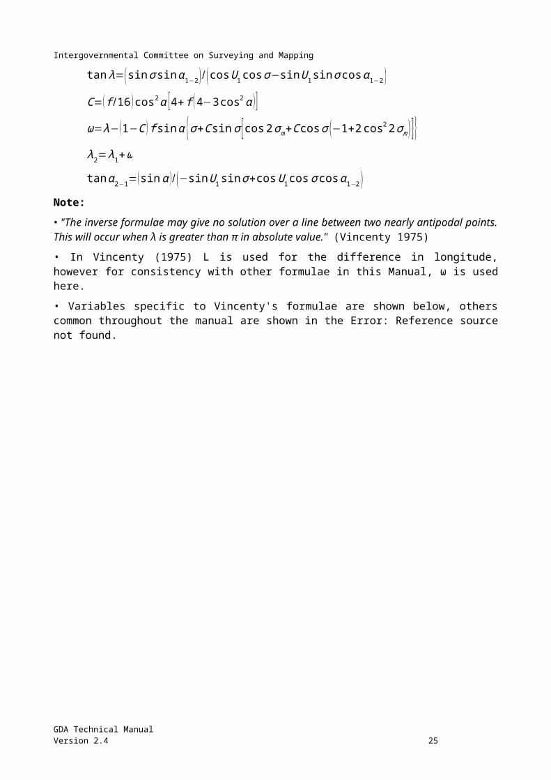
tan α2−1=(sin α )/ (−sin U 1 sin σ+cosU 1cos σ cosα 1−2 )Note:
• "The inverse formulae may give no solution over a line between two nearly antipodal points. This will occur when λ is greater than π in absolute value." (Vincenty 1975)
• In Vincenty (1975) L is used for the difference in longitude, however for consistency with other formulae in this Manual, ω is used here.
• Variables specific to Vincenty's formulae are shown below, others common throughout the manual are shown in the Error: Reference source not found.
GDA Technical ManualVersion 2.4 17
Intergovernmental Committee on Surveying and Mapping
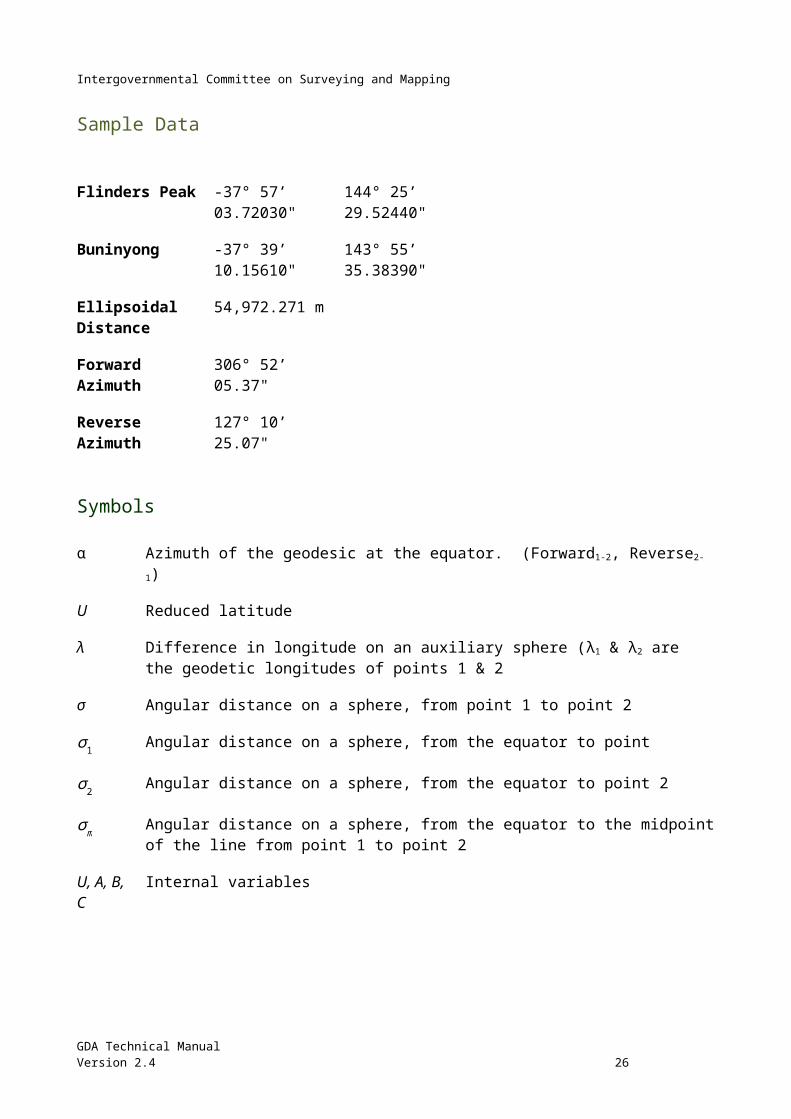
Sample Data
Flinders Peak -37° 57’ 03.72030" 144° 25’ 29.52440"
Buninyong -37° 39’ 10.15610" 143° 55’ 35.38390"
Ellipsoidal Distance 54,972.271 m
Forward Azimuth 306° 52’ 05.37"
Reverse Azimuth 127° 10’ 25.07"
Symbols
α Azimuth of the geodesic at the equator. (Forward1-2, Reverse2-1)
U Reduced latitude
λ Difference in longitude on an auxiliary sphere (λ1 & λ2 are the geodetic longitudes of points 1 & 2
σ Angular distance on a sphere, from point 1 to point 2
σ 1 Angular distance on a sphere, from the equator to point
σ 2 Angular distance on a sphere, from the equator to point 2
σ m Angular distance on a sphere, from the equator to the midpoint of the line from point 1 to point 2
U, A, B, C Internal variables
GDA Technical ManualVersion 2.4 18
Intergovernmental Committee on Surveying and Mapping
Chapter 5 Conversion between Ellipsoidal and Grid Coordinates
Excel Spreadsheet – Redfearn's Formulae
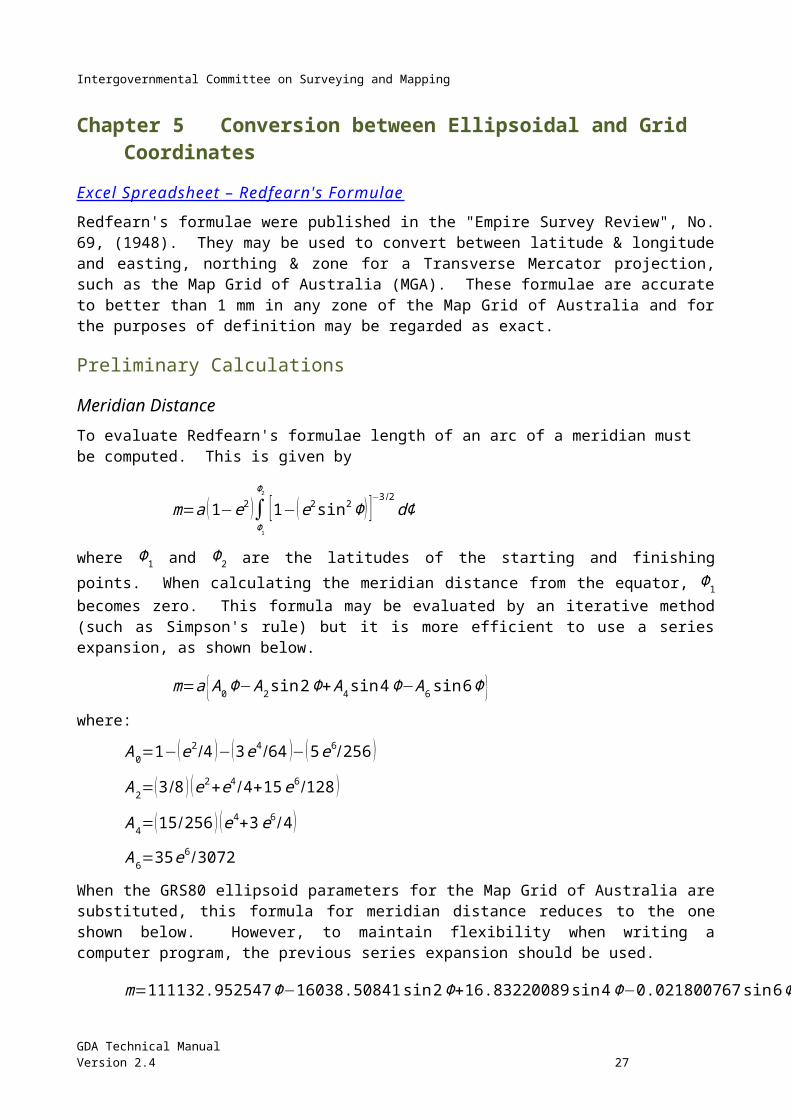
Redfearn's formulae were published in the "Empire Survey Review", No. 69, (1948). They may be used to convert between latitude & longitude and easting, northing & zone for a Transverse Mercator projection, such as the Map Grid of Australia (MGA). These formulae are accurate to better than 1 mm in any zone of the Map Grid of Australia and for the purposes of definition may be regarded as exact.
Preliminary Calculations Meridian Distance To evaluate Redfearn's formulae length of an arc of a meridian must be computed. This is given by
m=a ( 1−e2 )∫Φ1
Φ2
[ 1−(e2sin 2Φ ) ]−3 /2dΦ
where Φ1 and Φ2 are the latitudes of the starting and finishing points. When calculating the meridian distance from the equator, Φ1 becomes zero. This formula may be evaluated by an iterative method (such as Simpson's rule) but it is more efficient to use a series expansion, as shown below.
m=a {A0 Φ−A2sin 2Φ+ A4 sin 4Φ−A6 sin 6Φ }where:
A0=1−( e2/4 )−( 3 e4/64 )−(5 e6/256 )
A2= (3/8 ) (e2+e4/4+15 e6/128 )
A4=(15/256 ) ( e4+3e6/ 4 )
A6=35 e6 /3072
When the GRS80 ellipsoid parameters for the Map Grid of Australia are substituted, this formula for meridian distance reduces to the one shown below. However, to maintain flexibility when writing a computer program, the previous series expansion should be used.
m=111132.952547 Φ−16038.50841 sin2 Φ+16.83220089sin 4 Φ−0.021800767 sin 6Φ
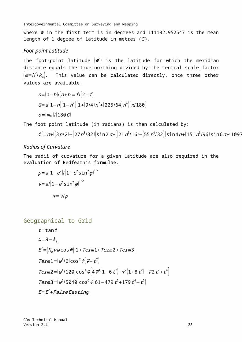
where Φ in the first term is in degrees and 111132.952547 is the mean length of 1 degree of latitude in metres (G).
Foot-point Latitude
The foot-point latitude (Φ ') is the latitude for which the meridian distance equals the true northing divided by the central scale factor(m=N ' /k0 ). This value can be calculated directly, once three other values are available.
n=(a−b )/ (a+b )=f / (2−f )
GDA Technical ManualVersion 2.4 19
Intergovernmental Committee on Surveying and Mapping
G=a (1−n ) (1−n2 ) ( 1+ (9/4 ) n2+ (225/64 )n4 ) (π /180 )
σ=(mπ )/ (180 G )
The foot point latitude (in radians) is then calculated by:
Φ '=σ+( (3 n/2 )−(27 n3 /32 )) sin2 σ+( (21 n2/16 )−(55 n4/32 ))sin 4 σ+( 151n3 /96 ) sin 6 σ+(1097 n4/512 ) sin 8 σ
Radius of Curvature The radii of curvature for a given Latitude are also required in the evaluation of Redfearn's formulae.
ρ=a (1−e2 )/ (1−e2 sin2 ϕ )3 /2
ν=a /(1−e2sin2 ϕ )1 /2
Ψ =ν / ρ
Geographical to Grid t=tanΦ
ω=λ−λ0
E'=( K 0 ν ωcosΦ) {1+Term1+Term2+Term3 }
Term1=( ω2/6 ) cos2Φ (Ψ −t 2 )
Term2=( ω4 /120 ) cos4 Φ [ 4Ψ 3 (1−6 t 2 )+Ψ 2 (1+8 t2 )−Ψ 2t 2+t 4 ]Term3=(ω6 /5040 ) cos6 Φ (61−479 t2+179 t 4−t 6 )
E=E'+False Easting
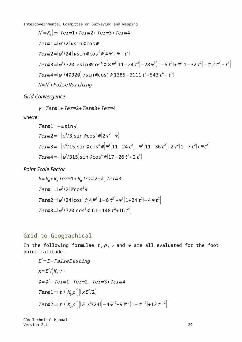
N '=K0 {m+Term1+Term2+Term3+Term4 }
Term1=( ω2/2 ) ν sin ΦcosΦ
Term2=( ω4 /24 ) ν sin Φcos3Φ ( 4Ψ 2+Ψ −t 2)
Term3=(ω6 /720 ) νsin Φ cos5 Φ [8Ψ 4 (11−24 t 2 )−28 Ψ 3 (1−6 t 2 )+Ψ 2 (1−32 t2 )−Ψ (2t 2 )+t 4 ]Term4=( ω8/ 40320 ) ν sinΦ cos7 Φ (1385−3111t 2+543t 4−t6 )
N=N '+False Northing
Grid Convergence
γ=Term1+Term2+Term3+Term 4
where:
Term1=−ωsin Φ
Term2=− (ω3 /3 ) sin Φcos2Φ (2Ψ 2−Ψ )
GDA Technical ManualVersion 2.4 20
Intergovernmental Committee on Surveying and Mapping
Term3=−(ω5/15 )sin Φ cos4 Φ [Ψ 4 (11−24 t2 )−Ψ 3 (11−36 t 2 )+2 Ψ 2 (1−7 t2 )+Ψt2 ]Term4=− (ω7 /315 ) sin Φcos6 Φ (17−26 t2+2 t 4 )
Point Scale Factor k=k0+k0Term1+k0Term2+k0Term3
Term1=( ω2/2 ) Ψ cos2 Φ
Term2=( ω4 /24 ) cos4 Φ [4 Ψ 3 (1−6 t 2)+Ψ 2 (1+24 t 2 )−4 Ψ t 2 ]Term3=(ω6 /720 )cos6 Φ (61−148 t 2+16 t 4 )
Grid to Geographical In the following formulae t , ρ , ν and Ψ are all evaluated for the foot point latitude.
E'=E−False E asting
x=E' / (K 0 ν ')Φ=Φ'−Term1+Term2−Term3+Term4
Term1=(t '/ ( K0 ρ ') ) ( x E '/2 )
Term2=( t ' /( K 0 ρ') ) ( E' x3/24 ) [−4 Ψ '2+9 Ψ ' (1−t '2 )+12 t ' 2 ]Term3=( t ' /( K 0 ρ') ) ( E' x5 /720 ) [ 8Ψ ' 4 (11−24 t ' 2)−12Ψ ' 3 (21−71t '2 )+15 Ψ '2 (15−98 t ' 2+15 t '4 )+180 Ψ ' (5 t ' 2−3 t ' 4 )+360 t ' 4 ]Term4=(t ' /( K0 ρ' ) ) ( E' x7 /40320 ) (1385+3633 t '2+4095t '4+1575 t ' 6 )
ω=Term1−Term2+Term3−Term4
Term1=x sec Φ'
Term2=( x3/6 ) sec Φ' (Ψ '+2 t '2 )
Term3=( x5 /120 ) secΦ ' [−4 Ψ '3 (1−6 t '2 )+Ψ ' 2 (9−68 t '2 )+72 Ψ ' t ' 2+24 t ' 4 ]Term4=( x7 /5040 ) secΦ' (61+662t '2+1320 t '4+720t '6 )λ=λ0+ω
Grid Convergence x=E ' /k0 ν '
t '=tan Φ'γ=Term1+Term2+Term3+Term 4Term1=−t ' x
Term2=( t ' x3/3 ) (−2 Ψ '2+3Ψ '+t ' 2 )
GDA Technical ManualVersion 2.4 21
Intergovernmental Committee on Surveying and Mapping
Term3=(−t ' x5/15 ) [Ψ ' 4 (11−24 t ' 2)−3 Ψ '3 ( 8−23 t ' 2 )+5Ψ '2 (3−14 t '2 )+30 Ψ ' t '2+3 t ' 4 ]Term4=( t' x7/315 ) (17+77 t '2+105 t ' 4+45 t ' 6 )
Point Scale
x=( E' 2/k02 ρ' ν ' )
K=k0+k 0Term1+k 0Term2+k 0Term3
Term1=x /2
Term2=( x2/24 ) [4 Ψ ' (1−6 t '2 )−3 (1−16 t '2 )−24 t ' 2/Ψ ' ]Term3=x3/720
Sample Data Flinders Peak
MGA94 (zone 55) E 273 741.297 N 5 796 489.777
GDA94 -37° 57' 03.7203" 144° 25' 29.5244"
Convergence -01° 35' 03.65"
Point scale factor 1.000 230 56
GDA Technical ManualVersion 2.4 22
Intergovernmental Committee on Surveying and Mapping
Chapter 6 Grid Calculations Excel Spreadsheet – Grid Calculations
Coordinates and the relationships between them are rigorously calculated using ellipsoidal formulae. These formulae produce geodetic coordinates (latitude and longitude), azimuths and ellipsoidal distances and are well within the scope of modern personal computers.
Redfearn's formulae can then be used to rigorously produce grid coordinates (easting, northing & zone), together with the point scale factor and convergence, from the geodetic coordinates; these can then be used to compute grid distances and grid bearings. Alternatively, the formulae given in this section can be used to compute grid coordinates, grid distances and grid bearings.
Grid Bearing and Ellipsoidal Distance from MGA94 coordinates The following formulae provide the only direct method to obtain grid bearings and ellipsoidal distance from MGA94 coordinates.
tanθ1=(E2' −E1
' )/ ( N2−N 1 )or
cot θ1= ( N2−N1 )/ (E2' −E1
' )L=( E2
' −E1' ) /sin θ1
¿ ( N2−N 1) /cosθ1
K=k0 {1+[ (E1' 2+E1
' E2' +E2
' 2 )/6 rm2 ] [1+( E1
' 2+E1' E2
' +E2' 2) /36 rm
2 ]}s=L/K
δ 1} =- left ({N} rsub {2} - {N} rsub {1} right ) left ({E} rsub {2} rsup {'} +2 {E} rsub {1} rsup {'} right ) left [1- {left ({E} rsub {2} rsup {'} +2 {E} rsub {1} rsup {'} right )} ^ {2} /27 {{r} rsub {m}} ^ {2} right ] / {{6r} rsub {m}} ^ {2} left lbrace radians right rbrac ¿
δ 1} =206264.8062 {δ} rsub {1} left lbrace seconds right rbrac¿
δ 2} = left ({N} rsub {2} - {N} rsub {1} right ) left (2 {E} rsub {2} rsup {'} + {E} rsub {1} rsup {'} right ) left [1- {left (2 {E} rsub {2} rsup {'} + {E} rsub {1} rsup {'} right )} ^ {2} /27 {{r} rsub {m}} ^ {2} right ] / {{6r} rsub {m}} ^ {2} left lbrace radians right rbrac ¿
δ 2} =206264.8062 {δ} rsub {2} left lbrace seconds right rbrac¿
β1=θ1−δ1
β2=θ1 ±180 °−δ2
The mean radius of curvature can be calculated as shown below, using an approximate value for the mean latitude(Φm
' ). The approximate mean latitude can be calculated in two steps, with an accuracy of about two minutes of arc, using the formulae shown below. This approximation is derived from the formulae for meridian distance used with Redfearn's formulae and the constants shown are the values a A1 anda A2, computed for GDA.
N '=N−False Northing
Nm' =(N1
' +N2' )/2
Φm' ¿
GDA Technical ManualVersion 2.4 23
Intergovernmental Committee on Surveying and Mapping
Φm' ¿
ρm=a (1−e2 )/ (1−e2sin 2Φm' )3 /2
νm=a /(1−e2 sin2Φm' )1 /2
rm2=ρm νm ko
2
MGA94 Coordinates from Grid bearing and Ellipsoidal Distance This computation is commonly used when the coordinates of one station are known and the grid bearing and ellipsoidal distance from this station to an adjacent station have been determined. The bearing and distance are applied to the coordinates of the known station to derive the coordinates of the unknown station and the reverse grid bearing. The formulae shown are accurate to 0.02" and 0.1 ppm over any 100 kilometre line in an MGA zone. For lower order surveys:
• the underlined terms are often omitted
• the latitude function 1/6r2 becomes a constant and
• the formulae for K and δ are replaced by simplified versions
Formulae First calculate approximate coordinates for the unknown station:
E1' =E1−500 000
E2' ≈ E '1+k1 s sin β1
N 2−N1 ≈ k1 s cos β1
If not already known the point scale factor (k 1) may be approximated by:
k1 ≈ 0.9996+1.23 E '2 10−14
K=k0 {1+[ (E1' 2+E1
' E2' +E2
' 2 )/6 rm2 ] [1+( E1
' 2+E1' E2
' +E2' 2) /36 rm
2 ]}L=sK
sin δ 1=−( N2−N 1 )( E2' +2 E1
' ) [1−( E2' +2 E1
' )2/27 rm
2 ]/6 rm2
θ=β1+δ1
sin δ 2=( N 2−N 1) (2 E2' +E1
' ) [1−(2 E2' +E1
' )2/27 rm
2 ]/6 rm2
β2=θ ± 180°−δ 2
ΔE=L sin θΔN=L cosθ
E2=E1+ ΔE
N 2=N1+ ΔN
GDA Technical ManualVersion 2.4 24
Intergovernmental Committee on Surveying and Mapping
The mean radius of curvature can be calculated as shown below, using an approximate value for the mean latitude(Φm
' ). The approximate mean latitude can be calculated in two steps, with an accuracy of about two minutes of arc, using the formulae shown below. This approximation is derived from the formulae for meridian distance used with Redfearn's formulae and the constants shown are the values aA0 andaA2, computed for GDA.
N '=N−False Northing
Nm' =(N1
' +N2' )/2
Φm' ¿
Φm' ¿
ρm=a (1−e2 )/ (1−e2sin 2Φm' )3 /2
νm=a /(1−e2 sin2Φm' )1 /2
rm2=ρm νm k0
2
Zone to Zone Transformations If a point lies within 0.5° of a zone boundary, it is possible to compute the grid coordinate of the point in terms of the adjacent zone. This can be done by:
1. converting the known grid coordinates to latitude and longitude using Redfearn's formulae, and then converting back to grid coordinates in terms of the adjacent zone, or
2. using the formulae shown below (Jordan and Eggert 1941; Grossmann 1964). These formulae have an accuracy of 10 mm anywhere within 0.5° of a zone boundary.
Formulae
tan J1=[ωz2 cos2 Φz (1+31 tan2 Φz )−6 (1+e ' 2cos2Φz )]/ [18 ωz sin Φz (1+e '2 cos2 Φz )]
H 1=−3 ωz2sin Φz cosΦz/ ( ρ z cosJ 1 )
E2=500000−E z' +(E1
' −E z' )cos2 γ z−( N1−N z ) sin 2 γ z+H1 L2 sin (2θ z+J1 )
N2=N z+( N1−N z ) cos2 γ z+¿ (E1' −E z
' )sin 2 γ z+ H 1 L2 cos (2θ z+J1 )¿
where: Z is a point on the zone boundary,
E1 , N 1 are the known coordinates of the point to be transformed,
E2 , N 2 are the coordinates of the point in terms of the adjacent zone,
θz is the plane bearing from Z to the point to be transformed.
GDA Technical ManualVersion 2.4 25
Intergovernmental Committee on Surveying and Mapping
Traverse Computation with Grid Coordinates, using Arc-to-Chord Corrections and Line Scale Factors With the power of modern computers, traverses can be rigorously computed on the ellipsoid, using formulae such as those shown in Chapter 4. The geographic results from these computations can then be rigorously converted to grid coordinates using Redfearn's formulae. However if necessary, the computation can be varied to suit the requirements of the job:
• the arc-to-chord corrections and line scale factors can be ignored and the traverse computed using the formulae of plane trigonometry;
• if good quality maps showing the MGA94 Grid are available, traverse stations may be plotted by inspection and the approximate coordinates scaled with sufficient precision to enable computation of the arc-to-chord corrections and line scale factors;
• the arc-to-chord corrections and line scale factors can be computed precisely, and the method becomes first order anywhere in a MGA94 grid zone.
The precision obtained should be closely balanced against the labour involved, though with modern Personal Computers and available software, the difference between a rigorous and approximate calculation is trivial. Prior to precise computation, approximate coordinates and bearings may be carried through the traverse, using uncorrected field measurements, to ensure that the observations are free of gross errors. A diagram of the traverse, approximately to scale, is often useful.
Basic Outline There are many ways of arranging the computation. Essentially, the work is split into stages:
1. Approximate Eastings and Northings are computed from observed angles and distances;
2. Arc-to-chord corrections and line scale factors are computed from the approximate coordinates and applied to the observations to give plane angles and plane distances;
3. Precise coordinates are computed by plane trigonometry;
4. Misclosure in grid bearing and position is analysed and the traverse or figure adjusted as required.
For precise computation, each line is rigorously computed before the next line is calculated, so that errors in the approximate coordinates do not accumulate. True Eastings (E') and differences in northing (∆N) are the quantities carried through the computation. Sign conventions may be disregarded and signs determined by inspection of a traverse diagram.
Formulae and Symbols If the underlined terms shown in the preceding sections of this chapter are omitted, the errors for a 100 kilometre line running north and south on a zone boundary do not exceed 0.08" in bearing and 0.25 ppm in distance. For traverses of lower order, simplified formulae can be used. For short lines near a central meridian it may be possible to omit the arc-to-chord corrections and line scale factors and compute the traverse with observed angles and distances, using the formulae of plane trigonometry.
GDA Technical ManualVersion 2.4 26
Intergovernmental Committee on Surveying and Mapping
If the symbol δ 21is used for the arc-to-chord correction at station 2 to station 1 and δ 23 for the correction at station 2 to station 3, and the angles are measured clockwise from station 1 to station 3, then the angle P2 (plane) at station 2 is obtained from the angle 02 (observed) by:
P2=02+δ23−δ21
where angles are measured clockwise only.
Computations of ARC-TO-CHORD Corrections and scale factors Although there are several ways of arranging the computation, the following is recommended:
1. Compute the grid bearing to the "forward" station by applying the observed horizontal angle at the "occupied" station to the known grid bearing of the "rear" station;
2. Compute the point scale factor at the "occupied" station and multiply the ellipsoidal distance to the "forward" station by this factor;
3. Using the distance obtained and the forward grid bearing, compute approximate coordinates of the "forward" station by plane trigonometry;
4. Using the coordinates of the "occupied" station and the approximate coordinates of the "forward" station, compute the arc-to-chord correction at the "occupied" station and the line scale factor. If the line crosses the central meridian, (E1, E2) is negative;
5. Add the arc-to-chord correction to the forward grid bearing to obtain the plane bearing and multiply the spheroidal distance by the line scale factor to obtain the plane distance;
6. Using the plane bearing and plane distance, compute the coordinates of the "forward" station by plane trigonometry;
7. Compute the arc-to-chord correction from the new station to the previously occupied station and add this to the plane bearing reversed by 180° to obtain the reverse grid bearing from the new station.
The above process is repeated for each new line of a traverse with the reverse grid bearing of the previous line becoming the known grid bearing to the rear station.
Sample Data Flinders Peak Buninyong
MGA94 (zone 55) E 273 741.297
N 5 796 489.777
E 228 854.052
N 5 828 259.038
Ellipsoidal Distance (m)
54,972.271
Plane Distance (m) 54,992.279
Grid Bearing 305° 17' 01.72" 125° 17' 41.86"
Arc to chord +19.47" -20.67"
GDA Technical ManualVersion 2.4 27
Intergovernmental Committee on Surveying and Mapping
Line scale factor 1.000 363 97
GDA Technical ManualVersion 2.4 28
Intergovernmental Committee on Surveying and Mapping
Chapter 7 Transformation of Coordinates The coordinates of a point will change depending on which datum the coordinates are referred to. To change a coordinate from one datum to another, a mathematical process known as transformation is used. This may be done in two or three dimensions and requires a number of points with positions known in terms of both datums ('common' points). The accuracy of the transformation depends on the method chosen and the accuracy, number and distribution of the 'common points'.
For transforming AGD66 or AGD84 coordinates to GDA the grid transformation process is the most accurate. For the sake of consistency it is recommended for all transformations in Australia. However, it is recognised that there are different user requirements, so less accurate transformation methods are also provided. As the different methods will give different results, metadata should be maintained, giving the accuracy and method used to obtain the transformed positions.
The transformation parameters supplied in this manual are between AGD and GDA94 and supersede all previous parameters, including those between AGD and WGS84, as GDA94 is the same as WGS84 for most practical applications. Transformation from ITRF to GDA is not covered in detail in this manual, but is discussed in Chapter 1, with a link to more detailed information. Software developed to support transformation from ITRF to GDA can be downloaded from the GDA Technical Manual Web page. In particular the RapidMap prepared downloadable.
High Accuracy Transformation (Grid Transformation) Excel Spreadsheet – Test Data for Grid Transformation
National Transformation Grids for AGD66 and AGD84 are available from the GDA Technical Manual web site.
Ideally, the transformation process should be:
• “Simple to apply
• computationally efficient
• unique in terms of the solution it provides
• rigorous
The first two criteria are necessitated by the large volumes of data that will have to be transformed. The second two are based on the premise that the transformation process must not compromise the quality or topology of the original data. In this regard it is argued that, with careful development it is possible to improve data accuracy by incorporating a distortion model in the transformation process." (Collier, Argeseanu et al. 1998).
In 1997, ICSM adopted an approach for Australia that fitted the above criteria. This method is the same as that adopted in Canada, in that it uses files of coordinate shifts that compensate for distortions in the original data, as well as transforming between datums. The complex mathematical processing, based on many common points, is done prior to the production of the files of coordinate shifts (Collier, Argeseanu et al. 1998) and the user only has to perform a simple interpolation to obtain the required shifts, followed by a simple addition to perform the transformation. The files of coordinate shifts are provided in the Canadian format known as National Transformation version 2 (NTv2). The Australian NTv2 transformation files are provided in the binary format, but software provided by ICSM jurisdictions can readily convert them to ASCII format. Although there was some
GDA Technical ManualVersion 2.4 29
Intergovernmental Committee on Surveying and Mapping
minor initial confusion with the original Australian-produced binary files, both the ASCII and binary formats now conform to the Canadian format that is used in many GIS packages. An in-depth explanation of the format can be found in Appendix C of the "GDAit" User Guide and the GDAit Software Documentation available from https://www.propertyandlandtitles.vic.gov.au/surveying/geodetic-survey/geocentric-datum-of-australia.
Interpolation software Initially, each State and Territory produced a transformation grid file for its area and NSW and Victoria combined theirs into a single grid (SEA). These transformation grid files transformed from either AGD66 or AGD84, depending on which version of AGD was previously adopted by that jurisdiction. Several States also produced software to interpolate and apply the transformation shifts, either interactively or from a file of coordinates, using any grid file in NTv2 format. Victoria produced (GDAit), Queensland (GDAy) and NSW (Datumtran and GEOD).
National Transformation Grids Two national transformation grid files are now available to replace the previous State & Territory grid files (Collier and Steed 2001).
1. A complete national coverage from AGD66 to GDA94. This coverage was generated using the latest algorithms with data from the previous AGD66 State & Territory grid files and AGD66 & GDA94 data from the National Geodetic Data Base. In NSW and Victoria the on-shore and close coastal areas of the previous combined State grid have been included in the national grid, but elsewhere there may be differences. These differences are generally small but may be larger near the State borders and in areas where there was little or no common data (e.g. offshore). The AGD66 national file also covers the offshore areas out to the Exclusive Economic Zone (EEZ). Although still in NTv2 format, a simple conformal (7-parameter) transformation was used to generate the shifts in these offshore areas (See Figure 7-9).
Figure 7-9 AGD66 to GDA94 Transformation Grid Coverage
GDA Technical ManualVersion 2.4 30
Intergovernmental Committee on Surveying and Mapping
2. A coverage from AGD84 to GDA94 for the States that previously adopted AGD84 (Queensland, South Australia and Western Australia). This coverage was produced by merging the existing Queensland, South Australian and West Australian transformation files and differs slightly from the previous State files only near the merged borders (see Figure 7-10).
Figure 7-10 AGD 84 to GDA94 Transformation
For mathematical convenience and to suit the rectangular convention of the NTv2 format, the national grids extend outside the Australian EEZ in some places, but these extents do not infer any rights, nor do they imply the use of AGD or GDA94 coordinates in these areas.
For the convenience of those working only in a local area, software is also available to extract user defined areas from the national grid files from the ICSM GDA webpage.
To assist in the testing of transformation systems using these national grid files, a spreadsheet is available containing sample input and output for both the AGD66 & AGD84 grids on the ICSM GDA webpage.
Medium Accuracy Transformation 3-Dimensional Similarity Transformation Excel Spreadsheet – Cartesian to Geodetic & 7-Parameter Transformation
Provided the rotation angles are small (a few seconds), the relationship between two consistent, three dimensional coordinate systems can be completely defined by a seven parameter similarity transformation (three origin shifts, three rotations and a scale change) (Harvey 1986).
The transformation is a relatively simple mathematical process, but because this technique is in terms of Earth-centred Cartesian coordinates (X Y Z), the points to be transformed must be converted to this coordinate type. This means that ellipsoidal heights are used on input and are produced on output; however, provided the ellipsoidal height entered is a reasonable estimate (within a few hundred metres) there will be negligible effect on the transformed horizontal position (millimetres).
GDA Technical ManualVersion 2.4 31
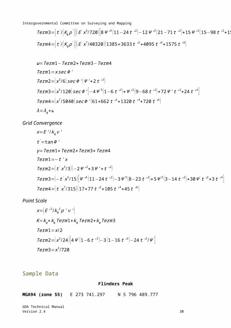
Intergovernmental Committee on Surveying and Mapping
National parameters to convert between AGD84 and GDA94 have been developed and have an estimated accuracy of about 1 m. Because of the inconsistent nature of the AGD66 coordinate set, it is not possible to compute a set of national AGD66/GDA94 parameters with acceptable accuracy, but they can be computed for local regions. Some authorities have computed regional AGD66/GDA94 parameters (see Regional Transformation Parameters from AGD66 to GDA94).
National parameters have been computed to transform between AGD84 and GDA94 using the similarity method. These parameters were computed from 327 points across Australia, which had both AGD84 and GDA94 coordinates, well determined AHD heights (by spirit levelling), and which were GPS points in the national GDA94 adjustment. The resulting parameters are shown in Table 7-7.
Note: These parameters can be used for projects of medium accuracy (of the order 1 m). More accurate methods must be used for projects requiring greater accuracy. Although this method transforms the height, direct transformation of the height using the geoid-ellipsoid separation is easier and generally more accurate.
Parameters Table 7-7: National parameters – AGD84 and AGD66 to GDA94
Parameter AGD84 AGD66
DX (m) -117.763 -117.808
DY (m) -51.510 -51.536
DZ (m) 139.061 137.784
RX (secs) -0.292 -0.303
RY (secs) -0.443 -0.446
RZ(secs) -0.277 -0.234
Sc( ppm) -0.191 -0.290
The AGD84 parameters were tested using points additional to the initial 327, which had both AGD84 and GDA94 coordinates. A summary of these tests is shown in Table 7-8. The AGD66 parameters were developed as first step in the production of the national transformation grid and used 9,761 common points.
Table 7-8: AGD ↔ GDA94 parameters – residuals from 1571 points (lat/long) and 65 points (ellip. ht.)
Average (m) Std. Dev. (m) Max (m)
Min (m)
Latitude -0.10 0.38 1.03 -1.48
Longitude
-0.08 0.38 1.14 -2.50
Ellip. Ht. 0.14 0.37 0.95 -0.66
GDA Technical ManualVersion 2.4 32
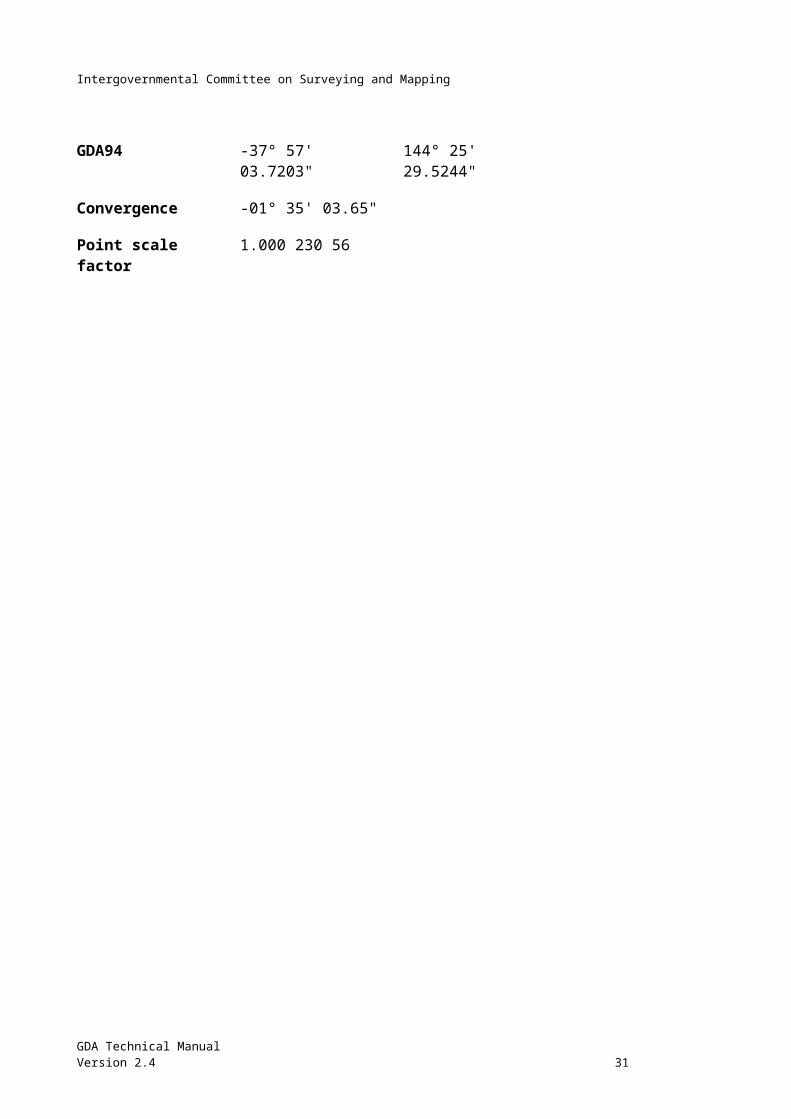
Intergovernmental Committee on Surveying and Mapping
Formulae Once the positions have been converted to Earth-centred Cartesian coordinates, the similarity transformation is performed by a simple matrix operation:
x 'y 'z '
=|ΔxΔyΔz|+ (1+Sc∗10−6 ) R|X
YZ|
Where R is the combined matrix of rotations about the X, Y and Z axes, in that order, i.e.
R=R x R y R z
In its full form this combined rotation matrix is:
| cos R y cos R z cos R y sin R z −sin R y
sin R x sin R y cos R z−cos Rx sin R z sin Rx sin Ry sin R z+cos Rx cos R z sin R x cos R y
cos Rx sin R y cos Rz+sin Rx sin R z cos Rx sin R y sin R z−sin Rx cos R z cos Rx cos Ry|
But for small rotations (a few seconds) it is closely approximated by the matrix below (where the rotations are in radians):
| 1 R z −R y
−R z 1 R x
R y −Rx 1 |Warning There are two different ways of applying the sign conventions for the rotations. In both cases the sign convention is the same (a positive rotation is an anti-clockwise rotation, when viewed along the positive axis towards the origin) but:
1. The International Earth Rotation Service (IERS) assumes the rotations to be of the position around the coordinate axes, while
2. The method historically used in Australia assumes the rotations to be of the coordinate axes.
The only difference in the formula is a change in the signs of the angles in the rotation matrix. If the sign of the rotation parameters and the formulae used are consistent the correct results will be obtained. The only way to be absolutely sure which method or parameters are required is to test them using a known input and output for a set of parameters as shown in Table 7-9. If necessary the situation can be rectified by simply changing the sign of the rotation parameters.
Table 7-9: Sample input and output, using the national AGD84 Similarity parameters
AGD84 GDA94
Latitude S 37° 39' 15.5647" S 37° 39' 10.1598"
GDA Technical ManualVersion 2.4 33
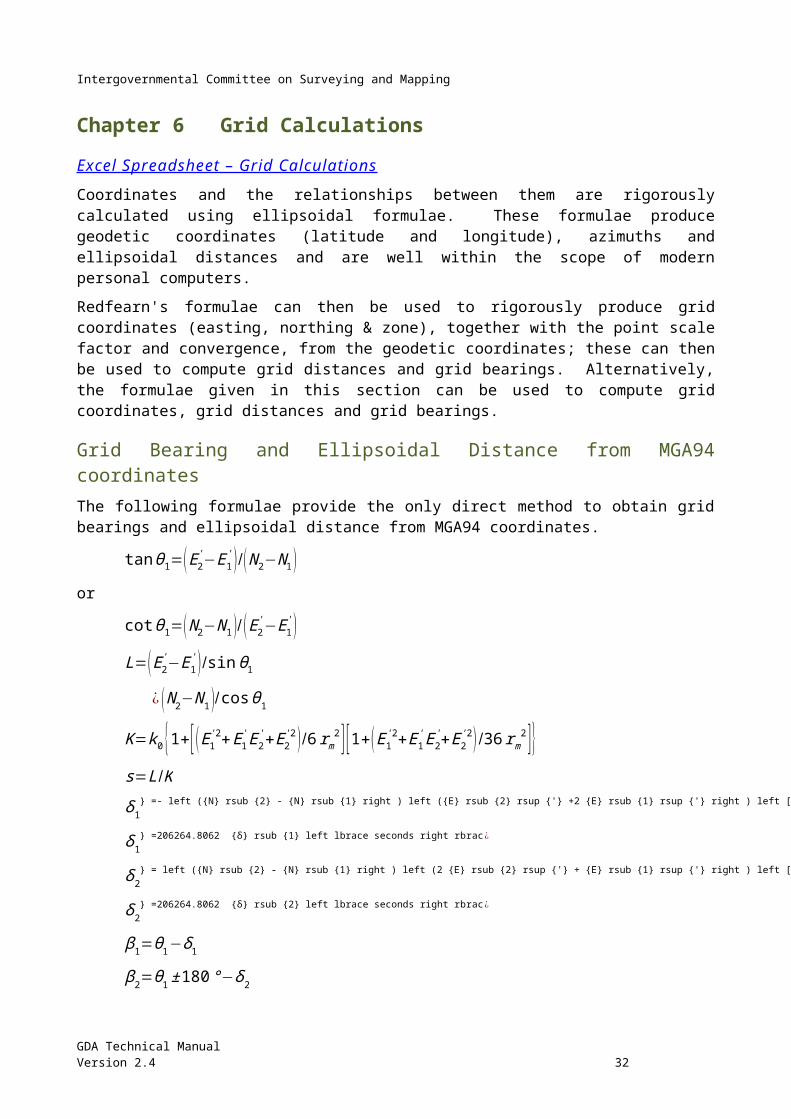
Intergovernmental Committee on Surveying and Mapping
Longitude E 143° 55' 30.5501" E 143° 55' 35.3730"
Ellipsoidal height 749.671 m 737.574 m
Table 7-10: Sample input and output, using the national AGD66 Similarity parameters
AGD66 GDA94
Latitude S 37° 39' 15.5571" S 37° 39' 10.1757"
Longitude E 143° 55' 30.6330" E 143° 55' 35.4093"
Ellipsoidal height 749.671 m 737.739 m
Conversion between Geographical and Cartesian Coordinates To convert between Geographical coordinates (latitude, longitude and ellipsoidal height) and three dimensional, Earth-centred Cartesian coordinates (X, Y, Z), the formulae given below are used.
It is essential that the appropriate reference ellipsoid is used and also to note that ellipsoidal heights must be used on input and are produced on output.
Formulae
Geographical to Cartesian
X=(ν+h )cosΦ cos λY= (ν+h ) cosΦsin λZ={(1−e2) ν+h}sin Φ
Cartesian to Geographical
tan λ=Y / XtanΦ=(Z (1−f )+e2 a sin3 u ) /( (1− f ) ( p−e2a cos3u ))
h=p cosΦ+Z sin Φ−a (1−e2sin2 Φ)1 /2
Where:
ν=a / {(1−e2 sin2Φ )1 /2}e2=2 f −f 2
h=N+H
Where:
p=( X2+Y 2 )1/2
tanu=( Z / p ) [ (1− f )+( e2 a/r ) ]
r=( p2+Z2 )1 /2
Example using GDA94 (GRS80 ellipsoid)
Latitude -37° 39' 10.1598" -4087095.384 X
Longitude 143° 55' 35.3730" 2977467.494 Y
Ellipsoidal height
737.574 m -3875457.340 Z
GDA Technical ManualVersion 2.4 34
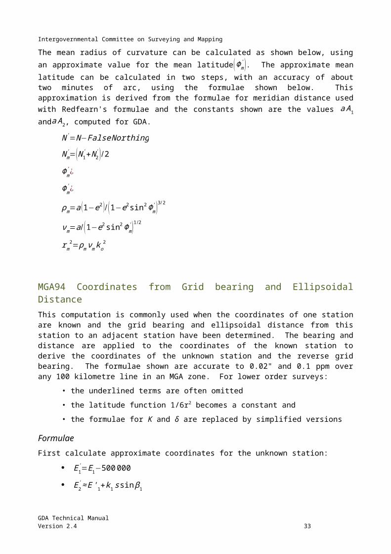
Intergovernmental Committee on Surveying and Mapping
Regional Transformation Parameters from AGD66 to GDA94 Although it is possible to compute national similarity transformation parameters between AGD84 & GDA94, AGD66/GDA94 similarity transformation parameters can only be accurately computed for smaller areas where AGD66 is more consistent. This was done as a first step in the development of the jurisdiction transformation grids and where the more accurate methods are not appropriate, these parameters may be used.
The parameters shown are only valid for transformation between AGD66 and GDA94 for the area indicated. They have an accuracy of only about 1 metre and the transformation grid method is preferred if at all possible.
Table 7-11: Regional Similarity transformation parameters – AGD66 to AGD94
Parameter
A.C.T Tasmania VictoriaNSW
NorthernTerritory
DX (m) -129.193 -120.271 -119.353 -124.133
DY (m) -41.212 -64.543 -48.301 -42.003
DZ (m) 130.730 161.632 139.484 137.400
RX (secs) -0.246 -0.217 -0.415 0.008
RY (secs) -0.374 0.067 -0.260 -0.557
RZ (secs) -0.329 0.129 -0.437 -0.178
Sc (ppm) -2.955 2.499 -0.613 -1.854
Table 7-12: Sample input and output, using A.C.T. Similarity parameters
AGD66 GDA94
Latitude S 35° 18' 18.0000" S 35° 18' 12.3911"
Longitude E 149° 08' 18.0000" E 149° 08' 22.3382"
Ellipsoidal height 600.000 m 601.632 m
Table 7-13: Sample input and output, using Tasmanian Similarity parameters
AGD66 GDA94
Latitude S 42° 53' 03.0000" S 42° 52' 57.6165"
GDA Technical ManualVersion 2.4 35
Intergovernmental Committee on Surveying and Mapping
Longitude E 147° 19' 19.0000" E 147° 19' 23.9274"
Ellipsoidal height 100.000 m 77.163 m
GDA Technical ManualVersion 2.4 36
Intergovernmental Committee on Surveying and Mapping
Table 7-14: Sample input and output, using the Victoria/NSW Similarity parameters
AGD66 GDA94
Latitude S 33° 25' 25.12340 S 33° 25' 19.48962"
Longitude E 149° 34' 34.34560" E 149° 34' 38.58555"
Ellipsoidal height
603.345 m 610.873 m
Low Accuracy Transformation Molodensky's Formulae Excel Spreadsheet – Molodensky’s Transformation
Molodensky's transformation method uses an average origin shift (at the centre of the earth) and the change in the parameters of the two ellipsoids. This method is often used in hand-held GNSS receivers with the old parameters published by United States National Imagery and Mapping Agency (NIMA) in their Technical Report 8350.2. These DMA parameters are now superseded by AGD66/84↔GDA94 parameters which have an estimated accuracy of about 5 metres:
Transformation from AGD66 or AGD84 to GDA94
Abridged Molodensky Formulae & Parameters The United States Defense Mapping Agency previously published parameters for use with Molodensky's formulae, to convert between either AGD66 or AGD84 and WGS84 (DMA 1987). As for most practical purposes WGS84 is the same as GDA94, the same formula may continue to be used, but improved parameters are now available to convert between either AGD66 or AGD84 and GDA94 (AUSLIG 1997). It should be noted that these formulae require ellipsoidal height on input and give ellipsoidal height on output; however, the height component may be ignored if not required.
Note: This transformation method should only be used for low accuracy projects (accuracy no better than 5 m). Other methods are available for higher accuracy projects.
The AGD66/GDA94 parameters were derived from 161 points across Australia, which had both AGD66 and GDA94 coordinates, each of which also had a spirit levelled height. The AGD84/GDA94 parameters were similarly derived using 327 common points. These parameters are shown in Table 7-15.
GDA Technical ManualVersion 2.4 37
Intergovernmental Committee on Surveying and Mapping
Parameters Table 7-15: Parameters – AGD66 & AGD84 to GDA94
AGD66 to GDA94 AGD84 to GDA94
A 6378160 m 6378160 m
1/f 298.25 298.25
DX (m) -127.8 -128.5
DY (m) -52.3 -53.0
DZ (m) 152.9 153.4
Da (m) -23 -23
Df -0.00000008119 -0.00000008119
These parameters were tested using additional points with both AGD and GDA94 positions. A summary of these tests is shown in Table 7-16 and Table 7-17.
Table 7-16: AGD66 ↔ GDA94 parameters, residuals from 1262 points
average (m)
std. dev. (m) max. (m) min. (m)
Latitude -0.32 1.1 2.9 -5.9
Longitude -0.56 0.9 3.3 -3.8
Ellipsoidal height -0.97 1.4 3.8 -8.5
Table 7-17: AGD84 ↔ GDA94 parameters, residuals from 1588 points
average (m)
std. dev. (m) max. (m) min. (m)
Latitude 0.70 0.7 5.2 -3.2
Longitude 0.41 0.4 5.3 -1.4
Ellipsoidal height 0.79 1.8 8.1 -4.4
GDA Technical ManualVersion 2.4 38
Intergovernmental Committee on Surveying and Mapping
GDA Technical ManualVersion 2.4 39
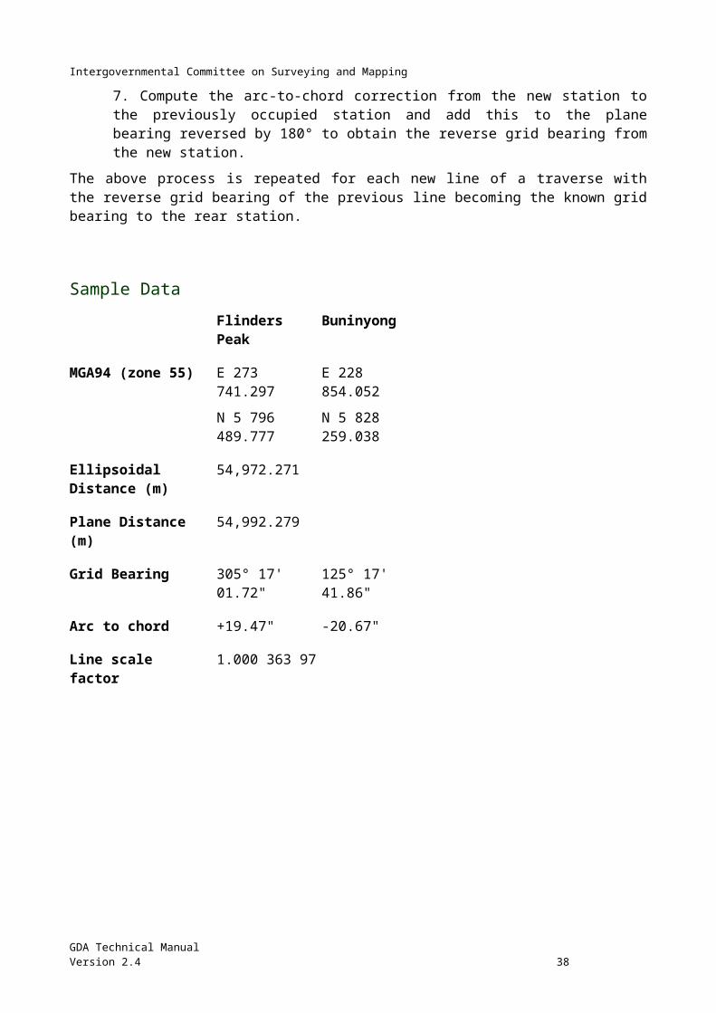
Intergovernmental Committee on Surveying and Mapping
Formulae
e2=2 f −f 2
ν=a /(1−e2sin2 Φ)1/ 2
ρ=a (1−e2 )/ (1−e2 sin2 Φ )3 /2
ΔΦ (rad )={(−ΔX sin Φcos λ−ΔY sin Φsin λ+ ΔZ cosΦ+(aΔf + fΔa )sin 2 Φ) /ρ }
ΔΦ=206264.8062 Δ
ΦGDA 94=Φ AGD+ΔΦ
Δλ (rad )= {(−ΔX sin λ+ ΔY cos λ ) / (ν cosΦ ) }
Δλ =206264.8062 Δ
λGDA 94=λ AGD+ Δλ
Δh=ΔX cosΦcos λ+ΔY cosΦ sin λ+ΔZ sin Φ+ (aΔf + fΔa ) sin2Φ−Δa
hANS=H+N ANS
hGDA 94=hANS+ Δh
Examples
AGD66 GDA94
Latitude -37° 39’ 15.56" -37° 39’ 10.18"
Longitude 143° 55’ 30.63 143° 55’ 35.43"
Ellipsoidal height 750 m 749 m
AGD84 GDA94
Latitude -37° 39’ 15.56" -37° 39’ 10.17"
Longitude 143° 55’ 30.55" 143° 55’ 35.38"
Ellipsoidal height 750 m 748 m
GDA Technical ManualVersion 2.4 40
Intergovernmental Committee on Surveying and Mapping
Simple Block Shift Excel Spreadsheet – Block Shifts Between AGD66, AGD84 & GDA94
A basic method of transforming by adding an average block shift in position determined from one or more common points. The accuracy of this transformation method is entirely dependent on the accuracy of the common point coordinates and the area over which the shift is to be averaged.
The average size of the block shifts between AGD66, AGD84 and GDA94 has been computed for 1:250,000 topographic map areas across Australia. These block shifts have a limited accuracy of about 10 m.
Comparison of Transformation Methods The grid transformation is the recommended and most accurate method of transformation in Australia. Ideally no other method should be needed, but it is recognised that there are different user requirements, so less accurate transformation methods are also provided.
Comparison of transformation by various methods The table below shows a sample of points that have been transformed from both AGD66 and AGD84 to GDA94 by the methods explained in this Chapter 7.
The 7 parameter (Similarity) transformation uses the appropriate national transformation parameters (AGD66 or AGD84). Similarly, the Molodensky transformation uses the AGD66 or AGD84 parameters as appropriate. The Grid Transformation uses the appropriate national grid (AGD66 or AGD84).
GDA Technical ManualVersion 2.4 41
Figure 7-11: Magnitude of Block Shift vector, in metres, between ADG66 and ADG84
Intergovernmental Committee on Surveying and Mapping
Table 7-18: Example transformation points from both AGD66 and AGD84 to GDA94 by various transformation methods
GDA Transformed
Known AGD84 Known GDA94
GDA94 (Block Shift)
GDA94 (Molodensky)
GDA94 (Similarity)
GDA94 (National
NTv2 Grid)
DerivedGDA94 Ellip.
Ht. (AUSGeoid09)
Latitude -29° 02' 52.0825"
47.6169" 47.64" 47.60" 47.602" 47.6175"
Longitude 115° 20' 43.9092"
49.1004" 49.12" 49.04" 49.087" 49.1010"
Ellip. Ht. (m) 284.998 241.291 240 242.46 241.329
N value (m) 18.5 -25.169
AHD (m) 266.498
Latitude -20° 58’ 57.9705"
53.1700" 53.15" 53.17" 53.181" 53.1667"
Longitude 117° 05' 45.0683"
49.8726" 49.87" 49.86" 49.887" 49.8708"
Ellip. Ht. (m) 129.902 109.246 108 109.05 109.191
N value (m) 14 -6.711
AHD (m) 115.902
Latitude -19° 20' 56.0013"
50.4284" 50.44" 50.44” 50.432” 50.4303"
Longitude 146° 46' 26.8165"
30.7906" 30.81" 30.75" 30.780" 30.7918"
Ellip. Ht. (m) 541.709 587.077 588 583.64 587.152
N value (m) 13 58.443
AHD (m) 528.709
Latitude -10° 35’ 07.9983"
2.6077" 2.65" 2.67" 2.642" 2.6113"
Longitude 142° 12' 35.5265"
39.5762" 39.54" 39.49" 39.524" 39.5716"
GDA Technical ManualVersion 2.4 42
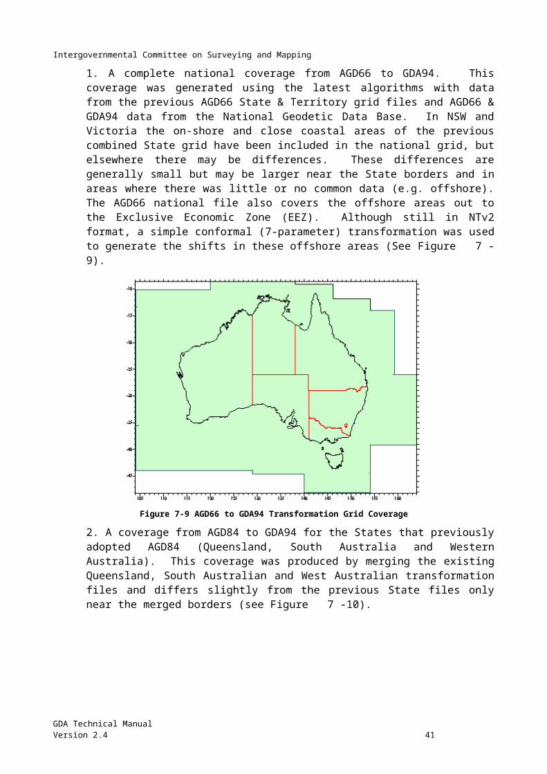
Intergovernmental Committee on Surveying and Mapping
Ellip. Ht. (m) 73.344 130.0452 136 129.99 130.176
N value (m) 14.6 71.432
AHD (m) 58.744
Latitude -37° 23' 57.3212"
52.0181" 52.06" 52.05" 52.039" 52.0188"
Longitude 140° 40' 45.4673"
50.4482" 50.47" 50.45" 50.440" 50.4497"
Ellip. Ht. (m) 88.934 72.12 71 72.43 71.968
N value (m) 14.106 -2.860
AHD (m) 74.828
Latitude -25° 42' 30.4392"
25.5493" 25.59" 25.58" 25.577" 25.5493"
Longitude 122° 54' 29.7110"
34.6508" 34.64" 34.61" 34.640" 34.6509"
Ellip. Ht. (m) 499.691 480.2142 479 479.68 480.489
N value (m) 10.79 -8.412
AHD (m) 488.901
Latitude -17 31' 45.2316"
40.0554" 40.08" 40.08" 40.070" 40.0734"
Longitude 128° 47' 56.4545"
0.98617" 00.99" 00.98" 00.988" 00.9781"
Ellip. Ht. (m) 246.139 258.81 260 258.04 259.827
N value (m) 16.091 29.779
AHD (m) 230.048
Table 7-19: Example transformation points from both AGD66 and AGD84 to GDA94 by various transformation methods
GDA Transformed
GDA Technical ManualVersion 2.4 43
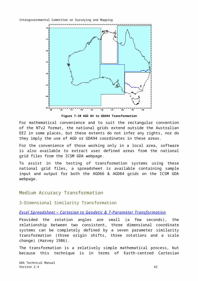
Intergovernmental Committee on Surveying and Mapping
Known AGD66 Known GDA94
GDA94 (Block Shift)
GDA94 (Molodensky
)
GDA94 (Similarity)
GDA94 (National
NTv2 Grid)
GDA94 Ellip. Ht. (AUSGeoid09)
Latitude -42° 48'
22.3726"
16.9851"
16.93" 16.97" 16.963" 16.9846"
Longitude 147°
26'
14.5257"
19.4355"
19.41" 19.49" 19.448" 19.4333"
Ellip Ht (m) 64.76 41.126 42 44.45 41.139
N value (m) 20 -3.617
AHD (m) 44.756
Latitude -18° 01'
37.8335"
32.7834"
32.77" 32.65" 32.659" 32.7833"
Longitude 130°
39'
17.9193"
22.3169”
22.34" 22.37" 22.379" 22.3174"
Ellip Ht (m) 348.195 363.34 365 362.43 364.088
N value (m) 17.225 33.118
AHD (m) 330.970
Latitude -37° 57'
9.1288" 3.7203" 3.71" 3.73" 3.734" 3.7207"
Longitude 144°
25'
24.7866"
29.5244"
29.467" 29.57" 29.555" 29.5258"
Ellip Ht (m) 364.2 350.948 354 352.25 350.742
N value (m) 17 3.542
AHD (m) 347.2
Latitude -37° 39'
15.5571"
10.1561"
10.81" 10.81" 10.176" 10.1563"
Longitude 143°
55'
30.6330"
35.3839"
35.39" 35.43" 35.409" 35.3834"
Ellip Ht (m) 761.986 749.855 749 750.05 749.627
N value (m) 17 4.641
GDA Technical ManualVersion 2.4 44
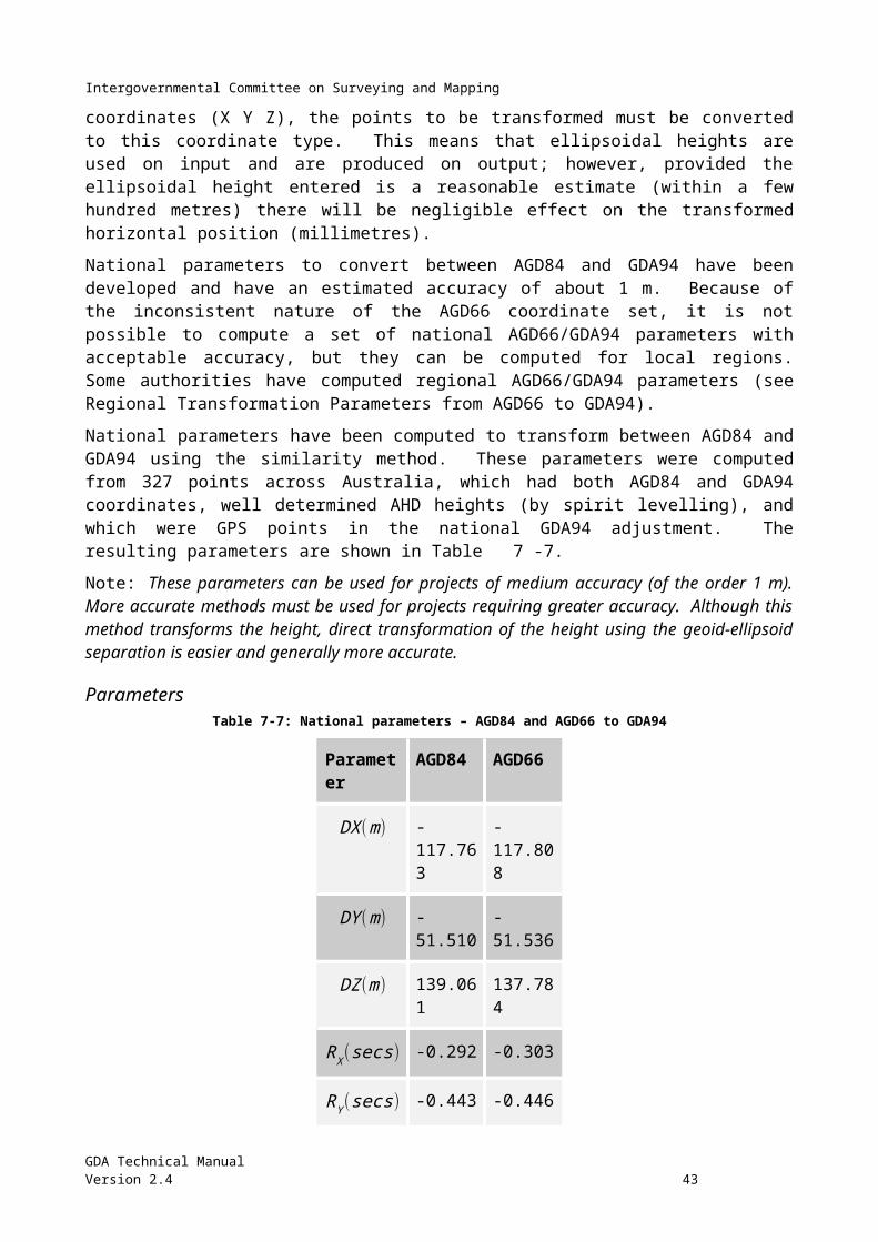
Intergovernmental Committee on Surveying and Mapping
AHD (m) 744.986
GDA Technical ManualVersion 2.4 45
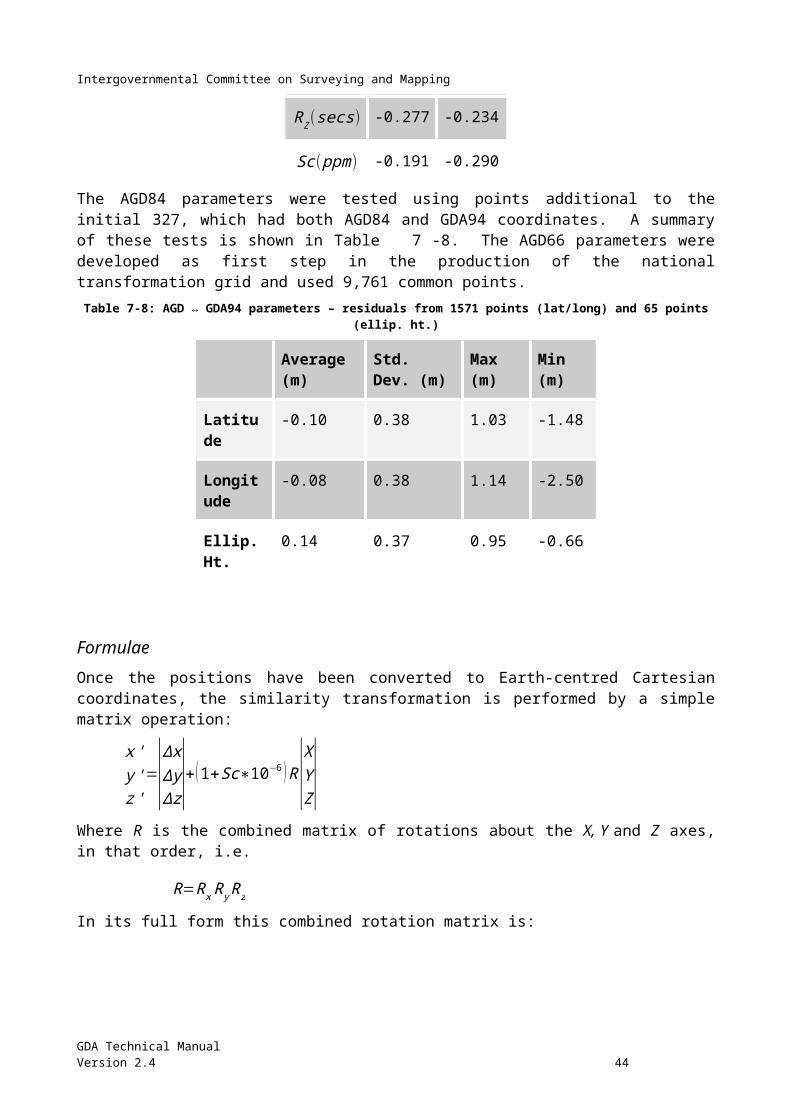
Intergovernmental Committee on Surveying and Mapping
Figure 7-12: Comparison of transformation methods for latitude, longitude and height.
GDA Technical ManualVersion 2.4 46
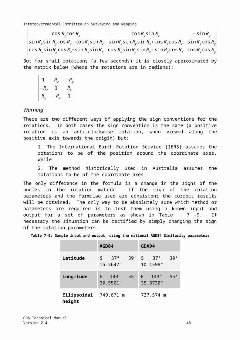
Intergovernmental Committee on Surveying and Mapping
Chapter 8 The Australian Height Datum (AHD) The Australian Height Datum (AHD) is the official height datum for Australia.
Background On 5 May 1971 the then Division of National Mapping, on behalf of the National Mapping Council of Australia, carried out a simultaneous adjustment of 97,230 kilometres of two-way levelling. Mean sea level for 1966-1968 was assigned the value of zero on the Australian Height Datum at thirty tide gauges around the coast of the Australian continent.
The resulting datum surface, with minor modifications in two metropolitan areas, has been termed the Australian Height Datum (AHD) and was adopted by the National Mapping Council at its twenty-ninth meeting in May 1971 as the datum to which all vertical control for mapping is to be referred. The datum surface is that which passes through mean sea level (1966-1968) at the thirty tide gauges and through points at zero AHD height vertically below the junction points of the Basic Levelling (see below).
The determination of the AHD was documented in Division of National Mapping Technical Report No. 12 (Roelse, Granger et al. 1971).
Basic and Supplementary Levelling Two-way levelling of third order accuracy or better, used in the original adjustment of 5 May 1971 which formed the AHD, is called "Basic levelling". Levelling subsequently adjusted to the AHD is called "Supplementary levelling".
Tasmania The levelling network in Tasmania was adjusted on 17 October 1983 to re-establish heights on the Australian Height Datum (Tasmania). This network, which consists of seventy-two sections between fifty-seven junction points is based on mean sea level for 1972 at the tide gauges at Hobart and Burnie. Mean sea level at both Hobart and Burnie was assigned the value of zero on the AHD (Tasmania).
Islands If the levels on islands closely adjacent to the Australian mainland are observed to standard third order accuracy, and are referred to mean sea level at a satisfactory tide gauge, they are deemed to be part of the Australian Height Datum.
AHD, Mean Sea Level and the Geoid The AHD is an imperfect realisation of mean sea level because some of the tide gauges used for its definition were not in ideal locations; the mean sea level determination was for a limited period of time and no allowance was made for sea surface topography. The difference between AHD and mean sea level, which may be of the order of several decimetres (Mitchell 1990), is not significant for
GDA Technical ManualVersion 2.4 47
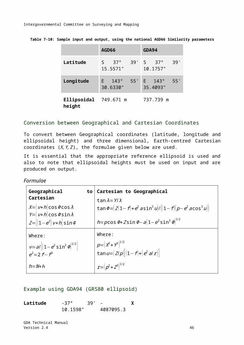
Intergovernmental Committee on Surveying and Mapping
conventional propagation of AHD, which is relative to existing AHD bench marks, but may be important if connecting AHD to a recent determination of mean sea level.
Although the geoid is often equated to mean sea level, it may actually differ from it by the order of a metre, largely due to sea surface topography (Bomford 1980).
With improvements in geoid models and GNSS heighting, the difference between these three surfaces is sometimes apparent, particularly over large areas, or in areas where there are rapid changes in the slope of the geoid.
GDA Technical ManualVersion 2.4 48
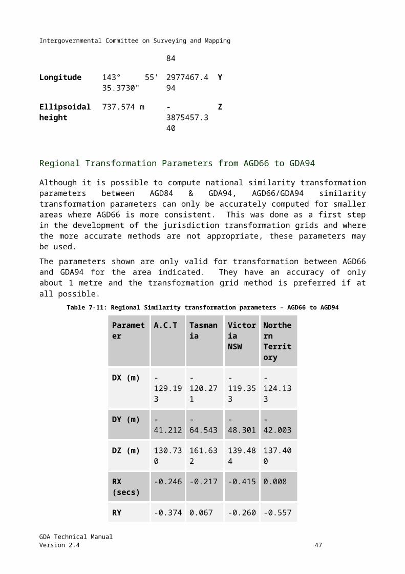
Intergovernmental Committee on Surveying and Mapping
Chapter 9 The Australian National Geoid The geoid is a surface of equal gravitational potential that is approximated by mean sea level. The height of the ellipsoid and the geoid can differ by tens of metres across the Australian mainland with the difference known as the geoid-ellipsoid separation (N value). Geoid – ellipsoid separation values can be used to reduce observed GNSS ellipsoidal heights (h) to heights relative to approximate Mean Sea Level (MSL).
AUSGeoid09AUSGeoid09 is the latest in a series of national geoid models for Australia which provides the capability to convert from GNSS ellipsoidal heights to approximate AHD heights. These are known as derived AHD heights. AUSGeoid09 is a 1' by 1' grid (approximately 1.8 km) of AHD – ellipsoid separation (NAHD) values. These NAHD values have an estimated uncertainty of ±0.06 m at the 95% confidence interval (Brown et al. 2011). In most cases, AUSGeoid09 provides a relative uncertainty comparable to [12 mm∗√k ]where k is distance in km for relative height transfer.
GDA Technical ManualVersion 2.4 49
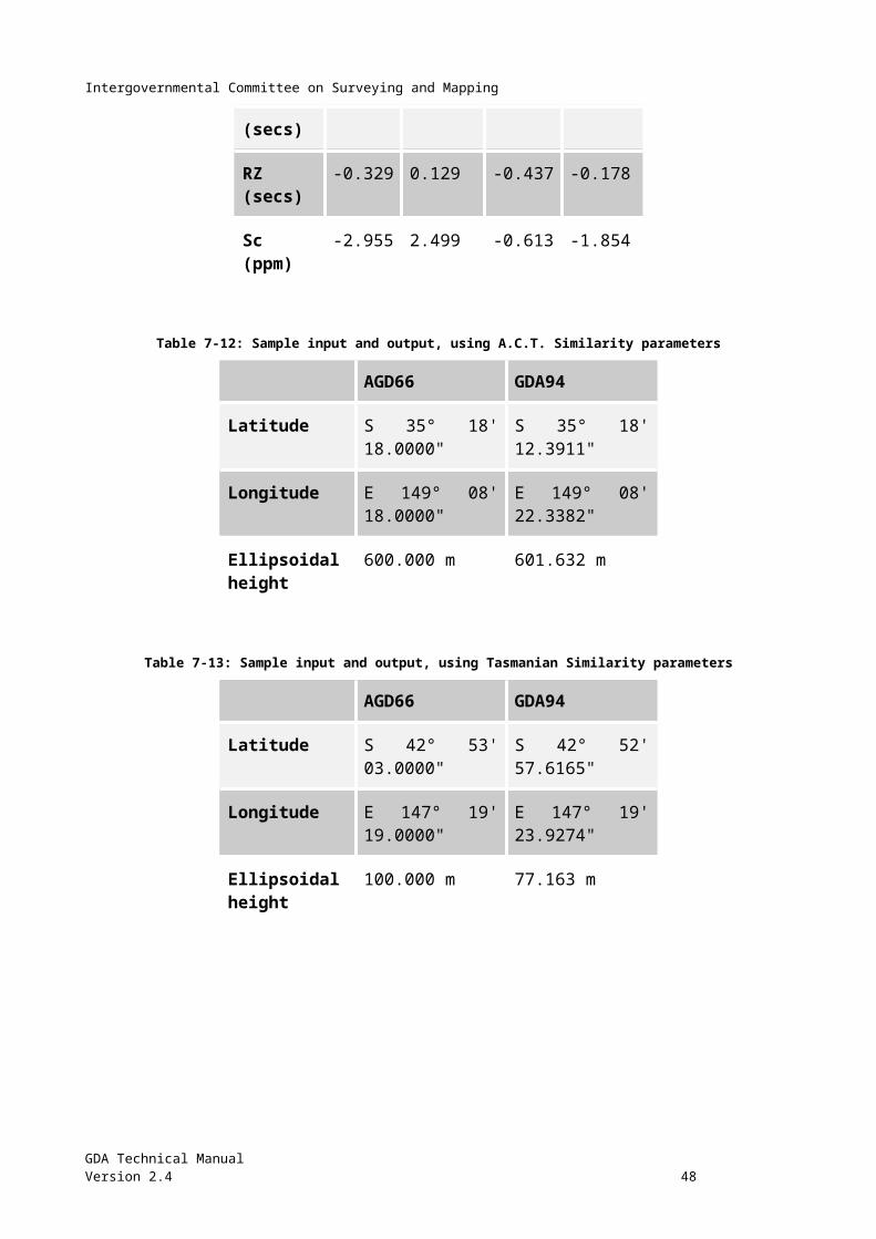
Intergovernmental Committee on Surveying and Mapping
Figure 9-13: Relationship between the ellipsoid, gravimetric geoid, AUSGeoid, and the topography.
H AHD=h−N AHD
where:
H A HD = derived AHD heighth = ellipsoid heightN AHD = AUSGeoid09 value
In places where collocated AHD and GNSS data were not used in the development of AUSGeoid09, discrepancies between the derived AHD value and the published AHD value (from a jurisdictional database) can occur. The cause of these discrepancies includes uncertainty in the observed ellipsoidal height and local / regional deformation since the time of the AHD levelling.
Prior to AUSGeoid09, the AUSGeoid models were largely gravimetric geoid models, and sea surface topography effects caused errors of up to ±0.5 m between derived and published AHD heights. Given that this error was predominantly caused by a 1 m trend from south-west to north-east Australia, these discrepancies between the derived AHD value and published AHD values were minimised by applying the N values differentially, rather than in an absolute sense. AUSGeoid09 provides a more direct and more accurate model for converting ellipsoidal heights to derived AHD heights by incorporating a geometric component which models the offset between the gravimetric geoid and AHD.
AUSGeoid09 data files and interpolation software and further information can be obtained from Geoscience Aust ralia's web site .
AUSGeoid09 Technical SpecificationsAUSGeoid09 is a gravimetric – geometric quasigeoid. The gravimetric component (Featherstone et al. 2011) was developed using:
degree-2160 spherical harmonic expansion of the EGM2008 global gravity model (Pavlis, Holmes et al. 2008)
approximately 1.4 million land gravity anomalies from the Australian national gravity database the 9” x 9” GEODATA-DEM9S digital elevation model of Australia, and altimeter-derived marine gravity anomalies from the DNSC2008GRA grid (Andersen, Knudsen
et al. 2010)
The geometric component (Brown et al. 2011) was developed using two datasets:
The primary dataset of 2638 co-located GNSS-AHD heights provided by the State and Territory surveying authorities.
A secondary dataset of 4233 Australian National Levelling Network Junction Points to provide a higher-resolution definition of the offset between the AHD and gravimetric quasigeoid.
GDA Technical ManualVersion 2.4 50
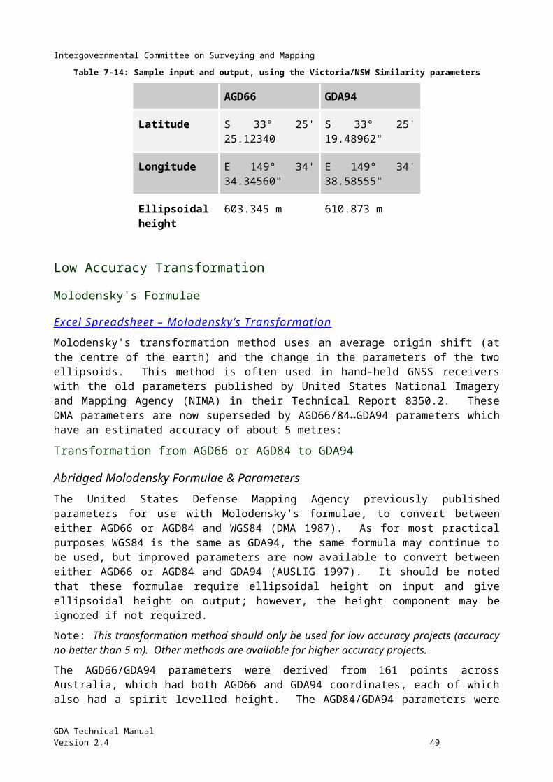
Intergovernmental Committee on Surveying and Mapping
Chapter 10 Test Data GDA94 and MGA94 (zone 55) values
Buninyong Flinders Peak
Latitude (Φ) S 37° 39' 10.15611" S 37° 57' 03.72030"
Longitude (λ) E 143° 55' 35.38393" E 144° 25' 29.52442"
AHD (H) 744.986 m 347.200 m
NAUSGeoid09 4.641 3.542
Ellipsoidal height (h) 749.855 m 350.948 m
Easting 228,854.052 273,741.297
Northing 5,828,259.038 5,796,489.777
X -4,087,103.458 -4,096,088.424
Y 2,977,473.0435 2,929,823.0843
Z -3,875,464.7525 -3,901,375.4540
Azimuth (α) 127° 10' 25.07” 306° 52' 05.37"
Grid convergence (γ) -01° 52' 43.22" -01° 35' 03.65"
Grid bearing (β) 125° 17' 41.86" 305° 17' 01.72"
Arc to chord (δ) -20.67" +19.47"
Plane bearing (θ) 125° 17' 21.18" 305° 17' 21.18"
Point scale factor (k) 1.000 50567 1.000 23056
Meridian distance (m) -4,173,410.326 -4,205,192.300
Rho (ρ) 6359253.8294 6359576.5731
Nu (ν) 6386118.6742 6386226.7080
Ellipsoidal distance (s) 54,972.271
Line scale factor (K) 1.000 36397
Grid (& plane) distance (L) 54,992.279
Meridian convergence 18' 19.70"
GDA Technical ManualVersion 2.4 51
Intergovernmental Committee on Surveying and Mapping
(∆α)
Line curvature (∆β) 40.14"
GDA Technical ManualVersion 2.4 52
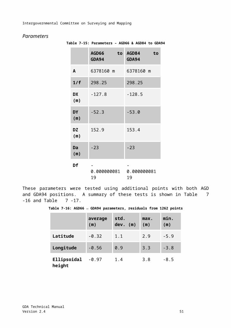
Intergovernmental Committee on Surveying and Mapping
Traverse Diagram
GDA Technical ManualVersion 2.4 53
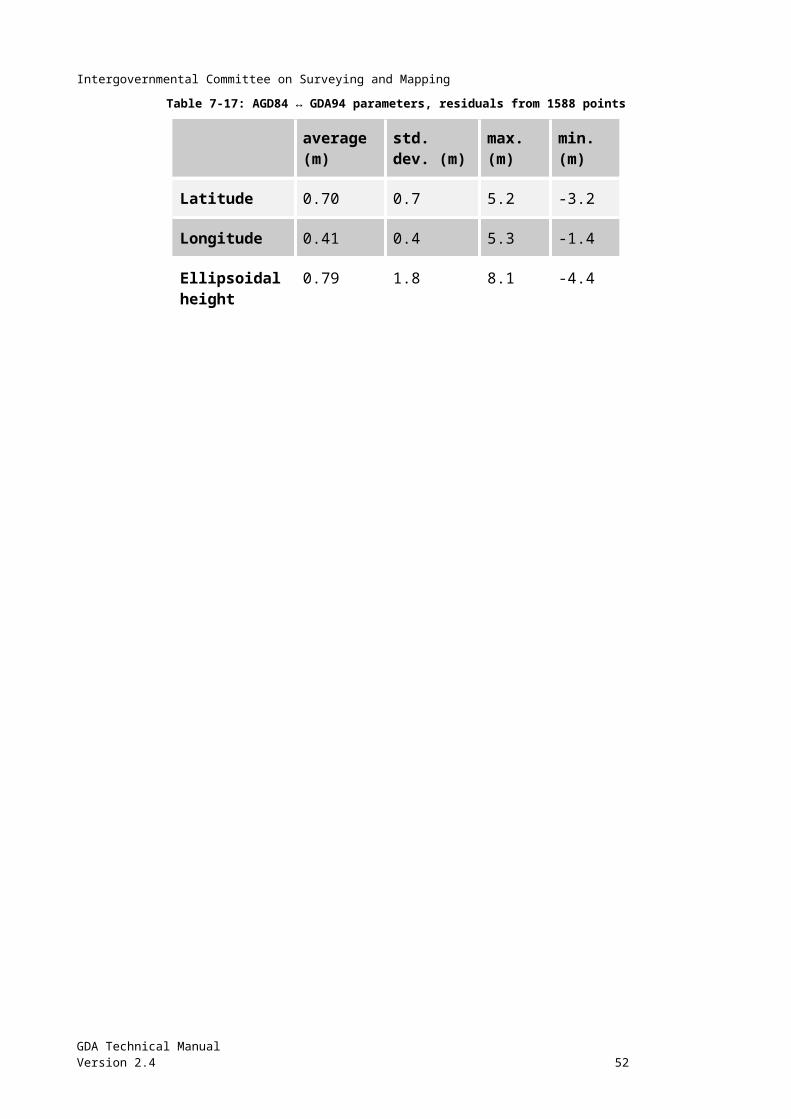
Intergovernmental Committee on Surveying and Mapping
Bibliography A.H.Q. (1942). Tables for the Computation of Geographic Positions and Rectangular Coordinates (Tranverse Mercator projection) - based on Clarke 1858 figure. Compiled by A.H.Q Survey Coy, by the Authority of Director of Survey.
Andersen, O., P. Knudsen, et al. (2010). "The DNSC08GRA global marine gravity field from double retracked satellite altimetry." Journal of Geodesy 84(3): 191-199.
AUSLIG (1997). Internal Report to ICSM, Australian Land Information Group.
Bomford, A. G. (1967). "THE GEODETIC ADJUSTMENT OF AUSTRALIA, 1963–1966." Survey Review 19(144): 52-71.
Bomford, G. (1980). Geodesy (4th edn) Oxford, Clarendon Press.
Boucher, C., Z. Altamimi, et al. (1993). ITRF 92 and its associated velocity field. IERS Technical Note 15. Paris, Central Bureau of IERS - Observatoire de Paris: 164.
Brown, N. J., W. Featherstone, et al. (2011). "AUSGeoid09: a more direct and more accurate model for converting ellipsoidal heights to AHD heights." Journal of Spatial Science 56(1): 27-37.
Clark, D. (1966). Plane and Geodetic Surveying. London, England, Constable and Company, Ltd.
Collier, P. A., V. S. Argeseanu, et al. (1998). "Distortion Modelling and the Transition to GDA94." Australian Surveyor 43(1): 29-40.
Collier, P. A. and J. Steed (2001). Australia's National GDA94 Transformation Grids. 42nd Australian Surveyors Congress, Brisbane, Australia.
Dawson, J. and A. Woods (2010). "ITRF to GDA94 coordination transformations." Journal of Applied Geodesy 4: 189-199.
DMA (1987). Department of Defense World Geodetic System 1984, its definition and relationships with local geodetic systems. DMA Technical report 8350.2 Defense Mapping Authority.
Featherstone, W., J. Kirby, et al. (2011). "The AUSGeoid09 model of the Australian Height Datum." Journal of Geodesy 85(3): 133-150.
Grossmann, W. (1964). Geodetic calculations and illustrations in the National Survey (Geodetische Rechnungen und Abbildungen). Wittwer-Verlag, Stuttgart.
Harvey, B. R. (1986). "Transformations of 3D Coordinates." The Australian Surveyor 33(2): 105-125.
Jordan, W. and O. Eggert (1941). Handbuch der Vermessungskunde.
Lines, J. D. (1992). Australia on Paper, The story of Australian mapping. Box Hill, Victoria, Fortune Publications.
Malys, S. and J. Slater (1994). Maintenance and Enhancement of the World Geodetic System 1984. Proceedings of the 7th International Technical Meeting of the Satellite Division of The Institute of Navigation (ION GPS 1994), Salt Lake City, UT.
Malys, S., J. Slater, et al. (1997). Refinements to The World Geodetic System 1984. Proceedings of the 10th International Technical Meeting of the Satellite Division of The Institute of Navigation (ION GPS 1997), Kansas City, MO.
Mitchell, H. L. (1990). GPS Heighting and the AHD, Report of the GPS Heighting Study Group of the Australian GPS Users Group, Institution of Surveyors, Australia.
GDA Technical ManualVersion 2.4 54
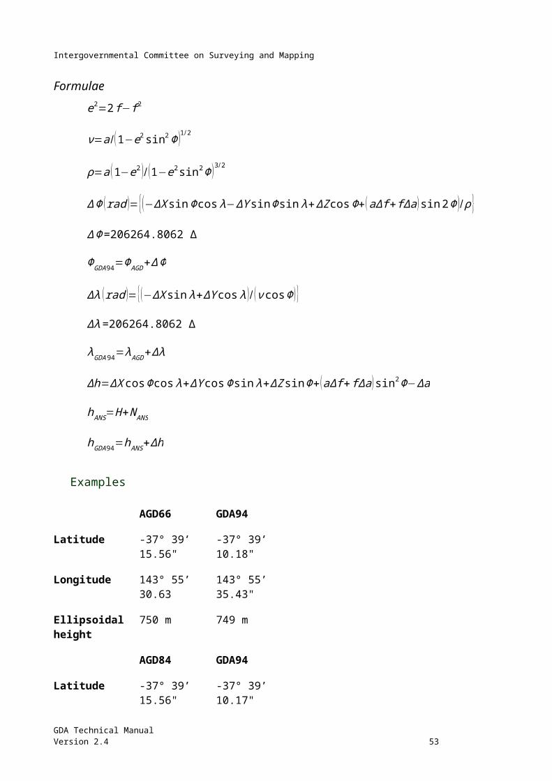
Intergovernmental Committee on Surveying and Mapping
Morgan, P. J., Y. Bock, et al. (1996). A Zero Order GPS Network for the Australian Region. UniServ Report S-46, University of NSW, School of Geomatic Engineering.
NGA (2014). Department of Defense World Geodetic System 1984 - Its Definition and Relationships with Local Geodetic Systems, NGA.STND.0036_1.0.0_WGS84, Version 1.0.0, National Geospatial-Intelligence Agency, Arnold, MO. Available at: http://earth-info.nga.mil/GandG/publications/NGA_STND_0036_1_0_0_WGS84/NGA.STND.0036_1.0.0_WGS84.pdf
NIMA (2004). Department of Defense World Geodetic System 1984 -- Its Definition and Relationships with Local Geodetic Systems. NIMA Technical Report 8350.2 3rd release, National Imagery and Mapping Agency, St. Louis, MO.
NMCA (1976). Report on work complete during period 1945-1975, National Mapping Council of Australia, Australian Division of National Mapping.
NMCA (1986). The Australian Geodetic Datum Technical Manual. Canberra, National Mapping Council Special Publication 10.
Pavlis, N. K., S. A. Holmes, et al. (2008). An Earth Gravitational Model to Degree 2160: EGM2008. European General Assembly 2008. Vienna, Austria.
Rainsford, H. F. (1955). "Long Geodesics on the Ellipsoid." Bulletin géodésique 37.
Redfearn, J. C. B. (1948). "Transverse Mercator Formulae." Empire Survey Review 69.
Roelse, A., H. W. Granger, et al. (1971). The adjustment of the Australian levelling survey 1970-1971. National Mapping Technical Report No. 12, 2nd edition. Canberra, Department of National Development.
Seeber, G. (1993). Satellite Geodesy. New York, de Gruyter.
Snyder, J. P. (1984). Map projections used by the U.S. Geological Survey. U.S. Geological Survey Bulletin 1532, 2nd Edition United States of America Department of Interior.
Sodano, E. M. (1965). "General non-iterative solution of the inverse and direct geodetic problems." Bulletin géodésique 75(1): 69-89.
Steed, J. B. (1990). "A practical approach to transformation between commonly used reference systems." Australian Surveyor 35(3): 248-264.
Swift, E. (1994). Improved WGS84 coordinates for the DMA and Air Force GPS tracking sites. Proceedings of the 7th International Technical Meeting of the Satellite Division of The Institute of Navigation (ION GPS 1994), Salt Lake City, UT.
Vincenty, T. (1975). Direct and inverse solutions of geodesics on the ellipsoid with application of nested equations, Survey Review XXII. 176.
GDA Technical ManualVersion 2.4 55
Intergovernmental Committee on Surveying and Mapping
Diagrams
MGA cross section
Latitude Longitude
GDA Technical ManualVersion 2.4 56
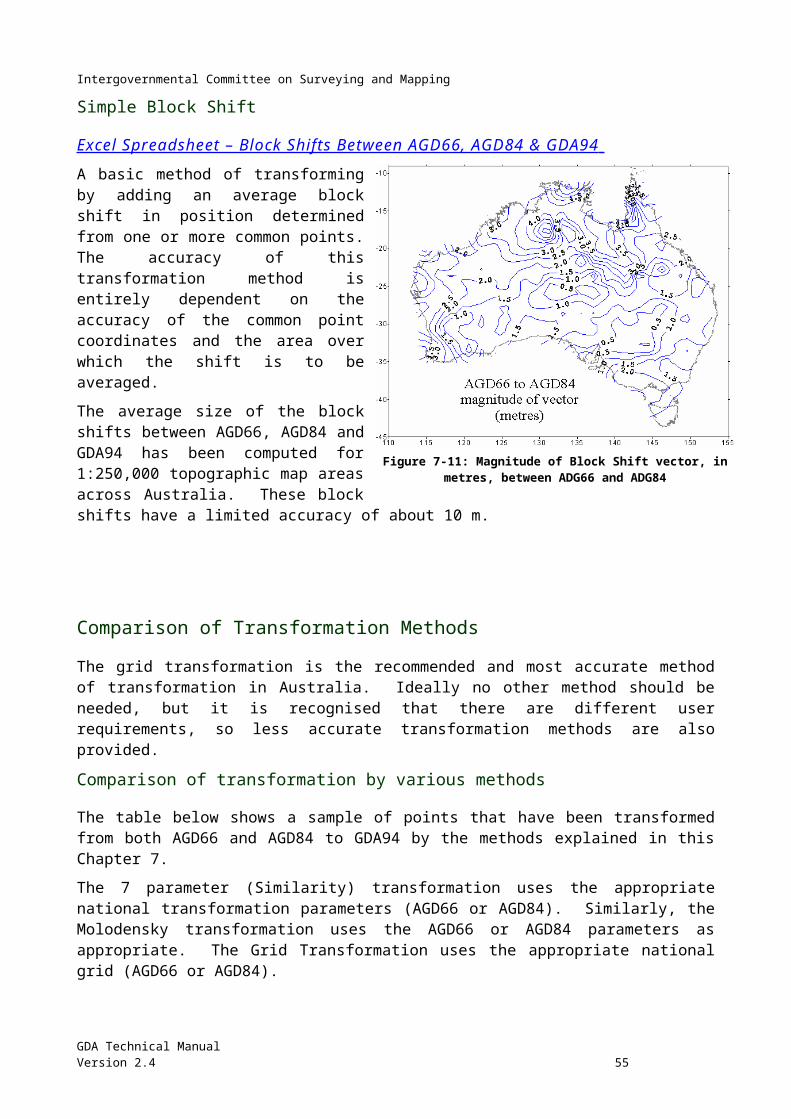
Intergovernmental Committee on Surveying and Mapping
Semi-major and Semi-Minor axis
UTM Projection
GDA Technical Manual 57Version 2.4
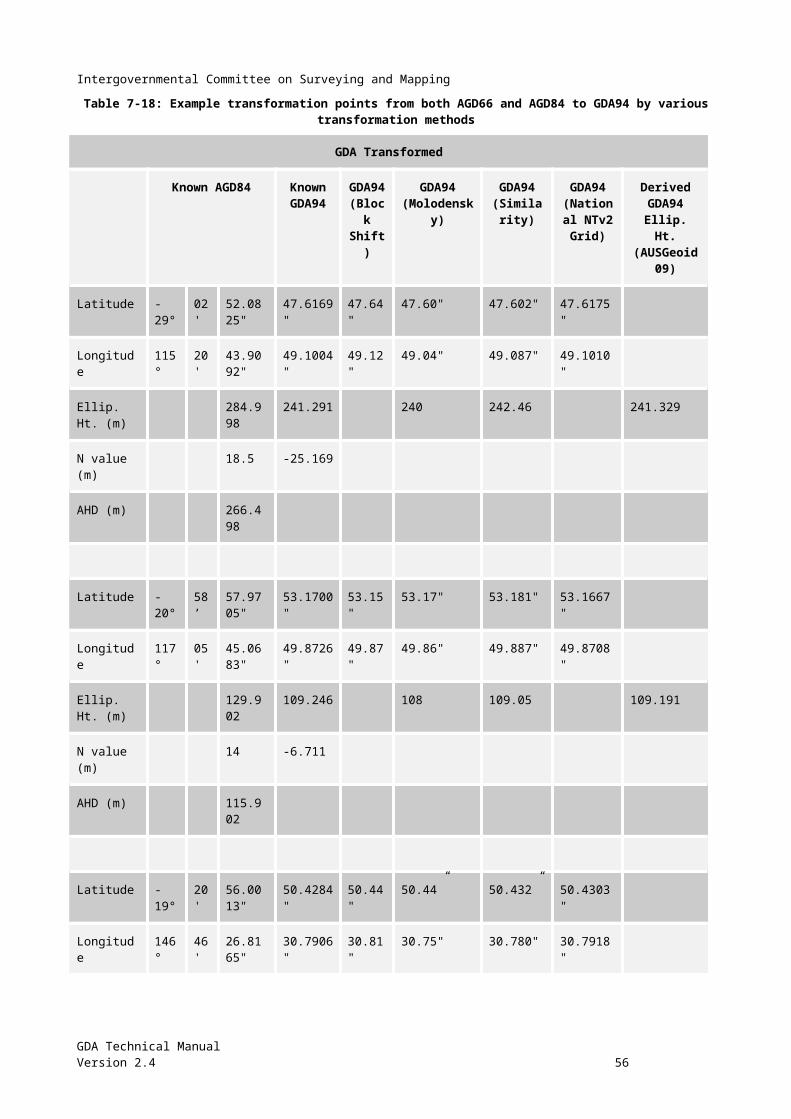
Intergovernmental Committee on Surveying and Mapping
Greek Alphabet
Alpha Α αBeta Β βGamma Γ γDelta Δ δEpsilon Ε εZeta Ζ ζEta Η ηTheta Θ θIota Ι ιKappa Κ κLambda Λ λMu Μ μNu Ν νXi Ξ ξOmicron Ο οPi Π πRho Ρ ρSigma Σ σTau Τ τUpsilon Υ υPhi Φ φChi Χ χPsi Ψ ψOmega Ω ωGDA Technical Manual 58Version 2.4
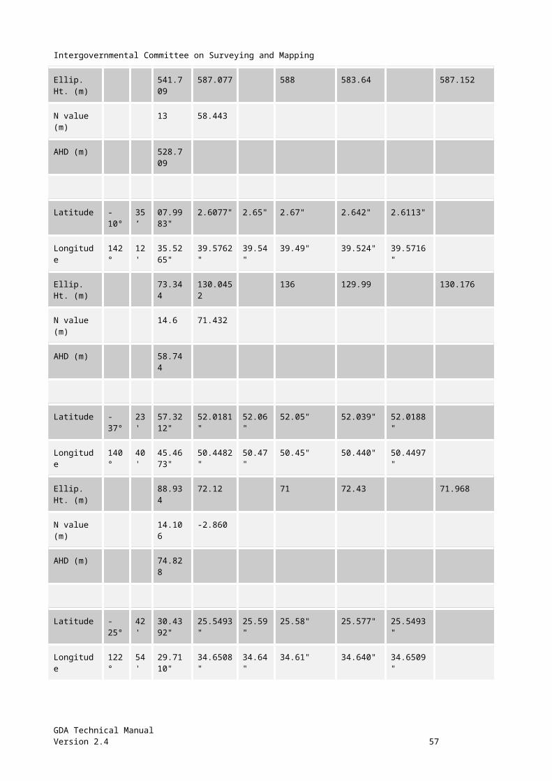
Intergovernmental Committee on Surveying and Mapping
GDA Technical Manual 59Version 2.4