Embed Size (px)
DESCRIPTION
fgng
Citation preview
Selection of Forging EquipmentTaylan Altan and Manas Shirgaokar, The Ohio State University
DEVELOPMENTS in the forging industry aregreatly influenced by the worldwide require-ments for manufacturing ever larger, more pre-cise, and more complex components from moredifficult-to-forge materials. The increase indemand for stationary power systems, jetengines, and aircraft components as well as theever-increasing foreign technological competi-tion demand cost reduction in addition to con-tinuous upgrading of technology. Thus, the moreefficient use of existing forging equipment andthe installation of more sophisticated machineryhave become unavoidable necessities. Forgingequipment influences the forging processbecause it affects deformation rate, forgingtemperature, and rate of production. Develop-ment in all areas of forging has the objectives of(a) increasing the production rate, (b) improvingforging tolerances, (c) reducing costs by mini-mizing scrap losses, by reducing preformingsteps, and by increasing tool life, and (d)expanding capacity to forge larger and moreintricate and precise parts. Forging equipmentgreatly affects all these aforementioned factors.
The purchase of new forging equipmentrequires a thorough understanding of the effectof equipment characteristics on the forgingoperations, load and energy requirements of thespecific forging operation, and the capabilitiesand characteristics of the specific forgingmachine to be used for that operation. Increasedknowledge of forging equipment would alsospecifically contribute to:
� More efficient and economical use of existingequipment
� More exact definition of the existing max-imum plant capacity
� Better communication between the equip-ment user and the equipment builder
� Development of more advanced processessuch as precision forging of gears and of tur-bine and compressor blades
This section details the significant factorsin the selection of forging equipment for a par-ticular process. The article “Hammers andPresses for Forging” in this Volume containsinformation on the principles of operation andthe capacities of various types of forgingmachines.
Process Requirements andForging Machines
The behavior and characteristics of the form-ing machine influence:
� The flow stress and workability of thedeforming material
� The temperatures in the material and in thetools, especially in hot forming
� The load and energy requirements for a givenproduct geometry and material
� The “as-formed” tolerances of the parts� The production rate
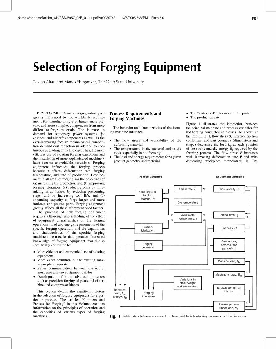
Figure 1 illustrates the interaction betweenthe principal machine and process variables forhot forging conducted in presses. As shown atthe left in Fig. 1, flow stress �ss, interface frictionconditions, and part geometry (dimensions andshape) determine the load Lp at each positionof the stroke and the energy Ep required by theforming process. The flow stress �ss increaseswith increasing deformation rate _�ee�ee and withdecreasing workpiece temperature, h. The
Process variables
Strain rate, ε
Die temperature
Work metaltemperature, θ
Flow stress offorging
material, σ
Friction,lubrication
Forginggeometry
Requiredload, Lp
Energy, Ep
Forgingtolerances
Variations instock weight
and temperature
Slide velocity, Vp
Contact time, tp
Stiffness, C
Clearances,flatness, andparallelism
Machine load, LM
Machine energy, EM
Strokes per min atidle, n0
Strokes per minunder load, np
Equipment variables
Fig. 1 Relationships between process and machine variables in hot-forging processes conducted in presses
Name ///sr-nova/Dclabs_wip/ASM/6957_02B_01-11.pdf/A0003974/ 13/5/2005 5:32PM Plate # 0 pg 1
magnitudes of these variations depend on thespecific work material (see the Sections on for-ging of specific metals and alloys in thisVolume). The frictional conditions deterioratewith increasing die chilling.
As indicated by the lines connected to the“Work metal temperature” block in Fig. 1, fora given initial stock temperature, the tem-perature variations in the part are largelyinfluenced by (a) the surface area of contactbetween the dies and the part, (b) the partthickness or volume, (c) the die temperature,(d) the amount of heat generated by deforma-tion and friction, and (e) the contact time underpressure tp.
The velocity of the slide under pressure Vp
determines mainly tp and the deformation rate_�ee�ee. The number of strokes per minute under no-load conditions n0, the machine energy EM,and the deformation energy Ep required by theprocess influence the slide velocity under loadVp and the number of strokes under load np; np
determines the maximum number of partsformed per minute (the production rate) if thefeed and unloading of the machine can becarried out at that speed. The relationshipsillustrated in Fig. 1 apply directly to hot for-ging in hydraulic, mechanical, and screwpresses.
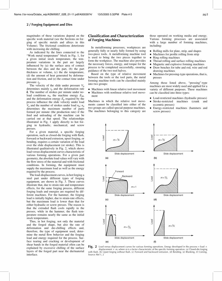
For a given material, a specific forgingoperation, such as closed-die forging with flash,forward or backward extrusion, upset forging, orbending, requires a certain variation of the loadover the slide displacement (or stroke). This isillustrated qualitatively in Fig. 2, which showsload versus displacement curves characteristic ofvarious forming operations. For a given partgeometry, the absolute load values will vary withthe flow stress of the material and with frictionalconditions. In forming, the equipment mustsupply the maximum load as well as the energyrequired by the process.
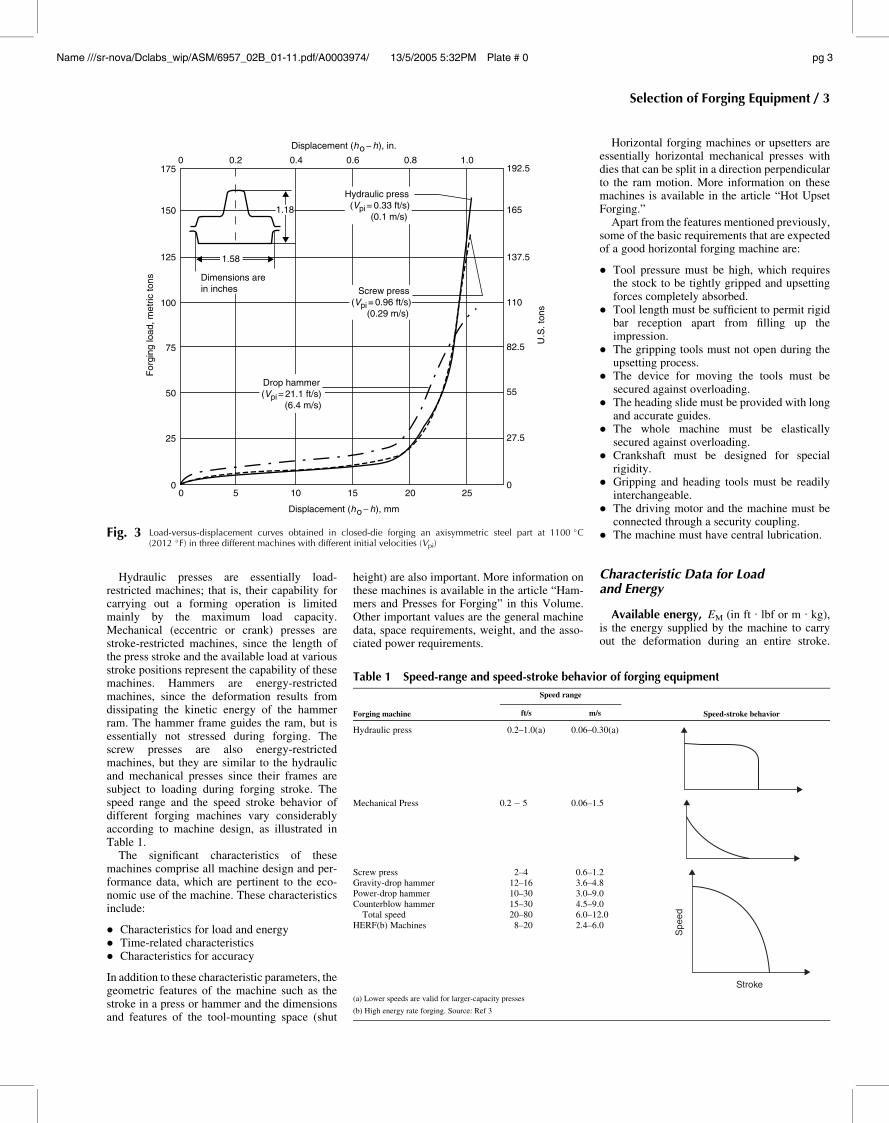
The load-displacement curves, in hot forging asteel part under different types of forgingequipment, are shown in Fig. 3. These curvesillustrate that, due to strain rate and temperatureeffects, for the same forging process, differentforging loads and energies are required by dif-ferent machines. For the hammer, the forgingload is initially higher, due to strain-rate effects,but the maximum load is lower than that foreither hydraulic or screw presses. The reason isthat the extruded flash cools rapidly in thepresses, while in the hammer, the flash tem-perature remains nearly the same as the initialstock temperature.
Thus, in hot forging, not only the materialand the forged shape, but also the rate ofdeformation and die-chilling effects and,therefore, the type of equipment used, deter-mine the metal flow behavior and the forgingload and energy required for the process. Sur-face tearing and cracking or development ofshear bands in the forged material often can beexplained by excessive chilling of the surfacelayers of the forged part near the die/materialinterface.
Classification and Characterizationof Forging Machines
In metalforming processes, workpieces aregenerally fully or nearly fully formed by usingtwo-piece tools. A metalforming machine toolis used to bring the two pieces together toform the workpiece. The machine also providesthe necessary forces, energy, and torque for theprocess to be completed successfully, ensuringguidance of the two tool halves.
Based on the type of relative movementbetween the tools or the tool parts, the metalforming machine tools can be classified mainlyinto two groups:
� Machines with linear relative tool movement� Machines with nonlinear relative tool move-
ment
Machines in which the relative tool move-ments cannot be classified into either of thetwo groups are called special-purpose machines.The machines belonging to this category are
those operated on working media and energy.Various forming processes are associatedwith a large number of forming machines,including:
� Rolling mills for plate, strip, and shapes� Machines for profile rolling from strip� Ring rolling machines� Thread rolling and surface rolling machines� Magnetic and explosive forming machines� Draw benches for tube and rod, wire and rod
drawing machines� Machines for pressing-type operations, that is,
presses
Among those listed above, “pressing”-typemachines are most widely used and applied for avariety of different purposes. These machinescan be classified into three types:
� Load-restricted machines (hydraulic presses)� Stroke-restricted machines (crank and
eccentric presses)� Energy-restricted machines (hammers and
screw presses)
Load
Load
Load
Slide displacement Slide displacement
Slide displacement
(a)
(c) (d)
(f)(e)
(b)
Forward
Backward
m = 1
m = ¼ m = ½
m =½
Slide displacement
Slide displacement Slide displacement
Load
Load
Load
Fig. 2 Load versus displacement curves for various forming operations. Energy developed in the process= load ·displacement · m, where m is a factor characteristic of the specific forming operation. (a) Closed-die forging
with flash. (b) Upset forging without flash. (c) Forward and backward extrusion. (d) Bending. (e) Blanking. (f) Coining.Source: Ref 1, 2
2 / Forging Equipment and Dies
Name ///sr-nova/Dclabs_wip/ASM/6957_02B_01-11.pdf/A0003974/ 13/5/2005 5:32PM Plate # 0 pg 2
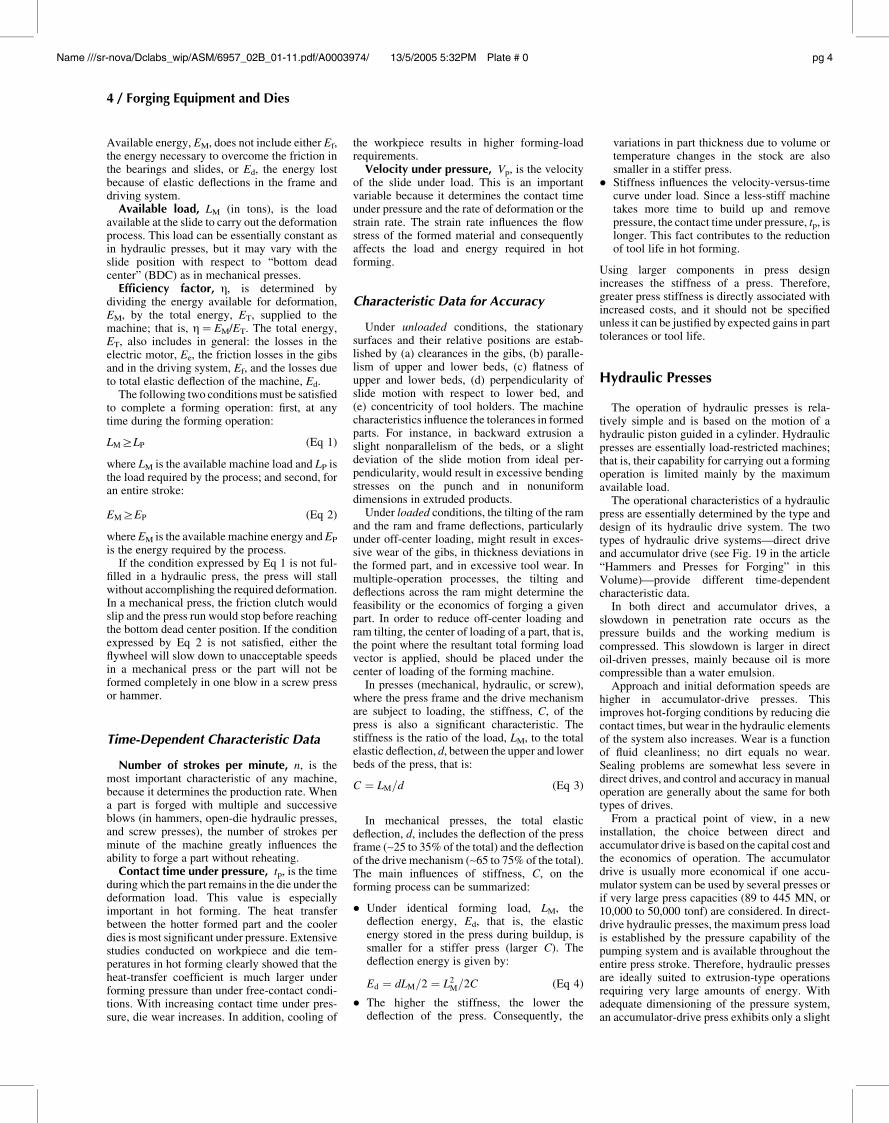
Hydraulic presses are essentially load-restricted machines; that is, their capability forcarrying out a forming operation is limitedmainly by the maximum load capacity.Mechanical (eccentric or crank) presses arestroke-restricted machines, since the length ofthe press stroke and the available load at variousstroke positions represent the capability of thesemachines. Hammers are energy-restrictedmachines, since the deformation results fromdissipating the kinetic energy of the hammerram. The hammer frame guides the ram, but isessentially not stressed during forging. Thescrew presses are also energy-restrictedmachines, but they are similar to the hydraulicand mechanical presses since their frames aresubject to loading during forging stroke. Thespeed range and the speed stroke behavior ofdifferent forging machines vary considerablyaccording to machine design, as illustrated inTable 1.
The significant characteristics of thesemachines comprise all machine design and per-formance data, which are pertinent to the eco-nomic use of the machine. These characteristicsinclude:
� Characteristics for load and energy� Time-related characteristics� Characteristics for accuracy
In addition to these characteristic parameters, thegeometric features of the machine such as thestroke in a press or hammer and the dimensionsand features of the tool-mounting space (shut
height) are also important. More information onthese machines is available in the article “Ham-mers and Presses for Forging” in this Volume.Other important values are the general machinedata, space requirements, weight, and the asso-ciated power requirements.
Horizontal forging machines or upsetters areessentially horizontal mechanical presses withdies that can be split in a direction perpendicularto the ram motion. More information on thesemachines is available in the article “Hot UpsetForging.”
Apart from the features mentioned previously,some of the basic requirements that are expectedof a good horizontal forging machine are:
� Tool pressure must be high, which requiresthe stock to be tightly gripped and upsettingforces completely absorbed.
� Tool length must be sufficient to permit rigidbar reception apart from filling up theimpression.
� The gripping tools must not open during theupsetting process.
� The device for moving the tools must besecured against overloading.
� The heading slide must be provided with longand accurate guides.
� The whole machine must be elasticallysecured against overloading.
� Crankshaft must be designed for specialrigidity.
� Gripping and heading tools must be readilyinterchangeable.
� The driving motor and the machine must beconnected through a security coupling.
� The machine must have central lubrication.
Characteristic Data for Loadand Energy
Available energy, EM (in ft . lbf or m . kg),is the energy supplied by the machine to carryout the deformation during an entire stroke.
0 5 10 15 20 250
27.5
55
82.5
U.S
. ton
s
For
ging
load
, met
ric to
ns
110
137.5
165
192.51.00.80.60.40.2
Displacement (ho − h), in.
Displacement (ho − h), mm
0175
150
125
100
75
50
25
0
1.18
1.58
Hydraulic press (Vpi = 0.33 ft/s) (0.1 m/s)
Screw press(Vpi = 0.96 ft/s) (0.29 m/s)
Dimensions arein inches
Drop hammer(Vpi = 21.1 ft/s) (6.4 m/s)
Fig. 3 Load-versus-displacement curves obtained in closed-die forging an axisymmetric steel part at 1100 �C(2012 �F) in three different machines with different initial velocities (Vpi)
Table 1 Speed-range and speed-stroke behavior of forging equipment
Forging machine
Speed range
Speed-stroke behaviorft/s m/s
Hydraulic press 0.2–1.0(a) 0.06–0.30(a)
Mechanical Press 0.2 � 5 0.06–1.5
Screw press 2–4 0.6–1.2
Spe
ed
Stroke
Gravity-drop hammer 12–16 3.6–4.8Power-drop hammer 10–30 3.0–9.0Counterblow hammer 15–30 4.5–9.0
Total speed 20–80 6.0–12.0HERF(b) Machines 8–20 2.4–6.0
(a) Lower speeds are valid for larger-capacity presses
(b) High energy rate forging. Source: Ref 3
Selection of Forging Equipment / 3
Name ///sr-nova/Dclabs_wip/ASM/6957_02B_01-11.pdf/A0003974/ 13/5/2005 5:32PM Plate # 0 pg 3
Available energy, EM, does not include either Ef,the energy necessary to overcome the friction inthe bearings and slides, or Ed, the energy lostbecause of elastic deflections in the frame anddriving system.
Available load, LM (in tons), is the loadavailable at the slide to carry out the deformationprocess. This load can be essentially constant asin hydraulic presses, but it may vary with theslide position with respect to “bottom deadcenter” (BDC) as in mechanical presses.
Efficiency factor, g, is determined bydividing the energy available for deformation,EM, by the total energy, ET, supplied to themachine; that is, g=EM/ET. The total energy,ET, also includes in general: the losses in theelectric motor, Ee, the friction losses in the gibsand in the driving system, Ef, and the losses dueto total elastic deflection of the machine, Ed.
The following two conditions must be satisfiedto complete a forming operation: first, at anytime during the forming operation:
LMiLP (Eq 1)
where LM is the available machine load and LP isthe load required by the process; and second, foran entire stroke:
EMiEP (Eq 2)
where EM is the available machine energy and EP
is the energy required by the process.If the condition expressed by Eq 1 is not ful-
filled in a hydraulic press, the press will stallwithout accomplishing the required deformation.In a mechanical press, the friction clutch wouldslip and the press run would stop before reachingthe bottom dead center position. If the conditionexpressed by Eq 2 is not satisfied, either theflywheel will slow down to unacceptable speedsin a mechanical press or the part will not beformed completely in one blow in a screw pressor hammer.
Time-Dependent Characteristic Data
Number of strokes per minute, n, is themost important characteristic of any machine,because it determines the production rate. Whena part is forged with multiple and successiveblows (in hammers, open-die hydraulic presses,and screw presses), the number of strokes perminute of the machine greatly influences theability to forge a part without reheating.
Contact time under pressure, tp, is the timeduring which the part remains in the die under thedeformation load. This value is especiallyimportant in hot forming. The heat transferbetween the hotter formed part and the coolerdies is most significant under pressure. Extensivestudies conducted on workpiece and die tem-peratures in hot forming clearly showed that theheat-transfer coefficient is much larger underforming pressure than under free-contact condi-tions. With increasing contact time under pres-sure, die wear increases. In addition, cooling of
the workpiece results in higher forming-loadrequirements.
Velocity under pressure, Vp, is the velocityof the slide under load. This is an importantvariable because it determines the contact timeunder pressure and the rate of deformation or thestrain rate. The strain rate influences the flowstress of the formed material and consequentlyaffects the load and energy required in hotforming.
Characteristic Data for Accuracy
Under unloaded conditions, the stationarysurfaces and their relative positions are estab-lished by (a) clearances in the gibs, (b) paralle-lism of upper and lower beds, (c) flatness ofupper and lower beds, (d) perpendicularity ofslide motion with respect to lower bed, and(e) concentricity of tool holders. The machinecharacteristics influence the tolerances in formedparts. For instance, in backward extrusion aslight nonparallelism of the beds, or a slightdeviation of the slide motion from ideal per-pendicularity, would result in excessive bendingstresses on the punch and in nonuniformdimensions in extruded products.
Under loaded conditions, the tilting of the ramand the ram and frame deflections, particularlyunder off-center loading, might result in exces-sive wear of the gibs, in thickness deviations inthe formed part, and in excessive tool wear. Inmultiple-operation processes, the tilting anddeflections across the ram might determine thefeasibility or the economics of forging a givenpart. In order to reduce off-center loading andram tilting, the center of loading of a part, that is,the point where the resultant total forming loadvector is applied, should be placed under thecenter of loading of the forming machine.
In presses (mechanical, hydraulic, or screw),where the press frame and the drive mechanismare subject to loading, the stiffness, C, of thepress is also a significant characteristic. Thestiffness is the ratio of the load, LM, to the totalelastic deflection, d, between the upper and lowerbeds of the press, that is:
C ¼ LM=d (Eq 3)
In mechanical presses, the total elasticdeflection, d, includes the deflection of the pressframe (~25 to 35% of the total) and the deflectionof the drive mechanism (~65 to 75% of the total).The main influences of stiffness, C, on theforming process can be summarized:
� Under identical forming load, LM, thedeflection energy, Ed, that is, the elasticenergy stored in the press during buildup, issmaller for a stiffer press (larger C). Thedeflection energy is given by:
Ed ¼ dLM=2 ¼ L2M=2C (Eq 4)
� The higher the stiffness, the lower thedeflection of the press. Consequently, the
variations in part thickness due to volume ortemperature changes in the stock are alsosmaller in a stiffer press.
� Stiffness influences the velocity-versus-timecurve under load. Since a less-stiff machinetakes more time to build up and removepressure, the contact time under pressure, tp, islonger. This fact contributes to the reductionof tool life in hot forming.
Using larger components in press designincreases the stiffness of a press. Therefore,greater press stiffness is directly associated withincreased costs, and it should not be specifiedunless it can be justified by expected gains in parttolerances or tool life.
Hydraulic Presses
The operation of hydraulic presses is rela-tively simple and is based on the motion of ahydraulic piston guided in a cylinder. Hydraulicpresses are essentially load-restricted machines;that is, their capability for carrying out a formingoperation is limited mainly by the maximumavailable load.
The operational characteristics of a hydraulicpress are essentially determined by the type anddesign of its hydraulic drive system. The twotypes of hydraulic drive systems—direct driveand accumulator drive (see Fig. 19 in the article“Hammers and Presses for Forging” in thisVolume)—provide different time-dependentcharacteristic data.
In both direct and accumulator drives, aslowdown in penetration rate occurs as thepressure builds and the working medium iscompressed. This slowdown is larger in directoil-driven presses, mainly because oil is morecompressible than a water emulsion.
Approach and initial deformation speeds arehigher in accumulator-drive presses. Thisimproves hot-forging conditions by reducing diecontact times, but wear in the hydraulic elementsof the system also increases. Wear is a functionof fluid cleanliness; no dirt equals no wear.Sealing problems are somewhat less severe indirect drives, and control and accuracy in manualoperation are generally about the same for bothtypes of drives.
From a practical point of view, in a newinstallation, the choice between direct andaccumulator drive is based on the capital cost andthe economics of operation. The accumulatordrive is usually more economical if one accu-mulator system can be used by several presses orif very large press capacities (89 to 445 MN, or10,000 to 50,000 tonf) are considered. In direct-drive hydraulic presses, the maximum press loadis established by the pressure capability of thepumping system and is available throughout theentire press stroke. Therefore, hydraulic pressesare ideally suited to extrusion-type operationsrequiring very large amounts of energy. Withadequate dimensioning of the pressure system,an accumulator-drive press exhibits only a slight
4 / Forging Equipment and Dies
Name ///sr-nova/Dclabs_wip/ASM/6957_02B_01-11.pdf/A0003974/ 13/5/2005 5:32PM Plate # 0 pg 4
reduction in available press load as the formingoperation proceeds.
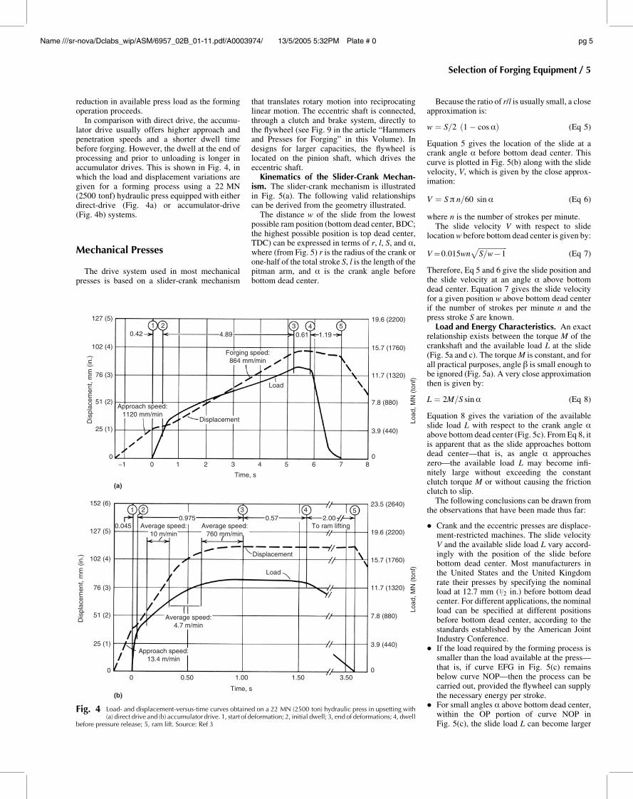
In comparison with direct drive, the accumu-lator drive usually offers higher approach andpenetration speeds and a shorter dwell timebefore forging. However, the dwell at the end ofprocessing and prior to unloading is longer inaccumulator drives. This is shown in Fig. 4, inwhich the load and displacement variations aregiven for a forming process using a 22 MN(2500 tonf) hydraulic press equipped with eitherdirect-drive (Fig. 4a) or accumulator-drive(Fig. 4b) systems.
Mechanical Presses
The drive system used in most mechanicalpresses is based on a slider-crank mechanism
that translates rotary motion into reciprocatinglinear motion. The eccentric shaft is connected,through a clutch and brake system, directly tothe flywheel (see Fig. 9 in the article “Hammersand Presses for Forging” in this Volume). Indesigns for larger capacities, the flywheel islocated on the pinion shaft, which drives theeccentric shaft.
Kinematics of the Slider-Crank Mechan-ism. The slider-crank mechanism is illustratedin Fig. 5(a). The following valid relationshipscan be derived from the geometry illustrated.
The distance w of the slide from the lowestpossible ram position (bottom dead center, BDC;the highest possible position is top dead center,TDC) can be expressed in terms of r, l, S, and a,where (from Fig. 5) r is the radius of the crank orone-half of the total stroke S, l is the length of thepitman arm, and a is the crank angle beforebottom dead center.
Because the ratio of r/l is usually small, a closeapproximation is:
w ¼ S=2 ð1 � cosaÞ (Eq 5)
Equation 5 gives the location of the slide at acrank angle a before bottom dead center. Thiscurve is plotted in Fig. 5(b) along with the slidevelocity, V, which is given by the close approx-imation:
V ¼ Sp n=60 sina (Eq 6)
where n is the number of strokes per minute.The slide velocity V with respect to slide
location w before bottom dead center is given by:
V=0:015wnffiffiffiffiffiffiffiffiffiffiffiffiffiffiffiffiS=w71
p(Eq 7)
Therefore, Eq 5 and 6 give the slide position andthe slide velocity at an angle a above bottomdead center. Equation 7 gives the slide velocityfor a given position w above bottom dead centerif the number of strokes per minute n and thepress stroke S are known.
Load and Energy Characteristics. An exactrelationship exists between the torque M of thecrankshaft and the available load L at the slide(Fig. 5a and c). The torque M is constant, and forall practical purposes, angle b is small enough tobe ignored (Fig. 5a). A very close approximationthen is given by:
L ¼ 2M=S sina (Eq 8)
Equation 8 gives the variation of the availableslide load L with respect to the crank angle aabove bottom dead center (Fig. 5c). From Eq 8, itis apparent that as the slide approaches bottomdead center—that is, as angle a approacheszero—the available load L may become infi-nitely large without exceeding the constantclutch torque M or without causing the frictionclutch to slip.
The following conclusions can be drawn fromthe observations that have been made thus far:
� Crank and the eccentric presses are displace-ment-restricted machines. The slide velocityV and the available slide load L vary accord-ingly with the position of the slide beforebottom dead center. Most manufacturers inthe United States and the United Kingdomrate their presses by specifying the nominalload at 12.7 mm (1/2 in.) before bottom deadcenter. For different applications, the nominalload can be specified at different positionsbefore bottom dead center, according to thestandards established by the American JointIndustry Conference.
� If the load required by the forming process issmaller than the load available at the press—that is, if curve EFG in Fig. 5(c) remainsbelow curve NOP—then the process can becarried out, provided the flywheel can supplythe necessary energy per stroke.
� For small angles a above bottom dead center,within the OP portion of curve NOP inFig. 5(c), the slide load L can become larger
127 (5)
102 (4)
76 (3)
Dis
plac
emen
t, m
m (
in.)
Load
, MN
(to
nf)
51 (2)Approach speed:
1120 mm/min
25 (1)
0
152 (6)
127 (5)
102 (4)
76 (3)
Dis
plac
emen
t, m
m (
in.)
51 (2)
25 (1)
00 0.50
Approach speed:13.4 m/min
Average speed:4.7 m/min
1.00
Time, s
1.50 3.50
3.9 (440)
0
7.8 (880)
11.7 (1320)
Load
, MN
(to
nf)
15.7 (1760)
19.6 (2200)
23.5 (2640)54321
0.045 Average speed:10 m/min
Average speed:760 mm/min
To ram lifting2.000.57
Displacement
Load
0.975
−1
(a)
(b)
0 1 2 3
Time, s
4 5 6 7 80
7.8 (880)
3.9 (440)
11.7 (1320)
15.7 (1760)
19.6 (2200)543
0.61 1.194.89
Forging speed:864 mm/min
Load
210.42
Displacement
Fig. 4 Load- and displacement-versus-time curves obtained on a 22 MN (2500 ton) hydraulic press in upsetting with(a) direct drive and (b) accumulator drive. 1, start of deformation; 2, initial dwell; 3, end of deformations; 4, dwell
before pressure release; 5, ram lift. Source: Ref 3
Selection of Forging Equipment / 5
Name ///sr-nova/Dclabs_wip/ASM/6957_02B_01-11.pdf/A0003974/ 13/5/2005 5:32PM Plate # 0 pg 5
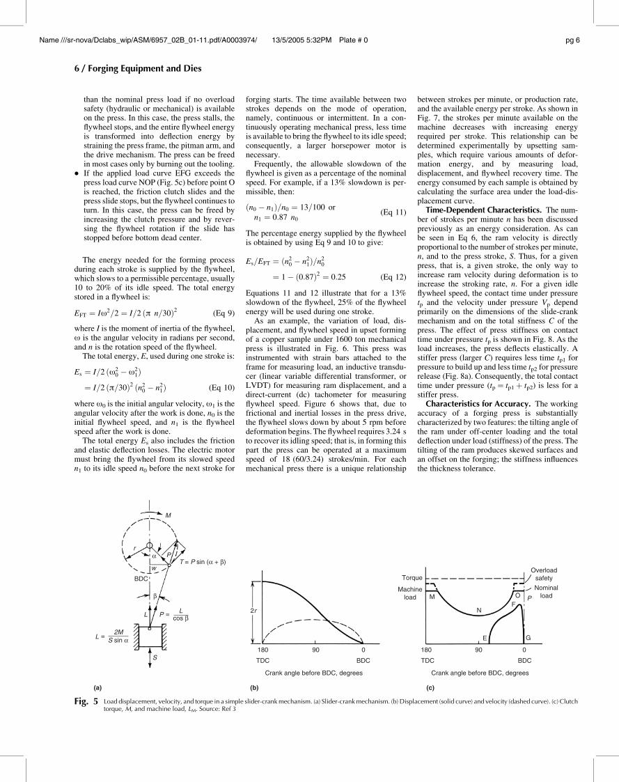
than the nominal press load if no overloadsafety (hydraulic or mechanical) is availableon the press. In this case, the press stalls, theflywheel stops, and the entire flywheel energyis transformed into deflection energy bystraining the press frame, the pitman arm, andthe drive mechanism. The press can be freedin most cases only by burning out the tooling.
� If the applied load curve EFG exceeds thepress load curve NOP (Fig. 5c) before point Ois reached, the friction clutch slides and thepress slide stops, but the flywheel continues toturn. In this case, the press can be freed byincreasing the clutch pressure and by rever-sing the flywheel rotation if the slide hasstopped before bottom dead center.
The energy needed for the forming processduring each stroke is supplied by the flywheel,which slows to a permissible percentage, usually10 to 20% of its idle speed. The total energystored in a flywheel is:
EFT ¼ Iv2=2 ¼ I=2 ðp n=30Þ2(Eq 9)
where I is the moment of inertia of the flywheel,v is the angular velocity in radians per second,and n is the rotation speed of the flywheel.
The total energy, E, used during one stroke is:
Es ¼ I=2 ðv20 � v2
1Þ
¼ I=2 ðp=30Þ2 ðn20 � n2
1Þ (Eq 10)
where v0 is the initial angular velocity, v1 is theangular velocity after the work is done, n0 is theinitial flywheel speed, and n1 is the flywheelspeed after the work is done.
The total energy Es also includes the frictionand elastic deflection losses. The electric motormust bring the flywheel from its slowed speedn1 to its idle speed n0 before the next stroke for
forging starts. The time available between twostrokes depends on the mode of operation,namely, continuous or intermittent. In a con-tinuously operating mechanical press, less timeis available to bring the flywheel to its idle speed;consequently, a larger horsepower motor isnecessary.
Frequently, the allowable slowdown of theflywheel is given as a percentage of the nominalspeed. For example, if a 13% slowdown is per-missible, then:
ðn0 � n1Þ=n0 ¼ 13=100 or
n1 ¼ 0:87 n0(Eq 11)
The percentage energy supplied by the flywheelis obtained by using Eq 9 and 10 to give:
Es=EFT ¼ ðn20 � n2
1Þ=n20
¼ 1 � ð0:87Þ2 ¼ 0:25 (Eq 12)
Equations 11 and 12 illustrate that for a 13%slowdown of the flywheel, 25% of the flywheelenergy will be used during one stroke.
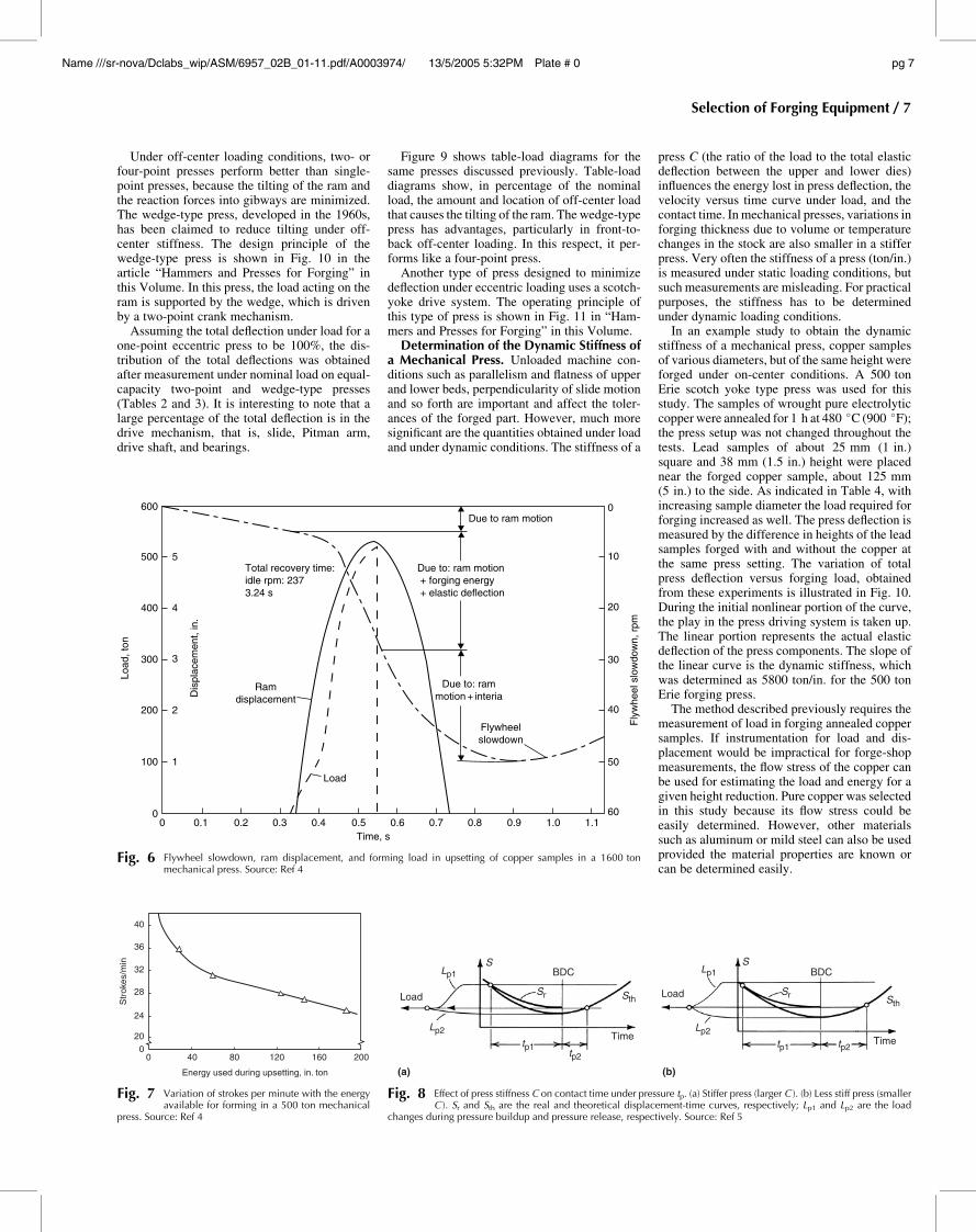
As an example, the variation of load, dis-placement, and flywheel speed in upset formingof a copper sample under 1600 ton mechanicalpress is illustrated in Fig. 6. This press wasinstrumented with strain bars attached to theframe for measuring load, an inductive transdu-cer (linear variable differential transformer, orLVDT) for measuring ram displacement, and adirect-current (dc) tachometer for measuringflywheel speed. Figure 6 shows that, due tofrictional and inertial losses in the press drive,the flywheel slows down by about 5 rpm beforedeformation begins. The flywheel requires 3.24 sto recover its idling speed; that is, in forming thispart the press can be operated at a maximumspeed of 18 (60/3.24) strokes/min. For eachmechanical press there is a unique relationship
between strokes per minute, or production rate,and the available energy per stroke. As shown inFig. 7, the strokes per minute available on themachine decreases with increasing energyrequired per stroke. This relationship can bedetermined experimentally by upsetting sam-ples, which require various amounts of defor-mation energy, and by measuring load,displacement, and flywheel recovery time. Theenergy consumed by each sample is obtained bycalculating the surface area under the load-dis-placement curve.
Time-Dependent Characteristics. The num-ber of strokes per minute n has been discussedpreviously as an energy consideration. As canbe seen in Eq 6, the ram velocity is directlyproportional to the number of strokes per minute,n, and to the press stroke, S. Thus, for a givenpress, that is, a given stroke, the only way toincrease ram velocity during deformation is toincrease the stroking rate, n. For a given idleflywheel speed, the contact time under pressuretp and the velocity under pressure Vp dependprimarily on the dimensions of the slide-crankmechanism and on the total stiffness C of thepress. The effect of press stiffness on contacttime under pressure tp is shown in Fig. 8. As theload increases, the press deflects elastically. Astiffer press (larger C) requires less time tp1 forpressure to build up and less time tp2 for pressurerelease (Fig. 8a). Consequently, the total contacttime under pressure (tp= tp1 þ tp2) is less for astiffer press.
Characteristics for Accuracy. The workingaccuracy of a forging press is substantiallycharacterized by two features: the tilting angle ofthe ram under off-center loading and the totaldeflection under load (stiffness) of the press. Thetilting of the ram produces skewed surfaces andan offset on the forging; the stiffness influencesthe thickness tolerance.
M
r
w
BDC
L
S
(a) (b) (c)
P
L2M
=
= L 2r
180
TDC
Crank angle before BDC, degrees Crank angle before BDC, degrees
BDC TDC BDC
90 0
Torque
Machineload
NominalloadM
N
E
FO
Overloadsafety
G
P
180 90 0
cos β
S sin α
β
PT = P sin (α + β)
α
Fig. 5 Load displacement, velocity, and torque in a simple slider-crankmechanism. (a) Slider-crankmechanism. (b) Displacement (solid curve) and velocity (dashed curve). (c) Clutchtorque, M, and machine load, LM. Source: Ref 3
6 / Forging Equipment and Dies
Name ///sr-nova/Dclabs_wip/ASM/6957_02B_01-11.pdf/A0003974/ 13/5/2005 5:32PM Plate # 0 pg 6
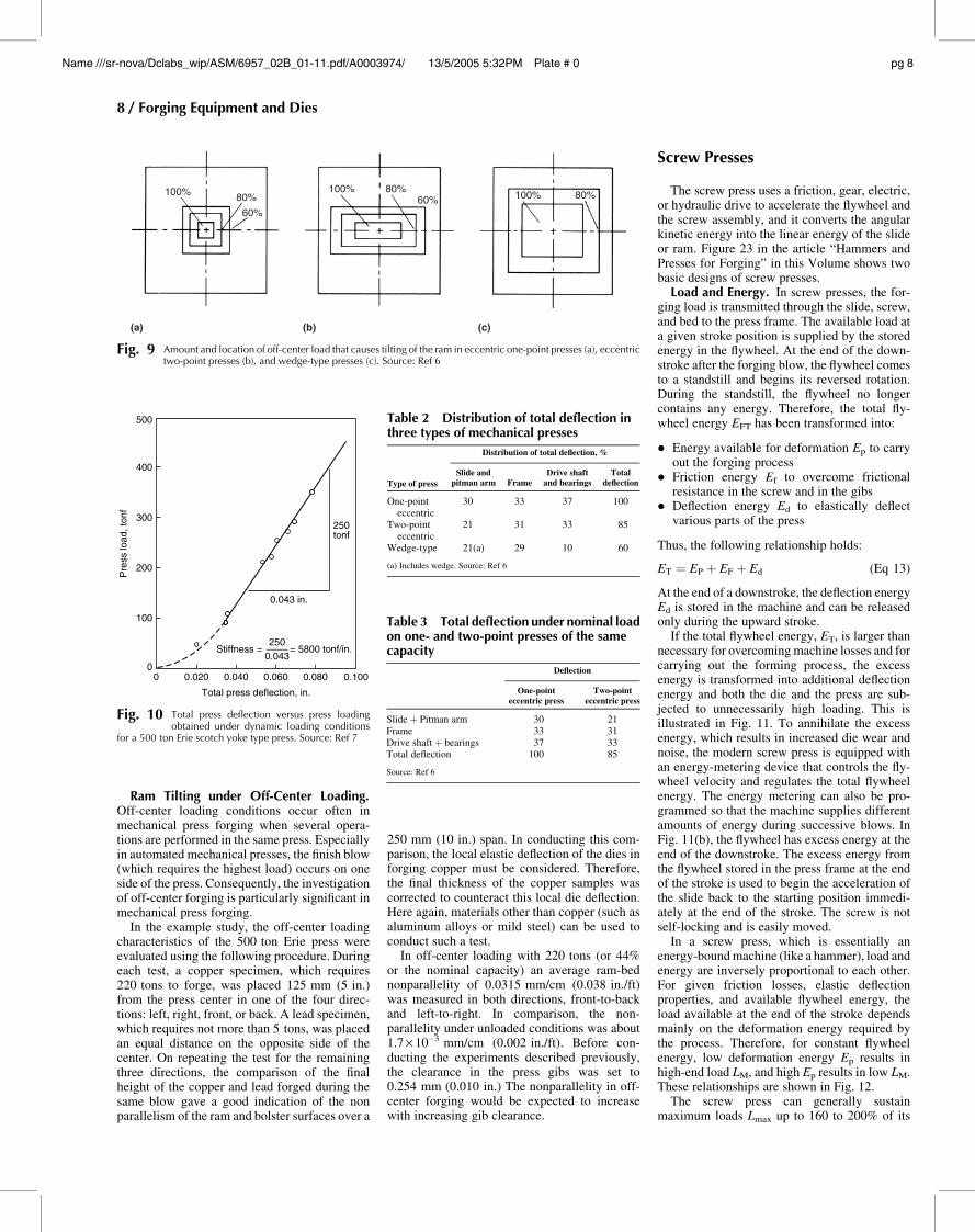
Under off-center loading conditions, two- orfour-point presses perform better than single-point presses, because the tilting of the ram andthe reaction forces into gibways are minimized.The wedge-type press, developed in the 1960s,has been claimed to reduce tilting under off-center stiffness. The design principle of thewedge-type press is shown in Fig. 10 in thearticle “Hammers and Presses for Forging” inthis Volume. In this press, the load acting on theram is supported by the wedge, which is drivenby a two-point crank mechanism.
Assuming the total deflection under load for aone-point eccentric press to be 100%, the dis-tribution of the total deflections was obtainedafter measurement under nominal load on equal-capacity two-point and wedge-type presses(Tables 2 and 3). It is interesting to note that alarge percentage of the total deflection is in thedrive mechanism, that is, slide, Pitman arm,drive shaft, and bearings.
Figure 9 shows table-load diagrams for thesame presses discussed previously. Table-loaddiagrams show, in percentage of the nominalload, the amount and location of off-center loadthat causes the tilting of the ram. The wedge-typepress has advantages, particularly in front-to-back off-center loading. In this respect, it per-forms like a four-point press.
Another type of press designed to minimizedeflection under eccentric loading uses a scotch-yoke drive system. The operating principle ofthis type of press is shown in Fig. 11 in “Ham-mers and Presses for Forging” in this Volume.
Determination of the Dynamic Stiffness ofa Mechanical Press. Unloaded machine con-ditions such as parallelism and flatness of upperand lower beds, perpendicularity of slide motionand so forth are important and affect the toler-ances of the forged part. However, much moresignificant are the quantities obtained under loadand under dynamic conditions. The stiffness of a
press C (the ratio of the load to the total elasticdeflection between the upper and lower dies)influences the energy lost in press deflection, thevelocity versus time curve under load, and thecontact time. In mechanical presses, variations inforging thickness due to volume or temperaturechanges in the stock are also smaller in a stifferpress. Very often the stiffness of a press (ton/in.)is measured under static loading conditions, butsuch measurements are misleading. For practicalpurposes, the stiffness has to be determinedunder dynamic loading conditions.
In an example study to obtain the dynamicstiffness of a mechanical press, copper samplesof various diameters, but of the same height wereforged under on-center conditions. A 500 tonErie scotch yoke type press was used for thisstudy. The samples of wrought pure electrolyticcopper were annealed for 1 h at 480 �C (900 �F);the press setup was not changed throughout thetests. Lead samples of about 25 mm (1 in.)square and 38 mm (1.5 in.) height were placednear the forged copper sample, about 125 mm(5 in.) to the side. As indicated in Table 4, withincreasing sample diameter the load required forforging increased as well. The press deflection ismeasured by the difference in heights of the leadsamples forged with and without the copper atthe same press setting. The variation of totalpress deflection versus forging load, obtainedfrom these experiments is illustrated in Fig. 10.During the initial nonlinear portion of the curve,the play in the press driving system is taken up.The linear portion represents the actual elasticdeflection of the press components. The slope ofthe linear curve is the dynamic stiffness, whichwas determined as 5800 ton/in. for the 500 tonErie forging press.
The method described previously requires themeasurement of load in forging annealed coppersamples. If instrumentation for load and dis-placement would be impractical for forge-shopmeasurements, the flow stress of the copper canbe used for estimating the load and energy for agiven height reduction. Pure copper was selectedin this study because its flow stress could beeasily determined. However, other materialssuch as aluminum or mild steel can also be usedprovided the material properties are known orcan be determined easily.
40
36
32
28
24
Str
okes
/min
200
0 40
Energy used during upsetting, in. ton
80 120 160 200
Fig. 7 Variation of strokes per minute with the energyavailable for forming in a 500 ton mechanical
press. Source: Ref 4
Load
Lp2
Lp1
Sr
BDC BDC
Time
(a) (b)
Time
LoadSth
S
Sr Sth
tp1tp2
tp2tp1
Lp1
Lp2
S
Fig. 8 Effect of press stiffness C on contact time under pressure tp. (a) Stiffer press (larger C ). (b) Less stiff press (smallerC ). Sr and Sth are the real and theoretical displacement-time curves, respectively; Lp1 and Lp2 are the load
changes during pressure buildup and pressure release, respectively. Source: Ref 5
00
100
200 2
Load
, ton
Dis
plac
emen
t, in
.
3
400
300
4
500
600
5Total recovery time:idle rpm: 2373.24 s
Due to ram motion
Flywheelslowdown
1
0.1 0.2 0.3 0.4
Load
0.5Time, s
0.6 0.7 0.8 0.9 1.0 1.160
50
40
30
Fly
whe
el s
low
dow
n, r
pm
20
10
0
Ramdisplacement
Due to: ram motion + forging energy + elastic deflection
Due to: rammotion + interia
Fig. 6 Flywheel slowdown, ram displacement, and forming load in upsetting of copper samples in a 1600 tonmechanical press. Source: Ref 4
Selection of Forging Equipment / 7
Name ///sr-nova/Dclabs_wip/ASM/6957_02B_01-11.pdf/A0003974/ 13/5/2005 5:32PM Plate # 0 pg 7
Ram Tilting under Off-Center Loading.Off-center loading conditions occur often inmechanical press forging when several opera-tions are performed in the same press. Especiallyin automated mechanical presses, the finish blow(which requires the highest load) occurs on oneside of the press. Consequently, the investigationof off-center forging is particularly significant inmechanical press forging.
In the example study, the off-center loadingcharacteristics of the 500 ton Erie press wereevaluated using the following procedure. Duringeach test, a copper specimen, which requires220 tons to forge, was placed 125 mm (5 in.)from the press center in one of the four direc-tions: left, right, front, or back. A lead specimen,which requires not more than 5 tons, was placedan equal distance on the opposite side of thecenter. On repeating the test for the remainingthree directions, the comparison of the finalheight of the copper and lead forged during thesame blow gave a good indication of the nonparallelism of the ram and bolster surfaces over a
250 mm (10 in.) span. In conducting this com-parison, the local elastic deflection of the dies inforging copper must be considered. Therefore,the final thickness of the copper samples wascorrected to counteract this local die deflection.Here again, materials other than copper (such asaluminum alloys or mild steel) can be used toconduct such a test.
In off-center loading with 220 tons (or 44%or the nominal capacity) an average ram-bednonparallelity of 0.0315 mm/cm (0.038 in./ft)was measured in both directions, front-to-backand left-to-right. In comparison, the non-parallelity under unloaded conditions was about1.7 · 10�3 mm/cm (0.002 in./ft). Before con-ducting the experiments described previously,the clearance in the press gibs was set to0.254 mm (0.010 in.) The nonparallelity in off-center forging would be expected to increasewith increasing gib clearance.
Screw Presses
The screw press uses a friction, gear, electric,or hydraulic drive to accelerate the flywheel andthe screw assembly, and it converts the angularkinetic energy into the linear energy of the slideor ram. Figure 23 in the article “Hammers andPresses for Forging” in this Volume shows twobasic designs of screw presses.
Load and Energy. In screw presses, the for-ging load is transmitted through the slide, screw,and bed to the press frame. The available load ata given stroke position is supplied by the storedenergy in the flywheel. At the end of the down-stroke after the forging blow, the flywheel comesto a standstill and begins its reversed rotation.During the standstill, the flywheel no longercontains any energy. Therefore, the total fly-wheel energy EFT has been transformed into:
� Energy available for deformation Ep to carryout the forging process
� Friction energy Ef to overcome frictionalresistance in the screw and in the gibs
� Deflection energy Ed to elastically deflectvarious parts of the press
Thus, the following relationship holds:
ET ¼ EP þ EF þ Ed (Eq 13)
At the end of a downstroke, the deflection energyEd is stored in the machine and can be releasedonly during the upward stroke.
If the total flywheel energy, ET, is larger thannecessary for overcoming machine losses and forcarrying out the forming process, the excessenergy is transformed into additional deflectionenergy and both the die and the press are sub-jected to unnecessarily high loading. This isillustrated in Fig. 11. To annihilate the excessenergy, which results in increased die wear andnoise, the modern screw press is equipped withan energy-metering device that controls the fly-wheel velocity and regulates the total flywheelenergy. The energy metering can also be pro-grammed so that the machine supplies differentamounts of energy during successive blows. InFig. 11(b), the flywheel has excess energy at theend of the downstroke. The excess energy fromthe flywheel stored in the press frame at the endof the stroke is used to begin the acceleration ofthe slide back to the starting position immedi-ately at the end of the stroke. The screw is notself-locking and is easily moved.
In a screw press, which is essentially anenergy-bound machine (like a hammer), load andenergy are inversely proportional to each other.For given friction losses, elastic deflectionproperties, and available flywheel energy, theload available at the end of the stroke dependsmainly on the deformation energy required bythe process. Therefore, for constant flywheelenergy, low deformation energy Ep results inhigh-end load LM, and high Ep results in low LM.These relationships are shown in Fig. 12.
The screw press can generally sustainmaximum loads Lmax up to 160 to 200% of its
100% 80%
60%
100% 80%60% 100% 80%
(c)(b)(a)
Fig. 9 Amount and location of off-center load that causes tilting of the ram in eccentric one-point presses (a), eccentrictwo-point presses (b), and wedge-type presses (c). Source: Ref 6
00
100
Pre
ss lo
ad, t
onf
200
400
300
500
0.020 0.040
Total press deflection, in.
Stiffness = = 5800 tonf/in.
0.060 0.080 0.100
250––––0.043
0.043 in.
250tonf
Fig. 10 Total press deflection versus press loadingobtained under dynamic loading conditions
for a 500 ton Erie scotch yoke type press. Source: Ref 7
Table 2 Distribution of total deflection inthree types of mechanical presses
Type of press
Distribution of total deflection, %
Slide andpitman arm Frame
Drive shaftand bearings
Totaldeflection
One-pointeccentric
30 33 37 100
Two-pointeccentric
21 31 33 85
Wedge-type 21(a) 29 10 60
(a) Includes wedge. Source: Ref 6
Table 3 Total deflection under nominal loadon one- and two-point presses of the samecapacity
Deflection
One-pointeccentric press
Two-pointeccentric press
Slide þ Pitman arm 30 21Frame 33 31Drive shaft þ bearings 37 33Total deflection 100 85
Source: Ref 6
8 / Forging Equipment and Dies
Name ///sr-nova/Dclabs_wip/ASM/6957_02B_01-11.pdf/A0003974/ 13/5/2005 5:32PM Plate # 0 pg 8
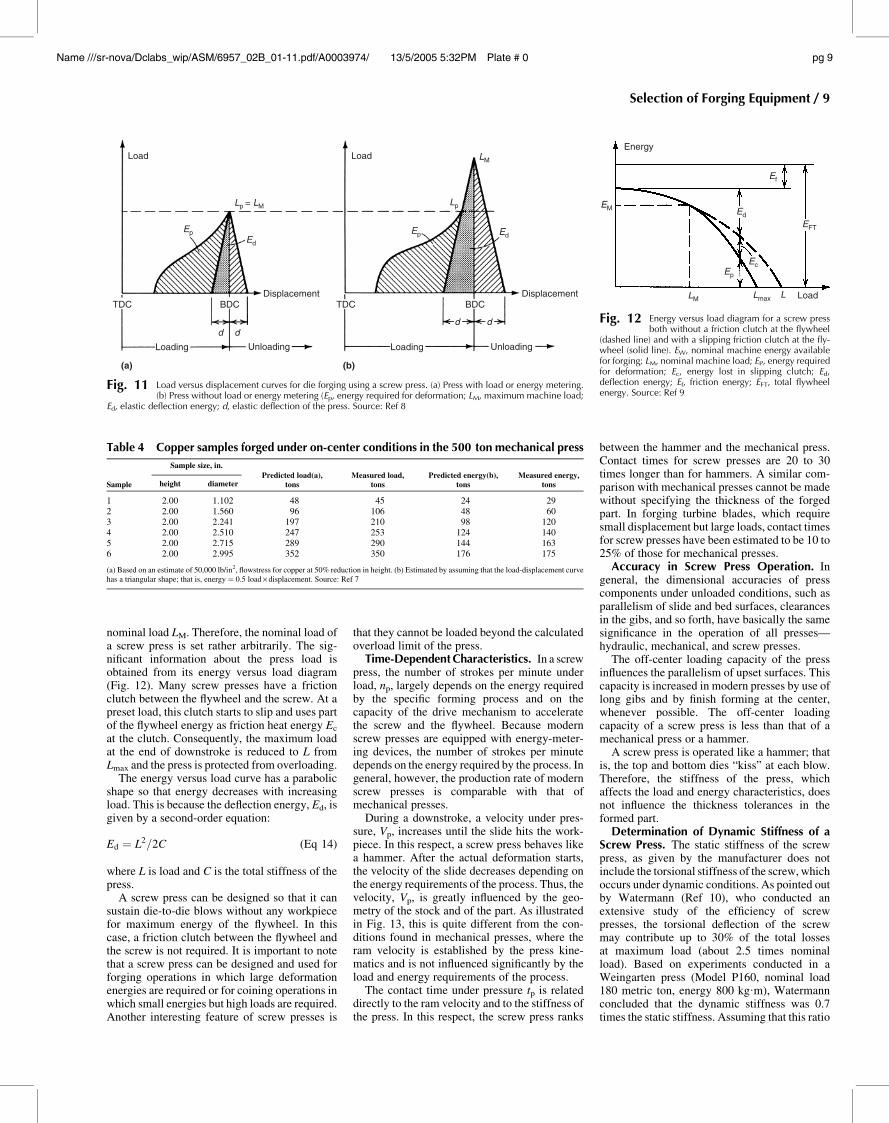
nominal load LM. Therefore, the nominal load ofa screw press is set rather arbitrarily. The sig-nificant information about the press load isobtained from its energy versus load diagram(Fig. 12). Many screw presses have a frictionclutch between the flywheel and the screw. At apreset load, this clutch starts to slip and uses partof the flywheel energy as friction heat energy Ec
at the clutch. Consequently, the maximum loadat the end of downstroke is reduced to L fromLmax and the press is protected from overloading.
The energy versus load curve has a parabolicshape so that energy decreases with increasingload. This is because the deflection energy, Ed, isgiven by a second-order equation:
Ed ¼ L2=2C (Eq 14)
where L is load and C is the total stiffness of thepress.
A screw press can be designed so that it cansustain die-to-die blows without any workpiecefor maximum energy of the flywheel. In thiscase, a friction clutch between the flywheel andthe screw is not required. It is important to notethat a screw press can be designed and used forforging operations in which large deformationenergies are required or for coining operations inwhich small energies but high loads are required.Another interesting feature of screw presses is
that they cannot be loaded beyond the calculatedoverload limit of the press.
Time-Dependent Characteristics. In a screwpress, the number of strokes per minute underload, np, largely depends on the energy requiredby the specific forming process and on thecapacity of the drive mechanism to acceleratethe screw and the flywheel. Because modernscrew presses are equipped with energy-meter-ing devices, the number of strokes per minutedepends on the energy required by the process. Ingeneral, however, the production rate of modernscrew presses is comparable with that ofmechanical presses.
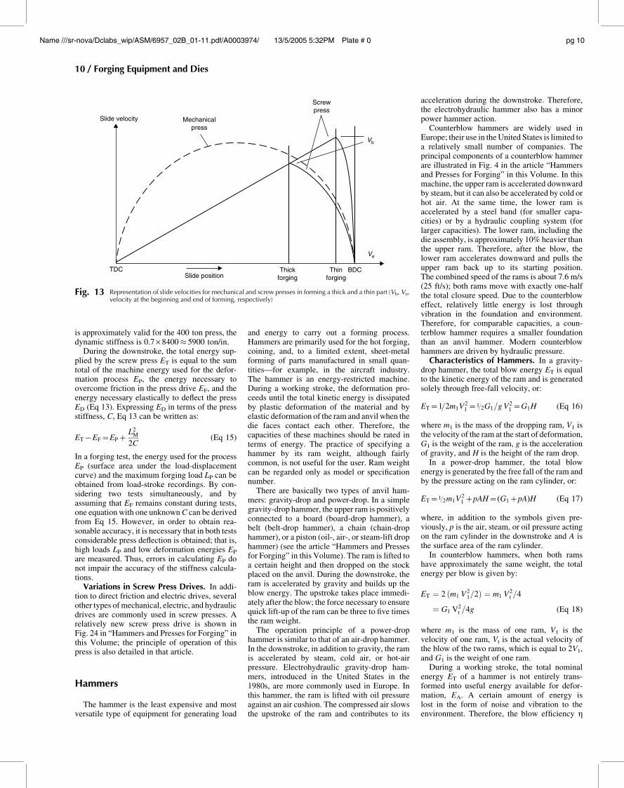
During a downstroke, a velocity under pres-sure, Vp, increases until the slide hits the work-piece. In this respect, a screw press behaves likea hammer. After the actual deformation starts,the velocity of the slide decreases depending onthe energy requirements of the process. Thus, thevelocity, Vp, is greatly influenced by the geo-metry of the stock and of the part. As illustratedin Fig. 13, this is quite different from the con-ditions found in mechanical presses, where theram velocity is established by the press kine-matics and is not influenced significantly by theload and energy requirements of the process.
The contact time under pressure tp is relateddirectly to the ram velocity and to the stiffness ofthe press. In this respect, the screw press ranks
between the hammer and the mechanical press.Contact times for screw presses are 20 to 30times longer than for hammers. A similar com-parison with mechanical presses cannot be madewithout specifying the thickness of the forgedpart. In forging turbine blades, which requiresmall displacement but large loads, contact timesfor screw presses have been estimated to be 10 to25% of those for mechanical presses.
Accuracy in Screw Press Operation. Ingeneral, the dimensional accuracies of presscomponents under unloaded conditions, such asparallelism of slide and bed surfaces, clearancesin the gibs, and so forth, have basically the samesignificance in the operation of all presses—hydraulic, mechanical, and screw presses.
The off-center loading capacity of the pressinfluences the parallelism of upset surfaces. Thiscapacity is increased in modern presses by use oflong gibs and by finish forming at the center,whenever possible. The off-center loadingcapacity of a screw press is less than that of amechanical press or a hammer.
A screw press is operated like a hammer; thatis, the top and bottom dies “kiss” at each blow.Therefore, the stiffness of the press, whichaffects the load and energy characteristics, doesnot influence the thickness tolerances in theformed part.
Determination of Dynamic Stiffness of aScrew Press. The static stiffness of the screwpress, as given by the manufacturer does notinclude the torsional stiffness of the screw, whichoccurs under dynamic conditions. As pointed outby Watermann (Ref 10), who conducted anextensive study of the efficiency of screwpresses, the torsional deflection of the screwmay contribute up to 30% of the total lossesat maximum load (about 2.5 times nominalload). Based on experiments conducted in aWeingarten press (Model P160, nominal load180 metric ton, energy 800 kg.m), Watermannconcluded that the dynamic stiffness was 0.7times the static stiffness. Assuming that this ratio
Loading
(a) (b)
Loading
d d
Unloading Unloading
Displacement DisplacementTDCTDC
Load Load
BDC BDC
d d
Ed
Ep
Lp
LM
EdEp
Lp = LM
Fig. 11 Load versus displacement curves for die forging using a screw press. (a) Press with load or energy metering.(b) Press without load or energy metering (Ep, energy required for deformation; LM, maximum machine load;
Ed, elastic deflection energy; d, elastic deflection of the press. Source: Ref 8
Table 4 Copper samples forged under on-center conditions in the 500 ton mechanical press
Sample
Sample size, in.
Predicted load(a),tons
Measured load,tons
Predicted energy(b),tons
Measured energy,tonsheight diameter
1 2.00 1.102 48 45 24 292 2.00 1.560 96 106 48 603 2.00 2.241 197 210 98 1204 2.00 2.510 247 253 124 1405 2.00 2.715 289 290 144 1636 2.00 2.995 352 350 176 175
(a) Based on an estimate of 50,000 lb/in2, flowstress for copper at 50% reduction in height. (b) Estimated by assuming that the load-displacement curvehas a triangular shape; that is, energy=0.5 load · displacement. Source: Ref 7
Energy
Lmax
Ed
Ec
EM
Ep
Ef
EFT
LM L Load
Fig. 12 Energy versus load diagram for a screw pressboth without a friction clutch at the flywheel
(dashed line) and with a slipping friction clutch at the fly-wheel (solid line). EW, nominal machine energy availablefor forging; LM, nominal machine load; EP, energy requiredfor deformation; Ec, energy lost in slipping clutch; Ed,deflection energy; Ef, friction energy; EFT, total flywheelenergy. Source: Ref 9
Selection of Forging Equipment / 9
Name ///sr-nova/Dclabs_wip/ASM/6957_02B_01-11.pdf/A0003974/ 13/5/2005 5:32PM Plate # 0 pg 9
is approximately valid for the 400 ton press, thedynamic stiffness is 0.7 · 8400� 5900 ton/in.
During the downstroke, the total energy sup-plied by the screw press ET is equal to the sumtotal of the machine energy used for the defor-mation process EP, the energy necessary toovercome friction in the press drive EF, and theenergy necessary elastically to deflect the pressED (Eq 13). Expressing ED in terms of the pressstiffness, C, Eq 13 can be written as:
ET7EF=EP+L2
M
2C(Eq 15)
In a forging test, the energy used for the processEP (surface area under the load-displacementcurve) and the maximum forging load LP can beobtained from load-stroke recordings. By con-sidering two tests simultaneously, and byassuming that EF remains constant during tests,one equation with one unknownC can be derivedfrom Eq 15. However, in order to obtain rea-sonable accuracy, it is necessary that in both testsconsiderable press deflection is obtained; that is,high loads LP and low deformation energies EP
are measured. Thus, errors in calculating EP donot impair the accuracy of the stiffness calcula-tions.
Variations in Screw Press Drives. In addi-tion to direct friction and electric drives, severalother types of mechanical, electric, and hydraulicdrives are commonly used in screw presses. Arelatively new screw press drive is shown inFig. 24 in “Hammers and Presses for Forging” inthis Volume; the principle of operation of thispress is also detailed in that article.
Hammers
The hammer is the least expensive and mostversatile type of equipment for generating load
and energy to carry out a forming process.Hammers are primarily used for the hot forging,coining, and, to a limited extent, sheet-metalforming of parts manufactured in small quan-tities—for example, in the aircraft industry.The hammer is an energy-restricted machine.During a working stroke, the deformation pro-ceeds until the total kinetic energy is dissipatedby plastic deformation of the material and byelastic deformation of the ram and anvil when thedie faces contact each other. Therefore, thecapacities of these machines should be rated interms of energy. The practice of specifying ahammer by its ram weight, although fairlycommon, is not useful for the user. Ram weightcan be regarded only as model or specificationnumber.
There are basically two types of anvil ham-mers: gravity-drop and power-drop. In a simplegravity-drop hammer, the upper ram is positivelyconnected to a board (board-drop hammer), abelt (belt-drop hammer), a chain (chain-drophammer), or a piston (oil-, air-, or steam-lift drophammer) (see the article “Hammers and Pressesfor Forging” in this Volume). The ram is lifted toa certain height and then dropped on the stockplaced on the anvil. During the downstroke, theram is accelerated by gravity and builds up theblow energy. The upstroke takes place immedi-ately after the blow; the force necessary to ensurequick lift-up of the ram can be three to five timesthe ram weight.
The operation principle of a power-drophammer is similar to that of an air-drop hammer.In the downstroke, in addition to gravity, the ramis accelerated by steam, cold air, or hot-airpressure. Electrohydraulic gravity-drop ham-mers, introduced in the United States in the1980s, are more commonly used in Europe. Inthis hammer, the ram is lifted with oil pressureagainst an air cushion. The compressed air slowsthe upstroke of the ram and contributes to its
acceleration during the downstroke. Therefore,the electrohydraulic hammer also has a minorpower hammer action.
Counterblow hammers are widely used inEurope; their use in the United States is limited toa relatively small number of companies. Theprincipal components of a counterblow hammerare illustrated in Fig. 4 in the article “Hammersand Presses for Forging” in this Volume. In thismachine, the upper ram is accelerated downwardby steam, but it can also be accelerated by cold orhot air. At the same time, the lower ram isaccelerated by a steel band (for smaller capa-cities) or by a hydraulic coupling system (forlarger capacities). The lower ram, including thedie assembly, is approximately 10% heavier thanthe upper ram. Therefore, after the blow, thelower ram accelerates downward and pulls theupper ram back up to its starting position.The combined speed of the rams is about 7.6 m/s(25 ft/s); both rams move with exactly one-halfthe total closure speed. Due to the counterbloweffect, relatively little energy is lost throughvibration in the foundation and environment.Therefore, for comparable capacities, a coun-terblow hammer requires a smaller foundationthan an anvil hammer. Modern counterblowhammers are driven by hydraulic pressure.
Characteristics of Hammers. In a gravity-drop hammer, the total blow energy ET is equalto the kinetic energy of the ram and is generatedsolely through free-fall velocity, or:
ET=1=2m1V21=1/2G1=gV
21=G1H (Eq 16)
where m1 is the mass of the dropping ram, V1 isthe velocity of the ram at the start of deformation,G1 is the weight of the ram, g is the accelerationof gravity, and H is the height of the ram drop.
In a power-drop hammer, the total blowenergy is generated by the free fall of the ram andby the pressure acting on the ram cylinder, or:
ET=1/2m1V21+pAH=(G1+pA)H (Eq 17)
where, in addition to the symbols given pre-viously, p is the air, steam, or oil pressure actingon the ram cylinder in the downstroke and A isthe surface area of the ram cylinder.
In counterblow hammers, when both ramshave approximately the same weight, the totalenergy per blow is given by:
ET ¼ 2 ðm1 V21=2Þ ¼ m1 V
2t =4
¼ G1 V2t =4g (Eq 18)
where m1 is the mass of one ram, V1 is thevelocity of one ram, Vt is the actual velocity ofthe blow of the two rams, which is equal to 2V1,and G1 is the weight of one ram.
During a working stroke, the total nominalenergy ET of a hammer is not entirely trans-formed into useful energy available for defor-mation, EA. A certain amount of energy islost in the form of noise and vibration to theenvironment. Therefore, the blow efficiency g
Slide velocity Mechanicalpress
Screwpress
Thinforging
Ve
Vb
Thickforging
BDCTDCSlide position
Fig. 13 Representation of slide velocities for mechanical and screw presses in forming a thick and a thin part (Vb, Ve,velocity at the beginning and end of forming, respectively)
10 / Forging Equipment and Dies
Name ///sr-nova/Dclabs_wip/ASM/6957_02B_01-11.pdf/A0003974/ 13/5/2005 5:32PM Plate # 0 pg 10
(g=EA/ET) of hammers varies from 0.8 to 0.9for soft blows (small load and large displace-ment) and from 0.2 to 0.5 for hard blows (highload and small displacement).
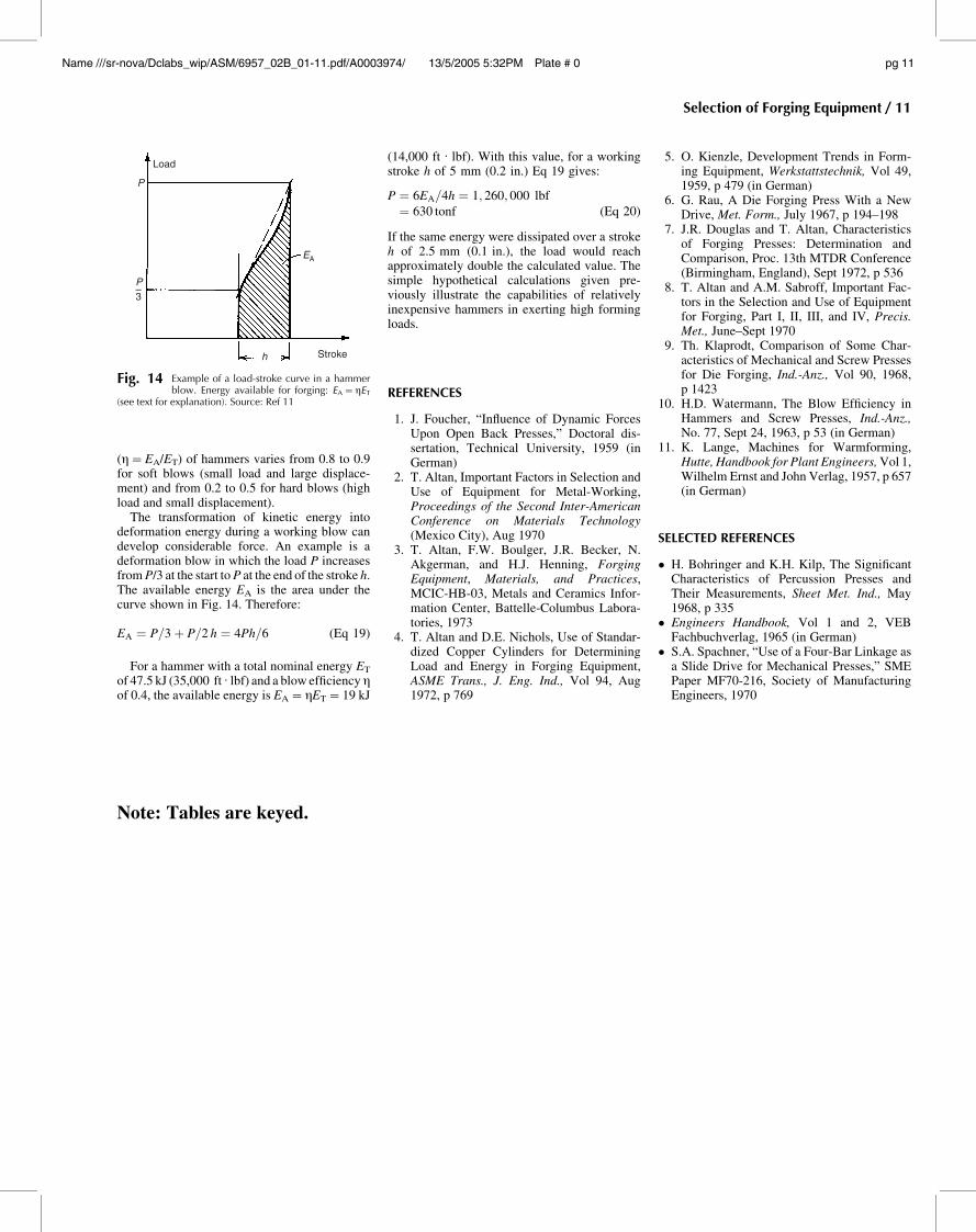
The transformation of kinetic energy intodeformation energy during a working blow candevelop considerable force. An example is adeformation blow in which the load P increasesfromP/3 at the start toP at the end of the stroke h.The available energy EA is the area under thecurve shown in Fig. 14. Therefore:
EA ¼ P=3 þ P=2 h ¼ 4Ph=6 (Eq 19)
For a hammer with a total nominal energy ET
of 47.5 kJ (35,000 ft . lbf) and a blow efficiency gof 0.4, the available energy is EA=gET=19 kJ
(14,000 ft . lbf). With this value, for a workingstroke h of 5 mm (0.2 in.) Eq 19 gives:
P ¼ 6EA=4h ¼ 1; 260; 000 lbf
¼ 630 tonf (Eq 20)
If the same energy were dissipated over a strokeh of 2.5 mm (0.1 in.), the load would reachapproximately double the calculated value. Thesimple hypothetical calculations given pre-viously illustrate the capabilities of relativelyinexpensive hammers in exerting high formingloads.
REFERENCES
1. J. Foucher, “Influence of Dynamic ForcesUpon Open Back Presses,” Doctoral dis-sertation, Technical University, 1959 (inGerman)
2. T. Altan, Important Factors in Selection andUse of Equipment for Metal-Working,Proceedings of the Second Inter-AmericanConference on Materials Technology(Mexico City), Aug 1970
3. T. Altan, F.W. Boulger, J.R. Becker, N.Akgerman, and H.J. Henning, ForgingEquipment, Materials, and Practices,MCIC-HB-03, Metals and Ceramics Infor-mation Center, Battelle-Columbus Labora-tories, 1973
4. T. Altan and D.E. Nichols, Use of Standar-dized Copper Cylinders for DeterminingLoad and Energy in Forging Equipment,ASME Trans., J. Eng. Ind., Vol 94, Aug1972, p 769
5. O. Kienzle, Development Trends in Form-ing Equipment, Werkstattstechnik, Vol 49,1959, p 479 (in German)
6. G. Rau, A Die Forging Press With a NewDrive, Met. Form., July 1967, p 194–198
7. J.R. Douglas and T. Altan, Characteristicsof Forging Presses: Determination andComparison, Proc. 13th MTDR Conference(Birmingham, England), Sept 1972, p 536
8. T. Altan and A.M. Sabroff, Important Fac-tors in the Selection and Use of Equipmentfor Forging, Part I, II, III, and IV, Precis.Met., June–Sept 1970
9. Th. Klaprodt, Comparison of Some Char-acteristics of Mechanical and Screw Pressesfor Die Forging, Ind.-Anz., Vol 90, 1968,p 1423
10. H.D. Watermann, The Blow Efficiency inHammers and Screw Presses, Ind.-Anz.,No. 77, Sept 24, 1963, p 53 (in German)
11. K. Lange, Machines for Warmforming,Hutte, Handbook for Plant Engineers,Vol 1,Wilhelm Ernst and John Verlag, 1957, p 657(in German)
SELECTED REFERENCES
� H. Bohringer and K.H. Kilp, The SignificantCharacteristics of Percussion Presses andTheir Measurements, Sheet Met. Ind., May1968, p 335
� Engineers Handbook, Vol 1 and 2, VEBFachbuchverlag, 1965 (in German)
� S.A. Spachner, “Use of a Four-Bar Linkage asa Slide Drive for Mechanical Presses,” SMEPaper MF70-216, Society of ManufacturingEngineers, 1970
Stroke
EA
h
P
Load
P–3
Fig. 14 Example of a load-stroke curve in a hammerblow. Energy available for forging: EA=gET
(see text for explanation). Source: Ref 11
Note: Tables are keyed.
Selection of Forging Equipment / 11
Name ///sr-nova/Dclabs_wip/ASM/6957_02B_01-11.pdf/A0003974/ 13/5/2005 5:32PM Plate # 0 pg 11