Embed Size (px)
Citation preview
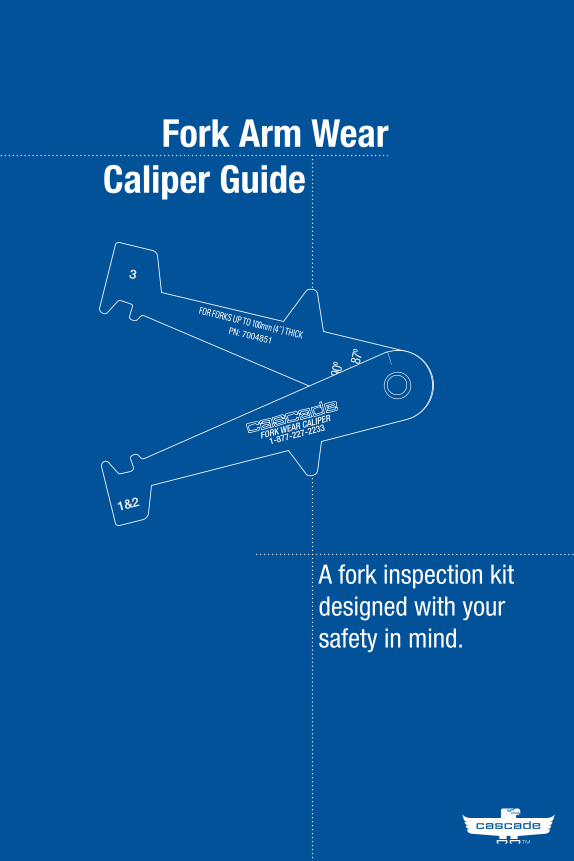
Fork Arm WearCaliper Guide a
A fork inspection kit designed with your safety in mind.
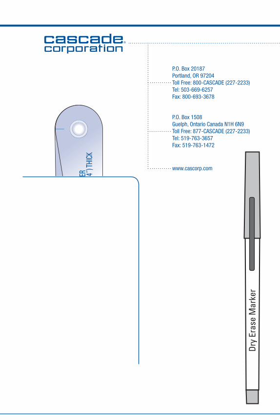
P.O. Box 20187Portland, OR 97204Toll Free: 800-CASCADE (227-2233)Tel: 503-669-6257Fax: 800-693-3678
P.O. Box 1508Guelph, Ontario Canada N1H 6N9Toll Free: 877-CASCADE (227-2233)Tel: 519-763-3657Fax: 519-763-1472
www.cascorp.com
Dry
Eras
e M
arke
r
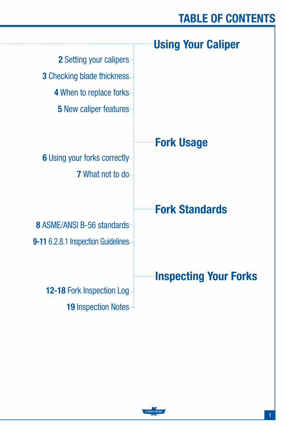
2 Setting your calipers
3 Checking blade thickness
4 When to replace forks
5 New caliper features
1
Fork Usage
Using Your Caliper
TABLE OF CONTENTS
6 Using your forks correctly
7 What not to do
Fork Standards8 ASME/ANSI B-56 standards
9-11 6.2.8.1 Inspection Guidelines
Inspecting Your Forks12-18 Fork Inspection Log
19 Inspection Notes
2
FORK ARM WEAR CALIPER GUIDE
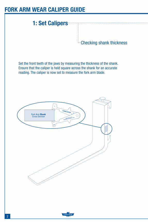
Set the front teeth of the jaws by measuring the thickness of the shank. Ensure that the caliper is held square across the shank for an accurate reading. The caliper is now set to measure the fork arm blade.
1: Set Calipers
Checking shank thickness
Fork Arm ShankCross Section
3
FORK ARM WEAR CALIPER GUIDE
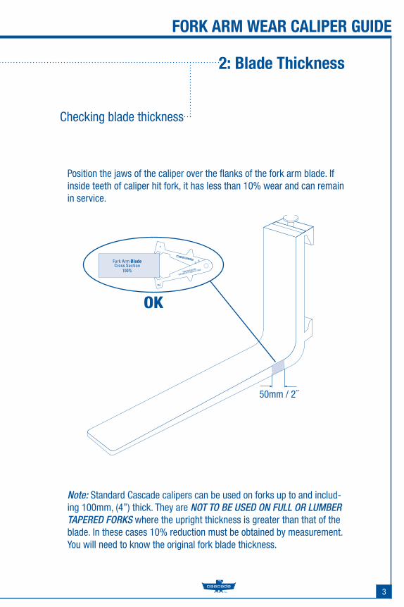
Position the jaws of the caliper over the fl anks of the fork arm blade. If inside teeth of caliper hit fork, it has less than 10% wear and can remain in service.
Note: Standard Cascade calipers can be used on forks up to and includ-ing 100mm, (4”) thick. They are NOT TO BE USED ON FULL OR LUMBER TAPERED FORKS where the upright thickness is greater than that of the blade. In these cases 10% reduction must be obtained by measurement. You will need to know the original fork blade thickness.
Checking blade thickness
2: Blade Thickness
Fork Arm BladeCross Section
100%
50mm / 2˝
OK
4
FORK ARM WEAR CALIPER GUIDE
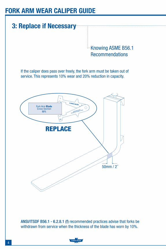
If the caliper does pass over freely, the fork arm must be taken out ofservice. This represents 10% wear and 20% reduction in capacity.
ANSI/ITSDF B56.1 - 6.2.8.1 (f) recommended practices advise that forks be withdrawn from service when the thickness of the blade has worn by 10%.
3: Replace if Necessary
Knowing ASME B56.1Recommendations
50mm / 2˝
REPLACE
Fork Arm BladeCross Section
90%
5
FORK ARM WEAR CALIPER GUIDE
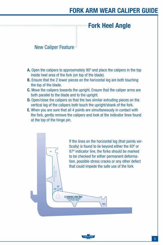
A. Open the calipers to approximately 90º and place the calipers in the top inside heel area of the fork (on top of the blade).
B. Ensure that the 2 lower pieces on the horizontal leg are both touching the top of the blade.
C. Move the calipers towards the upright. Ensure that the caliper arms are both parallel to the blade and to the upright.
D. Open/close the calipers so that the two similar extruding pieces on the vertical leg of the calipers both touch the upright/shank of the fork.
E. When you are sure that all 4 points are simultaneously in contact with the fork, gently remove the calipers and look at the indicator lines found at the top of the hinge pin.
If the lines on the horizontal leg (that points ver-tically) is found to lie beyond either the 93º or 87º indicator line, the forks should be marked to be checked for either permanent deforma-tion, possible stress cracks or any other defect that could impede the safe use of the fork.
Fork Heel Angle
New Caliper Feature
6
FORK ARM WEAR CALIPER GUIDE
1. Inspect forks regularly and use the Cascade inspection log found at the back of this guide.
2. Make sure the fork capacity meets or exceeds truck rated capacity and load weight.
3. Obtain written approval from fork manufacturer prior to making any fork modifi cations/repairs.
4. Determine fork wear cycle and replacement schedule for your opera-tion. Use of larger forks in demanding applications will extend fork life.
5. All positioning locks must be in place at all times. Forks must be properly seated on the carriage and the positioning locks fully located in the slot before use.
Use your forks correctly
Fork Use Guidelines
7
FORK ARM WEAR CALIPER GUIDE
1. Do not overload beyond the rated fork capacity.
2. Do not change fork from one lift truck to another without knowing capacities of each truck and fork.
3. Do not use a fork in an application for which it is not designed.
4. Do not add a fork extension longer than 150% of the supporting fork’s length.
5. Do not try to repair or modify forks in the fi eld, especially by welding. Improper welding destroys heat treat properties and makes the forks brittle.
6. Do not carry full or partial loads on one fork.
7. Do not apply sideways pressure to forks, commonly called “side load-ing” as they are designed for vertical loading only.
Fork Use Guidelines
What not to do
8
FORK ARM WEAR CALIPER GUIDE
6.2.8 Inspection and Repair of Forks in Service on Fork Lift Trucks(a) Forks in use shall be inspected at intervals of not more than 12 months (for single shift operations) or whenever any defect or permanent deforma-tion is detected. Severe applications will require more frequent inspection.(b) Individual Load Rating of Forks. When forks are used in pairs(the normal arrangement), the rated capacity of each fork shall be at least half of the manufacturer’s rated capacity of the truck, and at the rated load center distance shown on the lift truck nameplate.
8
User Fork Wear Standards
ANSI/ITSDF B-56.1 - 2005
9
FORK ARM WEAR CALIPER GUIDE
6.2.8.1 Inspection.Fork inspection shall be carried out carefully by trained personnel with the aim of detecting any damage, failure, deformation, etc., which might impair safe use. Any fork that shows such a defect shall be withdrawn from ser-vice, and shall not be returned to service unless it has been satisfactorily repaired in accordance with para. 6.2.8.2.
(a) Surface Cracks.The fork shall be thoroughly examined visually for cracks and if considered necessary, subjected to a non-destructive crack detection process, special attention being paid to the heel and welds attaching all mounting compo-nents to the fork blank. This inspection for cracks must also include any special mounting mechanisms of the fork blank to the fork carrier including bolt type mountings and forged upper mounting arrangements for hook or shaft type carriages. The forks shall not be returned to service if surface cracks are detected.
(b) Straightness of Blade and Shank.The straightness of the upper face of the blade and the front face of the shank shall be checked. If the deviation from straightness exceeds 0.5% of the length of the blade and/or the height of the shank, respectively, the fork shall not be returned to service until it has been repaired in accordance with para. 6.2.8.2
(c) Fork Angle (Upper Face of Blade to Load Face of the Shank.)Any fork that has a deviation of greater than 3 degrees from the original specifi cation shall not be returned to service. The rejected fork shall be reset and tested in accordance with para. 6.2.8.2.
User Fork Wear Standards
6.2.8.1 Inspection
10
FORK ARM WEAR CALIPER GUIDE
(d) Difference in Height of Fork Tips.The difference in height of one set of forks when mounted on the fork carrier shall be checked. If the difference in tip heights exceeds 3% of the length of the blade, the set of forks shall not be returned to service until repaired in accordance with para. 6.2.8.2.
(e) Positioning Lock (When Originally Provided).It shall be confi rmed that the positioning lock is in good repair and cor-rect working order. If any fault is found, the fork shall be withdrawn from service until satisfactory repairs have been effected.
(f) Wear. (1) Fork Blade and Shank. The fork blade and shank shall be thoroughly checked for wear, special attention being paid to the vicinity of the heel. If the thickness is reduced to 90% of the original thickness, the fork shall not be returned to service (2) Fork Hooks (Where Originally Provided). The support face of the top hook and the retaining faces of both hooks shall be checked for wear, crushing, and other local deformations. If these are apparent to such an extent that the clearance between the fork and the fork carrier becomes excessive, the fork shall not be returned to service until repaired in accordance with para. 6.2.8.2.
(g) Legibility of Marking (When Originally Provided)If the fork marking in accordance with para. 7.27.2 is not clearly legible. It shall be renewed. Marking shall be renewed per instructions from original supplier.
User Fork Wear Standards
6.2.8.1 Inspection (Cont.)
11
FORK ARM WEAR CALIPER GUIDE
(a) Repair.Only the manufacturer of the fork or an expert ofequal competence shall decide if a fork may be repaired for continued use, and the repairs shall only be carried out by such parties.
It is not recommended that surface cracks or wear be repaired by welding. When repairs necessitating resetting are required, the fork shall subse-quently be subjected to an appropriate heat treatment, as necessary.
User Fork Wear Standards
6.2.8.1 Repair & Testing
12
FORK ARM WEAR CALIPER GUIDE
Inspection Date:
Inspected By:
Notes:
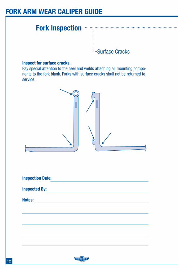
Inspect for surface cracks.Pay special attention to the heel and welds attaching all mounting compo-nents to the fork blank. Forks with surface cracks shall not be returned to service.
Fork Inspection
Surface Cracks
13
FORK ARM WEAR CALIPER GUIDE
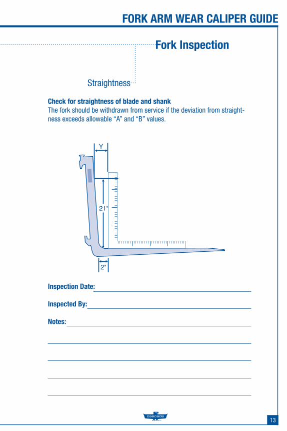
Check for straightness of blade and shankThe fork should be withdrawn from service if the deviation from straight-ness exceeds allowable “A” and “B” values.
Inspection Date:
Inspected By:
Notes:
Fork Inspection
Straightness
2"
Y
21"
14
FORK ARM WEAR CALIPER GUIDE
Inspection Date:
Inspected By:
Notes:
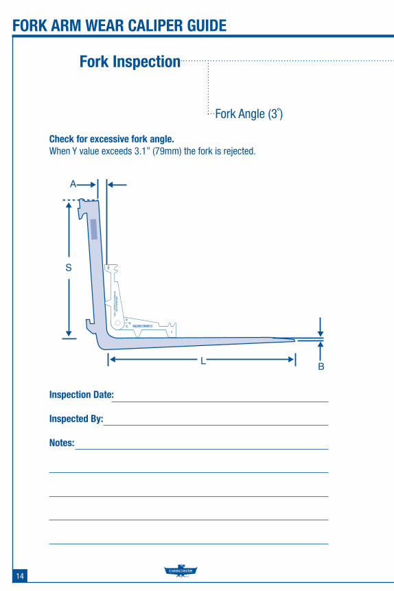
Check for excessive fork angle.When Y value exceeds 3.1” (79mm) the fork is rejected.
Fork Inspection
Fork Angle (3˚)
B
A
S
L
15
FORK ARM WEAR CALIPER GUIDE
B
A
Inspection Date:
Inspected By:
Notes:
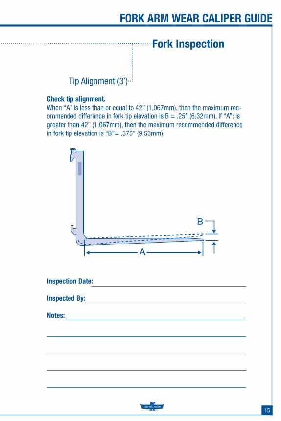
Check tip alignment.When “A” is less than or equal to 42” (1,067mm), then the maximum rec-ommended difference in fork tip elevation is B = .25” (6.32mm). If “A”: is greater than 42” (1,067mm), then the maximum recommended difference in fork tip elevation is “B”= .375” (9.53mm).
Fork Inspection
Tip Alignment (3˚)
16
FORK ARM WEAR CALIPER GUIDE
Inspection Date:
Inspected By:
Notes:
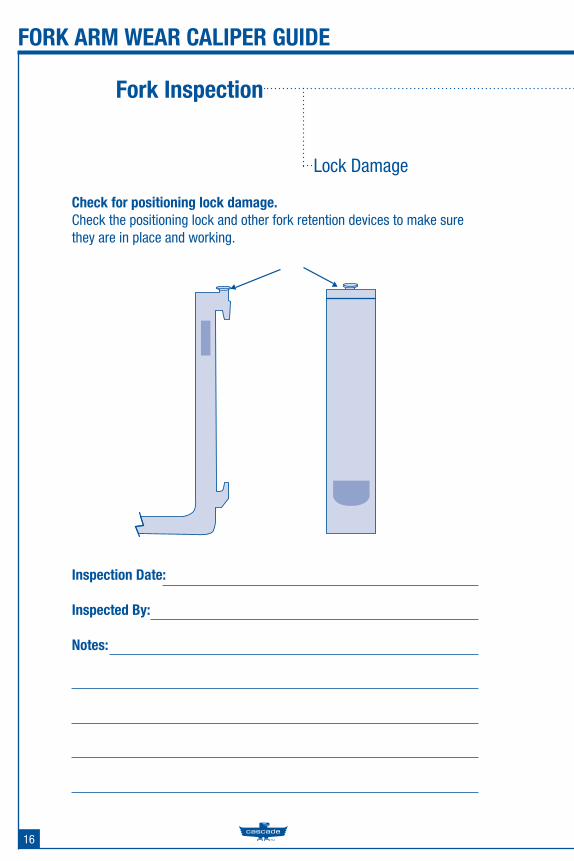
Check for positioning lock damage.Check the positioning lock and other fork retention devices to make sure they are in place and working.
Fork Inspection
Lock Damage
17
FORK ARM WEAR CALIPER GUIDE
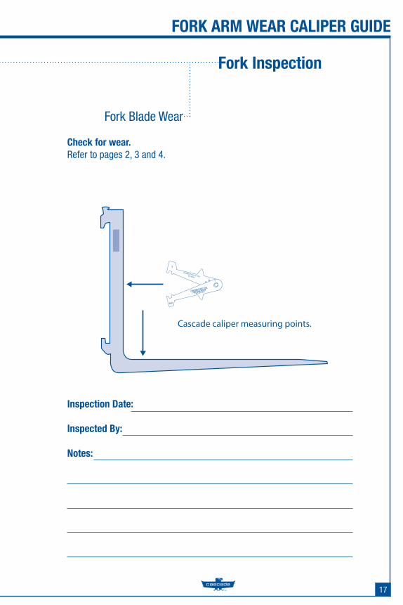
Cascade caliper measuring points.
Inspection Date:
Inspected By:
Notes:
Check for wear.Refer to pages 2, 3 and 4.
Fork Inspection
Fork Blade Wear
18
FORK ARM WEAR CALIPER GUIDE
Inspection Date:
Inspected By:
Notes:
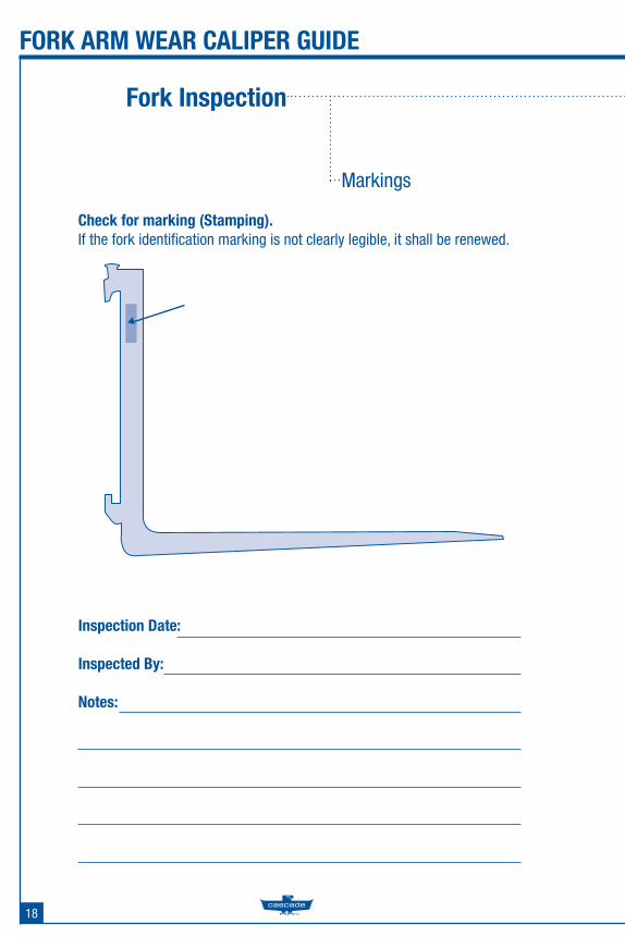
Check for marking (Stamping).If the fork identifi cation marking is not clearly legible, it shall be renewed.
Fork Inspection
Markings

Leading the world in quality m
aterial handling products for lift trucks.For additional Fork CaliperSafety Guides contact yourlift truck dealer.
To reorder call: 1.877.227.2233or visit www.cascorp.com
Cascade is a registered trademarkof Cascade Corporation.©Cascade Corporation 2007.All rights reserved.
Form #1111111 10M CG 11/06
P.O. Box 20187Portland, OR 97204
Toll Free: 800-CASCADE (227-2233)Tel: 503-669-6257Fax: 800-693-3768
P.O. Box 1508Guelph, Ontario Canada N1H 6N9
Toll Free: 877-CASCADE (227-2233)Tel: 519-763-3657Fax: 519-763-1472
www.cascorp.com