Embed Size (px)
Citation preview
FORM 201.24-EG1 (701)
YCWSWATER COOLED LIQUID CHILLER
91 TONS THROUGH 216 TONS320 kW THROUGH 760 kW
60HzSTYLE A
2 YORK INTERNATIONAL
Nomenclature
YC W S 0140 S C 46 Y A
YC= York Chiller
W= Water cooled
S= Screw Compressor
Nominal Capacity in Tons Refrigerant C = R-22
Voltage Code:
Type Start: Y = Star-Delta
Design Series: A
S= Standard Efficiency
17 = 200-3-60
28 = 230-3-60
40 = 380-3-60
46 = 460-3-60
58 = 575-3-60
Table of Contents
Introduction .............................................................................................................................................................. 3Specifications .......................................................................................................................................................... 4Accessories & Options ............................................................................................................................................ 7Design Parameters .................................................................................................................................................. 8Pressure Drops ...................................................................................................................................................... 10Selection Data ....................................................................................................................................................... 12Ratings (R-22 English) ........................................................................................................................................... 14Ratings (R-22 SI) .................................................................................................................................................... 16Ratings- Brine (30 % Ethylene Glycol) (R-22 English) ............................................................................................ 18Ratings- Brine (30 % Ethylene Glycol) (R-22 SI) .................................................................................................... 20Ratings- Brine (30 % Propylene Glycol) (R-22 English) .......................................................................................... 22Ratings- Brine (30 % Propylene Glycol) (R-22 SI) ................................................................................................... 24Part Load Ratings .................................................................................................................................................. 26Physical Data ........................................................................................................................................................ 28Isolator Selection Data ........................................................................................................................................... 29Isolator Details ....................................................................................................................................................... 30Sound Data ............................................................................................................................................................ 31Dimensions (English) ............................................................................................................................................. 32Electrical Data ....................................................................................................................................................... 36Incoming Wire Range Selections............................................................................................................................ 39Customer Wiring Data ............................................................................................................................................ 42Typical Control Panel Wiring .................................................................................................................................. 44Application Data ..................................................................................................................................................... 46Guide Specifications .............................................................................................................................................. 47
FORM 201.24-EG1
3YORK INTERNATIONAL
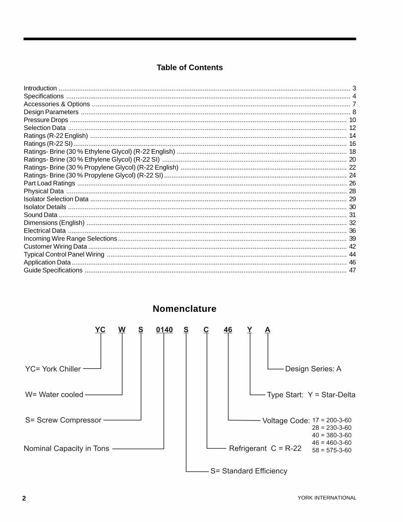
YORK YCWS Water-Cooled models provide chilled water for all air conditioning applications thatuse central station air handling or terminal units. They are completely self-contained and aredesigned for indoor (new or retrofit) installation. Each unit includes accessible semi-hermeticscrew compressors, a liquid cooler, water cooled condenser, and a user-friendly, diagnosticMicrocomputer Control Center all mounted on a rugged steel base. The units are produced at anISO 9001 registered facility. The YCWS chillers have certified ratings in accordance with ARIStandard 550/590.
Introduction
York YCWS Water Cooled Screw Chillers
4 YORK INTERNATIONAL
GENERAL
The Liquid Chiller will be completely assembled with allinterconnecting refrigerant piping and internal wiring,ready for field installation.
The unit will be pressure-tested, evacuated, and chargedwith Refrigerant-22, and York ‘L’ (POE) synthetic oil.There will be an operational test, with water flowingthrough the cooler, to check that each control deviceoperates correctly.
The unit will be covered with a coat of Caribbean Blueenamel. Units are designed in accordance with NFPA70 (National Electric Code), U.L. and cU.L. Standards,ASHRAE/ANSI 15 Safety Code for Mechanical Refrig-eration. All units are produced at an ISO 9001 regis-tered facility. All YCWS chillers are rated and certified inaccordance with ARI Standard 550/590 at ARI condi-tions.
SEMI-HERMETIC YORK SCREW COMPRESSORS
• Continuous function, microprocessor controlled, 3- wayproportional Capacity Control Valve provides regulatedoutput pressure independent of valve input pressurefor a stable, smooth, and precise match of compres-sor capacity to cooling load to 10% of chiller capacity.
• Automatic spring return of capacity control valve tominimum load position ensures compressor startingat minimum motor load. Internal discharge check toprevent rotor backspin upon shutdown.
• Acoustically tuned, internal discharge gas path elimi-nates objectionable noise at the source, while optimiz-ing flow for maximum performance.
• Reliable suction gas cooled, high efficiency, acces-sible hermetic motor with APT2000 type magnet wireand redundant overload protection using both ther-mistor and current overload protection.
• Suction gas screen and serviceable, 0.5 micron fullflow oil filter within the compressor housing.
• Cast iron compressor housing precisely machined foroptimal clearances and superb efficiency. Entire com-pressor, from suction to discharge has a Design Work-ing Pressure of 450psig (31 bar).
• 350W compressor body cartridge heater.
• Each compressor will be mounted on isolator pads toreduce transmission of vibration to the rest of the unit.
COOLER
The dual-circuit cooler will be the direct-expansion type,with refrigerant in the tubes and chilled liquid flowingthrough the baffled shell. The design working pressureof the shell (liquid) side will be 150 PSIG (10.3 bar), and300 PSIG (26.7 bar) for the tube (refrigerant) side.
The cooler will be constructed and tested in accordancewith the applicable sections of the ASME Pressure Ves-sel Code, Section VlII, Division (1). The water side willbe exempt per paragraph U-1, (c)(6).
The water baffles will be constructed of galvanized steelto resist corrosion. The removable heads will allow ac-cess to the internally enhanced, seamless, copper tubes.Vent and drain connections will be included.
The cooler will be covered with 3/4" (19.1 mm ) flexible,closed-cell, foam insulation (K = 0.25).
CONDENSERThe condenser is a cleanable thru-tube type with steelshell, copper tubes, removable water heads, and includesintegral subcooling. Refer to PHYSICAL DATA for de-sign working pressures. The shell will be constructedand tested in accordance with section Vll, division 1 ofthe ASME pressure-vessel code. The water side is ex-empt per paragraph U-1 (c) of section VlII, division 1 ofthe ASME pressure-vessel code. The condenser isequipped with relief valves and will hold the full refriger-ant charge for pumpdown.
REFRIGERANT CIRCUITTwo independent refrigerant circuits will be furnished oneach unit. All piping will be copper with brazed joints.The liquid line will include: a shutoff valve with chargingport; sightglass with moisture indicator; thermal expan-sion valve; solenoid valve; and high-absorption remov-able-core filter drier. The entire suction line and the liq-uid line between the expansion valve and the cooler willbe insulated with flexible, closed-cell, foam insulation.
POWER AND CONTROL PANELSAll controls and motor starting equipment necessary forunit operation shall be factory wired and function tested.The panel enclosures shall be designed to NEMA 1 (IP32) and manufactured from powder-painted galvanizedsteel.
Specifications
FORM 201.24-EG1
5YORK INTERNATIONAL
The Power and Control Panel shall be divided into a powersection for each electrical system, a common input sec-tion and a control section.
Each power panel shall contain:
Compressor starting contactors, control circuitserving compressor capacity control, compressorcontactor coils and compressor motor overloads. Thecompressor motor overloads contain current trans-formers which sense each phase, as an input to themicroprocessor, to protect the compressor motorsfrom damage due to: low input current, high input cur-rent, unbalanced current, single phasing, phasereversal, and compressor locked rotor.
The common input section shall contain:The control supply transformer providing 115V, cus-tomer relay board and control circuit switch discon-nect/emergency stop device.
The control section shall contain:On/Off rocker switch, microcomputer keypad and dis-play, microprocessor board, I/O expansion board,relay boards, and 24V fused power supply board.
MICROPROCESSOR CONTROLSFuzzy Logic control will be incorporated in the YCWSrange of chillers. Fuzzy Logic allows the control systemto monitor several key variables to provide tighter, morestable chilled water temperature control. The control sys-tem monitors the leaving chilled water temperature totrack where it has been, where it is now, how fast it ismoving, and accurately adjusts the chiller operation inanticipation of expected performance to minimize hunt-ing and save energy.
The microprocessor shall have the following functionsand displays:
• A liquid crystal 40 character display with text providedon two lines and light emitting diode backlighting foroutdoor viewing.
• A color-coded, 35 button, sealed keypad with sec-tions for Display, Entry, Setpoints, Clock, Print, Pro-gram, and Unit On/Off Switch.
The standard controls shall include: brine chilling or ther-mal storage, automatic pumpdown, run signal contacts,demand load limit from external building automation sys-tem input, remote reset liquid temperature reset input,unit alarm contacts, chilled liquid pump control, automatic
reset after power failure, automatic system optimizationto match operating conditions, software stored in non-volatile memory (EPROM) to eliminate chiller failure dueto AC power failure.
The microprocessor can be directly connected to a YORKISN Building Automation System via the standard on-board RS485 communications port. This option also pro-vides open system compatibility with other communica-tions networks.
Programmed Setpoints shall be retained in a lithium bat-tery backed RTC with a memory of five years.
Display - In Imperial (°F and PSIG) or SI (°C and BAR)units, and for each circuit:
• Return and leaving chilled liquid• Day, date and time. Daily start/stop times. Holiday
and Manual Override status.• Compressor operating hours and starts. Automatic
or manual lead/lag. Lead compressor identification.• Run permissive status. No cooling load condition.
Compressor run status.• Anti-recycle timer and anti-coincident start timer sta-
tus per compressor.• Suction (and suction superheat), discharge, and oil
pressures and temperatures per System.• Percent full load compressor motor current per phase
and average per phase. Compressor capacity con-trol valve input steps.
• Cutout status and setpoints for: supply fluid tempera-ture, low suction pressure, high discharge pressureand temperature, high oil temperature, low and highcurrent, phase rotation safety, and low leaving liquidtemperature.
• Unloading limit setpoints for high discharge pressureand compressor motor current.
• Liquid pull-down rate sensitivity (0.5°F to 5°F [0.3°Cto 3.0°C]/minute in 0.1°F [0.05°C] increments).
• Status of: evaporator heater, load and unload timers,chilled water pump.
• Out of range message.• Up to 6 fault shut down conditions.• Standard Display Language is English, with an Op-
tion for Spanish.
Entry - Enter set point changes, cancel inputs, advanceday, change AM/PM.Set Points - Chilled liquid temperature, chilled liquidrange, remote reset temperature range.Clock - Time, daily or holiday start/stop schedule, manual
6 YORK INTERNATIONAL
override for servicing.Print - Operating data or system fault shutdown historyfor last six faults. Printouts through an RS-232 port via aseparate printer (by others).Program -• Low leaving liquid temperature cutout, 300 to 600
second anti-recycle timer, lag compressor start timedelay, and average motor current unload point. Liq-uid temperature setpoint reset signal from YORK ISNor building automation system (by others) via:
• Pulse width modulated (PWM) input for up to 40°F(22°C) total reset as standard.
• Optional Building Automation System interface inputcard for up to 20°F (11.1°C) reset using a: 4 to 20mA, 0 to 10 Vdc input, or discrete reset input.
• NOTE: The Standard MicroPanel can be directly con-nected to a YORK ISN Building Automation System
Specifications (Continued)
via the standard onboard RS485 communication port.This Option also provides open system compatibilitywith other communications networks (BACnet™ &LONMARK™ via interface through standard onboard485 or 232 port and an external YorkTalk Translator.
• Additional functions (password protected) for program-ming by a qualified service technician:
Cutouts for low suction pressure, high dischargepressure, high oil temperature.
Refrigerant type.
High discharge pressure unload setpoint.
Compressor motor current percent limit.
FORM 201.24-EG1
7YORK INTERNATIONAL
ALTERNATIVE REFRIGERANTS - Contact your nearest YORK of-fice for information and availability on alternative HFC refrigerants.
ELECTRICAL OPTIONS:MULTIPLE POINT POWER SUPPLY CONNECTION -Standard field power wiring connection on all models is MultiplePoint Power Connection to factory provided Terminal Blocks. Twofield supplied electrical power circuits with appropriate branch cir-cuit protection provide power to each of two motor control centercabinets, located on either side of the Control panel on the front ofthe chiller. Each cabinet contains starter elements for one com-pressor.
Optional to the Terminal Blocks for field power connection areNon-Fused Disconnects or Circuit Breaker Switches with external,lockable handles.
SINGLE POINT POWER CONNECTION - (Factory Mounted) Anoptional configuration for field connection of a single electrical cir-cuit to: either Terminal Block or Non-Fused Disconnect Switch withlockable external handle (in compliance with Article 440 of N.E.C.,to isolate unit power supply for service). Factory wiring is pro-vided from the Terminal Block or Disconnect Switch to Factorysupplied individual system Circuit Breakers, Non-Fused Disconnectswitch with external, lockable handle or J Class Fuses/Fuse Blockin each of the two compressor motor control centers. (Note: SinglePoint Non-Fused Disconnect Switch will not be supplied with indi-vidual system Non Fused Disconnect Switches with external, lock-able handles in each of the two compressor motor control cen-ters).
65 Ka HIGH VOLTAGE PROTECTION - Non-Fused DisconnectSwitch with fuses (200 & 575V) or Circuit Breakers (230, 380, &460V) are used for applications where customers have a require-ment for single point wiring with high “fault current” withstandingcapability. This option provides between 50Ka and 65Ka withstandprotection to the equipment.
BUILDING AUTOMATION SYSTEM INTERFACE (FactoryMounted) – Provides means to reset the leaving chilled liquidtemperature or percent full load amps (current limiting) from theBAS (Factory Mounted):
• Printed circuit board to accept 4 to 20 milliamp, 0 to 10 VDC,or dry contact closure input from the BAS.
• A YORK ISN Building Automation System can provide a PulseWidth Modulated (PWM) signal direct to the standard controlpanel via the standard onboard RS485 port.
FLOW SWITCH – The flow switch or its equivalent must be fur-nished with each unit. 150 PSIG (10.5 bar) DWP – For standardunits. Johnson Controls model F61MG-1C Vapor-proof SPDT, NEMA4X switch (150 PSIG [10.5 bar] DWP), -20°F to 250°F- (29°C to121°C), with 1" NPT connection for upright mounting in horizontalpipe. (Field mounted)
DIFFERENTIAL PRESSURE SWITCH - Alternative to the above men-tioned Flow Switch. Pretemco Model DPS 300A-P4OPF-82582-S(20.7bar max working pressure). SPDT 5 amp 125/250 VAC switch.Range: 0 - 2.8bar, deadband: 0.003 - 0.005bar, with 1/4 NPTE pres-sure connections.
LANGUAGE LCD AND KEYPAD - Standard display language and
keypad is in English. Spanish is available as an option.
PRINTER KIT - Printer for obtaining printout of unit operating andhistory data. (Field Mounted)
MULTIPLE UNIT SEQUENCE CONTROL (Field Mounted) - Se-quencing Control with automatic unit sequencing. Necessary itemsfor operation and control of up to eight units with parallel watercircuits. Includes software and mixed liquid temperature sensor(interconnecting wiring by others).
PRESSURE VESSEL CODES - Coolers and condensers can besupplied in conformance with the following pressure codes:A.S.M.E. (Standard)
CHICAGO CODE RELIEF VALVES (Factory Mounted) - Unit will beprovided with relief valves to meet Chicago Code requirements.
ACCESSORIES:FLANGES (Weld Type) – Consists of 150 PSI (10.5 bar ) standardcooler (150 lb) R.F. flanges to convert to flanged cooler-connec-tions and includes companion flanges. (Field mounted)
FLANGES (Victaulic Type) – Consists of (2) Flange adapter forgrooved end pipe (standard 150 PSI [10.5 bar] cooler). Includescompanion flanges. (Field mounted)
VIBRATION ISOLATION:• Neoprene Isolators – Recommended for normal installations.
Provides very good performance in most applications for theleast cost. (Field mounted)
• 1" Spring Isolators – Level adjustable, spring and cage typeisolators for mounting under the unit base rails. 1" nominal de-flection may vary slightly by application. (Field mounted)
• 2" Seismic Spring Isolators – Restrained Spring-Flex Mountingsincorporate a rugged welded steel housing with vertical andhorizontal limit stops. Housings designed to withstand a mini-mum 1.0g accelerated force in all directions to 2". Level adjust-able, deflection may vary slightly by application. (Field-mounted)
ALTERNATIVE CHILLED FLUID APPLICATIONS:Standard water chilling application range is 40°F to 50°F (4.4°C to10°C) Leaving Chilled Water Temperature. To protect against nui-sance safety trips below 40°F (4.4°C) and reduce the possibility ofcooler damage due to freezing during chiller operation, the unitmicroprocessor automatically unloads the compressors at abnor-mally low suction temperature (pressure) conditions , prior to safetyshutdown.
• Process Brine Option – Process or other applications requir-ing chilled fluid below 40°F (4.4°C) risk water freezing in theevaporator, typically overcome by using antifreeze. For theseapplications, the chiller system incorporates brine (ethylene orpropylene glycol solution), and the system design Leaving ChilledFluid Temperature must be provided on the order form to ensureproper factory configuration.
• Thermal Storage Option – Thermal Storage equires specialcapabilities from a chiller, including the ability to ‘charge’ an icestorage tank, then possibly automatically reset for operation atelevated Leaving Chilled Fluid Temperatures as required by au-tomatic building controls. The Thermal Storage Option providesIce Storage duty Leaving Chilled Fluid setpoints from 25°F to15°F( -4°C to -10°C) minimum during charge cycle, with a Resetrange of 36°F (20°C) supply fluid temperature.
Accessories & Options
8 YORK INTERNATIONAL
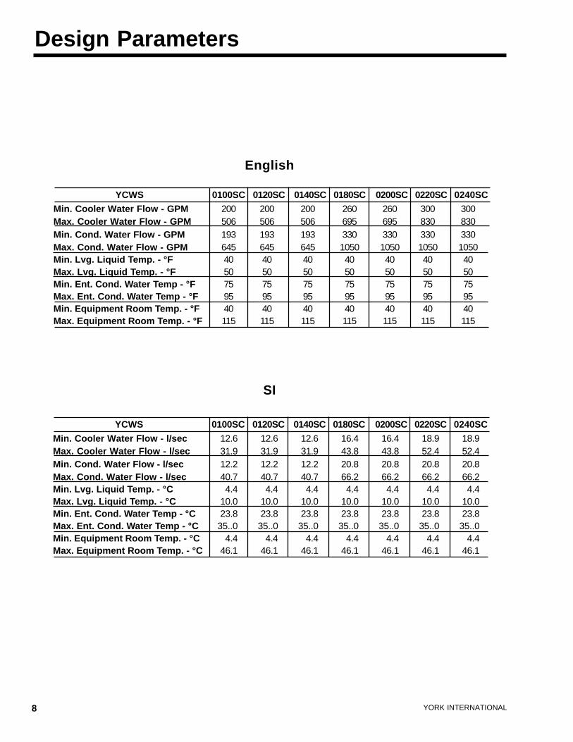
Design Parameters
Min. Cooler Water Flow - l/sec 12.6 12.6 12.6 16.4 16.4 18.9 18.9Max. Cooler Water Flow - l/sec 31.9 31.9 31.9 43.8 43.8 52.4 52.4Min. Cond. Water Flow - l/sec 12.2 12.2 12.2 20.8 20.8 20.8 20.8Max. Cond. Water Flow - l/sec 40.7 40.7 40.7 66.2 66.2 66.2 66.2Min. Lvg. Liquid Temp. - °C 4.4 4.4 4.4 4.4 4.4 4.4 4.4Max. Lvg. Liquid Temp. - °C 10.0 10.0 10.0 10.0 10.0 10.0 10.0Min. Ent. Cond. Water Temp - °C 23.8 23.8 23.8 23.8 23.8 23.8 23.8Max. Ent. Cond. Water Temp - °C 35..0 35..0 35..0 35..0 35..0 35..0 35..0Min. Equipment Room Temp. - °C 4.4 4.4 4.4 4.4 4.4 4.4 4.4Max. Equipment Room Temp. - °C 46.1 46.1 46.1 46.1 46.1 46.1 46.1
YCWS 0100SC 0120SC 0140SC 0180SC 0200SC 0220SC 0240SC
SI
Min. Cooler Water Flow - GPM 200 200 200 260 260 300 300Max. Cooler Water Flow - GPM 506 506 506 695 695 830 830Min. Cond. Water Flow - GPM 193 193 193 330 330 330 330Max. Cond. Water Flow - GPM 645 645 645 1050 1050 1050 1050Min. Lvg. Liquid Temp. - °F 40 40 40 40 40 40 40Max. Lvg. Liquid Temp. - °F 50 50 50 50 50 50 50Min. Ent. Cond. Water Temp - °F 75 75 75 75 75 75 75Max. Ent. Cond. Water Temp - °F 95 95 95 95 95 95 95Min. Equipment Room Temp. - °F 40 40 40 40 40 40 40Max. Equipment Room Temp. - °F 115 115 115 115 115 115 115
YCWS 0100SC 0120SC 0140SC 0180SC 0200SC 0220SC 0240SC
English
FORM 201.24-EG1
9YORK INTERNATIONAL
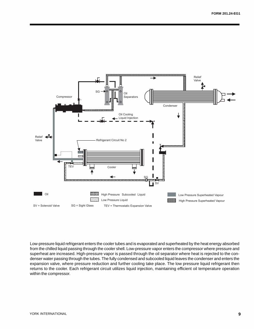
Low-pressure liquid refrigerant enters the cooler tubes and is evaporated and superheated by the heat energy absorbedfrom the chilled liquid passing through the cooler shell. Low-pressure vapor enters the compressor where pressure andsuperheat are increased. High-pressure vapor is passed through the oil separator where heat is rejected to the con-denser water passing through the tubes. The fully condensed and subcooled liquid leaves the condenser and enters theexpansion valve, where pressure reduction and further cooling take place. The low pressure liquid refrigerant thenreturns to the cooler. Each refrigerant circuit utilizes liquid injection, maintaining efficient oil temperature operationwithin the compressor.
High Pressure Superheated Vapour
High Pressure Subcooled Liquid
Low Pressure Liquid
Oil Low Pressure Superheated Vapour
SV = Solenoid Valve SG = Sight Glass TEV = Thermostatic Expansion Valve
Refrigerant Circuit No 2
SV
Oil
Separators
SG
Compressor
Cooler
Condenser
Oil Cooling
Liquid Injection
TEV
SG
ReliefValve
ReliefValve
10 YORK INTERNATIONAL
1
10
100
100 1000 10000
1
10
100
100 1000
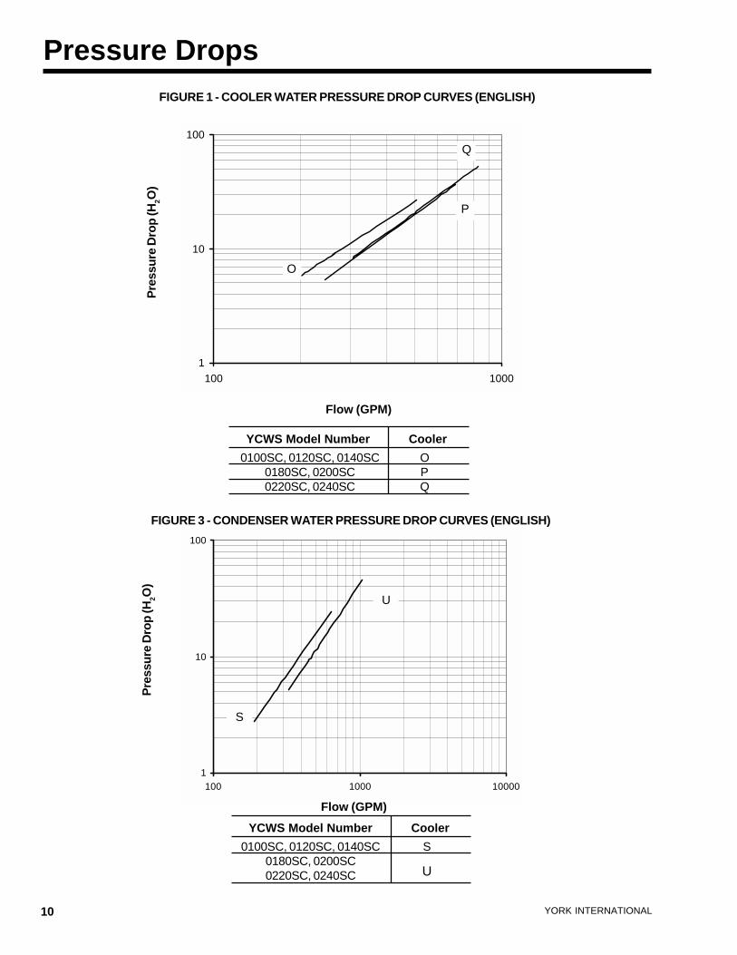
Pressure DropsFIGURE 1 - COOLER WATER PRESSURE DROP CURVES (ENGLISH)
YCWS Model Number Cooler
0100SC, 0120SC, 0140SC0180SC, 0200SC0220SC, 0240SC
OPQ
YCWS Model Number Cooler
FIGURE 3 - CONDENSER WATER PRESSURE DROP CURVES (ENGLISH)
Pre
ssu
re D
rop
(H2O
)
Flow (GPM)
Pre
ssu
re D
rop
(H2O
)
Flow (GPM)
U
S
O
P
Q
0100SC, 0120SC, 0140SC0180SC, 0200SC0220SC, 0240SC
S
U
FORM 201.24-EG1
11YORK INTERNATIONAL
1
10
100
1000
10 100
1
10
100
1000
10 100
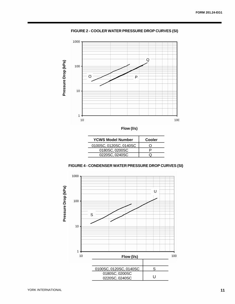
FIGURE 2 - COOLER WATER PRESSURE DROP CURVES (SI)
YCWS Model Number Cooler
0100SC, 0120SC, 0140SC0180SC, 0200SC0220SC, 0240SC
OPQ
FIGURE 4 - CONDENSER WATER PRESSURE DROP CURVES (SI)
Pre
ssu
re D
rop
(kP
a)
Flow (l/s)
S
U
Pre
ssu
re D
rop
(kP
a)
Flow (l/s)
Q
PO
0100SC, 0120SC, 0140SC0180SC, 0200SC0220SC, 0240SC
S
U
12 YORK INTERNATIONAL
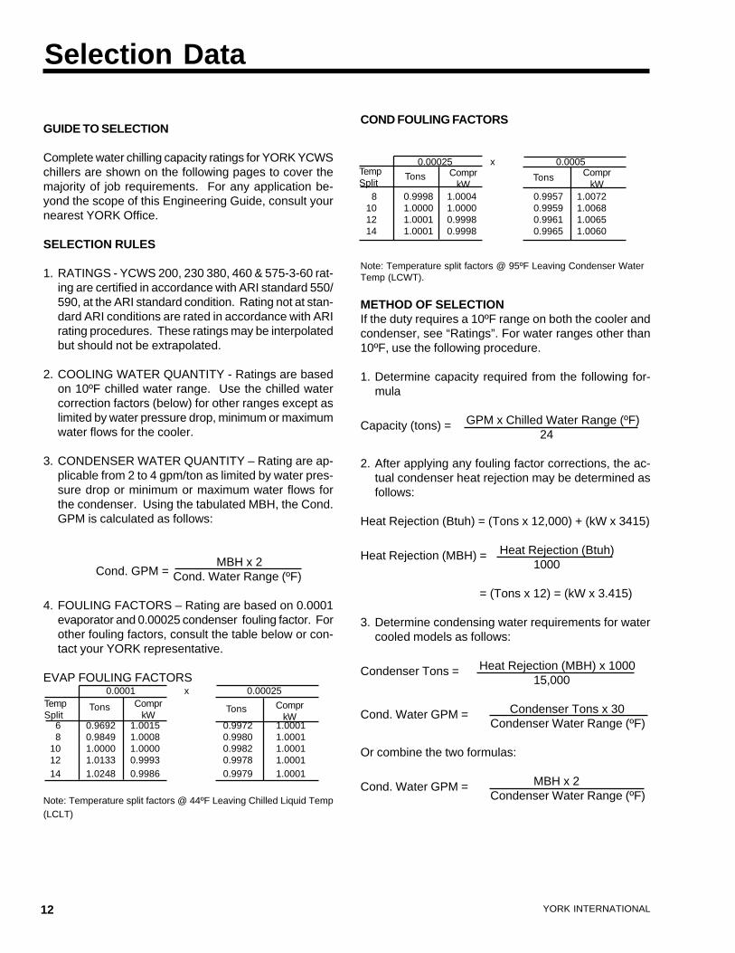
GUIDE TO SELECTION
Complete water chilling capacity ratings for YORK YCWSchillers are shown on the following pages to cover themajority of job requirements. For any application be-yond the scope of this Engineering Guide, consult yournearest YORK Office.
SELECTION RULES
1. RATINGS - YCWS 200, 230 380, 460 & 575-3-60 rat-ing are certified in accordance with ARI standard 550/590, at the ARI standard condition. Rating not at stan-dard ARI conditions are rated in accordance with ARIrating procedures. These ratings may be interpolatedbut should not be extrapolated.
2. COOLING WATER QUANTITY - Ratings are basedon 10ºF chilled water range. Use the chilled watercorrection factors (below) for other ranges except aslimited by water pressure drop, minimum or maximumwater flows for the cooler.
3. CONDENSER WATER QUANTITY – Rating are ap-plicable from 2 to 4 gpm/ton as limited by water pres-sure drop or minimum or maximum water flows forthe condenser. Using the tabulated MBH, the Cond.GPM is calculated as follows:
Cond. GPM =
MBH x 2Cond. Water Range (ºF)
4. FOULING FACTORS – Rating are based on 0.0001evaporator and 0.00025 condenser fouling factor. Forother fouling factors, consult the table below or con-tact your YORK representative.
EVAP FOULING FACTORS 0.0001 x 0.00025
6 0.9692 1.0015 0.9972 1.00018 0.9849 1.0008 0.9980 1.0001
10 1.0000 1.0000 0.9982 1.000112 1.0133 0.9993 0.9978 1.000114 1.0248 0.9986 0.9979 1.0001
Note: Temperature split factors @ 44ºF Leaving Chilled Liquid Temp(LCLT)
Selection Data
COND FOULING FACTORS
0.00025 x 0.0005
8 0.9998 1.0004 0.9957 1.0072 10 1.0000 1.0000 0.9959 1.0068 12 1.0001 0.9998 0.9961 1.0065 14 1.0001 0.9998 0.9965 1.0060
Note: Temperature split factors @ 95ºF Leaving Condenser WaterTemp (LCWT).
METHOD OF SELECTIONIf the duty requires a 10ºF range on both the cooler andcondenser, see “Ratings”. For water ranges other than10ºF, use the following procedure.
1. Determine capacity required from the following for-mula
GPM x Chilled Water Range (ºF)Capacity (tons) = 24
2. After applying any fouling factor corrections, the ac-tual condenser heat rejection may be determined asfollows:
Heat Rejection (Btuh) = (Tons x 12,000) + (kW x 3415)
Heat Rejection (Btuh)Heat Rejection (MBH) =1000
= (Tons x 12) = (kW x 3.415)
3. Determine condensing water requirements for watercooled models as follows:
Heat Rejection (MBH) x 1000Condenser Tons =15,000
Condenser Tons x 30Cond. Water GPM =Condenser Water Range (ºF)
Or combine the two formulas:
MBH x 2Cond. Water GPM =Condenser Water Range (ºF)
TempSplit
Tons ComprkW
Tons ComprkW
TempSplit
Tons ComprkW
Tons ComprkW
FORM 201.24-EG1
13YORK INTERNATIONAL
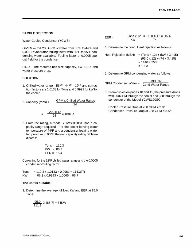
SAMPLE SELECTION
Water Cooled Condenser (YCWS)
GIVEN – Chill 200 GPM of water from 56ºF to 44ºF and0.0001 evaporator fouling factor with 85ºF to 95ºF con-densing water available. Fouling factor of 0.0005 spe-cial field for the condenser.
FIND – The required unit size capacity, kW, EER, andwater pressure drop.
SOLUTION:
1. Chilled water range = 56ºF - 44ºF = 12ºF and correc-tion factors are 1.0133 for Tons and 0.9993 for kW forthe cooler.
GPM x Chilled Water Range2. Capacity (tons) = 24
=
200 x 12 = 100TR 24
2. From the rating, a model YCWS0120SC has a ca-pacity range required. For the cooler leaving watertemperature of 44ºF and a condenser leaving watertemperature of 95ºF, the unit capacity rating table in-dicates:
Tons = 110.3KW = 86.2EER = 15.4
Correcting for the 12ºF chilled water range and the 0.0005condenser-fouling factor:
Tons = 110.3 x 1.0133 x 0.9961 = 111.3TRKW = 86.2 x 0.9993 x 1.0065 = 86.7
The unit is suitable.
3. Determine the average full load kW and EER at 95.0Tons
95.0 X (86.7) = 74KW111.3
Tons x 12 = 95.0 X 12 = 15.4EER = Kw 74
4. Determine the cond. Heat rejection as follows:
Heat Rejection (MBH) = (Tons x 12) + (kW x 3.415)= (95.0 x 12) + (74 x 3.415)= 1140 + 253= 1393
5. Determine GPM condensing water as follows:
GPM Condenser Water = MBH x2
Cond Water Range
6. From curves on pages 10 and 11, the pressure dropswith 200GPM through the cooler and 288 through thecondenser of the Model YCWS120SC
Cooler Pressure Drop at 200 GPM = 2.9ftCondenser Pressure Drop at 288 GPM = 5.5ft
14 YORK INTERNATIONAL
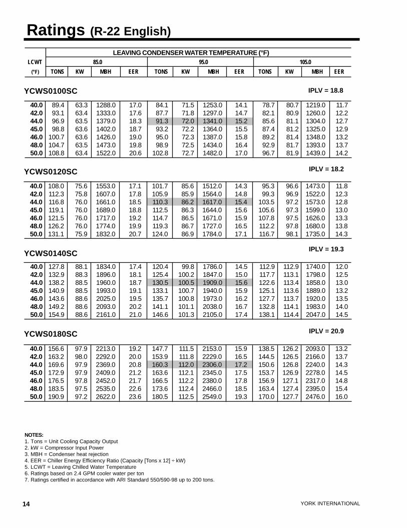
Ratings (R-22 English)
NOTES:1. Tons = Unit Cooling Capacity Output2. kW = Compressor Input Power3. MBH = Condenser heat rejection4. EER = Chiller Energy Efficiency Ratio (Capacity [Tons x 12] ÷ kW)5. LCWT = Leaving Chilled Water Temperature6. Ratings based on 2.4 GPM cooler water per ton7. Ratings certified in accordance with ARI Standard 550/590-98 up to 200 tons.
YCWS0120SC
YCWS0140SC
YCWS0180SC
IPLV = 18.8
IPLV = 18.2
IPLV = 19.3
IPLV = 20.9
YCWS0100SC
LEAVING CONDENSER WATER TEMPERATURE (°F)LCWT 85.0 95.0 105.0
(°F) TONS KW MBH EER TONS KW MBH EER TONS KW MBH EER
40.0 89.4 63.3 1288.0 17.0 84.1 71.5 1253.0 14.1 78.7 80.7 1219.0 11.742.0 93.1 63.4 1333.0 17.6 87.7 71.8 1297.0 14.7 82.1 80.9 1260.0 12.244.0 96.9 63.5 1379.0 18.3 91.3 72.0 1341.0 15.2 85.6 81.1 1304.0 12.745.0 98.8 63.6 1402.0 18.7 93.2 72.2 1364.0 15.5 87.4 81.2 1325.0 12.946.0 100.7 63.6 1426.0 19.0 95.0 72.3 1387.0 15.8 89.2 81.4 1348.0 13.248.0 104.7 63.5 1473.0 19.8 98.9 72.5 1434.0 16.4 92.9 81.7 1393.0 13.750.0 108.8 63.4 1522.0 20.6 102.8 72.7 1482.0 17.0 96.7 81.9 1439.0 14.2
40.0 108.0 75.6 1553.0 17.1 101.7 85.6 1512.0 14.3 95.3 96.6 1473.0 11.842.0 112.3 75.8 1607.0 17.8 105.9 85.9 1564.0 14.8 99.3 96.9 1522.0 12.344.0 116.8 76.0 1661.0 18.5 110.3 86.2 1617.0 15.4 103.5 97.2 1573.0 12.845.0 119.1 76.0 1689.0 18.8 112.5 86.3 1644.0 15.6 105.6 97.3 1599.0 13.046.0 121.5 76.0 1717.0 19.2 114.7 86.5 1671.0 15.9 107.8 97.5 1626.0 13.348.0 126.2 76.0 1774.0 19.9 119.3 86.7 1727.0 16.5 112.2 97.8 1680.0 13.850.0 131.1 75.9 1832.0 20.7 124.0 86.9 1784.0 17.1 116.7 98.1 1735.0 14.3
40.0 127.8 88.1 1834.0 17.4 120.4 99.8 1786.0 14.5 112.9 112.9 1740.0 12.042.0 132.9 88.3 1896.0 18.1 125.4 100.2 1847.0 15.0 117.7 113.1 1798.0 12.544.0 138.2 88.5 1960.0 18.7 130.5 100.5 1909.0 15.6 122.6 113.4 1858.0 13.045.0 140.9 88.5 1993.0 19.1 133.1 100.7 1940.0 15.9 125.1 113.6 1889.0 13.246.0 143.6 88.6 2025.0 19.5 135.7 100.8 1973.0 16.2 127.7 113.7 1920.0 13.548.0 149.2 88.6 2093.0 20.2 141.1 101.1 2038.0 16.7 132.8 114.1 1983.0 14.050.0 154.9 88.6 2161.0 21.0 146.6 101.3 2105.0 17.4 138.1 114.4 2047.0 14.5
40.0 156.6 97.9 2213.0 19.2 147.7 111.5 2153.0 15.9 138.5 126.2 2093.0 13.242.0 163.2 98.0 2292.0 20.0 153.9 111.8 2229.0 16.5 144.5 126.5 2166.0 13.744.0 169.6 97.9 2369.0 20.8 160.3 112.0 2306.0 17.2 150.6 126.8 2240.0 14.345.0 172.9 97.9 2409.0 21.2 163.6 112.1 2345.0 17.5 153.7 126.9 2278.0 14.546.0 176.5 97.8 2452.0 21.7 166.5 112.2 2380.0 17.8 156.9 127.1 2317.0 14.848.0 183.5 97.5 2535.0 22.6 173.6 112.4 2466.0 18.5 163.4 127.4 2395.0 15.450.0 190.9 97.2 2622.0 23.6 180.5 112.5 2549.0 19.3 170.0 127.7 2476.0 16.0
FORM 201.24-EG1
15YORK INTERNATIONAL
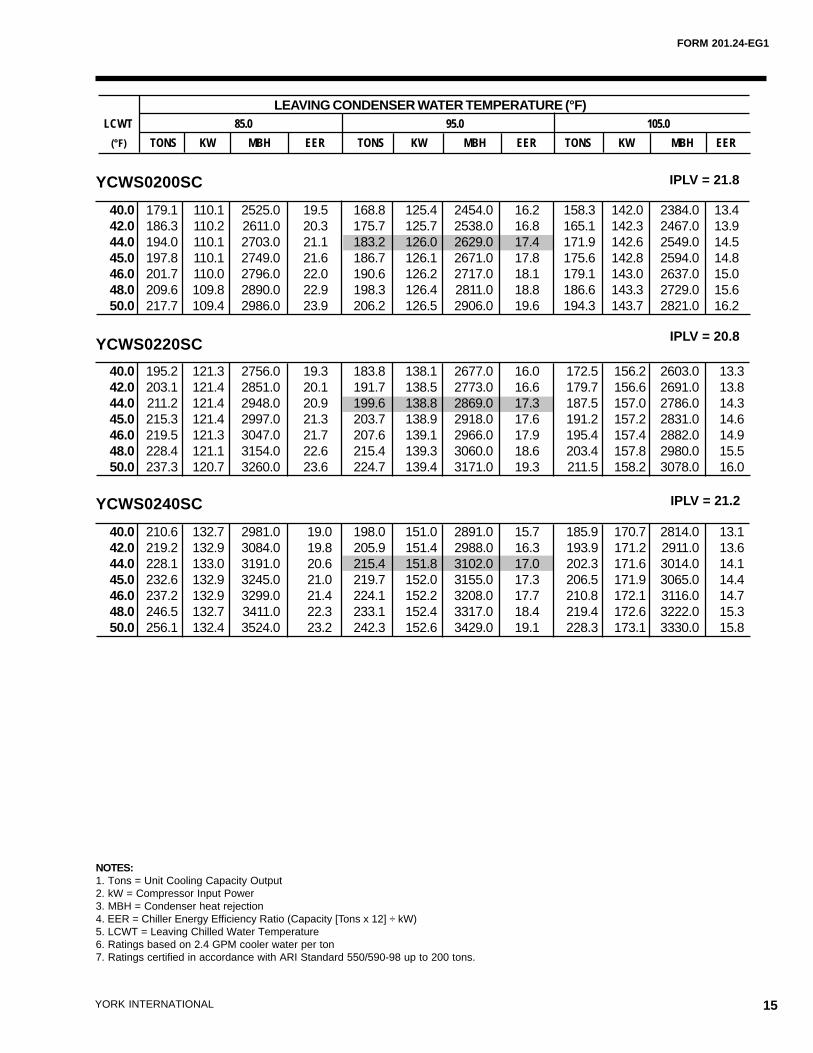
YCWS0200SC
YCWS0220SC
YCWS0240SC
IPLV = 21.8
IPLV = 20.8
IPLV = 21.2
NOTES:1. Tons = Unit Cooling Capacity Output2. kW = Compressor Input Power3. MBH = Condenser heat rejection4. EER = Chiller Energy Efficiency Ratio (Capacity [Tons x 12] ÷ kW)5. LCWT = Leaving Chilled Water Temperature6. Ratings based on 2.4 GPM cooler water per ton7. Ratings certified in accordance with ARI Standard 550/590-98 up to 200 tons.
40.0 179.1 110.1 2525.0 19.5 168.8 125.4 2454.0 16.2 158.3 142.0 2384.0 13.442.0 186.3 110.2 2611.0 20.3 175.7 125.7 2538.0 16.8 165.1 142.3 2467.0 13.944.0 194.0 110.1 2703.0 21.1 183.2 126.0 2629.0 17.4 171.9 142.6 2549.0 14.545.0 197.8 110.1 2749.0 21.6 186.7 126.1 2671.0 17.8 175.6 142.8 2594.0 14.846.0 201.7 110.0 2796.0 22.0 190.6 126.2 2717.0 18.1 179.1 143.0 2637.0 15.048.0 209.6 109.8 2890.0 22.9 198.3 126.4 2811.0 18.8 186.6 143.3 2729.0 15.650.0 217.7 109.4 2986.0 23.9 206.2 126.5 2906.0 19.6 194.3 143.7 2821.0 16.2
40.0 195.2 121.3 2756.0 19.3 183.8 138.1 2677.0 16.0 172.5 156.2 2603.0 13.342.0 203.1 121.4 2851.0 20.1 191.7 138.5 2773.0 16.6 179.7 156.6 2691.0 13.844.0 211.2 121.4 2948.0 20.9 199.6 138.8 2869.0 17.3 187.5 157.0 2786.0 14.345.0 215.3 121.4 2997.0 21.3 203.7 138.9 2918.0 17.6 191.2 157.2 2831.0 14.646.0 219.5 121.3 3047.0 21.7 207.6 139.1 2966.0 17.9 195.4 157.4 2882.0 14.948.0 228.4 121.1 3154.0 22.6 215.4 139.3 3060.0 18.6 203.4 157.8 2980.0 15.550.0 237.3 120.7 3260.0 23.6 224.7 139.4 3171.0 19.3 211.5 158.2 3078.0 16.0
40.0 210.6 132.7 2981.0 19.0 198.0 151.0 2891.0 15.7 185.9 170.7 2814.0 13.142.0 219.2 132.9 3084.0 19.8 205.9 151.4 2988.0 16.3 193.9 171.2 2911.0 13.644.0 228.1 133.0 3191.0 20.6 215.4 151.8 3102.0 17.0 202.3 171.6 3014.0 14.145.0 232.6 132.9 3245.0 21.0 219.7 152.0 3155.0 17.3 206.5 171.9 3065.0 14.446.0 237.2 132.9 3299.0 21.4 224.1 152.2 3208.0 17.7 210.8 172.1 3116.0 14.748.0 246.5 132.7 3411.0 22.3 233.1 152.4 3317.0 18.4 219.4 172.6 3222.0 15.350.0 256.1 132.4 3524.0 23.2 242.3 152.6 3429.0 19.1 228.3 173.1 3330.0 15.8
LEAVING CONDENSER WATER TEMPERATURE (°F)LCWT 85.0 95.0 105.0
(°F) TONS KW MBH EER TONS KW MBH EER TONS KW MBH EER
16 YORK INTERNATIONAL
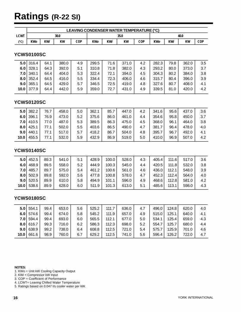
Ratings (R-22 SI)
NOTES:1. KWo = Unit kW Cooling Capacity Output2. KWi = Compressor kW Input3. COP = Coefficient of Performance4. LCWT= Leaving Chilled Water Temperature5. Ratings based on 0.047 l/s cooler water per kW.
LEAVING CONDENSER WATER TEMPERATURE (°C)LCWT 30.0 35.0 40.0
(°C) KWo KWi KW COP KWo KWi KW COP KWo KWi KW COP
YCWS0120SC
YCWS0140SC
YCWS0180SC
YCWS0100SC
5.0 316.4 64.1 380.0 4.9 299.5 71.6 371.0 4.2 282.3 79.8 362.0 3.5 6.0 328.1 64.3 392.0 5.1 310.8 71.8 382.0 4.3 293.2 80.0 373.0 3.7 7.0 340.1 64.4 404.0 5.3 322.4 72.1 394.0 4.5 304.3 80.2 384.0 3.8 8.0 352.4 64.5 416.0 5.5 334.4 72.3 406.0 4.6 315.7 80.4 396.0 3.9 9.0 365.1 64.5 429.0 5.7 346.5 72.5 419.0 4.8 327.6 80.7 408.0 4.110.0 377.9 64.4 442.0 5.9 359.0 72.7 431.0 4.9 339.5 81.0 420.0 4.2
5.0 382.2 76.7 458.0 5.0 362.1 85.7 447.0 4.2 341.6 95.6 437.0 3.6 6.0 396.1 76.9 473.0 5.2 375.6 86.0 461.0 4.4 354.6 95.8 450.0 3.7 7.0 410.5 77.0 487.0 5.3 389.5 86.3 475.0 4.5 368.0 96.1 464.0 3.8 8.0 425.1 77.1 502.0 5.5 403.6 86.5 490.0 4.7 381.7 96.4 478.0 4.0 9.0 440.1 77.1 517.0 5.7 418.2 86.7 504.0 4.8 395.7 96.7 492.0 4.110.0 455.5 77.1 532.0 5.9 432.9 86.9 519.0 5.0 410.0 96.9 507.0 4.2
5.0 452.5 89.3 541.0 5.1 428.9 100.0 528.0 4.3 405.4 111.6 517.0 3.6 6.0 468.9 89.5 558.0 5.2 444.9 100.3 545.0 4.4 420.5 111.8 532.0 3.8 7.0 485.7 89.7 575.0 5.4 461.2 100.6 561.0 4.6 436.0 112.1 548.0 3.9 8.0 502.9 89.8 592.0 5.6 477.8 100.8 578.0 4.7 452.3 112.4 564.0 4.0 9.0 520.5 89.9 610.0 5.8 494.9 101.1 596.0 4.9 468.6 112.8 581.0 4.210.0 538.6 89.9 628.0 6.0 511.9 101.3 613.0 5.1 485.6 113.1 598.0 4.3
5.0 554.1 99.4 653.0 5.6 525.2 111.7 636.0 4.7 496.0 124.8 620.0 4.0 6.0 574.6 99.4 674.0 5.8 545.2 111.9 657.0 4.9 515.0 125.1 640.0 4.1 7.0 594.4 99.4 693.0 6.0 565.5 112.1 677.0 5.0 534.1 125.4 659.0 4.3 8.0 616.7 99.3 716.0 6.2 586.3 112.3 698.0 5.2 554.7 125.7 680.0 4.4 9.0 638.9 99.2 738.0 6.4 608.8 112.5 721.0 5.4 575.7 125.9 701.0 4.610.0 661.6 98.9 760.0 6.7 629.2 112.5 741.0 5.6 596.4 126.2 722.0 4.7
FORM 201.24-EG1
17YORK INTERNATIONAL
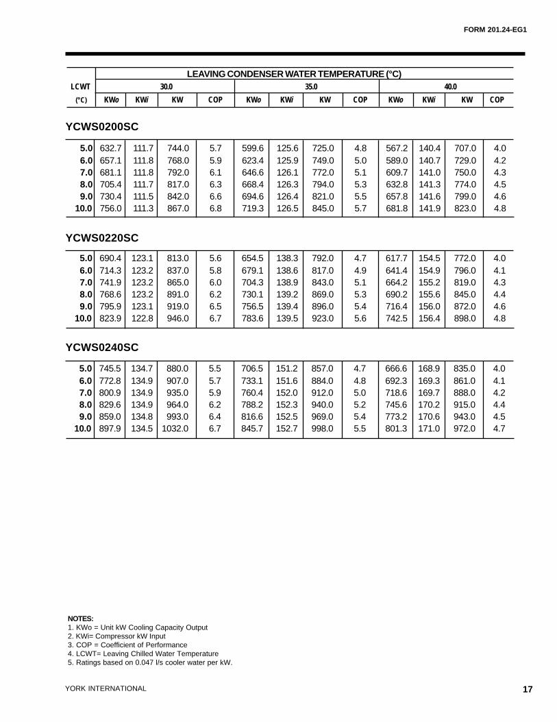
NOTES:1. KWo = Unit kW Cooling Capacity Output2. KWi= Compressor kW Input3. COP = Coefficient of Performance4. LCWT= Leaving Chilled Water Temperature5. Ratings based on 0.047 l/s cooler water per kW.
LEAVING CONDENSER WATER TEMPERATURE (°C)LCWT 30.0 35.0 40.0
(°C) KWo KWi KW COP KWo KWi KW COP KWo KWi KW COP
YCWS0200SC
YCWS0220SC
YCWS0240SC
5.0 632.7 111.7 744.0 5.7 599.6 125.6 725.0 4.8 567.2 140.4 707.0 4.0 6.0 657.1 111.8 768.0 5.9 623.4 125.9 749.0 5.0 589.0 140.7 729.0 4.2 7.0 681.1 111.8 792.0 6.1 646.6 126.1 772.0 5.1 609.7 141.0 750.0 4.3 8.0 705.4 111.7 817.0 6.3 668.4 126.3 794.0 5.3 632.8 141.3 774.0 4.5 9.0 730.4 111.5 842.0 6.6 694.6 126.4 821.0 5.5 657.8 141.6 799.0 4.610.0 756.0 111.3 867.0 6.8 719.3 126.5 845.0 5.7 681.8 141.9 823.0 4.8
5.0 690.4 123.1 813.0 5.6 654.5 138.3 792.0 4.7 617.7 154.5 772.0 4.0 6.0 714.3 123.2 837.0 5.8 679.1 138.6 817.0 4.9 641.4 154.9 796.0 4.1 7.0 741.9 123.2 865.0 6.0 704.3 138.9 843.0 5.1 664.2 155.2 819.0 4.3 8.0 768.6 123.2 891.0 6.2 730.1 139.2 869.0 5.3 690.2 155.6 845.0 4.4 9.0 795.9 123.1 919.0 6.5 756.5 139.4 896.0 5.4 716.4 156.0 872.0 4.610.0 823.9 122.8 946.0 6.7 783.6 139.5 923.0 5.6 742.5 156.4 898.0 4.8
5.0 745.5 134.7 880.0 5.5 706.5 151.2 857.0 4.7 666.6 168.9 835.0 4.0 6.0 772.8 134.9 907.0 5.7 733.1 151.6 884.0 4.8 692.3 169.3 861.0 4.1 7.0 800.9 134.9 935.0 5.9 760.4 152.0 912.0 5.0 718.6 169.7 888.0 4.2 8.0 829.6 134.9 964.0 6.2 788.2 152.3 940.0 5.2 745.6 170.2 915.0 4.4 9.0 859.0 134.8 993.0 6.4 816.6 152.5 969.0 5.4 773.2 170.6 943.0 4.510.0 897.9 134.5 1032.0 6.7 845.7 152.7 998.0 5.5 801.3 171.0 972.0 4.7
18 YORK INTERNATIONAL
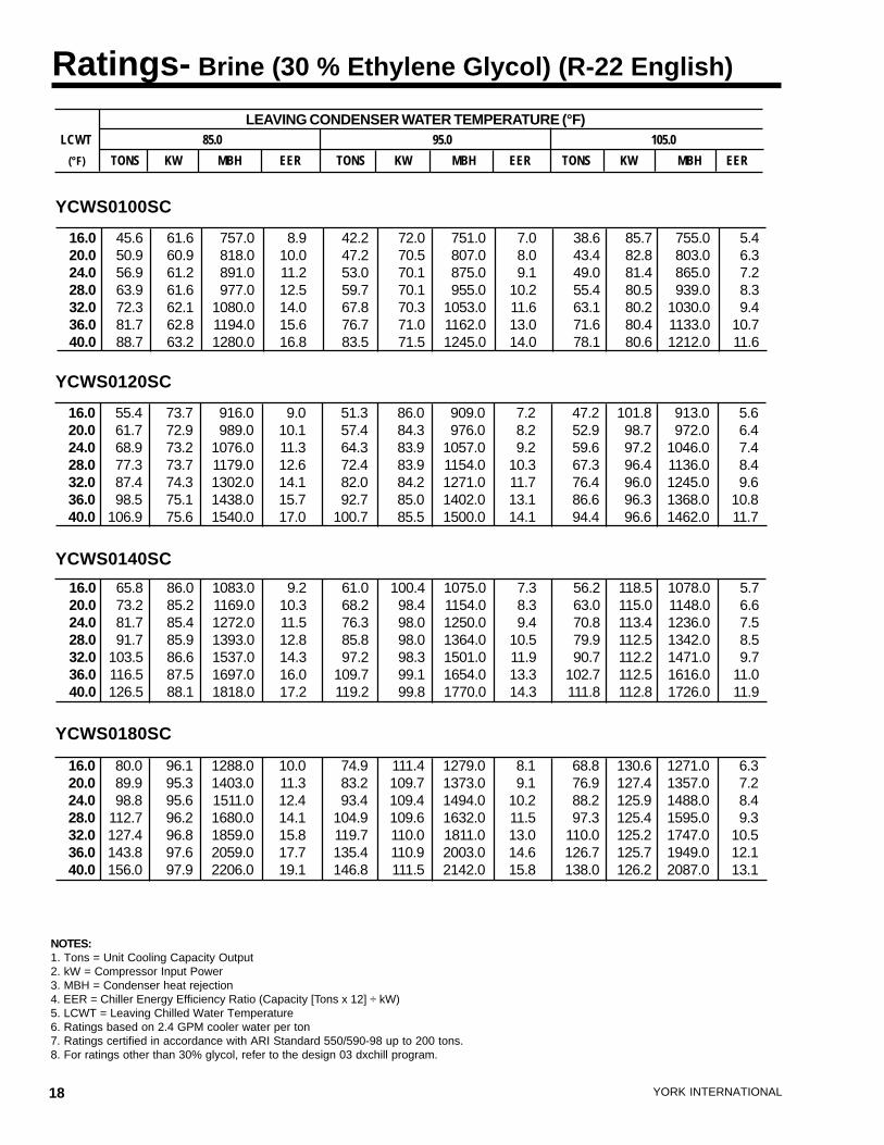
Ratings- Brine (30 % Ethylene Glycol) (R-22 English)
NOTES:1. Tons = Unit Cooling Capacity Output2. kW = Compressor Input Power3. MBH = Condenser heat rejection4. EER = Chiller Energy Efficiency Ratio (Capacity [Tons x 12] ÷ kW)5. LCWT = Leaving Chilled Water Temperature6. Ratings based on 2.4 GPM cooler water per ton7. Ratings certified in accordance with ARI Standard 550/590-98 up to 200 tons.8. For ratings other than 30% glycol, refer to the design 03 dxchill program.
LEAVING CONDENSER WATER TEMPERATURE (°F)LCWT 85.0 95.0 105.0
(°F) TONS KW MBH EER TONS KW MBH EER TONS KW MBH EER
YCWS0120SC
YCWS0140SC
YCWS0180SC
YCWS0100SC
16.0 45.6 61.6 757.0 8.9 42.2 72.0 751.0 7.0 38.6 85.7 755.0 5.420.0 50.9 60.9 818.0 10.0 47.2 70.5 807.0 8.0 43.4 82.8 803.0 6.324.0 56.9 61.2 891.0 11.2 53.0 70.1 875.0 9.1 49.0 81.4 865.0 7.228.0 63.9 61.6 977.0 12.5 59.7 70.1 955.0 10.2 55.4 80.5 939.0 8.332.0 72.3 62.1 1080.0 14.0 67.8 70.3 1053.0 11.6 63.1 80.2 1030.0 9.436.0 81.7 62.8 1194.0 15.6 76.7 71.0 1162.0 13.0 71.6 80.4 1133.0 10.740.0 88.7 63.2 1280.0 16.8 83.5 71.5 1245.0 14.0 78.1 80.6 1212.0 11.6
16.0 55.4 73.7 916.0 9.0 51.3 86.0 909.0 7.2 47.2 101.8 913.0 5.620.0 61.7 72.9 989.0 10.1 57.4 84.3 976.0 8.2 52.9 98.7 972.0 6.424.0 68.9 73.2 1076.0 11.3 64.3 83.9 1057.0 9.2 59.6 97.2 1046.0 7.428.0 77.3 73.7 1179.0 12.6 72.4 83.9 1154.0 10.3 67.3 96.4 1136.0 8.432.0 87.4 74.3 1302.0 14.1 82.0 84.2 1271.0 11.7 76.4 96.0 1245.0 9.636.0 98.5 75.1 1438.0 15.7 92.7 85.0 1402.0 13.1 86.6 96.3 1368.0 10.840.0 106.9 75.6 1540.0 17.0 100.7 85.5 1500.0 14.1 94.4 96.6 1462.0 11.7
16.0 65.8 86.0 1083.0 9.2 61.0 100.4 1075.0 7.3 56.2 118.5 1078.0 5.720.0 73.2 85.2 1169.0 10.3 68.2 98.4 1154.0 8.3 63.0 115.0 1148.0 6.624.0 81.7 85.4 1272.0 11.5 76.3 98.0 1250.0 9.4 70.8 113.4 1236.0 7.528.0 91.7 85.9 1393.0 12.8 85.8 98.0 1364.0 10.5 79.9 112.5 1342.0 8.532.0 103.5 86.6 1537.0 14.3 97.2 98.3 1501.0 11.9 90.7 112.2 1471.0 9.736.0 116.5 87.5 1697.0 16.0 109.7 99.1 1654.0 13.3 102.7 112.5 1616.0 11.040.0 126.5 88.1 1818.0 17.2 119.2 99.8 1770.0 14.3 111.8 112.8 1726.0 11.9
16.0 80.0 96.1 1288.0 10.0 74.9 111.4 1279.0 8.1 68.8 130.6 1271.0 6.320.0 89.9 95.3 1403.0 11.3 83.2 109.7 1373.0 9.1 76.9 127.4 1357.0 7.224.0 98.8 95.6 1511.0 12.4 93.4 109.4 1494.0 10.2 88.2 125.9 1488.0 8.428.0 112.7 96.2 1680.0 14.1 104.9 109.6 1632.0 11.5 97.3 125.4 1595.0 9.332.0 127.4 96.8 1859.0 15.8 119.7 110.0 1811.0 13.0 110.0 125.2 1747.0 10.536.0 143.8 97.6 2059.0 17.7 135.4 110.9 2003.0 14.6 126.7 125.7 1949.0 12.140.0 156.0 97.9 2206.0 19.1 146.8 111.5 2142.0 15.8 138.0 126.2 2087.0 13.1
FORM 201.24-EG1
19YORK INTERNATIONAL
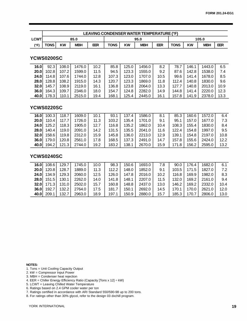
NOTES:1. Tons = Unit Cooling Capacity Output2. kW = Compressor Input Power3. MBH = Condenser heat rejection4. EER = Chiller Energy Efficiency Ratio (Capacity [Tons x 12] ÷ kW)5. LCWT = Leaving Chilled Water Temperature6. Ratings based on 2.4 GPM cooler water per ton7. Ratings certified in accordance with ARI Standard 550/590-98 up to 200 tons.8. For ratings other than 30% glycol, refer to the design 03 dxchill program.
LEAVING CONDENSER WATER TEMPERATURE (°F)LCWT 85.0 95.0 105.0
(°F) TONS KW MBH EER TONS KW MBH EER TONS KW MBH EER
YCWS0200SC
YCWS0220SC
YCWS0240SC
16.0 92.3 108.0 1476.0 10.2 85.8 125.0 1456.0 8.2 78.7 146.1 1443.0 6.520.0 102.8 107.2 1599.0 11.5 94.5 123.3 1555.0 9.2 87.6 142.8 1538.0 7.424.0 114.8 107.6 1744.0 12.8 107.3 123.0 1707.0 10.5 99.6 141.4 1678.0 8.528.0 128.8 108.2 1915.0 14.3 120.7 123.3 1869.0 11.8 112.4 140.8 1830.0 9.632.0 145.7 108.9 2119.0 16.1 136.8 123.8 2064.0 13.3 127.7 140.8 2013.0 10.936.0 164.3 109.7 2346.0 18.0 154.7 124.8 2282.0 14.9 144.8 141.4 2220.0 12.340.0 178.3 110.1 2515.0 19.4 168.1 125.4 2445.0 16.1 157.8 141.9 2378.0 13.3
16.0 100.3 118.7 1609.0 10.1 93.1 137.4 1586.0 8.1 85.3 160.6 1572.0 6.420.0 110.4 117.7 1726.0 11.3 103.2 135.4 1701.0 9.1 95.1 157.0 1677.0 7.324.0 125.2 118.3 1905.0 12.7 116.8 135.2 1862.0 10.4 108.3 155.4 1830.0 8.428.0 140.4 119.0 2091.0 14.2 131.5 135.5 2041.0 11.6 122.4 154.8 1997.0 9.532.0 158.6 119.8 2312.0 15.9 145.8 136.0 2213.0 12.9 139.1 154.8 2197.0 10.836.0 179.0 120.8 2561.0 17.8 168.5 137.3 2491.0 14.7 157.8 155.6 2424.0 12.240.0 194.2 121.3 2744.0 19.2 183.2 138.1 2670.0 15.9 171.8 156.2 2595.0 13.2
16.0 108.6 129.7 1745.0 10.0 98.3 150.6 1693.0 7.8 90.0 176.4 1682.0 6.120.0 120.8 128.7 1889.0 11.3 112.2 148.0 1852.0 9.1 103.5 171.5 1827.0 7.224.0 134.9 129.3 2060.0 12.5 126.0 147.8 2016.0 10.2 116.8 169.9 1982.0 8.328.0 151.5 130.1 2262.0 14.0 141.8 148.1 2207.0 11.5 132.0 169.2 2161.0 9.432.0 171.3 131.0 2502.0 15.7 160.8 148.8 2437.0 13.0 146.2 169.2 2332.0 10.436.0 192.7 132.2 2764.0 17.5 181.7 150.1 2692.0 14.5 170.1 170.0 2621.0 12.040.0 209.1 132.7 2963.0 18.9 197.1 150.9 2880.0 15.7 185.3 170.7 2806.0 13.0
20 YORK INTERNATIONAL
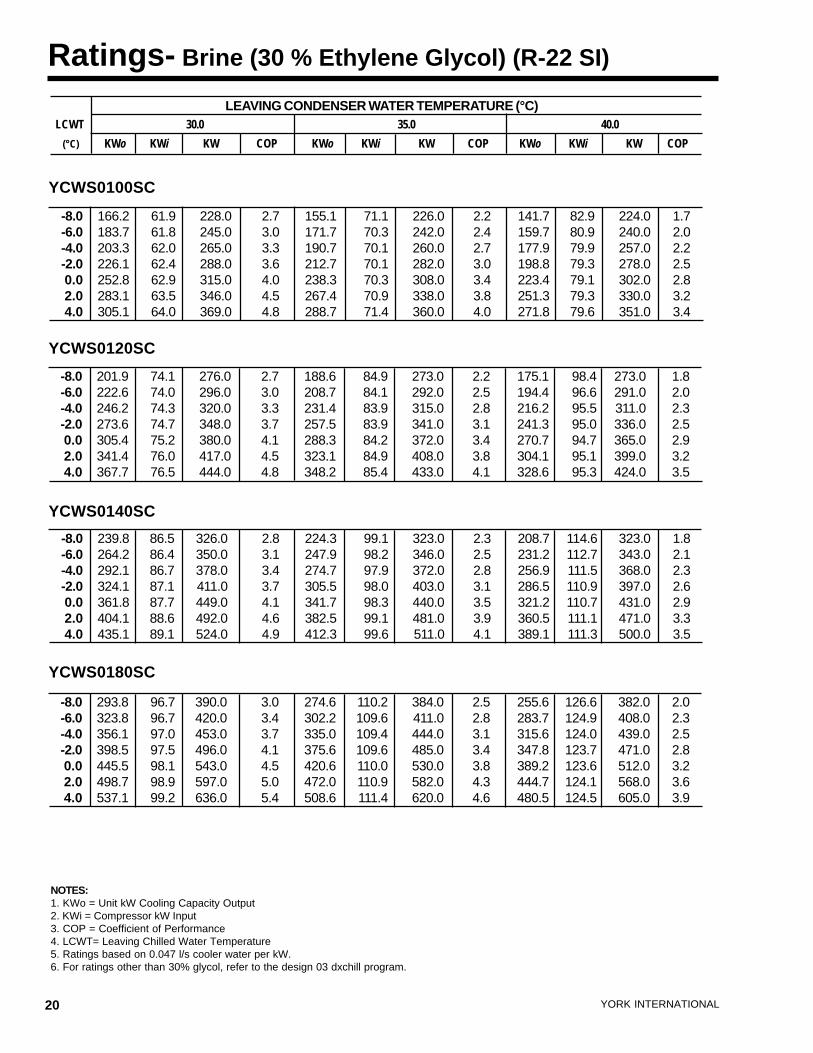
Ratings- Brine (30 % Ethylene Glycol) (R-22 SI)
NOTES:1. KWo = Unit kW Cooling Capacity Output2. KWi = Compressor kW Input3. COP = Coefficient of Performance4. LCWT= Leaving Chilled Water Temperature5. Ratings based on 0.047 l/s cooler water per kW.6. For ratings other than 30% glycol, refer to the design 03 dxchill program.
LEAVING CONDENSER WATER TEMPERATURE (°C)LCWT 30.0 35.0 40.0
(°C) KWo KWi KW COP KWo KWi KW COP KWo KWi KW COP
YCWS0120SC
YCWS0140SC
YCWS0180SC
YCWS0100SC
-8.0 166.2 61.9 228.0 2.7 155.1 71.1 226.0 2.2 141.7 82.9 224.0 1.7-6.0 183.7 61.8 245.0 3.0 171.7 70.3 242.0 2.4 159.7 80.9 240.0 2.0-4.0 203.3 62.0 265.0 3.3 190.7 70.1 260.0 2.7 177.9 79.9 257.0 2.2-2.0 226.1 62.4 288.0 3.6 212.7 70.1 282.0 3.0 198.8 79.3 278.0 2.5 0.0 252.8 62.9 315.0 4.0 238.3 70.3 308.0 3.4 223.4 79.1 302.0 2.8 2.0 283.1 63.5 346.0 4.5 267.4 70.9 338.0 3.8 251.3 79.3 330.0 3.2 4.0 305.1 64.0 369.0 4.8 288.7 71.4 360.0 4.0 271.8 79.6 351.0 3.4
-8.0 201.9 74.1 276.0 2.7 188.6 84.9 273.0 2.2 175.1 98.4 273.0 1.8-6.0 222.6 74.0 296.0 3.0 208.7 84.1 292.0 2.5 194.4 96.6 291.0 2.0-4.0 246.2 74.3 320.0 3.3 231.4 83.9 315.0 2.8 216.2 95.5 311.0 2.3-2.0 273.6 74.7 348.0 3.7 257.5 83.9 341.0 3.1 241.3 95.0 336.0 2.5 0.0 305.4 75.2 380.0 4.1 288.3 84.2 372.0 3.4 270.7 94.7 365.0 2.9 2.0 341.4 76.0 417.0 4.5 323.1 84.9 408.0 3.8 304.1 95.1 399.0 3.2 4.0 367.7 76.5 444.0 4.8 348.2 85.4 433.0 4.1 328.6 95.3 424.0 3.5
-8.0 239.8 86.5 326.0 2.8 224.3 99.1 323.0 2.3 208.7 114.6 323.0 1.8-6.0 264.2 86.4 350.0 3.1 247.9 98.2 346.0 2.5 231.2 112.7 343.0 2.1-4.0 292.1 86.7 378.0 3.4 274.7 97.9 372.0 2.8 256.9 111.5 368.0 2.3-2.0 324.1 87.1 411.0 3.7 305.5 98.0 403.0 3.1 286.5 110.9 397.0 2.6 0.0 361.8 87.7 449.0 4.1 341.7 98.3 440.0 3.5 321.2 110.7 431.0 2.9 2.0 404.1 88.6 492.0 4.6 382.5 99.1 481.0 3.9 360.5 111.1 471.0 3.3 4.0 435.1 89.1 524.0 4.9 412.3 99.6 511.0 4.1 389.1 111.3 500.0 3.5
-8.0 293.8 96.7 390.0 3.0 274.6 110.2 384.0 2.5 255.6 126.6 382.0 2.0-6.0 323.8 96.7 420.0 3.4 302.2 109.6 411.0 2.8 283.7 124.9 408.0 2.3-4.0 356.1 97.0 453.0 3.7 335.0 109.4 444.0 3.1 315.6 124.0 439.0 2.5-2.0 398.5 97.5 496.0 4.1 375.6 109.6 485.0 3.4 347.8 123.7 471.0 2.8 0.0 445.5 98.1 543.0 4.5 420.6 110.0 530.0 3.8 389.2 123.6 512.0 3.2 2.0 498.7 98.9 597.0 5.0 472.0 110.9 582.0 4.3 444.7 124.1 568.0 3.6 4.0 537.1 99.2 636.0 5.4 508.6 111.4 620.0 4.6 480.5 124.5 605.0 3.9
FORM 201.24-EG1
21YORK INTERNATIONAL
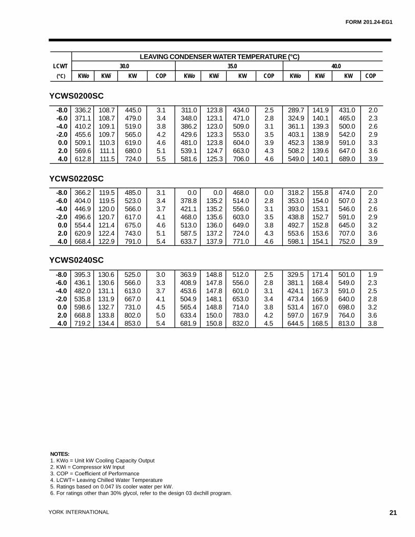
NOTES:1. KWo = Unit kW Cooling Capacity Output2. KWi = Compressor kW Input3. COP = Coefficient of Performance4. LCWT= Leaving Chilled Water Temperature5. Ratings based on 0.047 l/s cooler water per kW.6. For ratings other than 30% glycol, refer to the design 03 dxchill program.
LEAVING CONDENSER WATER TEMPERATURE (°C)LCWT 30.0 35.0 40.0
(°C) KWo KWi KW COP KWo KWi KW COP KWo KWi KW COP
YCWS0200SC
YCWS0220SC
YCWS0240SC
-8.0 336.2 108.7 445.0 3.1 311.0 123.8 434.0 2.5 289.7 141.9 431.0 2.0-6.0 371.1 108.7 479.0 3.4 348.0 123.1 471.0 2.8 324.9 140.1 465.0 2.3-4.0 410.2 109.1 519.0 3.8 386.2 123.0 509.0 3.1 361.1 139.3 500.0 2.6-2.0 455.6 109.7 565.0 4.2 429.6 123.3 553.0 3.5 403.1 138.9 542.0 2.9 0.0 509.1 110.3 619.0 4.6 481.0 123.8 604.0 3.9 452.3 138.9 591.0 3.3 2.0 569.6 111.1 680.0 5.1 539.1 124.7 663.0 4.3 508.2 139.6 647.0 3.6 4.0 612.8 111.5 724.0 5.5 581.6 125.3 706.0 4.6 549.0 140.1 689.0 3.9
-8.0 366.2 119.5 485.0 3.1 0.0 0.0 468.0 0.0 318.2 155.8 474.0 2.0-6.0 404.0 119.5 523.0 3.4 378.8 135.2 514.0 2.8 353.0 154.0 507.0 2.3-4.0 446.9 120.0 566.0 3.7 421.1 135.2 556.0 3.1 393.0 153.1 546.0 2.6-2.0 496.6 120.7 617.0 4.1 468.0 135.6 603.0 3.5 438.8 152.7 591.0 2.9 0.0 554.4 121.4 675.0 4.6 513.0 136.0 649.0 3.8 492.7 152.8 645.0 3.2 2.0 620.9 122.4 743.0 5.1 587.5 137.2 724.0 4.3 553.6 153.6 707.0 3.6 4.0 668.4 122.9 791.0 5.4 633.7 137.9 771.0 4.6 598.1 154.1 752.0 3.9
-8.0 395.3 130.6 525.0 3.0 363.9 148.8 512.0 2.5 329.5 171.4 501.0 1.9-6.0 436.1 130.6 566.0 3.3 408.9 147.8 556.0 2.8 381.1 168.4 549.0 2.3-4.0 482.0 131.1 613.0 3.7 453.6 147.8 601.0 3.1 424.1 167.3 591.0 2.5-2.0 535.8 131.9 667.0 4.1 504.9 148.1 653.0 3.4 473.4 166.9 640.0 2.8 0.0 598.6 132.7 731.0 4.5 565.4 148.8 714.0 3.8 531.4 167.0 698.0 3.2 2.0 668.8 133.8 802.0 5.0 633.4 150.0 783.0 4.2 597.0 167.9 764.0 3.6 4.0 719.2 134.4 853.0 5.4 681.9 150.8 832.0 4.5 644.5 168.5 813.0 3.8
22 YORK INTERNATIONAL
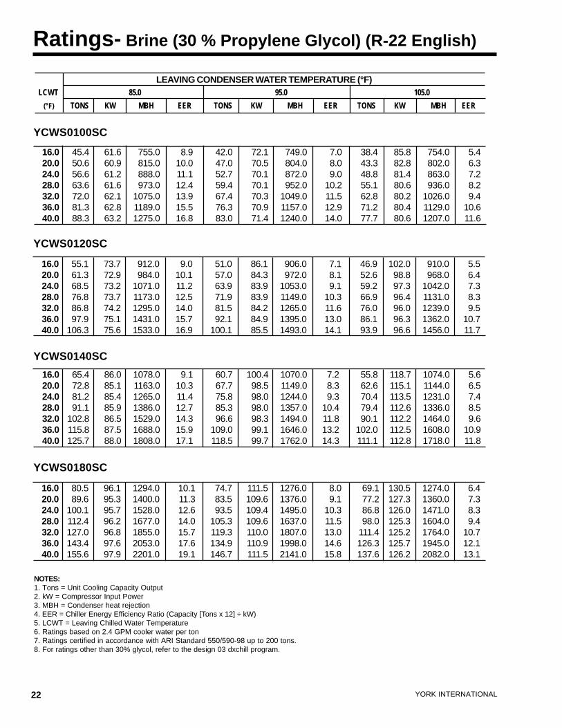
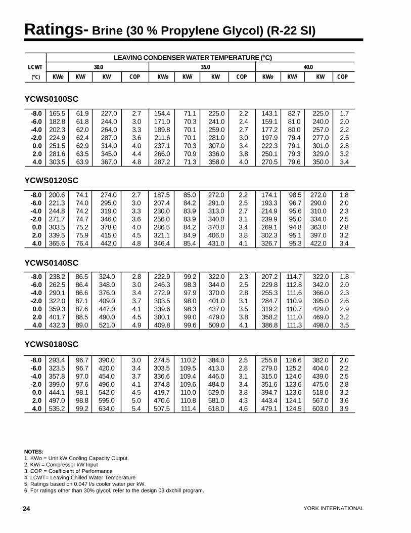
Ratings- Brine (30 % Propylene Glycol) (R-22 English)
NOTES:1. Tons = Unit Cooling Capacity Output2. kW = Compressor Input Power3. MBH = Condenser heat rejection4. EER = Chiller Energy Efficiency Ratio (Capacity [Tons x 12] ÷ kW)5. LCWT = Leaving Chilled Water Temperature6. Ratings based on 2.4 GPM cooler water per ton7. Ratings certified in accordance with ARI Standard 550/590-98 up to 200 tons.8. For ratings other than 30% glycol, refer to the design 03 dxchill program.
YCWS0120SC
YCWS0140SC
YCWS0180SC
YCWS0100SC
LEAVING CONDENSER WATER TEMPERATURE (°F)LCWT 85.0 95.0 105.0
(°F) TONS KW MBH EER TONS KW MBH EER TONS KW MBH EER
16.0 45.4 61.6 755.0 8.9 42.0 72.1 749.0 7.0 38.4 85.8 754.0 5.420.0 50.6 60.9 815.0 10.0 47.0 70.5 804.0 8.0 43.3 82.8 802.0 6.324.0 56.6 61.2 888.0 11.1 52.7 70.1 872.0 9.0 48.8 81.4 863.0 7.228.0 63.6 61.6 973.0 12.4 59.4 70.1 952.0 10.2 55.1 80.6 936.0 8.232.0 72.0 62.1 1075.0 13.9 67.4 70.3 1049.0 11.5 62.8 80.2 1026.0 9.436.0 81.3 62.8 1189.0 15.5 76.3 70.9 1157.0 12.9 71.2 80.4 1129.0 10.640.0 88.3 63.2 1275.0 16.8 83.0 71.4 1240.0 14.0 77.7 80.6 1207.0 11.6
16.0 55.1 73.7 912.0 9.0 51.0 86.1 906.0 7.1 46.9 102.0 910.0 5.520.0 61.3 72.9 984.0 10.1 57.0 84.3 972.0 8.1 52.6 98.8 968.0 6.424.0 68.5 73.2 1071.0 11.2 63.9 83.9 1053.0 9.1 59.2 97.3 1042.0 7.328.0 76.8 73.7 1173.0 12.5 71.9 83.9 1149.0 10.3 66.9 96.4 1131.0 8.332.0 86.8 74.2 1295.0 14.0 81.5 84.2 1265.0 11.6 76.0 96.0 1239.0 9.536.0 97.9 75.1 1431.0 15.7 92.1 84.9 1395.0 13.0 86.1 96.3 1362.0 10.740.0 106.3 75.6 1533.0 16.9 100.1 85.5 1493.0 14.1 93.9 96.6 1456.0 11.7
16.0 65.4 86.0 1078.0 9.1 60.7 100.4 1070.0 7.2 55.8 118.7 1074.0 5.620.0 72.8 85.1 1163.0 10.3 67.7 98.5 1149.0 8.3 62.6 115.1 1144.0 6.524.0 81.2 85.4 1265.0 11.4 75.8 98.0 1244.0 9.3 70.4 113.5 1231.0 7.428.0 91.1 85.9 1386.0 12.7 85.3 98.0 1357.0 10.4 79.4 112.6 1336.0 8.532.0 102.8 86.5 1529.0 14.3 96.6 98.3 1494.0 11.8 90.1 112.2 1464.0 9.636.0 115.8 87.5 1688.0 15.9 109.0 99.1 1646.0 13.2 102.0 112.5 1608.0 10.940.0 125.7 88.0 1808.0 17.1 118.5 99.7 1762.0 14.3 111.1 112.8 1718.0 11.8
16.0 80.5 96.1 1294.0 10.1 74.7 111.5 1276.0 8.0 69.1 130.5 1274.0 6.420.0 89.6 95.3 1400.0 11.3 83.5 109.6 1376.0 9.1 77.2 127.3 1360.0 7.324.0 100.1 95.7 1528.0 12.6 93.5 109.4 1495.0 10.3 86.8 126.0 1471.0 8.328.0 112.4 96.2 1677.0 14.0 105.3 109.6 1637.0 11.5 98.0 125.3 1604.0 9.432.0 127.0 96.8 1855.0 15.7 119.3 110.0 1807.0 13.0 111.4 125.2 1764.0 10.736.0 143.4 97.6 2053.0 17.6 134.9 110.9 1998.0 14.6 126.3 125.7 1945.0 12.140.0 155.6 97.9 2201.0 19.1 146.7 111.5 2141.0 15.8 137.6 126.2 2082.0 13.1
FORM 201.24-EG1
23YORK INTERNATIONAL
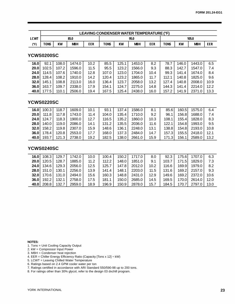
NOTES:1. Tons = Unit Cooling Capacity Output2. kW = Compressor Input Power3. MBH = Condenser heat rejection4. EER = Chiller Energy Efficiency Ratio (Capacity [Tons x 12] ÷ kW)5. LCWT = Leaving Chilled Water Temperature6. Ratings based on 2.4 GPM cooler water per ton7. Ratings certified in accordance with ARI Standard 550/590-98 up to 200 tons.8. For ratings other than 30% glycol, refer to the design 03 dxchill program.
YCWS0200SC
YCWS0220SC
YCWS0240SC
16.0 92.1 108.0 1474.0 10.2 85.5 125.1 1453.0 8.2 78.7 146.0 1443.0 6.520.0 102.5 107.2 1596.0 11.5 95.5 123.2 1566.0 9.3 88.3 142.7 1547.0 7.424.0 114.5 107.6 1740.0 12.8 107.0 123.0 1704.0 10.4 99.3 141.4 1674.0 8.428.0 128.4 108.2 1910.0 14.2 120.4 123.2 1865.0 11.7 112.1 140.8 1825.0 9.632.0 145.1 108.8 2113.0 16.0 136.4 123.7 2058.0 13.2 127.4 140.8 2008.0 10.936.0 163.7 109.7 2338.0 17.9 154.1 124.7 2275.0 14.8 144.3 141.4 2214.0 12.240.0 177.5 110.1 2506.0 19.4 167.5 125.4 2438.0 16.0 157.2 141.9 2371.0 13.3
16.0 100.3 118.7 1609.0 10.1 93.1 137.4 1586.0 8.1 85.6 160.5 1575.0 6.420.0 111.8 117.8 1743.0 11.4 104.0 135.4 1710.0 9.2 96.1 156.8 1688.0 7.424.0 124.7 118.3 1900.0 12.7 116.5 135.2 1860.0 10.3 108.1 155.4 1828.0 8.328.0 140.0 119.0 2086.0 14.1 131.2 135.5 2036.0 11.6 122.1 154.8 1993.0 9.532.0 158.2 119.8 2307.0 15.9 148.6 136.1 2248.0 13.1 138.8 154.8 2193.0 10.836.0 178.4 120.8 2553.0 17.7 168.0 137.3 2484.0 14.7 157.3 155.5 2418.0 12.140.0 193.7 121.3 2738.0 19.2 182.5 138.0 2661.0 15.9 171.3 156.1 2589.0 13.2
16.0 108.3 129.7 1742.0 10.0 100.4 150.2 1717.0 8.0 92.3 175.6 1707.0 6.320.0 120.5 128.7 1885.0 11.2 112.2 148.0 1851.0 9.1 103.7 171.5 1829.0 7.324.0 134.6 129.3 2056.0 12.5 125.7 147.8 2012.0 10.2 116.6 169.9 1979.0 8.228.0 151.0 130.1 2256.0 13.9 141.4 148.1 2203.0 11.5 131.6 169.2 2157.0 9.332.0 170.6 131.0 2494.0 15.6 160.3 148.8 2431.0 12.9 149.6 169.2 2372.0 10.636.0 192.2 132.1 2758.0 17.5 181.1 150.0 2685.0 14.5 169.5 170.0 2614.0 12.040.0 208.8 132.7 2959.0 18.9 196.9 150.9 2878.0 15.7 184.5 170.7 2797.0 13.0
LEAVING CONDENSER WATER TEMPERATURE (°F)LCWT 85.0 95.0 105.0
(°F) TONS KW MBH EER TONS KW MBH EER TONS KW MBH EER
24 YORK INTERNATIONAL
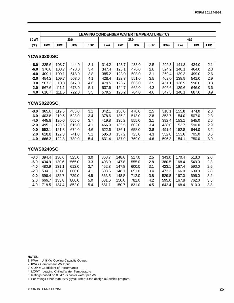
Ratings- Brine (30 % Propylene Glycol) (R-22 SI)
NOTES:1. KWo = Unit kW Cooling Capacity Output2. KWi = Compressor kW Input3. COP = Coefficient of Performance4. LCWT= Leaving Chilled Water Temperature5. Ratings based on 0.047 l/s cooler water per kW.6. For ratings other than 30% glycol, refer to the design 03 dxchill program.
LEAVING CONDENSER WATER TEMPERATURE (°C)LCWT 30.0 35.0 40.0
(°C) KWo KWi KW COP KWo KWi KW COP KWo KWi KW COP
YCWS0120SC
YCWS0140SC
YCWS0180SC
YCWS0100SC
-8.0 165.5 61.9 227.0 2.7 154.4 71.1 225.0 2.2 143.1 82.7 225.0 1.7-6.0 182.8 61.8 244.0 3.0 171.0 70.3 241.0 2.4 159.1 81.0 240.0 2.0-4.0 202.3 62.0 264.0 3.3 189.8 70.1 259.0 2.7 177.2 80.0 257.0 2.2-2.0 224.9 62.4 287.0 3.6 211.6 70.1 281.0 3.0 197.9 79.4 277.0 2.5 0.0 251.5 62.9 314.0 4.0 237.1 70.3 307.0 3.4 222.3 79.1 301.0 2.8 2.0 281.6 63.5 345.0 4.4 266.0 70.9 336.0 3.8 250.1 79.3 329.0 3.2 4.0 303.5 63.9 367.0 4.8 287.2 71.3 358.0 4.0 270.5 79.6 350.0 3.4
-8.0 200.6 74.1 274.0 2.7 187.5 85.0 272.0 2.2 174.1 98.5 272.0 1.8-6.0 221.3 74.0 295.0 3.0 207.4 84.2 291.0 2.5 193.3 96.7 290.0 2.0-4.0 244.8 74.2 319.0 3.3 230.0 83.9 313.0 2.7 214.9 95.6 310.0 2.3-2.0 271.7 74.7 346.0 3.6 256.0 83.9 340.0 3.1 239.9 95.0 334.0 2.5 0.0 303.5 75.2 378.0 4.0 286.5 84.2 370.0 3.4 269.1 94.8 363.0 2.8 2.0 339.5 75.9 415.0 4.5 321.1 84.9 406.0 3.8 302.3 95.1 397.0 3.2 4.0 365.6 76.4 442.0 4.8 346.4 85.4 431.0 4.1 326.7 95.3 422.0 3.4
-8.0 238.2 86.5 324.0 2.8 222.9 99.2 322.0 2.3 207.2 114.7 322.0 1.8-6.0 262.5 86.4 348.0 3.0 246.3 98.3 344.0 2.5 229.8 112.8 342.0 2.0-4.0 290.1 86.6 376.0 3.4 272.9 97.9 370.0 2.8 255.3 111.6 366.0 2.3-2.0 322.0 87.1 409.0 3.7 303.5 98.0 401.0 3.1 284.7 110.9 395.0 2.6 0.0 359.3 87.6 447.0 4.1 339.6 98.3 437.0 3.5 319.2 110.7 429.0 2.9 2.0 401.7 88.5 490.0 4.5 380.1 99.0 479.0 3.8 358.2 111.0 469.0 3.2 4.0 432.3 89.0 521.0 4.9 409.8 99.6 509.0 4.1 386.8 111.3 498.0 3.5
-8.0 293.4 96.7 390.0 3.0 274.5 110.2 384.0 2.5 255.8 126.6 382.0 2.0-6.0 323.5 96.7 420.0 3.4 303.5 109.5 413.0 2.8 279.0 125.2 404.0 2.2-4.0 357.8 97.0 454.0 3.7 336.6 109.4 446.0 3.1 315.0 124.0 439.0 2.5-2.0 399.0 97.6 496.0 4.1 374.8 109.6 484.0 3.4 351.6 123.6 475.0 2.8 0.0 444.1 98.1 542.0 4.5 419.7 110.0 529.0 3.8 394.7 123.6 518.0 3.2 2.0 497.0 98.8 595.0 5.0 470.6 110.8 581.0 4.3 443.4 124.1 567.0 3.6 4.0 535.2 99.2 634.0 5.4 507.5 111.4 618.0 4.6 479.1 124.5 603.0 3.9
FORM 201.24-EG1
25YORK INTERNATIONAL
NOTES:1. KWo = Unit kW Cooling Capacity Output2. KWi = Compressor kW Input3. COP = Coefficient of Performance4. LCWT= Leaving Chilled Water Temperature5. Ratings based on 0.047 l/s cooler water per kW.6. For ratings other than 30% glycol, refer to the design 03 dxchill program.
LEAVING CONDENSER WATER TEMPERATURE (°C)LCWT 30.0 35.0 40.0
(°C) KWo KWi KW COP KWo KWi KW COP KWo KWi KW COP
YCWS0200SC
YCWS0220SC
YCWS0240SC
-8.0 335.6 108.7 444.0 3.1 314.2 123.7 438.0 2.5 292.3 141.8 434.0 2.1-6.0 370.0 108.7 478.0 3.4 347.4 123.1 470.0 2.8 324.2 140.1 464.0 2.3-4.0 409.1 109.1 518.0 3.8 385.2 123.0 508.0 3.1 360.4 139.3 499.0 2.6-2.0 454.2 109.7 563.0 4.1 428.4 123.3 551.0 3.5 402.0 138.9 541.0 2.9 0.0 507.3 110.3 617.0 4.6 479.5 123.7 603.0 3.9 451.1 138.9 590.0 3.3 2.0 567.6 111.1 678.0 5.1 537.5 124.7 662.0 4.3 506.6 139.6 646.0 3.6 4.0 610.7 111.5 722.0 5.5 579.5 125.2 704.0 4.6 547.3 140.1 687.0 3.9
-8.0 365.6 119.5 485.0 3.1 342.1 136.0 478.0 2.5 318.1 155.8 474.0 2.0-6.0 403.8 119.5 523.0 3.4 378.6 135.2 513.0 2.8 353.7 154.0 507.0 2.3-4.0 445.8 120.0 565.0 3.7 419.8 135.2 555.0 3.1 392.4 153.1 545.0 2.6-2.0 495.1 120.6 615.0 4.1 466.9 135.5 602.0 3.4 438.0 152.7 590.0 2.9 0.0 553.1 121.3 674.0 4.6 522.6 136.1 658.0 3.8 491.4 152.8 644.0 3.2 2.0 618.8 122.3 741.0 5.1 585.8 137.2 723.0 4.3 552.0 153.6 705.0 3.6 4.0 666.3 122.8 789.0 5.4 631.4 137.9 769.0 4.6 596.3 154.1 750.0 3.9
-8.0 394.4 130.6 525.0 3.0 368.7 148.6 517.0 2.5 343.0 170.4 513.0 2.0-6.0 434.9 130.6 565.0 3.3 408.0 147.8 555.0 2.8 380.5 168.4 549.0 2.3-4.0 480.9 131.1 612.0 3.7 452.3 147.8 600.0 3.1 423.1 167.4 590.0 2.5-2.0 534.1 131.8 666.0 4.1 503.5 148.1 651.0 3.4 472.2 166.9 639.0 2.8 0.0 596.4 132.7 729.0 4.5 563.5 148.8 712.0 3.8 529.8 167.0 696.0 3.2 2.0 666.7 133.8 800.0 5.0 631.6 150.0 781.0 4.2 595.0 167.8 762.0 3.5 4.0 718.5 134.4 852.0 5.4 681.1 150.7 831.0 4.5 642.4 168.4 810.0 3.8
26 YORK INTERNATIONAL
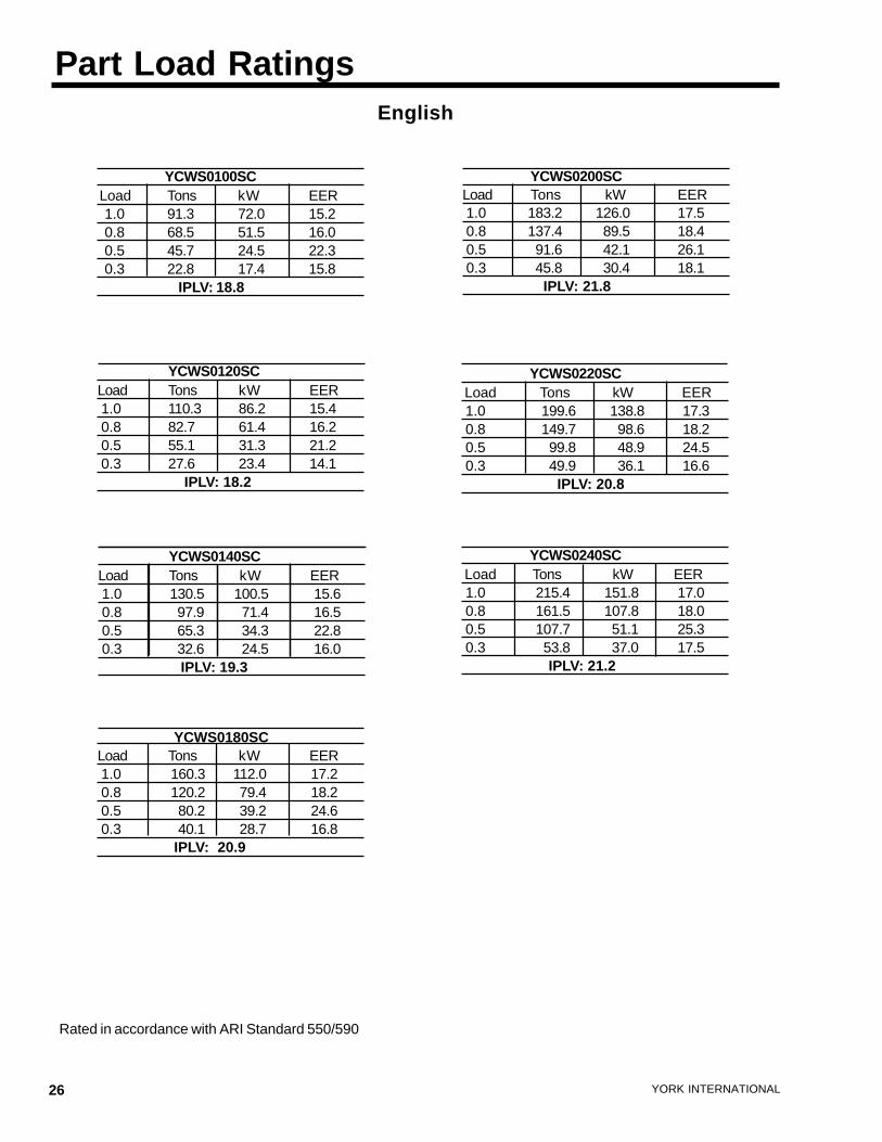
Part Load Ratings
Rated in accordance with ARI Standard 550/590
English
YCWS0100SC Load Tons kW EER 1.0 91.3 72.0 15.2 0.8 68.5 51.5 16.0 0.5 45.7 24.5 22.3 0.3 22.8 17.4 15.8
IPLV: 18.8
YCWS0200SCLoad Tons kW EER 1.0 183.2 126.0 17.5 0.8 137.4 89.5 18.4 0.5 91.6 42.1 26.1 0.3 45.8 30.4 18.1 IPLV: 21.8
YCWS0120SCLoad Tons kW EER 1.0 110.3 86.2 15.4 0.8 82.7 61.4 16.2 0.5 55.1 31.3 21.2 0.3 27.6 23.4 14.1
IPLV: 18.2
YCWS0220SC Load Tons kW EER 1.0 199.6 138.8 17.3 0.8 149.7 98.6 18.2 0.5 99.8 48.9 24.5 0.3 49.9 36.1 16.6
IPLV: 20.8
YCWS0240SC Load Tons kW EER 1.0 215.4 151.8 17.0 0.8 161.5 107.8 18.0 0.5 107.7 51.1 25.3 0.3 53.8 37.0 17.5
IPLV: 21.2
YCWS0140SCLoad Tons kW EER 1.0 130.5 100.5 15.6 0.8 97.9 71.4 16.5 0.5 65.3 34.3 22.8 0.3 32.6 24.5 16.0
IPLV: 19.3
YCWS0180SCLoad Tons kW EER 1.0 160.3 112.0 17.2 0.8 120.2 79.4 18.2 0.5 80.2 39.2 24.6 0.3 40.1 28.7 16.8 IPLV: 20.9
FORM 201.24-EG1
27YORK INTERNATIONAL
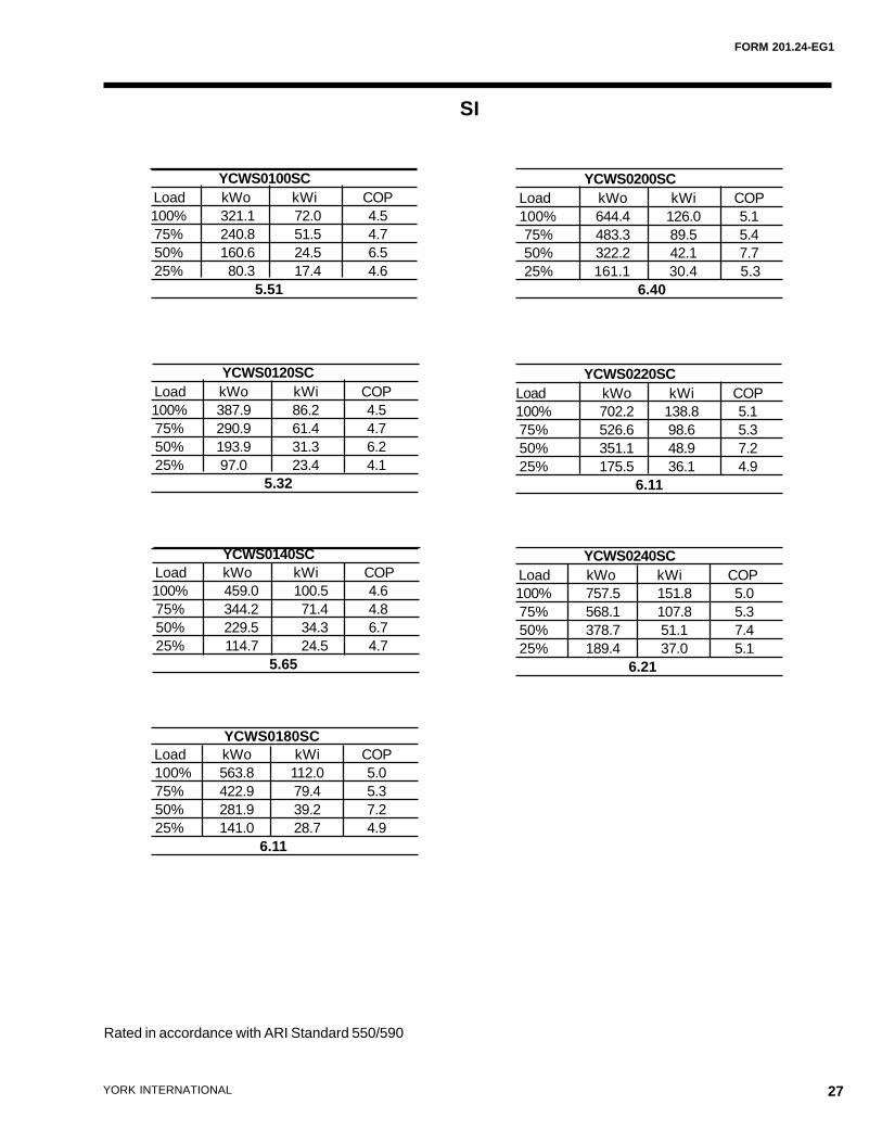
Rated in accordance with ARI Standard 550/590
SI
YCWS0100SC Load kWo kWi COP100% 321.1 72.0 4.5 75% 240.8 51.5 4.7 50% 160.6 24.5 6.5 25% 80.3 17.4 4.6
5.51
YCWS0120SC Load kWo kWi COP100% 387.9 86.2 4.5 75% 290.9 61.4 4.7 50% 193.9 31.3 6.2 25% 97.0 23.4 4.1
5.32
YCWS0220SCLoad kWo kWi COP100% 702.2 138.8 5.1 75% 526.6 98.6 5.3 50% 351.1 48.9 7.2 25% 175.5 36.1 4.9 6.11
YCWS0240SC Load kWo kWi COP100% 757.5 151.8 5.0 75% 568.1 107.8 5.3 50% 378.7 51.1 7.4 25% 189.4 37.0 5.1
6.21
YCWS0180SC Load kWo kWi COP 100% 563.8 112.0 5.0 75% 422.9 79.4 5.3 50% 281.9 39.2 7.2 25% 141.0 28.7 4.9
6.11
YCWS0140SC Load kWo kWi COP100% 459.0 100.5 4.6 75% 344.2 71.4 4.8 50% 229.5 34.3 6.7 25% 114.7 24.5 4.7
5.65
YCWS0200SC Load kWo kWi COP 100% 644.4 126.0 5.1 75% 483.3 89.5 5.4 50% 322.2 42.1 7.7 25% 161.1 30.4 5.3
6.40
28 YORK INTERNATIONAL
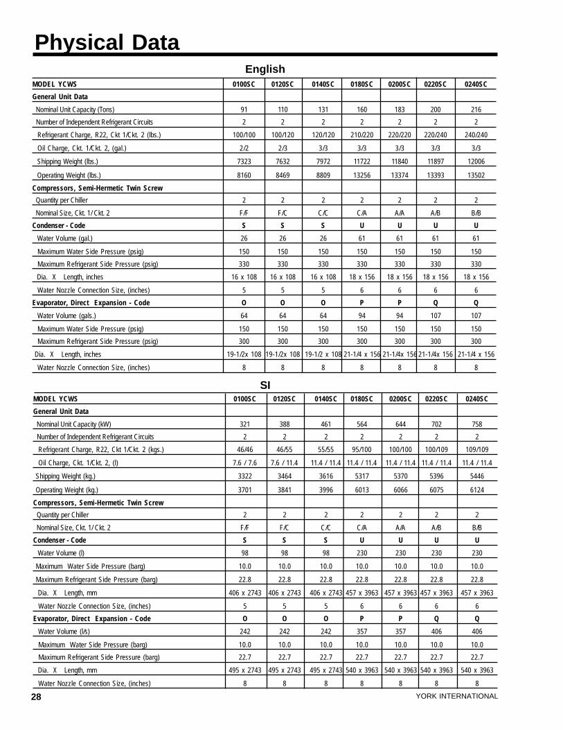
Physical Data
MODEL YCWS 0100SC 0120SC 0140SC 0180SC 0200SC 0220SC 0240SC
General Unit Data
Nominal Unit Capacity (Tons) 91 110 131 160 183 200 216
Number of Independent Refrigerant Circuits 2 2 2 2 2 2 2
Refrigerant Charge, R22, Ckt 1/Ckt. 2 (lbs.) 100/100 100/120 120/120 210/220 220/220 220/240 240/240
Oil Charge, Ckt. 1/Ckt. 2, (gal.) 2/2 2/3 3/3 3/3 3/3 3/3 3/3
Shipping Weight (lbs.) 7323 7632 7972 11722 11840 11897 12006
Operating Weight (lbs.) 8160 8469 8809 13256 13374 13393 13502
Compressors, Semi-Hermetic Twin Screw
Quantity per Chiller 2 2 2 2 2 2 2
Nominal Size, Ckt. 1/ Ckt. 2 F/F F/C C/C C/A A/A A/B B/B
Condenser - Code S S S U U U U
Water Volume (gal.) 26 26 26 61 61 61 61
Maximum Water Side Pressure (psig) 150 150 150 150 150 150 150
Maximum Refrigerant Side Pressure (psig) 330 330 330 330 330 330 330
Dia. X Length, inches 16 x 108 16 x 108 16 x 108 18 x 156 18 x 156 18 x 156 18 x 156
Water Nozzle Connection Size, (inches) 5 5 5 6 6 6 6
Evaporator, Direct Expansion - Code O O O P P Q Q
Water Volume (gals.) 64 64 64 94 94 107 107
Maximum Water Side Pressure (psig) 150 150 150 150 150 150 150
Maximum Refrigerant Side Pressure (psig) 300 300 300 300 300 300 300
Dia. X Length, inches 19-1/2x 108 19-1/2x 108 19-1/2 x 108 21-1/4 x 156 21-1/4x 156 21-1/4x 156 21-1/4 x 156
Water Nozzle Connection Size, (inches) 8 8 8 8 8 8 8
English
MODEL YCWS 0100SC 0120SC 0140SC 0180SC 0200SC 0220SC 0240SC
General Unit Data
Nominal Unit Capacity (kW) 321 388 461 564 644 702 758
Number of Independent Refrigerant Circuits 2 2 2 2 2 2 2
Refrigerant Charge, R22, Ckt 1/Ckt. 2 (kgs.) 46/46 46/55 55/55 95/100 100/100 100/109 109/109
Oil Charge, Ckt. 1/Ckt. 2, (l) 7.6 / 7.6 7.6 / 11.4 11.4 / 11.4 11.4 / 11.4 11.4 / 11.4 11.4 / 11.4 11.4 / 11.4
Shipping Weight (kg.) 3322 3464 3616 5317 5370 5396 5446
Operating Weight (kg.) 3701 3841 3996 6013 6066 6075 6124
Compressors, Semi-Hermetic Twin Screw
Quantity per Chiller 2 2 2 2 2 2 2
Nominal Size, Ckt. 1/ Ckt. 2 F/F F/C C/C C/A A/A A/B B/B
Condenser - Code S S S U U U U
Water Volume (l) 98 98 98 230 230 230 230
Maximum Water Side Pressure (barg) 10.0 10.0 10.0 10.0 10.0 10.0 10.0
Maximum Refrigerant Side Pressure (barg) 22.8 22.8 22.8 22.8 22.8 22.8 22.8
Dia. X Length, mm 406 x 2743 406 x 2743 406 x 2743 457 x 3963 457 x 3963 457 x 3963 457 x 3963
Water Nozzle Connection Size, (inches) 5 5 5 6 6 6 6
Evaporator, Direct Expansion - Code O O O P P Q Q
Water Volume (l/s) 242 242 242 357 357 406 406
Maximum Water Side Pressure (barg) 10.0 10.0 10.0 10.0 10.0 10.0 10.0
Maximum Refrigerant Side Pressure (barg) 22.7 22.7 22.7 22.7 22.7 22.7 22.7
Dia. X Length, mm 495 x 2743 495 x 2743 495 x 2743 540 x 3963 540 x 3963 540 x 3963 540 x 3963
Water Nozzle Connection Size, (inches) 8 8 8 8 8 8 8
SI
FORM 201.24-EG1
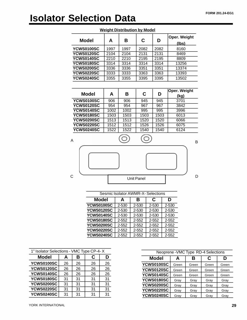
29YORK INTERNATIONAL
A B
C Unit Panel D
Weight Distribution by Model
1" Isolator Selections - VMC Type CP-4- X
Model A B C DYCWS0100SC 26 26 26 26YCWS0120SC 26 26 26 26YCWS0140SC 26 26 26 26YCWS0180SC 31 31 31 31YCWS0200SC 31 31 31 31YCWS0220SC 31 31 31 31YCWS0240SC 31 31 31 31
Isolator Selection Data
Neoprene -VMC Type RD-4 Selections
Model A B C DYCWS0100SC Green Green Green Green
YCWS0120SC Green Green Green Green
YCWS0140SC Green Green Green Green
YCWS0180SC Gray Gray Gray Gray
YCWS0200SC Gray Gray Gray Gray
YCWS0220SC Gray Gray Gray Gray
YCWS0240SC Gray Gray Gray Gray
Model A B C DOper. Weight
(kg)YCWS0100SC 906 906 945 945 3701YCWS0120SC 954 954 967 967 3842YCWS0140SC 1002 1002 995 995 3996YCWS0180SC 1503 1503 1503 1503 6013YCWS0200SC 1513 1513 1520 1520 6066YCWS0220SC 1512 1512 1526 1526 6075YCWS0240SC 1522 1522 1540 1540 6124
Model A B C DOper. Weight
(lbs)YCWS0100SC 1997 1997 2082 2082 8160YCWS0120SC 2104 2104 2131 2131 8469YCWS0140SC 2210 2210 2195 2195 8809YCWS0180SC 3314 3314 3314 3314 13256YCWS0200SC 3336 3336 3351 3351 13374YCWS0220SC 3333 3333 3363 3363 13393YCWS0240SC 3355 3355 3395 3395 13502
Sesmic Isolator AWMR-X- Selections
Model A B C DYCWS0100SC 2-530 2-530 2-530 2-530YCWS0120SC 2-530 2-530 2-530 2-530YCWS0140SC 2-530 2-530 2-530 2-530YCWS0180SC 2-552 2-552 2-552 2-552YCWS0200SC 2-552 2-552 2-552 2-552YCWS0220SC 2-552 2-552 2-552 2-552YCWS0240SC 2-552 2-552 2-552 2-552
30 YORK INTERNATIONAL
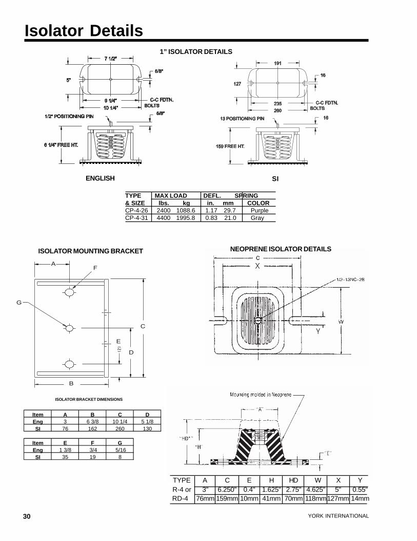
Isolator Details1” ISOLATOR DETAILS
NEOPRENE ISOLATOR DETAILS
TYPE MAX LOAD DEFL. SPRING& SIZE lbs. kg in. mm COLORCP-4-26 2400 1088.6 1.17 29.7 PurpleCP-4-31 4400 1995.8 0.83 21.0 Gray
ENGLISH SI
A
B
C
D
E
F
G
ISOLATOR MOUNTING BRACKET
TYPE A C E H HD W X Y R-4 or 3" 6.250" 0.4" 1.625" 2.75" 4.625" 5" 0.55" RD-4 76mm 159mm 10mm 41mm 70mm 118mm127mm 14mm
Item A B C DEng 3 6 3/8 10 1/4 5 1/8SI 76 162 260 130
Item E F GEng 1 3/8 3/4 5/16SI 35 19 8
ISOLATOR BRACKET DIMENSIONS
FORM 201.24-EG1
31YORK INTERNATIONAL
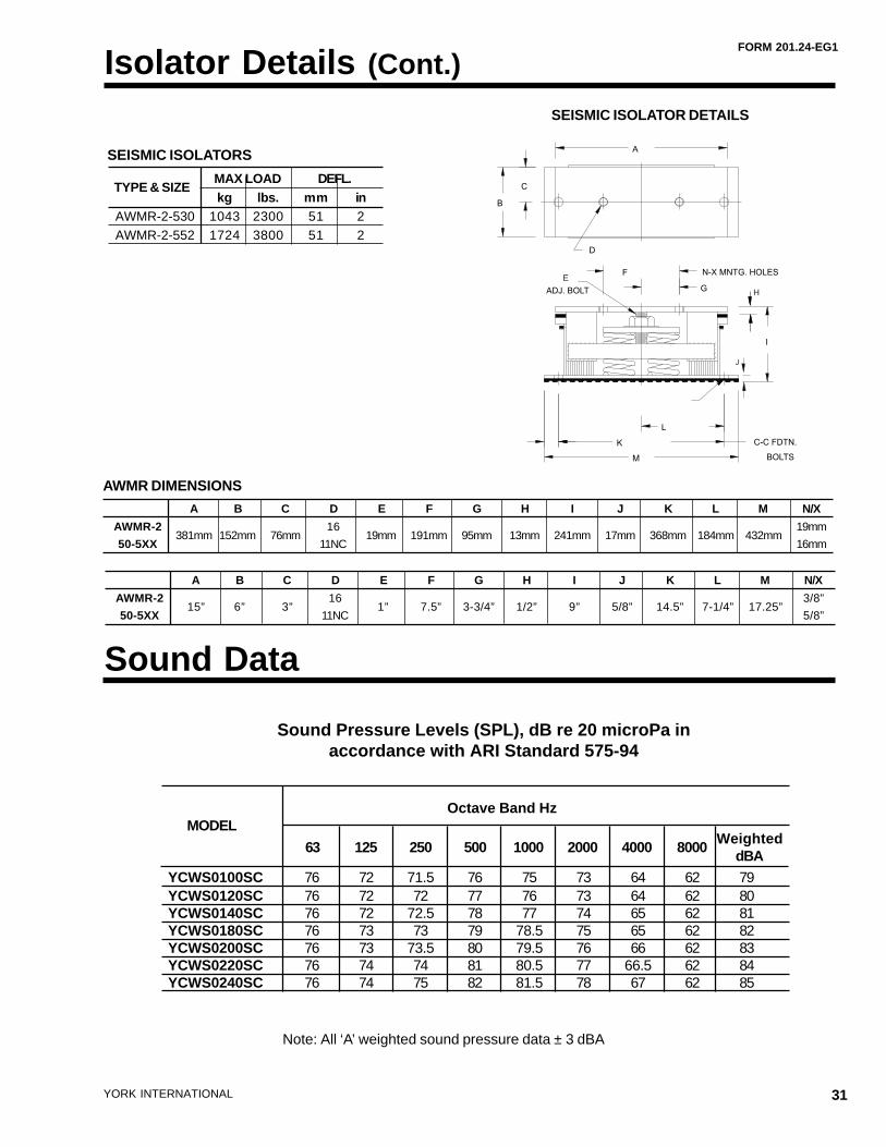
Sound Data
Sound Pressure Levels (SPL), dB re 20 microPa inaccordance with ARI Standard 575-94
Note: All ‘A’ weighted sound pressure data ± 3 dBA
MODEL
63 125 250 500 1000 2000 4000 8000Weighted
dBA YCWS0100SC 76 72 71.5 76 75 73 64 62 79 YCWS0120SC 76 72 72 77 76 73 64 62 80 YCWS0140SC 76 72 72.5 78 77 74 65 62 81 YCWS0180SC 76 73 73 79 78.5 75 65 62 82 YCWS0200SC 76 73 73.5 80 79.5 76 66 62 83 YCWS0220SC 76 74 74 81 80.5 77 66.5 62 84 YCWS0240SC 76 74 75 82 81.5 78 67 62 85
Octave Band Hz
Isolator Details (Cont.)
TYPE & SIZEMAX LOAD DEFL.kg lbs. mm in
AWMR-2-530 1043 2300 51 2AWMR-2-552 1724 3800 51 2
SEISMIC ISOLATORS
A B C D E F G H I J K L M N/X
AWMR-2381mm 152mm 76mm
1619mm 191mm 95mm 13mm 241mm 17mm 368mm 184mm 432mm
19mm
50-5XX 11NC 16mm
AWMR DIMENSIONS
A B C D E F G H I J K L M N/X
AWMR-215” 6” 3”
161” 7.5” 3-3/4” 1/2” 9” 5/8” 14.5” 7-1/4” 17.25”
3/8”
50-5XX 11NC 5/8”
SEISMIC ISOLATOR DETAILS
E
H
J
N-X MNTG. HOLES
D
ADJ. BOLT
A
I
C-C FDTN.
BOLTS
C
B
F
G
M
K
L
32 YORK INTERNATIONAL
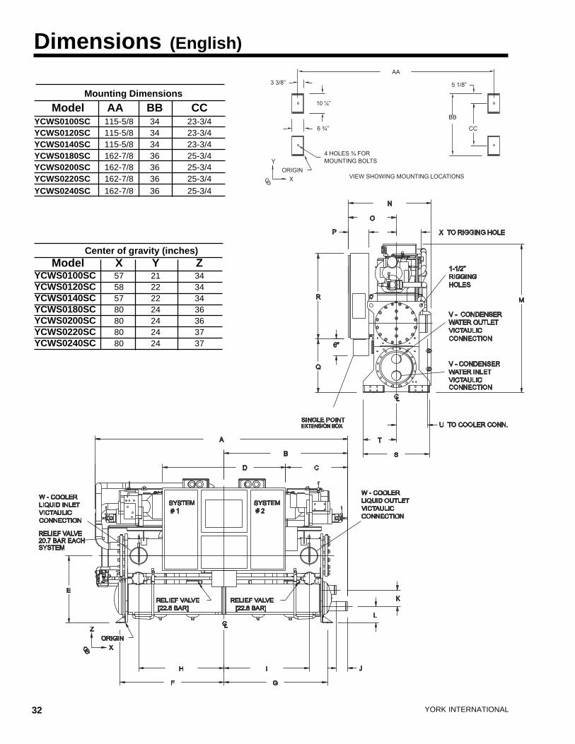
Dimensions (English)
Center of gravity (inches) Model X Y Z
YCWS0100SC 57 21 34YCWS0120SC 58 22 34YCWS0140SC 57 22 34YCWS0180SC 80 24 36YCWS0200SC 80 24 36YCWS0220SC 80 24 37YCWS0240SC 80 24 37
Mounting Dimensions
Model AA BB CCYCWS0100SC 115-5/8 34 23-3/4YCWS0120SC 115-5/8 34 23-3/4YCWS0140SC 115-5/8 34 23-3/4YCWS0180SC 162-7/8 36 25-3/4YCWS0200SC 162-7/8 36 25-3/4YCWS0220SC 162-7/8 36 25-3/4YCWS0240SC 162-7/8 36 25-3/4
FORM 201.24-EG1
33YORK INTERNATIONAL
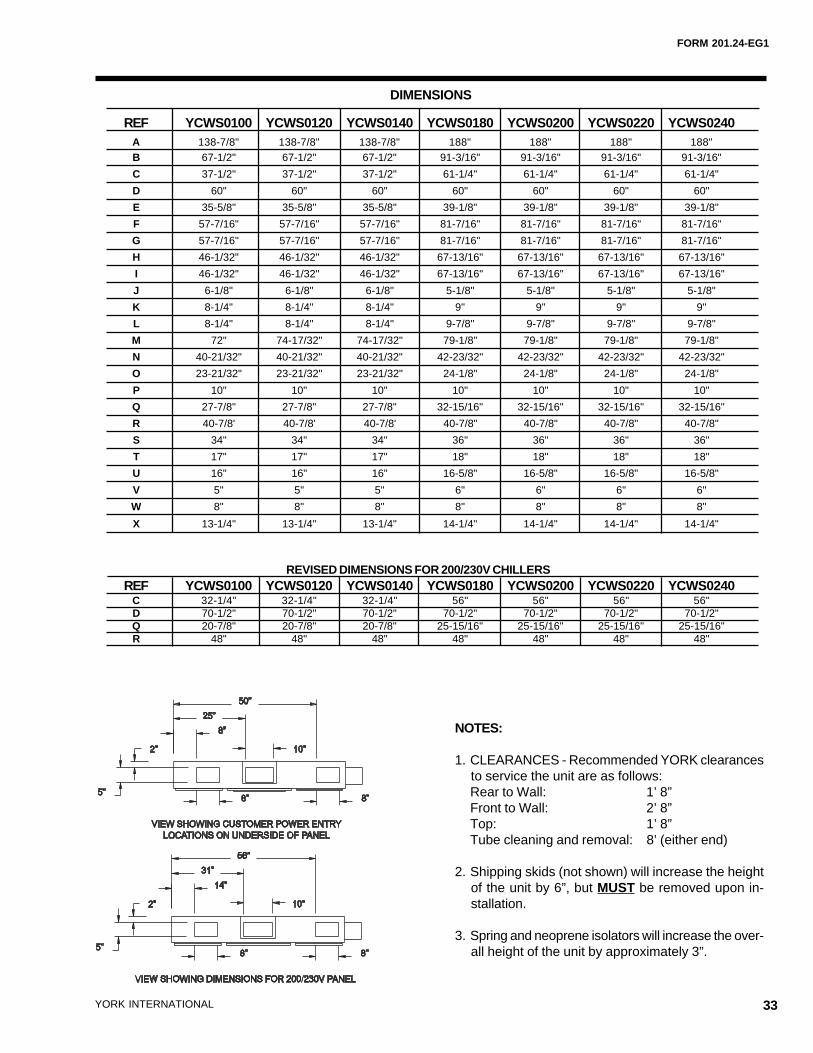
DIMENSIONS
NOTES:
1. CLEARANCES - Recommended YORK clearancesto service the unit are as follows:Rear to Wall: 1’ 8”Front to Wall: 2’ 8”Top: 1’ 8”Tube cleaning and removal: 8’ (either end)
2. Shipping skids (not shown) will increase the heightof the unit by 6”, but MUST be removed upon in-stallation.
3. Spring and neoprene isolators will increase the over-all height of the unit by approximately 3”.
REF YCWS0100 YCWS0120 YCWS0140 YCWS0180 YCWS0200 YCWS0220 YCWS0240A 138-7/8" 138-7/8" 138-7/8" 188" 188" 188" 188"B 67-1/2" 67-1/2" 67-1/2" 91-3/16" 91-3/16" 91-3/16" 91-3/16"
C 37-1/2" 37-1/2" 37-1/2" 61-1/4" 61-1/4" 61-1/4" 61-1/4"
D 60" 60" 60" 60" 60" 60" 60"
E 35-5/8" 35-5/8" 35-5/8" 39-1/8" 39-1/8" 39-1/8" 39-1/8"
F 57-7/16" 57-7/16" 57-7/16" 81-7/16" 81-7/16" 81-7/16" 81-7/16"
G 57-7/16" 57-7/16" 57-7/16" 81-7/16" 81-7/16" 81-7/16" 81-7/16"
H 46-1/32" 46-1/32" 46-1/32" 67-13/16" 67-13/16" 67-13/16" 67-13/16"
I 46-1/32" 46-1/32" 46-1/32" 67-13/16" 67-13/16" 67-13/16" 67-13/16"
J 6-1/8" 6-1/8" 6-1/8" 5-1/8" 5-1/8" 5-1/8" 5-1/8"
K 8-1/4" 8-1/4" 8-1/4" 9" 9" 9" 9"
L 8-1/4" 8-1/4" 8-1/4" 9-7/8" 9-7/8" 9-7/8" 9-7/8"
M 72" 74-17/32" 74-17/32" 79-1/8" 79-1/8" 79-1/8" 79-1/8"
N 40-21/32" 40-21/32" 40-21/32" 42-23/32" 42-23/32" 42-23/32" 42-23/32"
O 23-21/32" 23-21/32" 23-21/32" 24-1/8" 24-1/8" 24-1/8" 24-1/8"
P 10" 10" 10" 10" 10" 10" 10"
Q 27-7/8" 27-7/8" 27-7/8" 32-15/16" 32-15/16" 32-15/16" 32-15/16"
R 40-7/8' 40-7/8' 40-7/8' 40-7/8" 40-7/8" 40-7/8" 40-7/8"
S 34" 34" 34" 36" 36" 36" 36"
T 17" 17" 17" 18" 18" 18" 18"
U 16" 16" 16" 16-5/8" 16-5/8" 16-5/8" 16-5/8"
V 5" 5" 5" 6" 6" 6" 6"
W 8" 8" 8" 8" 8" 8" 8"
X 13-1/4" 13-1/4" 13-1/4" 14-1/4" 14-1/4" 14-1/4" 14-1/4"
REVISED DIMENSIONS FOR 200/230V CHILLERSREF YCWS0100 YCWS0120 YCWS0140 YCWS0180 YCWS0200 YCWS0220 YCWS0240
C 32-1/4" 32-1/4" 32-1/4" 56" 56" 56" 56"D 70-1/2" 70-1/2" 70-1/2" 70-1/2" 70-1/2" 70-1/2" 70-1/2"Q 20-7/8" 20-7/8" 20-7/8" 25-15/16" 25-15/16" 25-15/16" 25-15/16"R 48" 48" 48" 48" 48" 48" 48"
34 YORK INTERNATIONAL
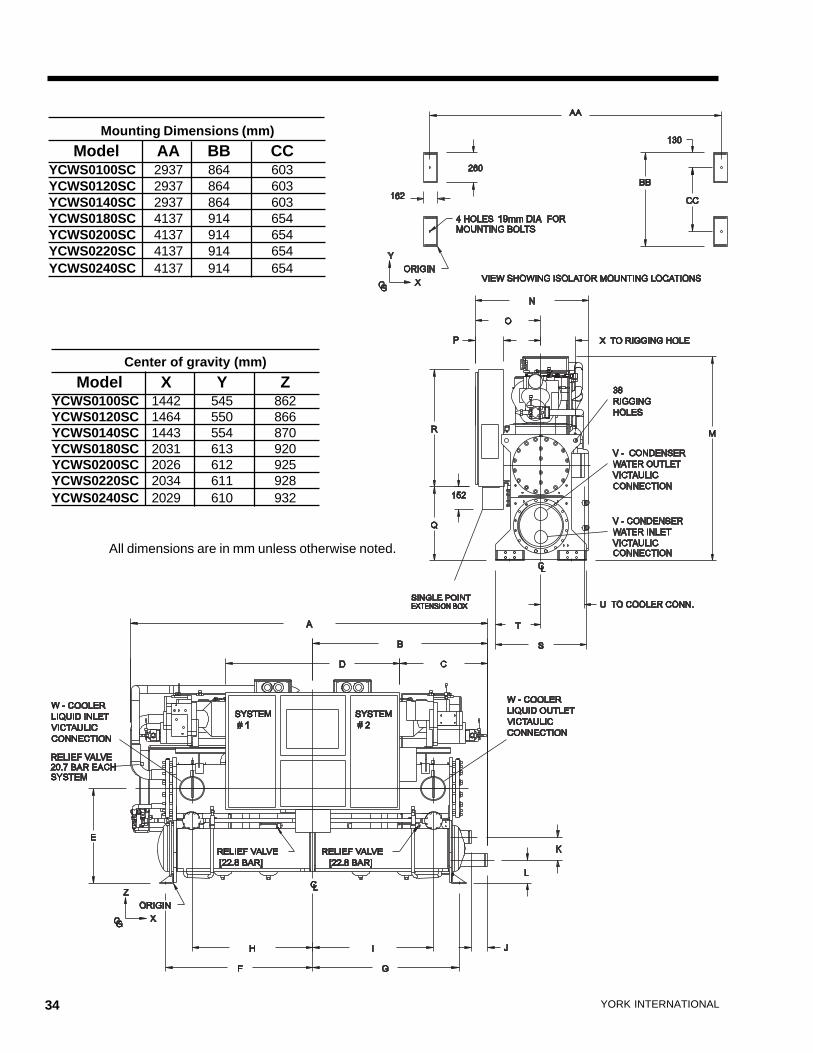
All dimensions are in mm unless otherwise noted.
Mounting Dimensions (mm)
Model AA BB CCYCWS0100SC 2937 864 603YCWS0120SC 2937 864 603YCWS0140SC 2937 864 603YCWS0180SC 4137 914 654YCWS0200SC 4137 914 654YCWS0220SC 4137 914 654YCWS0240SC 4137 914 654
Center of gravity (mm)
Model X Y ZYCWS0100SC 1442 545 862YCWS0120SC 1464 550 866YCWS0140SC 1443 554 870YCWS0180SC 2031 613 920YCWS0200SC 2026 612 925YCWS0220SC 2034 611 928YCWS0240SC 2029 610 932
FORM 201.24-EG1
35YORK INTERNATIONAL
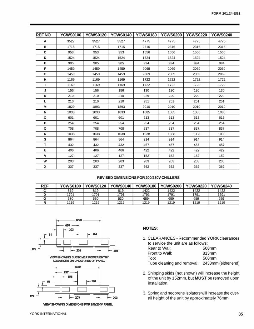
NOTES:
1. CLEARANCES - Recommended YORK clearancesto service the unit are as follows:Rear to Wall: 508mmFront to Wall: 813mmTop: 508mmTube cleaning and removal: 2438mm (either end)
2. Shipping skids (not shown) will increase the heightof the unit by 152mm, but MUST be removed uponinstallation.
3. Spring and neoprene isolators will increase the over-all height of the unit by approximately 76mm.
REF NO YCWS0100 YCWS0120 YCWS0140 YCWS0180 YCWS0200 YCWS0220 YCWS0240A 3527 3527 3527 4775 4775 4775 4775
B 1715 1715 1715 2316 2316 2316 2316
C 953 953 953 1556 1556 1556 1556
D 1524 1524 1524 1524 1524 1524 1524
E 905 905 905 994 994 994 994
F 1459 1459 1459 2069 2069 2069 2069
G 1459 1459 1459 2069 2069 2069 2069
H 1169 1169 1169 1722 1722 1722 1722
I 1169 1169 1169 1722 1722 1722 1722
J 156 156 156 130 130 130 130
K 210 210 210 229 229 229 229
L 210 210 210 251 251 251 251
M 1829 1893 1893 2010 2010 2010 2010
N 1033 1033 1033 1085 1085 1085 1085
O 601 601 601 613 613 613 613
P 254 254 254 254 254 254 254
Q 708 708 708 837 837 837 837
R 1038 1038 1038 1038 1038 1038 1038
S 864 864 864 914 914 914 914
T 432 432 432 457 457 457 457
U 406 406 406 422 422 422 422
V 127 127 127 152 152 152 152
W 203 203 203 203 203 203 203
X 337 337 337 362 362 362 362
REVISED DIMENSIONS FOR 200/230V CHILLERS
REF YCWS0100 YCWS0120 YCWS0140 YCWS0180 YCWS0200 YCWS0220 YCWS0240C 819 819 819 1422 1422 1422 1422D 1791 1791 1791 1791 1791 1791 1791Q 530 530 530 659 659 659 659R 1219 1219 1219 1219 1219 1219 1219
36 YORK INTERNATIONAL
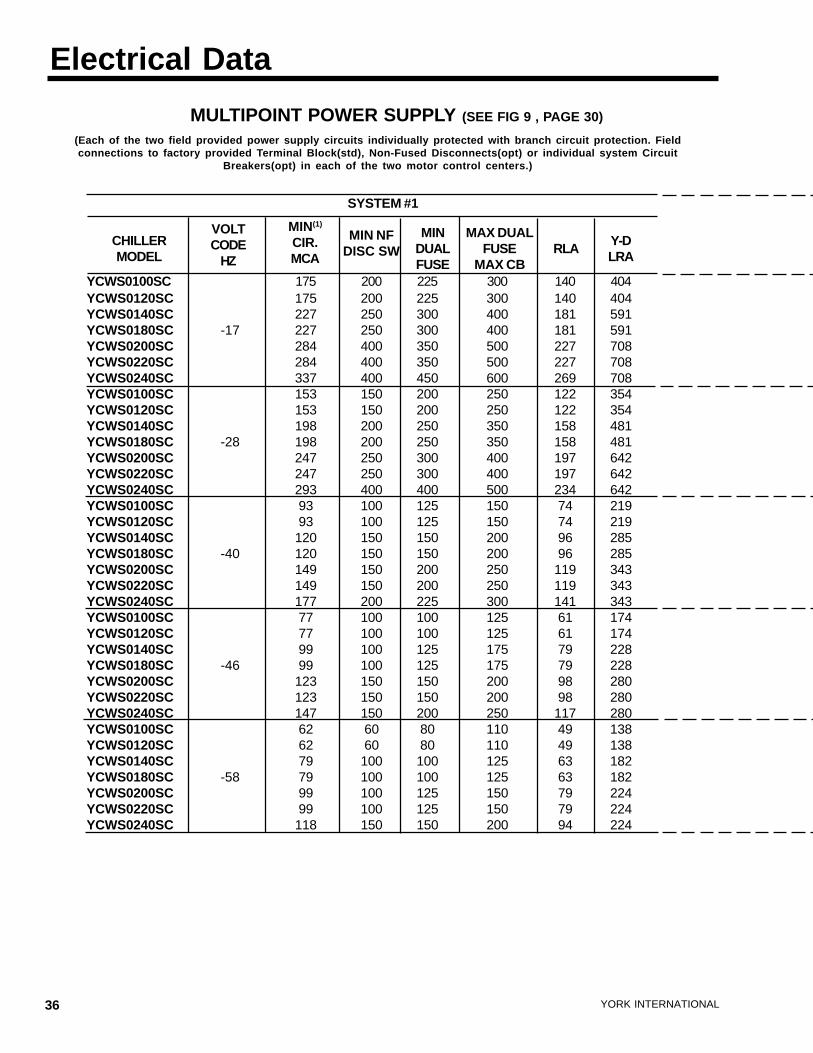
Electrical Data
MULTIPOINT POWER SUPPLY (SEE FIG 9 , PAGE 30)
SYSTEM #1
(Each of the two field provided power supply circuits individually protected with branch circuit protection. Fieldconnections to factory provided Terminal Block(std), Non-Fused Disconnects(opt) or individual system Circuit
Breakers(opt) in each of the two motor control centers.)
YCWS0100SC 175 200 225 300 140 404YCWS0120SC 175 200 225 300 140 404YCWS0140SC 227 250 300 400 181 591YCWS0180SC -17 227 250 300 400 181 591YCWS0200SC 284 400 350 500 227 708YCWS0220SC 284 400 350 500 227 708YCWS0240SC 337 400 450 600 269 708YCWS0100SC 153 150 200 250 122 354YCWS0120SC 153 150 200 250 122 354YCWS0140SC 198 200 250 350 158 481YCWS0180SC -28 198 200 250 350 158 481YCWS0200SC 247 250 300 400 197 642YCWS0220SC 247 250 300 400 197 642YCWS0240SC 293 400 400 500 234 642YCWS0100SC 93 100 125 150 74 219YCWS0120SC 93 100 125 150 74 219YCWS0140SC 120 150 150 200 96 285YCWS0180SC -40 120 150 150 200 96 285YCWS0200SC 149 150 200 250 119 343YCWS0220SC 149 150 200 250 119 343YCWS0240SC 177 200 225 300 141 343YCWS0100SC 77 100 100 125 61 174YCWS0120SC 77 100 100 125 61 174YCWS0140SC 99 100 125 175 79 228YCWS0180SC -46 99 100 125 175 79 228YCWS0200SC 123 150 150 200 98 280YCWS0220SC 123 150 150 200 98 280YCWS0240SC 147 150 200 250 117 280YCWS0100SC 62 60 80 110 49 138YCWS0120SC 62 60 80 110 49 138YCWS0140SC 79 100 100 125 63 182YCWS0180SC -58 79 100 100 125 63 182YCWS0200SC 99 100 125 150 79 224YCWS0220SC 99 100 125 150 79 224YCWS0240SC 118 150 150 200 94 224
CHILLERMODEL
VOLTCODE
HZ
MIN NFDISC SW
MIN(1)
CIR.MCA
MINDUALFUSE
MAX DUALFUSE
MAX CBRLA
Y-DLRA
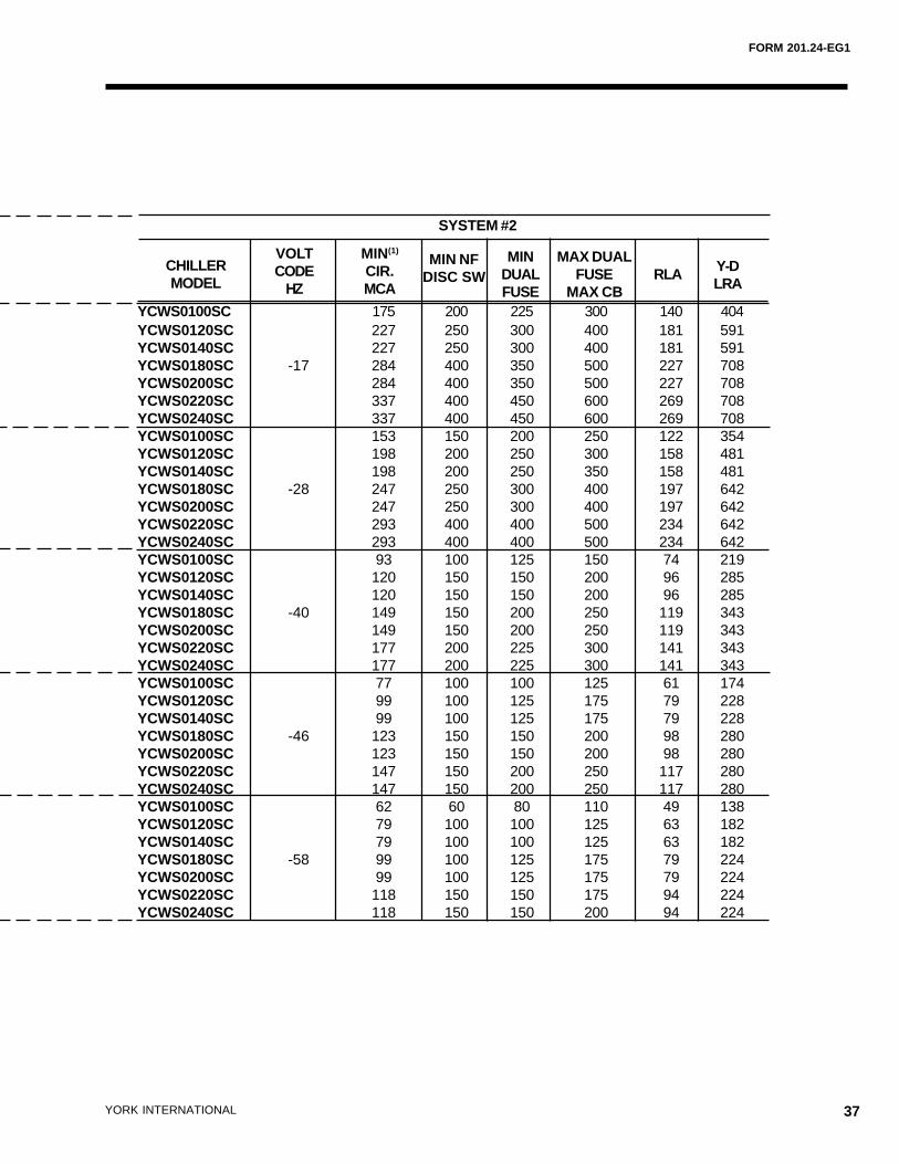
FORM 201.24-EG1
37YORK INTERNATIONAL
YCWS0100SC 175 200 225 300 140 404YCWS0120SC 227 250 300 400 181 591YCWS0140SC 227 250 300 400 181 591YCWS0180SC -17 284 400 350 500 227 708YCWS0200SC 284 400 350 500 227 708YCWS0220SC 337 400 450 600 269 708YCWS0240SC 337 400 450 600 269 708YCWS0100SC 153 150 200 250 122 354YCWS0120SC 198 200 250 300 158 481YCWS0140SC 198 200 250 350 158 481YCWS0180SC -28 247 250 300 400 197 642YCWS0200SC 247 250 300 400 197 642YCWS0220SC 293 400 400 500 234 642YCWS0240SC 293 400 400 500 234 642YCWS0100SC 93 100 125 150 74 219YCWS0120SC 120 150 150 200 96 285YCWS0140SC 120 150 150 200 96 285YCWS0180SC -40 149 150 200 250 119 343YCWS0200SC 149 150 200 250 119 343YCWS0220SC 177 200 225 300 141 343YCWS0240SC 177 200 225 300 141 343YCWS0100SC 77 100 100 125 61 174YCWS0120SC 99 100 125 175 79 228YCWS0140SC 99 100 125 175 79 228YCWS0180SC -46 123 150 150 200 98 280YCWS0200SC 123 150 150 200 98 280YCWS0220SC 147 150 200 250 117 280YCWS0240SC 147 150 200 250 117 280YCWS0100SC 62 60 80 110 49 138YCWS0120SC 79 100 100 125 63 182YCWS0140SC 79 100 100 125 63 182YCWS0180SC -58 99 100 125 175 79 224YCWS0200SC 99 100 125 175 79 224YCWS0220SC 118 150 150 175 94 224YCWS0240SC 118 150 150 200 94 224
MINDUALFUSE
MAX DUALFUSE
MAX CB
CHILLERMODEL
VOLTCODE
HZ
MIN(1)
CIR.MCA
RLA Y-DLRA
SYSTEM #2
MIN NFDISC SW
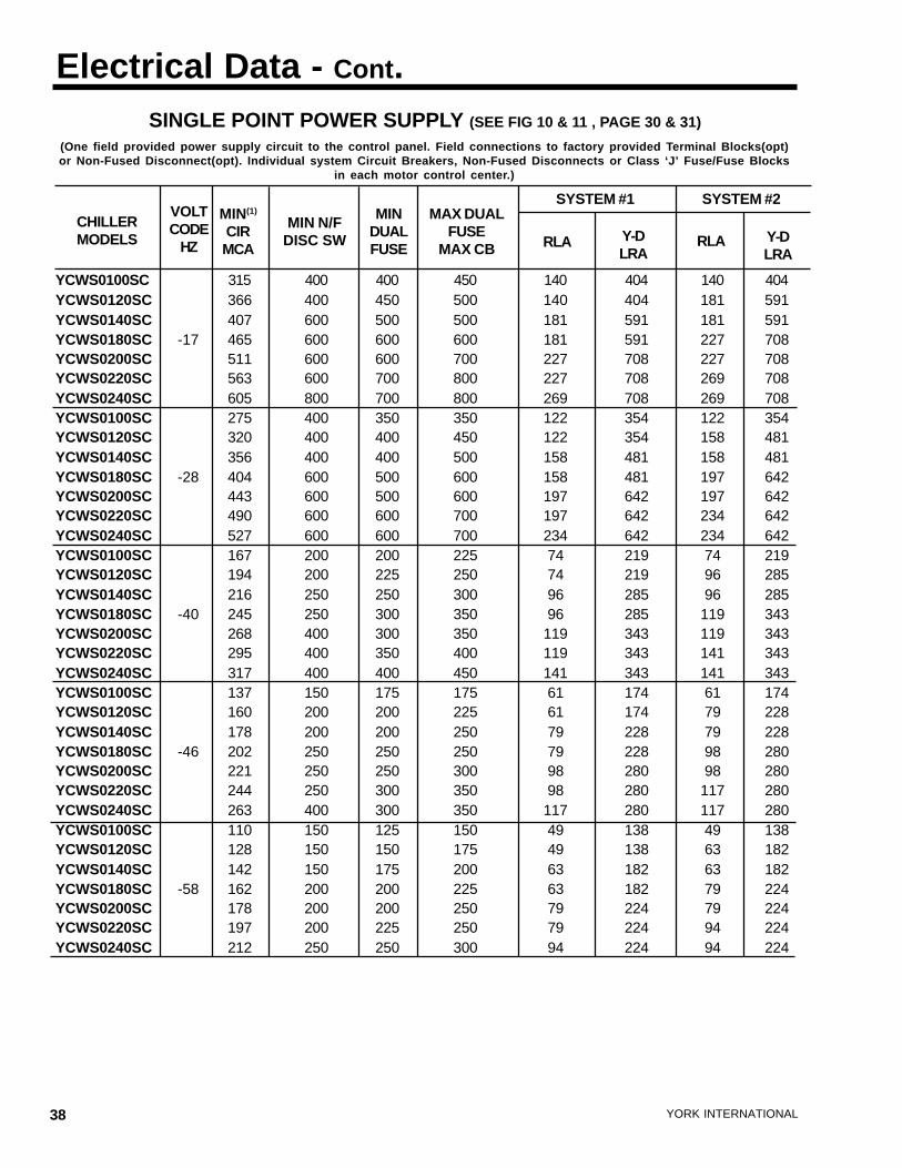
38 YORK INTERNATIONAL
Electrical Data - Cont.SINGLE POINT POWER SUPPLY (SEE FIG 10 & 11 , PAGE 30 & 31)
(One field provided power supply circuit to the control panel. Field connections to factory provided Terminal Blocks(opt)or Non-Fused Disconnect(opt). Individual system Circuit Breakers, Non-Fused Disconnects or Class ‘J’ Fuse/Fuse Blocks
in each motor control center.)
YCWS0100SC 315 400 400 450 140 404 140 404YCWS0120SC 366 400 450 500 140 404 181 591YCWS0140SC 407 600 500 500 181 591 181 591YCWS0180SC -17 465 600 600 600 181 591 227 708YCWS0200SC 511 600 600 700 227 708 227 708YCWS0220SC 563 600 700 800 227 708 269 708YCWS0240SC 605 800 700 800 269 708 269 708YCWS0100SC 275 400 350 350 122 354 122 354YCWS0120SC 320 400 400 450 122 354 158 481YCWS0140SC 356 400 400 500 158 481 158 481YCWS0180SC -28 404 600 500 600 158 481 197 642YCWS0200SC 443 600 500 600 197 642 197 642YCWS0220SC 490 600 600 700 197 642 234 642YCWS0240SC 527 600 600 700 234 642 234 642YCWS0100SC 167 200 200 225 74 219 74 219YCWS0120SC 194 200 225 250 74 219 96 285YCWS0140SC 216 250 250 300 96 285 96 285YCWS0180SC -40 245 250 300 350 96 285 119 343YCWS0200SC 268 400 300 350 119 343 119 343YCWS0220SC 295 400 350 400 119 343 141 343YCWS0240SC 317 400 400 450 141 343 141 343YCWS0100SC 137 150 175 175 61 174 61 174YCWS0120SC 160 200 200 225 61 174 79 228YCWS0140SC 178 200 200 250 79 228 79 228YCWS0180SC -46 202 250 250 250 79 228 98 280YCWS0200SC 221 250 250 300 98 280 98 280YCWS0220SC 244 250 300 350 98 280 117 280YCWS0240SC 263 400 300 350 117 280 117 280YCWS0100SC 110 150 125 150 49 138 49 138YCWS0120SC 128 150 150 175 49 138 63 182YCWS0140SC 142 150 175 200 63 182 63 182YCWS0180SC -58 162 200 200 225 63 182 79 224YCWS0200SC 178 200 200 250 79 224 79 224YCWS0220SC 197 200 225 250 79 224 94 224YCWS0240SC 212 250 250 300 94 224 94 224
CHILLERMODELS
VOLTCODE
HZ
MIN(1)
CIRMCA
MIN N/FDISC SW
MINDUALFUSE
MAX DUALFUSE
MAX CB RLA Y-DLRA
RLA Y-DLRA
SYSTEM #1 SYSTEM #2
FORM 201.24-EG1
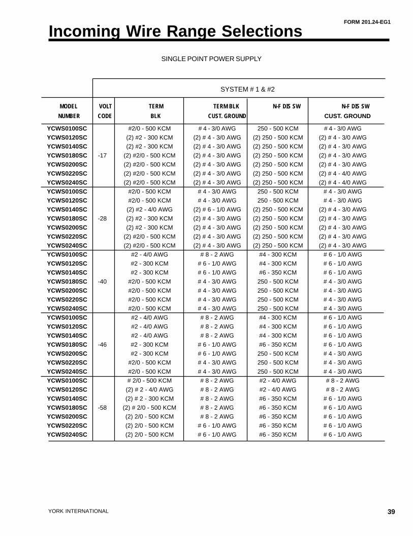
39YORK INTERNATIONAL
Incoming Wire Range Selections
MODEL VOLT TERM TERM BLK N-F DIS SW N-F DIS SW
NUMBER CODE BLK CUST. GROUND CUST. GROUND
SYSTEM # 1 & #2
YCWS0100SC #2/0 - 500 KCM # 4 - 3/0 AWG 250 - 500 KCM # 4 - 3/0 AWG
YCWS0120SC (2) #2 - 300 KCM (2) # 4 - 3/0 AWG (2) 250 - 500 KCM (2) # 4 - 3/0 AWG
YCWS0140SC (2) #2 - 300 KCM (2) # 4 - 3/0 AWG (2) 250 - 500 KCM (2) # 4 - 3/0 AWG
YCWS0180SC -17 (2) #2/0 - 500 KCM (2) # 4 - 3/0 AWG (2) 250 - 500 KCM (2) # 4 - 3/0 AWG
YCWS0200SC (2) #2/0 - 500 KCM (2) # 4 - 3/0 AWG (2) 250 - 500 KCM (2) # 4 - 3/0 AWG
YCWS0220SC (2) #2/0 - 500 KCM (2) # 4 - 3/0 AWG (2) 250 - 500 KCM (2) # 4 - 4/0 AWG
YCWS0240SC (2) #2/0 - 500 KCM (2) # 4 - 3/0 AWG (2) 250 - 500 KCM (2) # 4 - 4/0 AWG
YCWS0100SC #2/0 - 500 KCM # 4 - 3/0 AWG 250 - 500 KCM # 4 - 3/0 AWG
YCWS0120SC #2/0 - 500 KCM # 4 - 3/0 AWG 250 - 500 KCM # 4 - 3/0 AWG
YCWS0140SC (2) #2 - 4/0 AWG (2) # 6 - 1/0 AWG (2) 250 - 500 KCM (2) # 4 - 3/0 AWG
YCWS0180SC -28 (2) #2 - 300 KCM (2) # 4 - 3/0 AWG (2) 250 - 500 KCM (2) # 4 - 3/0 AWG
YCWS0200SC (2) #2 - 300 KCM (2) # 4 - 3/0 AWG (2) 250 - 500 KCM (2) # 4 - 3/0 AWG
YCWS0220SC (2) #2/0 - 500 KCM (2) # 4 - 3/0 AWG (2) 250 - 500 KCM (2) # 4 - 3/0 AWG
YCWS0240SC (2) #2/0 - 500 KCM (2) # 4 - 3/0 AWG (2) 250 - 500 KCM (2) # 4 - 3/0 AWG
YCWS0100SC #2 - 4/0 AWG # 8 - 2 AWG #4 - 300 KCM # 6 - 1/0 AWG
YCWS0120SC #2 - 300 KCM # 6 - 1/0 AWG #4 - 300 KCM # 6 - 1/0 AWG
YCWS0140SC #2 - 300 KCM # 6 - 1/0 AWG #6 - 350 KCM # 6 - 1/0 AWG
YCWS0180SC -40 #2/0 - 500 KCM # 4 - 3/0 AWG 250 - 500 KCM # 4 - 3/0 AWG
YCWS0200SC #2/0 - 500 KCM # 4 - 3/0 AWG 250 - 500 KCM # 4 - 3/0 AWG
YCWS0220SC #2/0 - 500 KCM # 4 - 3/0 AWG 250 - 500 KCM # 4 - 3/0 AWG
YCWS0240SC #2/0 - 500 KCM # 4 - 3/0 AWG 250 - 500 KCM # 4 - 3/0 AWG
YCWS0100SC #2 - 4/0 AWG # 8 - 2 AWG #4 - 300 KCM # 6 - 1/0 AWG
YCWS0120SC #2 - 4/0 AWG # 8 - 2 AWG #4 - 300 KCM # 6 - 1/0 AWG
YCWS0140SC #2 - 4/0 AWG # 8 - 2 AWG #4 - 300 KCM # 6 - 1/0 AWG
YCWS0180SC -46 #2 - 300 KCM # 6 - 1/0 AWG #6 - 350 KCM # 6 - 1/0 AWG
YCWS0200SC #2 - 300 KCM # 6 - 1/0 AWG 250 - 500 KCM # 4 - 3/0 AWG
YCWS0220SC #2/0 - 500 KCM # 4 - 3/0 AWG 250 - 500 KCM # 4 - 3/0 AWG
YCWS0240SC #2/0 - 500 KCM # 4 - 3/0 AWG 250 - 500 KCM # 4 - 3/0 AWG
YCWS0100SC # 2/0 - 500 KCM # 8 - 2 AWG #2 - 4/0 AWG # 8 - 2 AWG
YCWS0120SC (2) # 2 - 4/0 AWG # 8 - 2 AWG #2 - 4/0 AWG # 8 - 2 AWG
YCWS0140SC (2) # 2 - 300 KCM # 8 - 2 AWG #6 - 350 KCM # 6 - 1/0 AWG
YCWS0180SC -58 (2) # 2/0 - 500 KCM # 8 - 2 AWG #6 - 350 KCM # 6 - 1/0 AWG
YCWS0200SC (2) 2/0 - 500 KCM # 8 - 2 AWG #6 - 350 KCM # 6 - 1/0 AWG
YCWS0220SC (2) 2/0 - 500 KCM # 6 - 1/0 AWG #6 - 350 KCM # 6 - 1/0 AWG
YCWS0240SC (2) 2/0 - 500 KCM # 6 - 1/0 AWG #6 - 350 KCM # 6 - 1/0 AWG
SINGLE POINT POWER SUPPLY
40 YORK INTERNATIONAL
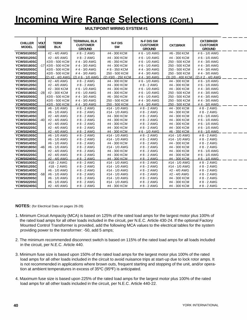
Incoming Wire Range Selections (Cont.)MULTIPOINT WIRING SYSTEM #1
YCWS0100SC #2 - 4/0 AWG # 8 - 2 AWG #4 - 300 KCM # 6 - 1/0 AWG #6 - 350 KCM # 6 - 1/0 AWGYCWS0120SC #2 - 4/0 AWG # 8 - 2 AWG #4 - 300 KCM # 6 - 1/0 AWG #4 - 300 KCM # 6 - 1/0 AWGYCWS0140SC #2/0 - 500 KCM # 4 - 3/0 AWG #6 - 350 KCM # 6 - 1/0 AWG 250 - 500 KCM # 4 - 3/0 AWGYCWS0180SC -17 #2/0 - 500 KCM # 4 - 3/0 AWG #4 - 300 KCM # 6 - 1/0 AWG 250 - 500 KCM # 4 - 3/0 AWGYCWS0200SC #2/0 - 500 KCM # 4 - 3/0 AWG # 8 - 350 KCM # 4 - 3/0 AWG 250 - 500 KCM # 4 - 3/0 AWGYCWS0220SC #2/0 - 500 KCM # 4 - 3/0 AWG 250 - 500 KCM # 4 - 3/0 AWG 250 - 500 KCM # 4 - 3/0 AWGYCWS0240SC (2) #2 - 4/0 AWG (2) # 6 - 1/0 AWG (2) #3/0 - 250 KCM # 4 - 3/0 AWG (3) 2/0 - 400 KCM (2) # 2 - 4/0 AWGYCWS0100SC #2 - 4/0 AWG # 8 - 2 AWG #4 - 300 KCM # 6 - 1/0 AWG #4 - 300 KCM # 6 - 1/0 AWGYCWS0120SC #2 - 4/0 AWG # 8 - 2 AWG #4 - 300 KCM # 8 - 2 AWG #4 - 300 KCM # 6 - 1/0 AWGYCWS0140SC #2 - 300 KCM # 6 - 1/0 AWG #4 - 300 KCM # 6 - 1/0 AWG #4 - 300 KCM # 4 - 3/0 AWGYCWS0180SC -28 #2 - 300 KCM # 6 - 1/0 AWG #4 - 300 KCM # 6 - 1/0 AWG 250 - 500 KCM # 4 - 3/0 AWGYCWS0200SC #2/0 - 500 KCM # 4 - 3/0 AWG #6 - 350 KCM # 6 - 1/0 AWG 250 - 500 KCM # 4 - 3/0 AWGYCWS0220SC #2/0 - 500 KCM # 4 - 3/0 AWG 250 - 500 KCM # 4 - 3/0 AWG 250 - 500 KCM # 4 - 3/0 AWGYCWS0240SC #2/0 - 500 KCM # 4 - 3/0 AWG 250 - 500 KCM # 4 - 3/0 AWG 250 - 500 KCM # 4 - 3/0 AWGYCWS0100SC #6 - 1/0 AWG # 8 - 2 AWG #14 - 1/0 AWG # 8 - 2 AWG #4 - 300 KCM # 8 - 2 AWGYCWS0120SC #6 - 1/0 AWG # 8 - 2 AWG #14 - 1/0 AWG # 8 - 2 AWG #4 - 300 KCM # 8 - 2 AWGYCWS0140SC #2 - 4/0 AWG # 8 - 2 AWG #4 - 300 KCM # 8 - 2 AWG #4 - 300 KCM # 6 - 1/0 AWGYCWS0180SC -40 #2 - 4/0 AWG # 8 - 2 AWG #4 - 300 KCM # 8 - 2 AWG #4 - 300 KCM # 6 - 1/0 AWGYCWS0200SC #2 - 4/0 AWG # 8 - 2 AWG #4 - 300 KCM # 8 - 2 AWG #4 - 300 KCM # 6 - 1/0 AWGYCWS0220SC #2 - 4/0 AWG # 8 - 2 AWG #4 - 300 KCM # 8 - 2 AWG #4 - 300 KCM # 6 - 1/0 AWGYCWS0240SC #2 - 4/0 AWG # 8 - 2 AWG #4 - 300 KCM # 6 - 1/0 AWG #6 - 350 KCM # 6 - 1/0 AWGYCWS0100SC #6 - 1/0 AWG # 8 - 2 AWG #14 - 1/0 AWG # 8 - 2 AWG #14 - 1/0 AWG # 8 - 2 AWGYCWS0120SC #6 - 1/0 AWG # 8 - 2 AWG #14 - 1/0 AWG # 8 - 2 AWG #14 - 1/0 AWG # 8 - 2 AWGYCWS0140SC #6 - 1/0 AWG # 8 - 2 AWG #4 - 300 KCM # 8 - 2 AWG #4 - 300 KCM # 8 - 2 AWGYCWS0180SC -46 #6 - 1/0 AWG # 8 - 2 AWG #14 - 1/0 AWG # 8 - 2 AWG #4 - 300 KCM # 8 - 2 AWGYCWS0200SC #2 - 4/0 AWG # 8 - 2 AWG #4 - 300 KCM # 8 - 2 AWG #4 - 300 KCM # 6 - 1/0 AWGYCWS0220SC #2 - 4/0 AWG # 8 - 2 AWG #4 - 300 KCM # 8 - 2 AWG #4 - 300 KCM # 6 - 1/0 AWGYCWS0240SC #2 - 4/0 AWG # 8 - 2 AWG #4 - 300 KCM # 8 - 2 AWG #4 - 300 KCM # 6 - 1/0 AWGYCWS0100SC #18 - 2 AWG # 8 - 2 AWG #14 - 1/0 AWG # 8 - 2 AWG #14 - 1/0 AWG # 8 - 2 AWGYCWS0120SC #18 - 2 AWG # 8 - 2 AWG #14 - 1/0 AWG # 8 - 2 AWG #14 - 1/0 AWG # 8 - 2 AWGYCWS0140SC #6 - 1/0 AWG # 8 - 2 AWG #14 - 1/0 AWG # 8 - 2 AWG #2 - 4/0 AWG # 8 - 2 AWGYCWS0180SC -58 #6 - 1/0 AWG # 8 - 2 AWG #14 - 1/0 AWG # 8 - 2 AWG #2 - 4/0 AWG # 8 - 2 AWGYCWS0200SC #6 - 1/0 AWG # 8 - 2 AWG #14 - 1/0 AWG # 8 - 2 AWG #4 - 300 KCM # 8 - 2 AWGYCWS0220SC #6 - 1/0 AWG # 8 - 2 AWG #14 - 1/0 AWG # 8 - 2 AWG #4 - 300 KCM # 8 - 2 AWGYCWS0240SC #2 - 4/0 AWG # 8 - 2 AWG #4 - 300 KCM # 8 - 2 AWG #4 - 300 KCM # 8 - 2 AWG
CHILLERMODEL
VOLTCODE
TERMBLK
TERMINAL BLKCUSTOMER
GROUND
N-F DISSW
N-F DIS SWCUSTOMER
GROUNDCKT.BRKR
CKT.BRKERCUSTOMER
GROUND
NOTES: (for Electrical Data on pages 26-28)
1. Minimum Circuit Ampacity (MCA) is based on 125% of the rated load amps for the largest motor plus 100% ofthe rated load amps for all other loads included in the circuit, per N.E.C. Article 430-24. If the optional FactoryMounted Control Transformer is provided, add the following MCA values to the electrical tables for the systemproviding power to the transformer: -50, add 5 amps;
2. The minimum recommended disconnect switch is based on 115% of the rated load amps for all loads includedin the circuit, per N.E.C. Article 440.
3. Minimum fuse size is based upon 150% of the rated load amps for the largest motor plus 100% of the ratedload amps for all other loads included in the circuit to avoid nuisance trips at start-up due to lock rotor amps. Itis not recommended in applications where brown outs, frequent starting and stopping of the unit, and/or opera-tion at ambient temperatures in excess of 35ºC (95ºF) is anticipated.
4. Maximum fuse size is based upon 225% of the rated load amps for the largest motor plus 100% of the ratedload amps for all other loads included in the circuit, per N.E.C. Article 440-22.
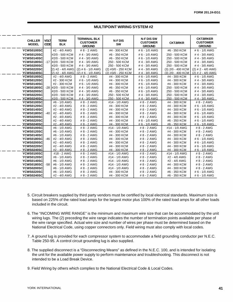
FORM 201.24-EG1
41YORK INTERNATIONAL
MULTIPOINT WIRING SYSTEM #2
YCWS0100SC #2 - 4/0 AWG # 8 - 2 AWG #4 - 300 KCM # 6 - 1/0 AWG #6 - 350 KCM # 6 - 1/0 AWGYCWS0120SC #2/0 - 500 KCM # 4 - 3/0 AWG #6 - 350 KCM # 6 - 1/0 AWG 250 - 500 KCM # 4 - 3/0 AWGYCWS0140SC #2/0 - 500 KCM # 4 - 3/0 AWG #6 - 350 KCM # 6 - 1/0 AWG 250 - 500 KCM # 4 - 3/0 AWGYCWS0180SC -17 #2/0 - 500 KCM # 4 - 3/0 AWG 250 - 500 KCM # 4 - 3/0 AWG 250 - 500 KCM # 4 - 3/0 AWGYCWS0200SC #2/0 - 500 KCM # 4 - 3/0 AWG 250 - 500 KCM # 4 - 3/0 AWG 250 - 500 KCM # 4 - 3/0 AWGYCWS0220SC (2) #2 - 4/0 AWG (2) # 6 - 1/0 AWG (2) #3/0 - 250 KCM # 4 - 3/0 AWG (3) 2/0 - 400 KCM (2) # 2 - 4/0 AWGYCWS0240SC (2) #2 - 4/0 AWG (2) # 6 - 1/0 AWG (2) #3/0 - 250 KCM # 4 - 3/0 AWG (3) 2/0 - 400 KCM (2) # 2 - 4/0 AWGYCWS0100SC #2 - 4/0 AWG # 8 - 2 AWG #4 - 300 KCM # 6 - 1/0 AWG #4 - 300 KCM # 6 - 1/0 AWGYCWS0120SC #2 - 300 KCM # 6 - 1/0 AWG #4 - 300 KCM # 6 - 1/0 AWG #4 - 300 KCM # 4 - 3/0 AWGYCWS0140SC #2 - 300 KCM # 6 - 1/0 AWG #4 - 300 KCM # 6 - 1/0 AWG #4 - 300 KCM # 4 - 3/0 AWGYCWS0180SC -28 #2/0 - 500 KCM # 4 - 3/0 AWG #6 - 350 KCM # 6 - 1/0 AWG 250 - 500 KCM # 4 - 3/0 AWGYCWS0200SC #2/0 - 500 KCM # 4 - 3/0 AWG #6 - 350 KCM # 6 - 1/0 AWG 250 - 500 KCM # 4 - 3/0 AWGYCWS0220SC #2/0 - 500 KCM # 4 - 3/0 AWG 250 - 500 KCM # 4 - 3/0 AWG 250 - 500 KCM # 4 - 3/0 AWGYCWS0240SC #2/0 - 500 KCM # 4 - 3/0 AWG 250 - 500 KCM # 4 - 3/0 AWG 250 - 500 KCM # 4 - 3/0 AWGYCWS0100SC #6 - 1/0 AWG # 8 - 2 AWG #14 - 1/0 AWG # 8 - 2 AWG #4 - 300 KCM # 8 - 2 AWGYCWS0120SC #2 - 4/0 AWG # 8 - 2 AWG #4 - 300 KCM # 8 - 2 AWG #4 - 300 KCM # 6 - 1/0 AWGYCWS0140SC #2 - 4/0 AWG # 8 - 2 AWG #4 - 300 KCM # 8 - 2 AWG #4 - 300 KCM # 6 - 1/0 AWGYCWS0180SC -40 #2 - 4/0 AWG # 8 - 2 AWG #4 - 300 KCM # 8 - 2 AWG #4 - 300 KCM # 6 - 1/0 AWGYCWS0200SC #2 - 4/0 AWG # 8 - 2 AWG #4 - 300 KCM # 8 - 2 AWG #4 - 300 KCM # 6 - 1/0 AWGYCWS0220SC #2 - 4/0 AWG # 8 - 2 AWG #4 - 300 KCM # 6 - 1/0 AWG #6 - 350 KCM # 6 - 1/0 AWGYCWS0240SC #2 - 4/0 AWG # 8 - 2 AWG #4 - 300 KCM # 6 - 1/0 AWG #6 - 350 KCM # 6 - 1/0 AWGYCWS0100SC #6 - 1/0 AWG # 8 - 2 AWG #14 - 1/0 AWG # 8 - 2 AWG #14 - 1/0 AWG # 8 - 2 AWGYCWS0120SC #6 - 1/0 AWG # 8 - 2 AWG #4 - 300 KCM # 8 - 2 AWG #4 - 300 KCM # 8 - 2 AWGYCWS0140SC #6 - 1/0 AWG # 8 - 2 AWG #4 - 300 KCM # 8 - 2 AWG #4 - 300 KCM # 8 - 2 AWGYCWS0180SC -46 #2 - 4/0 AWG # 8 - 2 AWG #4 - 300 KCM # 8 - 2 AWG #4 - 300 KCM # 6 - 1/0 AWGYCWS0200SC #2 - 4/0 AWG # 8 - 2 AWG #4 - 300 KCM # 8 - 2 AWG #4 - 300 KCM # 6 - 1/0 AWGYCWS0220SC #2 - 4/0 AWG # 8 - 2 AWG #4 - 300 KCM # 8 - 2 AWG #4 - 300 KCM # 6 - 1/0 AWGYCWS0240SC #2 - 4/0 AWG # 8 - 2 AWG #4 - 300 KCM # 8 - 2 AWG #4 - 300 KCM # 6 - 1/0 AWGYCWS0100SC #18 - 2 AWG # 8 - 2 AWG #14 - 1/0 AWG # 8 - 2 AWG #14 - 1/0 AWG # 8 - 2 AWGYCWS0120SC #6 - 1/0 AWG # 8 - 2 AWG #14 - 1/0 AWG # 8 - 2 AWG #2 - 4/0 AWG # 8 - 2 AWGYCWS0140SC #6 - 1/0 AWG # 8 - 2 AWG #14 - 1/0 AWG # 8 - 2 AWG #2 - 4/0 AWG # 8 - 2 AWGYCWS0180SC -58 #6 - 1/0 AWG # 8 - 2 AWG #14 - 1/0 AWG # 8 - 2 AWG #4 - 300 KCM # 8 - 2 AWGYCWS0200SC #6 - 1/0 AWG # 8 - 2 AWG #14 - 1/0 AWG # 8 - 2 AWG #4 - 300 KCM # 8 - 2 AWGYCWS0220SC #6 - 1/0 AWG # 8 - 2 AWG #4 - 300 KCM # 8 - 2 AWG #6 - 350 KCM # 6 - 1/0 AWGYCWS0240SC #2 - 4/0 AWG # 8 - 2 AWG #4 - 300 KCM # 8 - 2 AWG #6 - 350 KCM # 6 - 1/0 AWG
CHILLERMODEL
VOLTCODE
TERMBLK
TERMINAL BLKCUSTOMER
GROUND
N-F DISSW
N-F DIS SWCUSTOMER
GROUNDCKT.BRKR
CKT.BRKERCUSTOMER
GROUND
5. Circuit breakers supplied by third party vendors must be certified by local electrical standards. Maximum size isbased on 225% of the rated load amps for the largest motor plus 100% of the rated load amps for all other loadsincluded in the circuit.
6. The “INCOMING WIRE RANGE” is the minimum and maximum wire size that can be accommodated by the unitwiring lugs. The (2) preceding the wire range indicates the number of termination points available per phase ofthe wire range specified. Actual wire size and number of wires per phase must be determined based on theNational Electrical Code, using copper connectors only. Field wiring must also comply with local codes.
7. A ground lug is provided for each compressor system to accommodate a field grounding conductor per N.E.C.Table 250-95. A control circuit grounding lug is also supplied.
8. The supplied disconnect is a “Disconnecting Means” as defined in the N.E.C. 100, and is intended for isolatingthe unit for the available power supply to perform maintenance and troubleshooting. This disconnect is notintended to be a Load Break Device.
9. Field Wiring by others which complies to the National Electrical Code & Local Codes.
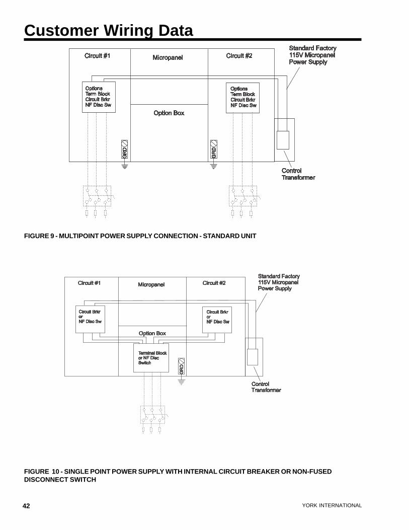
42 YORK INTERNATIONAL
FIGURE 9 - MULTIPOINT POWER SUPPLY CONNECTION - STANDARD UNIT
FIGURE 10 - SINGLE POINT POWER SUPPLY WITH INTERNAL CIRCUIT BREAKER OR NON-FUSEDDISCONNECT SWITCH
Customer Wiring Data
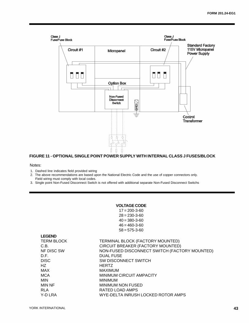
FORM 201.24-EG1
43YORK INTERNATIONAL
FIGURE 11 - OPTIONAL SINGLE POINT POWER SUPPLY WITH INTERNAL CLASS J FUSES/BLOCK
LEGENDTERM BLOCK TERMINAL BLOCK (FACTORY MOUNTED)C.B. CIRCUIT BREAKER (FACTORY MOUNTED)NF DISC SW NON-FUSED DISCONNECT SWITCH (FACTORY MOUNTED)D.F. DUAL FUSEDISC SW DISCONNECT SWITCHHZ HERTZMAX MAXIMUMMCA MINIMUM CIRCUIT AMPACITYMIN MINIMUMMIN NF MINIMUM NON FUSEDRLA RATED LOAD AMPSY-D LRA WYE-DELTA INRUSH LOCKED ROTOR AMPS
VOLTAGE CODE17 = 200-3-6028 = 230-3-6040 = 380-3-6046 = 460-3-6058 = 575-3-60
1. Dashed line indicates field provided wiring2. The above recommendations are based upon the National Electric Code and the use of copper connectors only. Field wiring must comply with local codes.3. Single point Non-Fused Disconnect Switch is not offered with additional separate Non-Fused Disconnect Switchs
Notes:
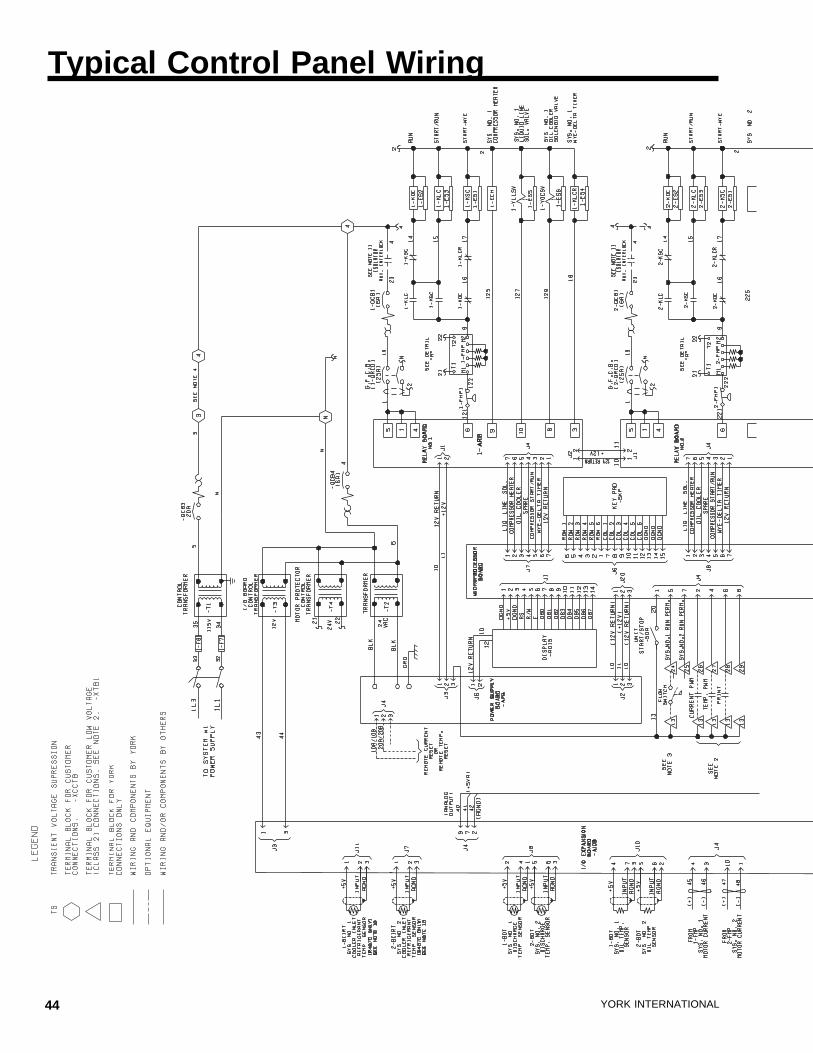
44 YORK INTERNATIONAL
Typical Control Panel Wiring
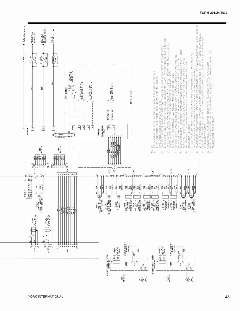
FORM 201.24-EG1
45YORK INTERNATIONAL
46 YORK INTERNATIONAL
UNIT LOCATIONChillers may be placed on the ground floor or upper floorof the building. The floor must be level and capable ofsupporting 150% of the operating weight of the unit. Unitsshould be located away from noise-critical areas. Ser-vice clearance must be allowed and include space forremoving cooler or condenser tubes. A doorway or win-dow can sometimes provide space for tube removal.Units should be installed indoors where they are not ex-posed to rain or water splash. Chillers should be locatednear a drain. The use of chillers in corrosive, dusty orexplosive atmospheres should be avoided unless theunit is properly protected. A unit located in a clean roomwill run best, require least maintenance, and last long-est. Heat or ventilation may be required to maintain theambient between 40°F and 115°F (4.4°C and 46.1°C).
UNIT ISOLATIONThe chiller foundation must be rigid to reduce vibrationtransmission to a minimum. All upper story installationsshould use vibration isolators under the unit base. Tomaintain isolator efficiency, no mechanical ties shouldbe made to the building. Properly selected flexible con-nectors and piping isolators are recommended. All theabove recommendations will help to reduce vibrationtransmission and result in a quieter operation.
FIELD CONNECTED WATER PIPINGPiping must comply in all respects with applicable localplumbing codes and ordinances. In no case should theunit support the weight of connecting piping. Since el-bows, tees, and valves increase pressure drop, all pip-ing should be kept as simple as possible. Hand stopvalves should be installed where required to facilitateservicing. Piping to the inlet and outlet connections ofthe cooler and condenser may include high-pressurerubber hose or piping loops to ensure against water pumptransmission of vibration.
Facilities should be provided for measuring temperatureand pressure in the cooler and condenser field waterpiping. Drain connections should be provided at all lowpoints to permit complete drainage of the cooler(s),condenser(s), and system piping. This is especially im-portant if the unit is located in an unheated room wherefreezing could prevail. Water lines subjected to ambienttemperatures below freezing may require heater cablesor antifreeze (by others).
Water loops should contain provisions for venting. Astrainer, preferably 40 mesh, should be installed in thecooler and condenser inlet lines, and located where itwill protect the circulating pump and the heat exchangertube bundles. It should be determined that the maximumwater pressure at the cooler or condenser does not ex-
ceed the maximum design working pressure of the cooleror condenser.
The water circulating pumps should be located on theinlet side of the heat exchangers. If, however, space doesnot permit this, the pumps may be located in the outletwater piping. The net positive suction head must be con-sidered when applying pumps.
PARALLEL CHILLER APPLICATIONMultiple chillers are often used to provide increased reli-ability, reserve capacity, or to divide the design capac-ity. The standard factory packaged chiller is most com-patible with parallel chilled liquid flow. Series flow arrange-ments are less desirable for pre-engineered packagedunits due to excessive chilled liquid flow rate and higherpressure drops. YORK recommends that standard pack-age chillers be arranged for parallel chilled liquid flow.
FIELD WIRINGAll field wiring must comply with the National ElectricCode and all applicable local codes. YORK liquid chillerunits are factory wired for optimum reliability. Thereforethe unit controls must not be modified without expressedwritten consent by YORK. The use of a simple switch ortimer from a remote point is permitted; but it must beconnected to the YORK unit panel at points expresslyindicated for that purpose.
Application Data
FORM 201.24-EG1
47YORK INTERNATIONAL
YORK Model YCWS ______ Packaged Chiller(s). The(each) unit shall have a cooling capacity of ______ tonswith Compressor kW when cooling GPM of water from______ °F (°C) to ______ °F (°C) and with ____ GPM ofcondensing water entering at ____ °F (°C) and leavingat _____ °F (°C), and a cooler fouling factor of _____and condenser water fouling factor of _____. The waterpressure drop shall not exceed ______ feet (kPa) ofwater through the cooler and ______ feet (kPa) of waterthrough the condenser. The unit overall dimensions shallnot exceed _____feet (mm) _____ ins. in length, ______feet (mm) _____ ins. in width and _____feet (mm) _____in height. The unit operating weight shall not exceed_____ lbs. (Kg).
GENERALThe (Each) Packaged Water Cooled Screw Chiller shallbe completely factory assembled (in an ISO 9001 regis-tered facility) including all interconnecting refrigerant pip-ing and internal wiring of controls, mounted on a steelbase which accommodates the condenser,compressor(s) and evaporator. Operating test shall in-clude operation with water flowing through the evapora-tor.
Unit shall be painted with Caribbean Blue enamel. Theunit shall be shipped with a full operating charge of R-22. The unit shall contain two separate refrigerant cir-cuits, each with a single compressor for standby opera-tion. All units shall be designed and constructed in ac-cordance with the applicable sections of the following:American Society of Heating, Refrigeration and Air Con-ditioning Engineers ANSI/ASHRAE 15 Safety Code forMechanical Refrigeration: American Society of Mechani-cal Engineers ASME Pressure Vessel Code; NationalElectrical Code/National Fire Protection AssociationNFPA 70. The unit shall be produced at an ISO 9001registered facility. All chillers are rated in accordancewith ARI Standard 550/590.
COMPRESSORSCompressors shall be direct drive, semi-hermetic, ro-tary twin-screw type, including: internal muffler, tempera-ture actuated ‚off-cycle heater, terminal box, internal dis-charge check, discharge and suction shutoff servicevalves, and precision machined cast iron housing. De-sign working pressure of entire compressor, suction todischarge, shall be 31 bar (450psig).
Motors shall feature refrigerant suction-gas cooled two-pole accessible hermetic compressor motor, full suctiongas flow through a mesh screen, with inherent internalthermal overload protection and external current over-load on all three phases. Motor stator shall employ
APT2000 type magnet wire.
Lubrication shall feature external oil separators with nomoving or fragile parts, 31 bar (450psig) design workingpressure, and UL listing. Refrigerant system differentialpressure shall provide oil flow through service replace-able, 0.5 micron, full flow, cartridge type oil filter internalto compressor. Filter bypass, less restrictive media, oroil pump not acceptable.
Compressors shall start at minimum load position. Ca-pacity control range from 100% to 10% of chiller full loadusing continuous function slide valves, and without hotgas bypass. Step unloading unacceptable. Provide Mi-croprocessor controlled, output pressure regulating ca-pacity control valve to command compressor capacityindependent of control valve input pressure and balancecompressor capacity with cooling load.
CAPACITY CONTROL SYSTEMContinuous function, microprocessor controlled, 3- wayproportional Capacity Control Valve provides regulatedoutput pressure independent of valve input pressure fora stable, smooth, and precise match of compressor ca-pacity to cooling load to 10% of chiller capacity.
COOLERThe cooler shall be a direct expansion shell and tubetype with refrigerant in the tubes and liquid to be chilledin the shell. The design working pressure of the coolershell (liquid) side shall be 150 PSIG for the tube (refrig-erant) side. Refrigerant heads shall be removable. Thecooler shall be covered with 3/4" flexible closed cell foaminsulation (K = 0.25 maximum) to prevent sweating. Thecooler shall be constructed and tested in accordancewith ASME Code requirements. Vent and drain connec-tions shall be included. The water connections shall befully accessible and grooved to accept victaulic couplingsif used (by others).
CONDENSERThe condenser is a cleanable thru-tube with steel shell,copper tubes, removable water heads and includes in-tegral subcooling. Refer to PHYSICAL DATA for designworking pressures. The shell will be constructed andtested in accordance with section VlII, division 1 of ASMEpressure-vessel code. The condenser is equipped withrelief valves and will hold the full refrigerant charge forpumpdown.
REFRIGERANT CIRCUITSTwo independent refrigerant circuits will be furnished on
Guide Specifications
48 YORK INTERNATIONAL
each unit. All piping will be ACR copper with brazed joints.The liquid line will include: a shutoff valve with chargingport; sightglass with moisture indicator; thermal expan-sion valve; solenoid valve; and high-absorption remov-able-core filter drier. The entire suction line and the liq-uid line between the expansion valve and the cooler willbe insulated with flexible, closed-cell, foam insulation.
MICROCOMPUTER CONTROL CENTEREach unit shall contain a Microcomputer Control Center.All logic and controls shall be contained within a IP 32(NEMA 1) cabinet with hinged outer door with positiveacting latches. Inside shall be contained the “userfriendly” and interactive inputs and outputs as follows:LCD display with light emitting diode back lighting foreasy viewing of data and input buttons for DISPLAY (tem-peratures, pressure, etc.). ENTRY (enter/cancel inputs,advance day, change AM/PM), SETPOINTS (change),CLOCK (set time and schedule), PRINT (calling up op-erating and shutdown data), PROGRAM (change inputsfrom special conditions such as brine chilling) and UNITON/OFF.
The Microcomputer Control Center shall be capable ofdisplaying the following: return and leaving liquid tem-perature; return and leaving condenser water tempera-ture (optional); low leaving liquid temperature cutout set-ting; system 1 and 2 percent full-load motor current andsuction, discharge (optional) and oil differential pressures;liquid pulldown control range (selectable for 0.6°C to 1.1°C [1°F to 2°F] in one-tenth increments above the set-point); liquid pull-down rate sensitivity (0.3°C to 3.0°C[0.5°F to 5°F]/minute in 0.05°C [0.1°F] increments); anti-
recycle timer status; compressor run status; no coolingload condition; day; date; time; out of range message;daily and holiday scheduling of start/stop times; auto-matic or manual lead/lag status; lead compressor defini-tion; number of compressor starts and running hours;status of hot gas bypass valves (option), liquid line sole-noid valves, and water pump; last three fault shutdownsdata; number of unloading steps; compressor load andunload timer status.
The operating program shall be stored in nonvolatilememory (EPROM) to eliminate chiller failure due to ACpower failure/battery discharge. Programmed setpointsare retained in lithium battery – backed RTC memory for5 years minimum.
Provisions shall be included for: pumpdown at shutdownand recycling pumpdown; a hard copy printout from aprinter (by others) via an RS-232 electrical output; twosteps of demand load limiting and remote chilled liquidreset from an external building automation system; unitalarm contacts; chilled water pump or remote air-cooledcondenser control; or Remote Control with printout ca-pability (up to 2000 feet) via an RS-485 electrical output.
POWER PANELThe power panel shall contain the compressor powerterminals. U.L. recognized compressor motor startingcontactors which meet l.E.C. requirements, current trans-former sensing for each compressor power source, forprotection against under current, over current, imbal-anced current, single phasing compressor stall andvoltage spikes.
Guide Specifications - Cont.

FORM 201.24-EG1
49YORK INTERNATIONAL

50 YORK INTERNATIONAL

FORM 201.24-EG1
51YORK INTERNATIONAL

Form 201.24-EG1 (701)New Release
RPC 3M 701 4.16Codes: DXS, ET


![APT2000 Series 2-Wire pH Transmitters User Manual€¦ · Fig. 1 Assembling the case ... and nut. 11 12. Assembly 7 32 [1.26] 80 [3.15] ... Terminal Assignment + meas. el. 14 8 7](https://img.pdfslide.net/doc/110x75/5b1fbce67f8b9a112c8b52db/apt2000-series-2-wire-ph-transmitters-user-fig-1-assembling-the-case-and.jpg)