Embed Size (px)
Citation preview
Form Deck - AVersatile Family
of Products
Richard B. Heagler
Author
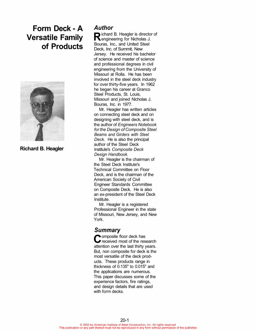
R ichard B. Heagler is director ofengineering for Nicholas J.
Bouras, Inc., and United SteelDeck, Inc. of Summit, NewJersey. He received his bachelorof science and master of scienceand professional degrees in civilengineering from the University ofMissouri at Rolla. He has beeninvolved in the steel deck industryfor over thirty-five years. In 1962he began his career at GrancoSteel Products, St. Louis,Missouri and joined Nicholas J.Bouras, Inc. in 1977.
Mr. Heagler has written articleson connecting steel deck and ondesigning with steel deck, and isthe author of Engineers Notebookfor the Design of Composite SteelBeams and Girders with SteelDeck. He is also the principalauthor of the Steel DeckInstitute's Composite DeckDesign Handbook.
Mr. Heagler is the chairman ofthe Steel Deck Institute'sTechnical Committee on FloorDeck, and is the chairman of theAmerican Society of CivilEngineer Standards Committeeon Composite Deck. He is alsoan ex-president of the Steel DeckInstitute.
Mr. Heagler is a registeredProfessional Engineer in the stateof Missouri, New Jersey, and NewYork.
Summary
Composite floor deck hasreceived most of the research
attention over the last thirty years.But, non composite for deck is themost versatile of the deck prod-ucts. These products range inthickness of 0.135" to 0.015" andthe applications are numerous.This paper discusses some of theexperience factors, fire ratings,and design details that are usedwith form decks.
20-1© 2003 by American Institute of Steel Construction, Inc. All rights reserved.
This publication or any part thereof must not be reproduced in any form without permission of the publisher.
STEEL FORM DECK
INTRODUCTION
Composite deck is the product that has attracted the most attention and certainly the mostresearch during the last thirty years. However, before there was composite deck there wasnon composite "form deck" which still enjoys a part of the market. "Form deck" might beconsidered a misnomer because the material is used in many ways besides being a stay inplace form for concrete. The purpose of this paper is to discuss the usual "form" use as wellas other functions and present some of the engineering and "experience" that influences thedesign.
Because this deck type can be used in such a variety of ways it has not had the same designor profile constraints that have influenced the shapes of the two other conventional products -roof deck and composite deck. Indeed, almost any deck, including floor deck and roof deck,can be considered to be "form deck" simply depending on its use. Figure 1 shows form deckprofiles regularly produced by United Steel Deck, Inc. and Figure 2 shows some of thecustom profiles that have been produced to satisfy a particular job needed. The gages rangefrom 10 (0.135 in., 3.4 mm) to 28 (0.0149 in., 0.38 mm) and the depths range from 9/16 in.(14 mm) to 7.6 in. (193 mm). This great variety of types illustrates that the product covers awide range of uses. The steel grades also cover a wide range - specified yield points rangefrom 33 to 80 ksi.
20-3© 2003 by American Institute of Steel Construction, Inc. All rights reserved.
This publication or any part thereof must not be reproduced in any form without permission of the publisher.
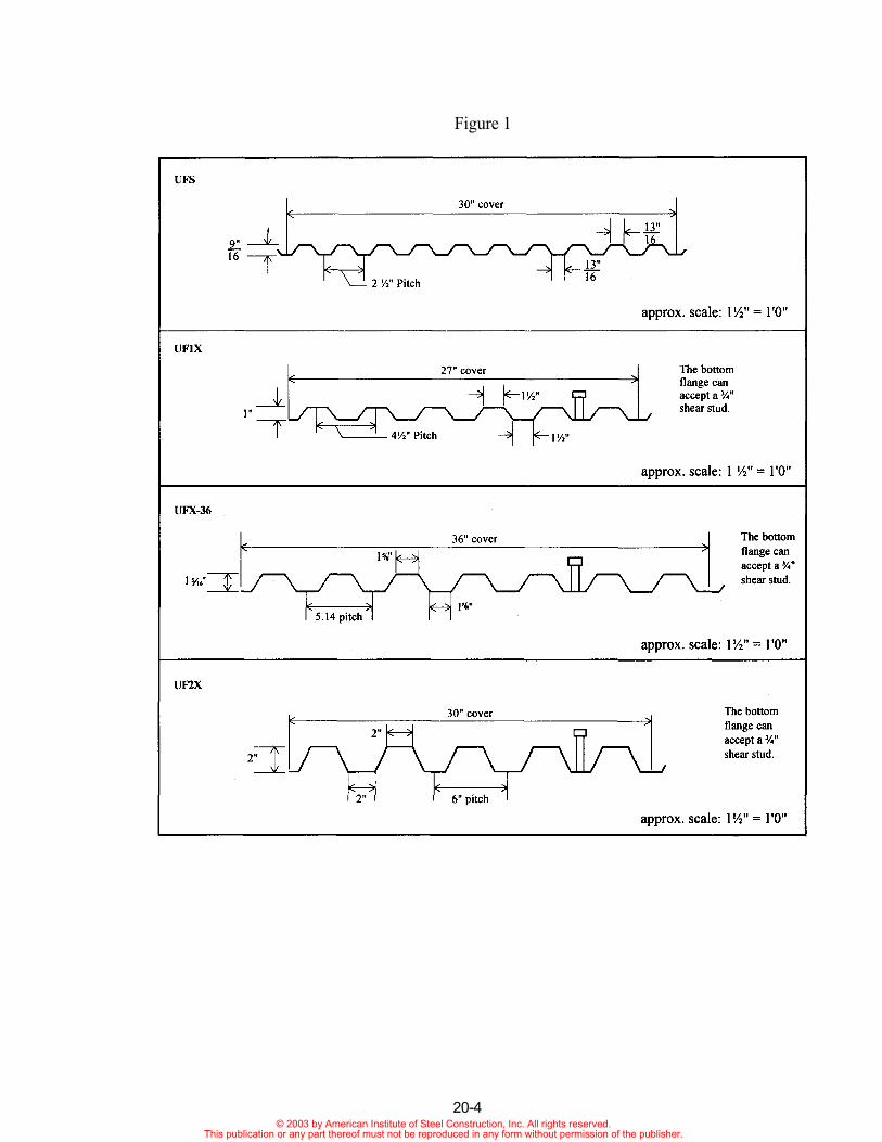
Figure 1
20-4© 2003 by American Institute of Steel Construction, Inc. All rights reserved.
This publication or any part thereof must not be reproduced in any form without permission of the publisher.
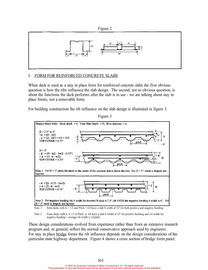
Figure 2
I. FORM FOR REINFORCED CONCRETE SLABS
When deck is used as a stay in place form for reinforced concrete slabs the first obviousquestion is how the ribs influence the slab design. The second, not so obvious question, isabout the functions the deck performs after the slab is in use - we are talking about stay inplace forms, not a removable form.
For building construction the rib influence on the slab design is illustrated in figure 3.
Figure 3
Note 1 Form decks with h < 1.5 and Pitch < 6.0 have a slab b width of 12" for both positive and negative bending.
Note 2. Form decks with h 1.5 or Pitch 6.0 have a slab b width of 12" for positive bending and a b width fornegative bending = average rib width x 12/pitch.
These design considerations evolved from experience rather than from an extensive researchprogram and, in general, reflect the normal conservative approach used by engineers.For stay in place bridge forms the rib influence depends on the design considerations of theparticular state highway department. Figure 4 shows a cross section of bridge form panel.
20-5© 2003 by American Institute of Steel Construction, Inc. All rights reserved.
This publication or any part thereof must not be reproduced in any form without permission of the publisher.
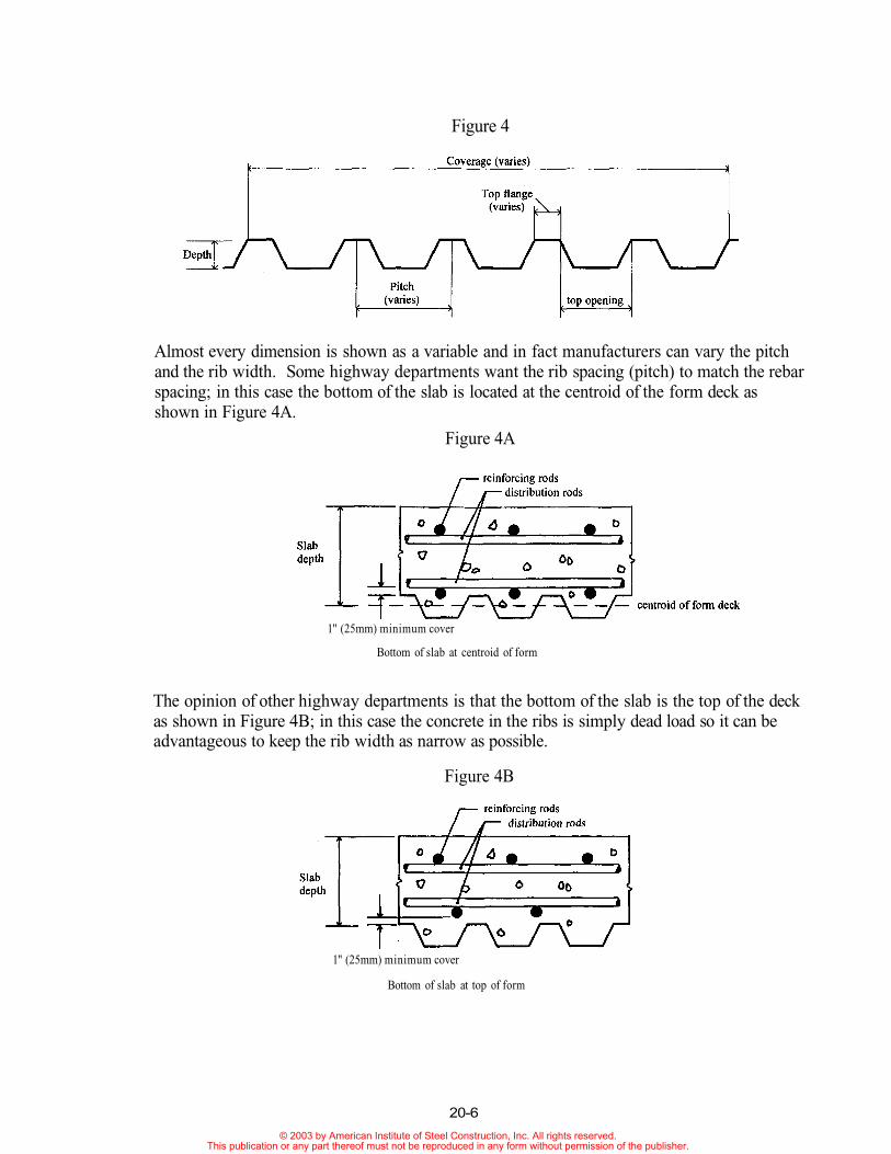
Figure 4
Almost every dimension is shown as a variable and in fact manufacturers can vary the pitchand the rib width. Some highway departments want the rib spacing (pitch) to match the rebarspacing; in this case the bottom of the slab is located at the centroid of the form deck asshown in Figure 4A.
Figure 4A
The opinion of other highway departments is that the bottom of the slab is the top of the deckas shown in Figure 4B; in this case the concrete in the ribs is simply dead load so it can beadvantageous to keep the rib width as narrow as possible.
Figure 4B
1" (25mm) minimum cover
Bottom of slab at centroid of form
1" (25mm) minimum cover
Bottom of slab at top of form
20-6
© 2003 by American Institute of Steel Construction, Inc. All rights reserved.This publication or any part thereof must not be reproduced in any form without permission of the publisher.
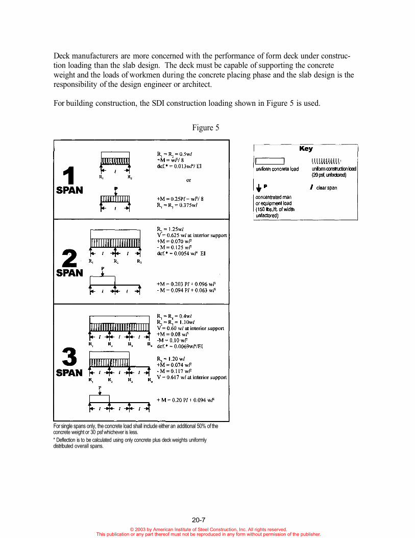
Deck manufacturers are more concerned with the performance of form deck under construc-tion loading than the slab design. The deck must be capable of supporting the concreteweight and the loads of workmen during the concrete placing phase and the slab design is theresponsibility of the design engineer or architect.
For building construction, the SDI construction loading shown in Figure 5 is used.
Figure 5
For single spans only, the concrete load shall include either an additional 50% of theconcrete weight or 30 psf whichever is less.* Deflection is to be calculated using only concrete plus deck weights uniformlydistributed overall spans.
20-7© 2003 by American Institute of Steel Construction, Inc. All rights reserved.
This publication or any part thereof must not be reproduced in any form without permission of the publisher.
This is the same loading used for composite floor deck. The loading formulas are used tocalculate the maximum allowable unshored spans; most slab construction is done without theuse of intermediate shores. If there are construction loading conditions different than thoseshown in Figure 5 then the engineer should either calculate the spans (or effects) based on theloading or contact the deck manufacturer to assist in the calculations.
Bridge form is a special application of form deck. If the use of the form deck is on a high-way bridge the construction loading is generally controlled by the State Department ofTransportation Specifications. If the bridge is not a highway bridge, but is for private use,then the designer is free to use the form deck loading recommended by the Steel Deck Insti-tute for building construction. The following information is for public highway bridgesdesigned by state D.O.T.'s.
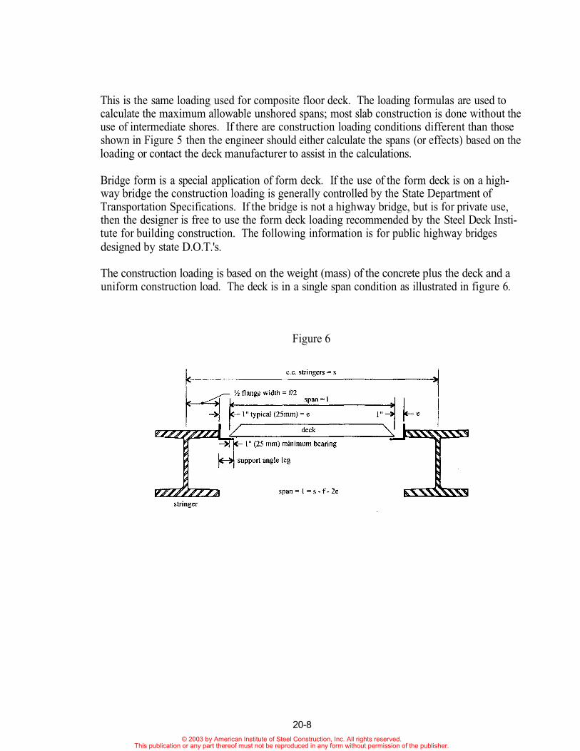
The construction loading is based on the weight (mass) of the concrete plus the deck and auniform construction load. The deck is in a single span condition as illustrated in figure 6.
Figure 6
20-8© 2003 by American Institute of Steel Construction, Inc. All rights reserved.
This publication or any part thereof must not be reproduced in any form without permission of the publisher.
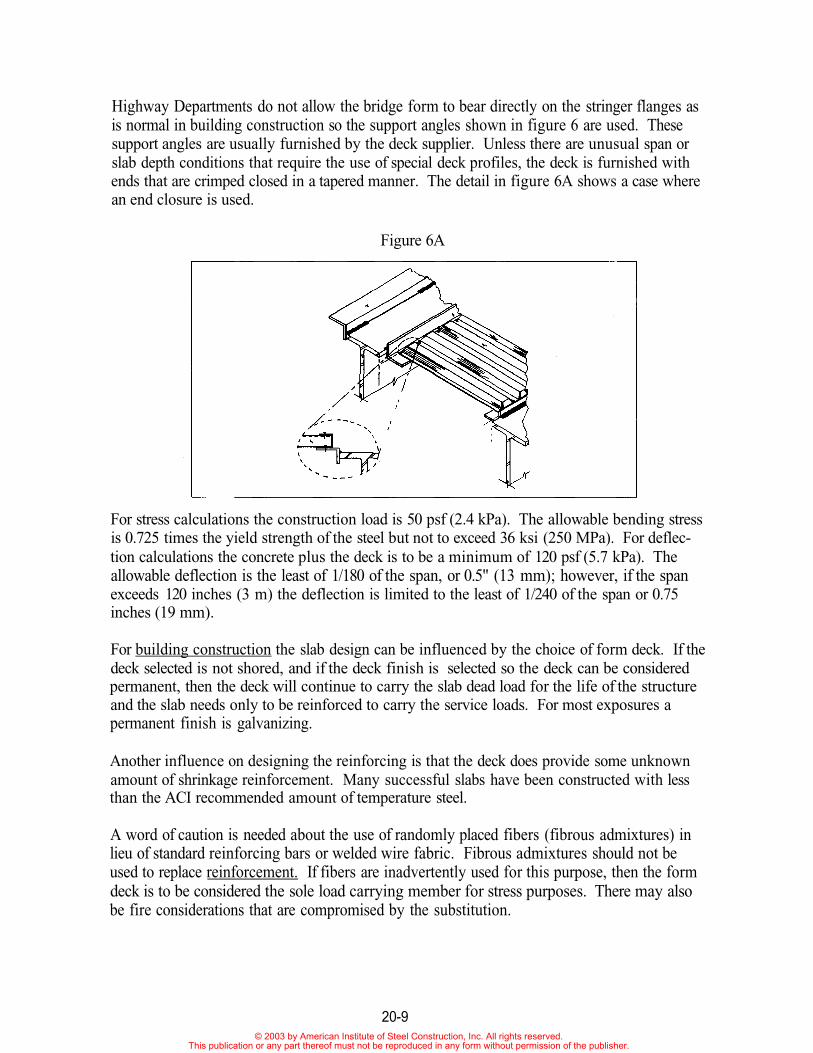
Highway Departments do not allow the bridge form to bear directly on the stringer flanges asis normal in building construction so the support angles shown in figure 6 are used. Thesesupport angles are usually furnished by the deck supplier. Unless there are unusual span orslab depth conditions that require the use of special deck profiles, the deck is furnished withends that are crimped closed in a tapered manner. The detail in figure 6A shows a case wherean end closure is used.
Figure 6A
For stress calculations the construction load is 50 psf (2.4 kPa). The allowable bending stressis 0.725 times the yield strength of the steel but not to exceed 36 ksi (250 MPa). For deflec-tion calculations the concrete plus the deck is to be a minimum of 120 psf (5.7 kPa). Theallowable deflection is the least of 1/180 of the span, or 0.5" (13 mm); however, if the spanexceeds 120 inches (3 m) the deflection is limited to the least of 1/240 of the span or 0.75inches (19 mm).
For building construction the slab design can be influenced by the choice of form deck. If thedeck selected is not shored, and if the deck finish is selected so the deck can be consideredpermanent, then the deck will continue to carry the slab dead load for the life of the structureand the slab needs only to be reinforced to carry the service loads. For most exposures apermanent finish is galvanizing.
Another influence on designing the reinforcing is that the deck does provide some unknownamount of shrinkage reinforcement. Many successful slabs have been constructed with lessthan the ACI recommended amount of temperature steel.
A word of caution is needed about the use of randomly placed fibers (fibrous admixtures) inlieu of standard reinforcing bars or welded wire fabric. Fibrous admixtures should not beused to replace reinforcement. If fibers are inadvertently used for this purpose, then the formdeck is to be considered the sole load carrying member for stress purposes. There may alsobe fire considerations that are compromised by the substitution.
20-9© 2003 by American Institute of Steel Construction, Inc. All rights reserved.
This publication or any part thereof must not be reproduced in any form without permission of the publisher.
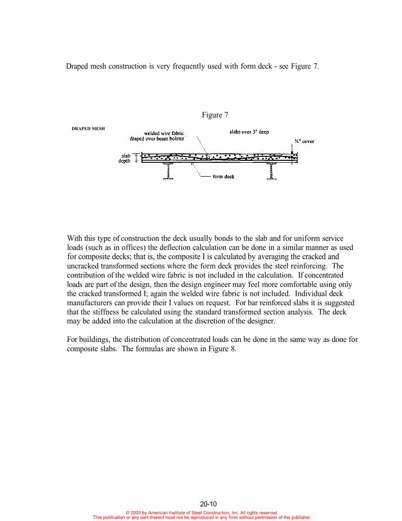
Draped mesh construction is very frequently used with form deck - see Figure 7.
Figure 7
DRAPED MESH
With this type of construction the deck usually bonds to the slab and for uniform serviceloads (such as in offices) the deflection calculation can be done in a similar manner as usedfor composite decks; that is, the composite I is calculated by averaging the cracked anduncracked transformed sections where the form deck provides the steel reinforcing. Thecontribution of the welded wire fabric is not included in the calculation. If concentratedloads are part of the design, then the design engineer may feel more comfortable using onlythe cracked transformed I; again the welded wire fabric is not included. Individual deckmanufacturers can provide their I values on request. For bar reinforced slabs it is suggestedthat the stiffness be calculated using the standard transformed section analysis. The deckmay be added into the calculation at the discretion of the designer.
For buildings, the distribution of concentrated loads can be done in the same way as done forcomposite slabs. The formulas are shown in Figure 8.
20-10© 2003 by American Institute of Steel Construction, Inc. All rights reserved.
This publication or any part thereof must not be reproduced in any form without permission of the publisher.
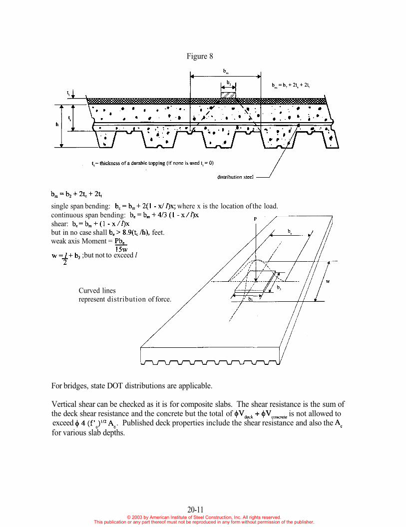
Figure 8
single span bending: where x is the location of the load.continuous span bending:shear:but in no case shall feet.weak axis Moment =
;but not to exceed l
Curved linesrepresent distribution of force.
For bridges, state DOT distributions are applicable.
Vertical shear can be checked as it is for composite slabs. The shear resistance is the sum ofthe deck shear resistance and the concrete but the total of is not allowed toexceed . Published deck properties include the shear resistance and also thefor various slab depths.
20-11© 2003 by American Institute of Steel Construction, Inc. All rights reserved.
This publication or any part thereof must not be reproduced in any form without permission of the publisher.
II. INSULATING FILLS ON FORM DECK
Lightweight insulating cementitious fill roof systems are supported by form deck. Thisconstruction may also include embedded rigid insulation boards within the poured fill mate-rial. In most cases the fill material has an "aggregate" of some insulating material such asvermiculite, expanded perlite, foamed glass, or simply be very highly air entrained where theair bubbles are the "aggregate". The fill material is generally not considered to add to thevertical load carrying capacity - the deck is selected to carry this load - but it does add to thestiffness and to the diaphragm strength. Individual fill manufacturers can provide load limitsbased on deflection and often can also provide diaphragm tables. The Steel Deck Institute(SDI) has diaphragm tables for the only generic form deck (2 ½" x ½") both with an withoutembedded boards. Not all fill material types are covered in the SDI tables.
In many cases the fill material contains a great deal of water. Some of this water is absorbedby aggregate materials and the fill stays rather damp. During the life of the roof system itwill be subject to many days of solar exposure and the heat can cause a vapor pressure todevelop within the fill. The form deck must be vented to relieve the pressure so that the roofmembrane is not distressed. When these fill systems were new in the market, the deck wasvented by either installing clips or rolling indentations into the side laps to create a ventingspace along each deck edge. Tests were done at Granco Steel Products Company to deter-mine the venting ability of deck with rolled in slits. These tests showed vents that providedbetween 1 and 1.5% of the projected area were sufficient to relieve the vapor pressure. How-ever more important than the actual area size was the distribution of the vents. Small welldistributed slits were better than widely spaced large openings.
Because of the great amount of water in the mix and because some of the insulative additiveshold water for a long time, and because the deck must carry the load for the life of the roof, agalvanized finish is required.
If insulation boards are embedded in the fill material it is recommended that the boards beheld away at least three feet from the edges, where the diaphragm shear transfers into theframe.
III. EXPOSED ROOFING
Form deck as exposed roofing runs a wide range of uses from temporary coverings to perma-nent architectural applications. The details of construction vary with the application. Forinstance if the use is to provide temporary cover over a walkway, then perhaps completesealing against leaks may not be too important and side laps may be done without any extraattention. If, on the other hand, the roof is to be a permanent cover then some thought shouldbe given to continuously caulking the seam; perhaps with a caulking tape. Slope also helpsto keep water out of joints and slopes 45° or greater do not generally require caulking. Atten-tion should also be given to the form deck orientation. Figure 9 shows the common B (widerib) roof deck used inverted as exposed roofing.
20-12© 2003 by American Institute of Steel Construction, Inc. All rights reserved.
This publication or any part thereof must not be reproduced in any form without permission of the publisher.
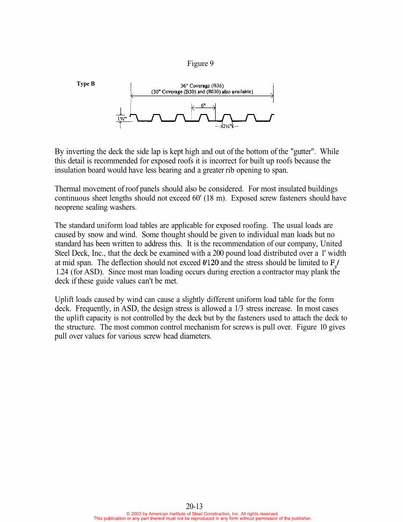
Figure 9
Type B
By inverting the deck the side lap is kept high and out of the bottom of the "gutter". Whilethis detail is recommended for exposed roofs it is incorrect for built up roofs because theinsulation board would have less bearing and a greater rib opening to span.
Thermal movement of roof panels should also be considered. For most insulated buildingscontinuous sheet lengths should not exceed 60' (18 m). Exposed screw fasteners should haveneoprene sealing washers.
The standard uniform load tables are applicable for exposed roofing. The usual loads arecaused by snow and wind. Some thought should be given to individual man loads but nostandard has been written to address this. It is the recommendation of our company, UnitedSteel Deck, Inc., that the deck be examined with a 200 pound load distributed over a 1' widthat mid span. The deflection should not exceed and the stress should be limited to1.24 (for ASD). Since most man loading occurs during erection a contractor may plank thedeck if these guide values can't be met.
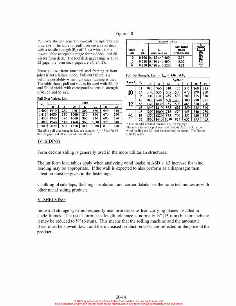
Uplift loads caused by wind can cause a slightly different uniform load table for the formdeck. Frequently, in ASD, the design stress is allowed a 1/3 stress increase. In most casesthe uplift capacity is not controlled by the deck but by the fasteners used to attach the deck tothe structure. The most common control mechanism for screws is pull over. Figure 10 givespull over values for various screw head diameters.
20-13© 2003 by American Institute of Steel Construction, Inc. All rights reserved.
This publication or any part thereof must not be reproduced in any form without permission of the publisher.
IV SIDING
Form deck as siding is generally used in the more utilitarian structures.
The uniform load tables apply when analyzing wind loads; in ASD a 1/3 increase for windloading may be appropriate. If the wall is expected to also perform as a diaphragm thenattention must be given to the fastenings.
Caulking of side laps, flashing, insulation, and corner details use the same techniques as withother metal siding products.
V SHELVING
Industrial storage systems frequently use form decks as load carrying planes installed inangle frames. The usual form deck length tolerance is normally ½" (13 mm) but for shelvingit may be reduced to ¼" (6 mm). This means that the rolling machine and the automaticshear must be slowed down and the increased production costs are reflected in the price of theproduct.
20-14
Pull over strength generally controls the uplift valuesof screws. The table for pull over covers roof deckwith a tensile strength of 45 ksi which is thelowest of the e range for roof deck, and 60ksi for form deck. The roof deck gage range is 16 to22 gage; the form deck gages are 24, 26, 28.
Screw pull out from structural steel framing or fromjoists is not a failure mode. Pull out failure is adefinite possibility when light gage framing is used.The table shows pull out values for steel with 33, 40and 50 ksi yields with corresponding tensile strengthof 45, 55 and 65 ksi.
Figure 10
* Use the SDI decimal thickness, t2, for the gage.The safety factor for pull over and pullout (ASD) is 3, but forwind loading the 1/3 load increase may be proper. The f factor(LRFD) is 0.5.
The table pull over strengths Lbs., are based on = 45 ksi for 16thru 22 gage, and 60 ksi for 24 thru 28 gage.
Pull Over Values, Lbs.
Pull Out Strength, Lbs. =
SCREW DATA
acceptabl
© 2003 by American Institute of Steel Construction, Inc. All rights reserved.This publication or any part thereof must not be reproduced in any form without permission of the publisher.
VI DRAFT CURTAINS (Curtain Boards)
Steel Form deck, because it is "non combustible" is frequently used in large open area build-ings as a smoke control curtain. These curtains are made by hanging the deck vertically fromprimary structural members. The lightest available deck is obviously the best choice.
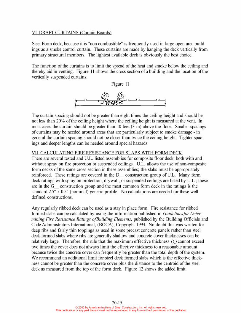
The function of the curtains is to limit the spread of the heat and smoke below the ceiling andthereby aid in venting. Figure 11 shows the cross section of a building and the location of thevertically suspended curtains.
Figure 11
The curtain spacing should not be greater than eight times the ceiling height and should benot less than 20% of the ceiling height where the ceiling height is measured at the vent. Inmost cases the curtain should be greater than 10 feet (3 m) above the floor. Smaller spacingsof curtains may be needed around areas that are particularly subject to smoke damage - ingeneral the curtain spacing should not be closer than twice the ceiling height. Tighter spac-ings and deeper lengths can be needed around special hazards.
VII CALCULATING FIRE RESISTANCE FOR SLABS WITH FORM DECKThere are several tested and U.L. listed assemblies for composite floor deck, both with andwithout spray on fire protection or suspended ceilings. U.L. allows the use of non-compositeform decks of the same cross section in these assemblies; the slabs must be appropriatelyreinforced. These ratings are covered in the D__ construction group of U.L. Many formdeck ratings with spray on protection, dry wall, or suspended ceilings are listed by U.L.; theseare in the G__ construction group and the most common form deck in the ratings is thestandard 2.5" x 0.5" (nominal) generic profile. No calculations are needed for these welldefined constructions.
Any regularly ribbed deck can be used as a stay in place form. Fire resistance for ribbedformed slabs can be calculated by using the information published in Guidelines for Deter-mining Fire Resistance Ratings of Building Elements, published by the Building Officials andCode Administrators International, (BOCA), Copyright 1994. No doubt this was written fordeep ribs and fairly thin toppings as used in some precast concrete panels rather than steeldeck formed slabs where ribs are generally shallow and concrete cover thicknesses can berelatively large. Therefore, the rule that the maximum effective thickness cannot exceedtwo times the cover does not always limit the effective thickness to a reasonable amountbecause twice the concrete cover can frequently be greater than the total depth of the system.We recommend an additional limit for steel deck formed slabs which is the effective thick-ness cannot be greater than the concrete cover plus the distance to the centroid of the steeldeck as measured from the top of the form deck. Figure 12 shows the added limit.
20-15© 2003 by American Institute of Steel Construction, Inc. All rights reserved.
This publication or any part thereof must not be reproduced in any form without permission of the publisher.
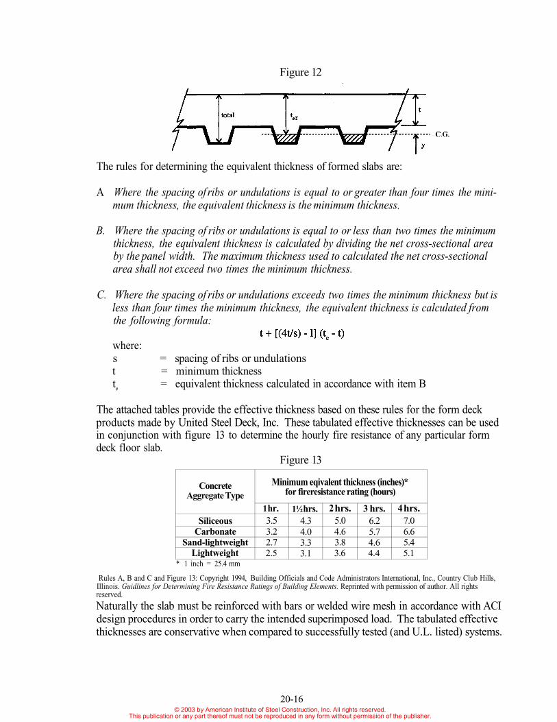
Figure 12
The rules for determining the equivalent thickness of formed slabs are:
A Where the spacing of ribs or undulations is equal to or greater than four times the mini-mum thickness, the equivalent thickness is the minimum thickness.
B. Where the spacing of ribs or undulations is equal to or less than two times the minimumthickness, the equivalent thickness is calculated by dividing the net cross-sectional areaby the panel width. The maximum thickness used to calculated the net cross-sectionalarea shall not exceed two times the minimum thickness.
C. Where the spacing of ribs or undulations exceeds two times the minimum thickness but isless than four times the minimum thickness, the equivalent thickness is calculated fromthe following formula:
where:s = spacing of ribs or undulationst = minimum thicknesste = equivalent thickness calculated in accordance with item B
The attached tables provide the effective thickness based on these rules for the form deckproducts made by United Steel Deck, Inc. These tabulated effective thicknesses can be usedin conjunction with figure 13 to determine the hourly fire resistance of any particular formdeck floor slab.
Figure 13
Naturally the slab must be reinforced with bars or welded wire mesh in accordance with ACIdesign procedures in order to carry the intended superimposed load. The tabulated effectivethicknesses are conservative when compared to successfully tested (and U.L. listed) systems.
Rules A, B and C and Figure 13: Copyright 1994, Building Officials and Code Administrators International, Inc., Country Club Hills,Illinois. Guidlines for Determining Fire Resistance Ratings of Building Elements. Reprinted with permission of author. All rightsreserved.
20-16
* 1 inch = 25.4 mm
ConcreteAggregate Type
SiliceousCarbonate
Sand-lightweightLightweight
Minimum eqivalent thickness (inches)*for fireresistance rating (hours)
1 hr.3.53.22.72.5
1½ hrs.4.34.03.33.1
2 hrs.5.04.63.83.6
3 hrs.6.25.74.64.4
4 hrs.7.06.65.45.1
© 2003 by American Institute of Steel Construction, Inc. All rights reserved.This publication or any part thereof must not be reproduced in any form without permission of the publisher.
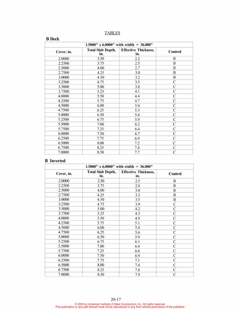
1.5000" x 6.0000" with width = 36.000"
Cover, in.
2.00002.25002.50002.75003.00003.25003.50003.75004.00004.25004.50004.75005.00005.25005.50005.75006.00006.25006.50006.75007.0000
Total Slab Depth,in.
3.503.754.004.254.504.755.005.255.505.756.006.256.506.757.007.257.507.758.008.258.50
Effective Thickness,in.2.22.52.73.03.23.53.84.14.44.75.05.35.65.96.26.46.76.97.27.47.7
Control
BBBBBCCCCCCCCCCCCCCCC
B DeckTABLES
B Inverted
20-17
1.5000" x 6.0000" with width = 36.000"
Cover, in.
2.00002.25002.50002.75003.00003.25003.50003.75004.00004.25004.50004.75005.00005.25005.50005.75006.00006.25006.50006.75007.0000
Total Slab Depth,in.
3.503.754.004.254.504.755.005.255.505.756.006.256.506.757.007.257.507.758.008.258.50
Effective Thickness,in.2.52.83.03.33.53.94.24.54.95.15.45.65.96.16.46.66.97.17.47.67.9
Control
BBBBBCCCCCCCCCCCCCCCC
© 2003 by American Institute of Steel Construction, Inc. All rights reserved.This publication or any part thereof must not be reproduced in any form without permission of the publisher.
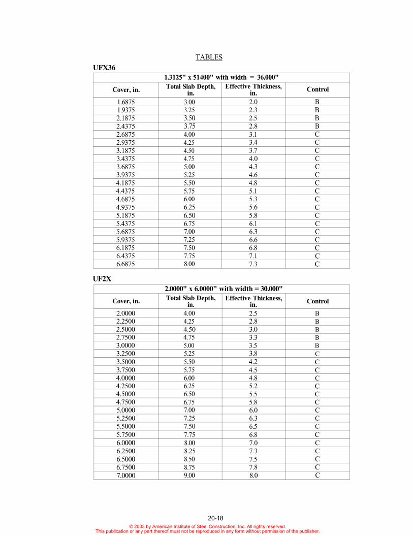
UFX36TABLES
1.3125" x 51400" with width = 36.000"
Cover, in.
1.68751.93752.18752.43752.68752.93753.18753.43753.68753.93754.18754.43754.68754.93755.18755.43755.68755.93756.18756.43756.6875
Total Slab Depth,in.
3.003.253.503.754.004.254.504.755.005.255.505.756.006.256.506.757.007.257.507.758.00
Effective Thickness,in.2.02.32.52.83.13.43.74.04.34.64.85.15.35.65.86.16.36.66.87.17.3
Control
BBBBCCCCCCCCCCCCCCCCC
2.0000" x 6.0000" with width = 30.000"
Cover, in.
2.00002.25002.50002.75003.00003.25003.50003.75004.00004.25004.50004.75005.00005.25005.50005.75006.00006.25006.50006.75007.0000
Total Slab Depth,in.
4.004.254.504.755.005.255.505.756.006.256.506.757.007.257.507.758.008.258.508.759.00
Effective Thickness,in.2.52.83.03.33.53.84.24.54.85.25.55.86.06.36.56.87.07.37.57.88.0
Control
BBBBBCCCCCCCCCCCCCCCC
UF2X
20-18© 2003 by American Institute of Steel Construction, Inc. All rights reserved.
This publication or any part thereof must not be reproduced in any form without permission of the publisher.
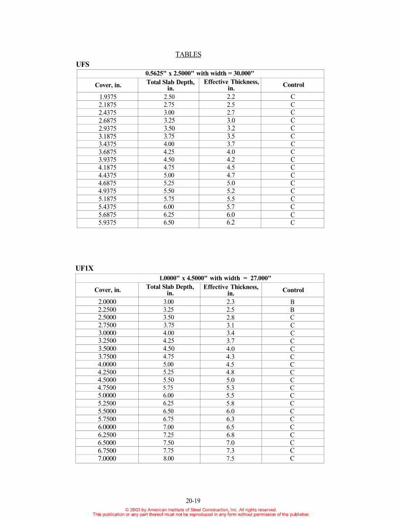
1.0000" x 4.5000" with width = 27.000"
Cover, in.
2.00002.25002.50002.75003.00003.25003.50003.75004.00004.25004.50004.75005.00005.25005.50005.75006.00006.25006.50006.75007.0000
Total Slab Depth,in.
3.003.253.503.754.004.254.504.755.005.255.505.756.006.256.506.757.007.257.507.758.00
Effective Thickness,in.2.32.52.83.13.43.74.04.34.54.85.05.35.55.86.06.36.56.87.07.37.5
Control
BBCCCCCCCCCCCCCCCCCCC
UF1X
UFSTABLES
0.5625" x 2.5000" with width = 30.000"
Cover, in.
1.93752.18752.43752.68752.93753.18753.43753.68753.93754.18754.43754.68754.93755.18755.43755.68755.9375
Total Slab Depth,in.
2.502.753.003.253.503.754.004.254.504.755.005.255.505.756.006.256.50
Effective Thickness,in.2.22.52.73.03.23.53.74.04.24.54.75.05.25.55.76.06.2
Control
CCCCCCCCCCCCCCCCC
20-19© 2003 by American Institute of Steel Construction, Inc. All rights reserved.
This publication or any part thereof must not be reproduced in any form without permission of the publisher.
REFERENCES
Heagler, R.B., Luttrell, L.D., and Easterling W.S. (1997) "Composite Deck DesignHandbook, Second Edition", SDI, Fox River Grove, IL.
Luttrell, C.B. (1995), "Transverse Distribution of Non Uniform Loads on Composite Slabs",West Virginia University, Morgantown, WV.
"Bridge Form", (1996), SDI, Elk River Grove, IL.
"Building Code Requirements for Reinforced Concrete", ACI 318-89, (1992), ACI, Detroit,MI.
"Fire Protection Handbook", (1997), NFPA, Quincy, MA.
"Fire Resistance Directory", (1997), Underwriters Laboratories, Northbrook, IL.
"Guidelines for Determining Fire Resistance Ratings of Building Elements", (1994), BOCAInternational, Country Club Hills, IL.
"Manual of Steel Construction (LRFD Second Edition, Volume 1)", 1994, AISC, Chicago,IL.
"Specification for the Design of Cold-Formed Steel Structural Members", (1996), AISI,Washington, DC.
"Steel Deck Institute Design Manual", (1995), SDI, Fox River Grove, IL.
"Steel Decks for Floors and Roofs", (1997), United Steel Deck, Inc., Summit, NJ.
20-20© 2003 by American Institute of Steel Construction, Inc. All rights reserved.
This publication or any part thereof must not be reproduced in any form without permission of the publisher.