Embed Size (px)
Citation preview

Visit us online to register your warrantywww.thermoscientific.com/labwarranty
User M
anual
Forma Environmental ChamberModel 3940 and 3911 SeriesOperating and Maintenance Manual 7053940 Rev. 19
Thermo Scientific
MANUAL NUMBER 7053940
19 41345 5/02/17 Added F-gas statement bpg
18 40398 / 41195 4/20/17 Updated 3940, 3949 electrical schematic, removed fuse label bpg
17 41276/IN-4783 12/13/16 Updated 3949 electrical schematic, t-stat 403942 ccs
16 40639 5/3/16 Added risk assessment info ccs
15 40356/40509/ 2/7/15 Updates to fuses, accessory outlet, electrical schematics ccs
40638/IN-4670
14 40509/IN-4695 10/5/15 Added Safety Specifications - pg 5-3 ccs
13 40190 9/24/15 Updated electrical schematics with TMOV to float switch ccs
12 30076 8/5/15 Added cabinet tuning information, updated Humidity configuration records ccs
-- 29639 8/5/15 Added note for heatless dryer calibration to pgs 1-12 and 2-5 ccs
11 40018 2/9/15 Added drain figure on pg 1-3 ccs
Preface
Model 3900 Series i
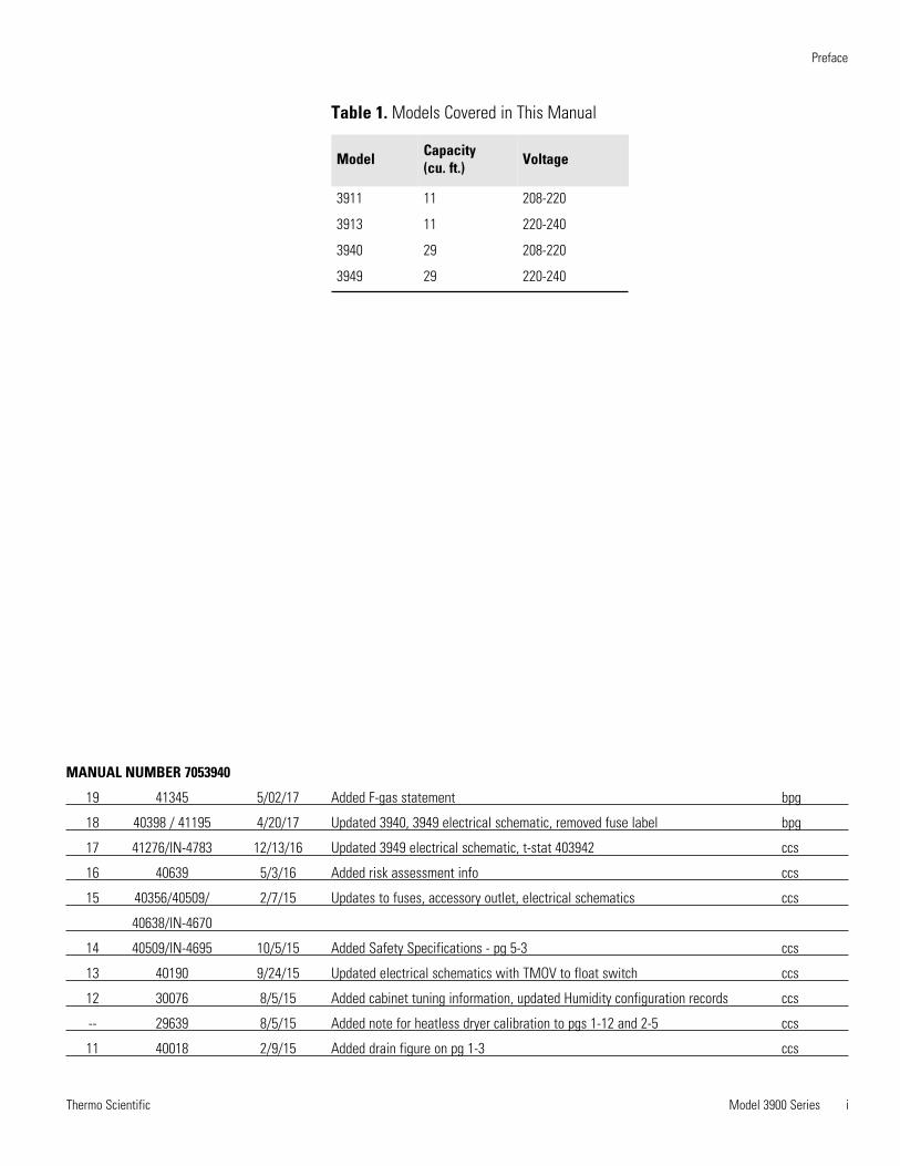
Model Capacity (cu. ft.) Voltage
3911 11 208-220
3913 11 220-240
3940 29 208-220
3949 29 220-240
Table 1. Models Covered in This Manual
Thermo Scientificii Model 3900 Series
Preface
Contains Parts and Assemblies
Susceptible to Damage by
Electrostatic Discharge (ESD)
CAUTION
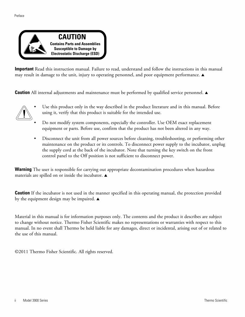
Important Read this instruction manual. Failure to read, understand and follow the instructions in this manualmay result in damage to the unit, injury to operating personnel, and poor equipment performance. s
Caution All internal adjustments and maintenance must be performed by qualified service personnel. s
• Use this product only in the way described in the product literature and in this manual. Beforeusing it, verify that this product is suitable for the intended use.
• Do not modify system components, especially the controller. Use OEM exact replacementequipment or parts. Before use, confirm that the product has not been altered in any way.
• Disconnect the unit from all power sources before cleaning, troubleshooting, or performing othermaintenance on the product or its controls. To disconnect power supply to the incubator, unplugthe supply cord at the back of the incubator. Note that turning the key switch on the frontcontrol panel to the Off position is not sufficient to disconnect power.
Warning The user is responsible for carrying out appropriate decontamination procedures when hazardousmaterials are spilled on or inside the incubator. s
Caution If the incubator is not used in the manner specified in this operating manual, the protection providedby the equipment design may be impaired. s
Material in this manual is for information purposes only. The contents and the product it describes are subjectto change without notice. Thermo Fisher Scientific makes no representations or warranties with respect to thismanual. In no event shall Thermo be held liable for any damages, direct or incidental, arising out of or related tothe use of this manual.
©2011 Thermo Fisher Scientific. All rights reserved.

Thermo Scientific Model 3900 Series iii
Preface
Important operating and/or maintenance instructions. Read the accompanying text carefully.
Potential electrical hazards. Only qualified persons should perform procedures associated with thissymbol.
Equipment being maintained or serviced must be turned off and locked off to prevent possible injury.
Asphyxiation Hazard Warning. High concentrations of CO2 and N2 can displace oxygen and causeasphyxiation!
Lifting Hazard Warning. The incubator weighs more than 200lbs (91kgs). Take adequate safetymeasures when moving this device.
WEEE Compliance: Thermo Fisher Scientific has contracted with companies for recycling/disposal ineach EU Member State. For further information, send an email to [email protected].
4 Always use the proper protective equipment (clothing, gloves, goggles, etc.)
4 Always dissipate extreme cold or heat and wear protective clothing.
4 Always follow good hygiene practices.
4 Each individual is responsible for his or her own safety.

Thermo Scientificiv Model 3900 Series
Preface
Do You Need Information or Assistance on
Thermo Scientific Products?
If you do, please contact us 8:00 a.m. to 6:00 p.m. (Eastern Time) at:
1-740-373-4763 Direct
1-800-438-4851 Toll Free, U.S. and Canada
1-877-213-8051 FAX
http://www.thermofisher.com Internet Worldwide Web Home Page
[email protected] Tech Support Email Address
Certified Service Web Pagewww.unitylabservices.com
Our staff can provide information on pricing and give you quotations. We canSales Support
take your order and provide delivery information on major equipment items or make
arrangements to have your local sales representative contact you. Our products are listed on the
Internet and we can be contacted through our Internet home page.
Our staff can supply technical information about proper setup, operation orService Support
troubleshooting of your equipment. We can fill your needs for spare or replacement parts or
provide you with on-site service. We can also provide you with a quotation on our Extended
Warranty for your Thermo Scientific products.
Whatever Thermo Scientific products you need or use, we will be happy to discuss your
applications. If you are experiencing technical problems, working together, we will help you
locate the problem and, chances are, correct it yourself...over the telephone without a service
call.
When more extensive service is necessary, we will assist you with direct factory trained
technicians or a qualified service organization for on-the-spot repair. If your service need is
covered by the warranty, we will arrange for the unit to be repaired at our expense and to your
satisfaction.
Regardless of your needs, our professional telephone technicians are available to assist you
Monday through Friday from 8:00 a.m. to 6:00 p.m. Eastern Time. Please contact us by
telephone or fax. If you wish to write, our mailing address is:
Thermo Fisher Scientific (Asheville) LLC
401 Millcreek Road, Box 649
Marietta, OH 45750
International customers, please contact your local Thermo Scientific distributor.

Thermo Scientific Model 3900 Series v
Preface
Warranty Notes
Information You Should Know Before Requesting Warranty Service
• Locate the model and serial numbers. A serial tag is located on the unit itself.
• For equipment service or maintenance, or with technical or special application inquiries, contact TechnicalServices at 1-800-438-4851 or 1-740-373-4763 (USA and Canada). Outside the USA, contact your local distributor.
Repairs NOT Covered Under Warranty
• Calibration of control parameters. Nominal calibrations are performed at the factory; typically ±1°C fortemperature, ±1% for gases, and ±5% for humidity. Our service personnel can provide precise calibrations asa billable service at your location. Calibration after a warranty repair is covered under the warranty.
• Damage resulting from use of improper quality water, chemicals or cleaning agents detrimental toequipment materials.
• Service calls for improper installation or operating instructions. Corrections to any of the following are billable services:
1) electrical service connection
2) tubing connections
3) gas regulators
4) gas tanks
5) unit leveling
6) room ventilation
7) adverse ambient temperature fluctuations
8) any repair external to the unit
• Damage resulting from accident, alteration, misuse, abuse, fire, flood, acts of God, or improperinstallation.
• Repairs to parts or systems resulting from unauthorized unit modifications.
• Any labor costs other than that specified during the parts and labor warranty period, which mayinclude additional warranty on CO2 sensors, blower motors, water jackets, etc.
Model 3900 Series viThermo Scientific
Table of Contents
Installation and Set-Up . . . . . . . . . . . . . . . . . . . . . . . . . . . . . . . . . . . . . . . 1-1Preliminary Cleaning and Disinfecting . . . . . . . . . . . . . . . . . . . . . . . 1-1Installing the Shelves . . . . . . . . . . . . . . . . . . . . . . . . . . . . . . . . . . . . . 1-1Leveling the Unit . . . . . . . . . . . . . . . . . . . . . . . . . . . . . . . . . . . . . . . . 1-1Installing the Wall Anchors . . . . . . . . . . . . . . . . . . . . . . . . . . . . . . . . 1-2Connect Water Inlet for Humidity System . . . . . . . . . . . . . . . . . . . . 1-2Alternate Water Supply for Humidity System . . . . . . . . . . . . . . . . .1-3
Connect Drain Line . . . . . . . . . . . . . . . . . . . . . . . . . . . . . . . . . . . . . .1-34-20 Milliamp Output . . . . . . . . . . . . . . . . . . . . . . . . . . . . . . . . . . . 1-4Remote Alarm Contacts . . . . . . . . . . . . . . . . . . . . . . . . . . . . . . . . . . .1-4Power Connection . . . . . . . . . . . . . . . . . . . . . . . . . . . . . . . . . . . . . . . 1-4Start-Up . . . . . . . . . . . . . . . . . . . . . . . . . . . . . . . . . . . . . . . . . . . . . . .1-4Set the Overtemp Safety Thermostat . . . . . . . . . . . . . . . . . . . . . . . . . 1-5Set the Undertemp Safety Thermostat . . . . . . . . . . . . . . . . . . . . . . . . 1-5Cobex Recorder (Optional) . . . . . . . . . . . . . . . . . . . . . . . . . . . . . . . . 1-6Change the Chart Paper . . . . . . . . . . . . . . . . . . . . . . . . . . . . . . . . . 1-6Connect the Recorder . . . . . . . . . . . . . . . . . . . . . . . . . . . . . . . . . . . 1-7Change the Pen . . . . . . . . . . . . . . . . . . . . . . . . . . . . . . . . . . . . . . . .1-7
Honeywell Recorder (Optional) . . . . . . . . . . . . . . . . . . . . . . . . . . . . .1-7Access Control Panel w/ Left Door Swing . . . . . . . . . . . . . . . . . . . 1-8
IR CO2 Option . . . . . . . . . . . . . . . . . . . . . . . . . . . . . . . . . . . . . . . . .1-8Connect the CO2 Source . . . . . . . . . . . . . . . . . . . . . . . . . . . . . . . . 1-8Set the CO2 Content . . . . . . . . . . . . . . . . . . . . . . . . . . . . . . . . . . .1-9CO2 Control and Indicators . . . . . . . . . . . . . . . . . . . . . . . . . . . . . .1-9
Accessory Outlet . . . . . . . . . . . . . . . . . . . . . . . . . . . . . . . . . . . . . . . . 1-9Door Light (Optional) . . . . . . . . . . . . . . . . . . . . . . . . . . . . . . . . . . . 1-10Set Up the Heatless Drier (Optional) . . . . . . . . . . . . . . . . . . . . . . . .1-12
Start-Up and Operation . . . . . . . . . . . . . . . . . . . . . . . . . . . . . . . . . . . . . . . 2-1Control Panel . . . . . . . . . . . . . . . . . . . . . . . . . . . . . . . . . . . . . . . . . . .2-1Set the Operating Temperature . . . . . . . . . . . . . . . . . . . . . . . . . . . . . 2-4Set the Operating Humidity . . . . . . . . . . . . . . . . . . . . . . . . . . . . . . . 2-4Air Exchange Ventilator Caps . . . . . . . . . . . . . . . . . . . . . . . . . . . . . . 2-5Heatless Dryer (Optional) . . . . . . . . . . . . . . . . . . . . . . . . . . . . . . . . . 2-5
Section 1
Section 2
vii Model 3900 Series Thermo Scientific
Routine Maintenance . . . . . . . . . . . . . . . . . . . . . . . . . . . . . . . . . . . . . . . . . 3-1Maintaining the Humidity Generator . . . . . . . . . . . . . . . . . . . . . . . . 3-1
Service . . . . . . . . . . . . . . . . . . . . . . . . . . . . . . . . . . . . . . . . . . . . . . . . . . . . . .4-1Access Electrical Components . . . . . . . . . . . . . . . . . . . . . . . . . . . . . . 4-1Fuse Replacement . . . . . . . . . . . . . . . . . . . . . . . . . . . . . . . . . . . . . . . 4-1Over/Undertemp Probe and Thermostat . . . . . . . . . . . . . . . . . . . . . . 4-1Humidity/Temp Sensor . . . . . . . . . . . . . . . . . . . . . . . . . . . . . . . . . . . 4-2Remove Software Lockout . . . . . . . . . . . . . . . . . . . . . . . . . . . . . . . 4-3
Program Humidity/ Temp Controllers . . . . . . . . . . . . . . . . . . . . . . . 4-3Restore Software Lockout . . . . . . . . . . . . . . . . . . . . . . . . . . . . . . . . 4-4Offset Calibration (Temp/Humidity) . . . . . . . . . . . . . . . . . . . . . . . 4-4Controller Configuration . . . . . . . . . . . . . . . . . . . . . . . . . . . . . . . . 4-4
Replace Optional Recorder and Probe(s) . . . . . . . . . . . . . . . . . . . . . . 4-5Calibrate the Recorder . . . . . . . . . . . . . . . . . . . . . . . . . . . . . . . . . . 4-5
Clean/Adjust Steam Generator . . . . . . . . . . . . . . . . . . . . . . . . . . . . . .4-6Set Door Heater Control . . . . . . . . . . . . . . . . . . . . . . . . . . . . . . . . . . 4-6CO2 Controller Calibration . . . . . . . . . . . . . . . . . . . . . . . . . . . . . . . .4-8Change PID Tuning Values - Models 3911 & 3913 . . . . . . . . . . . . . 4-8Watlow PM Control Auto Tune . . . . . . . . . . . . . . . . . . . . . . . . . . . . 4-9
Specifications . . . . . . . . . . . . . . . . . . . . . . . . . . . . . . . . . . . . . . . . . . . . . . . 5-1
Spare Parts . . . . . . . . . . . . . . . . . . . . . . . . . . . . . . . . . . . . . . . . . . . . . . . . . . 6-1Assembly Drawing . . . . . . . . . . . . . . . . . . . . . . . . . . . . . . . . . . . . . . . 6-2
Refrigeration Schematics . . . . . . . . . . . . . . . . . . . . . . . . . . . . . . . . . . . . . 7-1
Electrical Schematics . . . . . . . . . . . . . . . . . . . . . . . . . . . . . . . . . . . . . . . . 8-1
Warranty Information . . . . . . . . . . . . . . . . . . . . . . . . . . . . . . . . . . . . . . . . . 9-1
Table of Contents
Section 3
Section 4
Section 5
Section 6
Section 8
Section 7
Section 9
Leveling the Unit
Model 3900 Series 1-1Thermo Scientific
Section 1 Installation and Set-Up
Locate the unit on a firm, level surface in an area of minimum ambienttemperature fluctuation. A minimum of six (6) inches clearance is requiredat the top and back of the incubator plus a minimum three (3) inchclearance on each side. This space is necessary to allow adequate airflowaround the refrigeration system. At least eight (8) inches clearance abovethe cabinet is required for service access.
Disinfect all interior surfaces with a general-use laboratory disinfectant,such as quaternary ammonium, to remove any residues which may remainfrom production of the incubator. Rinse thoroughly with sterile distilledwater, then spray with 70% alcohol. Dry with a sterile cloth as needed.
Disinfect the shelf channels and shelves, then rinse with distilled waterbefore installing.
Caution Before using any cleaning or decontamination method exceptthose recommended by the manufacturer, users should check with themanufacturer that the proposed method will not damage the equipment. s
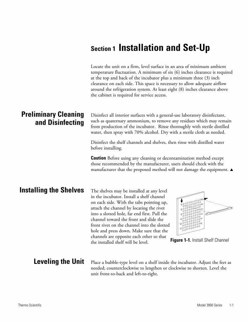
The shelves may be installed at any levelin the incubator. Install a shelf channelon each side. With the tabs pointing up,attach the channel by locating the rivetinto a slotted hole, far end first. Pull thechannel toward the front and slide thefront rivet on the channel into the slottedhole and press down. Make sure that thechannels are opposite each other so thatthe installed shelf will be level.
Place a bubble-type level on a shelf inside the incubator. Adjust the feet asneeded; counterclockwise to lengthen or clockwise to shorten. Level theunit front-to-back and left-to-right.
Installing the Shelves
Preliminary Cleaningand Disinfecting
Figure 1-1. Install Shelf Channel
610105
5/16-18 UNC
STAINLESS STEEL
RIVNUT
3176856
5/16-18 x 1”
HH FULL THREAD
SS CAP SCREW
23036
5/16 INT. TOOTH
LOCKWASHER
1-2 Model 3900 Series Thermo Scientific
Section 1Installation and Set-Up
The humidity reservoir will require approximately three cups (0.710 liter)of water on the initial filling. For best operation of the incubator, sterilizeddistilled, demineralized or de-ionized water should be used in the humidityreservoir. Water purity should be in the resistance range of 50K to 1MOhm/cm, or a conductivity range of 20.0 to 1.0 uS/cm. Refer to ASTMStandard D5391-93 or D4195-88 for measuring water purity.
Distillation systems, as well as some types of reverse osmosis water puritysystems, can produce water in the quality range specified. Tap water is notrecommended as it may contain chlorine, which can deteriorate thestainless steel. Tap water may also have a high mineral content, whichwould produce a build-up of scale in the reservoir. High purity or ultrapure water is not recommended as it is an extremely aggressive solvent andwill deteriorate the stainless steel. High purity water has a resistance ofabove 1M to 18M Ohm. Even high purity water can contain bacteria andorganic contaminants. Water should always be sterilized or treated with adecontaminant, safe for use with stainless steel as well as safe for theproduct, prior to being introduced into the humidity reservoir.
Caution Distilled or de-ionized water used in humidity reservoir must bewithin a water quality resistance range of 50K to 1M Ohm/cm to protectand prolong the life of the stainless steel. Use of water outside the specifiedrange will decrease the operating life of the unit and may void warranty. s
Connect Water Inletfor Humidity System
Installing the WallAnchors
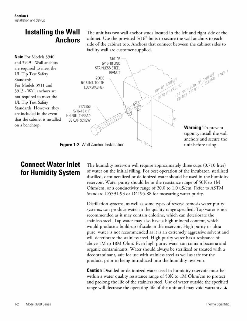
Figure 1-2. Wall Anchor Installation
Warning To preventtipping, install the wallanchors and secure theunit before using.
The unit has two wall anchor studs located in the left and right side of thecabinet. Use the provided 5/16” bolts to secure the wall anchors to eachside of the cabinet top. Anchors that connect between the cabinet sides tofacility wall are customer supplied.
Note For Models 3940and 3949 - Wall anchorsare required to meet theUL Tip Test SafetyStandards.For Models 3911 and3913 - Wall anchors arenot required to meet theUL Tip Test SafetyStandards. However, theyare included in the eventthat the cabinet is installedon a benchtop.
Attaching DrainConnections
Model 3900 Series 1-3Thermo Scientific
Section 1Installation and Set-Up
The water inlet is the 1/8” FPT connection located on the rear top centerof the incubator. For pressurized systems, water inlet pressure must notexceed 40 PSI. A manual shut-off valve should be installed between themain water supply and the incubator. A water strainer is provided that canbe connected to the back of the cabinet if desired.
Caution To prevent mineral buildup on humidity generator walls, it maybe necessary to clean the humidity generator with a non-metallic abrasivepad and flush thoroughly every two to three months. Refer to Section 4,Cleaning the Humidity Steam Generator. s
If an in-house water supply of the required purity range (50K to 1MOhm) is not available, an alternate water supply method can be used. Alarge vented carboy (5 gal. minimum) of water in the required purity rangecan be placed on top of the unit. The provided ¼” hose barb fittingshould be used to connect to the 1/8” FPT water inlet fitting, located onthe rear top center of the incubator.
Note The maximum water consumption of this incubator could be as highas 2 gallons per day. When using an alternate water supply method, it isrecommended that the supply be checked periodically based on sourcevolume.
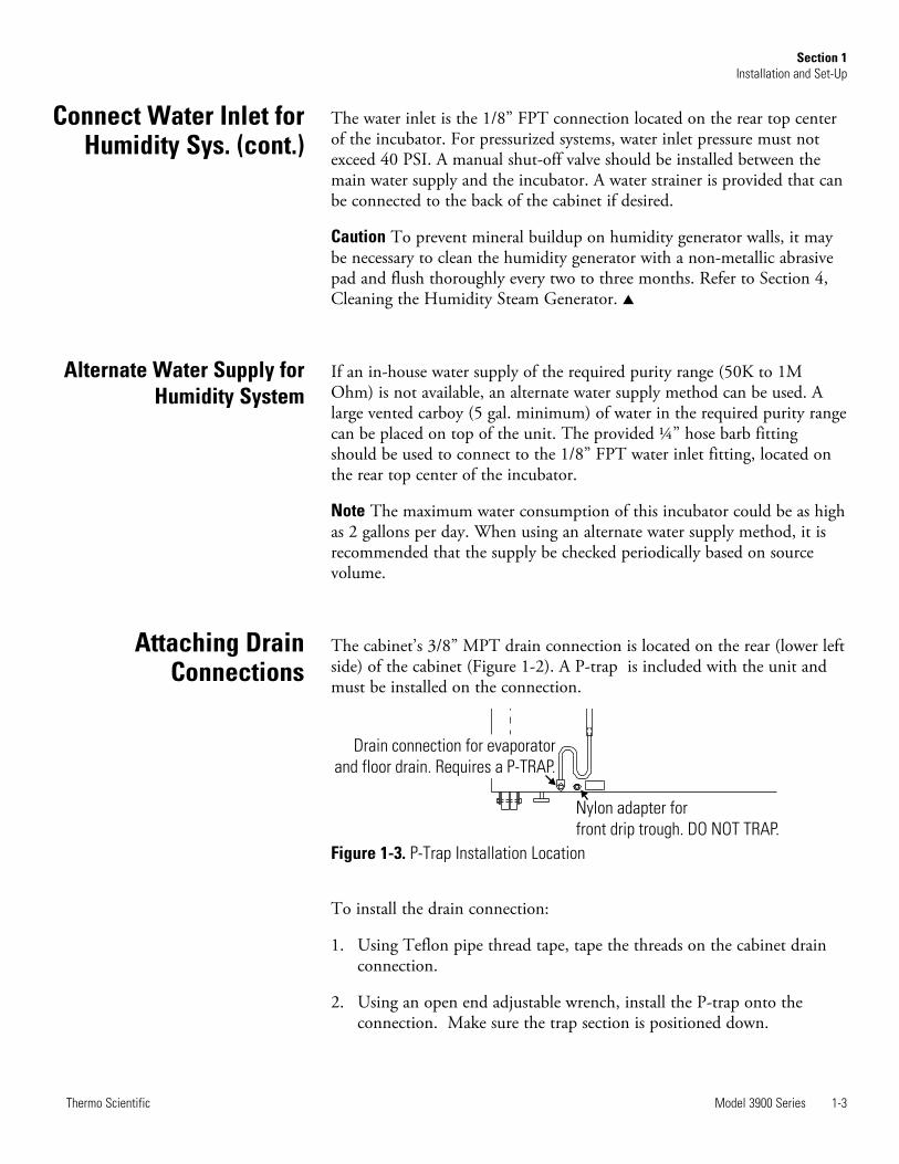
The cabinet’s 3/8” MPT drain connection is located on the rear (lower leftside) of the cabinet (Figure 1-2). A P-trap is included with the unit andmust be installed on the connection.
To install the drain connection:
1. Using Teflon pipe thread tape, tape the threads on the cabinet drainconnection.
2. Using an open end adjustable wrench, install the P-trap onto theconnection. Make sure the trap section is positioned down.
Nylon adapter for
front drip trough. DO NOT TRAP.
Drain connection for evaporator
and floor drain. Requires a P-TRAP.
Figure 1-3. P-Trap Installation Location
Alternate Water Supply forHumidity System
Connect Water Inlet forHumidity Sys. (cont.)
3. Push a piece of 3/8” ID tubing onto the trap and direct the tubing to aconvenient drain. Install a hose clamp on the tubing, if desired. Acondensate evaporator (P/N 1900031) or condensate pump (P/N184062) may also be used.
To connect the nylon adapter from the front drip trough, do not install ap-trap on the nylon adapter (Figure 1-2). Push a piece of 3/8” ID tubingonto the nylon adapter and direct the tubing to a convenient drain. Installa hose clamp on the tubing, if desired.
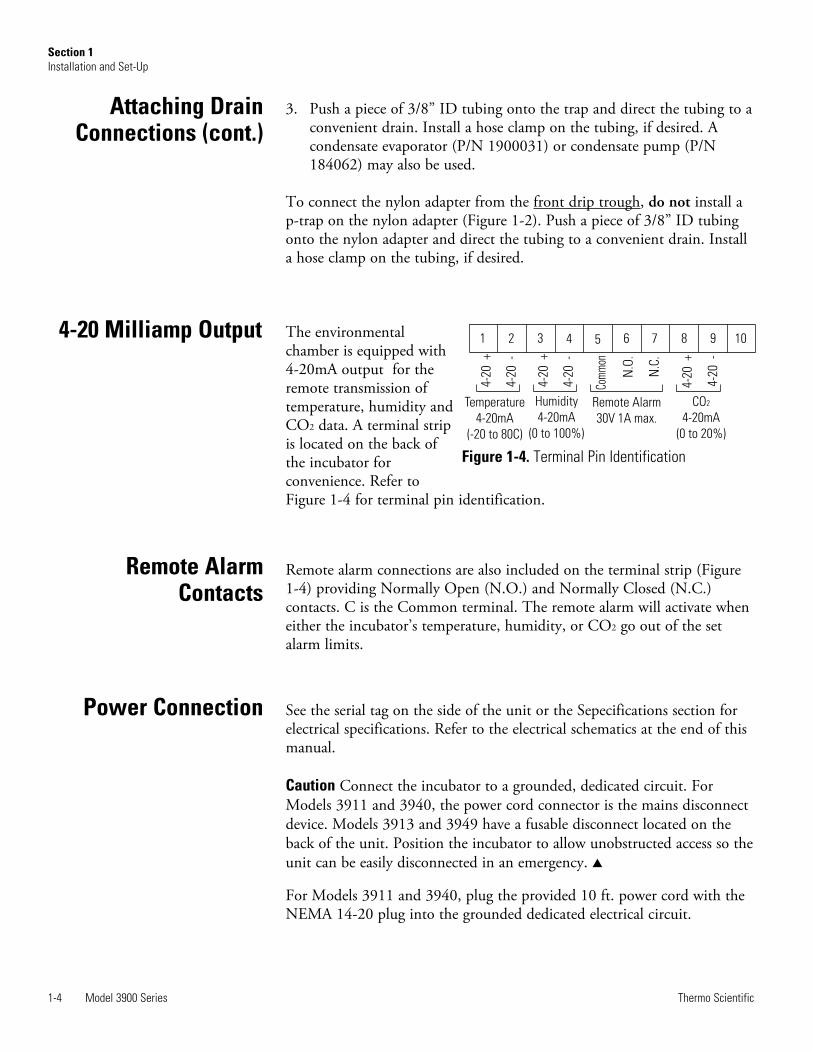
The environmentalchamber is equipped with4-20mA output for theremote transmission oftemperature, humidity andCO2 data. A terminal stripis located on the back ofthe incubator forconvenience. Refer toFigure 1-4 for terminal pin identification.
Remote alarm connections are also included on the terminal strip (Figure1-4) providing Normally Open (N.O.) and Normally Closed (N.C.)contacts. C is the Common terminal. The remote alarm will activate wheneither the incubator’s temperature, humidity, or CO2 go out of the setalarm limits.
See the serial tag on the side of the unit or the Sepecifications section forelectrical specifications. Refer to the electrical schematics at the end of thismanual.
Caution Connect the incubator to a grounded, dedicated circuit. ForModels 3911 and 3940, the power cord connector is the mains disconnectdevice. Models 3913 and 3949 have a fusable disconnect located on theback of the unit. Position the incubator to allow unobstructed access so theunit can be easily disconnected in an emergency. s
For Models 3911 and 3940, plug the provided 10 ft. power cord with theNEMA 14-20 plug into the grounded dedicated electrical circuit.
1-4 Model 3900 Series Thermo Scientific
Section 1Installation and Set-Up
Remote AlarmContacts
Power Connection
4-20 Milliamp Output 1 2 3 4 5 6 7 8 9 10
Temperature
4-20mA
(-20 to 80C)
Remote Alarm
30V 1A max.
CO
4-20mA
(0 to 20%)
2
4-20
+
4-20
-
Com
mon
N.O
.
N.C
.
4-20
+
4-20
-
Humidity
4-20mA
(0 to 100%)
4-20
+
4-20
-
Figure 1-4. Terminal Pin Identification
Attaching DrainConnections (cont.)
When the humidification system is operational, the incubator may bestarted. Preset the controls as follows:
Overtemp Safety Thermostat . . . . . . Fully ClockwiseUndertemp Safety Thermostat . . . Fully CounterclockwiseMain Power Switch . . . . . . . . . . . . . . . . . . . . . . . ONHumidity Controller . . . . . . . . . . . . Desired SetpointTemperature Controller . . . . . . . . . .Desired SetpointDoor Heater . . . . . . . . . . . . . . . . . . 40% (factory set)
For best overall performance of the incubator, the refrigeration switchshould be turned On for most applications. When running Low or Nohumidity at high temperatures, the refrigeration switch may be turned Off.
Caution The defrost switch must be set to “Auto” when the temperaturesetpoint is 10°C, or below. s
Allow the chamber temperature and humidity to stabilize, then set theovertemp safety thermostat as follows:
1. Turn the overtemp control knob slowly counterclockwise until theaudible alarm sounds and the overtemp indicator lights.
2. Turn the overtemp control knob clockwise at least 2°. The alarmshould be silenced and the overtemp indicator light should go out.The overtemp safety thermostat is now set a few degrees above thecontrol temperature setpoint. When the chamber temperature rises tothe overtemp control point, the alarm system will activate, power tothe heaters will shut off, and the chamber temperature will bemaintained at the overtemp control point.
When an overtemp condition occurs, the cause must be determined andcorrected before normal operation under the main temperature controllercan be resumed.
NoteWhen the chamber temperature control setpoint is changed, theovertemp safety thermostat must be reset to accommodate the change. s
Note The overtemp control is not directly calibrated. The numbers on thedial are for reference only. s
Model 3900 Series 1-5Thermo Scientific
Section 1Installation and Set-Up
Set the OvertempSafety Thermostat
Start-Up
Allow the chamber temperature and humidity to stabilize, then set theundertemp safety thermostat as follows:
1. Turn the undertemp control knob slowly clockwise until the audiblealarm sounds and the undertemp indicator lights.
2. Turn the undertemp control knob counterclockwise at least 2° on thescale. The alarm will silence and the undertemp indicator light go out.
The undertemp safety thermostat is now set a few degrees below thecontrol temperature setpoint. When the chamber temperature drops to theundertemp control point, the alarm system activates, power to thecompressor shuts off, and the chamber temperature is maintained at theundertemp control point.
When an undertemp condition occurs, the cause must be determined andcorrected before normal operation under the main temperature controllercan be resumed.
NoteWhen the chamber temperature control setpoint is changed, theundertemp safety thermostat must be reset to accommodate the change. s
Note The undertemp control is not directly calibrated. The numbers onthe dial are for reference only. s
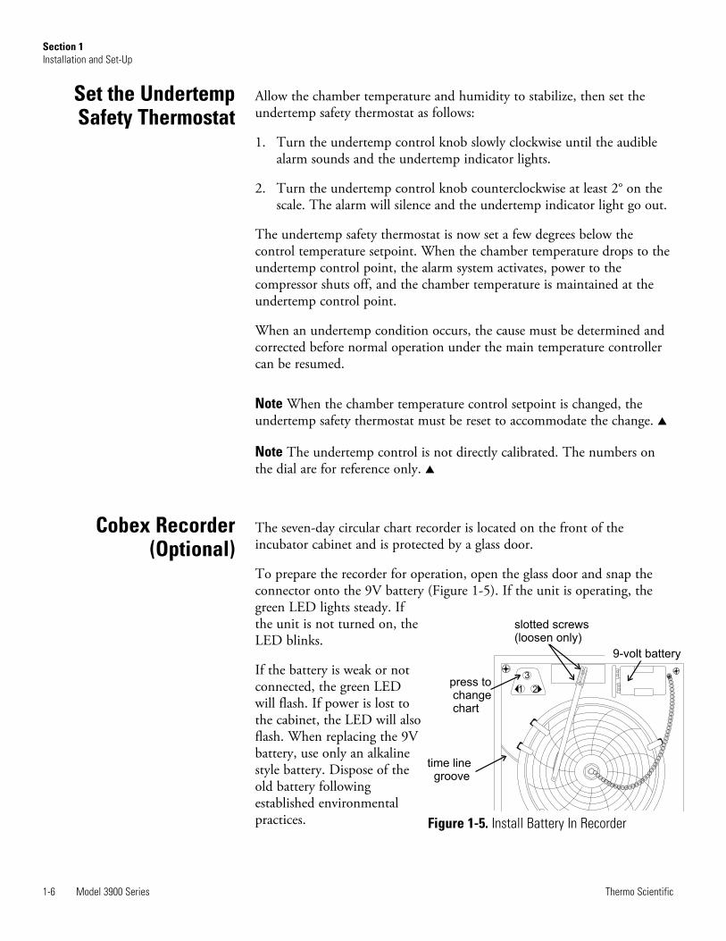
The seven-day circular chart recorder is located on the front of theincubator cabinet and is protected by a glass door.
To prepare the recorder for operation, open the glass door and snap theconnector onto the 9V battery (Figure 1-5). If the unit is operating, thegreen LED lights steady. Ifthe unit is not turned on, theLED blinks.
If the battery is weak or notconnected, the green LEDwill flash. If power is lost tothe cabinet, the LED will alsoflash. When replacing the 9Vbattery, use only an alkalinestyle battery. Dispose of theold battery followingestablished environmentalpractices.
1-6 Model 3900 Series Thermo Scientific
Section 1Installation and Set-Up
1 2
3
time linegroove
press tochangechart
slotted screws(loosen only)
9-volt battery
Figure 1-5. Install Battery In Recorder
Cobex Recorder(Optional)
Set the UndertempSafety Thermostat
Honeywell Recorder(Optional)
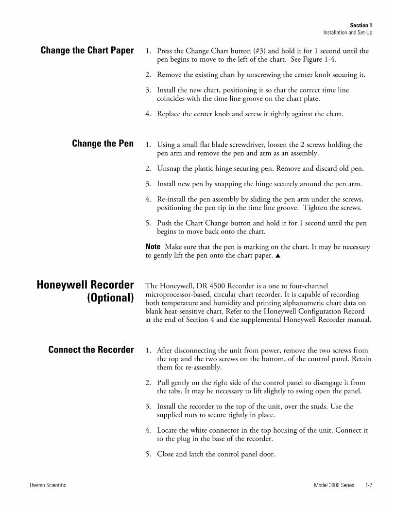
Change the Chart Paper 1. Press the Change Chart button (#3) and hold it for 1 second until thepen begins to move to the left of the chart. See Figure 1-4.
2. Remove the existing chart by unscrewing the center knob securing it.
3. Install the new chart, positioning it so that the correct time linecoincides with the time line groove on the chart plate.
4. Replace the center knob and screw it tightly against the chart.
1. Using a small flat blade screwdriver, loosen the 2 screws holding thepen arm and remove the pen and arm as an assembly.
2. Unsnap the plastic hinge securing pen. Remove and discard old pen.
3. Install new pen by snapping the hinge securely around the pen arm.
4. Re-install the pen assembly by sliding the pen arm under the screws,positioning the pen tip in the time line groove. Tighten the screws.
5. Push the Chart Change button and hold it for 1 second until the penbegins to move back onto the chart.
Note Make sure that the pen is marking on the chart. It may be necessaryto gently lift the pen onto the chart paper. s
The Honeywell, DR 4500 Recorder is a one to four-channelmicroprocessor-based, circular chart recorder. It is capable of recordingboth temperature and humidity and printing alphanumeric chart data onblank heat-sensitive chart. Refer to the Honeywell Configuration Recordat the end of Section 4 and the supplemental Honeywell Recorder manual.
1. After disconnecting the unit from power, remove the two screws fromthe top and the two screws on the bottom, of the control panel. Retainthem for re-assembly.
2. Pull gently on the right side of the control panel to disengage it fromthe tabs. It may be necessary to lift slightly to swing open the panel.
3. Install the recorder to the top of the unit, over the studs. Use thesupplied nuts to secure tightly in place.
4. Locate the white connector in the top housing of the unit. Connect itto the plug in the base of the recorder.
5. Close and latch the control panel door.
Model 3900 Series 1-7Thermo Scientific
Section 1Installation and Set-Up
Change the Pen
Connect the Recorder
1. After making sure the unit is not connected to power, disconnect thedoor plug from the lower left corner of the control panel. Just allow itto hang, still connected to the door.
2. Remove the two screws from the top and the two screws on thebottom, of the control panel. Retain them for re-assembly.
3. Pull gently on the left side of the control panel to disengage it from thetabs. You may need to lift slightly to swing open the panel.
This section applies to units with the IR CO2 option only.
For the most economical use, the liquid CO2 supply tanks should bewithout siphon tubes, so that only CO2 gas enters the incubator injectionsystem. Two tanks may be joined together with a manifold to ensure acontinuous CO2 supply.
Install a two-stage pressure regulator, with indicating gauges, at the supplycylinder outlet. The high-pressure gauge should have an indicating range of0 to 2000 psig to monitor tank pressure. The low-pressure gauge shouldhave an indicating range of 0 to 30 psig to monitor input pressure to theincubator injection system. A suitable two-stage pressure regulator isavailable.
The CO2 source must be regulated at a pressure level of 15, ±5 psig.Higher pressure levels may damage the CO2 control system. The usershould determine the most economical pressure level, between 10 and 20psig appropriate for the desired CO2 percentage in the chamber. Use onlysufficient pressure to maintain recovery time after door openings.
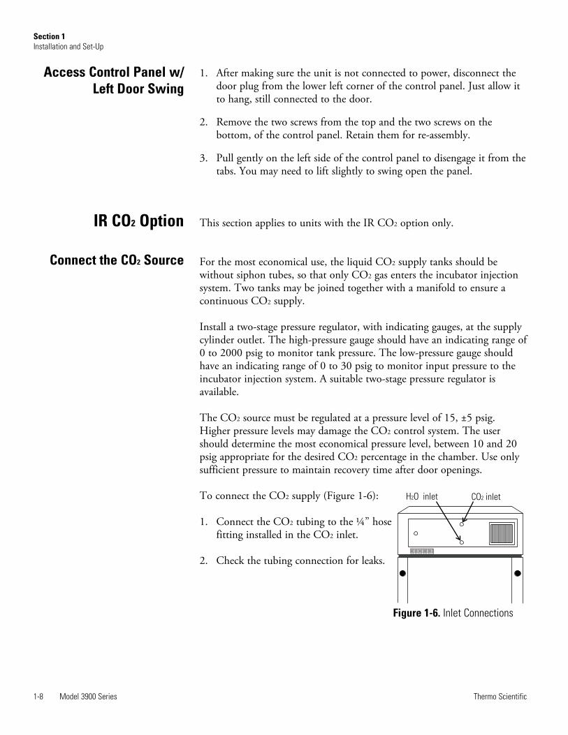
To connect the CO2 supply (Figure 1-6):
1. Connect the CO2 tubing to the ¼” hosefitting installed in the CO2 inlet.
2. Check the tubing connection for leaks.
1-8 Model 3900 Series Thermo Scientific
Section 1Installation and Set-Up
H O inlet2 CO inlet2
Figure 1-6. Inlet Connections
IR CO2 Option
Connect the CO2 Source
Access Control Panel w/Left Door Swing
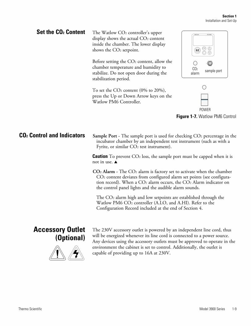
The Watlow CO2 controller's upperdisplay shows the actual CO2 contentinside the chamber. The lower displayshows the CO2 setpoint.
Before setting the CO2 content, allow thechamber temperature and humidity tostabilize. Do not open door during thestabilization period.
To set the CO2 content (0% to 20%),press the Up or Down Arrow keys on theWatlow PM6 Controller.
Sample Port - The sample port is used for checking CO2 percentage in theincubator chamber by an independent test instrument (such as with aFyrite, or similar CO2 test instrument).
Caution To prevent CO2 loss, the sample port must be capped when it isnot in use. s
CO2 Alarm - The CO2 alarm is factory set to activate when the chamberCO2 content deviates from configured alarm set points (see configura-tion record). When a CO2 alarm occurs, the CO2 Alarm indicator onthe control panel lights and the audible alarm sounds.
The CO2 alarm high and low setpoints are established through theWatlow PM6 CO2 controller (A.LO, and A.HI). Refer to theConfiguration Record included at the end of Section 4.
The 230V accessory outlet is powered by an independent line cord, thuswill be energized whenever its line cord is connected to a power source.Any devices using the accessory outlets must be approved to operate in theenvironment the cabinet is set to control. Additionally, the outlet iscapable of providing up to 16A at 230V.
Model 3900 Series 1-9Thermo Scientific
Section 1Installation and Set-Up
CO2 Control and Indicators
Accessory Outlet(Optional)
Set the CO2 Content
sample port
POWER
CO
alarm
2
EZ
WATLOW EZ-ZONE
Figure 1-7. Watlow PM6 Control
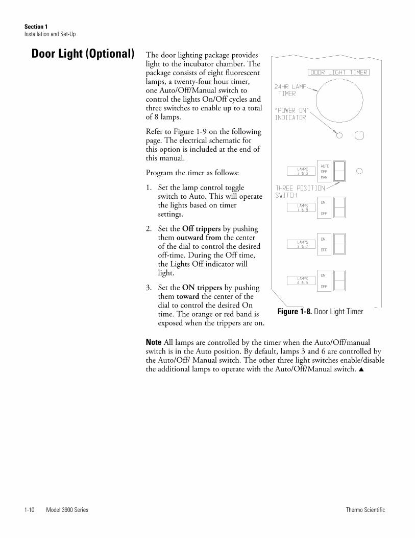
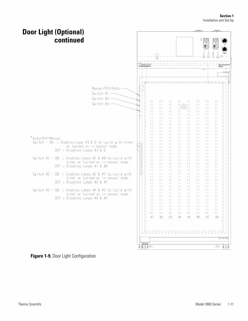
The door lighting package provideslight to the incubator chamber. Thepackage consists of eight fluorescentlamps, a twenty-four hour timer,one Auto/Off/Manual switch tocontrol the lights On/Off cycles andthree switches to enable up to a totalof 8 lamps.
Refer to Figure 1-9 on the followingpage. The electrical schematic forthis option is included at the end ofthis manual.
Program the timer as follows:
1. Set the lamp control toggleswitch to Auto. This will operatethe lights based on timersettings.
2. Set the Off trippers by pushingthem outward from the centerof the dial to control the desiredoff-time. During the Off time,the Lights Off indicator willlight.
3. Set the ON trippers by pushingthem toward the center of thedial to control the desired Ontime. The orange or red band isexposed when the trippers are on.
Note All lamps are controlled by the timer when the Auto/Off/manualswitch is in the Auto position. By default, lamps 3 and 6 are controlled bythe Auto/Off/ Manual switch. The other three light switches enable/disablethe additional lamps to operate with the Auto/Off/Manual switch. s
1-10 Model 3900 Series Thermo Scientific
Section 1Installation and Set-Up
Figure 1-8. Door Light Timer
Door Light (Optional)
Model 3900 Series 1-11Thermo Scientific
Section 1Installation and Set-Up
Figure 1-9. Door Light Configuration
Door Light (Optional)continued
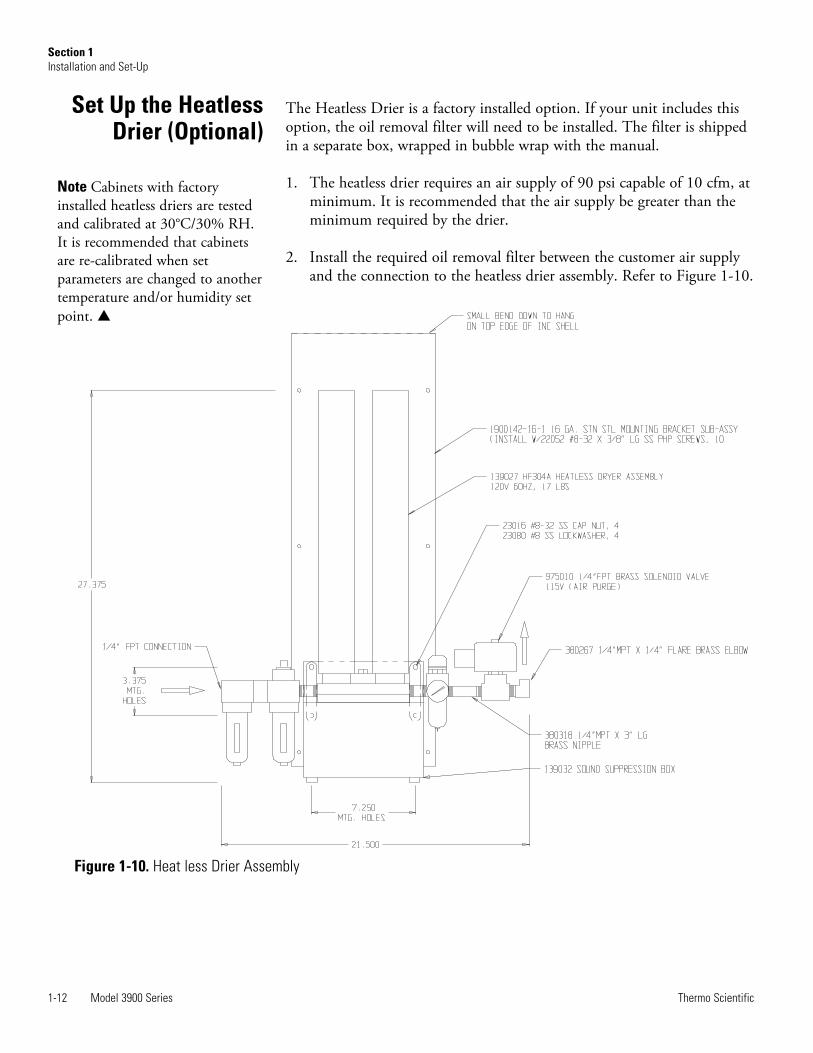
The Heatless Drier is a factory installed option. If your unit includes thisoption, the oil removal filter will need to be installed. The filter is shippedin a separate box, wrapped in bubble wrap with the manual.
1. The heatless drier requires an air supply of 90 psi capable of 10 cfm, atminimum. It is recommended that the air supply be greater than theminimum required by the drier.
2. Install the required oil removal filter between the customer air supplyand the connection to the heatless drier assembly. Refer to Figure 1-10.
1-12 Model 3900 Series Thermo Scientific
Section 1Installation and Set-Up
Set Up the HeatlessDrier (Optional)
Figure 1-10. Heat less Drier Assembly
Note Cabinets with factoryinstalled heatless driers are testedand calibrated at 30°C/30% RH.It is recommended that cabinetsare re-calibrated when setparameters are changed to anothertemperature and/or humidity setpoint. s
Model 3900 Series 2-1Thermo Scientific
Section 2 Start-Up and Operation
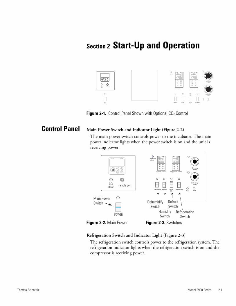
Figure 2-1. Control Panel Shown with Optional CO2 Control
Main Power Switch and Indicator Light (Figure 2-2)The main power switch controls power to the incubator. The mainpower indicator lights when the power switch is on and the unit isreceiving power.
Refrigeration Switch and Indicator Light (Figure 2-3)The refrigeration switch controls power to the refrigeration system. Therefrigeration indicator lights when the refrigeration switch is on and thecompressor is receiving power.
Control Panel
sample port
POWER
CO
alarm
2
EZ
WATLOW EZ-ZONE
Heat
Under tempsafety
Cool
Temperature control
Humidity DefrostOff
Refrigeration
humidityalarm
Humidity control
Dehumidify
Auto
Over tempsafety
-65
-55
-25
-45
-35
-15 -5-5 515
25
35
45
5565
15
-5
5
25
35 45 5565
75
85
95
105-15
Dehumidify
Switch
Humidify
Switch
Defrost
Switch
Refrigeration
Switch
Figure 2-2. Main Power Figure 2-3. Switches
sample portCo2
alarm
EZ
WATLOW EZ-ZONE
Overtemperature
Safety
Undertemperature
Safety
Main PowerSwitch
2-2 Model 3900 Series Thermo Scientific
Section 2Start-Up and Operation
Control Panel(continued)
Defrost Switch and Indicator Light (Figure 2-3)The defrost switch controls power to the defrost system. Setting thedefrost switch to Auto will provide two 15-minute defrost cycles duringa twenty-four hour period. The defrost indicator lights when the defrostswitch is on and the incubator is in a defrost cycle.
Caution The defrost switch must be set to Auto when the temperaturesetpoint is 10°C, or below. s
Humidity Switch and Indicator (Figure 2-3)The humidity switch controls the power to the humidification systemcircuit. The humidity indicator light will cycle as the controller togglesbetween humidify and dehumidify.
Dehumidify Switch and Indicator (Figure 2-3)The dehumidify switch is used with the optional heatless drier P/N1900139 to provide dehumidification. The heatless drier injects dry airinto the incubator chamber as needed, to maintain humidity levels.When controlling humidity, the dehumidification switch should be inthe ON position for most applications. The dehumidification light willcycle on and off as the humidity controller toggles between humidifyand dehumidify.
Heat Indicator (Figure 2-4)The Heat Indicator illuminates when the heater activates.
Cool Indicator (Figure 2-4)The Cool Indicator illuminates when the refrigeration system activates.
Overtemp Safety Control, Indicator Light, Audible Alarm (Figure 2-4)The overtemp safety thermostat should be set slightly above the operat-ing temperature of the incubator. In the event of an overtemp condition,the overtemp safety thermostat:• Activates the audible alarm and the overtemp indicator light.• Interrupts power to the heaters and maintain the incubator’s cabinettemperature at the overtemp safety control point.
Note The overtemp control is not directly calibrated. The numbers on thedial are for reference only.
If an overtemp condition occurs, the alarm can only be silenced by raisingthe overtemp safety thermostat setting. However, the cause of the problemmust be determined and corrected before normal operation under themain temperature controller is resumed.
Model 3900 Series 2-3Thermo Scientific
Section 1Start-Up and Operation
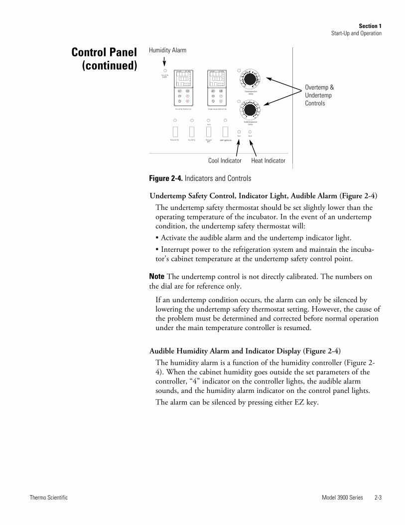
Figure 2-4. Indicators and Controls
Undertemp Safety Control, Indicator Light, Audible Alarm (Figure 2-4)The undertemp safety thermostat should be set slightly lower than theoperating temperature of the incubator. In the event of an undertempcondition, the undertemp safety thermostat will:• Activate the audible alarm and the undertemp indicator light.• Interrupt power to the refrigeration system and maintain the incuba-tor’s cabinet temperature at the undertemp safety control point.
Note The undertemp control is not directly calibrated. The numbers onthe dial are for reference only.
If an undertemp condition occurs, the alarm can only be silenced bylowering the undertemp safety thermostat setting. However, the cause ofthe problem must be determined and corrected before normal operationunder the main temperature controller is resumed.
Audible Humidity Alarm and Indicator Display (Figure 2-4)The humidity alarm is a function of the humidity controller (Figure 2-4). When the cabinet humidity goes outside the set parameters of thecontroller, “4” indicator on the controller lights, the audible alarmsounds, and the humidity alarm indicator on the control panel lights. The alarm can be silenced by pressing either EZ key.
EZ-ZONE
Overtemperature
Safety
Undertemperature
Safety
Control Panel(continued)
Humidity Alarm
Cool Indicator Heat Indicator
Overtemp &UndertempControls
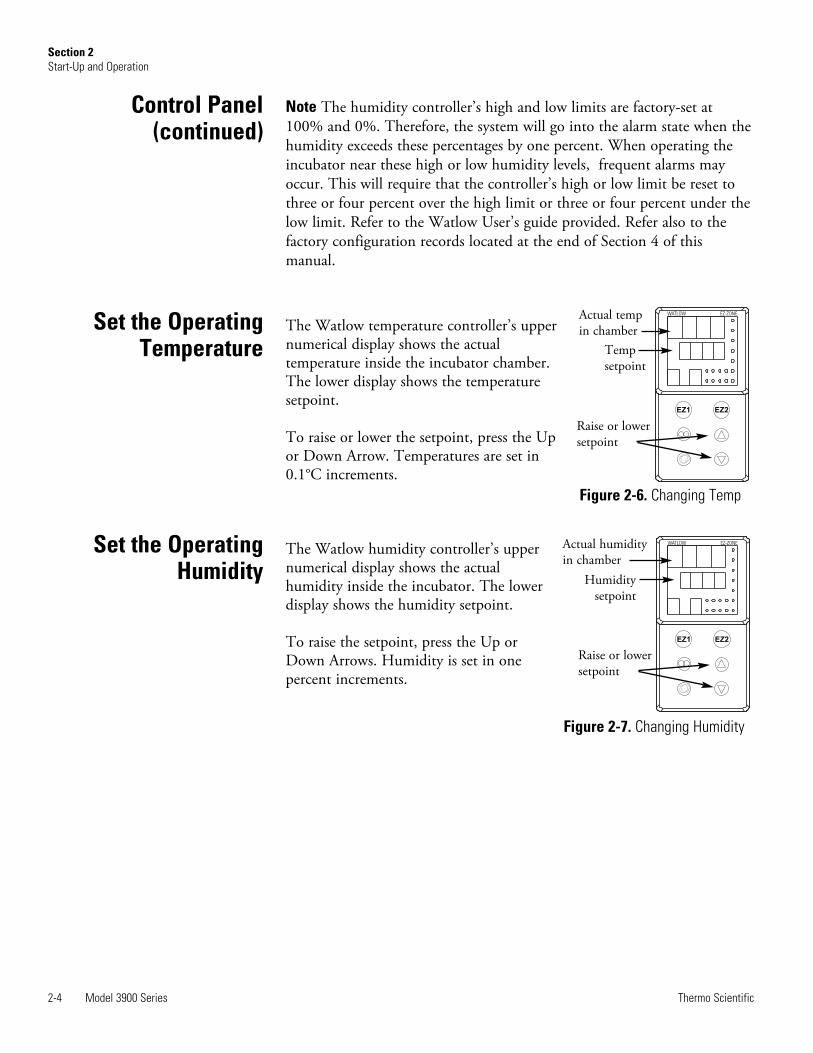
Note The humidity controller’s high and low limits are factory-set at100% and 0%. Therefore, the system will go into the alarm state when thehumidity exceeds these percentages by one percent. When operating theincubator near these high or low humidity levels, frequent alarms mayoccur. This will require that the controller’s high or low limit be reset tothree or four percent over the high limit or three or four percent under thelow limit. Refer to the Watlow User’s guide provided. Refer also to thefactory configuration records located at the end of Section 4 of thismanual.
The Watlow temperature controller’s uppernumerical display shows the actualtemperature inside the incubator chamber.The lower display shows the temperaturesetpoint.
To raise or lower the setpoint, press the Upor Down Arrow. Temperatures are set in0.1°C increments.
The Watlow humidity controller’s uppernumerical display shows the actualhumidity inside the incubator. The lowerdisplay shows the humidity setpoint.
To raise the setpoint, press the Up orDown Arrows. Humidity is set in onepercent increments.
2-4 Model 3900 Series Thermo Scientific
Section 2Start-Up and Operation
Set the OperatingTemperature
EZ2EZ1
WATLOW EZ-ZONE
Figure 2-6. Changing Temp
Set the OperatingHumidity
EZ2EZ1
WATLOW EZ-ZONE
Figure 2-7. Changing Humidity
Control Panel(continued)
Actual tempin chamber
Tempsetpoint
Raise or lowersetpoint
Actual humidityin chamber
Humiditysetpoint
Raise or lowersetpoint

Air exchange for the incubator is regulated through the manuallyadjustable intake and exhaust ventilator caps located on the top of thecabinet. When viewed from the front of the incubator, the intake cap is onthe left and the exhaust cap is on the right. The ventilator caps may beopened by turning counterclockwise, and closed by turning clockwise.
For optimum performance of the unit, the vent caps should be closed at alltimes.
The optional heatless drier (P/N 1900139) provides dehumidification forthe incubator chamber (oil removal filter must be installed, see Section 1).The dehumidify switch must be turned On for the drier to operate. Thedrier is controlled with the humidity controller and will purge dry air intothe incubator as needed to maintain the control set point.
Note Cabinets with factory installed heatless driers are tested andcalibrated at 30°C/30% RH. It is recommended that cabinets are re-calibrated when set parameters are changed to another temperature and/orhumidity set point.
Model 3900 Series 2-5Thermo Scientific
Section 2Start-Up and Operation
Air ExchangeVentilator Caps
Set Up the HeatlessDrier (Optional)
Model 3900 Series 3-1Thermo Scientific
Section 3 Routine Maintenance
Warning De-energize all potential sources of energy to this unit andlockout/tagout their controls. (O.S.H.A. Regulation, Section 1910-147.) s
The continued cleanliness of the stainless steel used in this unit has a directeffect on the appearance and operation of the unit. Use the mildestcleaning procedure that will do the job effectively. Clean the outside of theincubator with soap and water or with any non-abrasive commercial spraycleaner. Clean the inside of the chamber with alcohol and/or soap andwater. Disinfect the interior panels with a general use laboratorydisinfectant, diluted according to the manufacturer’s instructions. Rinsethe surface thoroughly after each cleaning and wipe the surfaces dry.Always rub in the direction of the finish polish lines.
Caution Do not use chlorinated solvents on stainless steel as they can causerusting and pitting. s
Caution Do not use volatile or aromatic solvents for cleaning inside thecabinet as their residue can contaminate the cabinet environment. s
The Thermopane glass door may be cleaned with commercial glass cleaneror with a solution of ammonia and water.
Depending on the quality of water used in the humidification system, itmay be necessary to clean the humidity generator every 2 to 3 months.Refer to Section 4 for cleaning instructions.
Maintaining theHumidity Generator
3-2 Model 3900 Series Thermo Scientific
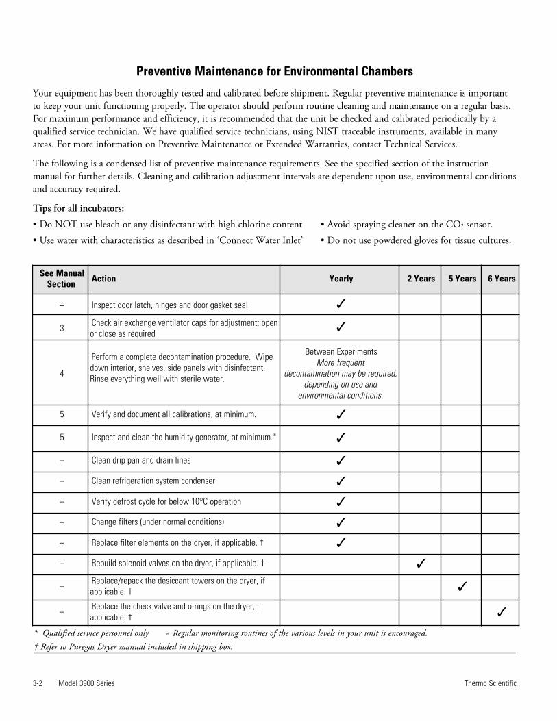
Preventive Maintenance for Environmental Chambers
* Qualified service personnel only ~ Regular monitoring routines of the various levels in your unit is encouraged.† Refer to Puregas Dryer manual included in shipping box.
See ManualSection Action Yearly 2 Years 5 Years 6 Years
-- Inspect door latch, hinges and door gasket seal 3
3 Check air exchange ventilator caps for adjustment; openor close as required
3
4
Perform a complete decontamination procedure. Wipedown interior, shelves, side panels with disinfectant.Rinse everything well with sterile water.
Between ExperimentsMore frequent
decontamination may be required,depending on use and
environmental conditions.
5 Verify and document all calibrations, at minimum. 3
5 Inspect and clean the humidity generator, at minimum.* 3
-- Clean drip pan and drain lines 3
-- Clean refrigeration system condenser 3
-- Verify defrost cycle for below 10°C operation 3
-- Change filters (under normal conditions) 3
-- Replace filter elements on the dryer, if applicable. † 3
-- Rebuild solenoid valves on the dryer, if applicable. † 3
-- Replace/repack the desiccant towers on the dryer, ifapplicable. † 3
-- Replace the check valve and o-rings on the dryer, ifapplicable. † 3
Your equipment has been thoroughly tested and calibrated before shipment. Regular preventive maintenance is importantto keep your unit functioning properly. The operator should perform routine cleaning and maintenance on a regular basis.For maximum performance and efficiency, it is recommended that the unit be checked and calibrated periodically by aqualified service technician. We have qualified service technicians, using NIST traceable instruments, available in manyareas. For more information on Preventive Maintenance or Extended Warranties, contact Technical Services.
The following is a condensed list of preventive maintenance requirements. See the specified section of the instructionmanual for further details. Cleaning and calibration adjustment intervals are dependent upon use, environmental conditionsand accuracy required.
Tips for all incubators:
• Do NOT use bleach or any disinfectant with high chlorine content • Avoid spraying cleaner on the CO2 sensor.
• Use water with characteristics as described in ‘Connect Water Inlet’ • Do not use powdered gloves for tissue cultures.
Fuse Replacement
Over/UndertempProbe and Thermostat
Model 3900 Series 4-1Thermo Scientific
Section 4 Service
Caution Service must be performed by qualified service personnel only! s
Warning De-energize all potential sources of energy to this unit andlockout/tagout their controls. s
To gain access to the electrical components, remove the two screws locatedon the left side of the control panel with a Phillips screwdriver. Thecontrol panel is hinged and will swing open.
Qualified service personnel are required to replace any fuses. See drawing3940-71-0-D (toward the end of this manual) for fuse location and type.
1. Remove the incubator top right side air dam by removing the screwsholding it in place.
2. Remove the top three screws from the top of the right duct cover.
3. Lean the duct sheet out, and remove the Permagum seal from aroundthe probe access hole.
4. Remove the 15” copper capillary overtemp probe by extracting twoplastic clips that hold the probe in place.
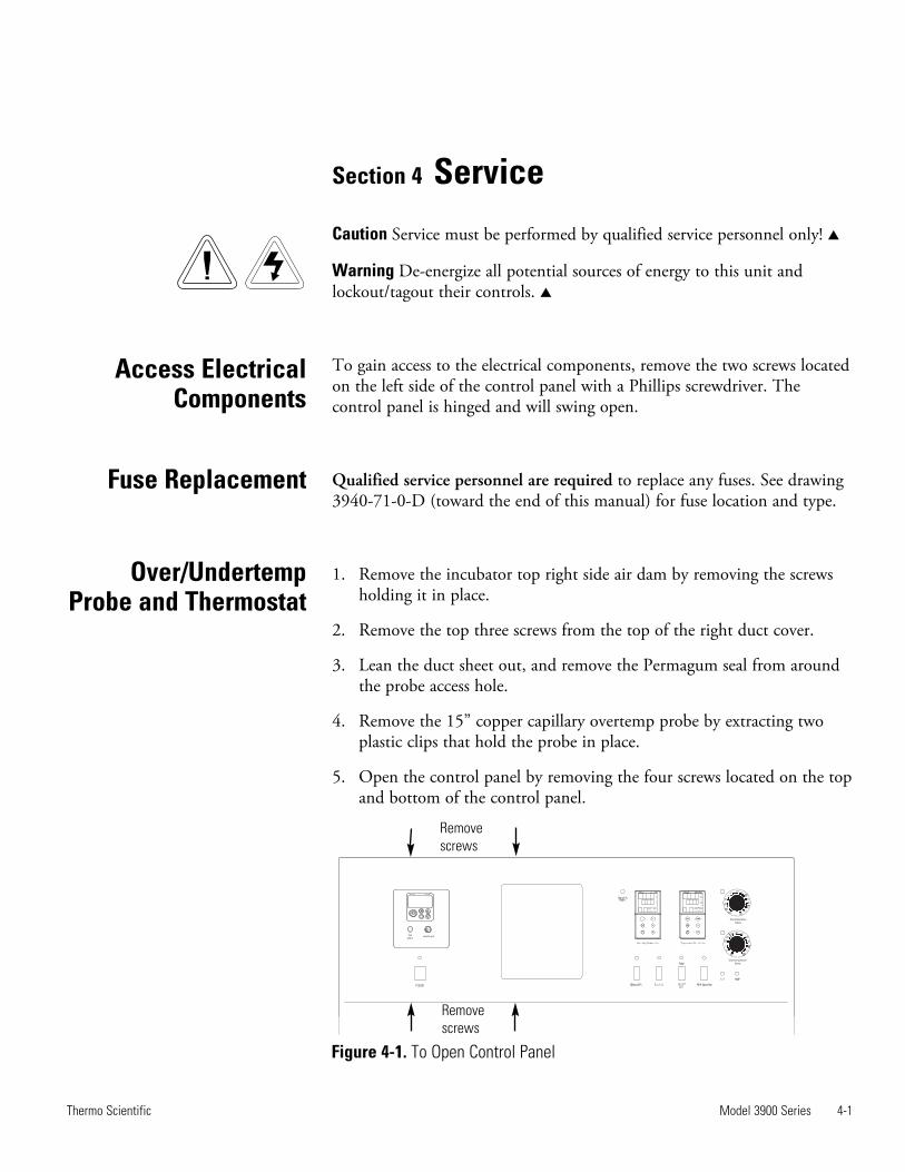
5. Open the control panel by removing the four screws located on the topand bottom of the control panel.
sample portCo2
alarm
EZ
WATLOW EZ-ZONE
Overtemperature
Safety
Undertemperature
Safety
Figure 4-1. To Open Control Panel
Access ElectricalComponents
Removescrews
Removescrews
4-2 Model 3900 Series Thermo Scientific
Section 4Service
Humidity/TempSensor
6. Pull the probe up through the access hole and into the control panel.
7. Follow the wires from the probe to the thermostat mounted on thecontrol panel. Clip the plastic ties holding the overtemp cable to theexisting wiring.
8. Pull the overtemp knob on the control panel off.
9. Remove the two screws that hold the overtemp assembly to the controlpanel.
10. Disconnect the two wires from the back of the thermostat assembly.
11. Pull the entire assembly from the panel, and remove the unit.
12. Replace the thermostat and probe.
13. Re-assemble in reverse order.
Note Reseal probe access hole with Permagum and tie-wrap overtempcable to existing wires after replacing probe.
1. Follow Steps 1-6 from ‘Over/Undertemp Probe and Thermostat’section to locate and remove the probe from the chamber.
2. Clip any plastic ties securing the probe wiring. Disconnect the probe.
3. Install the replacement probe in the chamber. When replacing thehumidity sensor, be sure to mount the probe at the same angle asoriginally mounted.
4. Route the probe wire through the access hole into the control housing.
5. Connect the probe to the appropriate controller wiring.
6. Reseal the probe access hole with Permagum and tie-wrap the probewire to existing wires.
Over/Undertemp Probeand Thermostat (cont.)

Model 3900 Series 4-3Thermo Scientific
Section 4Service
The Watlow temperature and humidity controllers have been set at thefactory to operate the incubator within the specifications listed in theSpecifications section of this manual. Reference copies of the Watlowconfiguration records are included at the end of this section.
To prevent tampering, software lockouts are employed in the system.These lockouts must only be removed by persons skilled in configuringcontroller software.
Caution Re-programming either the temperature or humidity controllersalters the factory defaults and will seriously alter the performance of theincubator. This may also void the warranty. Do not re-configure thecontrollers without first consulting the Technical Services Department. s
1. Press the Advance and Infinity keys at thesame time and hold them for about sixseconds. The word “Fcty” (factory) willappear in the bottom display. If numbersin the bottom display begin to scroll up ordown, the keys have not been pressedsimultaneously. Try again.
2. Press the Up Arrow until “LoC” (lock)appears in the upper display. The word“Fcty” will remain in the lower display(Figure 4-2).
3. Press the Advance key to scroll through themenus as follows:
Program Humidity/Temp Controllers
Remove Software Lockout
Press
(6 sec)
Factory
Lock
EZ2EZ1
WATLOW EZ-ZONE
E
Figure 4-2. Displays
Lower display Upper display Keystrokes
LoC.o 1 Change to 3 = unlocked
LoC.P 1 No changes required
PAS.E 1 No changes required
rLoC 1 Change to 5 = unlocked
SLoC 1 Change to 5 = unlocked
Controller Configuration
To turn the software lockout back On:
1. Set Lock values back to previous setting. See ‘Remove SoftwareLockout’ above.
The Watlow PM Temperature and Humidity Controllers have beenconfigured at the factory. Copies of the Watlow Configuration records areincluded at the end of this section.
Caution Do not re-configure the controller without first consulting theTechnical Services department. s
It may be necessary to calibrate the temperature or humidity controllers tomatch an independent temperature or humidity sensor. To do so, followthe next few steps.
1. Perform the “Remove Software Lockout’ procedure in this section.
2. Suspend an independent, calibrated sensor(s) in the center of theinterior chamber.
3. Allow approximately 30 minutes for the incubator to stabilize.
4. Press Up and Down Arrow keys simultaneously for 3 seconds. Theword “OPEr” appears in the lower display.
5. Press Down Arrow until “Ai” appears in the upper display.
6. Press the Advance key until “i.CA” appears in the lower display. PressUp or Down Arrow key to either add or subtract an offset value. Thisvalue is the difference between the actual value shown on thecontroller, and the reference sensor value.
7. Press the Infinity key until the display reverts to normal operation.
8. Perform the ‘Restore Software Lockout’ procedure in this section.
4-4 Model 3900 Series Thermo Scientific
Section 4Service
Offset Calibration(Temp/Humidity)
Restore Software Lockout
1. Open the incubator door, and locate the probe mounting plateattached to the center of the right interior wall. Remove the mountingplate.
2. The recorder probe is attached to the lower end of the back of themounting plate. Remove the probe by carefully sliding it out of thehousing.
3. Remove the screws securing the right side air dam.
4. Remove the top three screws on both edges of the right duct sheet.
5. Lean the duct sheet out in order to remove the Permagum seal fromaround the probe access hole.
6. Remove the four screws located on the top and bottom of the controlpanel and open the control panel door. Remove any Permagum fromaround the access hole.
7. Pull the probe(s) carefully up through the hole.
8. Follow the probe cable(s) to the back of the recorder, and carefully clipany plastic ties holding the cable(s) to other wiring.
9. Remove the four screws securing the recorder and pull it carefully outfrom the front of the control panel.
10. Replace the recorder with the correct part.
NoteWhen replacing the recorder and probe(s), retie the probe cable(s) tothe existing wires.
Place an accurate thermometer(s) in the chamber next to the recorder’sprobe(s). After about three minutes, compare the thermometer with thechart recorder. For 2 pen operations, also compare the secondthermometer.
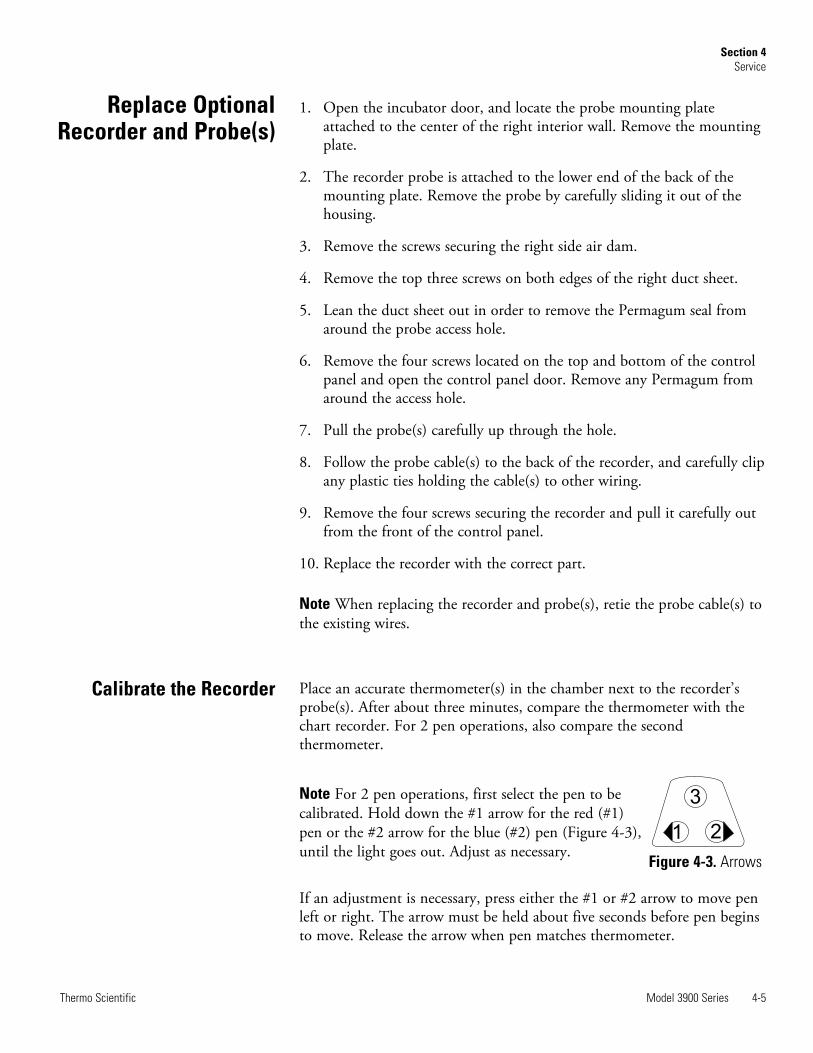
Note For 2 pen operations, first select the pen to becalibrated. Hold down the #1 arrow for the red (#1)pen or the #2 arrow for the blue (#2) pen (Figure 4-3),until the light goes out. Adjust as necessary.
If an adjustment is necessary, press either the #1 or #2 arrow to move penleft or right. The arrow must be held about five seconds before pen beginsto move. Release the arrow when pen matches thermometer.
Model 3900 Series 4-5Thermo Scientific
Section 4Service
Replace OptionalRecorder and Probe(s)
Calibrate the Recorder
1 2
3
Figure 4-3. Arrows
Warning High voltage is present behind control panel. Servicing must beperformed only by qualified electrical service personnel. s
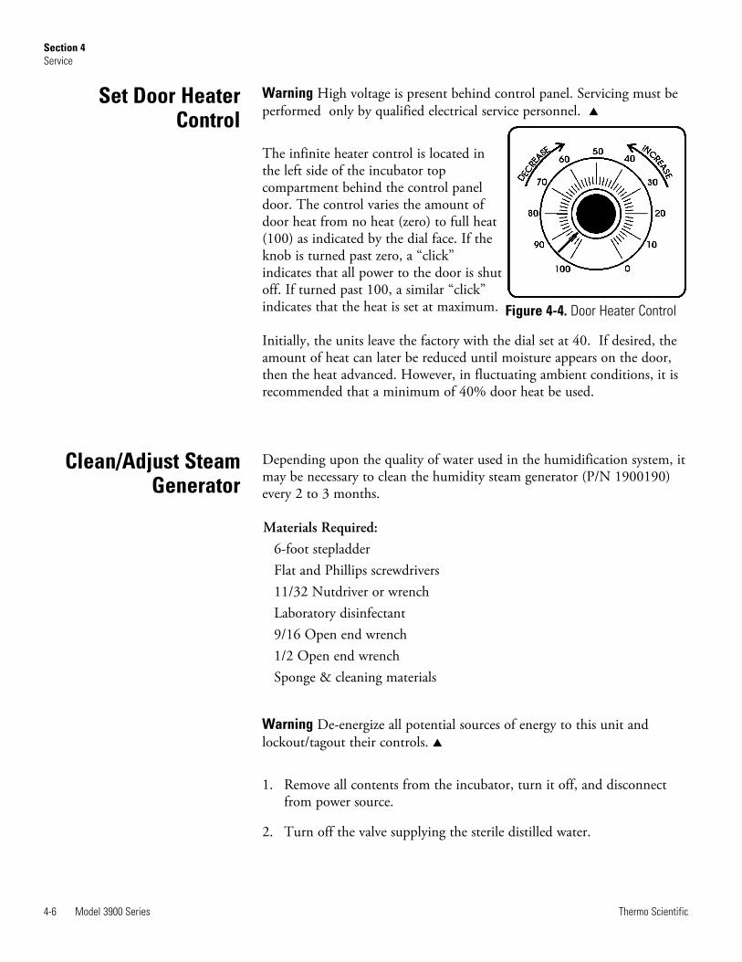
The infinite heater control is located inthe left side of the incubator topcompartment behind the control paneldoor. The control varies the amount ofdoor heat from no heat (zero) to full heat(100) as indicated by the dial face. If theknob is turned past zero, a “click”indicates that all power to the door is shutoff. If turned past 100, a similar “click”indicates that the heat is set at maximum.
Initially, the units leave the factory with the dial set at 40. If desired, theamount of heat can later be reduced until moisture appears on the door,then the heat advanced. However, in fluctuating ambient conditions, it isrecommended that a minimum of 40% door heat be used.
Depending upon the quality of water used in the humidification system, itmay be necessary to clean the humidity steam generator (P/N 1900190)every 2 to 3 months.
Materials Required:6-foot stepladderFlat and Phillips screwdrivers11/32 Nutdriver or wrenchLaboratory disinfectant9/16 Open end wrench1/2 Open end wrenchSponge & cleaning materials
Warning De-energize all potential sources of energy to this unit andlockout/tagout their controls. s
1. Remove all contents from the incubator, turn it off, and disconnectfrom power source.
2. Turn off the valve supplying the sterile distilled water.
4-6 Model 3900 Series Thermo Scientific
Section 4Service
Set Door HeaterControl
Figure 4-4. Door Heater Control
Clean/Adjust SteamGenerator
3. From the stepladder, remove the eight screws securing the top of theincubator cabinet.
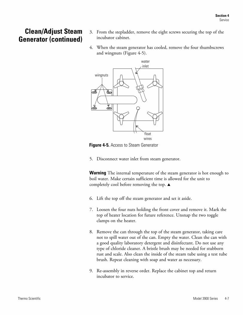
4. When the steam generator has cooled, remove the four thumbscrewsand wingnuts (Figure 4-5).
5. Disconnect water inlet from steam generator.
Warning The internal temperature of the steam generator is hot enough toboil water. Make certain sufficient time is allowed for the unit tocompletely cool before removing the top. s
6. Lift the top off the steam generator and set it aside.
7. Loosen the four nuts holding the front cover and remove it. Mark thetop of heater location for future reference. Unsnap the two toggleclamps on the heater.
8. Remove the can through the top of the steam generator, taking carenot to spill water out of the can. Empty the water. Clean the can witha good quality laboratory detergent and disinfectant. Do not use anytype of chloride cleaner. A bristle brush may be needed for stubbornrust and scale. Also clean the inside of the steam tube using a test tubebrush. Repeat cleaning with soap and water as necessary.
9. Re-assembly in reverse order. Replace the cabinet top and returnincubator to service.
Model 3900 Series 4-7Thermo Scientific
Section 4Service
Clean/Adjust SteamGenerator (continued)
wingnuts
water
inlet
float
wires
Figure 4-5. Access to Steam Generator
If it should become necessary to calibrate the CO2 controller, perform theprocedures on Pages 4-3 through 4-4.
Start from the standard operating display (setpoint in bottom display,actual CO2 reading in the upper display).
The procedure for changing PID tuning values follows.
1. Remove software lockout, if not already performed.
2. From home screen, press and hold the “UP” and “DOWN” arrow keysuntil the display reads “Oper” in the lower display and “Ai” in theupper display.
3. Press the “DOWN” arrow key until “LOOP” appears in the upperdisplay.
4. Press the “ADVANCE” key until “h.Pd” appears in the lower display.
5. Press the “UP” and/or “DOWN” arrow keys to set the value in theupper display.
6. Press the “ADVANCE” key until “c.Pd” appears in the lower display.
7. Press the “UP” and/or “DOWN” arrow keys to set the value in theupper display.
8. Press the “ADVANCE” key until “ti” appears in the lower display.
9. Press the “UP” and/or “DOWN” arrow keys to set the value in theupper display.
4-8 Model 3900 Series Thermo Scientific
Section 4Service
CO2 ControllerCalibration
EZ
WATLOW EZ-ZONE
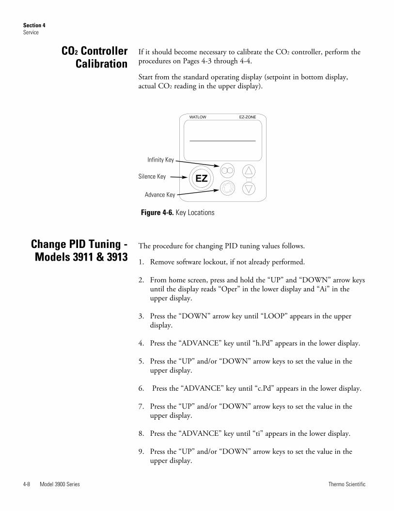
Figure 4-6. Key Locations
Infinity Key
Advance Key
Silence Key
Change PID Tuning -Models 3911 & 3913
10. Press the “ADVANCE” key until “td” appears in the lower display.
11. Press the “UP” and/or “DOWN” arrow keys to set the value in theupper display.
12. Press the “Infinity” key to return to home screen.
13. Return software lockout to its prior settings.
If the above RH PID parameters do not provide the desired control, theRH controller has an Auto Tune feature that can be initiated. Pleasefollow the Watlow PM Control Auto Tune procedure below.
Prior to performing an RH controller auto tune, heat output 2 in the RHcontroller should be configured to have a minimum output of 10% due toheater lag in the RH system. Additionally, the cabinet should be runninga minimum of 24 hours at the desired temperature control setpoint. Thiswill help ensure the steam generator is at a good operating temperatureand the cabinet has reached equilibrium before the auto tune is performed.See procedure below for setting the minimum output low setting to 10%in the RH controller.
Changing RH Control Output 2 Minimum Output to 10%
1. Remove software lockout.
2. Go into SET UP menu by holding the up and down arrow keys for 6seconds. (Lower display reads “Set”, upper display “Ai”)
3. Go to OUTPUT menu by pressing the down arrow key until “OtPt”appears in the upper display.
4. Press the ADVANCE key once (lower display reads “OtPt” and upperdisplay “1”),
5. Press the up arrow key once (lower display reads “OtPt”, upper display“2”).
6. Press the ADVANCE key. The lower display reads “o.Lo”. Press theup arrow key until the upper display reads “10”.
7. Press the INFINITY key several times until the control returns tonormal display.
Note RH control minimum output value should remain at 10% afterperforming Auto Tune. This provides tighter RH control for mostsettings.
Model 3900 Series 4-9Thermo Scientific
Section 4Routine Maintenance
Watlow PM ControlAuto Tune
Change PID Tuning -Models 3911 & 3913
Auto Tune Procedure
1. Remove software lockout, if not already performed.
2. From home screen, press and hold the up and down arrow keys untilthe display reads “Oper” in the lower display and “Ai” in the upperdisplay.
3. Press the down arrow key until “LOOP” appears in the upper display.
4. Press the ADVANCE key until “A.Tun” appears in the lower display.
5. Press the up arrow key until “YES” appears in the upper display.
6. Press the INFINITY key to return to home screen.
The lower display flashes “tUNE” until Auto Tune has successfullycompleted.
4-10 Model 3900 Series Thermo Scientific
Section 4Routine Maintenance
Watlow PM ControlAuto Tune (continued)
Model 3900 Series 4-11Thermo Scientific
Section 4Service
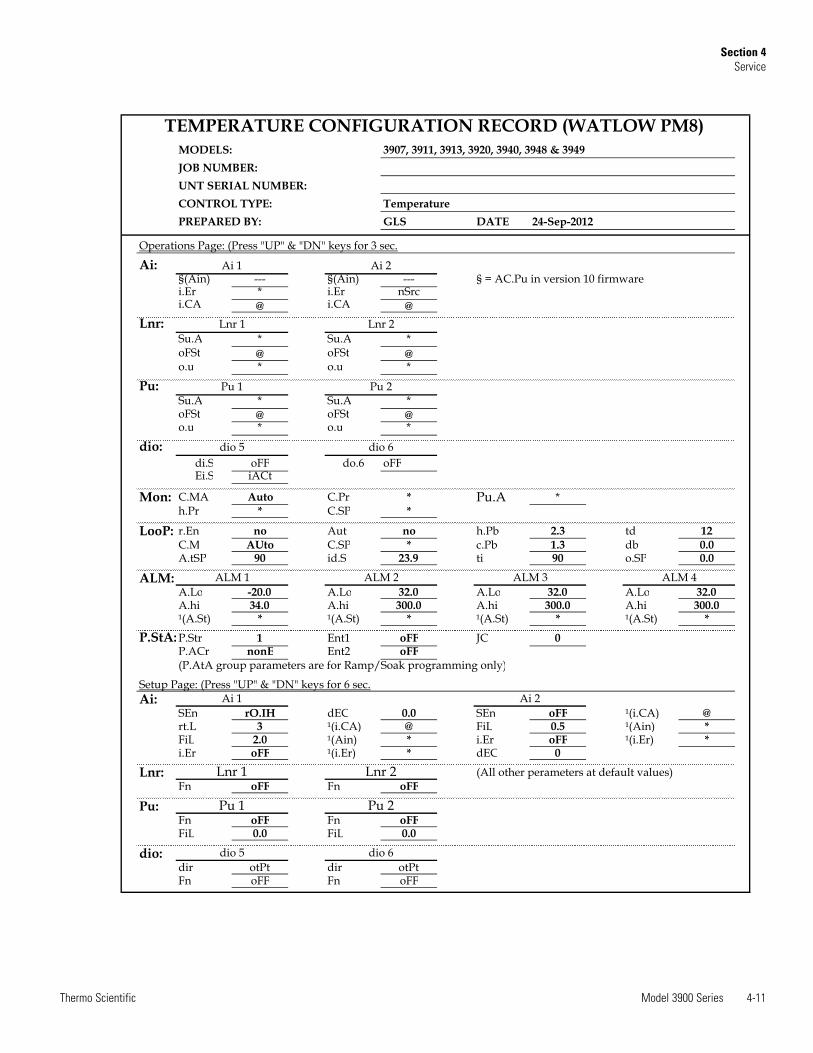
MODELS:JOB NUMBER:UNT SERIAL NUMBER:CONTROL TYPE: TemperaturePREPARED BY: GLS DATE
Operations Page: (Press "UP" & "DN" keys for 3 sec.
Ai:§(Ain) --- §(Ain) ---i.Er * i.Er nSrci.CA @ i.CA @
Lnr:Su.A * Su.A *oFSt @ oFSt @o.u * o.u *
Pu:Su.A * Su.A *oFSt @ oFSt @o.u * o.u *
dio:di.S oFF do.6 oFFEi.S iACt
Mon: C.MA Auto C.Pr * Pu.A *h.Pr * C.SP *
LooP: r.En no Aut no h.Pb 2.3 td 12C.M AUto C.SP * c.Pb 1.3 db 0.0A.tSP 90 id.S 23.9 ti 90 o.SP 0.0
ALM:A.Lo -20.0 A.Lo 32.0 A.Lo 32.0 A.Lo 32.0A.hi 34.0 A.hi 300.0 A.hi 300.0 A.hi 300.0¹(A.St) * ¹(A.St) * ¹(A.St) * ¹(A.St) *
P.StA: P.Str 1 Ent1 oFF JC 0P.ACr nonE Ent2 oFF
Setup Page: (Press "UP" & "DN" keys for 6 sec.Ai:
SEn rO.IH dEC 0.0 SEn oFF ¹(i.CA) @rt.L 3 ¹(i.CA) @ FiL 0.5 ¹(Ain) *FiL 2.0 ¹(Ain) * i.Er oFF ¹(i.Er) *i.Er oFF ¹(i.Er) * dEC 0
Lnr: (All other perameters at default values)Fn oFF Fn oFF
Pu:Fn oFF Fn oFFFiL 0.0 FiL 0.0
dio:dir otPt dir otPtFn oFF Fn oFF
Pu 2
Ai 1
(P.AtA group parameters are for Ramp/Soak programming only)
ALM 3 ALM 4
dio 5 dio 6
Lnr 1 Lnr 2
Lnr 2
ALM 1
Pu 1
24-Sep-2012
Pu 1 Pu 2
Ai 2
ALM 2
TEMPERATURE CONFIGURATION RECORD (WATLOW PM8)3907, 3911, 3913, 3920, 3940, 3948 & 3949
dio 5 dio 6
Ai 1 Ai 2
Lnr 1
§ = AC.Pu in version 10 firmware
4-12 Model 3900 Series Thermo Scientific
Section 4Service
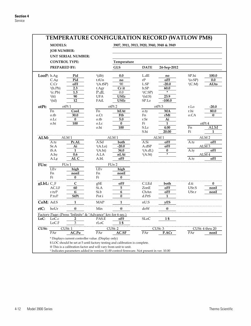
MODELS:JOB NUMBER:UNT SERIAL NUMBER:CONTROL TYPE: TemperaturePREPARED BY: GLS DATE 24-Sep-2012
TEMPERATURE CONFIGURATION RECORD (WATLOW PM8)3907, 3911, 3913, 3920, 3940, 3948 & 3949
LooP: h.Ag Pid ¹(db) 0.0 L.dE no SP.hi 100.0C.Ag Pid t.tUn no rP oFF ¹(o.SP) 0.0C.Cr oFF ¹(A.tSP) 90 L.SP -20.0 ¹(C.M) AUto¹(h.Pb) 2.3 t.Agr Cr it h.SP 60.0¹(c.Pb) 1.3 P.dL 0.0 ¹(C.SP) *¹(ti) 90 UFA USEr ¹(id.S) 23.9¹(td) 12 FAiL USEr SP.Lo -100.0
otPt: r.Lo -20.0Fn CooL Fn hEAt o.ty MA r.hi 80.0o.tb 30.0 o.Ct Ftb Fn rMt o.CA @o.Lo 0 o.tb 5.0 r.Sr Aio.hi 100 o.Lo 0 Fi 1
o.hi 100 S.Lo 4.00 Fn ALMS.hi 20.00 Fi 1
ALM:A.ty Pr.AL A.Sd both A.Si oFF A.ty oFFSr.A Ai ¹(A.Lo) -20.0 A.dSP oFFiS.A 1 ¹(A.hi) 34.0 ¹(A.dL) 0 A.ty oFFA.hy 0.6 A.LA nLAt ¹(A.St) *A.Lg AL C A.bL oFF A.ty oFF
FUn:LEv high LEv highFn nonE Fn nonEFi 0 Fi 0
gLbL: C_F C gSE oFF C.LEd both d.ti 0AC.LF 60 Si.A 5 ZonE oFF USr.S nonEr.tyP ti Si.b 6 ChAn oFF USr.r nonEP.tyP StPt Pot i 0 d.PrS 1
CoM: Ad.S 1 MAP 1 nU.S yES
rtC: hoUr @ Min @ doW @
Factory Page: (Press "Infinity" & "Advance" kry for 6 sec.) LoC: LoC.o 2 PAS.E oFF SLoC 1 $
LoC.P 3 rLoC 1 $CUSt:
PAr AC.Pu PAr AC.SP PAr P.ACr PAr nonE* Displays current controller value. (Display only)$ LOC should be set at 5 until factory testing and calibration is complete.@ This is a calibration factor and will vary from unit to unit.¹ Indicates parameters added in version 11.00 control firmware. Not present in ver. 10.00
CUSt: 4 thru 20CUSt: 1 CUSt: 2 CUSt: 3
ALM 1
otPt 1
otPt 4
ALM 1 ALM 1 ALM 2
FUn 1
otPt 2 otPt 3
ALM 3
ALM 4
FUn 2
Model 3900 Series 4-13Thermo Scientific
Section 4Routine Maintenance
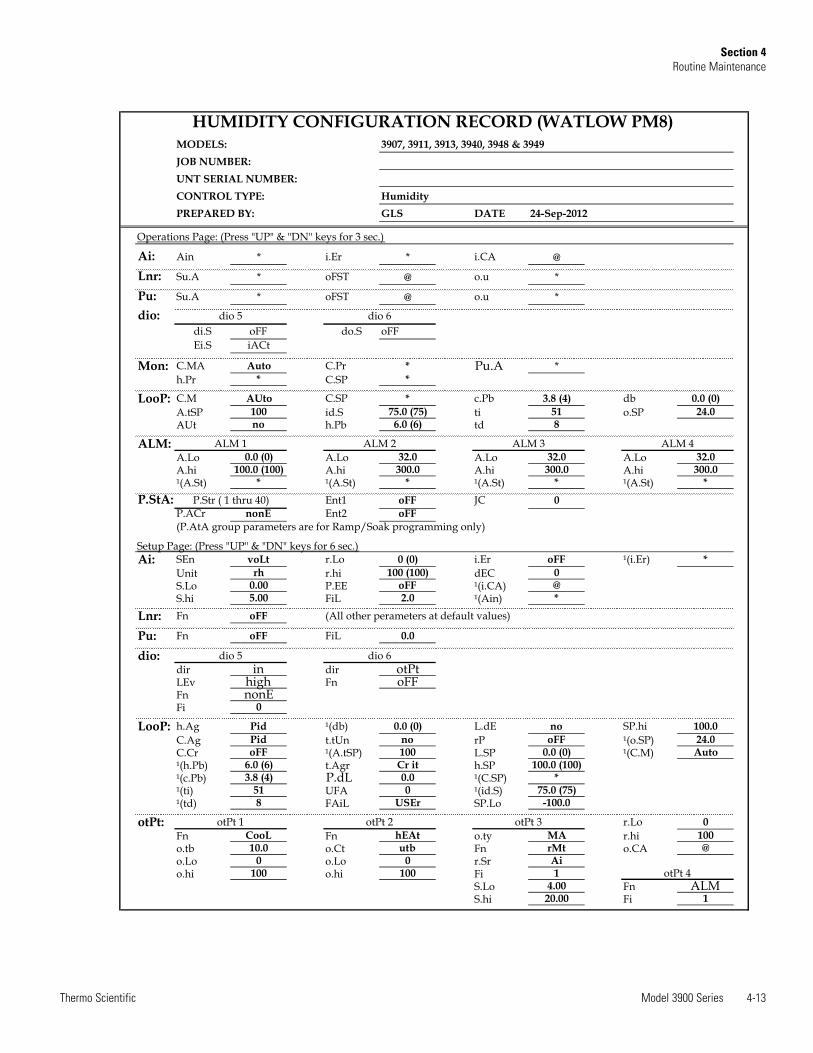
MODELS:JOB NUMBER:UNT SERIAL NUMBER:CONTROL TYPE: HumidityPREPARED BY: GLS DATE
Operations Page: (Press "UP" & "DN" keys for 3 sec.)
Ai: Ain * i.Er * i.CA @
Lnr: Su.A * oFST @ o.u *
Pu: Su.A * oFST @ o.u *
dio:di.S oFF do.S oFFEi.S iACt
Mon: C.MA Auto C.Pr * Pu.A *h.Pr * C.SP *
LooP: C.M AUto C.SP * c.Pb 3.8 (4) db 0.0 (0)A.tSP 100 id.S 75.0 (75) ti 51 o.SP 24.0AUt no h.Pb 6.0 (6) td 8
ALM:A.Lo 0.0 (0) A.Lo 32.0 A.Lo 32.0 A.Lo 32.0A.hi 100.0 (100) A.hi 300.0 A.hi 300.0 A.hi 300.0¹(A.St) * ¹(A.St) * ¹(A.St) * ¹(A.St) *
P.StA: Ent1 oFF JC 0P.ACr nonE Ent2 oFF
Setup Page: (Press "UP" & "DN" keys for 6 sec.)Ai: SEn voLt r.Lo 0 (0) i.Er oFF ¹(i.Er) *
Unit rh r.hi 100 (100) dEC 0S.Lo 0.00 P.EE oFF ¹(i.CA) @S.hi 5.00 FiL 2.0 ¹(Ain) *
Lnr: Fn oFF
Pu: Fn oFF FiL 0.0
dio:dir in dir otPtLEv high Fn oFFFn nonEFi 0
LooP: h.Ag Pid ¹(db) 0.0 (0) L.dE no SP.hi 100.0C.Ag Pid t.tUn no rP oFF ¹(o.SP) 24.0C.Cr oFF ¹(A.tSP) 100 L.SP 0.0 (0) ¹(C.M) Auto¹(h.Pb) 6.0 (6) t.Agr Cr it h.SP 100.0 (100)¹(c.Pb) 3.8 (4) P.dL 0.0 ¹(C.SP) *¹(ti) 51 UFA 0 ¹(id.S) 75.0 (75)¹(td) 8 FAiL USEr SP.Lo -100.0
otPt: r.Lo 0Fn CooL Fn hEAt o.ty MA r.hi 100o.tb 10.0 o.Ct utb Fn rMt o.CA @o.Lo 0 o.Lo 0 r.Sr Aio.hi 100 o.hi 100 Fi 1
S.Lo 4.00 Fn ALMS.hi 20.00 Fi 1
otPt 4
(All other perameters at default values)
dio 5 dio 6
otPt 1 otPt 2
HUMIDITY CONFIGURATION RECORD (WATLOW PM8)3907, 3913, 3940, 3948 & 3949
dio 5 dio 6
24-Sep-2012
otPt 3
ALM 1 ALM 2 ALM 3
P.Str ( 1 thru 40)
(P.AtA group parameters are for Ramp/Soak programming only)
ALM 4
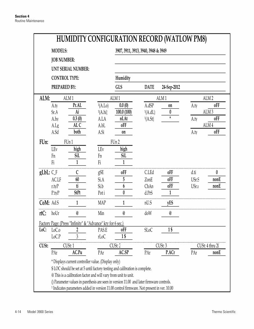
4-14 Model 3900 Series Thermo Scientific
Section 4Routine Maintenance
MODELS:JOB NUMBER:UNT SERIAL NUMBER:CONTROL TYPE: HumidityPREPARED BY: GLS DATE
HUMIDITY CONFIGURATION RECORD (WATLOW PM8)3907, 3913, 3940, 3948 & 3949
24-Sep-2012
ALM:A.ty Pr.AL ¹(A.Lo) 0.0 (0) A.dSP on A.ty oFFSr.A Ai ¹(A.hi) 100.0 (100) ¹(A.dL) 0A.hy 0.3 (0) A.LA nLAt ¹(A.St) * A.ty oFFA.Lg AL C A.bL oFFA.Sd both A.Si on A.ty oFF
FUn:LEv high LEv highFn SiL Fn SiLFi 1 Fi 1
gLbL: C_F C gSE oFF C.LEd oFF d.ti 0AC.LF 60 Si.A 5 ZonE oFF USr.S nonEr.tyP ti Si.b 6 ChAn oFF USr.r nonEP.tyP StPt Pot i 0 d.PrS 1
CoM: Ad.S 1 MAP 1 nU.S yES
rtC: hoUr @ Min @ doW @
Factory Page: (Press "Infinity" & "Advance" kry for 6 sec.) LoC: LoC.o 2 PAS.E oFF SLoC 1 $
LoC.P 3 rLoC 1 $CUSt:
PAr AC.Pu PAr AC.SP PAr P.ACr PAr nonE* Displays current controller value. (Display only)$ LOC should be set at 5 until factory testing and calibration is complete.@ This is a calibration factor and will vary from unit to unit.() Parameter values in parethesis are seen in version 11.00 and later firmware controls.¹ Indicates parameters added in version 11.00 control firmware. Not present in ver. 10.00
ALM 1 ALM 1 ALM 2ALM 1
ALM 3
ALM 4
CUSt: 4 thru 20
FUn 1 FUn 2
CUSt: 1 CUSt: 2 CUSt: 3
Model 3900 Series 4-15Thermo Scientific
Section 4Service
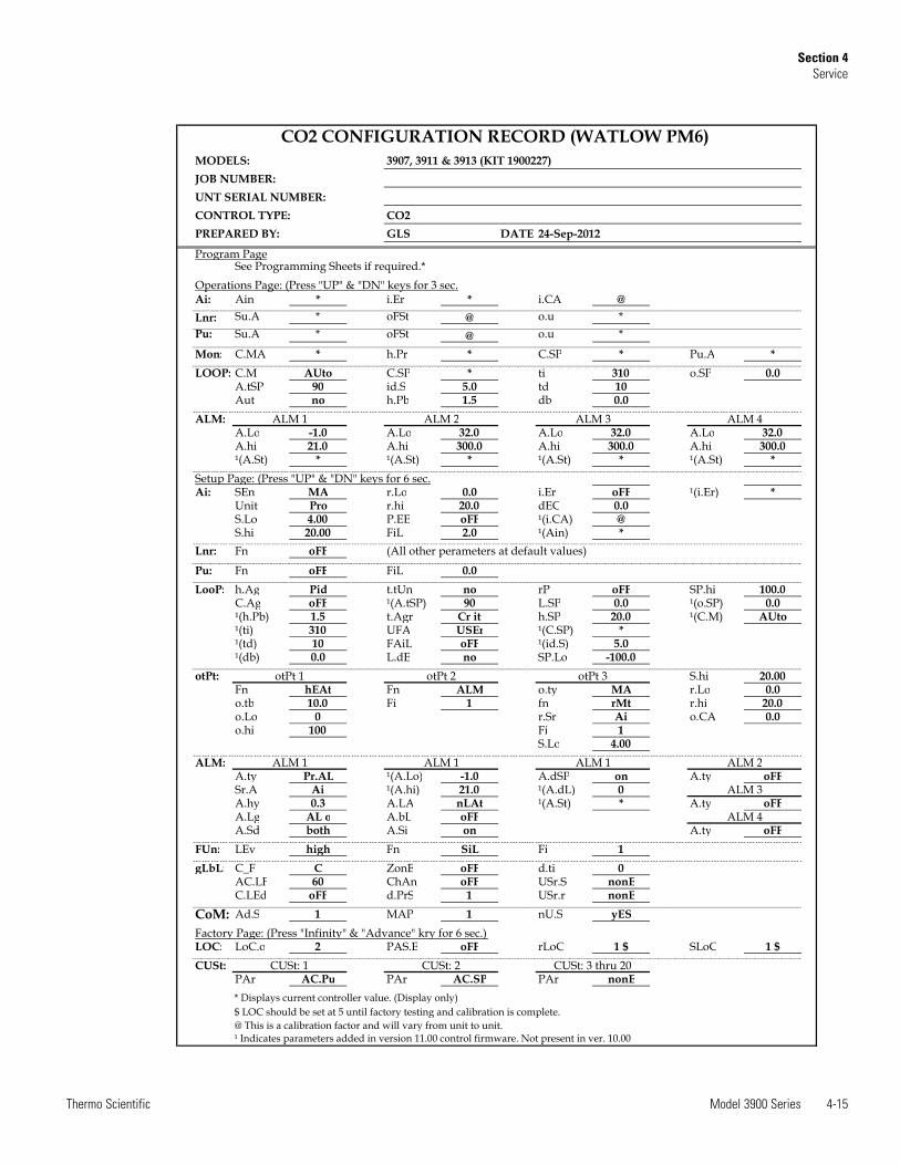
MODELS:JOB NUMBER:UNT SERIAL NUMBER:CONTROL TYPE:PREPARED BY: GLS DATE
Program PageSee Programming Sheets if required.*
Operations Page: (Press "UP" & "DN" keys for 3 sec.Ai: Ain * i.Er * i.CA @Lnr: Su.A * oFSt @ o.u *Pu: Su.A * oFSt @ o.u *
Mon: C.MA * h.Pr * C.SP * Pu.A *LOOP: C.M AUto C.SP * ti 310 o.SP 0.0
A.tSP 90 id.S 5.0 td 10Aut no h.Pb 1.5 db 0.0
ALM:A.Lo -1.0 A.Lo 32.0 A.Lo 32.0 A.Lo 32.0A.hi 21.0 A.hi 300.0 A.hi 300.0 A.hi 300.0¹(A.St) * ¹(A.St) * ¹(A.St) * ¹(A.St) *
Setup Page: (Press "UP" & "DN" keys for 6 sec.Ai: SEn MA r.Lo 0.0 i.Er oFF ¹(i.Er) *
Unit Pro r.hi 20.0 dEC 0.0S.Lo 4.00 P.EE oFF ¹(i.CA) @S.hi 20.00 FiL 2.0 ¹(Ain) *
Lnr: Fn oFF
Pu: Fn oFF FiL 0.0LooP: h.Ag Pid t.tUn no rP oFF SP.hi 100.0
C.Ag oFF ¹(A.tSP) 90 L.SP 0.0 ¹(o.SP) 0.0¹(h.Pb) 1.5 t.Agr Cr it h.SP 20.0 ¹(C.M) AUto¹(ti) 310 UFA USEr ¹(C.SP) *¹(td) 10 FAiL oFF ¹(id.S) 5.0¹(db) 0.0 L.dE no SP.Lo -100.0
otPt: S.hi 20.00Fn hEAt Fn ALM o.ty MA r.Lo 0.0o.tb 10.0 Fi 1 fn rMt r.hi 20.0o.Lo 0 r.Sr Ai o.CA 0.0o.hi 100 Fi 1
S.Lo 4.00ALM:
A.ty Pr.AL ¹(A.Lo) -1.0 A.dSP on A.ty oFFSr.A Ai ¹(A.hi) 21.0 ¹(A.dL) 0A.hy 0.3 A.LA nLAt ¹(A.St) * A.ty oFFA.Lg AL o A.bL oFFA.Sd both A.Si on A.ty oFF
FUn: LEv high Fn SiL Fi 1gLbL: C_F C ZonE oFF d.ti 0
AC.LF 60 ChAn oFF USr.S nonEC.LEd oFF d.PrS 1 USr.r nonE
CoM: Ad.S 1 MAP 1 nU.S yESFactory Page: (Press "Infinity" & "Advance" kry for 6 sec.) LOC: LoC.o 2 PAS.E oFF rLoC 1 $ SLoC 1 $CUSt:
PAr AC.Pu PAr AC.SP PAr nonE* Displays current controller value. (Display only)$ LOC should be set at 5 until factory testing and calibration is complete.@ This is a calibration factor and will vary from unit to unit.¹ Indicates parameters added in version 11.00 control firmware. Not present in ver. 10.00
otPt 1 otPt 2 otPt 3
(All other perameters at default values)
ALM 1
ALM 4
ALM 2 ALM 3 ALM 4
CUSt: 1 CUSt: 2 CUSt: 3 thru 20
ALM 1 ALM 1 ALM 1 ALM 2
ALM 3
CO2 CONFIGURATION RECORD (WATLOW PM6)3907, 3911 & 3913 (KIT 1900227)
CO2 24-Sep-2012
4-16 Model 3900 Series Thermo Scientific
Section 4Service
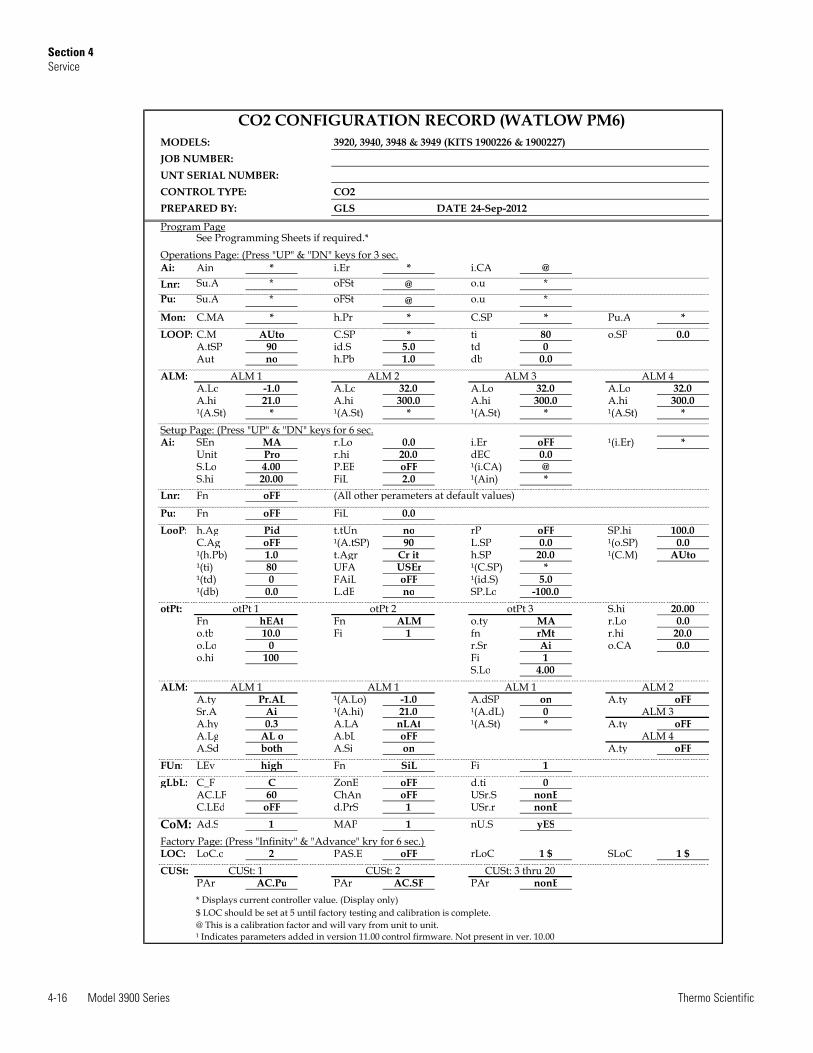
MODELS:JOB NUMBER:UNT SERIAL NUMBER:CONTROL TYPE:PREPARED BY: GLS DATE
Program PageSee Programming Sheets if required.*
Operations Page: (Press "UP" & "DN" keys for 3 sec.Ai: Ain * i.Er * i.CA @Lnr: Su.A * oFSt @ o.u *Pu: Su.A * oFSt @ o.u *
Mon: C.MA * h.Pr * C.SP * Pu.A *LOOP: C.M AUto C.SP * ti 80 o.SP 0.0
A.tSP 90 id.S 5.0 td 0Aut no h.Pb 1.0 db 0.0
ALM:A.Lo -1.0 A.Lo 32.0 A.Lo 32.0 A.Lo 32.0A.hi 21.0 A.hi 300.0 A.hi 300.0 A.hi 300.0¹(A.St) * ¹(A.St) * ¹(A.St) * ¹(A.St) *
Setup Page: (Press "UP" & "DN" keys for 6 sec.Ai: SEn MA r.Lo 0.0 i.Er oFF ¹(i.Er) *
Unit Pro r.hi 20.0 dEC 0.0S.Lo 4.00 P.EE oFF ¹(i.CA) @S.hi 20.00 FiL 2.0 ¹(Ain) *
Lnr: Fn oFF
Pu: Fn oFF FiL 0.0LooP: h.Ag Pid t.tUn no rP oFF SP.hi 100.0
C.Ag oFF ¹(A.tSP) 90 L.SP 0.0 ¹(o.SP) 0.0¹(h.Pb) 1.0 t.Agr Cr it h.SP 20.0 ¹(C.M) AUto¹(ti) 80 UFA USEr ¹(C.SP) *¹(td) 0 FAiL oFF ¹(id.S) 5.0¹(db) 0.0 L.dE no SP.Lo -100.0
otPt: S.hi 20.00Fn hEAt Fn ALM o.ty MA r.Lo 0.0o.tb 10.0 Fi 1 fn rMt r.hi 20.0o.Lo 0 r.Sr Ai o.CA 0.0o.hi 100 Fi 1
S.Lo 4.00ALM:
A.ty Pr.AL ¹(A.Lo) -1.0 A.dSP on A.ty oFFSr.A Ai ¹(A.hi) 21.0 ¹(A.dL) 0A.hy 0.3 A.LA nLAt ¹(A.St) * A.ty oFFA.Lg AL o A.bL oFFA.Sd both A.Si on A.ty oFF
FUn: LEv high Fn SiL Fi 1gLbL: C_F C ZonE oFF d.ti 0
AC.LF 60 ChAn oFF USr.S nonEC.LEd oFF d.PrS 1 USr.r nonE
CoM: Ad.S 1 MAP 1 nU.S yESFactory Page: (Press "Infinity" & "Advance" kry for 6 sec.) LOC: LoC.o 2 PAS.E oFF rLoC 1 $ SLoC 1 $CUSt:
PAr AC.Pu PAr AC.SP PAr nonE* Displays current controller value. (Display only)$ LOC should be set at 5 until factory testing and calibration is complete.@ This is a calibration factor and will vary from unit to unit.¹ Indicates parameters added in version 11.00 control firmware. Not present in ver. 10.00
ALM 4
CUSt: 1 CUSt: 2 CUSt: 3 thru 20
ALM 1 ALM 1 ALM 1 ALM 2
ALM 3
ALM 1 ALM 2 ALM 3 ALM 4
(All other perameters at default values)
otPt 1 otPt 2 otPt 3
CO2 CONFIGURATION RECORD (WATLOW PM6)3920, 3940, 3948 & 3949 (KITS 1900226 & 1900227)
CO2 24-Sep-2012
Model 3900 Series 4-17Thermo Scientific
Section 4Service
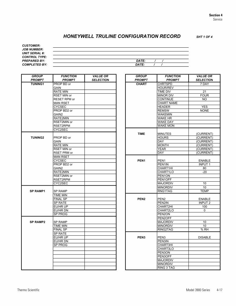
HONEYWELL TRULINE CONFIGURATION RECORD SHT 1 OF 4
CUSTOMER:JOB NUMBER:UNIT SERIAL #:CONTROL TYPE:PREPARED BY: DATE: / /COMPLETED BY: DATE: / /
GROUP FUNCTION VALUE OR GROUP FUNCTION VALUE ORPROMPT PROMPT SELECTION PROMPT PROMPT SELECTIONTUNING1 PROP BD or CHART CHRTSPD 7 DAY
GAIN HOUR/REVRATE MIN TIME DIV 21RSET MIN or MINOR DIV FOURRESET RPM or CONTINUE NOMAN RSET CHART NAMECYCSEC HEADER YESPROP BD2 or REMSW NONEGAIN2 WAKEMINRATE2MIN WAKE HRRSET2MIN or WAKE DAYRSET2RPM WAKE MONCYC2SEC
TIME MINUTES (CURRENT)TUNING2 PROP BD or HOURS (CURRENT)
GAIN DAY (CURRENT)RATE MIN MONTH (CURRENT)RSET MIN or YEAR (CURRENT)RSET PRM or DAY (CURRENT)MAN RSETCYCSEC PEN1 PEN1 ENABLEPROP BD2 or PEN1IN INPUT 1GAIN2 CHART1HI 80RATE2MIN CHART1LO -20RSET2MIN or PEN1ONRSET2RPM PEN1OFFCYC2SEC MAJORDIV 10
MINORDIV 10SP RAMP1 SP RAMP RNG1TAG TEMP
TIME MINFINAL SP PEN2 PEN2 ENABLESP RATE PEN2IN INPUT 2EU/HR UP CHART2HI 100EU/HR DN CHART2LO 0SP PROG PEN2ON
PEN2OFFSP RAMP2 SP RAMP MAJORDIV 10
TIME MIN MINORDIV 10FINAL SP RING2TAG % RHSP RATEEU/HR UP PEN3 PEN3 DISABLEEU/HR DN PEN3INSP PROG CHART3HI
CHART3LOPEN3ONPEN3OFFMAJORDIVMINORDIVRING 3 TAG
4-18 Model 3900 Series Thermo Scientific
Section 4Service
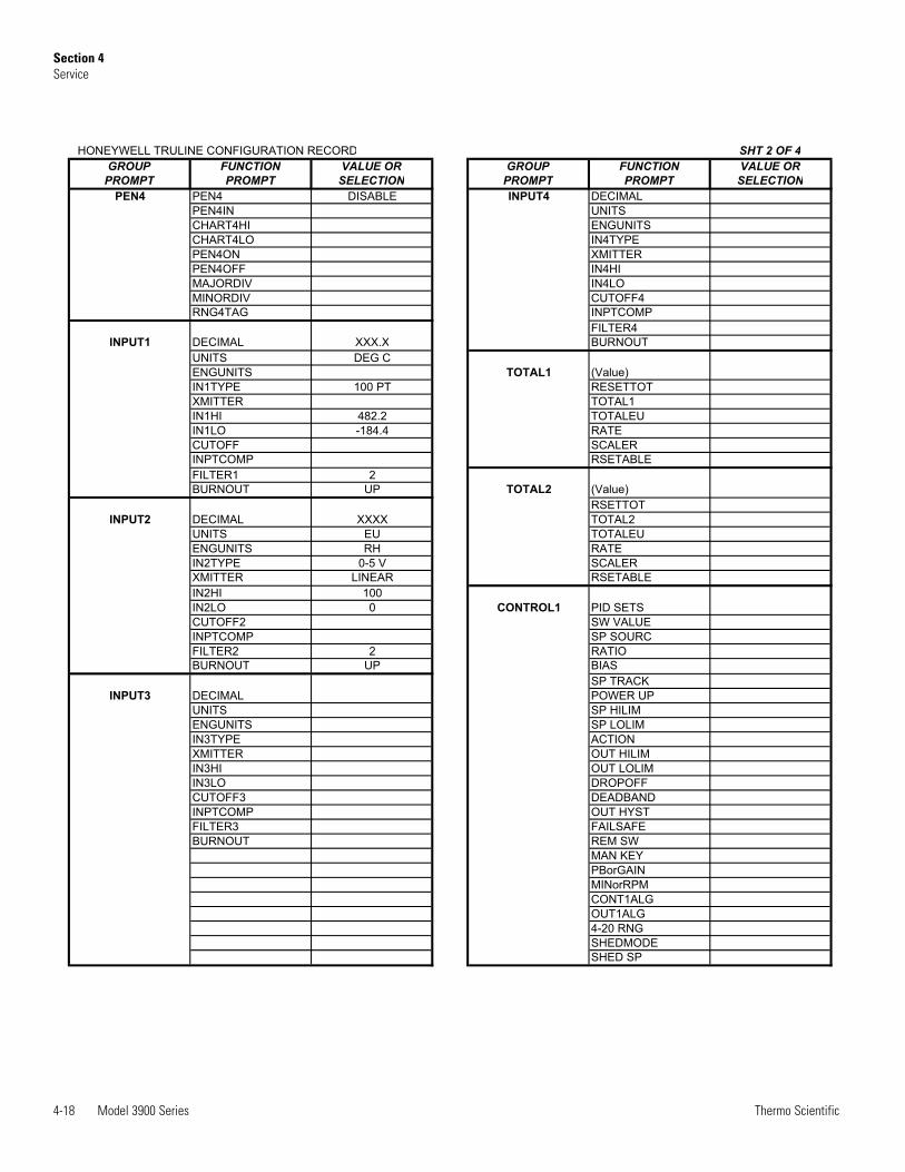
HONEYWELL TRULINE CONFIGURATION RECORD SHT 2 OF 4GROUP FUNCTION VALUE OR GROUP FUNCTION VALUE OR
PROMPT PROMPT SELECTION PROMPT PROMPT SELECTIONPEN4 PEN4 DISABLE INPUT4 DECIMAL
PEN4IN UNITSCHART4HI ENGUNITSCHART4LO IN4TYPEPEN4ON XMITTERPEN4OFF IN4HIMAJORDIV IN4LOMINORDIV CUTOFF4RNG4TAG INPTCOMP
FILTER4INPUT1 DECIMAL XXX.X BURNOUT
UNITS DEG CENGUNITS TOTAL1 (Value)IN1TYPE 100 PT RESETTOTXMITTER TOTAL1IN1HI 482.2 TOTALEUIN1LO -184.4 RATECUTOFF SCALERINPTCOMP RSETABLEFILTER1 2BURNOUT UP TOTAL2 (Value)
RSETTOTINPUT2 DECIMAL XXXX TOTAL2
UNITS EU TOTALEUENGUNITS RH RATEIN2TYPE 0-5 V SCALERXMITTER LINEAR RSETABLEIN2HI 100IN2LO 0 CONTROL1 PID SETSCUTOFF2 SW VALUEINPTCOMP SP SOURCFILTER2 2 RATIOBURNOUT UP BIAS
SP TRACKINPUT3 DECIMAL POWER UP
UNITS SP HILIMENGUNITS SP LOLIMIN3TYPE ACTIONXMITTER OUT HILIMIN3HI OUT LOLIMIN3LO DROPOFFCUTOFF3 DEADBANDINPTCOMP OUT HYSTFILTER3 FAILSAFEBURNOUT REM SW
MAN KEYPBorGAINMINorRPMCONT1ALGOUT1ALG4-20 RNGSHEDMODESHED SP
Model 3900 Series 4-19Thermo Scientific
Section 4Service
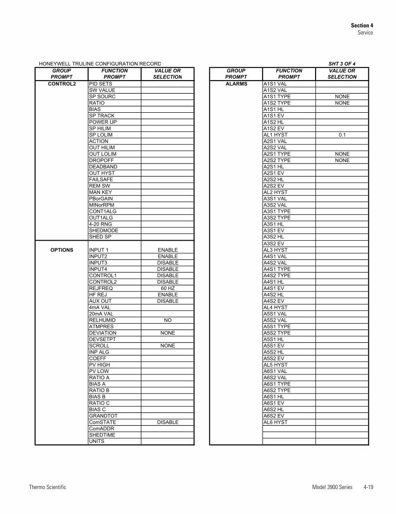
HONEYWELL TRULINE CONFIGURATION RECORD SHT 3 OF 4GROUP FUNCTION VALUE OR GROUP FUNCTION VALUE OR
PROMPT PROMPT SELECTION PROMPT PROMPT SELECTIONCONTROL2 PID SETS ALARMS A1S1 VAL
SW VALUE A1S2 VALSP SOURC A1S1 TYPE NONERATIO A1S2 TYPE NONEBIAS A1S1 HLSP TRACK A1S1 EVPOWER UP A1S2 HLSP HILIM A1S2 EVSP LOLIM AL1 HYST 0.1ACTION A2S1 VALOUT HILIM A2S2 VALOUT LOLIM A2S1 TYPE NONEDROPOFF A2S2 TYPE NONEDEADBAND A2S1 HLOUT HYST A2S1 EVFAILSAFE A2S2 HLREM SW A2S2 EVMAN KEY AL2 HYSTPBorGAIN A3S1 VALMINorRPM A3S2 VALCONT1ALG A3S1 TYPEOUT1ALG A3S2 TYPE4-20 RNG A3S1 HLSHEDMODE A3S1 EVSHED SP A3S2 HL
A3S2 EVOPTIONS INPUT 1 ENABLE AL3 HYST
INPUT2 ENABLE A4S1 VALINPUT3 DISABLE A4S2 VALINPUT4 DISABLE A4S1 TYPECONTROL1 DISABLE A4S2 TYPECONTROL2 DISABLE A4S1 HLREJFREQ 60 HZ A4S1 EVHF REJ ENABLE A4S2 HLAUX OUT DISABLE A4S2 EV4mA VAL AL4 HYST20mA VAL A5S1 VALRELHUMID NO A5S2 VALATMPRES A5S1 TYPEDEVIATION NONE A5S2 TYPEDEVSETPT A5S1 HLSCROLL NONE A5S1 EVINP ALG A5S2 HLCOEFF A5S2 EVPV HIGH AL5 HYSTPV LOW A6S1 VALRATIO A A6S2 VALBIAS A A6S1 TYPERATIO B A6S2 TYPEBIAS B A6S1 HLRATIO C A6S1 EVBIAS C A6S2 HLGRANDTOT A6S2 EVComSTATE DISABLE AL6 HYSTComADDRSHEDTIMEUNITS
4-20 Model 3900 Series Thermo Scientific
Section 4Routine Maintenance
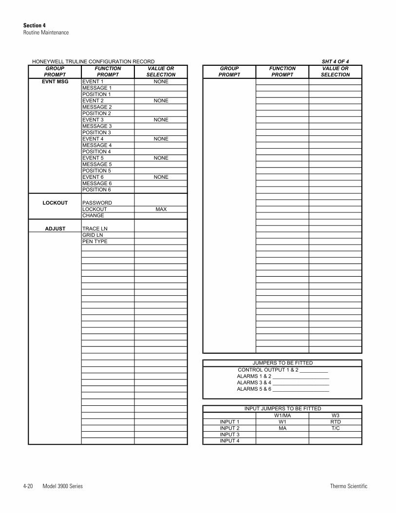
HONEYWELL TRULINE CONFIGURATION RECORD SHT 4 OF 4GROUP FUNCTION VALUE OR GROUP FUNCTION VALUE OR
PROMPT PROMPT SELECTION PROMPT PROMPT SELECTIONEVNT MSG EVENT 1 NONE
MESSAGE 1POSITION 1EVENT 2 NONEMESSAGE 2POSITION 2EVENT 3 NONEMESSAGE 3POSITION 3EVENT 4 NONEMESSAGE 4POSITION 4EVENT 5 NONEMESSAGE 5POSITION 5EVENT 6 NONEMESSAGE 6POSITION 6
LOCKOUT PASSWORDLOCKOUT MAXCHANGE
ADJUST TRACE LNGRID LNPEN TYPE
W1/MA W3INPUT 1 W1 RTDINPUT 2 MA T/CINPUT 3INPUT 4
ALARMS 5 & 6 ____________________
INPUT JUMPERS TO BE FITTED
JUMPERS TO BE FITTEDCONTROL OUTPUT 1 & 2 __________ALARMS 1 & 2 ____________________ALARMS 3 & 4 ____________________
Model 3900 Series 5-1Thermo Scientific
Section 5 Specifications
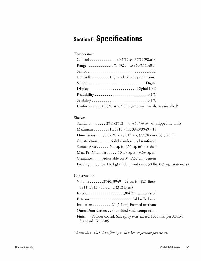
TemperatureControl . . . . . . . . . . . . . .±0.1°C @ +37°C (98.6°F)Range . . . . . . . . . . . . 0°C (32°F) to +60°C (140°F)Sensor . . . . . . . . . . . . . . . . . . . . . . . . . . . . . . .RTDController . . . . . . . . Digital electronic proportionalSetpoint . . . . . . . . . . . . . . . . . . . . . . . . . . . . DigitalDisplay . . . . . . . . . . . . . . . . . . . . . . . . Digital LEDReadability . . . . . . . . . . . . . . . . . . . . . . . . . . .0.1°CSetability . . . . . . . . . . . . . . . . . . . . . . . . . . . . 0.1°CUniformity . . . ±0.3°C at 25°C to 37°C with six shelves installed*
ShelvesStandard . . . . . . . 3911/3913 - 3, 3940/3949 - 6 (shipped w/ unit)Maximum . . . . . . 3911/3913 - 11, 3940/3949 - 19 Dimensions . . . 30.62”W x 25.81”F-B, (77.78 cm x 65.56 cm)Construction . . . . . . .Solid stainless steel reinforcedSurface Area . . . . . . 5.4 sq. ft. (.51 sq. m) per shelfMax. Per Chamber . . . . . 104.3 sq. ft. (9.69 sq. m)Clearance . . . . . Adjustable on 3” (7.62 cm) centers Loading . . .35 lbs. (16 kg) (slide in and out), 50 lbs. (23 kg) (stationary)
ConstructionVolume . . . . . . .3940, 3949 - 29 cu. ft. (821 liters) 3911, 3913 - 11 cu. ft. (312 liters)Interior . . . . . . . . . . . . . . . . . .304 2B stainless steelExterior . . . . . . . . . . . . . . . . . . . . . Cold rolled steelInsulation . . . . . . . . . 2” (5.1cm) Foamed urethaneOuter Door Gasket . . Four sided vinyl compressionFinish . . Powder coated. Salt spray tests exceed 1000 hrs. per ASTM Standard B117-85
* Better than ±0.5°C uniformity at all other temperature parameters.
5-2 Model 3900 Series Thermo Scientific
Section 5Specifications
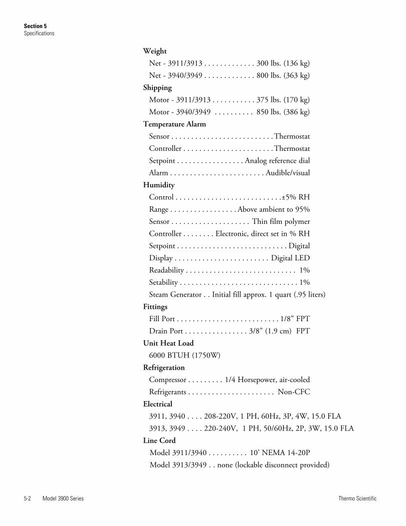
Weight
Net - 3911/3913 . . . . . . . . . . . . . 300 lbs. (136 kg)Net - 3940/3949 . . . . . . . . . . . . . 800 lbs. (363 kg)
Shipping
Motor - 3911/3913 . . . . . . . . . . . 375 lbs. (170 kg)Motor - 3940/3949 . . . . . . . . . . 850 lbs. (386 kg)
Temperature Alarm
Sensor . . . . . . . . . . . . . . . . . . . . . . . . . .ThermostatController . . . . . . . . . . . . . . . . . . . . . . .ThermostatSetpoint . . . . . . . . . . . . . . . . . Analog reference dialAlarm . . . . . . . . . . . . . . . . . . . . . . . . Audible/visual
Humidity
Control . . . . . . . . . . . . . . . . . . . . . . . . . . .±5% RHRange . . . . . . . . . . . . . . . . . Above ambient to 95%Sensor . . . . . . . . . . . . . . . . . . . . Thin film polymerController . . . . . . . . Electronic, direct set in % RHSetpoint . . . . . . . . . . . . . . . . . . . . . . . . . . . . DigitalDisplay . . . . . . . . . . . . . . . . . . . . . . . . Digital LEDReadability . . . . . . . . . . . . . . . . . . . . . . . . . . . . 1%Setability . . . . . . . . . . . . . . . . . . . . . . . . . . . . . . 1%Steam Generator . . Initial fill approx. 1 quart (.95 liters)
Fittings
Fill Port . . . . . . . . . . . . . . . . . . . . . . . . . . 1/8” FPTDrain Port . . . . . . . . . . . . . . . . 3/8” (1.9 cm) FPT
Unit Heat Load
6000 BTUH (1750W)Refrigeration
Compressor . . . . . . . . . 1/4 Horsepower, air-cooledRefrigerants . . . . . . . . . . . . . . . . . . . . . . Non-CFC
Electrical
3911, 3940 . . . . 208-220V, 1 PH, 60Hz, 3P, 4W, 15.0 FLA3913, 3949 . . . . 220-240V, 1 PH, 50/60Hz, 2P, 3W, 15.0 FLA
Line Cord
Model 3911/3940 . . . . . . . . . . 10’ NEMA 14-20PModel 3913/3949 . . none (lockable disconnect provided)
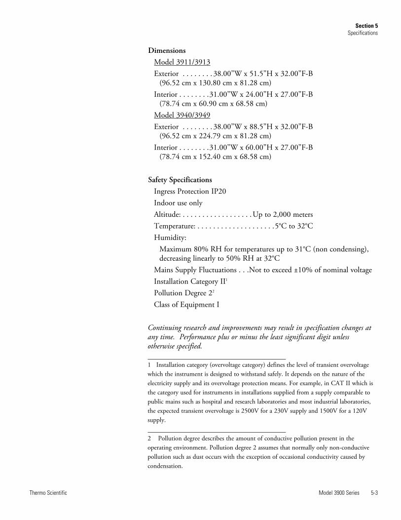
DimensionsModel 3911/3913Exterior . . . . . . . . 38.00”W x 51.5”H x 32.00”F-B (96.52 cm x 130.80 cm x 81.28 cm)Interior . . . . . . . .31.00”W x 24.00”H x 27.00”F-B (78.74 cm x 60.90 cm x 68.58 cm)Model 3940/3949Exterior . . . . . . . . 38.00”W x 88.5”H x 32.00”F-B (96.52 cm x 224.79 cm x 81.28 cm)Interior . . . . . . . .31.00”W x 60.00”H x 27.00”F-B (78.74 cm x 152.40 cm x 68.58 cm)
Safety SpecificationsIngress Protection IP20Indoor use onlyAltitude: . . . . . . . . . . . . . . . . . .Up to 2,000 metersTemperature: . . . . . . . . . . . . . . . . . . . .5°C to 32°CHumidity: Maximum 80% RH for temperatures up to 31°C (non condensing), decreasing linearly to 50% RH at 32°CMains Supply Fluctuations . . .Not to exceed ±10% of nominal voltageInstallation Category II1
Pollution Degree 22
Class of Equipment I
Continuing research and improvements may result in specification changes atany time. Performance plus or minus the least significant digit unlessotherwise specified.
1 Installation category (overvoltage category) defines the level of transient overvoltagewhich the instrument is designed to withstand safely. It depends on the nature of theelectricity supply and its overvoltage protection means. For example, in CAT II which isthe category used for instruments in installations supplied from a supply comparable topublic mains such as hospital and research laboratories and most industrial laboratories,the expected transient overvoltage is 2500V for a 230V supply and 1500V for a 120Vsupply.
2 Pollution degree describes the amount of conductive pollution present in theoperating environment. Pollution degree 2 assumes that normally only non-conductivepollution such as dust occurs with the exception of occasional conductivity caused bycondensation.
Model 3900 Series 5-3Thermo Scientific
Section 5Specifications

Fluorinated Greenhouse Gases
Compliant with REGULATION (EU) No 517/2014 OF THE EUROPEANPARLIAMENT AND OF THE COUNCIL on fluorinated greenhousegases. This product contains foam blown with fluorinated greenhouse gas, R-245fa.
Model 3900 Series 5-4Thermo Scientific
Section 5Service
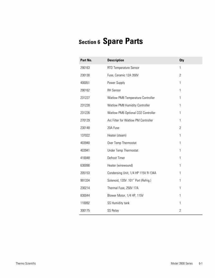
Section 6 Spare Parts
Model 3900 Series 6-1Thermo Scientific
Part No. Description Qty
290163 RTD Temperature Sensor 1
230130 Fuse, Ceramic 12A 350V 2
400051 Power Supply 1
290162 RH Sensor 1
231227 Watlow PM8 Temperature Controller 1
231228 Watlow PM8 Humidity Controller 1
231226 Watlow PM6 Optional CO2 Controller 1
270129 Arc Filter for Watlow PM Controller 1
230148 20A Fuse 2
137022 Heater (steam) 1
403940 Over Temp Thermostat 1
403941 Under Temp Thermostat 1
410048 Defrost Timer 1
630090 Heater (wirewound) 1
205153 Condensing Unit, 1/4 HP 115V R-134A 1
991334 Solenoid, 120V .101” Port (Refrig.) 1
230214 Thermal Fuse, 250V 17A 1
830044 Blower Motor, 1/4 HP, 115V 1
110092 SS Humidity tank 1
300175 SS Relay 2
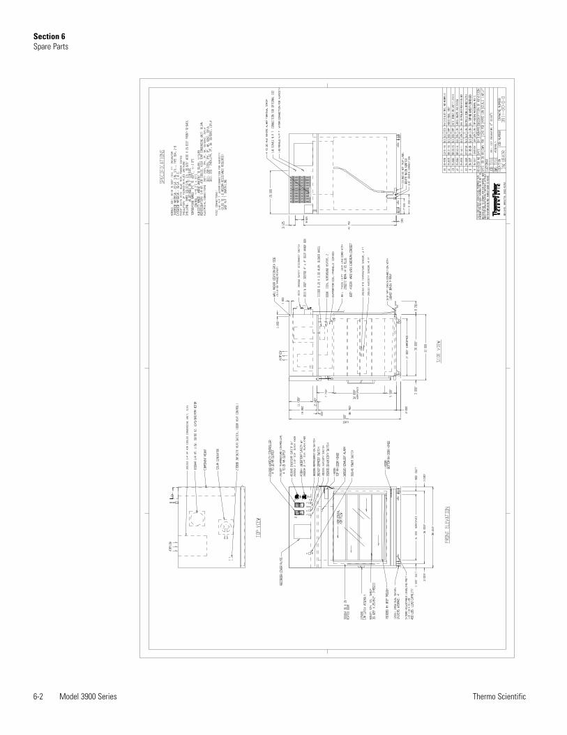
6-2 Model 3900 Series Thermo Scientific
Section 6Spare Parts
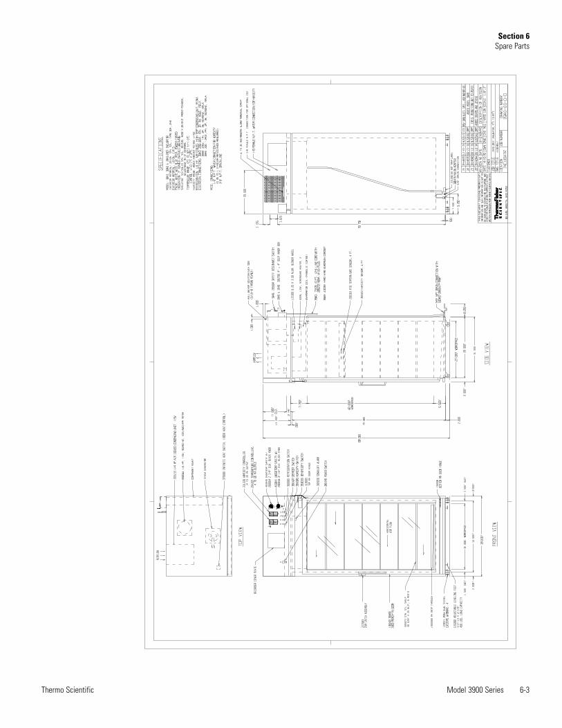
Model 3900 Series 6-3Thermo Scientific
Section 6Spare Parts
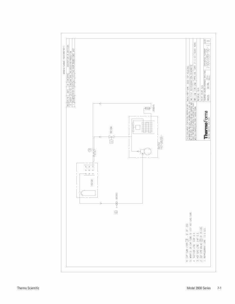
Model 3900 Series 7-1Thermo Scientific
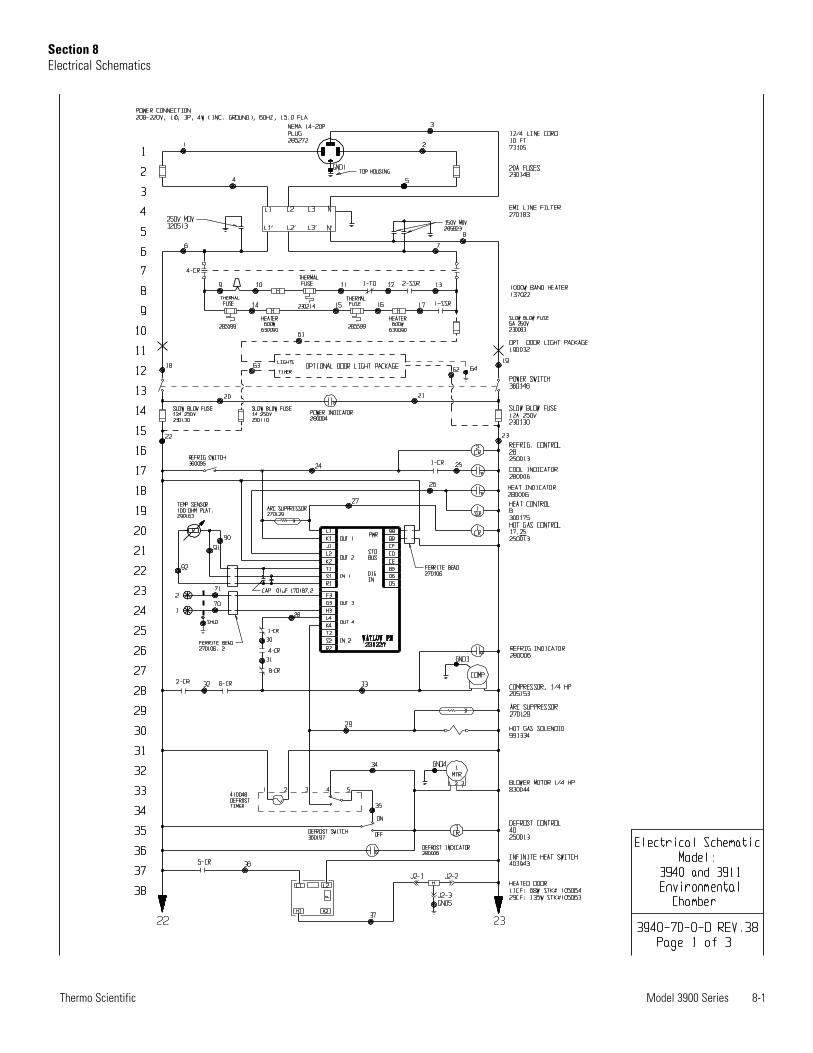
Model 3900 Series 8-1Thermo Scientific
Section 8Electrical Schematics
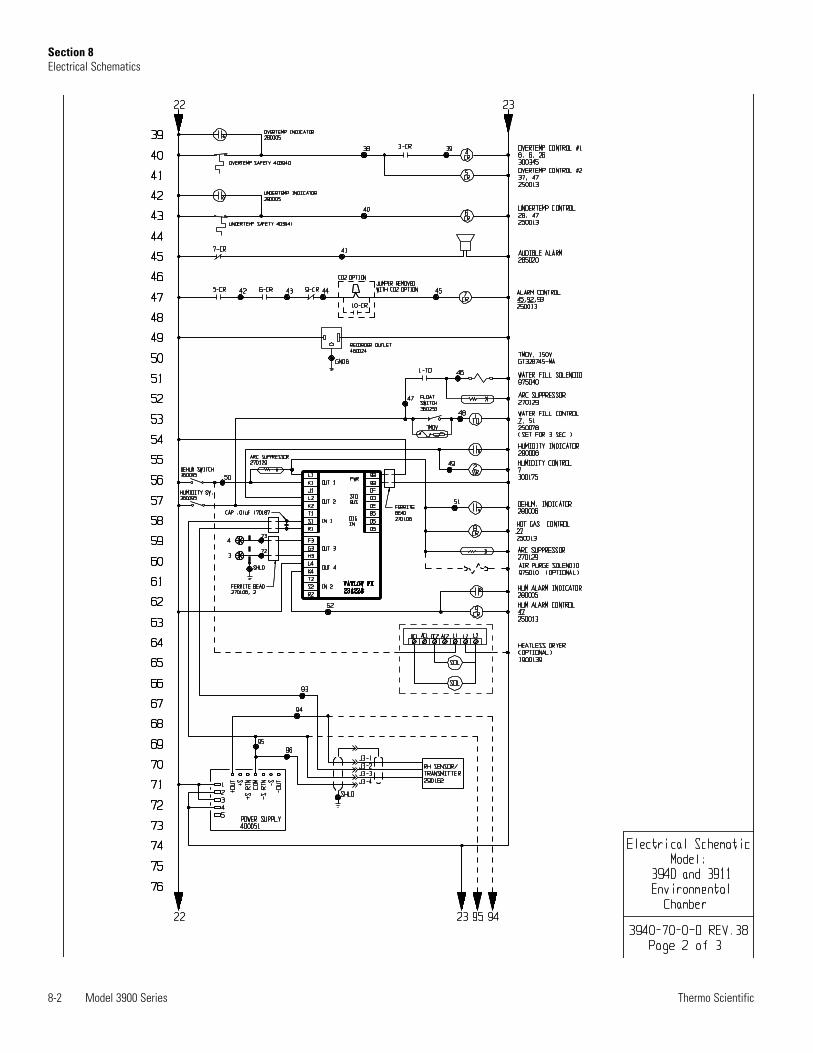
8-2 Model 3900 Series Thermo Scientific
Section 8Electrical Schematics
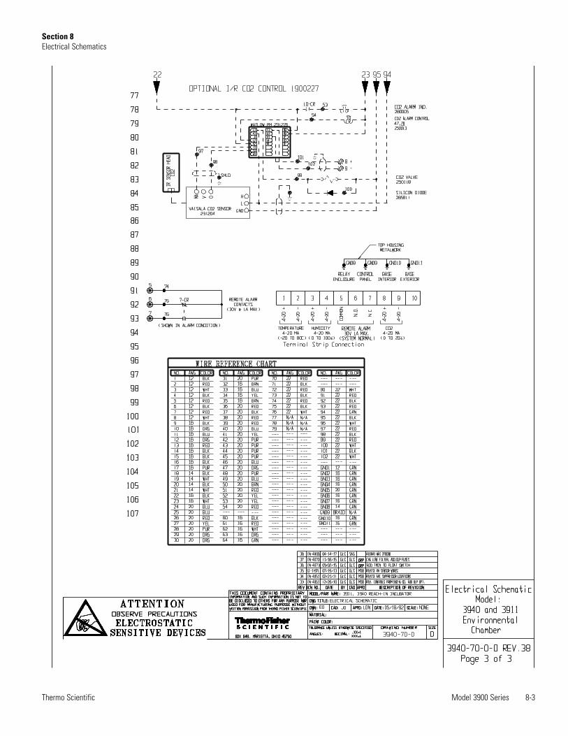
Model 3900 Series 8-3Thermo Scientific
Section 8Electrical Schematics
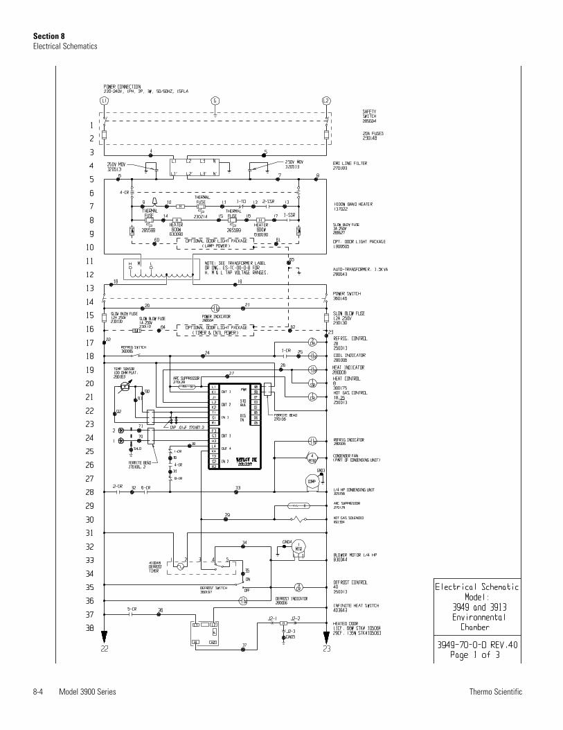
8-4 Model 3900 Series Thermo Scientific
Section 8Electrical Schematics
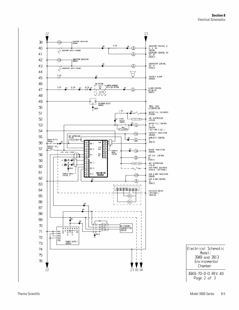
Model 3900 Series 8-5Thermo Scientific
Section 8Electrical Schematics
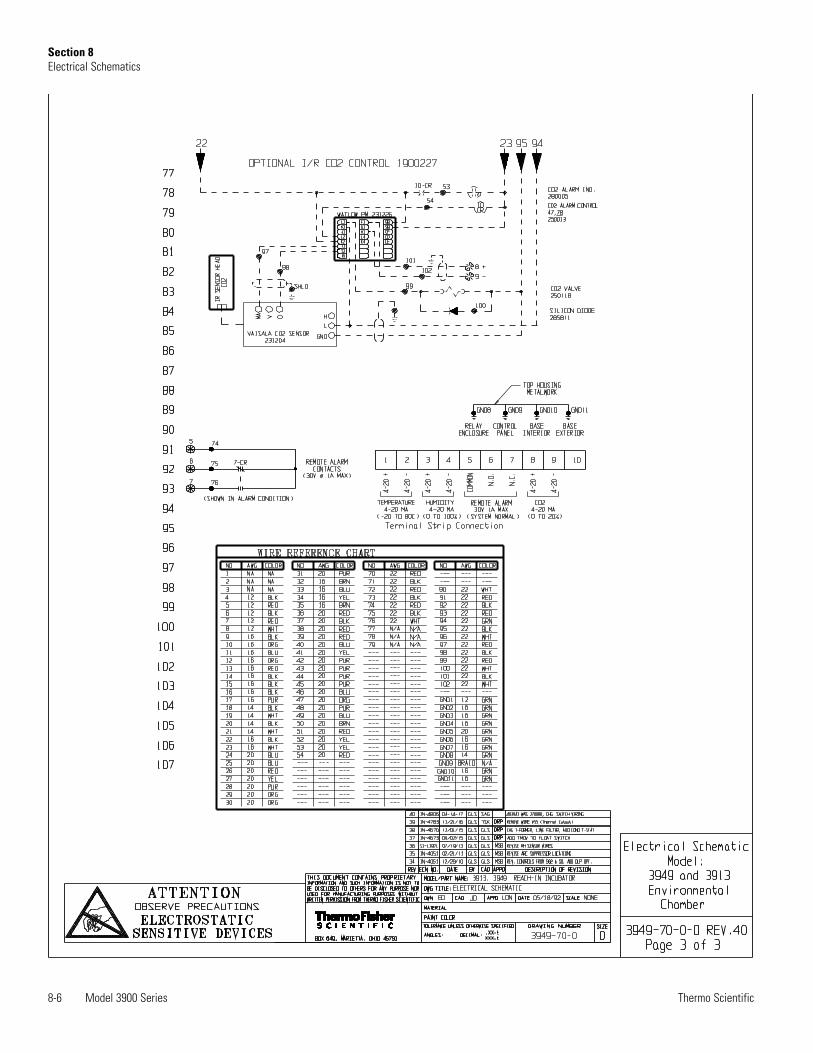
8-6 Model 3900 Series Thermo Scientific
Section 8Electrical Schematics
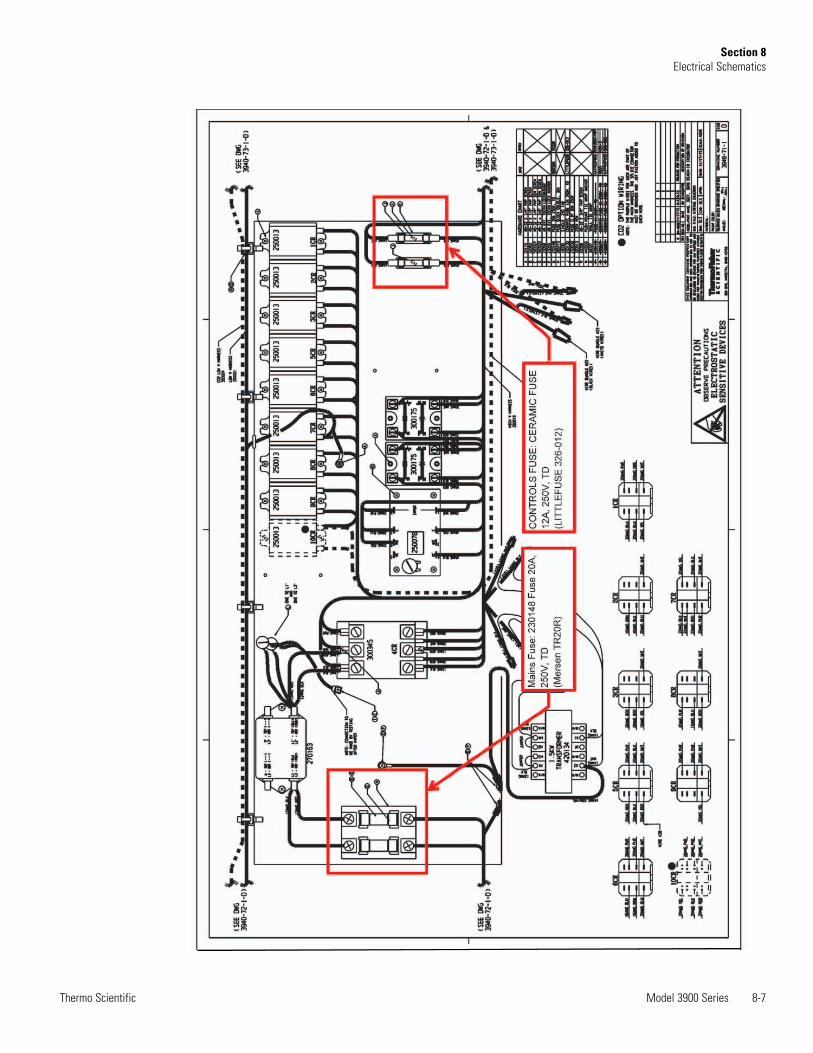
Model 3900 Series 8-7Thermo Scientific
Section 8Electrical Schematics
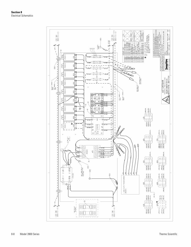
8-8 Model 3900 Series Thermo Scientific
Section 8Electrical Schematics
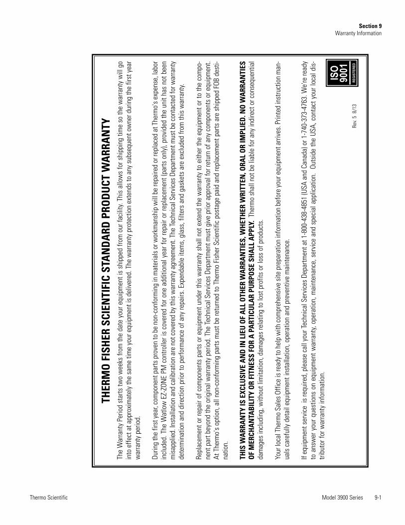
Model 3900 Series 9-1Thermo Scientific
Section 9Warranty Information
THER
MO
FIS
HER
SCI
ENTI
FIC
STA
ND
ARD
PRO
DU
CT W
ARR
AN
TYTh
e W
arra
nty
Perio
d st
arts
two
wee
ks fr
om th
e da
te y
our e
quip
men
t is
ship
ped
from
our
faci
lity.
This
allo
ws
for s
hipp
ing
time
so th
e w
arra
nty
will
go
into
effe
ct a
t app
roxi
mat
ely
the
sam
e tim
e yo
ur e
quip
men
t is
deliv
ered
. The
war
rant
y pr
otec
tion
exte
nds
to a
ny s
ubse
quen
t ow
ner d
urin
g th
e fir
st y
ear
war
rant
y pe
riod.
Durin
g th
e fir
st ye
ar, c
ompo
nent
par
ts p
rove
n to
be
non-
conf
orm
ing
in m
ater
ials
or w
orkm
ansh
ip w
ill b
e re
paire
d or
repl
aced
at T
herm
o's e
xpen
se, l
abor
incl
uded
. The
Wat
low
EZ-
ZON
E PM
con
trolle
r is
cove
red
for o
ne a
dditi
onal
yea
r for
repa
ir or
repl
acem
ent (
parts
onl
y), p
rovi
ded
the
unit
has
not b
een
mis
appl
ied.
Inst
alla
tion
and
calib
ratio
n ar
e no
t cov
ered
by t
his w
arra
nty a
gree
men
t. Th
e Te
chni
cal S
ervi
ces D
epar
tmen
t mus
t be
cont
acte
d fo
r war
rant
yde
term
inat
ion
and
dire
ctio
n pr
ior t
o pe
rform
ance
of a
ny re
pairs
. Exp
enda
ble
item
s, g
lass
, filt
ers
and
gask
ets
are
excl
uded
from
this
war
rant
y.
Repl
acem
ent o
r rep
air o
f com
pone
nts
parts
or e
quip
men
t und
er th
is w
arra
nty
shal
l not
ext
end
the
war
rant
y to
eith
er th
e eq
uipm
ent o
r to
the
com
po-
nent
par
t bey
ond
the
orig
inal
war
rant
y pe
riod.
The
Tech
nica
l Ser
vice
s De
partm
ent m
ust g
ive
prio
r app
rova
l for
retu
rn o
f any
com
pone
nts
or e
quip
men
t.At
The
rmo'
s op
tion,
all
non-
conf
orm
ing
parts
mus
t be
retu
rned
to T
herm
o Fi
sher
Sci
entif
ic p
osta
ge p
aid
and
repl
acem
ent p
arts
are
shi
pped
FOB
des
ti-na
tion.
THIS
WA
RRA
NTY
IS E
XCLU
SIVE
AN
D IN
LIE
U O
F A
LL O
THER
WA
RRA
NTI
ES, W
HET
HER
WRI
TTEN
, ORA
L O
R IM
PLIE
D. N
O W
ARR
AN
TIES
OF
MER
CHA
NTA
BIL
ITY
OR
FITN
ESS
FOR
A P
ART
ICU
LAR
PURP
OSE
SH
ALL
APP
LY.
Ther
mo
shal
l not
be
liabl
e fo
r any
indi
rect
or c
onse
quen
tial
dam
ages
incl
udin
g, w
ithou
t lim
itatio
n, d
amag
es re
latin
g to
lost
pro
fits
or lo
ss o
f pro
duct
s.
Your
loca
l The
rmo
Sale
s Offi
ce is
read
y to
help
with
com
preh
ensi
ve si
te p
repa
ratio
n in
form
atio
n be
fore
your
equ
ipm
ent a
rrive
s. P
rinte
d in
stru
ctio
n m
an-
uals
car
eful
ly d
etai
l equ
ipm
ent i
nsta
llatio
n, o
pera
tion
and
prev
entiv
e m
aint
enan
ce.
If eq
uipm
ent s
ervi
ce i
s re
quire
d, p
leas
e ca
ll yo
ur Te
chni
cal S
ervi
ces
Depa
rtmen
t at 1
-800
-438
-485
1 (U
SA a
nd C
anad
a) o
r 1-7
40-3
73-4
763.
We'
re re
ady
to a
nsw
er y
our q
uest
ions
on
equi
pmen
t war
rant
y, op
erat
ion,
mai
nten
ance
, ser
vice
and
spe
cial
app
licat
ion.
Out
side
the
USA,
con
tact
you
r loc
al d
is-
tribu
tor f
or w
arra
nty
info
rmat
ion.
Rev.
5 8
/13
ISO
9001
REGI
STER
ED
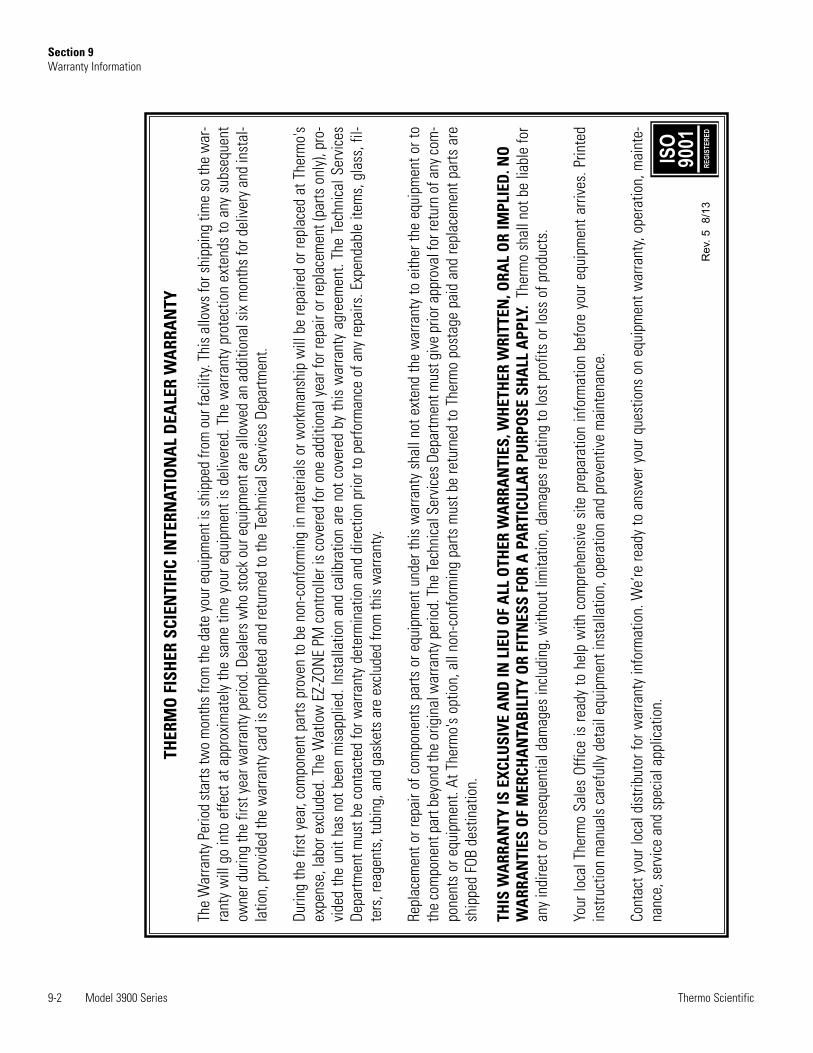
9-2 Model 3900 Series Thermo Scientific
Section 9Warranty Information
THER
MO
FIS
HER
SCI
ENTI
FIC
INTE
RNAT
ION
AL
DEA
LER
WA
RRA
NTY
The
War
rant
y Pe
riod
star
ts tw
o m
onth
s fro
m th
e da
te y
our e
quip
men
t is
ship
ped
from
our
faci
lity.
This
allo
ws
for s
hipp
ing
time
so th
e w
ar-
rant
y w
ill g
o in
to e
ffect
at a
ppro
xim
atel
y th
e sa
me
time
your
equ
ipm
ent i
s de
liver
ed. T
he w
arra
nty
prot
ectio
n ex
tend
s to
any
sub
sequ
ent
owne
r dur
ing
the
first
yea
r war
rant
y pe
riod.
Dea
lers
who
sto
ck o
ur e
quip
men
t are
allo
wed
an
addi
tiona
l six
mon
ths
for d
eliv
ery
and
inst
al-
latio
n, p
rovi
ded
the
war
rant
y ca
rd is
com
plet
ed a
nd re
turn
ed to
the
Tech
nica
l Ser
vice
s De
partm
ent.
Durin
g th
e fir
st y
ear,
com
pone
nt p
arts
pro
ven
to b
e no
n-co
nfor
min
g in
mat
eria
ls o
r wor
kman
ship
will
be
repa
ired
or re
plac
ed a
t The
rmo'
sex
pens
e, la
bor e
xclu
ded.
The
Wat
low
EZ-
ZON
E PM
con
trolle
r is
cove
red
for o
ne a
dditi
onal
yea
r for
repa
ir or
repl
acem
ent (
parts
onl
y), p
ro-
vide
d th
e un
it ha
s no
t bee
n m
isap
plie
d. In
stal
latio
n an
d ca
libra
tion
are
not c
over
ed b
y th
is w
arra
nty
agre
emen
t. Th
e Te
chni
cal S
ervi
ces
Depa
rtmen
t mus
t be
cont
acte
d fo
r war
rant
y de
term
inat
ion
and
dire
ctio
n pr
ior t
o pe
rform
ance
of a
ny re
pairs
. Exp
enda
ble
item
s, g
lass
, fil-
ters
, rea
gent
s, tu
bing
, and
gas
kets
are
exc
lude
d fro
m th
is w
arra
nty.
Repl
acem
ent o
r rep
air o
f com
pone
nts
parts
or e
quip
men
t und
er th
is w
arra
nty
shal
l not
ext
end
the
war
rant
y to
eith
er th
e eq
uipm
ent o
r to
the
com
pone
nt p
art b
eyon
d th
e or
igin
al w
arra
nty p
erio
d. T
he Te
chni
cal S
ervi
ces D
epar
tmen
t mus
t giv
e pr
ior a
ppro
val f
or re
turn
of a
ny co
m-
pone
nts
or e
quip
men
t. At
The
rmo'
s op
tion,
all
non-
conf
orm
ing
parts
mus
t be
retu
rned
to T
herm
o po
stag
e pa
id a
nd re
plac
emen
t par
ts a
resh
ippe
d FO
B de
stin
atio
n.
THIS
WA
RRA
NTY
IS E
XCLU
SIVE
AN
D IN
LIE
U O
F A
LL O
THER
WA
RRA
NTI
ES, W
HET
HER
WRI
TTEN
, ORA
L O
R IM
PLIE
D. N
OW
ARR
AN
TIES
OF
MER
CHA
NTA
BIL
ITY
OR
FITN
ESS
FOR
A P
ART
ICU
LAR
PURP
OSE
SH
ALL
APP
LY.
Ther
mo
shal
l not
be
liabl
e fo
ran
y in
dire
ct o
r con
sequ
entia
l dam
ages
incl
udin
g, w
ithou
t lim
itatio
n, d
amag
es re
latin
g to
lost
pro
fits
or lo
ss o
f pro
duct
s.
Your
loca
l The
rmo
Sale
s Of
fice
is re
ady
to h
elp
with
com
preh
ensi
ve s
ite p
repa
ratio
n in
form
atio
n be
fore
you
r equ
ipm
ent a
rrive
s. P
rinte
din
stru
ctio
n m
anua
ls c
aref
ully
det
ail e
quip
men
t ins
talla
tion,
ope
ratio
n an
d pr
even
tive
mai
nten
ance
.
Cont
act y
our l
ocal
dis
tribu
tor f
or w
arra
nty
info
rmat
ion.
We’
re re
ady
to a
nsw
er y
our q
uest
ions
on
equi
pmen
t war
rant
y, op
erat
ion,
mai
nte-
nanc
e, s
ervi
ce a
nd s
peci
al a
pplic
atio
n.
Rev
. 5 8
/13
ISO
9001
REGI
STER
ED

thermoscientific.com
© 2014 Thermo Fisher Scientific Inc. All rights reserved. All trademarks are the property of Thermo Fisher Scientific and itssubsidiaries. Specifications, termsand pricing are subject to change. Not all products are available in all countries. Please consult your local sales representativefor details.
Thermo Fisher Scientific (Asheville) LLC401 Millcreek RoadMarietta, Ohio 45750
United States
A Thermo Fisher Scientific Brand