Embed Size (px)
Citation preview
This paper is a part of the hereunder thematic dossierpublished in OGST Journal, Vol. 69, No. 5, pp. 773-969
and available online hereCet article fait partie du dossier thématique ci-dessouspublié dans la revue OGST, Vol. 69, n°5, pp. 773-969
et téléchargeable ici
Do s s i e r
DOSSIER Edited by/Sous la direction de : P.-L. Carrette
PART 1Post Combustion CO2 Capture
Captage de CO2 en postcombustionOil & Gas Science and Technology – Rev. IFP Energies nouvelles, Vol. 69 (2014), No. 5, pp. 773-969
Copyright © 2014, IFP Energies nouvelles
773 > Editorial
785 > CO2 Capture Rate Sensitivity Versus Purchase of CO2 Quotas. Optimizing Investment Choicefor Electricity SectorSensibilité du taux de captage de CO2 au prix du quota européen. Usage du faible prix dequota européen de CO2 comme effet de levier pour lancer le déploiement de la technologiede captage en postcombustionP. Coussy and L. Raynal
793 > Emissions to the Atmosphere from Amine-Based Post-Combustion CO2 Capture Plant –Regulatory AspectsÉmissions atmosphériques des installations de captage de CO2 en postcombustion parles amines – Aspects réglementairesM. Azzi, D. Angove, N. Dave, S. Day, T. Do, P. Feron, S. Sharma, M. Attalla andM. Abu Zahra
805 > Formation and Destruction of NDELA in 30 wt% MEA (Monoethanolamine) and 50 wt%DEA (Diethanolamine) SolutionsFormation et destruction de NDELA dans des solutions de 30%m de MEA(monoéthanolamine) et de 50%m de DEA (diéthanolamine)H. Knuutila, N. Asif, S. J. Vevelstad and H. F. Svendsen
821 > Validation of a Liquid Chromatography Tandem Mass Spectrometry Method for TargetedDegradation Compounds of Ethanolamine Used in CO2 Capture: Application to Real SamplesValidation d’une méthode de chromatographie en phase liquide couplée à la spectrométriede masse en tandem pour des composés de dégradation ciblés de l’éthanolamine utiliséedans le captage du CO2 : application à des échantillons réelsV. Cuzuel, J. Brunet, A. Rey, J. Dugay, J. Vial, V. Pichon and P.-L. Carrette
833 > Equilibrium and Transport Properties of Primary, Secondary and Tertiary Aminesby Molecular SimulationPropriétés d’équilibre et de transport d’amines primaires, secondaires et tertiaires parsimulation moléculaireG. A. Orozco, C. Nieto-Draghi, A. D. Mackie and V. Lachet
851 > CO2 Absorption by Biphasic Solvents: Comparison with Lower Phase AloneAbsorption du CO2 par des solvants biphasiques : comparaison avec la phase inférieureisoléeZ. Xu, S. Wang, G. Qi, J. Liu, B. Zhao and C. Chen
865 > Kinetics of Carbon Dioxide with Amines – I. Stopped-Flow Studies in AqueousSolutions. A ReviewCinétique du dioxyde de carbone avec les amines – I. Étude par stopped-flowen solution aqueuse. Une revueG. Couchaux, D. Barth, M. Jacquin, A. Faraj and J. Grandjean
885 > Modeling of the CO2 Absorption in a Wetted Wall Column by Piperazine SolutionsModélisation de l’absorption de CO2 par des solutions de pipérazine dans un filmtombantA. Servia, N. Laloue, J. Grandjean, S. Rode and C. Roizard
903 > Piperazine/N-methylpiperazine/N,N'-dimethylpiperazine as an Aqueous Solvent forCarbon Dioxide CaptureMélange pipérazine/N-méthylpipérazine/N,N’-diméthylpipérazine en solution aqueusepour le captage du CO2S. A. Freeman, X. Chen, T. Nguyen, H. Rafi que, Q. Xu and G. T. Rochelle
915 > Corrosion in CO2 Post-Combustion Capture with Alkanolamines – A ReviewCorrosion dans les procédés utilisant des alcanolamines pour le captage du CO2en postcombustionJ. Kittel and S. Gonzalez
931 > Aqueous Ammonia (NH3) Based Post-Combustion CO2 Capture: A ReviewCapture de CO2 en postcombustion par l’ammoniaque en solution aqueuse (NH3) :synthèseN. Yang, H. Yu, L. Li, D. Xu, W. Han and P. Feron
947 > Enhanced Selectivity of the Separation of CO2 from N2 during Crystallization ofSemi-Clathrates from Quaternary Ammonium SolutionsAmélioration de la sélectivité du captage du CO2 dans les semi-clathrates hydratesen utilisant les ammoniums quaternaires comme promoteurs thermodynamiquesJ.-M. Herri, A. Bouchemoua, M. Kwaterski, P. Brântuas, A. Galfré, B. Bouillot,J. Douzet, Y. Ouabbas and A. Cameirao
969 > ErratumJ. E. Roberts
©Ph
otos:
DOI:10.25
16/og
st/2013201,Fo
tolia/yuliadarling,
IFPE
N,X.
D o s s i e rPost Combustion CO2 Capture
Captage de CO2 en postcombustion
Formation and Destruction of NDELAin 30 wt% MEA (Monoethanolamine)
and 50 wt% DEA (Diethanolamine) Solutions
Hanna Knuutila*, Naveed Asif, Solrun Johanne Vevelstad and Hallvard F. Svendsen
Norwegian University of Science and Technology (NTNU), Department of Chemical Engineering, Sem Saelands vei 4,Trondheim NO 7491 - Norwaye-mail: [email protected]
* Corresponding author
Resume — Formation et destruction de NDELA dans des solutions de 30%m de MEA (monoetha-
nolamine) et de 50%m de DEA (diethanolamine) — La formation de nitrosodiethanolamine
(NDELA) dans une installation pilote de laboratoire a ete etudiee en injectant des quantites
controlees d’oxyde d’azote et de dioxyde d’azote dans le flux de gaz entrant dans l’absorbeur.
La destruction par irradiation UV de la NDELA presente dans le solvant a aussi ete etudiee
sur la meme installation pilote. Deux campagnes de mesure ont ete menees, la premiere
utilisant une solution de 30 %m de monoethanolamine (MEA) et la seconde utilisant une
solution de 50 %m de diethanolamine (DEA). Durant la campagne de mesure sur la DEA, la
destruction de la NDELA dans les eaux de nettoyage a aussi ete testee. De plus, la
degradation thermique d’echantillons de solution degradee preleves dans l’installation pilote a
ete testee. Les resultats indiquent que de la NDELA se forme en presence d’oxyde d’azote et
de dioxyde d’azote. Il a ete constate que la destruction de la NDELA par la lumiere UV dans
la boucle de solvant etait lente. La destruction de la NDELA par la lumiere UV dans le
compartiment des eaux de nettoyage a ete demontree. La degradation de la NDELA durant
des etudes de degradation thermique a 135 �C a ete etablie.
Abstract — Formation and Destruction of NDELA in 30 wt% MEA (Monoethanolamine) and
50 wt% DEA (Diethanolamine) Solutions — The formation of nitrosodiethanolamine (NDELA)
in a lab scale pilot was studied by feeding known amounts of nitrogen oxide and nitrogen dioxide into
the gas entering the absorber. In the same pilot, the destruction by UV-irradiation of NDELA pres-
ent in the solvent was studied. Two campaigns were performed, one with 30 wt% monoethanolamine
(MEA) and one with 50 wt% diethanolamine (DEA). During the DEA campaign the destruction of
NDELA in the water wash section was also tested. Additionally, degraded solution samples with-
drawn from the pilot were tested for thermal degradation. The results show that NDELA was formed
when nitrogen oxide and nitrogen dioxide were present. Destruction of NDELA with UV-light in the
solvent loop was found to be slow. In the water wash section, the UV-light destroyed the NDELA
effectively. NDELA was found to degrade during the thermal degradation studies at 135�C.
Oil & Gas Science and Technology – Rev. IFP Energies nouvelles, Vol. 69 (2014), No. 5, pp. 805-820Copyright � 2013, IFP Energies nouvellesDOI: 10.2516/ogst/2013168
INTRODUCTION
Global warming caused by anthropogenic CO2 emis-
sions is one of the most severe problems presently. Car-
bon capture and storage may offer a route to
significantly reducing these emissions. Of the capture
technologies, reactive absorption seems to be the most
viable option. However, in order to operate absorption
processes on a global scale, one has to make certain that
the processes are benign and do not create additional
environmental problems. One of the issues that could
be detrimental to the application of this technology is
the formation and potential emissions of nitrosamines
when using amines or amino acids as absorption
reagents.
Amine processes have been in use on modest scale for
many years. One of the most used amines, MEA, has
been a popular reagent for capture of CO2 from power
plant exhaust gases, e.g. the Warrior Run plant with
ABB-Lummus technology (Kohl and Nielsen, 1997).
Formation or emissions of nitrosamines from these
plants have not been reported in the open literature.
The formation of nitrosamines from absorption
plants can stem from two sources. One is atmospheric
formation from emissions of solvent amines from the
plant, as discussed by Braten et al. (2008), Wisthaler
(2010) and Nielsen et al. (2010). However, a proper wash
process can limit the emitted exhaust gas amine content
below 0.1 vppm (Graff et al., 2013). Thus this problem
seems to be under control, at least for MEA, and is
not the focus of the present work.
However, nitrosamines may also be formed in the pro-
cess itself. Fostas et al. (2010) found that gas containing
NOx and oxygen led to the formation of levels of
20-50 lg/g of DEA in their AMINOX plant after
25-75 hours. The formation of nitrosamines was also
studied and NDELA (Nitrosodiethanolamine) was the
main product, forming at a rate of 200-700 ng/g after
25-100 hours. The end concentration of NDELA was
0.5 lg/g in the solvent solution. Traces of two volatile
nitrosamines, nitrosodimethylamine (NDMA) and ni-
trosomorpholine (NMOR) were also detected.
Most of the nitrosamines formed in the plant will
most likely stay in the solvent loop, but nitrosamines
have been detected in the gas leaving the water wash sec-
tion located above the absorber (Kolderup et al., 2012).
Even though these measurements were performed in a
research pilot that was not designed to minimize nitrosa-
mine or amine slip, it is reasonable to consider that
nitrosamines would be found in the water wash solutions
also in other plants if they are formed in the solvent
liquid. The volatile nitrosamines will penetrate to the
water wash section in gaseous form, whereas droplets
and aerosols might transfer non-volatile nitrosamines
from the absorber into the water wash.
The formation rate of nitrosamines under normal
operation is not known, but will depend on temperature,
liquid phase composition and the oxygen and NOx con-
tent of the gas phase. NO2 is believed to be the critical
component in NOx and will dissolve in the liquid phase
and may disproportionate into nitrate and nitrite. The
nitrite formed will be reactive toward secondary amine
groups and can form nitrosamines, typically NDELA
(Fostas et al., 2011). This is one possible route to nitro-
samine formation, but there may be others. Direct UV
radiation could be an option to destroy the nitrosamines
in both the solvent and water wash liquids.
Direct UV photolysis is currently used to remove
NDMA from drinking water and treated wastewater and
most of the literature available on destruction of nitrosa-
mines with UV-light is related to water treatment applica-
tions (Sharma, 2012; Nawrocki and Andrzejewski, 2011).
Some literature is available for amine applications.
Jackson and Attala (2012) have a patent on treating an
amine solvent with UV-radiation.
In this paper, the formation and destruction of
NDELA in pilot conditions are studied. The formation
of NDELA is studied by feeding known amounts of
NOandNO2 in the pilot, and the destruction ofNDELA
is studied by irradiating the solvent with UV-light.
Two campaigns were made: one with 30 wt% MEA
and another with 50 wt% DEA. During the DEA cam-
paign the destruction of NDELA in the water wash sec-
tion was also tested. Additionally degraded solution
samples withdrawn from the pilot are tested for thermal
degradation to determine if NDELA degrades at high
temperatures.
1 EXPERIMENTAL APPARATUSES
1.1 UV-Light Reactor
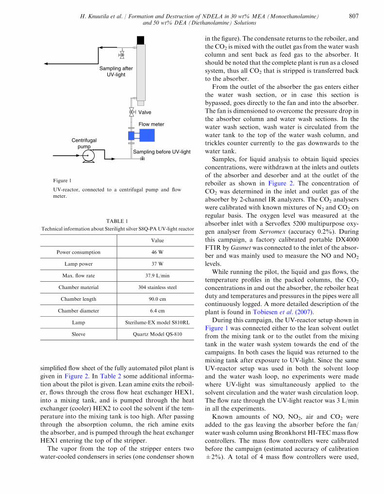
The setup shown in Figure 1 was used to study the
destruction of nitrosamines in the pilot plant. The reac-
tor setup contained a centrifugal circulation pump, a
valve to control the circulation rate, a commercial UV-
light reactor (Sterilight silver S8Q-PA) and sampling
points at the UV-reactor inlet and outlet. Main technical
data of the commercial UV-light reactor with lamp effect
of 37 W are presented in Table 1.
1.2 Lab Scale Pilot Plant
The lab scale pilot plant located at the Gløshaugen cam-
pus in Trondheim was used in the experiments and a
806 Oil & Gas Science and Technology – Rev. IFP Energies nouvelles, Vol. 69 (2014), No. 5
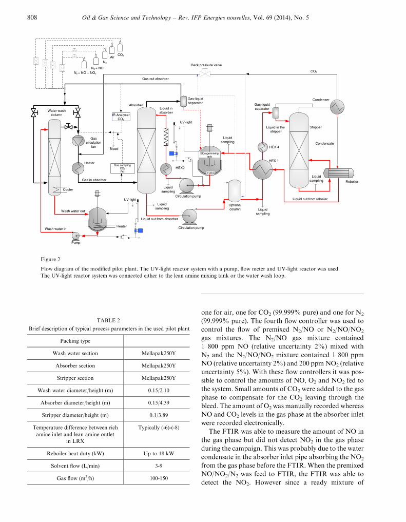
simplified flow sheet of the fully automated pilot plant is
given in Figure 2. In Table 2 some additional informa-
tion about the pilot is given. Lean amine exits the reboil-
er, flows through the cross flow heat exchanger HEX1,
into a mixing tank, and is pumped through the heat
exchanger (cooler) HEX2 to cool the solvent if the tem-
perature into the mixing tank is too high. After passing
through the absorption column, the rich amine exits
the absorber, and is pumped through the heat exchanger
HEX1 entering the top of the stripper.
The vapor from the top of the stripper enters two
water-cooled condensers in series (one condenser shown
in the figure). The condensate returns to the reboiler, and
the CO2 is mixed with the outlet gas from the water wash
column and sent back as feed gas to the absorber. It
should be noted that the complete plant is run as a closed
system, thus all CO2 that is stripped is transferred back
to the absorber.
From the outlet of the absorber the gas enters either
the water wash section, or in case this section is
bypassed, goes directly to the fan and into the absorber.
The fan is dimensioned to overcome the pressure drop in
the absorber column and water wash sections. In the
water wash section, wash water is circulated from the
water tank to the top of the water wash column, and
trickles counter currently to the gas downwards to the
water tank.
Samples, for liquid analysis to obtain liquid species
concentrations, were withdrawn at the inlets and outlets
of the absorber and desorber and at the outlet of the
reboiler as shown in Figure 2. The concentration of
CO2 was determined in the inlet and outlet gas of the
absorber by 2-channel IR analyzers. The CO2 analysers
were calibrated with known mixtures of N2 and CO2 on
regular basis. The oxygen level was measured at the
absorber inlet with a Servoflex 5200 multipurpose oxy-
gen analyser from Servomex (accuracy 0.2%). During
this campaign, a factory calibrated portable DX4000
FTIR by Gasmet was connected to the inlet of the absor-
ber and was mainly used to measure the NO and NO2
levels.
While running the pilot, the liquid and gas flows, the
temperature profiles in the packed columns, the CO2
concentrations in and out the absorber, the reboiler heat
duty and temperatures and pressures in the pipes were all
continuously logged. A more detailed description of the
plant is found in Tobiesen et al. (2007).
During this campaign, the UV-reactor setup shown in
Figure 1 was connected either to the lean solvent outlet
from the mixing tank or to the outlet from the mixing
tank in the water wash system towards the end of the
campaigns. In both cases the liquid was returned to the
mixing tank after exposure to UV-light. Since the same
UV-reactor setup was used in both the solvent loop
and the water wash loop, no experiments were made
where UV-light was simultaneously applied to the
solvent circulation and the water wash circulation loop.
The flow rate through the UV-light reactor was 3 L/min
in all the experiments.
Known amounts of NO, NO2, air and CO2 were
added to the gas leaving the absorber before the fan/
water wash column using Bronkhorst HI-TECmass flow
controllers. The mass flow controllers were calibrated
before the campaign (estimated accuracy of calibration
±2%). A total of 4 mass flow controllers were used,
Flow meter
Valve
Centrifugalpump
Sampling afterUV-light
Sampling before UV-light
Figure 1
UV-reactor, connected to a centrifugal pump and flow
meter.
TABLE 1
Technical information about Sterilight silver S8Q-PAUV-light reactor
Value
Power consumption 46 W
Lamp power 37 W
Max. flow rate 37.9 L/min
Chamber material 304 stainless steel
Chamber length 90.0 cm
Chamber diameter 6.4 cm
Lamp Sterilume-EX model S810RL
Sleeve Quartz Model QS-810
H. Knuutila et al. / Formation and Destruction of NDELA in 30 wt% MEA (Monoethanolamine)and 50 wt% DEA (Diethanolamine) Solutions
807
one for air, one for CO2 (99.999% pure) and one for N2
(99.999% pure). The fourth flow controller was used to
control the flow of premixed N2/NO or N2/NO/NO2
gas mixtures. The N2/NO gas mixture contained
1 800 ppm NO (relative uncertainty 2%) mixed with
N2 and the N2/NO/NO2 mixture contained 1 800 ppm
NO (relative uncertainty 2%) and 200 ppmNO2 (relative
uncertainty 5%). With these flow controllers it was pos-
sible to control the amounts of NO, O2 and NO2 fed to
the system. Small amounts of CO2 were added to the gas
phase to compensate for the CO2 leaving through the
bleed. The amount of O2 was manually recorded whereas
NO and CO2 levels in the gas phase at the absorber inlet
were recorded electronically.
The FTIR was able to measure the amount of NO in
the gas phase but did not detect NO2 in the gas phase
during the campaign. This was probably due to the water
condensate in the absorber inlet pipe absorbing the NO2
from the gas phase before the FTIR. When the premixed
NO/NO2/N2 was feed to FTIR, the FTIR was able to
detect the NO2. However since a ready mixture of
Stripper
Reboiler
HEX 1
Condenser
Liquid in the stripper
Condensate
Absorber
HEX2
Storage/mixingtank
Back pressure valve
Liquid inabsorberWater wash
column
Heater
Gas in absorber
Cooler
Gas samplingCO2
Ftir
IR AnalyserCO2
Gascirculation
fan
Liquidsampling
Liquidsampling
Gas-liquidseparator
Gas-liquidseparator
Bleed HEX 4
CO2
AirCO2
N2
N2 + NON2 + NO + NO2
Gas out absorber
P-210
UV-light
UV-light Liquid out from reboiler
Liquid out from absorber
OptionalcolumnWash water out
Heater Circulation pump
Circulation pump
Liquidsampling
Liquidsampling Liquid
sampling
Pump
Wash water in
Figure 2
Flow diagram of the modified pilot plant. The UV-light reactor system with a pump, flow meter and UV-light reactor was used.
The UV-light reactor system was connected either to the lean amine mixing tank or the water wash loop.
TABLE 2
Brief description of typical process parameters in the used pilot plant
Packing type
Wash water section Mellapak250Y
Absorber section Mellapak250Y
Stripper section Mellapak250Y
Wash water diameter/height (m) 0.15/2.10
Absorber diameter/height (m) 0.15/4.39
Stripper diameter/height (m) 0.1/3.89
Temperature difference between rich
amine inlet and lean amine outlet
in LRX
Typically (-6)-(-8)
Reboiler heat duty (kW) Up to 18 kW
Solvent flow (L/min) 3-9
Gas flow (m3/h) 100-150
808 Oil & Gas Science and Technology – Rev. IFP Energies nouvelles, Vol. 69 (2014), No. 5
N2/NO/NO2 was used together with calibrated flow con-
trollers, it was possible to calculate the amount of NO
and NO2 feed to the system.
1.3 Analytical Methods
The total alkalinity of the solutions was determined by
acid titration (0.1 M H2SO4) and CO2 concentrations
were measured using the BaCl2 method (Ma’mun
et al., 2007). IC was used to measure nitrite, nitrate
and formate with method described in Vevelstad et al.,
(2013) and LC-MS was used to analyse for DEA,
MEA, nitrosamines, HEI, HEF, OZD, HEA, HEPO,
HeGly and BHEOX. Methylamine, dimethylamine, eth-
ylamine, diethylamine and ammonia were analysed
using GC-MS. More thorough descriptions of the
analytical methods for LC-MS and GC-MS can be
found in da Silva et al. (2012) and Lepaumier et al.
(2011).
2 PILOT PLANT EXPERIMENTS
Two pilot campaigns were run, one with 30 wt% MEA
and one with 50 wt% DEA. The main objective of the
campaigns was to study the formation and destruction
of NDELA with NO and NO2 present in the gas phase.
For that reason the goal was to operate the pilot under
stable operating conditions. Both campaigns were
divided into three phases:
– the campaigns started with feeding small amounts of
NO/N2 mixture and O2 to have a NO concentration
around 100 ppm and an O2 level between 5-7 vol%
in the gas entering the absorber;
– after some time, the NO/N2 mixture was switched to a
NO/NO2/N2 mixture. The goal was to keep the NO
level around 100 ppm, which would give NO2 level
of about 11 ppm if the same amount of NO and
NO2 were absorbed. The O2 feeding was continued;
– in the third phase, the feed of all gases was stopped
and the effect of UV-irradiation was measured
in the solvent loop during the campaigns. In the
50 wt% DEA campaign, UV-irradiation was also
tested in the water wash loop.
During the campaigns the solvent degradation and
formation of NDELA was monitored by regular liquid
sampling.
2.1 Pilot Operation During 30 wt% MEA and 50 wt%DEA Campaigns
During both of the campaigns the lean solvent flow rate
was 3 L/min and the gas flow rate was around 120 m3/h.
The pressure in the stripper and reboiler was held around
2 bara. Typical operating conditions during the MEA
and DEA campaigns are presented in Table 3. As seen
from the table for MEA, the rate of stripped and
absorbed CO2 was 5.0 kg/h giving a heat demand of
4.49 kJ/kg. This is in very good agreement with previous
MEA campaigns performed in the same pilot (Tobiesen
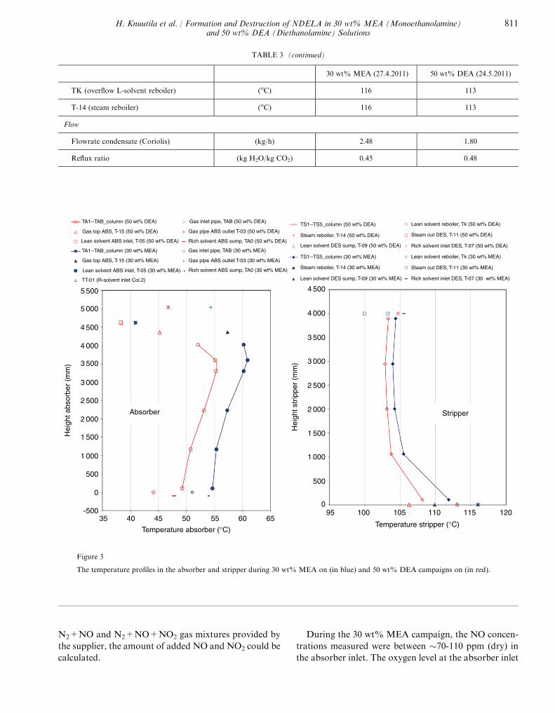
et al., 2008). In Figure 3, the temperature profiles in the
stripper and absorber are presented for the conditions
presented in Table 3. During the MEA campaign, some
adjustments to both reboiler duty (varied from 3 kW to
7 kW) and lean loading were made due to operational
problems. However the data presented in Table 3 gives
a good picture of the operational conditions during the
campaigns. During the DEA campaign, there were no
operational problems.
The 30 wt% MEA solution used in this campaign
was previously used for 700 hours in the same pilot.
During those 700 hours no NO, NO2 or O2 was added
to the system. In the present campaign, 30 wt% MEA
was tested in the lab pilot for 990 hours as shown in
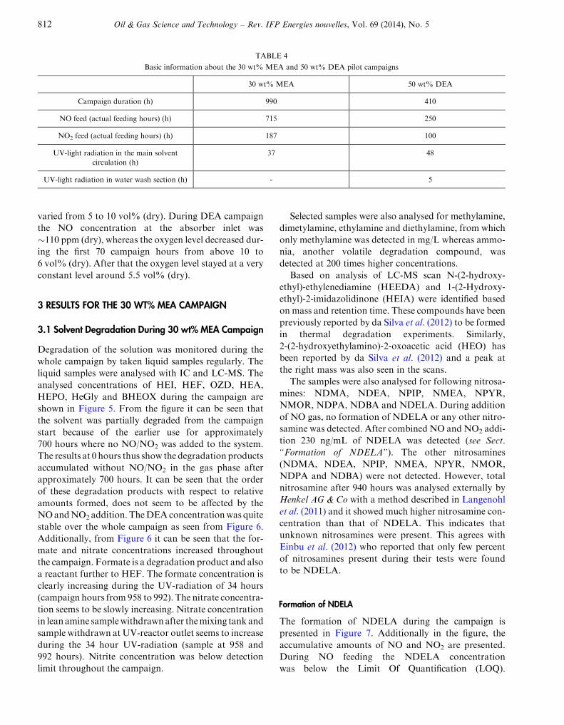
Table 4. During the first 670 hours of the campaign,
only NO and O2 was added to the gas as shown in
Figure 4. During this time, the NO feed was on for
528 hours. Starting from campaign hour 674, a pre-
mixed gas containing both NO and NO2 was fed into
the gas phase until campaign hour 890 as can be seen
in Figure 4. During this time, both NO and NO2 were
fed for 187 hours. The objective of the combined
NO and NO2 feeding was to monitor the formation
of nitrosamines and degradation products. After
890 campaign hours, the NO, NO2, O2 feeds were
stopped and the UV-light reactor was connected to
the lean solvent mixing tank for UV-light tests.
The lab pilot campaign with 50 wt%DEA was similar
to the MEA present campaign where lab pilot was oper-
ated for 990 hours. However, the DEA campaign lasted
only 410 hours. As for the MEA campaign, the DEA
campaign was started by feeding small amounts of the
NO+N2 mixture as well as O2 and CO2 to the gas phase.
After 150 hours of NO+N2 feed, the feed was switched
to a mixture of NO+NO2+N2 as shown in Table 4. The
50 wt% DEA solution was exposed to NO2 for
100 hours. The NO and NO2 feed as a function of
campaign hours is shown in Figure 4b. After the NO
and NO2 feeds were stopped UV-radiation was tested
for NDELA degradation.
The total amount of gas added to the system was
between 1-1.5 L/min and assuming that the system was
completely closed and stable, the added amount would
only leave through the system bleed. Based on the mass
flow controller and the composition of the added
H. Knuutila et al. / Formation and Destruction of NDELA in 30 wt% MEA (Monoethanolamine)and 50 wt% DEA (Diethanolamine) Solutions
809
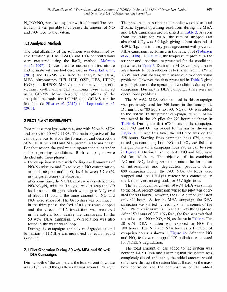
TABLE 3
Typical operational parameters during MEA and DEA campaign
30 wt% MEA (27.4.2011) 50 wt% DEA (24.5.2011)
Absorber
Flow conditioning column
Gas (m3/h) 120 110
Liquid (L/min) 3 3
Superf. velocity inlet ABS (m/s) 1.9 1.8
Gas load (m3/m2, h) 6 800 6 230
Liquid load (m3/m2, h) 10 10
Gas/liquid ratio 666 610
Absorbed CO2 (kg/h) 5.0 4.2
Pressure
P_gas upstream Fl.meter (a) (kPa a) 107 103
Concentration liquid
Amine group (mole MEA/L) 5.6 5.0
Lean loading (mole/mole) 0.35 0.17
Rich loading (mole/mole) 0.45 0.26
Concentration gas
CO2 inlet (vol% dry) 8.2 8.4
CO2 outlet (vol% dry) 5.4 6.0
CO2 inlet (vol% wet) 6.9 7.7
CO2 outlet (vol% wet) 4.6 5.5
Temperature
Gas inlet (oC) 55 49
Gas outlet (oC) 57 45
Liquid inlet (oC) 41 38
Liquid outlet (oC) 54 48
Reboiler
Reboiler duty (kW) 6.8 5.6
Temperature
T-06 (R-solvent downstream EX01) (oC) 109 108
T-07 (R-solvent inlet DES) (oC) 106 105
T-09 (DES, swamp, L-solvent outlet) (oC) 110 106
T-11 (steam out DES) (oC) 103 100
(continued)
810 Oil & Gas Science and Technology – Rev. IFP Energies nouvelles, Vol. 69 (2014), No. 5
N2+NO and N2+NO+NO2 gas mixtures provided by
the supplier, the amount of added NO and NO2 could be
calculated.
During the 30 wt% MEA campaign, the NO concen-
trations measured were between �70-110 ppm (dry) in
the absorber inlet. The oxygen level at the absorber inlet
TABLE 3 (continued)
30 wt% MEA (27.4.2011) 50 wt% DEA (24.5.2011)
TK (overflow L-solvent reboiler) (oC) 116 113
T-14 (steam reboiler) (oC) 116 113
Flow
Flowrate condensate (Coriolis) (kg/h) 2.48 1.80
Reflux ratio (kg H2O/kg CO2) 0.45 0.48
TA1--TAB_column (50 wt% DEA)
Gas top ABS, T-15 (50 wt% DEA)
Gas inlet pipe, TAB (50 wt% DEA)
Gas top ABS, T-15 (30 wt% MEA)
Lean solvent ABS inlet, T-05 (50 wt% DEA)
Lean solvent ABS inlet, T-05 (30 wt% MEA)
TA1--TAB_column (30 wt% MEA)
TT-01 (R-solvent inlet Col.2)
Gas pipe ABS outlet T-03 (50 wt% DEA)
Rich solvent ABS sump, TA0 (50 wt% DEA)
Gas inlet pipe, TAB (30 wt% MEA)
Gas pipe ABS outlet T-03 (30 wt% MEA)
Rich solvent ABS sump, TA0 (30 wt% MEA)
TS1--TS5_column (50 wt% DEA)
Steam reboiler, T-14 (50 wt% DEA)
Lean solvent DES sump, T-09 (50 wt% DEA)
TS1--TS5_column (30 wt% MEA)
Steam reboiler, T-14 (30 wt% MEA)
Lean solvent DES sump, T-09 (30 wt% MEA)
Lean solvent reboiler, Tk (50 wt% DEA)
Steam out DES, T-11 (50 wt% DEA)
Rich solvent inlet DES, T-07 (50 wt% DEA)
Lean solvent reboiler, Tk (30 wt% MEA)
Steam out DES, T-11 (30 wt% MEA)
Rich solvent inlet DES, T-07 (30 wt% MEA)
5 500
5 000
4 500
4 000
3 500
3 000
2 500
2 000
1 500
1 000
500
4 500
4 000
3 500
3 000
2 500
2 000
1 500
1 000
500
0
-50035 40 45 50 55 60 65
Temperature absorber (°C)
095 100 105 110 115 120
Temperature stripper (°C)
StripperAbsorber
Hei
ght a
bsor
ber
(mm
)
Hei
ght s
trip
per
(mm
)
Figure 3
The temperature profiles in the absorber and stripper during 30 wt% MEA on (in blue) and 50 wt% DEA campaigns on (in red).
H. Knuutila et al. / Formation and Destruction of NDELA in 30 wt% MEA (Monoethanolamine)and 50 wt% DEA (Diethanolamine) Solutions
811
varied from 5 to 10 vol% (dry). During DEA campaign
the NO concentration at the absorber inlet was
�110 ppm (dry), whereas the oxygen level decreased dur-
ing the first 70 campaign hours from above 10 to
6 vol% (dry). After that the oxygen level stayed at a very
constant level around 5.5 vol% (dry).
3 RESULTS FOR THE 30 WT% MEA CAMPAIGN
3.1 Solvent Degradation During 30 wt% MEA Campaign
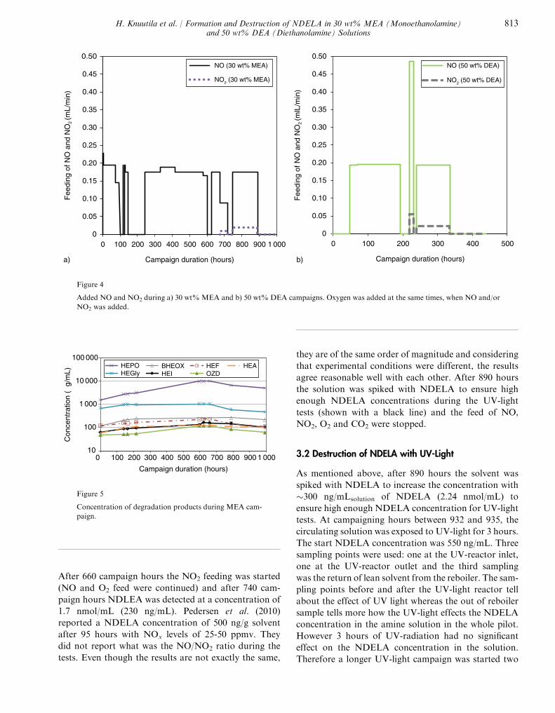
Degradation of the solution was monitored during the
whole campaign by taken liquid samples regularly. The
liquid samples were analysed with IC and LC-MS. The
analysed concentrations of HEI, HEF, OZD, HEA,
HEPO, HeGly and BHEOX during the campaign are
shown in Figure 5. From the figure it can be seen that
the solvent was partially degraded from the campaign
start because of the earlier use for approximately
700 hours where no NO/NO2 was added to the system.
The results at 0 hours thus show the degradation products
accumulated without NO/NO2 in the gas phase after
approximately 700 hours. It can be seen that the order
of these degradation products with respect to relative
amounts formed, does not seem to be affected by the
NOandNO2 addition. TheDEAconcentrationwas quite
stable over the whole campaign as seen from Figure 6.
Additionally, from Figure 6 it can be seen that the for-
mate and nitrate concentrations increased throughout
the campaign. Formate is a degradation product and also
a reactant further to HEF. The formate concentration is
clearly increasing during the UV-radiation of 34 hours
(campaign hours from 958 to 992). The nitrate concentra-
tion seems to be slowly increasing. Nitrate concentration
in lean amine samplewithdrawnafter themixing tank and
sample withdrawn at UV-reactor outlet seems to increase
during the 34 hour UV-radiation (sample at 958 and
992 hours). Nitrite concentration was below detection
limit throughout the campaign.
Selected samples were also analysed for methylamine,
dimetylamine, ethylamine and diethylamine, from which
only methylamine was detected in mg/L whereas ammo-
nia, another volatile degradation compound, was
detected at 200 times higher concentrations.
Based on analysis of LC-MS scan N-(2-hydroxy-
ethyl)-ethylenediamine (HEEDA) and 1-(2-Hydroxy-
ethyl)-2-imidazolidinone (HEIA) were identified based
on mass and retention time. These compounds have been
previously reported by da Silva et al. (2012) to be formed
in thermal degradation experiments. Similarly,
2-(2-hydroxyethylamino)-2-oxoacetic acid (HEO) has
been reported by da Silva et al. (2012) and a peak at
the right mass was also seen in the scans.
The samples were also analysed for following nitrosa-
mines: NDMA, NDEA, NPIP, NMEA, NPYR,
NMOR, NDPA, NDBA and NDELA. During addition
of NO gas, no formation of NDELA or any other nitro-
samine was detected. After combined NO and NO2 addi-
tion 230 ng/mL of NDELA was detected (see Sect.
“Formation of NDELA”). The other nitrosamines
(NDMA, NDEA, NPIP, NMEA, NPYR, NMOR,
NDPA and NDBA) were not detected. However, total
nitrosamine after 940 hours was analysed externally by
Henkel AG & Co with a method described in Langenohl
et al. (2011) and it showed much higher nitrosamine con-
centration than that of NDELA. This indicates that
unknown nitrosamines were present. This agrees with
Einbu et al. (2012) who reported that only few percent
of nitrosamines present during their tests were found
to be NDELA.
Formation of NDELA
The formation of NDELA during the campaign is
presented in Figure 7. Additionally in the figure, the
accumulative amounts of NO and NO2 are presented.
During NO feeding the NDELA concentration
was below the Limit Of Quantification (LOQ).
TABLE 4
Basic information about the 30 wt% MEA and 50 wt% DEA pilot campaigns
30 wt% MEA 50 wt% DEA
Campaign duration (h) 990 410
NO feed (actual feeding hours) (h) 715 250
NO2 feed (actual feeding hours) (h) 187 100
UV-light radiation in the main solvent
circulation (h)
37 48
UV-light radiation in water wash section (h) - 5
812 Oil & Gas Science and Technology – Rev. IFP Energies nouvelles, Vol. 69 (2014), No. 5
After 660 campaign hours the NO2 feeding was started
(NO and O2 feed were continued) and after 740 cam-
paign hours NDLEA was detected at a concentration of
1.7 nmol/mL (230 ng/mL). Pedersen et al. (2010)
reported a NDELA concentration of 500 ng/g solvent
after 95 hours with NOx levels of 25-50 ppmv. They
did not report what was the NO/NO2 ratio during the
tests. Even though the results are not exactly the same,
they are of the same order of magnitude and considering
that experimental conditions were different, the results
agree reasonable well with each other. After 890 hours
the solution was spiked with NDELA to ensure high
enough NDELA concentrations during the UV-light
tests (shown with a black line) and the feed of NO,
NO2, O2 and CO2 were stopped.
3.2 Destruction of NDELA with UV-Light
As mentioned above, after 890 hours the solvent was
spiked with NDELA to increase the concentration with
�300 ng/mLsolution of NDELA (2.24 nmol/mL) to
ensure high enough NDELA concentration for UV-light
tests. At campaigning hours between 932 and 935, the
circulating solution was exposed to UV-light for 3 hours.
The start NDELA concentration was 550 ng/mL. Three
sampling points were used: one at the UV-reactor inlet,
one at the UV-reactor outlet and the third sampling
was the return of lean solvent from the reboiler. The sam-
pling points before and after the UV-light reactor tell
about the effect of UV light whereas the out of reboiler
sample tells more how the UV-light effects the NDELA
concentration in the amine solution in the whole pilot.
However 3 hours of UV-radiation had no significant
effect on the NDELA concentration in the solution.
Therefore a longer UV-light campaign was started two
0
0.05
0.10
0.15
0.20
0.25
0.30
0.35
0.40
0.45
0.50
0 100 200 300 400 500 600 700 800 900 1 000
Fee
ding
of N
O a
nd N
O2 (m
L/m
in)
Campaign duration (hours)
NO (30 wt% MEA)
NO2 (30 wt% MEA)
0
0.05
0.10
0.15
0.20
0.25
0.30
0.35
0.40
0.45
0.50
0 100 200 300 400 500
Fee
ding
of N
O a
nd N
O2 (m
lL/m
in)
Campaign duration (hours)
NO (50 wt% DEA)
NO2 (50 wt% DEA)
a) b)
Figure 4
Added NO and NO2 during a) 30 wt% MEA and b) 50 wt% DEA campaigns. Oxygen was added at the same times, when NO and/or
NO2 was added.
10
100
1 000
10 000
100 000
0 100 200 300 400 500 600 700 800 900 1 000
Con
cent
ratio
n (µ
g/m
L)
Campaign duration (hours)
HEPOHEGly
BHEOXHEI
HEFOZD
HEA
Figure 5
Concentration of degradation products during MEA cam-
paign.
H. Knuutila et al. / Formation and Destruction of NDELA in 30 wt% MEA (Monoethanolamine)and 50 wt% DEA (Diethanolamine) Solutions
813
days later. This time the UV-light was on for 34 hours
and from Figure 8, it can be seen that the concentration
of NDELA decreased approximately 10%. Additionally
it can be seen from the results that the NDELA concen-
tration after the UV-light reactor is very close to the
NDELA concentration entering the UV-light. This indi-
cates that the UV radiation was not very effective. Inter-
esting point here is also that at the start of the first UV
campaign the NDELA concentration was 550 ng/mL
where as two days later the concentration was
640-660 ng/mL. However NO and NO2 feed to the sys-
tem was turned off two day before both of these tests.
This indicated that the reactions towards NDELA con-
tinued after feeding of NO and NO2 is stopped. One final
remark is that the first samples (956 hours) for the long
term UV-radiation tests should be equal. The analytical
results vary from 639 to 659 ng/mL which are within 3%.
This value indicates a good analytical accuracy.
During the long term radiation the destruction of
NDELA seems to be 0-order reaction. The solvent in
the pilot campaign was coloured and had a low penetra-
tion depth throughout the campaign (below 0.5 cm). The
low penetration depth can also explain why short time
irradiation of UV-light did not degrade NDELA signif-
icantly. The short penetration depth can explain why we
see 0-order reaction. NDELA had a limited access to
UV-light and the light was absorbed by other compo-
nents in the solution. This is in line with results from
Knuutila et al. (2012) with fresh and used MEA solu-
tions, where 1st order reaction behaviour was seen in
fresh solutions but where coloured solutions would exhi-
bit 0th-order behaviour. In Knuutila et al. (2012), the
total liquid amount was �30 L, where in the pilot plant
there is around 180 L of solvent. In this paper and in
Knuutila et al. (2012), the same UV-reactor and same
liquid flow was used. So during the pilot campaign the
solvent passed the UV-reactor once an hour (since also
the solvent circulation rate was 3 L/min) whereas in
the batch scale experiments presented in Knuutila et al.
(2012) the 30 wt% MEA passed the UV-reactor every
10 minutes. This difference can also explain some of
the difference in the degradation rates between
Knuutila et al. (2012) and this work.
0
0.5
1.0
1.5
2.0
2.5
3.0
3.5
4.0
4.5
5.0
0 100 200 300 400 500 600 700 800 900 1 000
Con
cnet
ratio
n (m
mol
/L)
Campaign hour
Start of UV-light irradiation experimentsNitrate, lean amineFormate, leann amineDEA, lean amine
Figure 6
Concentration of DEA, formate and nitrate during 30 wt%
MEA campaign.The measurement at campaign hour 932,
is a lean solvent after first 3 hours of UV-irradiation; the
sample at campaign hour 958 is taken just before starting
the second UV-irradiation and the sample at campaign
hour 992 is taken after 34 hours of UV-radiation.
0
0.5
1.0
1.5
2.0
2.5
3.0
3.5
4.0
4.5
5.0
0
50
100
150
200
250
300
350
0 100 200 300 400 500 600 700 800 9001 000
Am
ount
of N
DE
LA in
the
liqui
d ph
ase
(nm
ol/m
L)
Cum
ulat
ive
NO
X a
nd N
O2
feed
to th
e pi
lot (
mol
)
Campaign duration (hours)
Accumulated NOx addedAccumulated NO2 addedSolution spicked with~2.24 nmol/mL NDELA
NDELA concentrationLOQ of NDELAStart of UV-irradiation
Figure 7
Cumulative NO and NO2 feed together with NDELA con-
centration during the 30 wt%MEA campaign. For the first
660 hours, the concentration of NOx is only NO since no
NO2 is added.
500
520
540
560
580
600
620
640
660
680
955 965 975 985 995
ND
ELA
(ng
/mL)
Campaign hours
UV-reactor outletUV-reactor inlet/Lean amine into absorberLean solvent returning from reboilerUV-light turned on
Figure 8
NDELA concentration during the 34 h UV-radiation.
814 Oil & Gas Science and Technology – Rev. IFP Energies nouvelles, Vol. 69 (2014), No. 5
In the literature, nitrite andnitrate has been reported to
be formedduring decompositionofNDMA(Plumlee and
Reinhard, 2007; Lee et al., 2005). In this work, the
amount of degraded NDELA during the 34 hour
UV-light campaign was 0.59 nmol/mL (from 639 ng/
mL to 560 ng/mL). Even if all this amount would give
nitrate, the 0.59 nmol/mL is too small to be seen in the
nitrate concentration shown in Figure 6, when compering
to the increase in nitrate seen throughout the campaign.
4 PILOT TESTS WITH 50 WT% DEA
4.1 Solvent Degradation During 50 wt% DEA Campaign
During the DEA campaign, some liquid samples were
analysed for degradation products using LC-MS. The
results are shown in Figure 9. The concentration of
NDELA is also shown in Figure 9. The decrease in the
NDELA concentration from 70 to 22 lg/mL from 337
to 385 hours is due to the UV-radiation, which will be
discussed more detailed in the next chapter. From the
figure, it can be seen that NDELA is the most common
degradation compound from those that were analysed
followed by HEPO, HEGly and BHEOX. NDELA
was below LOQ (50 ng/mL) before the campaign, but
already after 150 hours, the concentration was
24 lg/mL. The samples were also analyzed for other
nitrosamines (NDMA, NDEA, NPIP, NMEA, NYPR,
NMOR, NDPA and NDBA) but all concentrations were
below the detection limit. Formate was below LOQ in all
samples analysed. Nitrate was detected only in the sam-
ple taken after UV-light campaign (after 385 campaign
hours). HEI was below limit of quantification
(LOQ= 1 lg/mL) until 150 hours. OZD and HEF were
below LOQ (LOQ = 1 lg/mL) until 337 hours.
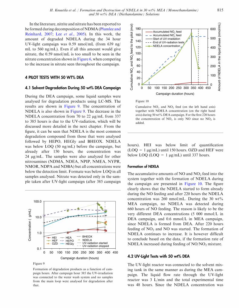
Formation of NDELA
The accumulative amounts of NO and NO2 feed into the
system together with the formation of NDELA during
the campaign are presented in Figure 10. The figure
clearly shows that the NDELA started to form already
during the NO feeding and after 220 hours the NDELA
concentration was 260 nmol/mL. During the 30 wt%
MEA campaign, no NDELA was detected during
660 hours of NO feeding. The reason is likely to be the
very different DEA concentrations (5 000 mmol/L in
DEA campaign, and 0.6 mmol/L in MEA campaign,
since NDELA is formed from DEA. After 220 hours
feeding of NO2 and NO was started. The formation of
NDELA continues to increase. It is however difficult
to conclude based on the data, if the formation rate of
NDELA increased during feeding of NO/NO2 mixture.
4.2 UV-Light Tests with 50 wt% DEA
The UV-light reactor was connected to the solvent mix-
ing tank in the same manner as during the MEA cam-
paign. The liquid flow rate through the UV-light
reactor was 3 L/min and the total experimental time
was 48 hours. Since the NDELA concentration was
0.1
1.0
10.0
100.0
0 50 100 150 200 250 300 350 400 450
Con
cent
ratio
n (µ
g/m
L)
Campaign duration (hours)
HEIHEFOZD
HEAHEPOHEGly
BHEOXNDELAUV-radiation startedUV-radiation stopped
Figure 9
Formation of degradation products as a function of cam-
paign hours. After campaign hour 385 the UV-irradiation
was connected to the water wash system and no samples
from the main loop were analysed for degradation after
that.
0
100
200
300
400
500
600
0
20
40
60
80
100
120
140
160
180
0 50 100 150 200 250 300 350 400 450
Am
ount
of N
DE
LA in
the
liqui
d ph
ase
(nm
ol/m
L)
Cum
ulat
ive
NO
x and
NO
2 fe
ed to
the
pilo
t (m
ol)
Campaign duration (hours)
Accumulated NO2 feedAccumulated NOx feedStart of UV-irradiationEnd of UV-radiation testsNDELA concentration
Figure 10
Cumulative NOx and NO2 feed (on the left hand axis)
together with NDELA concentration (on the right hand
axis) during 50 wt%DEA campaign. For the first 220 hours
the concentration of NOx is only NO since no NO2 is
added.
H. Knuutila et al. / Formation and Destruction of NDELA in 30 wt% MEA (Monoethanolamine)and 50 wt% DEA (Diethanolamine) Solutions
815
not known before starting the UV-light tests, the solu-
tion was spiked with NDELA. The concentration that
would have been reached with the spiked NDELA was
estimated to �0.3 lg/mL. After the first UV-light cam-
paign, the NDELA concentrations for the whole cam-
paign were analysed and it was found that the starting
concentration was 70 lg/mL from which 0.3 lg/mL
was spiked NDELA. The decomposition of NDELA
during theUV-radiation campaign is shown in Figure 11.
During 48 hours approximately 70% of the NDELA
was decomposed. This is much faster than with MEA.
The penetration depth of the 50 wt% DEA solution
was below 0.5 cm and very close to that of 30 wt%
MEA during the MEA campaign. However visual com-
parison of the MEA and DEA solution showed a colour
difference, with 30 wt% MEA being much darker col-
our. Maybe, the fact that the NDELA concentration
during the DEA campaign was more than 10 times
higher, could be part of the explanation, why degrada-
tion of NDELA was faster in DEA solution.
Before UV-light was started no nitrite or nitrate were
detected with IC analyses. After the UV-light campaign
in the lean amine sample 0.43 mmol/L of nitrate was
detected. This value is very close to the limit of quantifica-
tion and samples taken from other parts of the pilot were
below LOQ. During the UV-light campaign and concen-
tration of NDELA decreased from 74 to 22.5 lg/mL
which corresponds to 0.4 mmol/L, which is close to the
value of nitrate found in the solution. It could be specu-
lated if this detected nitrate is due to the decomposition
of NDELA into nitrate. Nitrate and nitrite have been
reported in literature to be formed under NDMA photo-
degradation in weakly acidic water solution (Plumlee and
Reinhard, 2007). However literature findings also suggest
that in alkaline solutions, other inorganic nitrogen
products than nitrate and nitrite like N2 and N2O are
formed (Xu et al., 2009a; Stefan and Bolton, 2002).
During the pilot campaigns, the penetration depth for
both of the amine solutions was low, and even during
50 wt% DEA campaign which was started with fresh
50 wt% DEA the penetration depth was around
0.5 cm after 180 hours of running. The low penetration
depth can explain the slow degradation of NDELA in
the DEA solution. The results are similar to those
reported in Knuutila et al. (2012) where the 50 wt%
DEA was tested in a batch reactor was tested and the
decomposition of NDELA was found to be slow.
UV-Light in the Water Wash Circulation
The effect of UV-light in the water wash section was tested
at the end of DEA campaign. One day before the experi-
ment thewaterwashsectionwas spikedwitha small amount
of DEA and NDELA solution to ensure an NDELA
concentration that could be detected by LC-MS and also
to have DEA concentration representative of what can be
expected in a water wash, about 0.5 wt%. The UV-light
was connected to a mixing tank as shown in Figure 2 and
the liquid flow through the UV-light reactor was approxi-
mately 3 L/min. The total amount of liquid in the water
wash section is approximately 35 L.
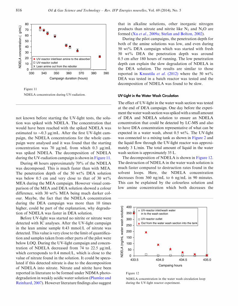
The decomposition of NDELA is shown in Figure 12.
The destruction of NDELA in the water wash solution is
much faster compared to destruction rates found in the
solvent loops. Here, the NDELA concentration
decreases from 360 ng/mL to 6 ng/mL in 90 minutes.
This can be explained by the colourless solution and
low amine concentration which both decreases the
0
50
100
150
200
250
300
350
400
433.5 434.0 434.5 435.0
ND
ELA
(ng
/mL
wat
er w
ash
solu
tion)
Campaing hours
UV-reactor inlet/wash waterin to the wash section
UV-reactor outlet
Out from the water wash section into the tank
Figure 12
NDELA concentration in the water wash circulation loop
during the UV-light reactor experiment.
0
10
20
30
40
50
60
70
80
330 340 350 360 370 380 390
ND
ELA
con
cent
ratio
n (µ
g/m
L)
Campaign duration (hours)
UV-reactor inlet/lean amine to the absorberUV-reactor outletLean amine out from the reboiler
Figure 11
NDELA concentration during UV-radiation.
816 Oil & Gas Science and Technology – Rev. IFP Energies nouvelles, Vol. 69 (2014), No. 5
penetration depth and thereby also the effect of the
UV-light (Knuutila et al., 2012). From the results with
UV-irradiation, one can see that when the solution goes
through the UV-light reactor, almost all the NDELA is
decomposed during one pass through. Additionally the
destruction seems to be 1st order in respect to NDELA.
These results clearly indicate that the use of UV-light is
much more efficient in the water wash section compared
to the solvent loop.
5 THERMAL DEGRADATION OF NDELA
Pilot solutions after the 30 wt% MEA and 50% DEA
campaigns were tested for thermal degradation. Thermal
degradation metal cylinders (316 stainless steel tubes)
were used. The cylinders were filled with the end solu-
tions from 30 wt% MEA and 50 wt% DEA and closed
in a glove box under a nitrogen atmosphere. For each
experiment 10 cylinders were prepared. To check for
leakages, the cylinders including solution were weighed
before and after the experiment.
The cylinders were stored in a thermostatic chamber
at an upright position at 135�C and were not moved or
agitated until sampled. Every week, 2 cylinders with
30 wt% MEA and 50 wt% DEA were sampled. The
solution was analysed to determine the degradation of
NDELA, MEA and DEA and the concentration of
nitrate, nitrite, formate, HEA, HEI, HEPO, OZD,
HEF, BHEOX and HeGly. The total experimental time
was 5 weeks. Cylinders opened for sampling were not
returned to the chamber. Parallel cylinders removed
from the thermostatic chamber day 21 and 35 were both
analysed. From other samplings days only one cylinder
was send to analyses.
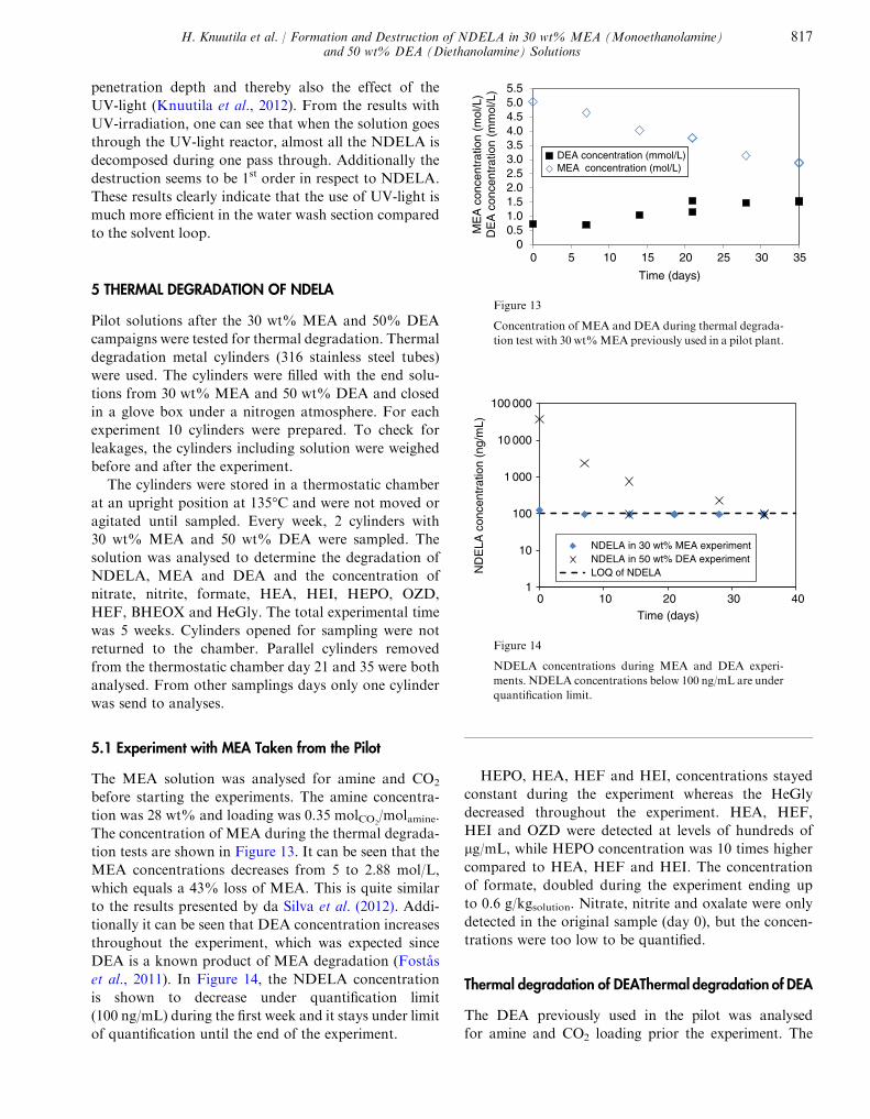
5.1 Experiment with MEA Taken from the Pilot
The MEA solution was analysed for amine and CO2
before starting the experiments. The amine concentra-
tion was 28 wt% and loading was 0.35 molCO2/molamine.
The concentration of MEA during the thermal degrada-
tion tests are shown in Figure 13. It can be seen that the
MEA concentrations decreases from 5 to 2.88 mol/L,
which equals a 43% loss of MEA. This is quite similar
to the results presented by da Silva et al. (2012). Addi-
tionally it can be seen that DEA concentration increases
throughout the experiment, which was expected since
DEA is a known product of MEA degradation (Fostas
et al., 2011). In Figure 14, the NDELA concentration
is shown to decrease under quantification limit
(100 ng/mL) during the first week and it stays under limit
of quantification until the end of the experiment.
HEPO, HEA, HEF and HEI, concentrations stayed
constant during the experiment whereas the HeGly
decreased throughout the experiment. HEA, HEF,
HEI and OZD were detected at levels of hundreds of
lg/mL, while HEPO concentration was 10 times higher
compared to HEA, HEF and HEI. The concentration
of formate, doubled during the experiment ending up
to 0.6 g/kgsolution. Nitrate, nitrite and oxalate were only
detected in the original sample (day 0), but the concen-
trations were too low to be quantified.
Thermal degradation of DEAThermal degradation of DEA
The DEA previously used in the pilot was analysed
for amine and CO2 loading prior the experiment. The
00.51.01.52.02.53.03.54.04.55.05.5
0 5 10 15 20 25 30 35
ME
A c
once
ntra
tion
(mol
/L)
DE
A c
once
ntra
tion
(mm
ol/L
)
Time (days)
DEA concentration (mmol/L)MEA concentration (mol/L)
Figure 13
Concentration of MEA and DEA during thermal degrada-
tion test with 30 wt%MEA previously used in a pilot plant.
1
10
100
1 000
10 000
100 000
0 10 20 30 40
ND
ELA
con
cent
ratio
n (n
g/m
L)
Time (days)
NDELA in 30 wt% MEA experimentNDELA in 50 wt% DEA experimentLOQ of NDELA
Figure 14
NDELA concentrations during MEA and DEA experi-
ments. NDELA concentrations below 100 ng/mL are under
quantification limit.
H. Knuutila et al. / Formation and Destruction of NDELA in 30 wt% MEA (Monoethanolamine)and 50 wt% DEA (Diethanolamine) Solutions
817
DEA concentration was 48.5 wt% and loading was
0.16 molCO2/molamine. DEA degraded almost fully (93%)
during the thermal degradation experiment as shown in
Figure 15. This is in a good agreement with results from
Eide-Haugmo (2011) who found that 96% of DEA
degraded during thermal degradation tests with fresh
DEA at a CO2 loading of 0.5 molCO2/mol amine. The con-
centration ofNDELA is shown inFigure 14. From the fig-
ure, it is clear, that NDELA decomposes at 135�C. After
oneweek, the concentration ofNDELAcomes down from
36 000 ng/mL to 2 400 ng/mL and after 4 weeks, the con-
centration is down to 280 ng/mL and after 5 weeks, it is
below the limit of quantification (100 ng/mL).
HEPO was detected at levels of few hundred micro-
grams/mL and HeGly concentration was around 4 times
smaller compared to HEPO. The concentrations of HEA
and HEF were below the limit of quantification
(10 lg/mL), except for the first sample for HEA and last
sample of HEF which were just above it. OZD, HEI and
BHEOX (10, 10 and 100 lg/mL, respectively) were
below the limit of quantification throughout the experi-
ment. Similarly as with MEA, the analysed amount of
formate increased throughout the experiment ending
up to 500 lg/gsolution. Oxalate and nitrate were detected
in the start sample, but the concentrations were below
limit of quantification. Nitrite was not detected at all.
CONCLUSIONS
During the pilot campaigns UV-destruction was tested
for both 30 wt% MEA solution and 50 wt% DEA
solution. In both cases, the UV-light was working, even
though the rate of decay was low. For the DEA solution
the decrease in NDELA concentration was higher com-
pared to 30 wt% MEA campaign. This is believed to be
related to the high NDELA concentration during the
DEA campaign. The small scale experiments presented
in Knuutila et al. (2012) support and agree well with
the pilot results.
During 50 wt% DEA campaign destruction of
NDELA in water wash loop was found to be fast.
98% of NDELA decomposed during 90 minutes of
UV-irradiation. This is much faster compared to the
UV-irradiation tests done in the solvent loop indicating
the optimal location for UV-radiation would be in the
water wash section. However, it should be remembered
that the destruction rates are dependent on the nitroso-
amine (Knuutila et al., 2012; Plumlee and Reinhard,
2007; Xu et al., 2009b) and in this work, only NDELA
was tested.
During the pilot campaign, the formation of nitrosa-
mines was also studied. From the nitrosamines analysed,
only NDELA was detected. During the MEA campaign
660 hours of NO feeding did not give a detectable
NDELA concentration. After, this NO and NO2 were
added for 100 hours, and the NDELA concentration
rose to around 220 ng/mL. During the DEA campaign,
the NDELA started to form already during NO feeding
and no change in the formation rate was seen when the
solvent was exposed to both NO and NO2. In total, after
250 hours of NOx feed, the NDELA concentration was
70 lg/mL. Other degradation products were also moni-
tored. The relative order of the analyzed degradation
compounds analyzed during the 30 wt% MEA and
50 wt%DEA campaigns did not depend on the presence
of NO and NO2 in the gas phase.
The thermal degradation experiments done with
degraded MEA and DEA solutions at 135�C, showedthat NDELA degrades at high temperatures.
REFERENCES
BratenH.B., BunkanA.J., Bache-Andreassen L., SolimannejadM., Nielsen C. (2008) Final report on a theoretical study on theatmospheric degradation of selected amines, Oslo/kjeller(NILU OR 77/2008).
da Silva E.F., Lepaumier H., Grimstvedt A., Vevelstad S.J.,Einbu A., Vernstad K., Svendsen H.F., Zahlsen K. (2012)Understanding 2-Ethanolamine Degradation in Postcombus-tion CO2 Capture, Industrial Engineering Chemistry Research51, 41, 13329-13338.
Eide-Haugmo I. (2011) Environmental impacts and aspects ofabsorbents used for CO2 capture, Doctoral theses, NTNUTrondheim.
0
1
2
3
4
5
0 5 10 15 20 25 30 35
Con
cent
ratio
n (m
ol/L
)
Time (days)
DEA concentration (mol/L)
Figure 15
Concentration of DEA during thermal degradation test
with 50 wt% DEA previously used in a pilot plant.
818 Oil & Gas Science and Technology – Rev. IFP Energies nouvelles, Vol. 69 (2014), No. 5
Einbu A., DaSilva E., Haugen G., Grimstvedt A., Lauritsen K.G., Zahlsen K., Vassbotn T. (2012) A new test rig for studies ofdegradation of CO2 absorption solvents at process conditions;comparison of test rig results and pilot plant data for degrada-tion of MEA, 11th International Conference on Greenhouse GasTechnologies, GHGT11, Kyoto, Japan.
Fostas B.F., Sjøvoll M., Pedersen S. (2010) Flue gas degrada-tion of amines, Climitdagene Soria Moria, Oslo, October.
Fostas B., Gangstad G., Nenseter B., Pedersen S., Sjøvoll M.,Sørensen A.L. (2011) Effects of NOx in the flue gas degradationof MEA, Energy Procedia 4, 1566-1573.
Graff O.F., Bade O.M., Gorset O., Woodhouse S. (2013) Aminutslippskontroll, Norwegian patent 332812, Available from:http://www.patentstyret.no. [10.5.2013].
Jackson P., Attalla M.I. (2012) Solvent treatment process,European patent EP 2536483.
Knuutila H., Svendsen H., Asif N. (2012) Destruction ofnitrosoamines with UV-light, 11th International Conference onGreenhouse Gas Technologies, GHGT11, Kyoto, Japan.
Kohl A.L., Nielsen R.B. (1997)Gas Purification, Fifth ed., GulfPublishing Company, Houston.
Kolderup H., Hjarbo K.W., Mejdell T., Huizinga A., TuinmanI., ZahlsenK.,VernstadK.,HyldbakkA.,HoltenH.,KvamsdalH.M., van Os P., da Silva E.F., Goetheer E., Khakharia P.(2012) Emission studies at the Maasvlakte CO2 capture pilotplant, University of Texas conference on CCS, 25 Jan.
Langenohl N., Frings M., Herrmann R., Frischmann M.(2011) Control of Nitrosamine Formation in CO2 CapturePlants, The IEA Nitrosamine workshop, 1-2 Feb.
Lee C., Choi W., Yoon J. (2005) UV Photolytic Mechanism ofN-Nitrosodimethylamine inWater: Roles of Dissolved Oxygenand Solution pH, Environmental Science Technology 39, 24,9702-9709.
Lepaumier H., Grimstvedt A., Vernstad K., Zahlsen K.,Svendsen H.F. (2011) Degradation of MMEA at absorberand stripper conditions, Chemical Engineering Science 66,3491-3498.
Ma’mun S., Svendsen H.F., Hoff K.A., Juliussen O. (2007)Selection of new absorbents for carbon dioxide capture, EnergyConversion Management 48, 251-258.
Nawrocki J., Andrzejewski P. (2011) Nitrosamines and water,Journal Hazardous Materials 189, 1-2, 1-18.
Nielsen C.J., D’Anna B., Dye C., George C., Graus M., HanselA., Karl M., King S., Musabila M., Muller M., SchmidbauerN., Stenstrøm Y., Wisthaler A. (2010) Atmospheric degrada-tion of amines; Summary report, NILU OR 8/2010.
Plumlee M.H., Reinhard M. (2007) Photochemical Attenua-tion of N-Nitrosodimethylamine (NDMA) and other Nitrosa-mines in Surface Water, Environmental Science Technology 41,17, 6170-6176.
Sharma V.K. (2012) Kinetics and mechanism of formation anddestruction of N-nitrosodimethylamine in water – A review,Separation Purification Technology 88, 1-10.
Stefan M.I., Bolton J.R. (2002) UV direct photolysis of N-nitr-osodimethylamine (NDMA): Kinetic and product study,HeIvetica Chimica Acta 85, 5, 1416-1426.
Tobiesen F.A., Juliussen O., Svendsen H.F. (2007) Experimen-tal validation of a rigorous model for CO2 post combustioncapture using monoethanolamine (MEA), AIChE J. 53, 4,846-865.
Tobiesen F.A., Juliussen O., Svendsen H.F. (2008) Experimen-tal validation of a rigorous desorber model for CO2 post-com-bustion capture, Chem. Eng. Sci. 63, 2541-2656.
Vevelstad S.J., Grimstvedt A., Elnan J., da Silva E.F.,Svendsen H.F. (2013) Oxidative degradation of 2-ethanol-amine; the effect of oxygen concentration and temperatureon product formation, Submitted to the Journal of GreenhouseGas Control.
Wisthaler A. (2010) Atmospheric Degradation of amines(ADA-2010), CLIMIT dagene (2010), Soria Moria, Oslo, Nor-way, 12-13 Oct.
Xu B., Chen Z., Qi F., Shen J., Wu F. (2009a) Factors influenc-ing the photodegradation of N-nitrosodimethylamine in drink-ing water, Front. Environ. Sci. Eng. China 3, 1, 91-97.
Xu B., Chen Z., Qi F., Shen J., Wu F. (2009b) Rapid degrada-tion of new disinfection by-products in drinking water by UVirradiation: N -nitrosopyrrolidine and N -nitrosopiperidine,Sep. Purif. Technol. 69, 126-133.
Manuscript accepted in July 2013
Published online in October 2013
Copyright � 2013 IFP Energies nouvelles
Permission to make digital or hard copies of part or all of this work for personal or classroom use is granted without fee provided that copies are notmade or distributed for profit or commercial advantage and that copies bear this notice and the full citation on the first page. Copyrights forcomponents of this work owned by others than IFP Energies nouvelles must be honored. Abstracting with credit is permitted. To copy otherwise,to republish, to post on servers, or to redistribute to lists, requires prior specific permission and/or a fee: Request permission from InformationMission, IFP Energies nouvelles, fax. +33 1 47 52 70 96, or [email protected].
H. Knuutila et al. / Formation and Destruction of NDELA in 30 wt% MEA (Monoethanolamine)and 50 wt% DEA (Diethanolamine) Solutions
819
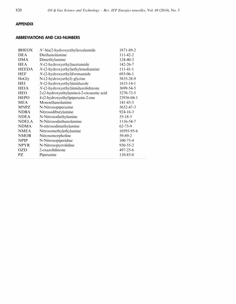
APPENDIX
ABBREVIATIONS AND CAS-NUMBERS
BHEOXDEADMAHEAHEEDAHEFHeGlyHEIHEIAHEOHEPOMEAMNPZNDBANDEANDELANDMANMEANMORNPIPNPYROZDPZ
N’-bis(2-hydroxyethyl)oxalamideDiethanolamineDimethylamineN-(2-hydroxyethyl)acetamideN-(2-hydroxyethyl)ethylenediamineN-(2-hydroxyethyl)formamideN-(2-hydroxyethyl) glycineN-(2-hydroxyethyl)imidazoleN-(2-hydroxyethyl)imidazolidinone2-(2-hydroxyethylamino)-2-oxoacetic acid4-(2-hydroxyethyl)piperazin-2-oneMonoethanolamineN-NitrosopiperazineNitrosodibutylamineN-NitrosodiethylamineN-NitrosodiethanolamineN-nitrosodimethylamineNitrosomethylethylamineNitrosomorpholineN-NitrosopiperidineN-Nitrosopyrrolidine2-oxazolidinonePiperazine
1871-89-2111-42-2124-40-3142-26-7111-41-1693-06-15835-28-91615-14-13699-54-55270-73-523936-04-1141-43-55632-47-3924-16-355-18-51116-54-762-75-910595-95-659-89-2100-75-4930-55-2497-25-6110-85-0
820 Oil & Gas Science and Technology – Rev. IFP Energies nouvelles, Vol. 69 (2014), No. 5


![Portfolio - GitHub Pages · 2019-07-03 · Portfolio Kim,Dongho [HEX1] Hexapedal (2018~2019) - 18~19 DOF - 큰 종횡비(긴 다리) - 높은 무게중심의 실험적인](https://img.pdfslide.net/doc/110x75/5edb276a7f762c49ee1347a7/portfolio-github-pages-2019-07-03-portfolio-kimdongho-hex1-hexapedal-20182019.jpg)