Embed Size (px)
Citation preview

Electrochemistry Communications 12 (2010) 86–89
Contents lists available at ScienceDirect
Electrochemistry Communications
journal homepage: www.elsevier .com/locate /e lecom
Formation of titanium oxide nanogrooves island arrays by anodization
Yue Chen a, Xiao-Ming Wang a, Shu-Shen Lu a,*, Xing Zhang b
a School of Chemistry and Chemical Engineering, Sun Yat-Sen University, Guangzhou 510275, Chinab School of Aerospace, Tsinghua University, Beijing 100084, China
a r t i c l e i n f o a b s t r a c t
Article history:Received 16 September 2009Received in revised form 13 October 2009Accepted 27 October 2009Available online 29 October 2009
Keywords:AnodizationTitanium oxideNanotube arraysNanogrooves island arrays
1388-2481/$ - see front matter � 2009 Elsevier B.V. Adoi:10.1016/j.elecom.2009.10.042
* Corresponding author. Fax: +86 20 84112150.E-mail address: [email protected] (S.-S. Lu)
In the present work, titanium oxide nanogrooves island arrays (NGIAs) surface is formed by anodizationof Ti foil in the high HF content electrolyte. The influences of anodization voltage and HF concentration ofelectrolyte on the formation of NGIAs are studied to control the depth and the distribution of nanogroo-ves. The formation mechanism of NGIAs is discussed. The strategy derived from the results is expected toapply to the NGIAs formation of other oxides which share the similar anodization behavior as titaniumoxide.
� 2009 Elsevier B.V. All rights reserved.
1. Introduction
TiO2 nanomaterials have attracted great attentions due to theirprospective applications in photocatalysis [1], solar cells [2], gassensors [3], electrochromic devices [4], wettability switchable sur-faces [5], self-cleaning surfaces [6] and nucleate boiling surfaces[7]. Ordered nanostructured surfaces, like grooves, holes, dots areof great interests for both fundamental research and technologicalapplications in many fields of modern science due to their uniquephysical and chemical properties [8]. In this paper, we present astrategy to fabricate various nanogrooves on the closed tips of ano-dic titanium oxide nanotube arrays (TNTAs), harvesting the nanog-rooves island arrays (NGIAs) surface.
Up to now, extensive efforts have been devoted to exploremethods for preparing nanostructured TiO2 [9], and anodizationis well known as a simple but efficient way for preparing largescale, vertically aligned TNTAs on the Ti substrate [10]. For the con-ventional TNTAs, each nanotube has a closed tip buried inside, andthe closed tip is semispherical and smooth. However, we discoverthat various nanotunnels can be formed at the interface betweenthe closed tip and the Ti substrate when anodization is carriedout in the high HF content electrolyte. The TNTAs layer can be suc-cessfully detached and transferred [11,12]. After detaching theTNTAs, plenty of nanogrooves exist on the nanotube tips at the bot-tom side of TNTAs, resulting in the NGIAs surface. Since the
ll rights reserved.
.
diameter of the tube cell can be tailored in a wide range [13] andthe geometry of the nanogrooves can be modified, the titaniumoxide NGIAs surfaces may potentially exhibit unique catalytical,optical and wetting characteristics, or may be used as stamps forsoft lithography. Moreover, the strategy introduced herein is ex-pected to form NGIAs of other oxides which have the similar anod-ization behavior as titanium oxide.
2. Experimental
Titanium foils with a thickness of 0.3 mm were mechanicallypolished with polishing-cloth, then ultrasonically cleaned in purewater, acetone and deionized water successively, dried in ambientair prior to the anodization. After the pretreatments, the sampleswith 4 cm2 exposed to the electrolytes were anodized at 40, 60,80 or 100 V (supplied by a DC power) for 2, 5, or 12 h, using atwo-electrode configuration with a piece of lead plate (9 cm2) asthe counter electrode. The distance between the anode and thecathode was maintained at 1 cm for all the experiments. Thehydrofluoric acids used in the experiments contain 40 wt.% HF.The electrochemical reactor was airproofed with polyethylenemembrane and kept in a 5 ± 0.5 �C bath in the anodization process.The anodization current was recorded by a multimeter which wasinterfaced with a computer. The surface morphology of the speci-mens was characterized by a scanning electron microscope (SEM,Quanta 400F, FEI/OXFORD/HKL) and an atomic force microscope(AFM, SPM-9500J3, SHIMADZU). The bottom view and side viewof TNTAs were obtained from the cracked films after bending thespecimens.
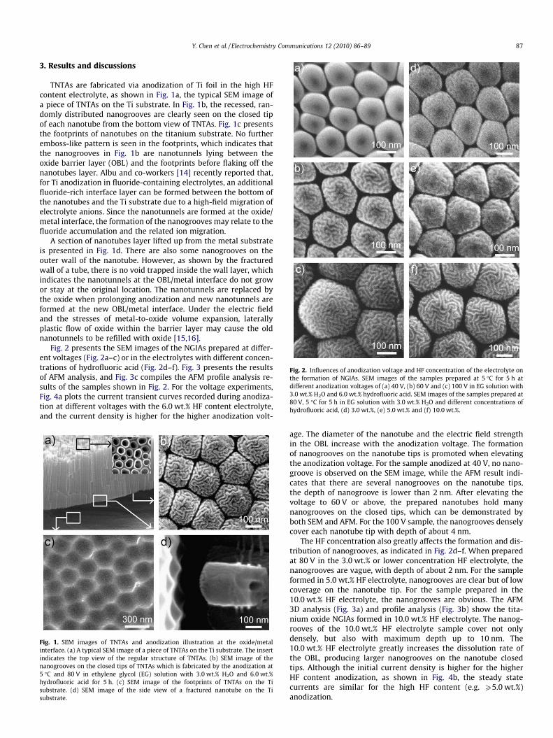
Fig. 2. Influences of anodization voltage and HF concentration of the electrolyte onthe formation of NGIAs. SEM images of the samples prepared at 5 �C for 5 h atdifferent anodization voltages of (a) 40 V, (b) 60 V and (c) 100 V in EG solution with3.0 wt.% H2O and 6.0 wt.% hydrofluoric acid. SEM images of the samples prepared at80 V, 5 �C for 5 h in EG solution with 3.0 wt.% H2O and different concentrations ofhydrofluoric acid, (d) 3.0 wt.%, (e) 5.0 wt.% and (f) 10.0 wt.%.
Y. Chen et al. / Electrochemistry Communications 12 (2010) 86–89 87
3. Results and discussions
TNTAs are fabricated via anodization of Ti foil in the high HFcontent electrolyte, as shown in Fig. 1a, the typical SEM image ofa piece of TNTAs on the Ti substrate. In Fig. 1b, the recessed, ran-domly distributed nanogrooves are clearly seen on the closed tipof each nanotube from the bottom view of TNTAs. Fig. 1c presentsthe footprints of nanotubes on the titanium substrate. No furtheremboss-like pattern is seen in the footprints, which indicates thatthe nanogrooves in Fig. 1b are nanotunnels lying between theoxide barrier layer (OBL) and the footprints before flaking off thenanotubes layer. Albu and co-workers [14] recently reported that,for Ti anodization in fluoride-containing electrolytes, an additionalfluoride-rich interface layer can be formed between the bottom ofthe nanotubes and the Ti substrate due to a high-field migration ofelectrolyte anions. Since the nanotunnels are formed at the oxide/metal interface, the formation of the nanogrooves may relate to thefluoride accumulation and the related ion migration.
A section of nanotubes layer lifted up from the metal substrateis presented in Fig. 1d. There are also some nanogrooves on theouter wall of the nanotube. However, as shown by the fracturedwall of a tube, there is no void trapped inside the wall layer, whichindicates the nanotunnels at the OBL/metal interface do not growor stay at the original location. The nanotunnels are replaced bythe oxide when prolonging anodization and new nanotunnels areformed at the new OBL/metal interface. Under the electric fieldand the stresses of metal-to-oxide volume expansion, laterallyplastic flow of oxide within the barrier layer may cause the oldnanotunnels to be refilled with oxide [15,16].
Fig. 2 presents the SEM images of the NGIAs prepared at differ-ent voltages (Fig. 2a–c) or in the electrolytes with different concen-trations of hydrofluoric acid (Fig. 2d–f). Fig. 3 presents the resultsof AFM analysis, and Fig. 3c compiles the AFM profile analysis re-sults of the samples shown in Fig. 2. For the voltage experiments,Fig. 4a plots the current transient curves recorded during anodiza-tion at different voltages with the 6.0 wt.% HF content electrolyte,and the current density is higher for the higher anodization volt-
Fig. 1. SEM images of TNTAs and anodization illustration at the oxide/metalinterface. (a) A typical SEM image of a piece of TNTAs on the Ti substrate. The insertindicates the top view of the regular structure of TNTAs. (b) SEM image of thenanogrooves on the closed tips of TNTAs which is fabricated by the anodization at5 �C and 80 V in ethylene glycol (EG) solution with 3.0 wt.% H2O and 6.0 wt.%hydrofluoric acid for 5 h. (c) SEM image of the footprints of TNTAs on the Tisubstrate. (d) SEM image of the side view of a fractured nanotube on the Tisubstrate.
age. The diameter of the nanotube and the electric field strengthin the OBL increase with the anodization voltage. The formationof nanogrooves on the nanotube tips is promoted when elevatingthe anodization voltage. For the sample anodized at 40 V, no nano-groove is observed on the SEM image, while the AFM result indi-cates that there are several nanogrooves on the nanotube tips,the depth of nanogroove is lower than 2 nm. After elevating thevoltage to 60 V or above, the prepared nanotubes hold manynanogrooves on the closed tips, which can be demonstrated byboth SEM and AFM. For the 100 V sample, the nanogrooves denselycover each nanotube tip with depth of about 4 nm.
The HF concentration also greatly affects the formation and dis-tribution of nanogrooves, as indicated in Fig. 2d–f. When preparedat 80 V in the 3.0 wt.% or lower concentration HF electrolyte, thenanogrooves are vague, with depth of about 2 nm. For the sampleformed in 5.0 wt.% HF electrolyte, nanogrooves are clear but of lowcoverage on the nanotube tip. For the sample prepared in the10.0 wt.% HF electrolyte, the nanogrooves are obvious. The AFM3D analysis (Fig. 3a) and profile analysis (Fig. 3b) show the tita-nium oxide NGIAs formed in 10.0 wt.% HF electrolyte. The nanog-rooves of the 10.0 wt.% HF electrolyte sample cover not onlydensely, but also with maximum depth up to 10 nm. The10.0 wt.% HF electrolyte greatly increases the dissolution rate ofthe OBL, producing larger nanogrooves on the nanotube closedtips. Although the initial current density is higher for the higherHF content anodization, as shown in Fig. 4b, the steady statecurrents are similar for the high HF content (e.g. P5.0 wt.%)anodization.

Fig. 3. AFM 3D image (a) and AFM profile analysis (b) of the NGIAs formed by theanodization at 5 �C and 80 V in EG solution with 3.0 wt.% H2O and 10.0 wt.%hydrofluoric acid for 5 h. (c) Statistical graph of the AFM profile analysis of thesamples shown in Fig. 2: maximum depth of the nanogroove versus the anodizationvoltage and HF concentration.
Fig. 4. Current transient profiles recorded during the anodization. (a) At differentvoltages in the electrolyte with 3.0 wt.% H2O and 6.0 wt.% hydrofluoric acid. (b) At80 V in the electrolytes with 3.0 wt.% H2O and different concentration of HF. Theinsets detail the current behaviors at the initial state of the anodization.
88 Y. Chen et al. / Electrochemistry Communications 12 (2010) 86–89
4. Conclusions
In summary, this communication firstly reports the formationof titanium oxide NGIAs surface by anodization. The geometry ofthe nanogrooves is greatly affected by the HF content in the elec-trolyte and the anodization voltage. High HF concentration (e.g.P5.0 wt.% at 80 V) is the key factor for the formation of nanogroo-ves. Elevating the anodization voltage can promote the nanogroo-ves formation. The results may be helpful for directly illustratingthe dynamic physico-chemical process at the oxide/metal interfaceduring the anodization.
Acknowledgments
This work was supported by the National Natural Science Foun-dation of China (Grant Nos. 50976126 and 50730006).
References
[1] M.R. Hoffmann, S.T. Martin, W. Choi, D.W. Bahnemann, Chem. Rev. 95 (1995)69–96.
[2] M. Grätzel, Nature 414 (2001) 338–344.[3] O.K. Varghese, D. Gong, M. Paulose, K.G. Ong, E.C. Dickey, C.A. Grimes, Adv.
Mater. 15 (2003) 624–627.[4] Y.-C. Nah, A. Ghicov, D. Kim, S. Berger, P. Schmuki, J. Am. Chem. Soc. 130 (2008)
16154–16155.[5] E. Balaur, J.M. Macak, L. Taveira, P. Schmuki, Electrochem. Commun. 7 (2005)
1066–1070.

Y. Chen et al. / Electrochemistry Communications 12 (2010) 86–89 89
[6] I.P. Parkin, R.G. Palgrave, J. Mater. Chem. 15 (2005) 1689–1695.[7] Y. Chen, D.C. Mo, H.B. Zhao, N. Ding, S.S. Lu, Sci. China Ser. E 52 (2009) 1596–
1600.[8] M. Geissler, Y. Xia, Adv. Mater. 16 (2004) 1249–1269.[9] X. Chen, S.S. Mao, Chem. Rev. 107 (2007) 2891–2959.
[10] J.M. Macak, H. Tsuchiya, A. Ghicov, K. Yasuda, R. Hahn, S. Bauer, P. Schmuki,Curr. Opin. Solid State Mater. Sci. 11 (2007) 3–18.
[11] S.P. Albu, A. Ghicov, J.M. Macak, R. Hahn, P. Schmuki, Nano Lett. 7 (2007) 1286–1289.
[12] J.H. Park, T.-W. Lee, M.G. Kang, Chem. Commun. (2008) 2867–2869.[13] S. Bauer, S. Kleber, P. Schmuki, Electrochem. Commun. 8 (2006) 1321–
1325.[14] S.P. Albu, A. Ghicov, S. Aldabergenova, P. Drechsel, D. LeClere, G.E. Thompson,
J.M. Macak, P. Schmuki, Adv. Mater. 20 (2008) 4135–4139.[15] D.J. LeClere, A. Velota, P. Skeldon, G.E. Thompson, S. Berger, J. Kunze, P.
Schmuki, H. Habazaki, S. Nagata, J. Electrochem. Soc. 155 (2008) C487–C494.[16] J.E. Houser, K.R. Hebert, Nat. Mater. 8 (2009) 415–420.


![Nanoporous TiO2 and WO 3 Films by Anodization of ...1].pdfNanoporous TiO2 and WO 3 Films by Anodization of Titanium and Tungsten Substrates: Influence of Process Variables on Morphology](https://img.pdfslide.net/doc/110x75/60c30184963cb974b75d82dd/nanoporous-tio2-and-wo-3-films-by-anodization-of-1pdf-nanoporous-tio2-and.jpg)