Embed Size (px)
Citation preview

© ISO 2002 – All rights reserved
C:\Dati_Guglielmo_020305\ISO_largeyachts_08.doc Basic template BASICEN3 2002-06-01
Reference number of working document: ISO/TC 8/SC 12 N 003 Date: 2007-03-15
Formerly ISO/TC 8/SC 1 doc. N 203
Committee identification: ISO/TC 8/SC 12
Secretariat: UNI
Large Yachts — Windows, portlights — Strength and watertightness requirements [WI 12.01]
Warning
This document is not an ISO International Standard. It is distributed for review and comment. It is subject to change without notice and may not be referred to as an International Standard.
Recipients of this draft are invited to submit, with their comments, notification of any relevant patent rights of which they are aware and to provide supporting documentation.
Document type: International standard Document subtype: if applicable Document stage: (20) Preparation Document language: E

WORKING DRAFT ISO/WD nnn-n
© ISO 2002 – All rights reserved 1
Copyright notice
This ISO document is a working draft or committee draft and is copyright-protected by ISO. While the reproduction of working drafts or committee drafts in any form for use by participants in the ISO standards development process is permitted without prior permission from ISO, neither this document nor any extract from it may be reproduced, stored or transmitted in any form for any other purpose without prior written permission from ISO.
Requests for permission to reproduce this document for the purpose of selling it should be addressed as shown below or to ISO’s member body in the country of the requester:
[Indicate : the full address telephone number fax number telex number and electronic mail address
as appropriate, of the Copyright Manager of the ISO member body responsible for the secretariat of the TC or SC within the framework of which the draft has been prepared]
Reproduction for sales purposes may be subject to royalty payments or a licensing agreement.
Violators may be prosecuted.

2 © ISO 2002 – All rights reserved
Contents Page
1 Scope ......................................................................................................................................................4 2 Normative references ............................................................................................................................4 3 Terms and definitions ...........................................................................................................................5 4 Symbols (and abbreviated terms) ........................................................................................................8 5 General Requirements ..........................................................................................................................9 5.1 General....................................................................................................................................................9 5.2 Strength ..................................................................................................................................................9 5.3 Watertightness .......................................................................................................................................9 6 Plate materials......................................................................................................................................10 7 Specific requirements .........................................................................................................................11
8 Scantling determination of plate ………………………………………………………………………… 13
9 Appendix A (normative) Test Procedure for Hydrostatic Structural Testing of Marine Windows . 15
10 Appendix B (normative) Gluing Tests …………………………………………………………………..18
The table of contents is an optional preliminary element, but is necessary if it makes the document easier to consult. The table of contents shall be entitled “Contents” and shall list clauses and, if appropriate, subclauses with titles, annexes together with their status in parentheses, the bibliography, indexes, figures and tables. The order shall be as follows: clauses and subclauses with titles; annexes (including clauses and subclauses with titles if appropriate); the bibliography; indexes; figures; tables. All the elements listed shall be cited with their full titles. Terms in the “Terms and definitions” clause shall not be listed in the table of contents.

© ISO 2002 – All rights reserved 3
Foreword
ISO (the International Organization for Standardization) is a worldwide federation of national standards bodies (ISO member bodies). The work of preparing International Standards is normally carried out through ISO technical committees. Each member body interested in a subject for which a technical committee has been established has the right to be represented on that committee. International organizations, governmental and non-governmental, in liaison with ISO, also take part in the work. ISO collaborates closely with the International Electrotechnical Commission (IEC) on all matters of electrotechnical standardization.
International Standards are drafted in accordance with the rules given in the ISO/IEC Directives, Part 2.
The main task of technical committees is to prepare International Standards. Draft International Standards adopted by the technical committees are circulated to the member bodies for voting. Publication as an International Standard requires approval by at least 75 % of the member bodies casting a vote.
Attention is drawn to the possibility that some of the elements of this document may be the subject of patent rights. ISO shall not be held responsible for identifying any or all such patent rights.
ISO nnn-n was prepared by Technical Committee ISO/TC 000, TC title, Subcommittee SC 0, SC title.
This second/third/... edition cancels and replaces the first/second/... edition (ISO nnn-n:19xx), [clause(s) / subclause(s) / table(s) / figure(s) / annex(es)] of which [has / have] been technically revised.
ISO nnn consists of the following parts, under the general title Introductory element — Main element:
Part n: Part title
Part [n+1]: Part title
Part [n+2]: Part title
The foreword shall appear in each document. It shall not contain requirements, recommendations, figures or tables.
It consists of a general part and a specific part. The general part (supplied by the Central Secretariat of ISO) gives information relating to the organization responsible and to International Standards in general, i.e.
a) the designation and name of the committee that prepared the document,
b) information regarding the approval of the document, and
c) information regarding the drafting conventions used, comprising a reference to the ISO/IEC Directives, Part 2.
The specific part (supplied by the committee secretariat) shall give a statement of significant technical changes from any previous edition of the document and as many of the following as are appropriate:
d) an indication of any other international organization that has contributed to the preparation of the document;
e) a statement that the document cancels and replaces other documents in whole or in part;
f) the relationship of the document to other documents.

4 © ISO 2002 – All rights reserved
Large Yachts — Windows, portlights — Strength and watertightness requirements.
1 Scope
This International Standard specifies technical requirements for windows and portlights on Large Yachts, taking into account its design category (short range or unrestricted), and the location of the appliance.
Large Yachts are intended as ships of LOA (Length Over All) over 24 m, in commercial use for sport or pleasure and which carries no cargo and no more than 12 passengers and, in any case, of no more than 3000GT.
This International Standard is intended to be used for Large Pleasure Yachts and for Large Yachts engaged in commercial services (pleasure vessels “engaged in trade” for the purpose of Article 5- Exceptions of ICLL).
The appliances considered in this International Standard are only those that are critical for the ship watertightness, i.e. those that could lead to flooding in case of rupture of the plate.
2 Normative references
The following referenced documents are indispensable for the application of this document. For dated references, only the edition cited applies. For undated references, the latest edition of the referenced document (including any amendments) applies.
ISO 6345:1990, Shipbuilding and marine structures – Windows and side scuttles – Vocabulary
ISO 5779:1987, Shipbuilding – Positioning
ISO 3903:1993, Shipbuilding and marine structures – Ships’ ordinary rectangular windows
ISO 1751:1993, Shipbuilding and marine structures – Ships’ side scuttles
ISO 21005:2004, Shipbuilding and marine technology – Thermally toughened safety-glass panes for windows and side scuttles
ISO 614:1989, Shipbuilding and marine structures – Toughened safety glass panes for rectangular windows and side scuttles – Punch method of non-destructive strength testing
ISO 5797:2004, Ships and Marine Technology –Windows and side scuttles for fire-resistant constructions
EN 1288-3:2000, Determination of the bending strength of glass (four points bending test)
EN 12150-1:2000 Thermally Toughened soda lime silicate safety glass – Part 1: Definition and description
ISO 17025:2000, General Requirements for the competence of testing and calibration laboratories

© ISO 2002 – All rights reserved 5
3 Terms and definitions
For the purposes of this document, the terms and definitions given in ISO 6345:1990 and the following apply.
3.1 Appliance Device made of a plate and possibly a framing system, used to cover an opening in the hull or superstructure of a ship.
3.2 Plate Sheet of material, which may be transparent, that is fixed on the ship structure either directly or via framing system.
3.2.1 Glazing Transparent or translucent plate.
3.2.2 Unsupported dimensions of a plate Clear dimensions between the supports bearing the plate.
3.3 Window / Portlight Glazed appliances, the term portlight is used for small windows.
3.4 Deadlight / Storm Shutter Secondary watertight closure fitted to a window and which can be fitted inside or outside the plate.
3.5 Flag Administration The Government of the State whose flag the ship is entitled to fly. 3.6 Design Category Description of the navigation limitations for which ship is assessed to be suitable. 3.6.1 Design Category: Unrestricted Ship without GT limitations or operating restrictions.
3.6.2 Design Category: Short Range Ship under 300 GT restricted to operating in forecast or actual wind of a maximum Beaufort Force 4 and within 90 nautical miles of a safehaven.
3.7 Sail Ship Ship for which the primary means of propulsion is by wind power.
3.8 Motor Ship Ship for which the primary means of propulsion is engine power.
3.9 Waterline Side projection of the floatation plan, when the boat is upright and in fully loaded ready-to-use conditions.
3.10 Length Overall – LOA length overall - LOA means the distance between the foreside of the foremost fixed permanent structure and the afterside of the aftermost fixed permanent structure; and "fixed permanent structure" includes any portion of the hull which is capable of being detached, but which must be fixed in place during the normal operation of the vessel. It does

6 © ISO 2002 – All rights reserved
not include functional arrangements such as safety rails, bowsprits, pulpits, stemhead fittings, rudders, steering gear, outdrives, outboard motors, propulsion machinery, diving platforms, boarding platforms, rubbing strips and fenders.
3.11 Length - LWL Length LWL means 96% of the total length on a waterline of a ship at 85% of the least moulded depth measured from the top of the keel, or the length from the fore-side of the stem to the axis of the rudder stock on that waterline, if that be greater. In ships designed with a rake of keel the waterline on which this s measured shall be parallel to the designed waterline.
3.12 Beam - B Maximum width of the boat at any location along its length.
3.11 Freeboard Deck Has the meaning given in annex I of ICLL. The freeboard deck is the uppermost complete deck exposed to weather and sea which has permanent means of closing all openings in the weather part thereof, and below which all openings in the side of the ship are fitted with permanent means of watertight closing.
3.11.1 Weather Deck The uppermost complete weathertight deck fitted as an integral part of the vessel’s structure and which is exposed to the sea and weather. 3.11.2 Weathertightness Weathertight has the meaning given in annex I of ICLL , it means that in any sea conditions water will not penetrate into the ship. 3.12 Watertightness. Capacity of an appliance to prevent penetration of water into the ship in any direction.
3.13 Strength Capacity of an appliance to maintain full structural integrity under the action of loads. 3.14 Basic Design Loads External hydrostatic loads according to which appliance strength and watertightness has to be demonstrated. 3.15 Hull Part of the ship situated below freeboard deck. 3.16 Superstructure Superstructure has the meaning given in annex I of ICLL and is normally intended as part of the ship situated above freeboard deck or the weather deck.
3.16.1 Superstructure Order Superstructure decks are identified by their position starting from the Freeboard deck which is the first superstructure order (1st tier)
3.16.2 Wheelhouse Control position occupied by the officer of the watch who is responsible for the safe navigation of the vessel.

© ISO 2002 – All rights reserved 7
3.17 Appliance position Appliance position is defined first by its location above or below freeboard deck, if located below freeboard deck its position is hull position. If appliance is located above the freeboard deck its location is Superstructure – tier order. Finally appliance position will be defined as: Front, Side, Aft / other.
3.18 Plate end connection 3.18.1 Semi-fixed - SF plate Plate fixed in a way to restrict deflection and prevent lateral movements at its boundaries. Example: Framed or unframed plate if bolted and/or glued. 3.18.2 Simply Supported – SS plate Plate that can deflect at his boundaries and/or perform lateral movements Example: Unframed plate hinged or sliding. 3.19 Glass material 3.19.1 Thermally toughened glass Glass where strength increase is obtained by the introduction of permanent compression stress, generated by a thermal treatment, on the external side portions of its cross section.
3.19.2 Chemically toughened glass Glass where strength increase is obtained by the introduction of permanent compression stress, generated by chemical treatment, on the external side portions of its cross section.
3.19.3 Toughened glass with no residual permanent stress Glass where strength increase is obtained without the introduction of permanent compression stress in any portion of its cross section. 3.19.4 Monolithic glass Glazing consisting of one ply of glass
3.19.5 Laminated glass Multi-layer pane made of glass plies, plastic plies or other glazing materials. The plies are kept together by suitable plastic adhesive inter-layers.
3.19.6 Insulating Glazing Units (IGU) Glazing made of multiples panes either monolithic or laminated separated by sealed gaps filled with gas (air, argon etc.) 3.19.7 Fire resistant Glazing Glazing made of special material that result in a specific fire resistance. Windows and portlights for fire resistant constructions shall meet the requirements of the FTP code according to SOLAS 74, Chapter ii-2, Regulation 3. The general requirements of such windows are defined in ISO 5797:2004. 3.19.8 Case depth - CD When a glass ply is toughened by the introduction of permanent compression stress on the external side portions of its cross section (balanced by tensile stress in a inner cross section portion), case depth - CD is the depth of the compression stress measured from the external surface to the inner cross section point where compression stress is null.

8 © ISO 2002 – All rights reserved
3.19.9 Surface Compression - SC When a glass ply is toughened by the introduction of permanent compression stress on the external side portions of its cross section (balanced by tensile stress in a inner cross section portion), surface compression - SC is the value of compression stress taken at the external surface. 3.19.10 Modulus of Rupture - M.O.R Ultimate flexural strength at rupture of a glass sample measured in a flexural test arrangement.
4 Symbols (and abbreviated terms)
A paragraph.
The Symbols (and abbreviated terms) clause is an optional element giving a list of the symbols and abbreviated terms necessary for the understanding of the document.
Unless there is a need to list symbols in a specific order to reflect technical criteria, all symbols should be listed in alphabetical order in the following sequence:
upper case Latin letter followed by lower case Latin letter (A, a, B, b, etc.);
letters without indices preceding letters with indices, and with letter indices preceding numerical ones (B, b, C, Cm, C2, c, d, dext, dint, d1, etc.);
Greek letters following Latin letters (Z, z, Α, α, Β, β, …, Λ, λ, etc.);
any other special symbols.
For convenience, this element may be combined with the Terms and definitions clause in order to bring together terms and their definitions, symbols, abbreviated terms and perhaps units under an appropriate composite title, for example “Terms, definitions, symbols, units and abbreviated terms”.

© ISO 2002 – All rights reserved 9
5 General Requirements
5.1 General
Other International standards, e.g. dealing with stability and buoyancy, may have restrictions on the position of appliances which are outside the scope of this international Standard and which are therefore not treated here. It is however necessary for the builder or user to ensure that the appliances comply with other relevant International Standards.
5.2 Strength
The strength of windows and portholes shall meet the requirement of this International Standard and of the relevant International Standard cited in the normative references clause when their type is covered. For the scope of this standard strength is considered only with reference to external hydrostatic loads coming from weather and sea conditions. Strength requirement is fulfilled according to the following criteria:
- In case the window type is covered by an existing ISO standard (See 2. Normative References)
- According to the calculation method outlined in clause 8
- According the hydrostatic test procedure outlined in Annex A
External hydrostatic loads (Basic Design Loads) will be the only loads considered for strength requirement fulfilment.
5.3 Watertightness
To avoid flooding, all appliances shall be designed and fixed to prevent substantial ingress of water in the ship. The watertightness requirement is fulfilled according to the following criteria:
- In case the window type is covered by an existing ISO standard (See 2. Normative References)
- According to the clause 7.2 (Fastening requirements)
- According the hydrostatic test procedure outlined in Annex A
10 © ISO 2002 – All rights reserved
6 Plate materials
6.1 General
Appliances plates shall be made of:
- transparent glazing materials, such as toughened glass (Thermally-TT or Chemically CT), polycarbonate (PC) or poly(metyl)metacrilate (PMMA).
- any other material of strength and stiffness equivalent to those cited above.
6.2 Glass
6.2.1 Restrictions of usage
Only toughened glass is allowed as plate material or as plies material for laminated constructions. In wheelhouse glazing, for both front and sides positions, in case of glazing breakage, the pane shall remain in its position and watertightness and residual vision are to be maintained. In wheelhouse glazing, for both front and side positions, IGU glazing are not allowed because of possible optical distorsion. For monolithic construction only toughened glass meeting the requirements of the fragmentation test outlined in EN 12150:2000 Clause 8 shall be used.
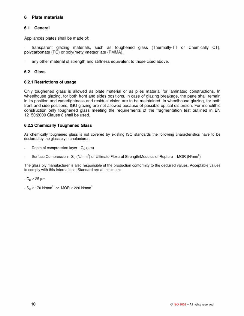
6.2.2 Chemically Toughened Glass
As chemically toughened glass is not covered by existing ISO standards the following characteristics have to be declared by the glass ply manufacturer:
- Depth of compression layer - CD (µm)
- Surface Compression - SC (N/mm2) or Ultimate Flexural Strength/Modulus of Rupture – MOR (N/mm2)
The glass ply manufacturer is also responsible of the production conformity to the declared values. Acceptable values to comply with this International Standard are at minimum:
- CD ≥ 25 µm
- SC ≥ 170 N/mm2 or MOR ≥ 220 N/mm2

© ISO 2002 – All rights reserved 11
7 Specific requirements
7.1 End connection and location of appliance
7.1.1 Simply supported connected plates
Simply supported plates shall not be used in Hull or Superstructure positions where they may come in contact with hydrostatic loads. On other positions simply supported plates may be used providing that the following condition is met:
- The fixing device of the plate (hinge bolts, fixing knob, etc) are not spaced more than 250 mm
7.1.2 Glass Plates
Direct metal to glass contact shall always to be avoided.
7.2 Fastening Requirements 7.2.1 Fastening of plates and frames Plates and frames can be fastened by mechanical means, glue or elastomeric joints. All types of fastening shall ensure watertightness of the plate to the frame and resistance to loads due to normal operating pressure.
Every part of the mechanical elements connecting appliances to the rest of the ship shall be capable of withstanding , without breakages, twice the force F (kN) induced by the pressure loads defined in clause 8.
DPbaF ⋅⋅⋅= 2
where a and b are the unsupported dimensions of the appliance (or its equivalents as defined in Annex C) expressed in meters, and PD (kPa) is the basic design load defined in clause 8. This analysis can be performed by calculation or by test and has to be extended to all the mechanical elements including hinges, locks, supporting frames and gluing joints.
7.2.2 Fastening of glued plates
Glued joints shall be resistant to (or protected against) sunlight (UV-Ultraviolet radiation, heat) and all the environmental effects or cleaning chemicals encountered in the manufacturing and use of the ship. The manufacturer’s gluing procedure and conditions must always be declared and followed and the bond strength checked by calculation to meet pressure loads as defined in clause 8. The gluing operators shall be qualified and authorized by the glue manufacturer. Glued joints shall fulfil the requirements of one of the following items:
a) The inside pressure test b) The separation test
The above requirements shall be verified after any change in material or gluing procedure. Plates, with or without framing are considered glued if they are fastened with mechanical devices, such as bolts, rivets or screws, spaced more than 20 times the nominal plate thickness defined in clause 8.
7.3 Special Requirements
7.3.1 Appliances fitted in hull
7.3.1.1 Height above waterline
The lower edge of any opening appliance shall be placed at least 500 mm above the waterline or 2,5 % of maximum beam – B whichever is greater, the ship being in the fully loaded ready-for-use condition and upright. Limitations in maximum area of appliances are left to flag administration requirements.
7.3.1.2 Opening side
Any opening appliance shall open inwards.

12 © ISO 2002 – All rights reserved
7.3.1.3 Protection
No part of the plate or its framing shall extend outside the local vertical tangent to the hull, deck, rubbing strake, fixed tender, or of a built in fairing which is an integral part of the hull. Figure 1 explains this requirement.
Figure 1 – Sketch explaining clause 7.3.1.2
7.3.1 Deadlights and Stormshutters
7.3.2.1 Appliances located below the freeboard deck or weather deck
Deadlights are requested for any appliance located in the Hull below the freeboard deck.
7.3.2.2 Appliances located above the freeboard deck or weather deck
Stormshutters are normally requested for Unrestricted design category appliances located in front and side positions on 1st Superstructure tier and in front position on 2nd Superstructure tier. Stormshutters are not requested on Superstructure for Short range design category. Stormshutters may be avoided on 1st and 2nd Superstructure tier for Unrestricted design category if one of the following conditions applies: - The plate is of laminated construction and its equivalent plate thickness is 1.3 times higher than the one calculated in clause 8. In that case only a blanking plate is requested. - The plate is of laminated construction and in the plate construction there is an additional 3 mm ply of polycarbonate extended to the support of the plate - The hydrostatic load test is passed at 4 times the relevant design load without breakages and the broken window (at least one ply broken) withstand the design load pressure maintaining full watertightness.

© ISO 2002 – All rights reserved 13
8. Scantling determination of plates
8.1 Basic plate thickness determination
The formula given in 8.1.1 is valid for rectangular plates. For circular plates, replace b by d, which is the unsupported diameter.
For plates having unsupported shapes different from a rectangle or a circle, the approximations of annex C shall be used to determine the “equivalent” unsupported dimensions.
8.1.1 Basic thickness -tO
A
DO
Pbt
σβ ⋅
⋅=
where:
tO (mm) – is the basic plate thickness
b (mm) – is the unsupported short side of a rectangular plate or “equivalent short side” of a plate
β - is the plate-aspect ratio coefficient (see 8.3)
PD (Pa) – is the basic design pressure
σA (Pa) – is the allowable flexural stress of the material
8.2 Plate aspect ratio coefficient - ββββ
The plate aspect ratio coefficient, β shall be taken from Figure 2 (taken from ISO 21005:2004) for rectangular plates and from table 1 for circular plates. The β coefficient is a function of the aspect ratio AR= a/b which is the ratio of the unsupported dimensions where a and b are respectively the long and short unsupported dimensions (or their equivalent dimensions determined according to annex C) of a rectangular plate expressed in millimetres.

14 © ISO 2002 – All rights reserved
Figure 2 – Plate aspect ratio coefficient - ββββ (X=AR)
Table 1 - Value of ββββ for Circular plates
Values of β for Circular plates 0,25
8.3 Basic design pressure
The basic design pressure for calculation of the plate thickness shall be selected from Table 2 Table 2- Basic Design Pressure - PD (kPa)
Service Type Navigation restrictions
HULL SUPERSTRUCTURE
1st tier Front 2nd tier Front Fronts above 2nd tier and all Sides
and Aft
Short Range 120 35 15 10 Commercial Service
Unrestricted 120 45+LWL/10 35 15
Pleasure 70 15 10 10
8.4 Ultimate Flexural Strength - MOR
The values of ultimate flexural strength of the plate material are the manufacturer’s stated values. Values should be given for glass when tested according to EN 1288-3:2000. Means values are acceptable if test has been performed at least on 30 samples, if test has been performed on less than 30 samples the accepted value is the one corresponding to the lower confidence interval value evaluated by the T-student distribution at 95% probability.In the absence of such data the typical values given in table 3 may be used.
8.5 Design factor, allowable flexural strength and minimum plate thickness
The allowable flexural stress of the material σA is determined from:
γσσ UFS
A =
where γ is the design factor given in table 4.
Table 3 - Mechanical properties of materials
Material Acronym MOR - σσσσUFS (MPa) Design Factor -γγγγ Allowable Strength σσσσA (MPa)
Poly(methyl)methacrilate PMMA 110 3,5 31,4
Policarbonate PC 90 3,5 25,7
Thermally toughened Glass
TT 160 4,0 40,0
Chemically toughened Glass
CT 220 4,0 55,0

© ISO 2002 – All rights reserved 15
8.6 Selection of monolithic plate thickness
The value of the actual plate thickness ta, expressed in millimetres, to be used in case of monolithic construction, shall be the greatest of the following:
- the basic plate thickness, tO calculated in 8.1.1
- the minimum plate thickness, tm according to the relevant ISO Standard ( ISO 3903:1993 , ISO 21005:2004) when applicable, in any case should be always tm≥ 8 mm.
With commercially available plates, the nominal commercial thickness will be selected as the first upper integer above the calculated basic thickness.
8.7 Laminated glass thickness
In order to calculate the thickness of a laminated glass construction made of n plies of thicknesses: t1,t2,...,tn, the equivalent thickness of laminated construction is calculated and compared with the basic thickness calculated according to clause 8.1.1 as :
a) if the difference in thickness between any of two glass plies is less than or equal to 2 mm when plies are up to 12 mm and less or equal to 4 mm when glass plies are up to 19 mm and the thickness of the plastic interlayer is less than or equal to 2 mm, than:
)....( 222
21 neq tttt +++=
and
teq ≥ tO
b) If the conditions of a) above are not met, each ply shall be considered as stressed according to its section modulus and shall be analyzed according to clause 8.
c) Polycarbonate, Poly(metyl)metacrilate plies or any plastic foil or ply in construction with glass plies are not considered providing that their thickness is less or equal to 3 mm and the correspondent interlayer is less or equal to 2 mm. If their thickness exceed 3mm they are considered to decouple the laminates construction and the two parts of the construction have to considered as independent.
Note: If the PC, PMMA and plastic foil or ply is the outer ply of a construction, its influence is negligeable regardless of their thickness.
8.8 IGU panes thickness determination The outer pane of the IGU is to be calculated according to 8.6 if monolithic or 8.7 if laminated using the relevant design pressure loads from table 3. The inner pane will be calculated again a according to 8.6 if monolithic or 8.7 if laminated using the relevant design pressure loads from table 3 reduced by a load sharing coefficient that will be at minimum 0.3. 8.9 Fire resistant Glazing The strength requirement for fire resistant glazing will be fulfilled if the construction will be evaluated according to ISO 5797:2004

16 © ISO 2002 – All rights reserved
Annex A (Normative)
Test Procedure for Hydrostatic Structural Testing of Marine Windows
A1. Scope
This procedure has the purpose to establish an experimental method for proof testing of marine windows to asses their strength and watertightness characteristics. The test has to be understood as a test on the complete window assembly including the fixing system. The window will be identified in two main components:
- Glazing - Edge fixing system (jamming, framing, gluing or any mechanical/chemical method to join the glazing to the ship structures). Glazing can be identified according to the following criteria:
- Monolithic glass pane - Laminated glass pane with adhesive interlayers - Composite laminated with glass plies, plastic plies (Polycarbonate, Acrylic or others plastic materials) and suitable adhesive interlayers Each glass pane can be described in terms of the toughening process:
- Thermally Toughened - Chemically Toughened A2. Motivations
In some situations the calculated thickness or equivalent thickness may be too conservative. In this case or when innovative materials are used the strength and watertightness characteristics of the windows cannot be predicted according to the international standards above reported or to clause 8 calculations. For this reason a suitable test can be introduced to evaluate both strength and watertightness requirements.
A3. Apparatus
A3.1 Testing assembly
The test shall be carried out using a testing chamber with a opening and a corresponding fixing system of the window to be tested, to the chamber edges. The window to be tested (sample) has to be constructed using the same materials and according to the cross-sections designed in the installation on the ship. The sample has to be fixed to the testing assembly in such a way to guaranty water tightness and not alter the real assembly condition.
The filling water line and the chamber pressure measuring line should be separated, that is the chamber pressure reading instrument should be connected to a line different from the water loading line.
The chamber is to be filled with water, during filling care is to be taken to eliminate or at least minimise air trapping inside the chamber.
Test apparatus like testing chamber and the hydraulic circuits to pressurize the test chamber have to be designed and constructed in a consistent way, it is a technical responsibility of test operators to run tests on tests apparatus meeting safety criteria, this test may result in potentially dangerous operations and situations.
A3.2 Measuring Instruments
The following measuring instruments are required :
Mandatory measuring instruments:
- A calibrate laboratory manometer to measure the water pressure in the test chamber

© ISO 2002 – All rights reserved 17
Optional measuring instruments:
- 0.1 mm precision dial gauges to measure the glazing central deflection - A remote pressure transducer able to read the internal pressure of the chamber and to record the values on a suitable support - a suitable strain gauge system to measure the external glazing stress it is a technical responsibility of test operators to run tests with measuring instruments meeting metrological criteria in terms of reference to international measuring unit system, accuracy and repeatability.
A4. Sample
Sample dimensions will be according to the required dimensions and the cross section will be according to the original design. A complete engineering documentation (drawings and descriptions) has to be provided indicating :
Glazing:
Geometric Cross section with full indication of thickness of the glass or plastic plies and of the laminating adhesive interlayers. Glass plies will be identified in terms of toughening process treatment (Thermal or Chemical Strengthening) and relevant indications of toughening levels in terms of surface compression or ultimate tensile strength and compression layer depth for the chemically strengthened glass panes. Plastic plies will be identified in terms of their chemical type (example: Polycarbonate or Acrylics). Interlayers will be also identified in terms of their chemical type (example: Polyvinylbutyrrale or Polyurethane).
Fixing System:
Geometric Cross section with full indication of thickness and materials identification of all the components of the fixing system.
The engineering documentation of the window sample has to be considered as part of the test report and has to be fully included in the test report.
When the test has the purpose to be a part of a type approval procedure also relevant production documents of the sample components (route cards, intermediate quality control reports and other relevant documents) have to be provided and considered as a part of the test report.
A5. Test Procedure
The tests has to be carried out by laboratories or institutions meeting, in general, the requirements of ISO 17025: and, specifically by qualified test operators. A qualified test operator is a technician or scientist with an engineering or technical or scientific background with an extended experience (at least 5 years) in laboratory physical/mechanical tests.
The test will be carried out as follows :
Before the installation of the window sample in the testing chamber, overall dimensions of the window components should be taken and recorded.
After the complete installation of the window sample in the testing chamber the unsupported glazing dimensions will be taken and recorded.
Test chamber will be water filled taking all the necessary precautions to evacuate trapped residual air.
Preliminary gauges calibrations and preparation will be performed by test operators.
A design test pressure (design load pressure - PD) will be previously established according to table 3.
Chamber pressure will be raised up to PD and there maintained for at least 300 seconds (five minutes).
After this step the pressure in the test chamber will be raised up to 4 times the design load pressure – 4 PD.
When possible central deflection and chamber pressure will be measured and recorded continuously during the test .
18 © ISO 2002 – All rights reserved
Any event like loss of water tightness (from the glazing or from the fixing system) or glass plies breakage will be recorded by the test operators with the relevant test chamber pressure.
Eventually, and if possible, the sample will be taken to final collapse. For stormshutters exemption, if the sample does not break, it will be intentionally broken by a mechanical mean (sharp hammer) and it will be tested in this condition at the PD .
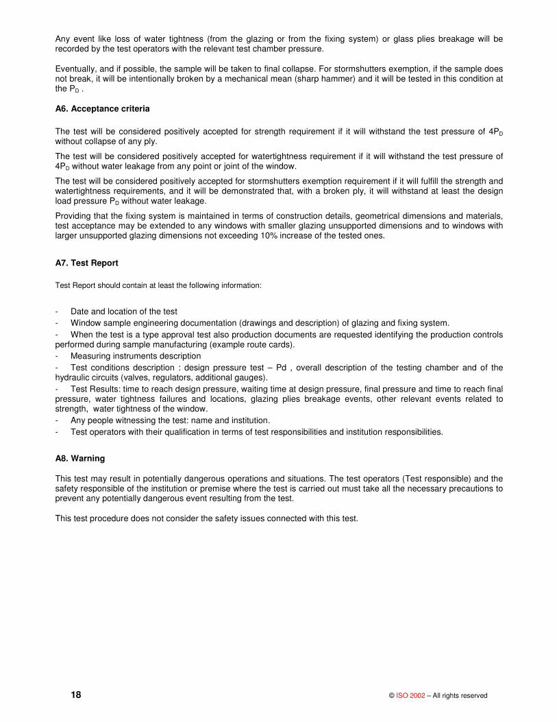
A6. Acceptance criteria
The test will be considered positively accepted for strength requirement if it will withstand the test pressure of 4PD without collapse of any ply.
The test will be considered positively accepted for watertightness requirement if it will withstand the test pressure of 4PD without water leakage from any point or joint of the window.
The test will be considered positively accepted for stormshutters exemption requirement if it will fulfill the strength and watertightness requirements, and it will be demonstrated that, with a broken ply, it will withstand at least the design load pressure PD without water leakage.
Providing that the fixing system is maintained in terms of construction details, geometrical dimensions and materials, test acceptance may be extended to any windows with smaller glazing unsupported dimensions and to windows with larger unsupported glazing dimensions not exceeding 10% increase of the tested ones.
A7. Test Report
Test Report should contain at least the following information:
- Date and location of the test - Window sample engineering documentation (drawings and description) of glazing and fixing system. - When the test is a type approval test also production documents are requested identifying the production controls performed during sample manufacturing (example route cards). - Measuring instruments description - Test conditions description : design pressure test – Pd , overall description of the testing chamber and of the hydraulic circuits (valves, regulators, additional gauges). - Test Results: time to reach design pressure, waiting time at design pressure, final pressure and time to reach final pressure, water tightness failures and locations, glazing plies breakage events, other relevant events related to strength, water tightness of the window. - Any people witnessing the test: name and institution. - Test operators with their qualification in terms of test responsibilities and institution responsibilities.
A8. Warning
This test may result in potentially dangerous operations and situations. The test operators (Test responsible) and the safety responsible of the institution or premise where the test is carried out must take all the necessary precautions to prevent any potentially dangerous event resulting from the test.
This test procedure does not consider the safety issues connected with this test.

© ISO 2002 – All rights reserved 19
Annex B (Normative) Gluing Tests
B1. Scope
Because glued plates are, normally, not considered in ISO ship standards to ensure proper fastening requirements the following tests are defined:
B2 Inside Pressure Test
B2.1 Sample
The sample shall consist of a flat plate with an unsupported area between 0,02 m2 and 0,16 m2 , made with the same jointing procedures (preparation and surfaces cleaning, joint application techniques, curing time and procedures) )., plate and support material used by the manufacturer of the appliance. The test sample gluing area Asg expressed in square meters is determined from
Asg = lp(af+as)
Where:
lp(m) – Plate perimeter
af(m) – Face gluing dimension
as(m) – Side gluing dimension (m)
Figure D.1 Shows a sketch of the test sample:
Figure B.1 Glued Joint dimensions sketch
B 2.2 Test Procedure
Use a suitable method to apply an inside water pressure of at least 625 Asg; expressed in kPa, tending to push the plate out of its support. Test pressure shall be maintained for at least 3 minutes.
B 2.3 Test Results
The test is passed if there is no evidence of apparent damage to the glue joint and no evidence of leakage.
B3 – Separation test
B 3.1 Sample:
Two test blades 300 mm by 25 mm shall be made from the same material as the plate and the structure to be glued together. The thicknesses of the blades shall be the same as those of the actual plate and structure. The test blades shall be glued together with the same glue joint dimensions (thickness tg and height hg) and gluing procedures as those used on the ship. Test assembly is outlined in Figure D.2
20 © ISO 2002 – All rights reserved
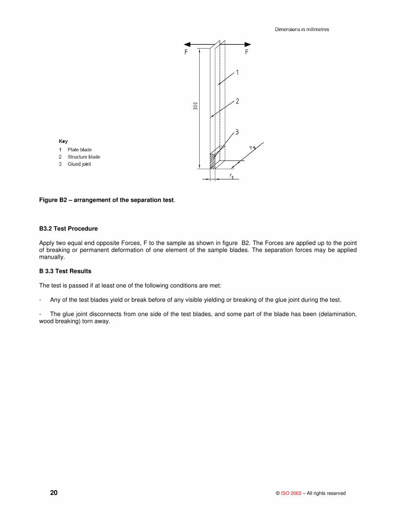
Figure B2 – arrangement of the separation test.
B3.2 Test Procedure
Apply two equal end opposite Forces, F to the sample as shown in figure B2. The Forces are applied up to the point of breaking or permanent deformation of one element of the sample blades. The separation forces may be applied manually.
B 3.3 Test Results
The test is passed if at least one of the following conditions are met:
- Any of the test blades yield or break before of any visible yielding or breaking of the glue joint during the test.
- The glue joint disconnects from one side of the test blades, and some part of the blade has been (delamination, wood breaking) torn away.

© ISO 2002 – All rights reserved 21
ANNEX C (Normative)
Unsupported plate dimensions
For rectangular plate, the small and large unsupported dimensions are b and a respectively, as shown in figure C.1a). For a folded plate, the small and large unsupported dimensions are b and a respectively, as shown in figure C.1.c. For a circular plate, the unsupported diameter is d, as shown in figure C.1 b). For non-rectangular or non circular plate shapes, use “equivalent” dimensions of a rectangular or circular plate having an area equal to the plate being considered (see Figure C.2).
Figure C.1 – Unsupported Plate Dimensions

22 © ISO 2002 – All rights reserved
Figure C.2 – Equivalent Dimensions.

© ISO 2002 – All rights reserved 23
BIBLIOGRAPHY
(1) International convention on Load lines, Geneva 1966 (ICLL)
.

FORM 6 (ISO) Page 1 of 5 Version 2001-07
RESULT OF VOTING ON NEW WORK ITEM PROPOSAL
Date 2006-10-02 ISO/TC 8 / SC 1 N 205
Title of TC/SC concerned SC 1 - Lifesaving and Fire Protection
To be completed by the secretariat and sent to the ISO Central Secretariat and to all P- and O-members of the TC or SC concerned, with a copy to the TC secretariat in the case of a subcommittee.
Proposal ISO/TC 8/SC 1 N 203 Circulation 2006-05-19 Deadline 2006-08-19
Title (new title if appropriate; French title to be indicated in all cases, even when no French version is envisaged) English title Ships and marine technology - Large yachts - Strength and watertightness
of windows and portlights French title
Results (the compilation of results is given as an annex)
The following criteria for acceptance have been met: Average points (y/x) awarded by P-members for market relevance greater than 15 Approval by a simple majority of the voting P-members 5 or more P-members voting approval have agreed to participate in the development of the project and have nominated
an expert
The proposal is therefore: Approved (all approval criteria met) Not approved (one or more approval criteria not met)
Associated draft no draft was associated with this ballot. A first draft is expected by (give date) the associated draft is adopted as a working draft (WD) the associated draft is approved as a Committee draft (CD) the associated draft is approved as the proposed Draft International Standard (DIS)
Further procedures (attribution to TC/SC/WG, Project Leader, development procedure, meetings, etc.) The project is to be first registered as a Preliminary Work Item (stage 10.00) The project is to be immediately registered as an active work item
Other: New work item to be registered to new TC 8/SC 12
Experts (give details below, or as a separate annex) See annex
Documents to be considered (give details below, or as a separate annex)
as a CD: 2007-09-30 as a FDIS: 2009-06-30 Target date for submission: as a DIS: 2008-09-30 for publication: 2009-09-30
Secretariat Secretary Registration by the Central Secretariat ANSI
Kurt J. Heinz, P.E.
Date
Allocated project number
Other information, comments, etc. appended
See comments at Annex.

Result of voting on new work item proposal
FORM 6 (ISO) Page 2 of 5
Compilation of the results of voting on ISO/NP Ships and marine technology – Large yachts – Strength and watertightness of windows and portlights
Mem
ber
stat
us
Eval
uatio
n
Just
ifica
tion
Vote
Part
icip
atio
n
Expe
rt(s
) no
min
ated
App
rova
l +
Part
.+N
omin
.
Acc
epte
d as
CD
Acc
epte
d as
DIS
Com
men
ts
encl
osed
no re
ply
(opt
iona
l)
Q. 2 Q. 3.1 Q. 3.2 3.1+ 3.2 Q. 3.3
Member body
P/O Points Y/N Yes No Abst. Y/N Y/N Y/N Y/N Y/N JISC/JSTRA – Japan P - - X BIS - India P 17 Y X Y Y Y Y Y ANSI – USA P 21 Y X Y Y Y N N DIN – Germany P 8 N X Y Y N N N BSI – UK P 18 Y X Y Y Y Y N DSSU – Ukraine P 20 Y X N N N N Y CSSC – China P 20 Y X Y Y Y Y N NEN – Netherlands P X UNI – Italy P 25 Y X Y Y Y N N
Totals (P-members only) 129 6Y 6 1 2 6 6 5 2 2 1
Abstentions and incomplete votes are not counted
Total number of points awarded by voting P-members (y): 129
Total of P-members voting (x): 7
Average points per P-member voting (y/x): 18.5

Result of voting on new work item proposal
FORM 6 (ISO) Page 3 of 5
ANNEX 1
Nominated experts
[email protected] (Nik Parker)
[email protected] (Thomas Marhevko)
[email protected], [email protected] (S. Chakrabartty)
[email protected] (Guglielmo Macrelli)
[email protected] (Zhang Meiling)

Template for comments and secretariat observations Date: 2006-10-02 Document: ISO/TC8/SC1 N 205 1 2 (3) 4 5 (6) (7)
MB1
Clause No./ Subclause No./
Annex (e.g. 3.1)
Paragraph/ Figure/Table/
Note (e.g. Table 1)
Type of
com-ment2
Comment (justification for change) by the MB Proposed change by the MB Secretariat observations on each comment submitted
1 MB = Member body (enter the ISO 3166 two-letter country code, e.g. CN for China; comments from the ISO/CS editing unit are identified by **) 2 Type of comment: ge = general te = technical ed = editorial NOTE Columns 1, 2, 4, 5 are compulsory.
page 4 of 5 ISO electronic balloting commenting template/version 2001-10
DE 2 ge for chemically toughened glass insert EN 12337-1
DE 2 ge for heading glass insert ISO 3434
DE all ge normally the term "glass panels" instead of "plates" is used delete: plates, insert: glass panels
DE 3.3 te definition portlight shall described accurately for instance: surface glass up to 0,166 m2
DE 3.4 te definition deadlight should ristricted for instance: metallic closing equipment…
DE 3.12 te water tightness is defined in ISO 1751 and ISO 3903
delete text and insert: see ISO 1751 and ISO 3903
DE 3.19.8 te normally the term "hardening depth" instead of "Case depth" is used delete: case depth, insert: hardening depth
DE 5.2 te design pressure acc. to ISO 5779 and ISO 5780
DE 5.3 te water tightness test procedure is part of ISO 1751 and ISO 3903 deleted the last sentence
DE 8.1 ge this is defined in ISO 21005 and ISO 3903 delete the text and insert "see ISO 21005 and ISO 3903"
DE 8.2 ge this is defined in ISO 21005 and ISO 3903 delete the text and insert "see ISO 21005 and ISO 3903"
DE 8.3 te this is defined in ISO 5779 and ISO 5780 delete the text and insert "see ISO 5779 and ISO 5780"
DE 8.5 table 3 te the title should be described the tenor more accurately delete: materials, insert: glass
DE 8.7 te polycarbonate is to be avoided because of the high different thermal expansion omit polycarbonate
DE 8.8 ge IGU is not defined Please defined IGU

Template for comments and secretariat observations Date: 2006-10-02 Document: ISO/TC8/SC1 N 205 1 2 (3) 4 5 (6) (7)
MB1
Clause No./ Subclause No./
Annex (e.g. 3.1)
Paragraph/ Figure/Table/
Note (e.g. Table 1)
Type of
com-ment2
Comment (justification for change) by the MB Proposed change by the MB Secretariat observations on each comment submitted
1 MB = Member body (enter the ISO 3166 two-letter country code, e.g. CN for China; comments from the ISO/CS editing unit are identified by **) 2 Type of comment: ge = general te = technical ed = editorial NOTE Columns 1, 2, 4, 5 are compulsory.
page 5 of 5 ISO electronic balloting commenting template/version 2001-10
DE Annex A te it is part of ISO 1751 and ISO 3903 delete
DE Annex B B2.1 te the glass-pane shall dbe held by a metallic frame
DE Annex B B2.1 te outside and inside should be mentioned
DE Annex B B2.1 te no metallic hold of the glass pane overlap of the glass width 30 mm
thickness of the glue 6 – 8 mm