Embed Size (px)
Citation preview

International Journal Of Advancement In Engineering Technology, Management and Applied
Science (IJAETMAS)
ISSN: 2349-3224 || www.ijaetmas.com || Volume 03 - Issue 09 || September - 2016 || PP. 74-89
www.ijaetmas.com Page 74
FORMING AND SHAPING OF PLASTIC MATERIALS BY USING
CNC MACHINES
*K.Siva Kishore Babu,
1B.Koteswararao
#,1P.S.Prema Kumar
$
1,#,$Assistant professor,k.L.University,Greenfields,Guntur-522502.
ABSTRACT
Plastics can be processed in many ways of which INJECTION MOLDING and BLOW
MOLDING are the most widely used and versatile processing technique. The process is known
for it’s high production rate, lower labor costs repeatability and it’s ability to produce finished
components with a large variety of materials. In multiple cavity moulds one of the major
concerns when the size of the component is small is the material wastage in the form of
“RUNNER”. In this dissertation efforts have been made to design a 16 cavity mould for arc
guide plate cover as per the component requirement based on a runner layout with least runner
length. Runner sizes for different branches of the feed systems are obtained from empirical
relations. The sixteen components are imported and meshed in mould flow analysis software and
the feed system is modeled. The combination is then checked and analyzed using mould flow
insight. The analysis is run again varying runner sizes violating the empirical guidelines an
attempt to save material. The optimum runner size is determined when no further reduction of
the runner size is possible without compromising the smooth running of the mould. The
injection mould is then modified to incorporate the optimized feed system. Temperature at flow
front, weld line and maximum clamping force, cavity pressure are also observed in addition to
runner optimization. The designer’s intent is then specified through 2D drawings of the part
forming inserts and tool assembly. The amount of savings per annum is then calculated based on
the difference in weight of the feed system before and after analysis which amounts to 95% of
the tool cost.
Introduction 1.1 History
1847 Jons Jacob Berzelius produces first condensation polymer, polyester, from glycerin
(propanetriol) and tartaric acid Jons Jacob Berzelius is also credited with originating the
chemical terms "catalysis," "polymer," "isomer," and "allotrope," although his original
definitions differ dramatically from modern usage. For example, he coined the term "polymer" in
1833 to describe organic compounds which shared identical empirical formulas but which
differed in overall molecular weight, the larger of the compounds being described as "polymers"
of the smallest. According to this (now obsolete) definition, glucose (C6H12O6) would be a
polymer of formaldehyde (CH2O).The first man-made commercial plastic was invented in
Britain in 1861 by Alexander Parkes. He publicly demonstrated it at the 1862 International
Exhibition in London, calling the material he produced "Parkesine." Derived from cellulose,
Parkesine could be heated, molded, and retain its shape when cooled. It was, however, expensive
to produce, prone to cracking, and highly flammable.In 1868, American inventor John Wesley
Hyatt developed a plastic material he named Celluloid, improving on Parkes' invention so that it
could be processed into finished form. Together with his brother Isaiah, Hyatt patented the first

International Journal Of Advancement In Engineering Technology, Management and Applied
Science (IJAETMAS)
ISSN: 2349-3224 || www.ijaetmas.com || Volume 03 - Issue 09 || September - 2016 || PP. 74-89
www.ijaetmas.com Page 75
injection molding machine in 1872. This machine was relatively simple compared to machines in
use today. It worked like a large hypodermic needle, using a plunger to inject plastic through a
heated cylinder into a mold. The industry progressed slowly over the years, producing products
such as collar stays, buttons, and hair combs.The plastic injection molding industry has evolved
over the years from producing combs and buttons to producing a vast array of products for many
industries including automotive, medical, aerospace, consumer products, toys, plumbing,
packaging, and construction.
1.2.BPA controversy
Some polymers may also decompose into the monomers or other toxic substances when
heated. In 2011, it was reported that "almost all plastic products" sampled released chemicals
with estrogenic activity, although the researchers identified plastics which did not leach
chemicals with estrogenic activity. The primary building block of polycarbonates, bisphenol A
(BPA), is an estrogen-like endocrine disruptor that may leach into food. Research in
Environmental Health Perspectives finds that BPA leached from the lining of tin cans, dental
sealants and polycarbonate bottles can increase body weight of lab animals' offspring. A more
recent animal study suggests that even low-level exposure to BPA results in insulin resistance,
which can lead to inflammation and heart disease. As of January 2010, the LA Times newspaper
reports that the United States FDA is spending $30 million to investigate indications of BPA
being linked to cancer. Bis(2-ethylhexyl) adipate, present in plastic wrap based on PVC, is also
of concern, as are the volatile organic compounds present in new car smell. The European Union
has a permanent ban on the use of phthalates in toys. In 2009, the United States government
banned certain types of phthalates commonly used in plastic.
1.3 Environmental issues
Plastics are durable and degrade very slowly; the chemical bonds that make plastic so
durable make it equally resistant to natural processes of degradation. Since the 1950s, one billion
tons of plastic have been discarded and may persist for hundreds or even thousands of years.
Perhaps the biggest environmental threat from plastic comes from nurdles, which are the raw
material from which all plastics are made. They are tiny pre-plastic pellets that kill large numbers
of fish and birds that mistake them for food.Prior to the ban on the use of CFCs in extrusion of
polystyrene (and general use, except in life-critical fire suppression systems; see Montreal
Protocol), the production of polystyrene contributed to the depletion of the ozone layer; however,
non-CFCs are currently used in the extrusion process.
1.4 Incineration of plastics
Plastics can be converted into a fuel since they are usually hydrocarbon-based and can be
broken down into liquid hydrocarbon. One kilogram of waste plastic produces a liter of
hydrocarbon. In some cases, burning plastic can release toxic fumes. Burning the plastic
polyvinyl chloride (PVC) may create dioxin.
1.5.Recycling
Thermoplastics can be remolded and reused, and thermoset plastics can be ground up and
used as filler, although the purity of the material tends to degrade with each reuse cycle. There
are methods by which plastics can be broken back down to a feedstock state.The greatest
challenge to the recycling of plastics is the difficulty of automating the sorting of plastic wastes,
making it labor intensive. Typically, workers sort the plastic by looking at the resin identification

International Journal Of Advancement In Engineering Technology, Management and Applied
Science (IJAETMAS)
ISSN: 2349-3224 || www.ijaetmas.com || Volume 03 - Issue 09 || September - 2016 || PP. 74-89
www.ijaetmas.com Page 76
code, although common containers like soda bottles can be sorted from memory. Typically, the
caps for PETE bottles are made from a different kind of plastic which is not recyclable, which
presents additional problems to the automated sorting process. Other recyclable materials such as
metals are easier to process mechanically. However, new processes of mechanical sorting are
being developed to increase capacity and efficiency of plastic recycling.While containers are
usually made from a single type and color of plastic, making them relatively easy to be sorted, a
consumer product like a cellular phone may have many small parts consisting of over a dozen
different types and colors of plastics. In such cases, the resources it would take to separate the
plastics far exceed their value and the item is discarded. However, developments are taking place
in the field of active disassembly, which may result in more consumer product components being
re-used or recycled. Recycling certain types of plastics can be unprofitable, as well. For example,
polystyrene is rarely recycled because it is usually not cost effective. These unrecycled wastes
are typically disposed of in landfills, incinerated or used to produce electricity at waste-to-energy
plants.A first success in recycling of plastics is Vinyloop, a recycling process and an approach of
the industry to separate PVC from other materials through a process of dissolution, filtration and
separation of contaminations. A solvent is used in a closed loop to elute PVC from the waste.
This makes it possible to recycle composite structure PVC waste which normally is being
incinerated or put in a landfill. Vinyloop-based recycled PVC's primary energy demand is 46
percent lower than conventional produced PVC. The global warming potential is 39 percent
lower. This is why the use of recycled material leads to a significant better ecological footprint.
In 1988, to assist recycling of disposable items, the Plastic Bottle Institute of the Society of the
Plastics Industry devised a now-familiar scheme to mark plastic bottles by plastic type. A plastic
container using this scheme is marked with a triangle of three "chasing arrows", which encloses a
number giving the plastic type:
1. PET (PETE), polyethylene terephthalate
2. HDPE, high-density polyethylene
3. PVC, polyvinyl chloride
4. LDPE, low-density polyethylene,
5. PP, polypropylene
6. PS, polystyrene
7. Other types of plastics
2.PROCESSING METHODS
Molding or moulding is the process of manufacturing by shaping pliable raw material
using a rigid frame or model called a pattern. A mold or mould is a hollowed-out block that is
filled with a liquid like plastic, glass, metal, or ceramic raw materials. The liquid hardens or sets
inside the mold, adopting its shape. A mold is the counterpart to a cast. The manufacturer who
makes the molds is called the mold maker. A release agent is typically used to make removal of
the hardened/set substance from the mold easier. Typical uses for molded plastics include
molded furniture, molded household goods, molded cases, and structural materials.

International Journal Of Advancement In Engineering Technology, Management and Applied
Science (IJAETMAS)
ISSN: 2349-3224 || www.ijaetmas.com || Volume 03 - Issue 09 || September - 2016 || PP. 74-89
www.ijaetmas.com Page 77
Fig .1: One half of a bronze mold for casting dated to the period 1400-1000 BC.
Fig 2: Stone mold of the Bronze Age used to produce spear tips.
3. TYPES OF MOLDING
Blow molding
Compaction plus sintering
Compression molding
Expandable bead molding
Extrusion molding
Foam molding
Injection molding
Laminating
Reaction injection molding
Matched mold
Matrix molding
Plastic moulding
Pressure plug assist molding
Rotational molding (or Rotomolding)
Transfer molding
Thermoforming
Vacuum forming, a simplified version of thermoforming
Vacuum plug assist molding
3.1 Die (manufacturing)
A die is a specialized tool used in manufacturing industries to cut or shape material using
a press. Like molds, dies are generally customized to the item they are used to create. Products
made with dies range from simple paper clips to complex pieces used in advanced technology.

International Journal Of Advancement In Engineering Technology, Management and Applied
Science (IJAETMAS)
ISSN: 2349-3224 || www.ijaetmas.com || Volume 03 - Issue 09 || September - 2016 || PP. 74-89
www.ijaetmas.com Page 78
Fig 3:Injection molding mold.
Forming dies are typically made by tool and die makers and put into production after
mounting into a press. The die is a metal block that is used for forming materials like sheet metal
and plastic. For the vacuum forming of plastic sheet only a single form is used, typically to form
transparent plastic containers (called blister packs) for merchandise. Vacuum forming is
considered a simple molding thermoforming process but uses the same principles as die forming.
For the forming of sheet metal, such as automobile body parts, two parts may be used, one,
called the punch, performs the stretching, bending, and/or blanking operation, while another part,
called the die block, securely clamps the workpiece and provides similar, stretching, bending,
and/or blanking operation. The workpiece may pass through several stages using different tools
or operations to obtain the final form. In the case of an automotive component there will usually
be a shearing operation after the main forming is done and then additional crimping or rolling
operations to ensure that all sharp edges are hidden and to add rigidity to the panel.
3.2 Die components
The main components for Die Tool sets are:
Die block - This is the main part that all the other parts are attached to.
Punch plate - This part holds and supports the different punches in place.
Blank punch - This part along with the Blank Die produces the blanked part.
Pierce punch - This part along with the Pierce Die removes parts from the blanked
finished part.
Stripper plate - This is used to hold the material down on the Blank/ Pierce Die and strip
the material off the punches.
Pilot - This is used to keep the material being worked on in position.
Guide / Back gage / Finger stop - These parts are all used to make sure that the material
being worked on always goes in the same position, within the die, as the last one.
Setting (Stop) Block - This part is used to control the depth that the punch goes into the
die.

International Journal Of Advancement In Engineering Technology, Management and Applied
Science (IJAETMAS)
ISSN: 2349-3224 || www.ijaetmas.com || Volume 03 - Issue 09 || September - 2016 || PP. 74-89
www.ijaetmas.com Page 79
Blanking Dies - See Blanking Punch
Pierce Die - See Pierce Punch.
shank-used to hold in the presses. it should be align and situated at the center of gravity
of the plate. 4.INJECTION MOLDING
Injection molding is the most commonly used manufacturing process for the fabrication
of plastic parts. A wide variety of products are manufactured using injection molding, which
vary greatly in their size, complexity, and application. The injection molding process requires the
use of an injection molding machine, raw plastic material, and a mold. The plastic is melted in
the injection molding machine and then injected into the mold, where it cools and solidifies into
the final part. The steps in this process are described in greater detail in the next section.
Fig 4:Injection molding overview.
Injection molding is used to produce thin-walled plastic parts for a wide variety of
applications, one of the most common being plastic housings. Plastic housing is a thin-walled
enclosure, often requiring many ribs and bosses on the interior. These housings are used in a
variety of products including household appliances, consumer electronics, power tools, and as
automotive dashboards.
4.1 Process cycle
The process cycle for injection molding is very short, typically between 2 seconds and 2
minutes, and consists of the following four stages:
1. Clamping
2. Injection
3. Cooling
4. Ejection

International Journal Of Advancement In Engineering Technology, Management and Applied
Science (IJAETMAS)
ISSN: 2349-3224 || www.ijaetmas.com || Volume 03 - Issue 09 || September - 2016 || PP. 74-89
www.ijaetmas.com Page 80
Fig 5:Injection molded part.
4.2 Equipments
Injection molding machines have many components and are available in different
configurations, including a horizontal configuration and a vertical configuration. However,
regardless of their design, all injection molding machines utilize a power source, injection unit,
mold assembly, and clamping unit to perform the four stages of the process cycle.
4.3.Injection unit
The injection unit is responsible for both heating and injecting the material into the mold.
The first part of this unit is the hopper, a large container into which the raw plastic is poured. The
hopper has an open bottom, which allows the material to feed into the barrel. The barrel contains
the mechanism for heating and injecting the material into the mold. This mechanism is usually a
ram injector or a reciprocating screw. A ram injector forces the material forward through a
heated section with a ram or plunger that is usually hydraulically powered. Today, the more
common technique is the use of a reciprocating screw. A reciprocating screw moves the material
forward by both rotating and sliding axially, being powered by either a hydraulic or electric
motor. The material enters the grooves of the screw from the hopper and is advanced towards the
mold as the screw rotates. While it is advanced, the material is melted by pressure, friction, and
additional heaters that surround the reciprocating screw. The molten plastic is then injected very
quickly into the mold through the nozzle at the end of the barrel by the buildup of pressure and
the forward action of the screw.
4.4.Clamping unit
Prior to the injection of the molten plastic into the mold, the two halves of the mold must
first be securely closed by the clamping unit. When the mold is attached to the injection molding
machine, each half is fixed to a large plate, called a platen. The front half of the mold, called the
mold cavity, is mounted to a stationary platen and aligns with the nozzle of the injection unit.
The rear half of the mold, called the mold core, is mounted to a movable platen, which slides
along the tie bars. The hydraulically powered clamping motor actuates clamping bars that push
the moveable platen towards the stationary platen and exert sufficient force to keep the mold
securely closed while the material is injected and subsequently cools. After the required cooling
time, the mold is then opened by the clamping motor. An ejection system, which is attached to
International Journal Of Advancement In Engineering Technology, Management and Applied
Science (IJAETMAS)
ISSN: 2349-3224 || www.ijaetmas.com || Volume 03 - Issue 09 || September - 2016 || PP. 74-89
www.ijaetmas.com Page 81
the rear half of the mold, is actuated by the ejector bar and pushes the solidified part out of the
open cavity.
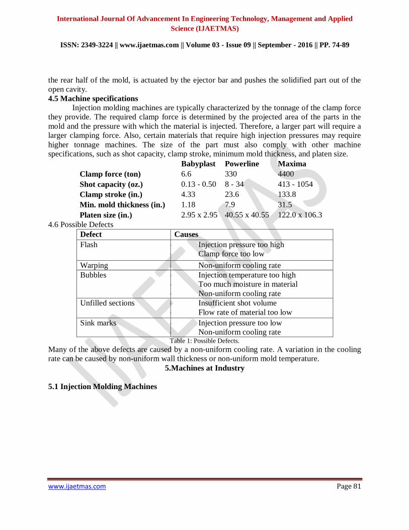
4.5 Machine specifications
Injection molding machines are typically characterized by the tonnage of the clamp force
they provide. The required clamp force is determined by the projected area of the parts in the
mold and the pressure with which the material is injected. Therefore, a larger part will require a
larger clamping force. Also, certain materials that require high injection pressures may require
higher tonnage machines. The size of the part must also comply with other machine
specifications, such as shot capacity, clamp stroke, minimum mold thickness, and platen size.
Babyplast Powerline Maxima
Clamp force (ton) 6.6 330 4400
Shot capacity (oz.) 0.13 - 0.50 8 - 34 413 - 1054
Clamp stroke (in.) 4.33 23.6 133.8
Min. mold thickness (in.) 1.18 7.9 31.5
Platen size (in.) 2.95 x 2.95 40.55 x 40.55 122.0 x 106.3
4.6 Possible Defects
Defect Causes
Flash Injection pressure too high
Clamp force too low
Warping Non-uniform cooling rate
Bubbles Injection temperature too high
Too much moisture in material
Non-uniform cooling rate
Unfilled sections Insufficient shot volume
Flow rate of material too low
Sink marks Injection pressure too low
Non-uniform cooling rate Table 1: Possible Defects.
Many of the above defects are caused by a non-uniform cooling rate. A variation in the cooling
rate can be caused by non-uniform wall thickness or non-uniform mold temperature.
5.Machines at Industry
5.1 Injection Molding Machines

International Journal Of Advancement In Engineering Technology, Management and Applied
Science (IJAETMAS)
ISSN: 2349-3224 || www.ijaetmas.com || Volume 03 - Issue 09 || September - 2016 || PP. 74-89
www.ijaetmas.com Page 82
Fig 6: SW-B series (SW-90B ~ SW-320B).
SW-B series Plastic Injection Molding Machine is equipping a five-point toggle
mechanism and differential hydraulic circuit to substantially accelerate forming speed, increase
forming rate and reduce cycle time of production. The clamping, ejecting and injection units use
linear transducers to control movement stroke of each function precisely. Multiple pressure,
speed, time and position controls of machinery performances aim for saving power and
achieving accuracy of finished articles. Usage of double injection cylinder is to shorten injection
stroke as well as to avoid material leakage.
In addition, SW-B series keeps improving on quality and functions. Some
advanced mechanical applications such as power-saving variable pump, closed-loop hydraulic
circuit, double (triple) independent hydraulic circuits and high-speed injection, accumulator
injection etc. are able to be installed on B series, to satisfy the demand of higher production and
lower cost from customer.
Specifications
MODEL UNIT SW-90B SW-120B
Injection Unit
Screw Diameter mm 32 36
Injection pressure kg/cm2 2297 2177
Theoretical shot Volume cm3 145 204
Shot Weight(PS) oz 122 171
Injection Rate cm3/sec 65 84
Plasticizing Capacity(PS) Kg/hr 37 47
Theoretical Screw Revolution 0-200 0-200
Injection Stroke mm 180 200
Clamping Unit
Clamping Force ton 90 120
Max Opening Daylight mm 730 820
Space Between Tie Bars mm 360*360 395*395
International Journal Of Advancement In Engineering Technology, Management and Applied
Science (IJAETMAS)
ISSN: 2349-3224 || www.ijaetmas.com || Volume 03 - Issue 09 || September - 2016 || PP. 74-89
www.ijaetmas.com Page 83
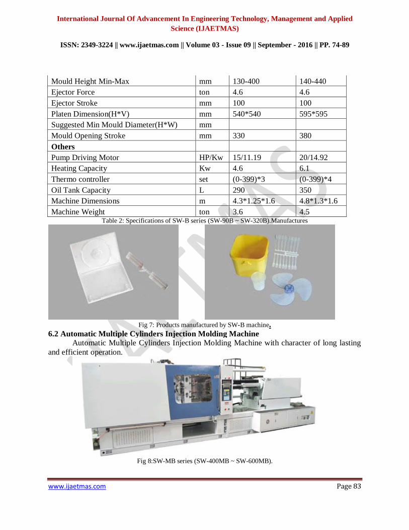
Mould Height Min-Max mm 130-400 140-440
Ejector Force ton 4.6 4.6
Ejector Stroke mm 100 100
Platen Dimension(H*V) mm 540*540 595*595
Suggested Min Mould Diameter(H*W) mm
Mould Opening Stroke mm 330 380
Others
Pump Driving Motor HP/Kw 15/11.19 20/14.92
Heating Capacity Kw 4.6 6.1
Thermo controller set (0-399)*3 (0-399)*4
Oil Tank Capacity L 290 350
Machine Dimensions m 4.3*1.25*1.6 4.8*1.3*1.6
Machine Weight ton 3.6 4.5 Table 2: Specifications of SW-B series (SW-90B ~ SW-320B).Manufactures
Fig 7: Products manufactured by SW-B machine.
6.2 Automatic Multiple Cylinders Injection Molding Machine
Automatic Multiple Cylinders Injection Molding Machine with character of long lasting
and efficient operation.
Fig 8:SW-MB series (SW-400MB ~ SW-600MB).

International Journal Of Advancement In Engineering Technology, Management and Applied
Science (IJAETMAS)
ISSN: 2349-3224 || www.ijaetmas.com || Volume 03 - Issue 09 || September - 2016 || PP. 74-89
www.ijaetmas.com Page 84
SW-MB series automatic multiple cylinders injection molding machine particularly
focuses on customers using middle and large model machineries, ranging from 400 tons to 2300
tons clamping force. Instead of equipping double toggle mechanism, MB series uses four locking
mechanisms to place exact position of moving platen and meanwhile generates clamping force
by four hydraulic cylinders. The design of multiple cylinders could reduce total machinery
length, as well as provide more than twice mold opening stroke in contract with toggle injection
machine. MB series is the most appropriate model for producing longer or deeper articles. In
addition, new controller of MB series has 10.4 inches TFT-LCD monitor with 16.5 million
colors offering clear graphic display, particularly appropriate for a long-run use by operator. It
possesses several language modes that could be switched immediately to support personnel of
different regions. In addition, it installs many technical applications, such as data-printing, USB
port, Ethernet (optional) and touch panel (optional) to be run more efficiently by operators.
Manufactures
Fig 9: Products manufactured by SW-MB machine.
Specifications
MODEL UNIT SW-400MB
Injection Unit
Screw Diameter mm 65
Injection pressure kg/cm2 1850
Theoretical shot Volume cm3 1128
Shot Weight(PS) oz 33.4
Injection Rate cm3/sec 288
Plasticizing Capacity(PS) Kg/hr 154
Injection Stroke mm 340
Clamping Unit
Clamping Force ton 400
Max Opening Daylight mm 1750-950
Space Between Tie Bars mm 700*700
International Journal Of Advancement In Engineering Technology, Management and Applied
Science (IJAETMAS)
ISSN: 2349-3224 || www.ijaetmas.com || Volume 03 - Issue 09 || September - 2016 || PP. 74-89
www.ijaetmas.com Page 85
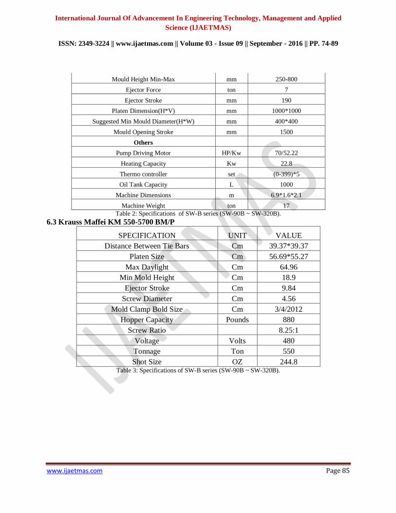
Mould Height Min-Max mm 250-800
Ejector Force ton 7
Ejector Stroke mm 190
Platen Dimension(H*V) mm 1000*1000
Suggested Min Mould Diameter(H*W) mm 400*400
Mould Opening Stroke mm 1500
Others
Pump Driving Motor HP/Kw 70/52.22
Heating Capacity Kw 22.8
Thermo controller set (0-399)*5
Oil Tank Capacity L 1000
Machine Dimensions m 6.9*1.6*2.1
Machine Weight ton 17
Table 2: Specifications of SW-B series (SW-90B ~ SW-320B).
6.3 Krauss Maffei KM 550-5700 BM/P
SPECIFICATION UNIT VALUE
Distance Between Tie Bars Cm 39.37*39.37
Platen Size Cm 56.69*55.27
Max Daylight Cm 64.96
Min Mold Height Cm 18.9
Ejector Stroke Cm 9.84
Screw Diameter Cm 4.56
Mold Clamp Bold Size Cm 3/4/2012
Hopper Capacity Pounds 880
Screw Ratio
8.25:1
Voltage Volts 480
Tonnage Ton 550
Shot Size OZ 244.8 Table 3: Specifications of SW-B series (SW-90B ~ SW-320B).

International Journal Of Advancement In Engineering Technology, Management and Applied
Science (IJAETMAS)
ISSN: 2349-3224 || www.ijaetmas.com || Volume 03 - Issue 09 || September - 2016 || PP. 74-89
www.ijaetmas.com Page 86
Fig 10: Krauss Maffei KM 550-5700 BM/P.
6.4 ROCEE (RTD-250)
ROCEE supply RTD series economic injection machines and RTS series precise
injection machines.RTD series machine installed with double cylinder injection unit. It can be
used for most of plastic injection applications.
Fig 11: ROCEE (RTD-250).
Specification
Hydraulics
◆ Pump/Motor
6-pole motor for low noise and longer pump life
Low speed pump for low noise and long life
◆ Oil Filter – Externally Mounted Suction Filter
For easy access and filter clean or filter change
With shut off check valve, if filter element removed
◆ Oil Tank
Oil level indicator
Oil temperature sensor and alarm on control
External heat exchanger
Machine Safety
◆ Nozzle purge guard- with limit switch

International Journal Of Advancement In Engineering Technology, Management and Applied
Science (IJAETMAS)
ISSN: 2349-3224 || www.ijaetmas.com || Volume 03 - Issue 09 || September - 2016 || PP. 74-89
www.ijaetmas.com Page 87
◆ Hydraulic guard interlock – for front and rear moving guards
◆ Electric interlock – for front and rear guards
◆ Oil temperature and level indicator
◆ Low pressure mould protection
◆ Automatic lubrication – with fail safe alarm
Controls ◆ TECH688A controller, with 8 inch LCD COLOUR screen, touch pad data-entry
◆ User-friendly and easy operation interface
◆ Fault diagnostics with plain text messages
◆ Control cabinet with cooling fans
◆ 4 x mould closing speeds
◆ 4 x mould opening speeds
◆ 6 x stage injection control (speed, position & pressure).
◆ 3 x stage screw recovery speeds
Optional Features ◆ Variable pumping system
◆ RFV precise injection system
◆ Special screw geometry
◆ Bimetal screws and barrels
◆ Shut-off nozzles
◆ Drop chute with photocell
Working of CNC Machines Computerized Numerical Control(CNC) machine works depends upon command given
and those commands are classified into two types they are G codes and M codes. Some of the G
codes and M codes are as follows
7.1 G codes
Special characters that can be used from within your program are:
G00 Rapid move
G01 Feed Rate move
G02 Clockwise move
G03 Counter Clockwise move
G04 Dwell time G04 L#
G08 Spline Smoothing On
G09 Exact stop check, Spline Smoothing Off
G10 A linear feedrate controlled move with a decelerated stop
G11 Controlled Decel stop
G17 XY PLANE
G18 XZ PLANE
G19 YZ PLANE
G28 Return to clearance plane
International Journal Of Advancement In Engineering Technology, Management and Applied
Science (IJAETMAS)
ISSN: 2349-3224 || www.ijaetmas.com || Volume 03 - Issue 09 || September - 2016 || PP. 74-89
www.ijaetmas.com Page 88
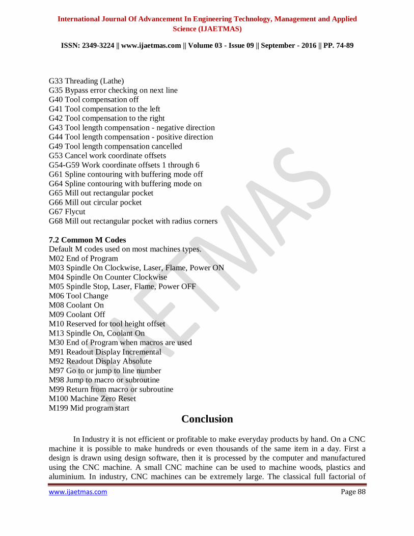
G33 Threading (Lathe)
G35 Bypass error checking on next line
G40 Tool compensation off
G41 Tool compensation to the left
G42 Tool compensation to the right
G43 Tool length compensation - negative direction
G44 Tool length compensation - positive direction
G49 Tool length compensation cancelled
G53 Cancel work coordinate offsets
G54-G59 Work coordinate offsets 1 through 6
G61 Spline contouring with buffering mode off
G64 Spline contouring with buffering mode on
G65 Mill out rectangular pocket
G66 Mill out circular pocket
G67 Flycut
G68 Mill out rectangular pocket with radius corners
7.2 Common M Codes Default M codes used on most machines types.
M02 End of Program
M03 Spindle On Clockwise, Laser, Flame, Power ON
M04 Spindle On Counter Clockwise
M05 Spindle Stop, Laser, Flame, Power OFF
M06 Tool Change
M08 Coolant On
M09 Coolant Off
M10 Reserved for tool height offset
M13 Spindle On, Coolant On
M30 End of Program when macros are used
M91 Readout Display Incremental
M92 Readout Display Absolute
M97 Go to or jump to line number
M98 Jump to macro or subroutine
M99 Return from macro or subroutine
M100 Machine Zero Reset
M199 Mid program start
Conclusion
In Industry it is not efficient or profitable to make everyday products by hand. On a CNC
machine it is possible to make hundreds or even thousands of the same item in a day. First a
design is drawn using design software, then it is processed by the computer and manufactured
using the CNC machine. A small CNC machine can be used to machine woods, plastics and
aluminium. In industry, CNC machines can be extremely large. The classical full factorial of

International Journal Of Advancement In Engineering Technology, Management and Applied
Science (IJAETMAS)
ISSN: 2349-3224 || www.ijaetmas.com || Volume 03 - Issue 09 || September - 2016 || PP. 74-89
www.ijaetmas.com Page 89
approach has been applied to the injection molding process to reduce the short-shot defect in
blade. Five controllable factors chosen forthe experiment are backpressure, holding pressure
transfer, spear temperature, manifold temperature, and screw rotation speed. The significant
factors for analysis A have been identified, and they were backpressure, backpressure × holding
pressure transfer, holding pressure transfer × spear temperature. Meanwhile for analysis B, the
significant factors were manifold temperature, backpressure × screw rotation speed, screw
rotation speed × holding pressure transfer, and backpressure × holding pressure transfer. The
verification experiments were conducted and the errors between the actual and predicted value of
blade weight were less than 2% and no short-shot defect was found.
Parts made from partially crystalline engineering polymers should preferably not be
made by hot runner injection molding if a perfect surface finish is essential. It is advisable to
make use of a subsidiary runner, which thermally isolates the nozzle from the molded part,
thereby reducing the risk of surface defects. The cold slug coming from the injection or hot
runner nozzle should be intercepted by a special device opposite the sprue so that it cannot get
into the molded part.
Bibliography Joining of Plastics, Handbook for Designers and Engineers Jordan Rotheiser
Bryce, Douglas M. Plastic Injection Molding: Manufacturing Process Fundamentals.
SME, 1996.
Callister, William D, Materials Science and Engineering: An Introduction, John Wiley
and Sons
Extrusion Blow Molding, Hanser-Gardner Publications.
Lee, Norman (1990), Plastic Blow Molding Handbook, Van Nostrand Reinhold.
Runner and Gating Design Handbook – Tools for Successful Injection Molding
By John P. Beaumont.
KOTESWARARAO.B
# was born in Yedlurupadu, India, in 1990. He received the B.Tech. Degree in Mechanical
Engineering from the JNTU Technological University Kakinada, India, in 2011, and the M.Tech. Degree in thermal
Engineering from the university college of Kakinada, India, in 2014.
From May 2011 to December 2012, he has been with the Department of mechanical Engineering, RVR Institute of
Engineering & Technology. Where he was an Assistant Professor. His current research interests include alternative
fuels, automobile emission reduction , and power plant optimization.