Embed Size (px)
DESCRIPTION
Formulations and Protocols for Electrophoresis and Western Blotting, continued There are two equations that have practical consequences in electrophoresis: Formulations and Protocols for Electrophoresis and Western Blotting, continued Tris base (12 mM) 1.45 g Glycine (96 mM) 7.2 g Methanol (20% final concentration) 200 ml DI Water add to 1.0 liter Total: 1.0 liter DI Water 760 ml Transfer Buffer (Cat. no. LC3675) 40 ml (undiluted at 25X concentration) Methanol 200 ml Total: 1000 ml
Citation preview

chapter 21 appendix
886 800 955 6288
applications and troubleshooting2
1.2
ap
pe
nd
ix
Important Licensing InformationThese products may be covered by one or more Limited Use Label Licenses (See Catalog number/Label License Index and Label Licenses in Appendix). By use of these products you acceptthe terms and conditions of all applicable Limited Use Label Licenses. All products are for research use only. CAUTION: Not intended for human or animal diagnostic or therapeutic uses.
Power Settings in Electrophoresis
There are two equations that have practical consequences in electrophoresis:
V = IR (Voltage = Current x Resistance)W = IV (Watts = Current x Voltage)
Resistance is determined by the number and thickness of thegels being run and the type of buffer being used. As the run pro-ceeds, fast moving, highly conductive chloride ions in the gel arereplaced by slower moving, less conductive ions from the run-ning buffer (such as glycine or tricine). This causes the resist-ance of the system to gradually increase as the run progresses.
Constant VoltageWe recommend a constant voltage setting for most applica-tions. There are two reasons for this: First, by using constantvoltage, both current and wattage will decrease as resistanceincreases (Figure 1). As per Ohms’ Law, the wattage (i.e., heat)will also decrease, providing a safety margin as the run pro-ceeds. Second, the same voltage setting can be used regardlessof the number of gels (or gel thickness) being run. This is notthe case when running a gel at constant current or wattage (seefollowing discussion).
Constant CurrentIf a constant current setting is used, as resistance increases duringthe run, voltage will increase to satisfy the requirement V=IR. If avoltage limit is not set and a local fault condition occurs, such as apoor connection, the voltage will increase sharply to compensatefor the very local high resistance (Figure 2). This can generateenough excess heat to severely damage the gel and the apparatus.If running under constant current conditions, it is essential to set avoltage limit on the power supply at, or slightly above, the maxi-mum voltage expected to be reached during the run.
Constant WattageIf constant wattage is used, the voltage will increase as currentdecreases, but the total amount of heat generated by the systemwill remain constant (Figure 3). However, should a local circuitmalfunction occur, localized high resistance could cause a high pro-portion of the total heat to be generated over a small distance. Ifusing a high voltage power supply without a set voltage limit, thiscould potentially cause serious damage to the apparatus and/or gel.
Power Considerations for BlottingSimilar electrical forces apply during transfer and separation.However, during blotting the distance that must be travelled (gelthickness) between electrodes is much less than during separa-tion, so lower voltage and lower field strength (volts/distance)are needed. On the other hand, the cross sectional area of cur-rent flow is much greater, so higher current is required.
Blotting power requirements depend on field strength (electrodesize) and conductivity of transfer buffer. The higher these are,the higher the current requirement will be, although throughoutthe run, current drops as the ions in the buffer polarize.Therefore it is important to ensure that the power supply beingused can accommodate the initial high current requirements. It isalso important to have a well rectified power supply whichensures power will flow unidirectionally. Any significant AC fluc-tuation will lead to corrosion of blotting electrodes.
Power Considerations for Isoelectric FocusingDuring isoelectric focusing, proteins migrate in an electric fielduntil a stable pH gradient is formed and proteins reach their pI.At that point, a high finishing voltage is applied to focus the pro-teins into very narrow zones. High voltage cannot be appliedduring the initial stages because the current created by themovement of the ampholytes leads to excessive heat generation.Alternatively, constant wattage can be applied and the voltagewill increase automatically as the current decreases.
Formulations and Protocols for Electrophoresis and Western Blotting, continued
At 125 volts constant, current andwattage decrease during the run.
At 2.5 watts constant, current decreases andvoltage increases throughout the run.
At 18 mAmps constant current, voltage andwattage increase throughout the run.
Figure 1 - Constant Voltage Figure 2 - Constant Current Figure 3 - Constant Wattage

appendixapplications and troubleshooting chapter 21a
pp
en
dix
21.2
Important Licensing InformationThese products may be covered by one or more Limited Use Label Licenses (See Catalog number/Label License Index and Label Licenses in Appendix). By use of these products you acceptthe terms and conditions of all applicable Limited Use Label Licenses. All products are for research use only. CAUTION: Not intended for human or animal diagnostic or therapeutic uses.
893 www.invitrogen.com
Formulations and Protocols for Electrophoresis and Western Blotting, continued
Gel Drying Tips for Pre-Cast Gels
Gels dried between cellophane sheets are ideal for permanent storage, fluorography, autoradiography, or photography. However, it can bea frustrating experience if your gels crack during the process. The following tips should be considered for drying the perfect gel.
Handle Gels with CareRemove the intact gel from the cassette. All edges should be as clean and straight as possible. Remove the stacking gel and wells. Slightnicks and tears can act as starting points for large cracks to develop. Use our gel knife or a razor blade to ensure all edges are straight.
Use a Gel Drying SolutionAfter staining and destaining the gel, perform three brief water rinses to stop the destaining process. Following this, equilibrate the gel in agel drying solution, such as Gel-Dry™ Drying Solution, on an orbital shaker for 10 minutes. Soak the gel-drying cellophane for 5 minutes.Most gel drying solutions contain an alcohol component to shrink the gel slightly and a glycerol component to regulate the rate of dryingand prevent over-dehydration. The Gel-Dry™ Drying Solution contains a proprietary non-glycerol component that regulates the rate of dryingand prevents cracks. If you do not have this solution, use a 20% methanol, 2% glycerol solution. Both of these solutions can be used withautoradiography and autoradiography signal enhancing solutions.
Note: Gels should not be soaked more than 10 minutes in an alcohol based drying solution. Alcohol will act as a destain causing bands to fade with extended soaking.
Remove Air BubblesAir bubbles trapped between the cellophane and gel act as starting points for cracks. Bubbles can be worked out toward the edge of the gel by rolling a pipette tip over the gel. Generous use of the drying solution may also help to remove bubbles.
Avoid Exposing Gel to a Heat SourceA passive drying system, such as the DryEase® Gel Drying System, allows for a slow and even rate of drying and takes approximately 48 hours to dry completely. Placing gels in a fume hood or near a heat source will increase the likelihood of the gels cracking. We recom-mend placing the gels in a cupboard to increase the humidity level slightly and consequently slow the rate of drying to ensure a crack-freegel.
Quick Fix for White BordersAfter a gel is dried, you may notice a white translucent border around the gel or white crystals forming on the surface of the gel. Theseare easily removed by wiping the gel with a damp laboratory wipe soaked with water or gel drying solution.

chapter 21 appendix
894 800 955 6288
applications and troubleshooting2
1.2
ap
pe
nd
ix
Important Licensing InformationThese products may be covered by one or more Limited Use Label Licenses (See Catalog number/Label License Index and Label Licenses in Appendix). By use of these products you acceptthe terms and conditions of all applicable Limited Use Label Licenses. All products are for research use only. CAUTION: Not intended for human or animal diagnostic or therapeutic uses.
Formulations and Protocols for Electrophoresis and Western Blotting, continued
Western Transfer Protocol
The following protocol is suitable for the majority of protein blotting applications using the XCell II™ blotting apparatus. For thebest results, some optimization by the user may be necessary(page xxx).
I. Required Materials:• XCell SureLock™ or XCell II™ Mini-Cell and Blot Module
(Cat. nos. EI0001, EI9001, and EI9051)• Previously electrophoresed mini-gels (maximum gel size
9 cm x 9 cm)• Pre-Cut Blotting Membranes:
Nitrocellulose (Cat. no. LC2000 or LC2001), PVDF (Cat. no. LC2002) or Nylon+ (Cat. no. LC2003)
• Blotting Pads (Cat. no. EI9052) • Methanol • DI water• Transfer Buffer (see below for formulation)• Shallow tray for equilibration of membranes, filter paper and
blotting pads
II. Specifications:
Cell dimensions: 14.5 cm x 14 cm x 11 cmBlot module capacity: Approx. 200 mlLower Buffer Chamber capacity: Approx. 600 mlBlot size: Approx. 9 cm x 9 cm
Note: During the following procedure, gloves should be worn at all times to prevent contamination of gels and membranes and exposure to irritants commonly used in electrophoresis and electrotransfer.
III. Preparation of Materials:a) Transfer Buffer–Please note that for most transfers the recom-
mended transfer buffer is a half-strength “Towbin” buffer, with20% methanol. The 1/2X Towbin provides enough ionicstrength for a successful transfer in the XCell II™ Blot Modulewithout generating excess heat. This buffer may not be appro-priate for use in other blotting units, and vice versa. Prepare one liter of transfer buffer (1/2X Towbin with 20% methanol)as follows:
Using our Tris-Glycine Transfer Buffer:
DI Water 760 mlTransfer Buffer (Cat. no. LC3675) 40 ml
(undiluted at 25X concentration)Methanol 200 mlTotal: 1000 ml
If preparing your own Tris-Glycine transfer buffer:
Tris base (12 mM) 1.45 gGlycine (96 mM) 7.2 gMethanol (20% final concentration) 200 mlDI Water add to 1.0 literTotal: 1.0 liter
Please see page xxx to prepare NuPAGE® transfer buffer.b) Prepare the blotting pads–Use about 700 ml of transfer buffer
to soak pads until saturated. Remove the air bubbles bysqueezing the pads while they are submerged in buffer.Removing air bubbles is essential as they can block the transfer of biomolecules if not removed.
c) Prepare the transfer membrane and filter paper–Cut selectedtransfer membrane and filter paper to the dimensions of the gel or use our pre-cut membrane/filter paper sandwiches.• PVDF membrane–Pre-wet PVDF membrane briefly in
methanol, ethanol, or isopropanol. Briefly rinse in DI water,then place in a shallow dish with 50-100 ml of transfer bufferfor several minutes.
• Nitrocellulose/Nylon membrane–Place directly into transfer buffer for several minutes.
• Filter paper–Soak briefly in transfer buffer immediately priorto use.
• Gel–The gel should be used immediately following the run,as discussed below. Do not soak the gel in transfer buffer.
IV. Assembling the Gel Membrane Sandwich:The gel membrane sandwich and blotting pads should be posi-tioned in the cathode core (-) of the blot module to fit horizontal-ly across the bottom of the unit. There should be a gap of approx-imately 1 cm at the top of the electrodes when the pads andassembly are in place (Figure 1).
Blotting pads assembled horizontally
1 cm
Figure 1 - Cathode core
appendixapplications and troubleshooting chapter 21a
pp
en
dix
21.2
Important Licensing InformationThese products may be covered by one or more Limited Use Label Licenses (See Catalog number/Label License Index and Label Licenses in Appendix). By use of these products you acceptthe terms and conditions of all applicable Limited Use Label Licenses. All products are for research use only. CAUTION: Not intended for human or animal diagnostic or therapeutic uses.
895 www.invitrogen.com
Formulations and Protocols for Electrophoresis and Western Blotting, continued
Western Transfer Protocol, continued
IV-A. Transferring One Gel1. Following electrophoresis, separate each of the three bonded
sides of the cassette by inserting the gel knife’s beveled edgeinto the gap between the cassette’s two plates. The notched(“well”) side of the cassette should face up. Push up anddown on the knife handle to separate the plates. Repeat oneach side of the cassette until the plates are completely sepa-rated. Please use caution when inserting the gel knifebetween the two plates to avoid excessive pressure towardsthe gel.
2. When opening the cassette, the gel may adhere to either sideof the cassette. Carefully remove and discard the plate with-out the gel, allowing the gel to remain on the other plate.Remove wells with the gel knife.
3. Place a piece of pre-soaked filter paper on top of the gel, justabove the “foot” at the bottom of the gel (leaving the “foot”of the gel uncovered). Keep the filter paper saturated withtransfer buffer and make sure all trapped air bubbles areremoved. This is easily done by using a glass pipette as aroller and gently rolling over the surface.
4. Turn the cassette over so gel and filter paper are facing downover a gloved hand or clean flat surface covered with a pieceof Parafilm® laboratory film. Remove the gel from the plateusing one of the following methods:a) If the gel rests on the longer (slotted) plate, use the gel
knife to push the foot out of the slot in the cassette andthe gel will then fall easily off the cassette plate.
b) If the gel rests on the shorter (notched) plate, use the gelknife to carefully loosen the bottom of the gel and allowthe gel to peel away from the plate.
5. When on a flat surface, cut the “foot” off the gel with the gel knife.6. Wet the surface of the gel with transfer buffer and position
the pre-soaked transfer membrane on the gel, ensuring all airbubbles have been removed.
7. Place the pre-soaked anode-side filter paper on top of the membrane. Remove any trapped air bubbles.
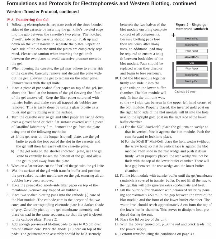
8. Place two soaked blotting pads into the cathode (-) core ofthe blot module. The cathode core is the deeper of the twocores and the corresponding electrode plate is a darker shadeof grey. Carefully pick up the gel membrane assembly andplace on pad in the same sequence, so that the gel is closestto the cathode plate (Figure 2).
9. Add enough pre-soaked blotting pads to rise to 0.5 cm overrim of cathode core. Place the anode (+) core on top of thepads. The gel/membrane assembly should be held securely
between the two halves of theblot module ensuring completecontact of all components.Because blotting pads losetheir resiliency after manyuses, an additional pad maybe required to ensure a snugfit between both sides of theblot module. Pads should bereplaced when they discolorand begin to lose resiliency.
10. Hold the blot module togetherfirmly and slide it into theguide rails on the lower bufferchamber. The blot module willonly fit into the unit one way,so the (+) sign can be seen in the upper left hand corner ofthe blot module. Properly placed, the inverted gold post onthe right hand side of the blot module will fit into the holenext to the upright gold post on the right side of the lowerbuffer chamber.
11. a) For the XCell SureLock™: place the gel tension wedge sothat its vertical face is against the blot module. Push thecam forward to lock into place.
b) For the XCell II™ Mini-Cell: place the front wedge (withoutthe screw hole) so that its vertical face is against the blotmodule. Then slide in the rear wedge and push it downfirmly. When properly placed, the rear wedge will not beflush with the top of the lower buffer chamber. There willbe a gap between the rear wedge and the lower bufferchamber.
12. Fill the blot module with transfer buffer until the gel/membranesandwich is covered in transfer buffer. Do not fill all the way tothe top: this will only generate extra conductivity and heat.
13. Fill the outer buffer chamber with deionized water by pour-ing approximately 650 ml in the gap between the front of theblot module and the front of the lower buffer chamber. Thewater level should reach approximately 2 cm from the top ofthe lower buffer chamber. This serves to dissipate heat pro-duced during the run.
14. Place the lid on top of the unit.15. With the power turned off, plug the red and black leads into
the power supply.16. Perform transfer using the conditions on page XX.
+Blotting Pad
Blotting Pad
GEL
Blotting Pad
Filter Paper
Blotting Pad
MEMBRANE
Filter Paper
Cathode (-) core
Figure 2 - Single gel membrane sandwich

chapter 21 appendix
896 800 955 6288
applications and troubleshooting2
1.2
ap
pe
nd
ix
Important Licensing InformationThese products may be covered by one or more Limited Use Label Licenses (See Catalog number/Label License Index and Label Licenses in Appendix). By use of these products you acceptthe terms and conditions of all applicable Limited Use Label Licenses. All products are for research use only. CAUTION: Not intended for human or animal diagnostic or therapeutic uses.
Formulations and Protocols for Electrophoresis and Western Blotting, continued
Western Transfer Protocol, continued
IV-B. Transferring Two Gels
1. Repeat steps 1–6 (IV-A) twiceto make two gel-membrane assemblies.
2. Place two pre-soaked pads oncathode shell of blot module.Place first gel-membraneassembly on pads in correctorientation, so gel is nearestcathode plate (Figure 3).
3. Add another pre-soaked blot-ting pad on top of first mem-brane assembly.
4. Position second gel-membraneassembly on top of blottingpad in the correct orientationso that the gel is nearest thecathode side.
5. Proceed with steps 8–13 listedunder “Transferring One Gel.”
Optimizing Your Western Transfer
Optimizing the Western transfer of proteins from SDS gelsrequires careful consideration of a number of parameters. The goal is to transfer all the protein out of the gel and have it transfer quantitatively to the transfer membrane. Achieving hightransfer efficiency requires a degree of optimization, particularlywhen both large and small proteins are involved.
Following transfer, little or no protein should remain in the gel.You can monitor this by simply staining the gel after it has beentransferred. The protein that has transferred out of the gel shouldbe visible primarily on the side of the membrane that contactsthe gel. If in doubt use a second “back up” membrane duringthe blot which you can stain afterwards to check for signs ofblow-through. If you find you have protein left in the gel andpoor membrane binding, consider adjusting the following parameters:
SDS vs AlcoholSDS and alcohol are used in most blotting protocols. However, theyhave opposing effects on the success of a transfer and need to beoptimized according to the nature of the proteins being transferred.
SDS is required for protein mobility and is particularly useful tofacilitate the transfer of large proteins out of the gel. However,since membrane binding requires hydrophobic interactions, toomuch SDS can prevent binding, especially to nitrocellulose. If too
much SDS is stripped from the protein it may not transfer out ofthe gel. As a general rule, if membrane binding appears to beefficient, but some protein remains in the gel, adding 0.01% SDSto the transfer buffer may promote complete transfer. The recom-mended protocol does not include SDS in the transfer buffer, butrequires that gels are not soaked in transfer buffer following elec-trophoresis; the residual SDS in the gel should be sufficient foran efficient transfer. Alcohol, on the other hand, is used toenhance hydrophobic binding of the protein to the membrane bystripping some of the SDS out of the protein. Typically, 20%methanol in the transfer buffer improves binding to nitrocellu-lose membranes.
Gel PercentageThe lower the acrylamide percentage, the more easily proteinstransfer out of them. Choose the lowest possible gel percentagethat will resolve your protein. Gradient gels are ideal for blottinga range of protein sizes, since the porosity of the gel matrix iswell matched with different protein sizes.
Gel ThicknessA protein will transfer more easily out of a thinner gel, so choose1.0 mm gels over a 1.5 mm thickness if sample volume require-ments allow.
Electric Field (Voltage x Time)If the voltage is too low and transfer time too short, some pro-tein will be left in the gel. If the voltage is too high, smaller pro-teins may pass through the membrane before they bind. If pro-teins are left in the gel after blotting under recommended condi-tions, then increasing the voltage by no more than 5 volts maybe helpful. However, note that once SDS has been stripped fromprotein, longer transfer times or higher voltages will not help.Once bound, most proteins will remain on the membrane evenduring extended transfers.
Membrane TypeBinding to nitrocellulose membrane occurs primarily throughhydrophobic bonds. Nitrocellulose is a good general purposemembrane. For smaller peptides a smaller pore size membrane is recommended.
PVDF is more hydrophobic than nitrocellulose and will bind pro-teins more tightly and tolerate more SDS in the blotting system.Consequently, PVDF generally requires more stringent blockingconditions than nitrocellulose. It is suitable for protein sequencing.
Nylon membrane binds through both hydrophobic and electrostat-ic interactions. It tolerates even more SDS than PVDF, but alsorequires the most stringent blocking conditions. It is recommendedprimarily for northerns and Southerns.
+Blotting Pad
Blotting Pad
GEL
Blotting Pad
Filter Paper
Blotting Pad
MEMBRANE
Filter Paper
Cathode (-) core
GEL
Filter Paper
MEMBRANE
Filter Paper
Blotting Pad
Figure 3 - Two gel membrane sandwich