Embed Size (px)
Citation preview
© 2010
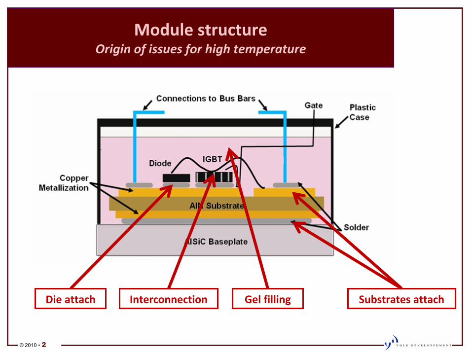
New�strategies�for�thermal�management� of�high�power�modules
APEC�2011
Fort�Worth,�TX
9�March�2011
Jeff�PerkinsBrice�Le�Gouic
© 2010 • 2
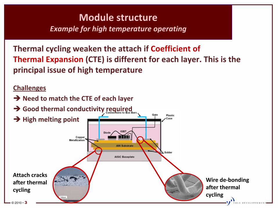
Module�structure Origin�of�issues�for�high�temperature
Die�attach Interconnection Gel�filling Substrates�attach
© 2010 • 3
Module�structure Example�for�high�temperature�operating
Thermal�cycling�weaken�the�attach�if�Coefficient�of�Thermal�Expansion�(CTE)�is�different�for�each�layer.�This�is�the�
principal�issue�of�high�temperature
ChallengesÎ Need�to�match�the�CTE�of�each�layerÎ Good�thermal�conductivity�requiredÎ High�melting�point
Attach�cracks�
after�thermal�
cycling
Wire�deͲbonding�
after�thermal�
cycling
© 2010 • 4
Die�attach Soldering,�the�historical�method
•
Soldering�is�a�fast,�cheap�and�easy�process–
They�use�a�paste�or�a�gel�for�soldering
–
Historically,�it�is�an�alloy�of�Tin�(Sn)�and�Lead�(Pb)�that�can�
handle�
–
But��Pb�is�to�be�abandoned�due�to�RoHS:
ÎPbͲfree�solution�is�Sn/Ag�(Tin/Silver)�soldering
ÎSoldering�is�not�suitable�for�high�temperature�or�multiple�steps
T°
max�is�220°C
© 2010 • 5
Die�attach TLPB,�melting�phases�at�liquid�state�
•
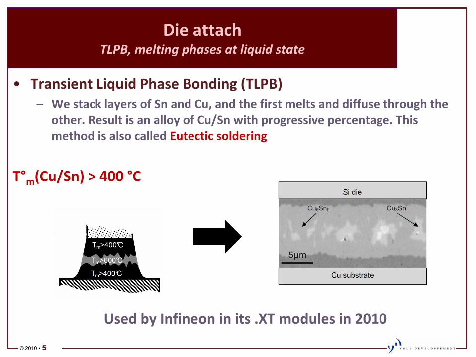
Transient�Liquid�Phase�Bonding�(TLPB)–
We�stack�layers�of�Sn�and�Cu,�and�the�first�melts�and�diffuse�through�the�
other.�Result�is�an�alloy�of�Cu/Sn�with�progressive�percentage.�This�
method�is�also�called�Eutectic�soldering�
T°m
(Cu/Sn)�>�400�°C
Used�by�Infineon�in�its�.XT�modules�in�2010
© 2010 • 6
•
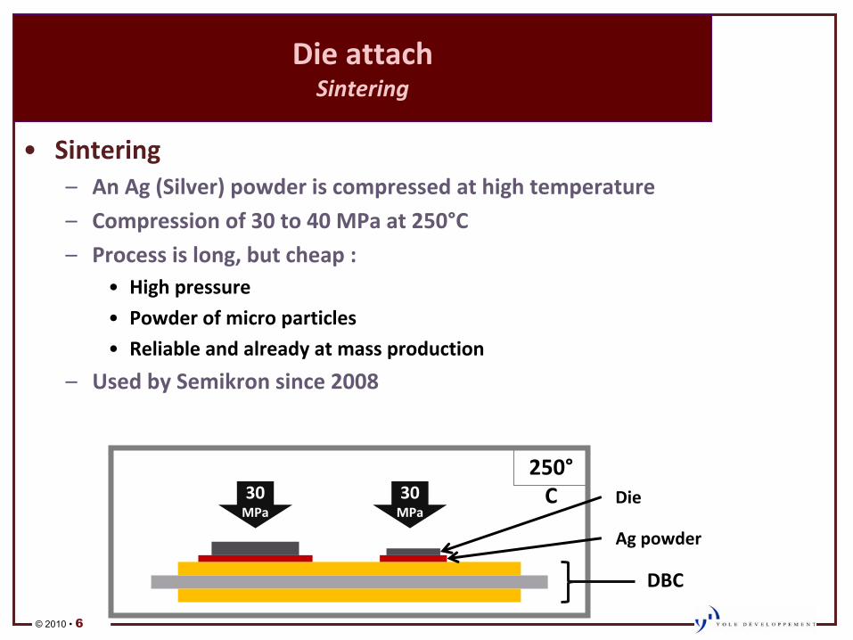
Sintering–
An�Ag�(Silver)�powder�is�compressed�at�high�temperature
–
Compression�of�30�to�40�MPa�at�250°C
–
Process�is�long,�but�cheap�:•
High�pressure
•
Powder�of�micro�particles
•
Reliable�and�already�at�mass�production
–
Used�by�Semikron�since�2008
Die�attach Sintering
30�
MPa
30�
MPa
250°
C Die
Ag�powder
DBC
© 2010 • 7
Die�attach Nanoparticle�sintering�is�under�investigation
•
Nanoparticle�sintering–
Same�principle�as�Ag�micro�particles�sintering
–
Using�nano�size�particles�allows�a�better�result�with�a�simpler�
process�:•
Temperature�is�much�lower�Î down�to�20°C
•
Pressure�and�time�are�also�reduced�Πfaster�thus�cheaper�process
–
This�technology�is�still�at�R&D�development•
Issues�from�the�migration�of�Ag�particles�at�high�temperature�still�
need�to�be�overcome
–
TimeͲtoͲmarket�:�2012
© 2010 • 8
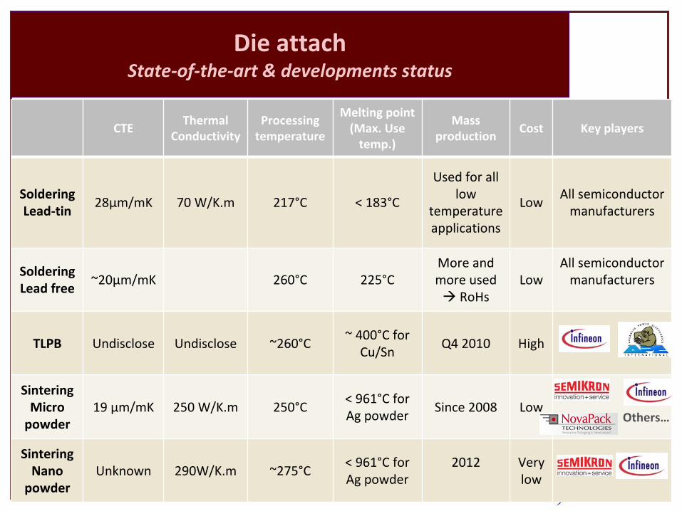
Die�attach StateͲofͲtheͲart�&�developments�status
CTEThermal�
Conductivity
Processing�
temperature
Melting�point(Max.�Use�
temp.)
Mass�
production
Cost Key�players
SolderingLeadͲtin
28µm/mK 70�W/K.m 217°C <�183°C
Used�for�all�
low�
temperature�
applications
LowAll�semiconductor�
manufacturers
SolderingLead�free
~20µm/mK 260°C 225°CMore�and�
more�used����Æ RoHs
LowAll�semiconductor�
manufacturers
TLPB Undisclose Undisclose ~260°C~�400°C�for�
Cu/Sn
Q4�2010 High
SinteringMicro�
powder
19�µm/mK 250�W/K.m 250°C<�961°C�for�
Ag�powder
Since�2008 Low
SinteringNano�
powder
Unknown 290W/K.m ~275°C<�961°C�for�
Ag�powder
2012 Very�
low
Others…
© 2010 • 9
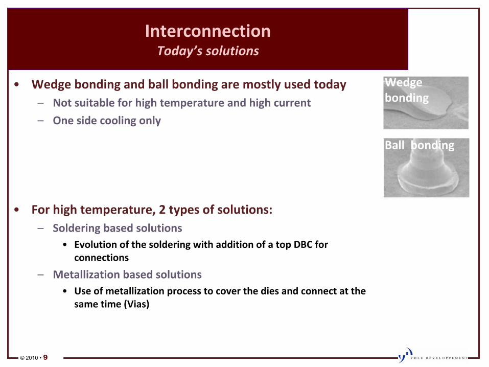
Interconnection Today’s�solutions
•
Wedge�bonding�and�ball�bonding�are�mostly�used�today–
Not�suitable�for�high�temperature�and�high�current
–
One�side�cooling�only
•
For�high�temperature,�2�types�of�solutions:–
Soldering�based�solutions•
Evolution�of�the�soldering�with�addition�of�a�top�DBC�for�
connections
–
Metallization�based�solutions•
Use�of�metallization�process�to�cover�the�dies�and�connect�at�the�
same�time�(Vias)
Wedge��
bonding
Ball��bonding
© 2010 • 10
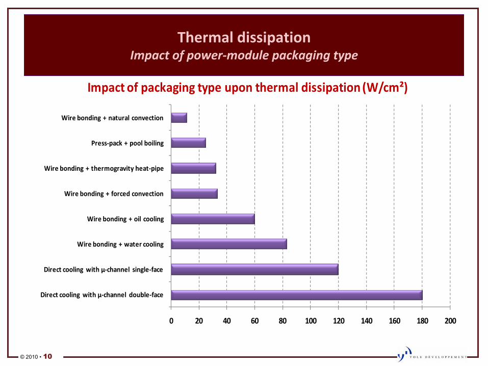
Thermal�dissipation
Impact�of�powerͲmodule�packaging�type�
0 20 40 60 80 100 120 140 160 180 200
Direct�cooling�with�µͲchannel�doubleͲface
Direct�cooling�with�µͲchannel� singleͲface
Wire�bonding�+�water�cooling
Wire�bonding�+�oil�cooling
Wire�bonding�+�forced�convection
Wire�bonding�+�thermogravity�heatͲpipe
PressͲpack�+�pool�boiling
Wire�bonding�+�natural�convection
Impact�of�packaging�type�upon�thermal�dissipation�(W/cm²)
© 2010 • 11
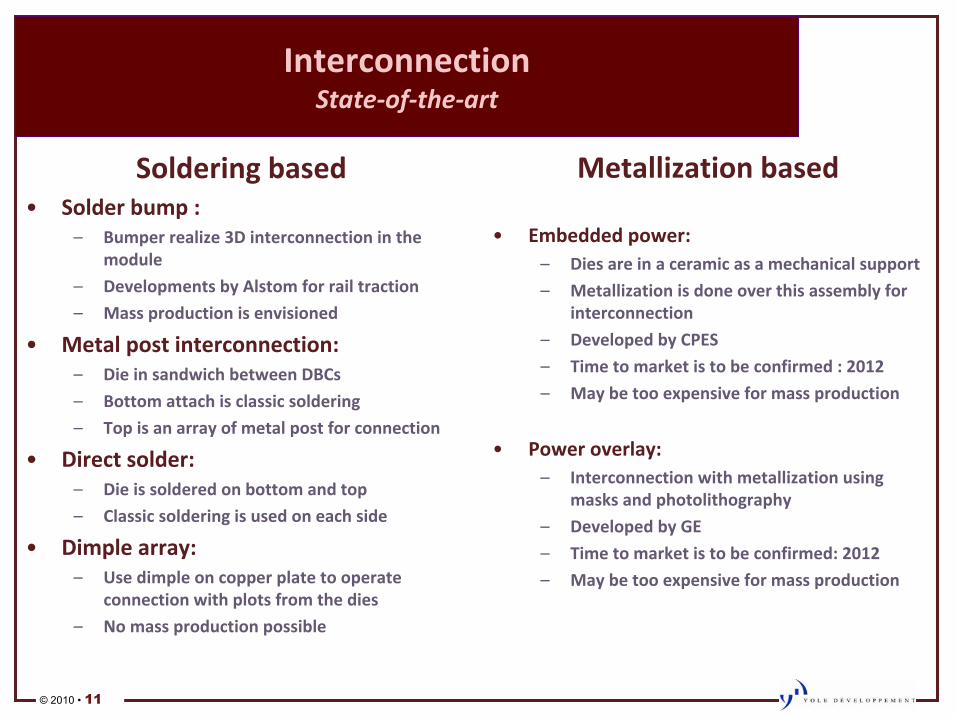
Interconnection StateͲofͲtheͲart
Soldering�based•
Solder�bump�:–
Bumper�realize�3D�interconnection�in�the�
module
–
Developments�by�Alstom�for�rail�traction
–
Mass�production�is�envisioned
•
Metal�post�interconnection:–
Die�in�sandwich�between�DBCs
–
Bottom�attach�is�classic�soldering
–
Top�is�an�array�of�metal�post�for�connection
•
Direct�solder:–
Die�is�soldered�on�bottom�and�top
–
Classic�soldering�is�used�on�each�side
•
Dimple�array:–
Use�dimple�on�copper�plate�to�operate�
connection�with�plots�from�the�dies
–
No�mass�production�possible
Metallization�based
•
Embedded�power:–
Dies�are�in�a�ceramic�as�a�mechanical�support
–
Metallization�is�done�over�this�assembly�for�
interconnection
–
Developed�by�CPES
–
Time�to�market�is�to�be�confirmed�:�2012
–
May�be�too�expensive�for�mass�production
•
Power�overlay:–
Interconnection�with�metallization�using�
masks�and�photolithography
–
Developed�by�GE
–
Time�to�market�is�to�be�confirmed:�2012
–
May�be�too�expensive�for�mass�production�
© 2010 • 12
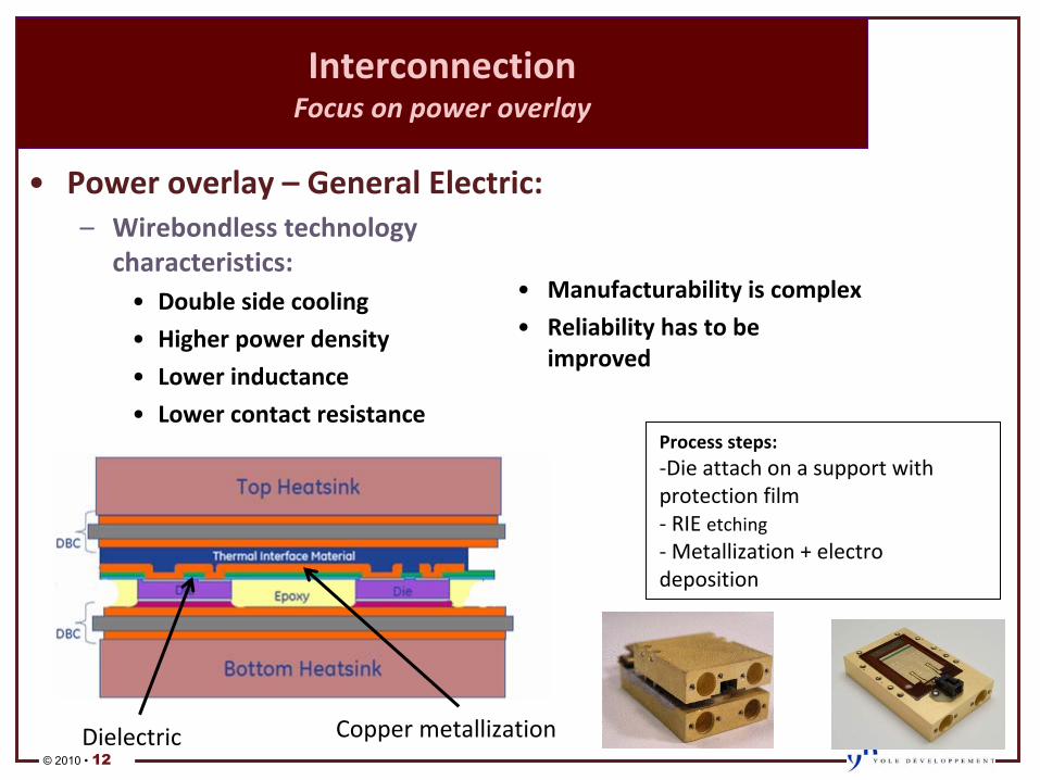
Interconnection Focus�on�power�overlay
•
Power�overlay�–
General�Electric:
–
Wirebondless�technology�
characteristics:•
Double�side�cooling
•
Higher�power�density�
•
Lower�inductance
•
Lower�contact�resistance
Copper�metallizationDielectric
Process�steps:ͲDie�attach�on�a�support�with�
protection�filmͲ RIE�etchingͲ
Metallization�+�electro�
deposition
•
Manufacturability�is�complex
•
Reliability�has�to�be�
improved
© 2010 • 13
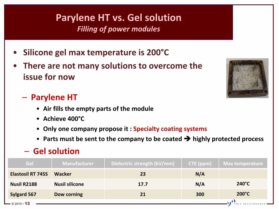
Parylene�HT�vs.�Gel�solution Filling�of�power�modules
–
Parylene�HT•
Air�fills�the�empty�parts�of�the�module
•
Achieve�400°C
•
Only�one�company�propose�it�:�Specialty�coating�systems
•
Parts�must�be�sent�to�the�company�to�be�coated�Πhighly�protected�process
Gel Manufacturer Dielectric�strength�(kV/mm) CTE�(ppm) Max�temperature
Elastosil�RT�745S Wacker 23 N/A
Nusil�R2188 Nusil�silicone 17.7 N/A 240°C
Sylgard�567 Dow�corning 21 300 200°C
–
Gel�solution
•
Silicone�gel�max�temperature�is�200°C
•
There�are�not�many�solutions�to�overcome�the�
issue�for�now
© 2010 • 14
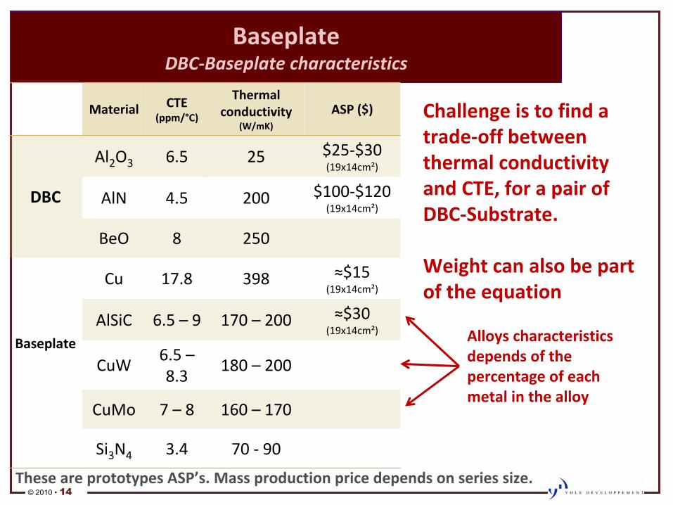
Baseplate� DBCͲBaseplate�characteristics
Material CTE(ppm/°C)
Thermal�
conductivity�
(W/mK)
ASP�($)
DBC
Al2
O3 6.5 25 $25Ͳ$30
(19x14cm²)
AlN 4.5 200 $100Ͳ$120
(19x14cm²)
BeO 8 250
Baseplate
Cu 17.8 398 у$15(19x14cm²)
AlSiC 6.5�– 9 170�– 200� у$30(19x14cm²)
CuW6.5�–
8.3
180�– 200�
CuMo 7�– 8 160�– 170�
Si3
N4 3.4 70�Ͳ
90
Alloys�characteristics�
depends�of�the�
percentage�of�each�
metal�in�the�alloy
Challenge�is�to�find�a�
tradeͲoff�between�
thermal�conductivity�
and�CTE,�for�a�pair�of�
DBCͲSubstrate.
Weight�can�also�be�part�
of�the�equation
These�are�prototypes�ASP’s.�Mass�production�price�depends�on�series�size.
© 2010 • 15
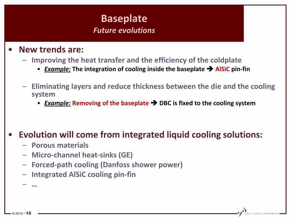
Baseplate� Future�evolutions
•
New�trends�are:–
Improving�the�heat�transfer�and�the�efficiency�of�the�coldplate•
Example:
The�integration�of�cooling�inside�the�baseplate�Î AlSiC�pinͲfin
–
Eliminating�layers�and�reduce�thickness�between�the�die�and�the�cooling�
system•
Example:
Removing�of�the�baseplate�ΠDBC�is�fixed�to�the�cooling�system
•
Evolution�will�come�from�integrated�liquid�cooling�solutions:–
Porous�materials–
MicroͲchannel�heatͲsinks�(GE)–
ForcedͲpath�cooling�(Danfoss�shower�power)–
Integrated�AlSiC�cooling�pinͲfin–
…
© 2010 • 16
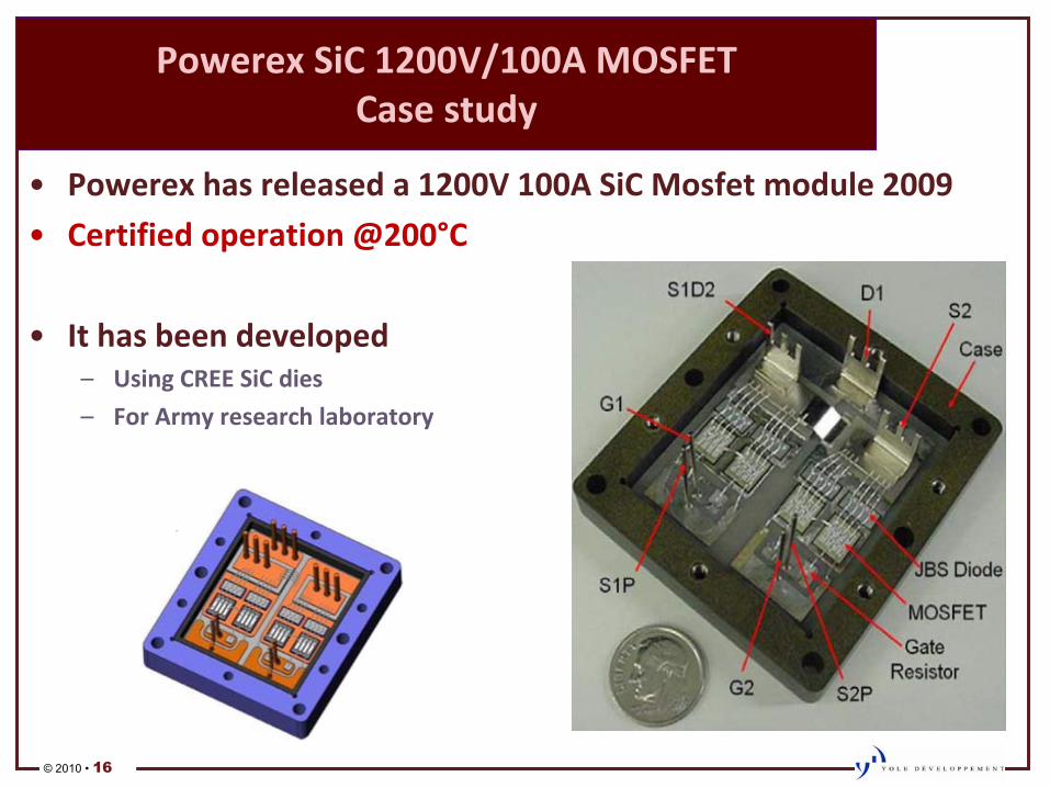
Powerex�SiC�1200V/100A�MOSFET Case�study
•
Powerex�has�released�a�1200V�100A�SiC�Mosfet�module�2009
•
Certified�operation�@200°C
•
It�has�been�developed–
Using�CREE�SiC�dies
–
For�Army�research�laboratory
© 2010 • 17
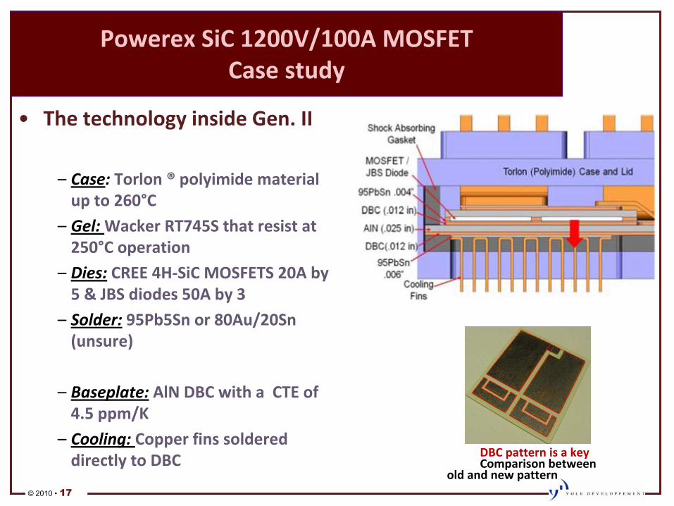
Powerex�SiC�1200V/100A�MOSFET Case�study
•
The�technology�inside�Gen.�II
–
Case:
Torlon�® polyimide�material�
up�to�260°C
–
Gel:�Wacker�RT745S�that�resist�at�
250°C�operation
–
Dies:
CREE�4HͲSiC�MOSFETS�20A�by�
5�&�JBS�diodes�50A�by�3
–
Solder:
95Pb5Sn�or�80Au/20Sn�
(unsure)
–
Baseplate:
AlN�DBC�with�a��CTE�of�
4.5�ppm/K
–
Cooling:�Copper�fins�soldered�
directly�to�DBC DBC�pattern�is�a�key
Comparison�between�
old�and�new�pattern
© 2010 • 18
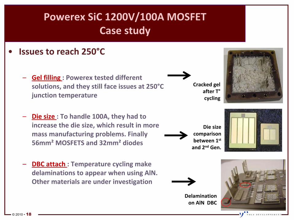
Powerex�SiC�1200V/100A�MOSFET Case�study
•
Issues�to�reach�250°C
–
Gel�filling�:�Powerex�tested�different�
solutions,�and�they�still�face�issues�at�250°C�
junction�temperature
–
Die�size�:�To�handle�100A,�they�had�to�
increase�the�die�size,�which�result�in�more�
mass�manufacturing�problems.�Finally�
56mm²
MOSFETS�and�32mm²
diodes
–
DBC�attach�:�Temperature�cycling�make�
delaminations�to�appear�when�using�AlN.�
Other�materials�are�under�investigation
Cracked�gel�
after�T°
cycling
Die�size�
comparison�
between�1st
and�2nd
Gen.
Delamination�
on�AlN��DBC
© 2010 • 19
THERMAL�MANAGEMENT� AT�SYSTEM�LEVEL
© 2010 • 20
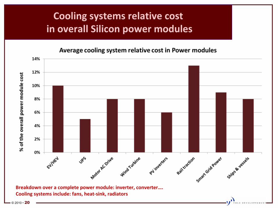
Cooling�systems�relative�cost in�overall�Silicon�power�modules
Breakdown�over�a�complete�power�module:�inverter,�converter….Cooling�systems�include:�fans,�heatͲsink,�radiators
© 2010 • 21
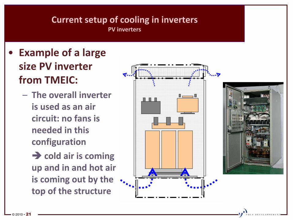
Current�setup�of�cooling�in�inverters
PV�inverters
•
Example�of�a�large� size�PV�inverter�
from�TMEIC:–
The�overall�inverter�
is�used�as�an�air�
circuit:�no�fans�is�
needed�in�this�
configuration
Î cold�air�is�coming�up�and�in�and�hot�air�is�coming�out�by�the�top�of�the�structure
© 2010 • 22
Impact�of�operation�T°
on�thermal�management
Motor�drives�in�industry�environment
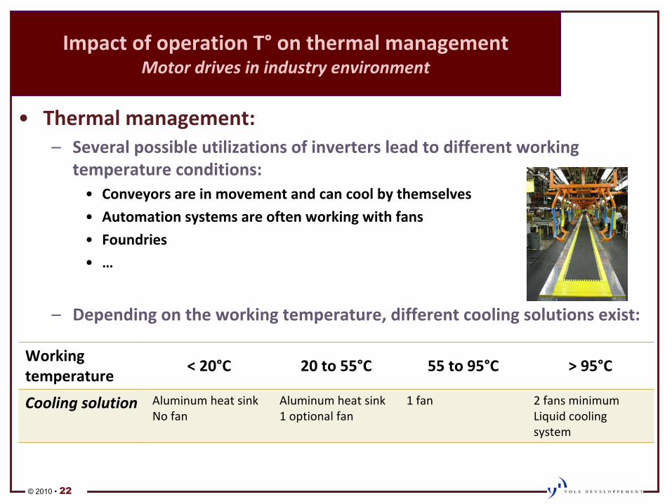
•
Thermal�management:–
Several�possible�utilizations�of�inverters�lead�to�different�working�
temperature�conditions:•
Conveyors�are�in�movement�and�can�cool�by�themselves
•
Automation�systems�are�often�working�with�fans
•
Foundries
•
…
–
Depending�on�the�working�temperature,�different�cooling�solutions�exist:
Working�
temperature
<�20°C 20�to�55°C 55�to�95°C >�95°C
Cooling�solution Aluminum�heat�sinkNo�fan
Aluminum�heat�sink1�optional�fan
1�fan 2�fans�minimumLiquid�cooling�
system
© 2010 • 23
Impact�of�operation�T°
on�thermal�management
Motor�drives�in�industry�environment
•
Configuration:
–
A�large�part�of�motor�drives�inverters�(especially�for�conveyors)�use�air�cooling:�under�55°C,�there�is�
almost�never�a�need�for�fans.
–
Depending�on�the�power�range,�a�fan�can�cost�from�2�to�50€,�it�roughly�represents�10%�of�the�inverter�
cost.
•
Therefore,�removing�fans�by�using�high�temperature�semiconductor
(SiC)�would�have�two�
positive�impacts:
–
Cost�Πreduction�of�10%�of�the�inverter�cost
–
Reliability�Πsuch�fans�have�to�be�replaced�every�50.000�hours,�which�implies frequent�stops�of�factories�
and�cost�of�maintenance
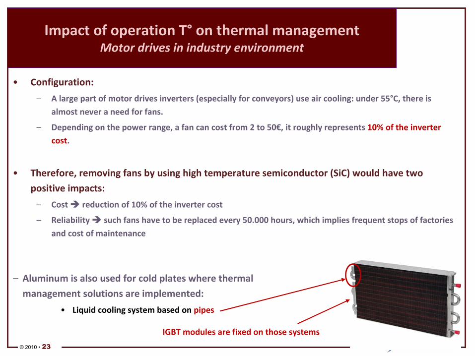
–
Aluminum�is�also�used�for�cold�plates�where�thermal�
management�solutions�are�implemented:
•
Liquid�cooling�system�based�on�pipes
IGBT�modules�are�fixed�on�those�systems
© 2010 • 24
SIC�FOR�HIGH�TEMPERATURE
© 2010 • 25
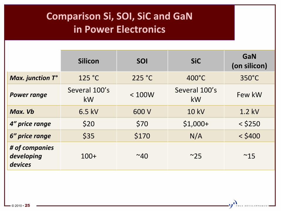
Comparison�Si,�SOI,�SiC�and�GaN� in�Power�Electronics
Silicon SOI SiCGaN
(on�silicon)
Max.�junction�T° 125�°C 225�°C 400°C 350°C
Power�rangeSeveral�100’s�
kW<�100W
Several�100’s�
kWFew�kW
Max.�Vb 6.5�kV 600�V 10�kV 1.2�kV
4”
price�range $20 $70 $1,000+ <�$250
6”
price�range $35 $170 N/A <�$400
#�of�companies�
developing�
devices
100+ ~40 ~25 ~15
© 2010 • 26
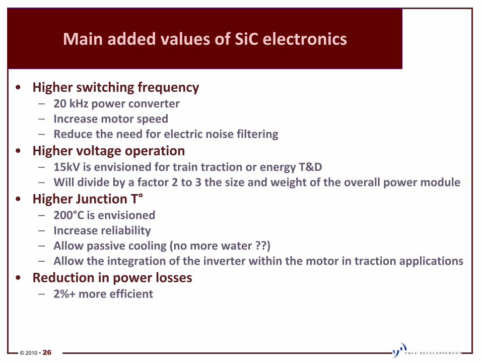
Main�added�values�of�SiC�electronics
•
Higher�switching�frequency–
20�kHz�power�converter–
Increase�motor�speed–
Reduce�the�need�for�electric�noise�filtering�•
Higher�voltage�operation–
15kV�is�envisioned�for�train�traction�or�energy�T&D–
Will�divide�by�a�factor�2�to�3�the�size�and�weight�of�the�overall�power�module•
Higher�Junction�T°–
200°C�is�envisioned–
Increase�reliability–
Allow�passive�cooling�(no�more�water�??)–
Allow�the�integration�of�the�inverter�within�the�motor�in�traction�applications•
Reduction�in�power�losses–
2%+�more�efficient
© 2010 • 27
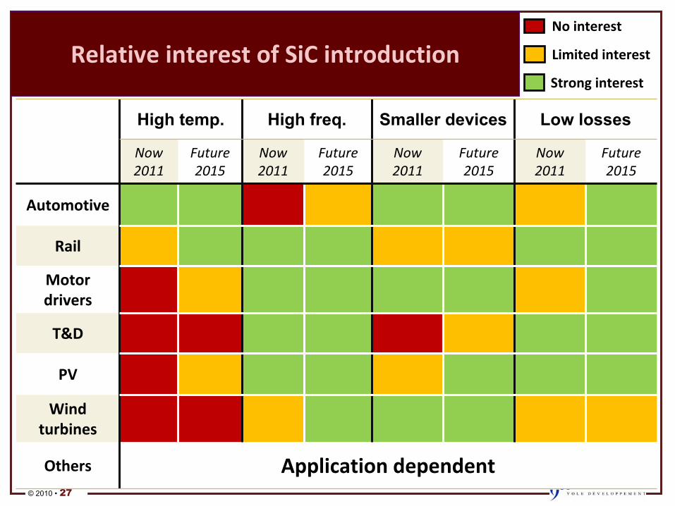
Relative�interest�of�SiC�introduction
High temp. High freq. Smaller devices Low losses
Now2011
Future2015
Now2011
Future2015
Now2011
Future2015
Now2011
Future2015
Automotive
Rail
Motor�
drivers
T&D
PV
Wind�
turbines
Others Application�dependent
No�interest
Limited�interest
Strong�interest
© 2010 • 28
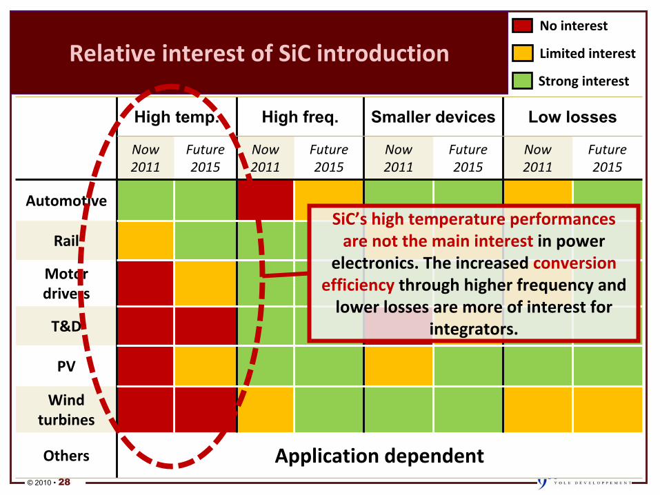
Relative�interest�of�SiC�introduction
High temp. High freq. Smaller devices Low losses
Now2011
Future2015
Now2011
Future2015
Now2011
Future2015
Now2011
Future2015
Automotive
Rail
Motor�
drivers
T&D
PV
Wind�
turbines
Others Application�dependent
No�interest
Limited�interest
Strong�interest
SiC’s�high�temperature�performances�
are�not�the�main�interest�in�power�
electronics.�The�increased�conversion�
efficiency
through�higher�frequency�and�
lower�losses�are�more�of�interest�for�
integrators.
© 2010 • 29
Your�contacts�at�YOLE
•
Your�contacts�at�YOLE�Développement:–
Brice�Le�Gouic,�Market�analyst�in�charge�of�
Power�Electronics�activities•
Email:�[email protected]•
Tel:�+33�472�83�01�81
–
Alexandre�Avron,�Market�analyst�in�Power�
Electronics•
Email:�[email protected]•
Tel:�+33�472�83�01�03
–
Jeffrey�Perkins,�General�Manager,�Yole�Inc.•
Email:�[email protected]•
Tel:�+1�650�906�7877
© 2010 • 30
Questions�&�Answers
Thank�you�for�your� attention
Questions�are�welcome
–
Jeffrey�Perkins,�General�Manager,�Yole
Inc.
•
Email:�[email protected]
•
Tel:�+1�650�906�7877
Contact�details:
Come�and��visit�us�at�our�booth
Come�and��visit�Come�and��visit�us�at�our�boothus�at�our�booth