Embed Size (px)
Citation preview

1
FORWARD COLLISION WARNING SYSTEM CONFIRMATION TEST
February 2013
Office of Vehicle Safety Office of Crash Avoidance Standards
National Highway Traffic Safety Administration Room W43-478, NVS-120
1200 New Jersey Avenue, SE Washington, DC 20590
2
FORWARD COLLISION WARNING SYSTEM CONFIRMATION TEST
TABLE OF CONTENTS
1.0 PURPOSE AND APPLICATION ........................................................................... 3
2.0 GENERAL REQUIREMENTS ............................................................................... 3
3.0 SECURITY ........................................................................................................... 3
4.0 GOOD HOUSEKEEPING ..................................................................................... 4
5.0 TEST SCHEDULING AND MONITORING ........................................................... 4
6.0 TEST DATA DISPOSITION .................................................................................. 5
7.0 VEHICLES AND EQUIPMENT (GFP) .................................................................. 7
8.0 INSTRUMENTATION AND CALIBRATION.…………………………………………6 9.0 PHOTOGRAPHIC DOCUMENTATION ............................................................. 11
10.0 DEFINITIONS ..................................................................................................... 13
11.0 PRETEST AND FACILITY REQUIREMENTS .................................................... 14
12.0 TEST EXECUTION AND TEST REQUIREMENTS ............................................ 19
13.0 POST TEST REQUIREMENTS .......................................................................... 25
14.0 REPORTS .......................................................................................................... 25
15.0 DATA SHEETS ................................................................................................... 33
16.0 REFERENCES ................................................................................................... 37
17.0 EQUATIONS FOR CALCULATING TTC VALUES ............................................. 38
3
1.0 PURPOSE AND APPLICATION This laboratory test procedure provides specifications for conducting tests to confirm the existence of a Forward Collision Warning (FCW) system on a passenger vehicle with a gross vehicle weight rating (GVWR) of under 10,000 pounds. Current FCW technology is dependent on radar-based and/or vision based sensors capable of detecting traffic. Although it is impossible to predict what technologies could be used in future FCW systems, it is believed that with minor modifications to the test setup, other technologies may be evaluated. The requirements of this indicant test procedure must be strictly adhered to. The Contractor's in-house test procedure must have NHTSA approval prior to conducting the first test of a particular fiscal year program. The Contractor's test procedure cannot deviate in any way from the NHTSA procedure without the prior approval of the NHTSA COTR. 2.0 GENERAL REQUIREMENTS This test evaluates the ability of a forward collision warning system to detect and alert drivers of potential hazards in the path of the vehicle. Three driving scenarios are utilized to assess this technology. In the first test, a subject vehicle (SV) approaches a stopped principle other vehicle (POV) in the same lane of travel. The second test begins with the SV initially following the POV at the same constant speed. After a short while, the POV stops suddenly. The third test consists of the SV, traveling at a constant speed, approaching a slower moving POV, which is also being driven at a constant speed. 3.0 SECURITY The Contractor shall provide appropriate security measures to protect test vehicles and equipment during the entire test program, and shall be responsible for all equipment removed from test vehicles before and after the test. Vehicle equipment thefts or act of vandalism must be reported to NHTSA authorities immediately. Under no circumstances shall any vehicle components be removed during a visitor inspection unless authorized by OCAS engineers. All data developed from the test program shall be protected. Rules for Contractors
A. No vehicle manufacturer's representative(s), or anyone other than the Contractor's personnel working on the Contracts and NHTSA personnel, shall be allowed to inspect NHTSA vehicles or witness vehicle preparations and/or testing without prior permission of the Office of Crash Avoidance Standards (OCAS). Such permission can never be assumed.
B. All communications with vehicle manufacturers shall be referred to the OCAS,
4
and at no time shall the Contractor release test data without the permission of the OCAS
C. Unless otherwise specified, the vehicle manufacturer's representatives shall only
be authorized to visit the Contractor's test facility on the day that the test is scheduled, and the representatives must be escorted by NHTSA and/or Contractor personnel.
D. Test vehicle inspection by the vehicle manufacturer's representative(s) shall be
limited to 30 minutes prior to the start of vehicle test. Post-test inspection shall be limited to 1 hour after Contractor personnel have completed their test tasks.
E. Photographs and videos of the test vehicle, associated test equipment and test
event shall be allowed. However, test personnel shall not be included in any photographic coverage, and videotaping of vehicle preparation must be approved by OCAS. The Contractor's personnel shall not respond to any questions from the manufacturer's representatives regarding this test program. All questions shall be referred to the COTR, an OCAS representative present at the test site, or to OCAS.
F. The Contractor shall permit public access to and inspection of the test vehicles
and related data during the times specified by the NHTSA COTR. NHTSA shall advise interested parties that such access and inspection shall be limited to a specified day, specified hours, and require prior approval from the OCAS. The Contractor shall refer all visit requests from vehicle manufacturer's representatives and consumers to the OCAS. This service shall be included as an incidental part of the test program and will not result in any additional cost to the NHTSA. The Contractor shall make his own arrangements with interested parties for expenses incurred beyond providing access and inspection services. All inquiries by manufacturers concerning the test program (vehicle, procedures, data, etc.) shall be directed to OCAS representatives.
4.0 GOOD HOUSEKEEPING The Contractor will maintain the entire test area, vehicle pre-test preparation facility, instrumentation building, and equipment configuration and performance verification test laboratory in a clean, organized and painted condition. All test instrumentation must be setup in an orderly manner consistent with good engineering practices. 5.0 TEST SCHEDULING AND MONITORING The Contractor shall commence testing within four (4) weeks after receipt of the first test vehicle. Subsequent tests will be conducted, if requested, at a minimum of one (1) vehicle test per week. The NHTSA COTR will make adjustments to the test schedule in cases of unusual circumstances such as inclement weather or difficulty experienced by in the procurement of a particular vehicle make and model. All testing shall be
5
coordinated to allow monitoring by the COTR.
6.0 TEST DATA DISPOSITION The Contractor shall make all test data available within two hours after the test event if so requested by Agency personnel. Under no circumstances shall this preliminary data be furnished to non-Agency personnel. The Contractor shall analyze the preliminary test results as directed by the COTR. 6.1 Computer Data Tape and Final Hard-Copy
The Contractor shall deliver to OCAS the final data, digital printouts, and plots within one (1) week after the test.
6.2 Test Report 6.2.1 This test report shall include all of the items shown in the Sample Test Report.
The Contractor shall submit two (2) CD’s and one (1) paper copy of the test report to the following address:
U. S. Department of Transportation National Highway Traffic Safety Administration Office of Crash Avoidance Standards (NVS-120) 1200 New Jersey Avenue, SE, Room W43-478 Washington, DC 20590
6.2.2 Report Submission
All final test reports shall be submitted to the above listed NHTSA office within four (4) weeks from the date of the vehicle test.
6.2.3 Text/Data Sheet CD/DVD
The Contractor shall submit one (1) CD or DVD of the text and data sheet portion only of the test report in Microsoft Word format within four (4) weeks from the date of the vehicle test. The full test report including photographs and data traces on a CD or DVD may be a future requirement.
6.3 Test Video
OCAS shall receive one (1) copy of the color video for each test, and the copies shall be mailed directly to the OCAS within four (4) weeks of the vehicle test. The master print for each of the test videos shall be retained by the Contractor, but will be made available to the OCAS upon request. See Section 9.1 for a description of the video to be taken during FCW test conduct.
6
6.4 Data Loss 6.4.1 Conditions for Retest
The test vehicle is instrumented in order to obtain data needed for the test program. An invalid test is one which does not conform precisely to all requirements/specifications of the laboratory test procedure and Statement of Work applicable to the test.
The contracting officer of NHTSA is the only NHTSA official authorized to notify the Contractor that a retest is required.
No test report is required for any test which is determined to be invalid unless NHTSA specifically decides to require the Contractor to submit such report. Invalidated test reports will not be publicly released.
______________________________________________________________________
RETEST CONDITIONS
Failure of the Contractor to obtain the specified data and to maintain acceptable limits of test parameters in the manner outlined in this test procedure shall require a retest at the expense of the Contractor. The provisions of this paragraph apply to, but are not limited to, the Contractor maintaining proper speed tolerance, vehicle performance, and test data acquisition, reduction, and processing. The Contractor shall also be responsible for obtaining usable data from all primary channels from instrumentation placed in each vehicle. Failure to produce such data shall also be at the expense of the Contractor and shall include vehicle repair or replacement and retest unless the Office of Crash Avoidance Standards determines that the data loss occurred through conditions beyond reasonable and foreseeable control of the Contractor. Should it become necessary for the Contractor to procure another test vehicle, it must have identical equipment and options as the original vehicle. The retested vehicle shall be retained without fee by the testing facility until its disposal is authorized by the COTR. ______________________________________________________________________ 6.4.2 Conditions for Partial Payment
The Contractor shall exercise reasonable and foreseeable control to insure that no data is lost or rendered useless. If some non-critical data (such as camera failure) and critical data (such as vehicle position data) are not obtained for the test and the test is accepted by the Agency, the Agency will not pay for the missing or lost data.
7
6.5 Data Retention by Contractor
The Contractor shall retain at no extra cost to the agency, reproducible copies of all data (analog and digital), videos, and still photograph negatives or electronic files.
6.6 Data Availability to the Public
The Contractor shall provide interested parties with copies of test report, test CD’s, test data tapes, test films, and test still photographs, at a reasonable cost to the purchaser, but only after the OCAS representative has advised the Contractor that the results of that particular test have been released to the public by the Agency.
6.7 Indicant Failure Notification
Any indication of a “test failure” shall be communicated by telephone to COTR within 24 hours of the test.
NOTE: In the event of a failure, a post-test calibration check of some critically sensitive test equipment and instrumentation may be required for verification of accuracy. The necessity for the calibration shall be at the COTR's discretion and shall be performed without additional cost.
7.0 VEHICLES AND EQUIPMENT (GFP) 7.1 Acceptance of Test Vehicles
The Contractor has the responsibility of accepting leased or NHTSA-provided test vehicles from new car dealers, leasing companies, or vehicle transporters. In all instances, the Contractor acts in the NHTSA’s behalf when signing an acceptance of test vehicles. The Contractor must check to verify the following:
A. All options listed on the “window sticker” are present on the test vehicle.
B. Tires and wheel rims are the same as listed.
C. There are no dents or other interior or exterior flaws.
D. The vehicle has been properly prepared and is in running condition.
E. Verify that spare tire, jack, lug wrench, and tool kit (if applicable) is located in
the vehicle cargo area.
The Contractor shall check for damage that may have occurred during transit or prior use. The COTR is to be notified of any damage prior to preparation of the vehicle for testing.
8
7.2 Notification of COTR The COTR must be notified within 24 hours after a vehicle has been delivered. 7.3 Government Furnished Equipment (GFE)
For the FCW tests, no Government Furnished Equipment will be available or provided.
8.0 INSTRUMENTATION AND CALIBRATION 8.1 Test Equipment
A. Portable tire pressure gage with an operating pressure of at least 700kPa (100 psi), graduated increments of 1.0 kPa (0.1 psi) and an accuracy of at least + 2.0% of the applied pressure.
B. Global Positioning System (GPS), comprised of a base station and rover, with
post-processing software. Hardware and software solution shall provide position data (latitude and longitude) with at least 0.4 in (1.0 cm) static accuracy (Novatel ProPak-V3 and Waypoint GrafNav or equivalent), and update at a rate of at least 10 Hz.
C. Data acquisition system to record the FCW alert status (on or off), time, GPS
data, and a yaw rate sensor. GPS data shall be collected with a sample rate of at least 20 Hz. Since the CAN broadcast rate is a vehicle-dependent (e.g., subject to update rate, bus traffic, prioritization, etc.), specifying a sample rate to collect CAN data is not possible. Rather, CAN data shall be sampled as it is transmitted by the vehicle.
D. Signal conditioning shall consist of amplification, anti-alias filtering (optional
on alert channels), and digitizing. Amplifier gains are to be selected to maximize the signal-to-noise ratio of the digitized data. A power spectrum density (PSD) analysis of analog alert channels should be performed prior to data capture in order to determine the dominant frequency for these channels.
Filter Design
i. Digital data obtained from a GPS/Inertial Measurement Units (IMU) that has already had anti-alias filtering applied does not need any further filtering assuming the data is in real time (updates of 10 milliseconds and a latency of 3.5 milliseconds)
ii. Anti-alias filtering should be performed on analog data obtained from a GPS/IMU and designed using the following minimum specifications:
9
a. The minimum sampling rate should be 400 Hz and a multiple of 200 Hz
i. If the channel is an alert channel, then the minimum sampling rate of alert channels should be four (4) times the frequency determined in the PSD
b. Passband should be set between zero (0) and five (5) Hz c. Signal error as a result from passband ripples should be less
than 1%. d. Stopband frequencies should be attenuated to less than 1%.
iii. Anti-alias filtering does not need to be performed on alert channels. If anti-aliasing is performed on alert channels, follow the minimum specifications listed above. The absolute value of alert channels is not the desired variable; instead the time of onset (the TTC) is of interest.
a. If anti-alias filtering is not performed: i. The minimum sampling rate of alert channels should
be four (4) times the frequency determined in the PSD ii. Data shall be filtered using a phase-less, narrowband
filter to distinguish the actual signal from background noise
1. Passband frequency should be set to minimize the delay of the signal to reach maximum value in 0.1 seconds, but should be narrow enough to eliminate noise of non-alert frequencies.
iv. All digital and analog data should then be down sampled to 100 Hz (this will synchronize all of the data channels). The data should then be filtered to eliminate mid-range frequencies that were not eradicated by anti-alias filtering. The filter should have the following specifications:
a. A 6th order Butterworth filter performed in both forward and reverse directions
b. 5 Hz passband frequency (can be achieved by selecting a 10 Hz corner frequency)
8.2 Calibration
Before the Contractor initiates the test program, a test instrumentation calibration system must be implemented and maintained in accordance with established calibration practices. Guidelines for setting up and maintaining such calibration systems are described in MIL-C-45662A, “Calibration System Requirements.” The calibration system shall be set up and maintained as follows:
10
A. Standards for calibrating the measuring and test equipment will be stored and used under appropriate environmental conditions to assure their accuracy and stability.
B. All measuring instruments and standards shall be calibrated by the
Contractor, or a commercial facility, against a higher order standard at periodic intervals not exceeding twelve (12) months. Records, showing the calibration traceability to the National Institute of Standards and Technology (NIST), shall be maintained for all measuring and test equipment. The calibration frequency can be increased if deemed necessary by NHTSA.
C. All measuring and test equipment and measuring standards will be labeled
with the following information:
1. Date of calibration 2. Date of next scheduled calibration 3. Name of the organization and the technician who calibrated the
equipment D. A written calibration procedure shall be provided by the Contractor which
includes as a minimum the following information for all measurement and test equipment:
1. Type of equipment, manufacturer model number, etc. 2. Measurement range 3. Accuracy 4. Calibration interval 5. Type of standard used to calibrate the equipment (calibration
traceability of the standard must be evident) 6. The actual procedures and forms used to perform the calibrations.
E. Records of calibration for all test instrumentation shall be kept by the Contractor in a manner that assures the maintenance of established calibration schedules. All such records shall be readily available for inspection when requested by the COTR and shall be included in the final test report. The calibration system will need the acceptance of the COTR before testing commences.
F. Test equipment shall receive a pre- and post-test zero and calibration check.
This check shall be recorded by the test technician(s) and submitted with the final report.
NOTE: In the event of a failure to meet the standard's minimum performance
11
requirements additional calibration checks of some critically sensitive test equipment and instrumentation may be required for verification of accuracy. The necessity for the calibration will be at the COTR's discretion and will be performed without additional cost the OCAS.
8.3 Test Vehicle Measurement and Preparation
A. The Contractor shall supply a mid-sized passenger vehicle for use as a target principle other vehicle. Alternatively, and with OCAS approval, the Contractor may use other target equipment provided it has the physical characteristics and radar profile representative of a mid-sized passenger vehicle. If the use of alternative target equipment is proposed, the Contractor shall present documentation that objectively quantifies how the alternative target equipment represents an actual mid-sized passenger vehicle.
B. The SV and POV vehicle tires shall be inflated to the recommended cold
inflation pressure as specified on the vehicle placard or optional tire inflation pressure label.
C. All non-consumable fluids must be at 100 percent capacity. Fuel must be
maintained at least 75 percent capacity during the testing.
D. The SV and POV shall be loaded with one driver and all required equipment during the testing. Where possible, the equipment shall be placed on the passenger side of the vehicle. . The vehicle weight should be measured and recorded with the driver and all required equipment included.
E. The centerline of the SV and POV shall be determined. For each vehicle, the
lateral, longitudinal, and vertical position of the GPS antenna shall be measured and recorded.
F. In the case of the SV, the longitudinal distance from the GPS antenna to the
front-most position of the front bumper shall be measured and recorded. Similarly, the longitudinal distance from the GPS antenna to the rear-most position of the rear bumper shall be measured and recorded for the POV. Use of a highly accurate measurement arm with a tolerance of ±0.10 in (±0.25 cm) is recommended for making the vehicle dimension measurements. SAE vehicle dimension measurement methodology should be used.
9.0 PHOTOGRAPHIC DOCUMENTATION Each vehicle shall be documented on color still pictures. Each test shall be documented on a color video camera. Light glare and shadows must be minimized so that views of the test are visible for visual analysis.
12
9.1 Cameras Required
CAMERA 1: Real-time video inside of the SV.
CAMERA 2: Real-time video camera to one side of the most significant even area of the test. CAMERA 3: A still camera to document the vehicle.
9.2 Informational Placards
Vehicle identification placards shall be positioned so that at least one placard will be visible in the field-of-view for at least one video camera. The following information will be shown:
A. Vehicle's NHTSA Number B. The words “OCAS FORWARD COLLISION WARNING CONFIRMATION
TEST” C. Date of test D. Name of contract laboratory E. Vehicle year, make and model
9.3 Test Film Title and Ending
Test video shall include the following title frames:
A. “The following Forward Collision Warning test was conducted under contract with the National Highway Traffic Safety Administration by (name and location of test laboratory)”
B. OCAS FORWARD COLLISION WARNING CONFIRMATION TEST TEST VEHICLE MODEL YEAR, MAKE AND MODEL NHTSA No. CXXXXX DATE OF EVENT CONTRACT NO.: DTNH22-XX-X-XXXXX C. The ending frame shall state “THE END”
13
9.4 Film Editing
The film shall be edited in the following sequence:
A. Title
B. Pretest Coverage
C. Real Time Pan Coverage
D. Post-test Coverage
E. “The End” Any vehicle failures shall be completely documented.
9.5 Still Photographs
The following still photographs (8 x 10 inch or 81/2 x 11 inch color prints properly focused for clear images) are required for the test:
A. Pretest, non-instrumented pictures of the SV and POV vehicles (front, rear,
and four three-quarter pictures) B. Pretest, instrumented pictures of the SV and POV vehicles (front, rear, four
three-quarter pictures, and pictures of the instrumentation) C. SV and POV vehicle and tire placards
10.0 DEFINITIONS
Forward Collision Warning (FCW) systems are intended to passively assist the driver in avoiding or mitigating the impact of rear-end collisions (i.e., a vehicle striking the rear portion of a vehicle traveling in the same direction directly in front of it). These types of safety systems have forward-looking vehicle detection capability, such as RADAR, LIDAR (laser), camera, etc., and use the information from these sensors to warn the driver and thus to prevent crashes. 10.1 System Purpose:
FCW systems provide an audible, visual, or haptic warning, or any combination thereof, to alert the driver of an FCW-equipped vehicle of a potential collision with another vehicle or vehicles in the anticipated forward pathway of the vehicle. FCW may be provided in combination with adaptive cruise control (ACC); however use of any form of ACC automatic vehicle control is not permitted during the following tests. Non-adaptive cruise control shall not be permitted during the following tests. The driver shall modulate the throttle.
14
10.2 System Attributes:
A. Provides for continuous monitoring of vehicles in the forward pathway of the FCW-equipped vehicle using sensing/communications technologies such as RADAR, LIDAR (laser), camera, etc., or any combination thereof. The FCW could function such that it is inactive in situations where the vehicle is traveling below a preset speed threshold and/or when the driver has turned the system off.
B. The FCW tests do not require that the POV with which the equipped vehicle
may potentially collide with be equipped with any special equipment, however the POV shall be equipped with a rear license plate to maximize the ability of the SV to detect the POV.
C. If the sensing device has detected a vehicle in the forward pathway of a
FCW-equipped vehicle and there is a significant risk of a collision, an audible, visual, or haptic warning, or any combination thereof, must be presented to the driver of the FCW-equipped vehicle to help the driver avoid or mitigate a potential collision.
D. There may be weather and/or infrastructure situations when the FCW system
cannot detect vehicles in the forward pathway. FCW systems may also be limited in capability and/or accuracy due to other factors such as sensor blockage or interference, visibility conditions, roadway geometry, etc. It is not the intention of the tests procedure described in this document to simulate or accommodate these situations, as false, delayed, or missed warnings may occur.
11.0 PRETEST AND FACILITY REQUIREMENTS 11.1 Detailed Test and Quality Control Procedures Required
Prior to conducting any test, Contractors are required to submit a detailed in-house test procedure to the COTR which includes: A. A step-by-step description of the methodology to be used that follows the
necessary protocols outlined in this document. B. A written Quality Control (QC) Procedure which shall include calibrations, the
data review process, report review, and the people assigned to perform QC on each task.
C. A complete listing of test equipment which shall include instrument accuracy
and calibration dates. D. Detailed check off lists to be used during the test and during data review.
15
These lists shall include all test procedure requirements. Each separate check off sheet shall identify the lab, test date, vehicle and test technicians. These check sheets shall be used to document that all requirements and procedures have been complied with for each test. The check sheets should be kept on file.
There shall be no contradiction between the laboratory test procedure and the Contractor's in-house test procedure. The procedures shall cover all aspects of testing from vehicle receipt to submission of the final report. Written approval of the procedures must be obtained from the COTR before initiating the test program so that all parties are in agreement.
11.2 Road Test Surface
Unless specified otherwise, the road surface where the test is to be carried out shall be dry (without visible moisture on the surface). The roadway shall be straight and flat, with pavement in good condition. The roadway surface shall be constructed from asphalt or concrete, and free of potholes, bumps, and cracks that could cause the SV to pitch excessively. Each trial shall be conducted with no vehicles, obstructions, or stationary objects within one lane width of either side the vehicle path. The roadway used for the FCW tests may be delineated with up to two solid white lane lines. If a single lane line is used, the centerline of the SV and POV shall be 6.0 ft (1.8 m) from the inside edge of the line for the duration of the test. Additionally, the orientation of the SV and POV centerlines to the single lane line shall remain constant for the duration of the test. Example: If the single line is 6.0 ft (1.8 m)from left side of the SV centerline at the beginning of the test, the line shall also be 6.0 ft (1.8 m)the left side of the POV centerline. If two lane lines are present, the distance between the inside edges shall be at least 12 feet (3.7 m), and the vehicles shall remain in the center of the lane for the duration of the trial.
11.2.1 Pavement Friction
All maneuvers are to be performed on a dry, high-friction road test surface with a peak friction coefficient (PFC) of 0.9 when measured using an ASTM E1136 standard reference test tire, in accordance with ASTM Method E 1337–90, at a speed of 40 mph (64.4 km/h), without water delivery.
11.3 Ambient Conditions 11.3.1 Ambient Temperature The ambient temperature shall be between 32° F (0° C) and 100° F (38° C).
16
11.3.2 Wind Speed The maximum wind speed shall be no greater than 22 mph (35 km/h). 11.3.3 Inclement Weather
Tests should not be performed during periods of inclement weather. This includes, but is not limited to, rain, snow, hail, fog, smoke, or ash.
11.3.4 Visibility
Unless specified otherwise, the tests shall be conducted during daylight hours with good atmospheric visibility defined as an absence of fog and the ability to see clearly for more than 3 mi (5000 m). Tests shall not be conducted with the vehicle oriented into the sun during very low sun angle conditions, where the sun is oriented 15 degrees or less from horizontal and potential camera “washout” or system inoperability could result.
Unless stated otherwise, all tests shall be conducted such that there are no overhead signs, bridges, or other significant structures over, or near, the testing site. Each trial shall be conducted with no vehicles, obstructions, or stationary objects within one lane width of either side the vehicle path.
11.4 Calibration Data
It is strongly recommended that calibration data be collected prior to tests of each configuration to assist in resolving uncertain test data.
A. The distance measured by the speed sensor along a straight line between the
end points of a surveyed linear roadway standard of 1000 ft (300 m) or more, observed and recorded manually from the speed sensor display.
B. Five to fifteen seconds of data from all instrument channels as the test vehicle
is driven in a straight line on a level, uniform, solid-paved road surface at 60 mph (97 km/h).
11.5 Instrumentation Required
Each test vehicle is to be equipped with instrumentation and a data acquisition system. Equipment location and weight specifications are presented in Table 1.
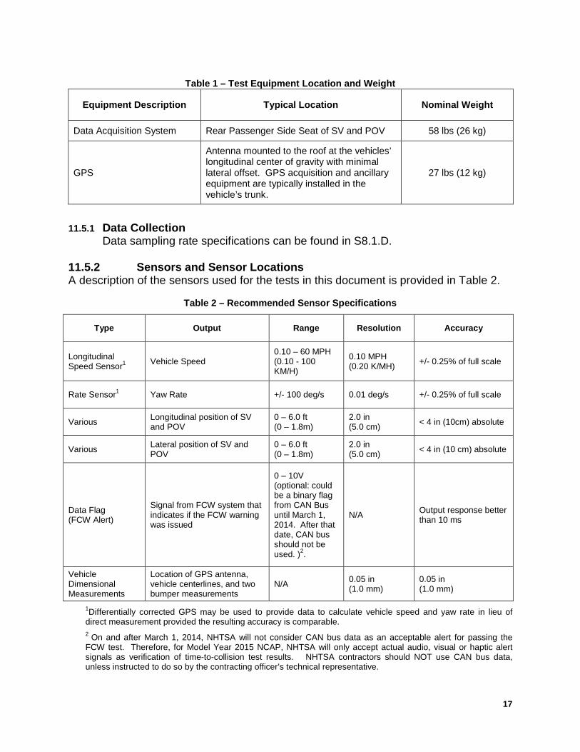
17
Table 1 – Test Equipment Location and Weight
Equipment Description Typical Location Nominal Weight
Data Acquisition System Rear Passenger Side Seat of SV and POV 58 lbs (26 kg)
GPS
Antenna mounted to the roof at the vehicles’ longitudinal center of gravity with minimal lateral offset. GPS acquisition and ancillary equipment are typically installed in the vehicle’s trunk.
27 lbs (12 kg)
11.5.1 Data Collection
Data sampling rate specifications can be found in S8.1.D. 11.5.2 Sensors and Sensor Locations A description of the sensors used for the tests in this document is provided in Table 2.
Table 2 – Recommended Sensor Specifications
Type Output Range Resolution Accuracy
Longitudinal Speed Sensor1 Vehicle Speed
0.10 – 60 MPH (0.10 - 100 KM/H)
0.10 MPH (0.20 K/MH) +/- 0.25% of full scale
Rate Sensor1 Yaw Rate +/- 100 deg/s 0.01 deg/s +/- 0.25% of full scale
Various Longitudinal position of SV and POV
0 – 6.0 ft (0 – 1.8m)
2.0 in (5.0 cm) < 4 in (10cm) absolute
Various Lateral position of SV and POV
0 – 6.0 ft (0 – 1.8m)
2.0 in (5.0 cm) < 4 in (10 cm) absolute
Data Flag (FCW Alert)
Signal from FCW system that indicates if the FCW warning was issued
0 – 10V (optional: could be a binary flag from CAN Bus until March 1, 2014. After that date, CAN bus should not be used. )2.
N/A Output response better than 10 ms
Vehicle Dimensional Measurements
Location of GPS antenna, vehicle centerlines, and two bumper measurements
N/A 0.05 in (1.0 mm)
0.05 in (1.0 mm)
1Differentially corrected GPS may be used to provide data to calculate vehicle speed and yaw rate in lieu of direct measurement provided the resulting accuracy is comparable. 2 On and after March 1, 2014, NHTSA will not consider CAN bus data as an acceptable alert for passing the FCW test. Therefore, for Model Year 2015 NCAP, NHTSA will only accept actual audio, visual or haptic alert signals as verification of time-to-collision test results. NHTSA contractors should NOT use CAN bus data, unless instructed to do so by the contracting officer’s technical representative.
18
The microphone should be placed in close proximity to the source of the sound. A unidirectional accelerometer may be used to capture tactile alerts in the steering wheel and/or driver’s seat. A Light sensor should be able to capture changes in LDW icon alert if possible and rapid onset of a LDW icon. Location of the light sensor is vehicle dependent. All visual, audible, and haptic sensors should meet the range, resolution, and accuracy specifications stated above the FCW data flag. 11.5.2.1 Vehicle Speed
Vehicle speed shall be measured. Use of contact or non-contact based speed sensors is acceptable. Alternatively, GPS based sensors that have an update rate ≥ 100 Hz are acceptable. Sensor outputs are to be transmitted not only to the data acquisition system, but also to a dashboard display unit. This allows the driver to accurately monitor vehicle speed.
11.5.2.2 Yaw Rate
Yaw rate shall be measured. Corrected GPS may be used to provide data to calculate yaw rate in lieu of direct measurement, provided the resulting accuracy is comparable.
11.5.2.3 Longitudinal and Lateral Position
Longitudinal and lateral position of the SV and POV can be measured by several different sensors and/or measurement techniques provided they meet the range, resolution, and accuracy specifications provided in Table 2. The longitudinal and lateral positions of the SV and POV shall be reported in the same coordinate system.
11.5.2.4 FCW Activation Flag
The FCW system shall provide a warning to the driver by presenting an auditory alert, visual alert, haptic vibration, haptic vehicle cue (for example, braking vibration, steering vibration, or seat vibration), or any combination thereof. This output should be recorded and used as the measure of when the system warns. The output may be recorded from the vehicle communication network, or bus, directly from a discrete signal, and/or any other method that allows for a clear indication of when the warning was issued in relation to the other vehicle data being collected as long as there is no damage to the SV. At the direction of the COTR, use of a vehicle’s communication network or bus codes shall be performed in accordance with the vehicle manufactures-provided specifications. Note that CAN data may be used for comparison, but will not be used for the Pass/Fail criteria.

19
11.6 Alternate Mode of Operation
If the FCW system is operating in an alternate mode (e.g., the system is not operational due to environmental, mechanical, or software-related reasons). the system shall suppress FCW alerts and notify the driver of the failure condition.
12.0 TEST EXECUTION AND TEST REQUIREMENTS With the exception of trials associated with the “Test 1 – Subject Vehicle (SV) Encounters Stopped Principal Other Vehicle (POV) on a Straight Road” condition, all trials shall be performed with SV and POV automatic transmissions in ‘‘Drive’’ or with manual transmissions in the highest gear capable of sustaining the desired test speed. Manual transmission clutches are to remain engaged during all maneuvers. In the case of “Test 1 – Subject Vehicle (SV) Encounters Stopped Principal Other Vehicle (POV) on a Straight Road” condition, the POV does not need to have a driver present. The automatic transmission or with manual transmissions shall be in “Neutral” with the parking brake on, for the duration of each trial. During Test 1 and Test 3, the brake lights shall not be illuminated. If the FCW system provides a warning timing adjustment for the driver, at least one setting must meet the criterion of the test procedure.
An FCW System shall be evaluated in accordance with the following test procedures described in Sections 12.2 through 12.4. 12.1 Instrumentation Calibration
A zero calibration should be performed for the GPS system in the SV and in the POV to align the lateral and longitudinal zero for the two GPS systems prior to testing. Align the centerline of the front-most location of the SV with the centerline of the rear-most location of the POV. An acceptable tolerance is ± 2.0 in (± 5 cm) of the actual zero. The GPS must be re-zeroed or recalibrated for any value outside of the acceptable tolerance. Records of the calibration must be provided with the test report. Before FCW system performance can be properly assessed, some vehicles require a brief period of initialization. During this time, diagnostics to verify functionality and sensor calibrations performed. If system initialization is required by a particular FCW system, the Office of Vehicle Safety Compliance (OVSC) will obtain the appropriate procedure from the respective vehicle manufacturer, and provide it to the Contractor. The Contractor shall perform any OVSC-provided initialization schedule prior to performing the tests specified below.
20
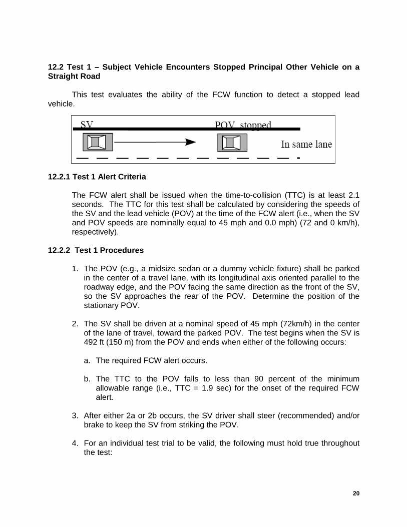
12.2 Test 1 – Subject Vehicle Encounters Stopped Principal Other Vehicle on a Straight Road This test evaluates the ability of the FCW function to detect a stopped lead vehicle.
12.2.1 Test 1 Alert Criteria
The FCW alert shall be issued when the time-to-collision (TTC) is at least 2.1 seconds. The TTC for this test shall be calculated by considering the speeds of the SV and the lead vehicle (POV) at the time of the FCW alert (i.e., when the SV and POV speeds are nominally equal to 45 mph and 0.0 mph) (72 and 0 km/h), respectively).
12.2.2 Test 1 Procedures
1. The POV (e.g., a midsize sedan or a dummy vehicle fixture) shall be parked in the center of a travel lane, with its longitudinal axis oriented parallel to the roadway edge, and the POV facing the same direction as the front of the SV, so the SV approaches the rear of the POV. Determine the position of the stationary POV.
2. The SV shall be driven at a nominal speed of 45 mph (72km/h) in the center
of the lane of travel, toward the parked POV. The test begins when the SV is 492 ft (150 m) from the POV and ends when either of the following occurs: a. The required FCW alert occurs.
b. The TTC to the POV falls to less than 90 percent of the minimum
allowable range (i.e., TTC = 1.9 sec) for the onset of the required FCW alert.
3. After either 2a or 2b occurs, the SV driver shall steer (recommended) and/or
brake to keep the SV from striking the POV. 4. For an individual test trial to be valid, the following must hold true throughout
the test:
21
a. The SV vehicle speed cannot deviate from the nominal speed by more than 1.0 mph (1.6 km/h) for a period of 3.0 seconds prior to (1) the required FCW alert or (2) before the range falls to less than 90 percent of the minimum allowable range for onset of the required FCW alert.
b. SV driver shall not apply any force to the brake pedal before the required FCW alert occurs, or before the range falls to less than 90 percent of the minimum allowable range for onset of the required FCW alert.
c. The lateral distance between the centerline of the SV, relative to the centerline of the POV, in road coordinates, cannot exceed 2.0 ft (0.6 m).
d. The yaw rate of the SV must not exceed ±1.0 deg/sec during the test.
5. Nominally, the Test 1 series is comprised of seven individual trials. The FCW
system must satisfy the TTC requirement of Section 12.2.1 for at least five of the seven test trials to successfully pass Test 1. If the first five of the seven individual test trials satisfy the Section 12.2.1 TTC requirement, it is not necessary to perform additional trials to verify that two consecutive failures not take place. If more than seven test trials are collected, only the first seven, valid trials will be considered for the Pass/Fail criterion.
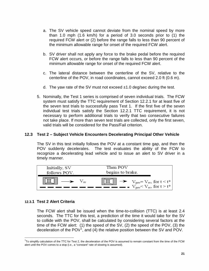
12.3 Test 2 – Subject Vehicle Encounters Decelerating Principal Other Vehicle
The SV in this test initially follows the POV at a constant time gap, and then the POV suddenly decelerates. The test evaluates the ability of the FCW to recognize a decelerating lead vehicle and to issue an alert to SV driver in a timely manner.
12.3.1 Test 2 Alert Criteria
The FCW alert shall be issued when the time-to-collision (TTC) is at least 2.4 seconds. The TTC for this test, a prediction of the time it would take for the SV to collide with the POV, shall be calculated by considering several factors at the time of the FCW alert: (1) the speed of the SV, (2) the speed of the POV, (3) the deceleration of the POV1, and (4) the relative position between the SV and POV.
1To simplify calculation of the TTC for Test 2, the deceleration of the POV is assumed to remain constant from the time of the FCW alert until the POV comes to a stop (i.e., a “constant” rate of slowing is assumed).
22
12.3.2 Test 2 Procedures
1. Test 2 begins with the SV and the POV traveling on a straight, flat road at a constant speed of 45 mph (72 km/h), in the center of the lane of travel. The headway from the SV to the POV shall be nominally maintained at 98.4 ft (30 m) until the POV braking is initiated.
2. Data collection shall begin approximately 7.0 seconds before the driver of the
POV starts a braking maneuver in which the POV brakes are rapidly applied and modulated such that a constant deceleration of 0.3 g is achieved no sooner than 1.0 seconds after the initiating breaking and prior to 1.5 seconds after braking is initiated. The test shall end when either of the following conditions is satisfied:
a. The required FCW alert occurs. b. The TTC to the POV falls to less than 90% of the minimum allowable
range (i.e., TTC = 2.2 sec) for the onset of the required FCW alert.
3. After either 2a or 2b occurs, the SV driver shall steer and/or brake to keep the SV from striking the POV.
4. For an individual test trial to be valid, the following must hold throughout the
test:
a. The initial POV vehicle speed cannot deviate from the nominal speed by more than 1.0 mph (1.6 km/h) for a period of 3.0 seconds prior to the initiation of POV braking.
b. Speed of the SV cannot deviate from the nominal speed by more than 1.0
mph (1.6 km/h) for a period of 3 seconds prior to (1) the required FCW alert or (2) before the range falls to less than 90 percent of the minimum allowable range for onset of the required FCW alert.
c. The lateral distance between the centerline of the SV, relative to the
centerline of the POV, in road coordinates, cannot exceed 2.0 ft (0.6 m).
d. The yaw rates of the SV and POV must not exceed ±1.0 deg/sec during the test.
e. The POV deceleration level shall nominally be 0.3 g no sooner than 1.0
seconds after the initiating breaking and prior to 1.5 seconds after initiation of POV braking. The acceptable error magnitude of the POV deceleration is ± 0.03g, measured at the time the FCW alert first occurs. An initial overshoot beyond the deceleration target is acceptable, however the first local deceleration peak observed during an individual trial must
23
not exceed 0.375 g for more than 50 ms. Additionally, the deceleration must not exceed 0.33 g over a period defined from (1) 500 ms after the first local deceleration peak occurs, to (2) the time when the FCW alert first occurs.
f. The tolerance for the headway from the SV to the POV shall be 98.4 ± 8.2
ft (30.0 ± 2.5 m), measured at two instants in time: (1) three seconds prior to the time the POV brake application is initiated, and (2) at the time the POV brake application is initiated.
g. A test is invalid if the SV driver applies any force to the brake pedal before
the required FCW alert occurs, or before the range falls to less than 90 percent of the minimum allowable range for onset of the required FCW alert.
5. Nominally, the Test 2 series is comprised of seven individual trials. The FCW
system must satisfy the TTC requirement of Section 12.3.1 for at least five of the seven test trials to successfully pass Test 2. If the first five of the seven individual test trials satisfy the Section 12.3.1 TTC requirement, it is not necessary to perform additional trials to verify that two consecutive failures not take place. If more than seven test trials are collected, only the first seven, valid trials will be considered for the Pass/Fail criterion.
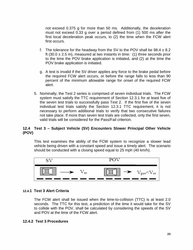
12.4 Test 3 – Subject Vehicle (SV) Encounters Slower Principal Other Vehicle (POV)
This test examines the ability of the FCW system to recognize a slower lead vehicle being driven with a constant speed and issue a timely alert. The scenario should be conducted with a closing speed equal to 25 mph (40 km/h).
12.4.1 Test 3 Alert Criteria
The FCW alert shall be issued when the time-to-collision (TTC) is at least 2.0 seconds. The TTC for this test, a prediction of the time it would take for the SV to collide with the POV, shall be calculated by considering the speeds of the SV and POV at the time of the FCW alert.
12.4.2 Test 3 Procedures
24
a) Throughout the test, the POV shall be driven at a constant 20 mph (32 km/h)
in the center of the lane of travel.
b) The SV shall be driven at 45 mph (72 km/h), in the center lane of travel, toward the slow-moving POV.
c) The test begins when the headway from the SV to the POV is 329 ft (100 m) and ends when either of the following occurs: a. The required FCW alert occurs.
b. The TTC to the POV falls to less than 90% of the minimum allowable
range (i.e., TTC = 1.8 sec) for the onset of the required FCW alert.
d) After either 3a or 3b occurs, the SV driver must then steer and/or brake to keep the SV from striking the POV.
e) For an individual test trial to be valid, the following must hold throughout the test: a. The SV vehicle speed cannot deviate from the nominal speed by more
than 1.0 mph (1.6 km/h) for a period of 3.0 seconds prior to (1) the required FCW alert or (2) before the range falls to less than 90 percent of the minimum allowable range for onset of the required FCW alert.
b. Speed of the POV cannot deviate from the nominal speed by more than 1.0 mph (1.6 km/h) during the test once it has reached 20 mph (32 km/h).
c. The lateral distance between the centerline of the SV, relative to the centerline of the POV, in road coordinates, cannot exceed 2.0 ft (0.6 m).
d. The yaw rates of the SV and POV must not exceed ±1.0 deg/sec during
the test.
e. A test is invalid if the SV driver applies any force to the brake pedal before the required FCW alert occurs, or before the range falls to less than 90 percent of the minimum allowable range for onset of the required FCW alert.
6. Nominally, the Test 3 series is comprised of seven individual trials. The FCW
system must satisfy the TTC requirement of Section 12.4.1 for at least five of the seven test trials to successfully pass the Test 3 evaluation criteria. If the first five of the seven individual test trials satisfy the Section 12.4.1 TTC requirement, it is not necessary to perform additional trials to verify that two consecutive failures not take place. If more than seven test trials are
25
collected, only the first seven, valid trials will be considered for the Pass/Fail criterion.
13.0 POST TEST REQUIREMENTS 13.1 Vehicle Data and Test Documentation
The Contractor shall collect all data necessary to complete the final test report data sheets and provide details of any problem areas.
13.2 Post Test Vehicle Inspection. The Contractor shall inspect the test vehicle after all testing is completed. Any vehicle modifications or damage shall be restored to the as-delivered condition or the vehicle shall be declared “totaled” and shall be disposed of as a totally destroyed vehicle. Disposition of the vehicle shall be determined by the Government. Any damage incurred to the vehicle during the actual tests, except damage caused by negligence of the Contractor, shall be the responsibility of the Government.
14.0 REPORTS 14.1 Monthly Status Reports
The Contractor shall submit a monthly Test Status Report and a Vehicle or Equipment Status Report to the COTR (both reports shown in this section). The Vehicle Status Report shall be submitted until all vehicles or items of equipment are disposed of.
14.2 Test Anomalies
In the event of an apparent test failure, a post-test calibration check of some critically sensitive test equipment and instrumentation may be required for verification of accuracy. The necessity for the calibration shall be at the COTR's discretion and shall be performed without additional costs to the OCAS.
14.3 Final Test Report 14.3.1 Copies
The Contractor shall provide the OCAS with one (1) CD per test. Two items shall be included on each CD: (1) a JPG of the vehicle in its test mode, taken with a resolution of at least 800 x 600 pixels, and (2) test video footage. In addition to the CD, the Contractor shall provide the OCAS with one paper copy
26
of each Final Test Report. The above documentation shall be submitted to the COTR according to the schedule indicated in Section 6.
Contractors are required to submit one color copy of each Final Test Report in draft form. DO NOT stamp preliminary or draft on this report. The COTR will review the draft report and notify the laboratory of any corrections that are required. If we agree to make changes to the test report, mail the appropriate (the changed) pages to us. We will insert the new pages into the preliminary test report. At the end, we will accept the preliminary test report with the inserted pages as the final test report.
14.3.2 Requirements
The Final Test Report, associated documentation (including photographs) is relied upon as the chronicle of the test. The Final Test Report will be released to the public domain after review and acceptance by the COTR. For these reasons, each final report must be a complete document capable of standing by itself.
The Contractor should use detailed descriptions of all test events. Any events that are not directly associated with the test program but are of technical interest should also be included. The Contractor should include as much detail as possible in the report.
Instructions for the preparation of the first three pages of the final test report are provided below for the purpose of standardization.
14.3.3 First Three Pages
27
Front Cover - - A heavy paperback cover (or transparency) shall be provided for the protection of the final report. The information required on the cover is as follows:
(A) Final Report Number such as OCAS-ABC-0X-001
Where: OCAS is the Office of Crash Avoidance Standards, ABC are the initials for the laboratory 0X is the Fiscal Year of the test program 001 is the Group Number (00 1 for the 1st test, 002 for the 2nd test, 003for the 3rd test, etc.)
(B) Final Report Title And Subtitle such as
Forward Collision Warning System Confirmation Test **************************************** World Motors Corporation 200X XYZ 4-door sedan NHTSA No. CX0401
(C) Contractor's Name and Address such as
XYZ TESTING LABORATORIES, INC. 4335 West Dearborn Street Detroit, Michigan 48090
NOTE: DOT SYMBOL WILL BE PLACED BETWEEN ITEMS (C) AND (D)
(D) Date of Final Report completion
(E) The words “FINAL REPORT”
(F) The sponsoring agency's name and address as follows
U. S. DEPARTMENT OF TRANSPORTATION National Highway Traffic Safety Administration Office of Crash Avoidance Standards Mail Code: NVS-120 1200 New Jersey Avenue SE, Room W43-478 Washington, DC 20590
28
First Page After Front Cover - - A disclaimer statement and an acceptance signature block for the COTR shall be provided as follows:
This publication is distributed by the U.S. Department of Transportation, National Highway Traffic Safety Administration, in the interest of information exchange. The opinions, findings and conclusions expressed in this publication are those of the author(s) and not necessarily those of the Department of Transportation or the National Highway Traffic Safety Administration. The United States Government assumes no liability for its contents or use thereof. If trade or manufacturers' names or products are mentioned, it is only because they are considered essential to the object of the publication and should not be construed as an endorsement. The United States Government does not endorse products or manufacturers.
Prepared By: _____________________________________
Approved By: _____________________________________
Approval Date: _____________________________________
29
Second Page After Front Cover - - A completed Technical Report Documentation Page (Form DOT F1700.7) shall be completed for those items that are applicable with the other spaces left blank. Sample data for the applicable block numbers of the title page follows.
Block No. 1 - - REPORT NUMBER
OCAS-ABC-0X-001
Block No. 2 - - GOVERNMENT ACCESSION NUMBER
Leave blank
Block No. 3 - - RECIPIENT'S CATALOG NUMBER
Leave blank
Block No. 4 - - TITLE AND SUBTITLE
Final Report of Forward Collision Warning Testing of a 200X World XYZ Deluxe 4-door sedan NHTSA No. CX0401
Block No. 5 - - REPORT DATE
March 1, 200X
Block No. 6 - - PERFORMING ORGANIZATION CODE
ABC
Block No. 7 - - AUTHOR(S)
John Smith, Project Manager Bill Doe, Project Engineer
Block No. 8 - - PERFORMING ORGANIZATION REPORT NUMBER
ABC-DOT-XXX-001
Block No. 9 - - PERFORMING ORGANIZATION NAME AND ADDRESS
ABC Laboratories 405 Main Street Detroit, Ml 48070
30
Block No. 10 - - WORK UNIT NUMBER
Leave blank
Block No. 11 - - CONTRACTOR GRANT NUMBER
DTNH22-0X-D-1 2345
Block No. 12 - - SPONSORING AGENCY NAME AND ADDRESS
U. S. DEPARTMENT OF TRANSPORTATION National Highway Traffic Safety Administration Office of Crash Avoidance Standards Mail Code: NVS-120 1200 New Jersey Avenue SE, Room W43-478 Washington, DC 20590
Block No. 13 - - TYPE OF REPORT AND PERIOD COVERED
Final Test Report XXX to XXX, 200X
Block No. 14 - - SPONSORING AGENCY CODE
NVS-120
Block No. 15 - - SUPPLEMENTARY NOTES
Leave blank
Block No. 16 - - ABSTRACT
These tests were conducted on the subject 200X World XYZ 4-door sedan in accordance with the specifications of the Office of Crash Avoidance Standards Test Procedure No. TP-OCAS-XX for the confirmation of a forward collision warning system.
Block No. 17 - - KEY WORDS
Forward Collision Warning, FCW
Block No. 18 - - DISTRIBUTION STATEMENT
Copies of this report are available from the following:
NHTSA Technical Reference Division National Highway Traffic Safety Administration 1200 New Jersey Avenue SE, Washington, DC 20590
31
Block No. 19 - - SECURITY CLASSIFICATION OF REPORT
Unclassified
Block No. 20 - - SECURITY CLASSIFICATION OF PAGE
Unclassified
Block No. 21 - - NO. OF PAGES
Add appropriate number
Block No. 22 - - PRICE
Leave blank 14.3.4 TABLE OF CONTENTS .......................................................................... PAGE NO.
Sample Test Report Table of Contents: A. Section 1 — Purpose and Summary of Test B. Section 2 — Vehicle Information/Data Sheets C. Section 3 — Photographs D. Section 4 — Vehicle data traces. E. Section 5 — Test Equipment and Instrumentation Calibration
14.3.5 SAMPLE TEST REPORT INFORMATION
PURPOSE AND SUMMARY OF TEST
PURPOSE
This test is part of the Crash Avoidance program to assess Forwardl Collision Warning Systems
sponsored by the National Highway Traffic Safety Administration (NHTSA) under Contract
No.___________. The purpose of this test was to obtain vehicle crash avoidance performance data for
_________.
32
SUMMARY
DATA SHEET NO. DESCRIPTION
1. Test Summary
2. General Test and Vehicle Parameter Data
3. Post test Data
4. Test Vehicle Information
5. Vehicle Measurements
33
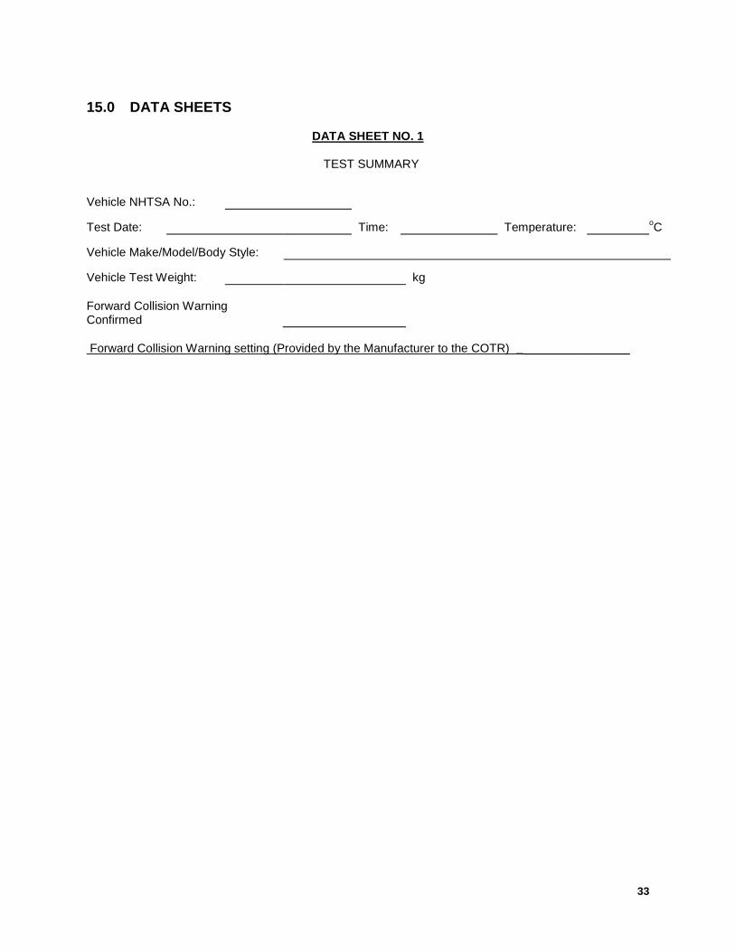
15.0 DATA SHEETS
DATA SHEET NO. 1
TEST SUMMARY
Vehicle NHTSA No.:
Test Date: Time: Temperature: oC
Vehicle Make/Model/Body Style:
Vehicle Test Weight: kg Forward Collision Warning Confirmed Forward Collision Warning setting (Provided by the Manufacturer to the COTR) _________________
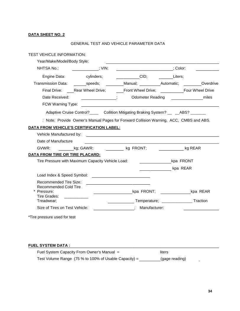
34
DATA SHEET NO. 2
GENERAL TEST AND VEHICLE PARAMETER DATA TEST VEHICLE INFORMATION:
Year/Make/Model/Body Style:
NHTSA No.: ; VIN: ; Color:
Engine Data: cylinders; CID; Liters;
Transmission Data: speeds; Manual; Automatic; Overdrive
Final Drive: Rear Wheel Drive; Front Wheel Drive; Four Wheel Drive
Date Received: ; Odometer Reading miles
FCW Warning Type:
Adaptive Cruise Control?____ Collition Mitigating Braking System? __ __ABS? _______
: Note: Provide Owner’s Manual Pages for Forward Collision Warning, ACC, CMBS and ABS.
DATA FROM VEHICLE'S CERTIFICATION LABEL: Vehicle Manufactured by:
Date of Manufacture
GVWR: kg; GAWR: kg FRONT; kg REAR DATA FROM TIRE OR TIRE PLACARD: Tire Pressure with Maximum Capacity Vehicle Load: kpa FRONT
kpa REAR
Load Index & Speed Symbol:
Recommended Tire Size:
* Recommended Cold Tire Pressure: kpa FRONT; kpa REAR
Tire Grades: ___________ Treadwear; Temperature; ______________ Traction
Size of Tires on Test Vehicle: ; Manufacturer: *Tire pressure used for test
FUEL SYSTEM DATA : Fuel System Capacity From Owner's Manual = liters Test Volume Range (75 % to 100% of Usable Capacity) = (gage reading)

35
DATA SHEET NO. 3 Wind Speed at start of test series: _______________
PHOTOGRAPHS
36
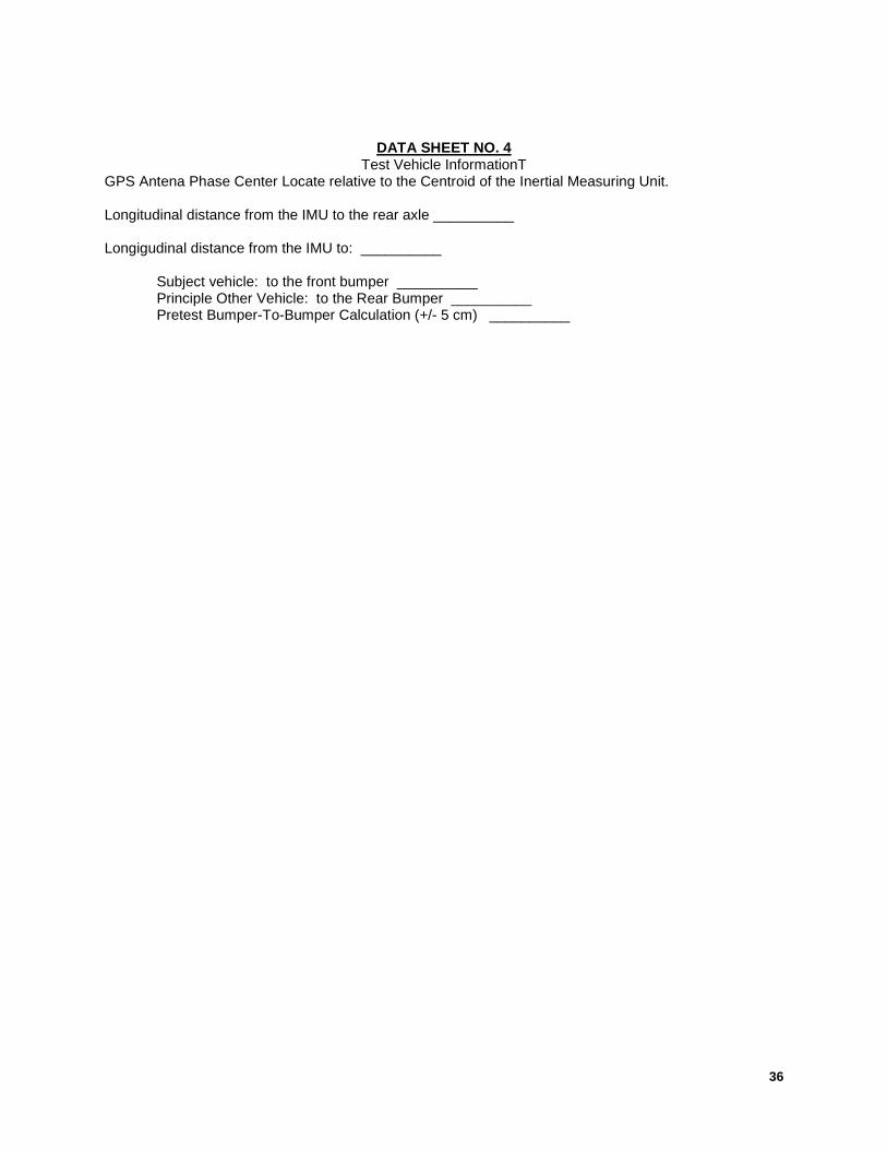
DATA SHEET NO. 4
Test Vehicle InformationT GPS Antena Phase Center Locate relative to the Centroid of the Inertial Measuring Unit. Longitudinal distance from the IMU to the rear axle __________ Longigudinal distance from the IMU to: __________ Subject vehicle: to the front bumper __________ Principle Other Vehicle: to the Rear Bumper __________ Pretest Bumper-To-Bumper Calculation (+/- 5 cm) __________
37
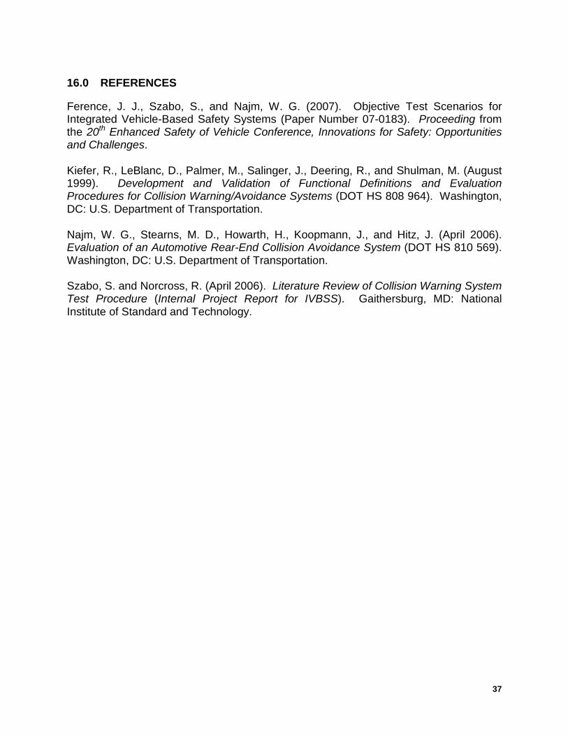
16.0 REFERENCES Ference, J. J., Szabo, S., and Najm, W. G. (2007). Objective Test Scenarios for Integrated Vehicle-Based Safety Systems (Paper Number 07-0183). Proceeding from the 20th Enhanced Safety of Vehicle Conference, Innovations for Safety: Opportunities and Challenges. Kiefer, R., LeBlanc, D., Palmer, M., Salinger, J., Deering, R., and Shulman, M. (August 1999). Development and Validation of Functional Definitions and Evaluation Procedures for Collision Warning/Avoidance Systems (DOT HS 808 964). Washington, DC: U.S. Department of Transportation. Najm, W. G., Stearns, M. D., Howarth, H., Koopmann, J., and Hitz, J. (April 2006). Evaluation of an Automotive Rear-End Collision Avoidance System (DOT HS 810 569). Washington, DC: U.S. Department of Transportation. Szabo, S. and Norcross, R. (April 2006). Literature Review of Collision Warning System Test Procedure (Internal Project Report for IVBSS). Gaithersburg, MD: National Institute of Standard and Technology.
38
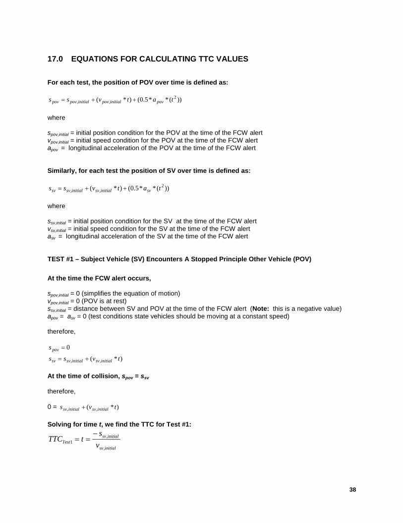
17.0 EQUATIONS FOR CALCULATING TTC VALUES For each test, the position of POV over time is defined as:
))(**5.0()*( 2,, tatvss povinitialpovinitialpovpov ++=
where spov,initial = initial position condition for the POV at the time of the FCW alert vpov,initial = initial speed condition for the POV at the time of the FCW alert apov = longitudinal acceleration of the POV at the time of the FCW alert Similarly, for each test the position of SV over time is defined as:
))(**5.0()*( 2,, tatvss svinitialsvinitialsvsv ++=
where ssv,initial = initial position condition for the SV at the time of the FCW alert vsv,initial = initial speed condition for the SV at the time of the FCW alert asv = longitudinal acceleration of the SV at the time of the FCW alert TEST #1 – Subject Vehicle (SV) Encounters A Stopped Principle Other Vehicle (POV)
At the time the FCW alert occurs, spov,initial = 0 (simplifies the equation of motion) vpov,initial = 0 (POV is at rest) ssv,initial = distance between SV and POV at the time of the FCW alert (Note: this is a negative value) apov = asv = 0 (test conditions state vehicles should be moving at a constant speed) therefore,
0=povs
)*( ,, tvss initialsvinitialsvsv += At the time of collision, spov = ssv therefore, 0 = )*( ,, tvs initialsvinitialsv + Solving for time t, we find the TTC for Test #1:
initialsv
initialsvTest v
stTTC
,
,1
−==
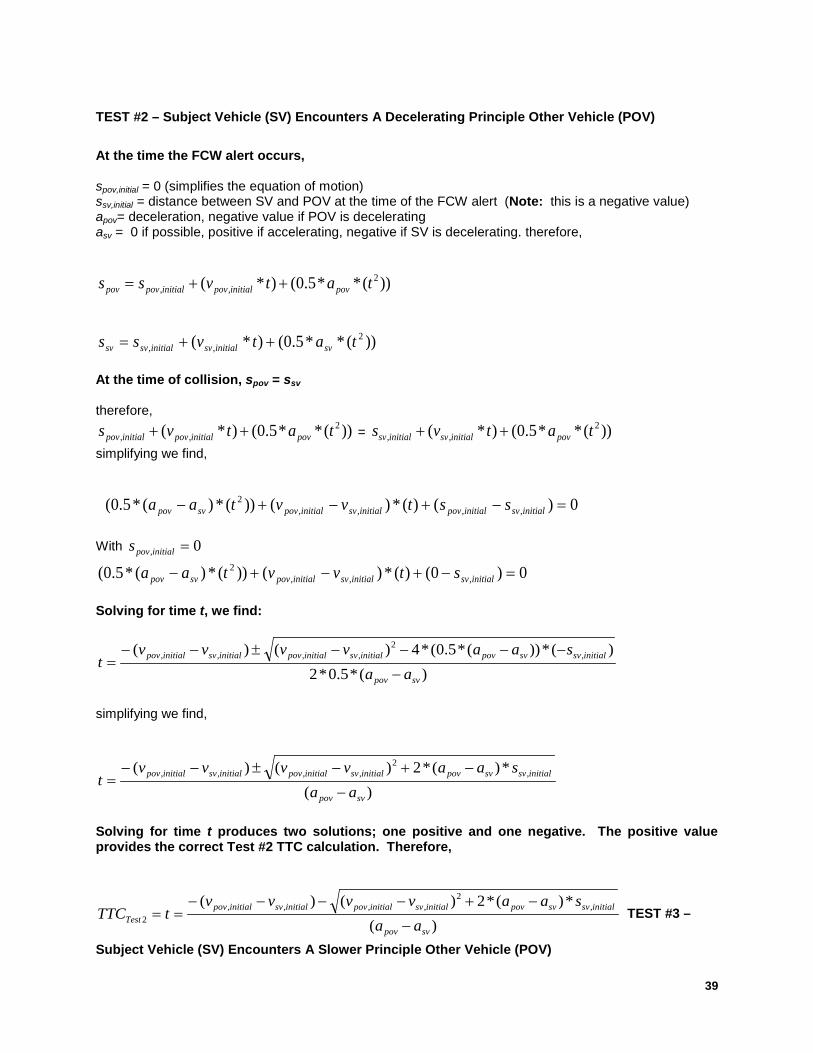
39
TEST #2 – Subject Vehicle (SV) Encounters A Decelerating Principle Other Vehicle (POV)
At the time the FCW alert occurs, spov,initial = 0 (simplifies the equation of motion) ssv,initial = distance between SV and POV at the time of the FCW alert (Note: this is a negative value) apov= deceleration, negative value if POV is decelerating asv = 0 if possible, positive if accelerating, negative if SV is decelerating. therefore,
))(**5.0()*( 2,, tatvss povinitialpovinitialpovpov ++=
))(**5.0()*( 2,, tatvss svinitialsvinitialsvsv ++=
At the time of collision, spov = ssv therefore,
))(**5.0()*( 2,, tatvs povinitialpovinitialpov ++ = ))(**5.0()*( 2
,, tatvs povinitialsvinitialsv ++ simplifying we find, 0)()(*)())(*)(*5.0( ,,,,
2 =−+−+− initialsvinitialpovinitialsvinitialpovsvpov sstvvtaa With 0, =initialpovs
0)0()(*)())(*)(*5.0( ,,,2 =−+−+− initialsvinitialsvinitialpovsvpov stvvtaa
Solving for time t, we find:
)(*5.0*2)(*))(*5.0(*4)()( ,
2,,,,
svpov
initialsvsvpovinitialsvinitialpovinitialsvinitialpov
aasaavvvv
t−
−−−−±−−=
simplifying we find,
)(*)(*2)()( ,
2,,,,
svpov
initialsvsvpovinitialsvinitialpovinitialsvinitialpov
aasaavvvv
t−
−+−±−−=
Solving for time t produces two solutions; one positive and one negative. The positive value provides the correct Test #2 TTC calculation. Therefore,
)(*)(*2)()( ,
2,,,,
2svpov
initialsvsvpovinitialsvinitialpovinitialsvinitialpovTest aa
saavvvvtTTC
−
−+−−−−== TEST #3 –
Subject Vehicle (SV) Encounters A Slower Principle Other Vehicle (POV)
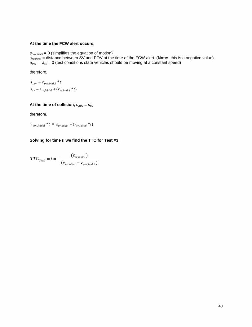
40
At the time the FCW alert occurs, spov,initial = 0 (simplifies the equation of motion) ssv,initial = distance between SV and POV at the time of the FCW alert (Note: this is a negative value) apov = asv = 0 (test conditions state vehicles should be moving at a constant speed) therefore,
tvs initialpovpov *,=
)*( ,, tvss initialsvinitialsvsv += At the time of collision, spov = ssv therefore,
tv initialpov *, = )*( ,, tvs initialsvinitialsv + Solving for time t, we find the TTC for Test #3:
)()(
,,
,3
initialpovinitialsv
initialsvTest vv
stTTC
−−==