Embed Size (px)
Citation preview

Proceedings of the 6th International Mining and Industrial Waste Management Conference,
29, 30 & 31 October 2018 – Legend Golf and Safari Resort, Limpopo
1
Selati Tailings Dam New Decant Tower
A. J. Strauss1 1Knight Piésold Consulting, Sandton, Gauteng, [email protected]
Abstract
A failure occurred along the Selati Tailings Dam decant outlet conduit in February 2013.
Emergency response procedures ensured the integrity of the facility. Improved engineered
remedial measures were then executed. A trade-off study was conducted to find the preferred
option for replacement of the decant system. The outcome was that a gravity decant system
similar to the existing system is preferred and is to be located on natural ground in the facility
basin on the Southern side. The detail design was prepared for this 64 m tall concrete structure
and standalone hybrid staircase. The system can be operated fully remotely and uses power
delivered by batteries, charged from solar panels on the control room roof. Engineering support
services and quality control services were provided during the complicated construction phase
and various innovations applied. The system is complete, commissioned and fully operation.
Keywords: Trade-off, decant, design, engineering support.
1 Introduction
Foskor’s Phalaborwa operation offices are located in the Limpopo Province, South West of the
Phalaborwa town. The Selati Tailings Dam (STD) is located approximately at coordinates
24°02’ South and 31°06’ East, North of the Olifants River as indicated in Figure 1 below. The
new decant tower is located on the southern part of the STD.

6th IMIWM Conference 2018
2
Figure 1. Selati Tailings Dam Location.
The Client appointed consulting engineers to carry out the design of the new decant tower
system for the Selati Tailings Dam (STD) at Foskor Phalaborwa following the failure of the
existing main decant outfall conduit in Feb 2013.
A trade-off study was completed in May 2013 to determine the optimum decanting solution for
the STD to the end of 2050. Options considered included gravity decants, pumped decanting
and siphoning. The preferred option was for a gravity decant tower of similar design to the old
tower.
The new tower structure was positioned on the southern part of the tailings dam, on the only
remaining natural ground within the TD basin. The decant pipe will gravitate supernatant water
and process water from the tailings dam to the outlet where it will report into the existing return
water dam (RWD) via an energy dissipator.
2 Trade-off
Various decant options were considered during the trade-off study, which included gravity,
pumping, floating barge and siphoning options or combination thereof. A trade-off matrix
system was used to weigh each option based on technical issues, economic issues and physical
environmental aspects. The gravity decant system with its decant tower positioned on the south
side of the Selati tailings dam obtained the highest score in the matrix and was therefore the
recommended decant option.

A. J. Strauss
3
3 Detail Design
The concrete tower is 64 m tall and was designed with a circular concrete base. It has four
decant flow channels which will decant water from the pond on rotational basis. Each channel
has 35 flow tubes that will be used during the operational life of the tower system. The unused
tubes are pegged on the guard rail and as the pond level rises, the pegged tube will be dropped
manually to become the next tube to decant water. The decant system can operate automatically
without any human interference. The suspended platform, which is operated in the control
room at the upper end of the tower, will be used to access the flow tube channels. The mild
steel / stainless steel hybrid standalone staircase provides access to the suspended platform and
control room.
3.1 Geotechnical aspects The geotechnical site investigation included excavation of a number of test pits along the outlet
pipe alignment and drilling of two rotary core drill holes in the tower area to investigate
foundation conditions.
A number of samples were taken for laboratory testing. Laboratory testing comprised indicator
tests (i.e. Gradings and Atterberg limits), determination of the compaction properties (i.e.
Modified AASHTO maximum dry density tests and optimum moisture content) and California
Bearing Ratio tests.
A site visit to the southern open pit at the mine was conducted to inspect the available dolerite
rock material from the mining operations. Cored rock samples were taken from the drilled
boreholes to determine the strength properties of the rock, i.e. Uniaxial Compressive Strength
(UCS) tests and Uniaxial Compressive Strength tests with deformation measurements (UCM).
At the tower foundation position, very soft granite gneiss rock was encountered between the
depth of between 2.4 m and 2.9 m in the drill holes. The granite-gneiss rock was found to be
typically highly weathered, interlayered with very soft and soft rock, with an allowable bearing
capacity of 750 kPa which exceeds 650 kPa required by the early design. It was therefore
recommended that the tower should be founded at a depth of between 2.4 m and 2.9 m.
The design required Y32 dowels bars to be grouted into bedrock and cast into the tower base to
improve stability.
As the design developed, it became apparent that a bearing capacity of 1 000 kPa was required.
This necessitated a founding depth of between 5.3 m and 5.8 m. The outlet pipe line and
associated 27 m deep cut had already been finalized by this time. Since the system could not be
lowered this late in the design the void between the new founding level and the tower base was
filled with mass concrete to form a plinth together with the dowels grouted and cast in.
3.2 Main structure The structure was analysed using AUTODESK ROBOT STRUCTURAL ANALYSIS
PROFESSIONAL 2014 (Robot). Robot is a structural analysis software package that uses
Finite Element Analysis (FEA) to analyse concrete and steel structures.
The structure was designed to the General Engineering Specifications of Foskor Limited and
adhere to the following design standards:
• SANS 10100:2000
• SANS 10160: 2011
• SANS 10162: 2005
• EN1993-1-8:2005

6th IMIWM Conference 2018
4
The design accounted for dead load (both the structure and mechanical equipment), live load,
wind load, tailings down-drag and temperature loading. Various loading combinations were
considered in accordance with SANS 10160-1:2011.
The following aspects were modelled and assessed: bending, shear, axial compression,
deflection and slenderness.
3.3 Access A platform providing access to the operational flow tubes is suspended just above the water
level. The platform is raised to remain above the rising water level.
On the existing tower, access to the control room at the top of the tower was provided via 9 m
sections of vertically mounted cat ladders, accessed from the suspended platform, with a safety
cage providing fall protection. Intermediate platforms were provided between each 9 m section.
Following a Risk Assessment, it was decided that the cat ladder system is not suitable to be
used on the new tower, primarily based on health and safety concerns.
The first alternative design considered a spiral staircase. Because the suspended platform has
to be able to be operated from water level to the control room, the staircase central circular
column could not be fixed to the concrete tower. Access from the staircase onto the platform
would also only be possible where the stairs are adjacent to the platform. The central column
in this concept proved to be too slender and this concept was abandoned.
The second concept was that of an elevator system. It would be battery driven and all safety
aspects were given due consideration. This concept would require low capital expenditure and
minimal operating cost. It was rejected by the client due to the rigorous inspection requirements
of the DMR. They felt that the risk of non-conformances with the elevator causing stoppages
on the rest of the mine outweighed the financial benefit of the system.
A. J. Strauss
5
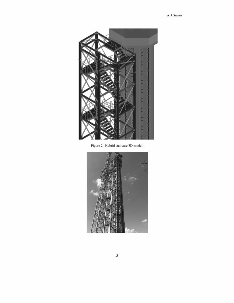
Figure 2. Hybrid staircase 3D-model.

6th IMIWM Conference 2018
6
Figure 3. Hybrid staircase under construction.
The third design concept employed a more conventional steel staircase structure. Again, the
structure had to be completely free standing to allow the free movement of the suspended
platform. The structure would also be inundated by the supernatant pool and deposited tailings
over time. The structure was designed to withstand these conditions for at least the expected 37
year life of the tower.
The lower two thirds of the six main support columns are constructed from stainless steel, while
corrosion protected mild steel was used for the upper third. This minimises the risk of corrosion
of the members that could lead to failure of the structure. The upper third will be exposed to
harsh conditions for a shorter period of time and was for that reason constructed in mild steel,
resulting in a cost saving over stainless steel.
3.4 Pipe line The design criteria required a maximum flow rate in the outlet system of 0.9 m3/s.
The first 740 m of the 900 mm diameter concrete outlet pipe line was constructed in a cutting
of up to 27 m deep, to ensure gravity discharge. The remaining 2 340 m of outlet pipe was
constructed using an 800 mm diameter mild steel pipe line, placed above ground on precast
concrete sleepers.
The concrete section of the outlet which will become buried under tailings with time comprise
900 mm diameter precast concrete spigot and socket pipes, used as a void former, encased in
reinforced concrete of 1.2 x 1.2 m dimensions. This section of the outlet was designed to
withstand the load of the tailings to the expected height of some 60 m to be reached in 37 years.
At the daylight point where the pipe line transitions from concrete to steel, an isolation valve
was provided, able to withstand the maximum pressure head possible at the end of life of the
tower. Operation of this valve will allow the mine to curtail flow of water and solids in the pipe
line in case of a failure, thus preventing release of solids from the tailings dam.
The steel pipe line section was specified to be 800 ND Steel, 6 mm wall thickness with internal
and external corrosion protection (Nordbak Nordcoat 6). The pipe route was aligned on the
outer slopes of the tailings dam, aiming to follow the contours and maintain an even slope as
much as practicable.
Air release valves were provided in key locations and concrete thrust blocks on all bends. An
energy dissipator was provided on the outlet of the pipe line to allow discharge into the return
water dam that will not damage or erode the dam wall.
4 Construction
The client appointed the consulting engineers to oversee the Quality Control/Quality Assurance
(QC/QA) aspects during the construction phase of the new decant system and to provide
engineering support.
QC refers to the following:
Those actions taken by the Contractor’s team (or their subcontractors) to determine
compliance of the various components of the excavation, materials and equipment
sourcing, construction, installation, backfill, testing and commissioning activities
with the requirements of the approved design; and

A. J. Strauss
7
QA refers to the following:
Means and actions to independently assess conformity of the various components of
the excavation, materials and equipment sourcing, construction, installation, backfill,
testing and commissioning activities with the requirements of the approved design.
Engineering support services:
Addressing and technical matters arising during the construction process, performing
design check or changes and amending construction drawings accordingly.
These tasks were complicated by the client dividing the project into three separate contracts.
These were 1) the decant tower, 2) the sub-surface outfall pipe line and 3) the surface outfall
pip line.
The following tasks were carried out on all three contracts: issuing of updated construction
drawings and maintaining the drawing register, inspection and verification, commissioning and
documenting and reporting.
The quality of the construction, installation and commissioning of the new decant system met
the set standards, design specifications and performance objectives. The system was therefore
declared ready for operation.
5 Innovations
A number of innovations were applied during the design phase and post start of construction
works. A few are discussed in this section.
5.1 Hydropower concept During the design, a conceptual hydro power generation system was considered. To facilitate
implementation, the outlet pipe lines would have required a redesign, to upgrade them from
gravity lines to pressure lines. The client chose not to implement the system.
The design considered a flow range of 0.45 – 0.9 m3/s. A crossflow type turbine with
asynchronous generator was considered, operational at 80% efficiency over the full flow range.
It was estimated that 2 472 – 2 966 MWh/a could have been generated. Considering the
construction cost and electrical tariffs, an IRR of 36.6% was estimated.
5.2 Temporary pump tie-in The temporary pump system which had been in operation since the failure in early 2013, had
limited capacity due to the small diameter decant pipe. Tying into the new decant outlet pipe
line earlier allowed for increased decanting from the facility.
This was made possible by the provision of a sweep-tee inlet, tying into the steel section of the
outlet pipe near chainage 1 200 m. Once the pipe line from this point to the RWD had been
completed, this inlet was commissioned.
Figure 4. Sweep-Tee pumped decant inlet.

6th IMIWM Conference 2018
8
5.3 Side inlet At the time of completion of the decant system, the water level in the tailings dam was still
approximately 2 m below the first intake level. As the mine was actively trying to reduce the
pond volume and in the process of increasing the capacity of their beach irrigation system, it
was challenging to estimate the time it would take for the water level to rise sufficiently to start
decanting through the new tower.
The sooner this condition could be achieved, the sooner the costly pumping system can be
decommissioned. To achieve this condition sooner, a side-inlet structure was designed and
constructed at chainage 50 m along the concrete section of the outlet.
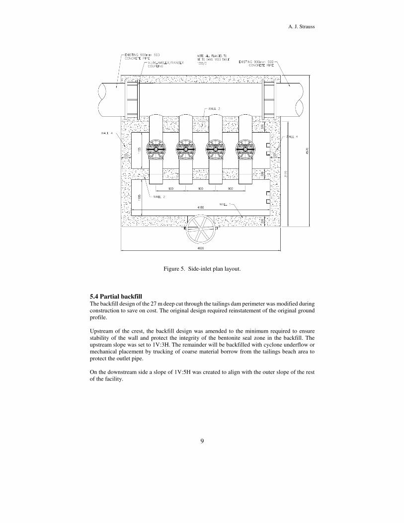
The inlet structure was design as a two-compartment structure. The inlet was fitted with a
stainless-steel sluice gate, allowing control of flow into the first chamber. 4 No. 450 mm
diameter pipes were installed through the chamber wall. Knife gate valves were installed to
control the flow through individual inlets. A special insert was manufactured and installed into
the concrete line, allowing flow through the four inlets, into the outlet pipe line. This special
was then cast into the concrete encasement, like the rest of the concrete pipe section.
Once the tower flow tubes are decanting at a sufficiently high flow rate, the side-inlet will be
decommissioned and filled with mass concrete.
A. J. Strauss
9
Figure 5. Side-inlet plan layout.
5.4 Partial backfill The backfill design of the 27 m deep cut through the tailings dam perimeter was modified during
construction to save on cost. The original design required reinstatement of the original ground
profile.
Upstream of the crest, the backfill design was amended to the minimum required to ensure
stability of the wall and protect the integrity of the bentonite seal zone in the backfill. The
upstream slope was set to 1V:3H. The remainder will be backfilled with cyclone underflow or
mechanical placement by trucking of coarse material borrow from the tailings beach area to
protect the outlet pipe.
On the downstream side a slope of 1V:5H was created to align with the outer slope of the rest
of the facility.

6th IMIWM Conference 2018
10
Figure 6. Typical section of the backfill design.
6 Conclusion
The consulting engineers demonstrated technical excellence throughout by supporting the client
at each step along the way from addressing the emergency situation through to commissioning
of the new decant system. An automatically operated decant system including tower, access
staircase and outlet pipes were constructed on geotechnically improved ground while
optimizing the backfill earthworks to reduce capital expenditure. Innovations were applied to
reduce operational expenditure during the transition to the new system becoming fully
operational. A hydropower system was also proposed.
7 Acknowledgements
The author expresses his thanks to the client: Foskor Limited Phalaborwa and to the consulting
engineers Knight Piésold for permission to publish this paper.
References
Loubser, A. L. and Strauss, A. J. 2018. Foskor Selati TSF – New decant system – Construction
QA Report.
Knight Piésold Report RI301-00055/85-R1
Louwinger, F. and Lillie, E. 2014. Hydropower concept in the Selati dam decant system.
Knight Piésold.
Strauss, A. J. and Grant-Stuart, D. J. 2013. Selati tailings dam decant system trade-off study.
Knight Piésold Report RI301-55/51-R1
Strauss, A. J., Mazibuko, M. and Wilding, S. 2016. Selati decant tower design report.
Knight Piésold Report RI301-00055/54/R1


![OLD MUTUAL TWO OCEANS 2019 TOP ATHLETES’ PROFILES · TOP ATHLETES’ PROFILES ULTRAMARATHON MEN LOVEMORE CHABATA (39) [Zimbabwe] ... 9th in Foskor Half Marathon, Phalaborwa (66:54)](https://img.pdfslide.net/doc/110x75/5f17d6f87af273798c48a0b6/old-mutual-two-oceans-2019-top-athletesa-profiles-top-athletesa-profiles-ultramarathon.jpg)