Embed Size (px)
Citation preview
Fouling and Cleaning of a Staggered, Finned TubeBundle Under Coal-Fired Conditions
B.A. Allmon and G.B. WatsonBabcock & Wilcox Company
Research and Development DivisionAlliance, Ohio 44601
and
N.N. CarpenterHudson Products Corporation
Houston, Texas 77036
Presented at the National Heat Transfer Conference
RDTPA 91-11
Minneapolis, MinnesotaJuly 28-31, 1991
Hudson Products Corporation Page 2 of 15Houston, Texas Fouling and Cleaning of a Staggered, Finned Tube Bundle
Under Coal Fired Conditions
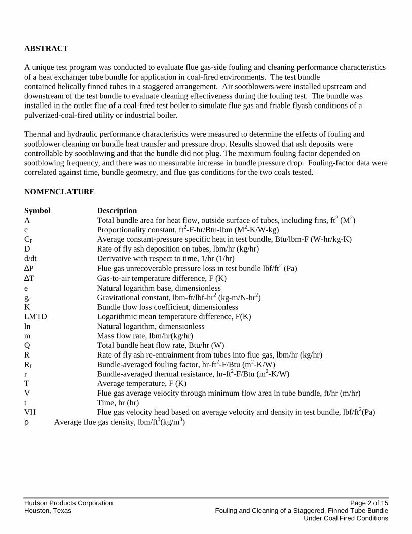
ABSTRACT
A unique test program was conducted to evaluate flue gas-side fouling and cleaning performance characteristicsof a heat exchanger tube bundle for application in coal-fired environments. The test bundlecontained helically finned tubes in a staggered arrangement. Air sootblowers were installed upstream anddownstream of the test bundle to evaluate cleaning effectiveness during the fouling test. The bundle wasinstalled in the outlet flue of a coal-fired test boiler to simulate flue gas and friable flyash conditions of apulverized-coal-fired utility or industrial boiler.
Thermal and hydraulic performance characteristics were measured to determine the effects of fouling andsootblower cleaning on bundle heat transfer and pressure drop. Results showed that ash deposits werecontrollable by sootblowing and that the bundle did not plug. The maximum fouling factor depended onsootblowing frequency, and there was no measurable increase in bundle pressure drop. Fouling-factor data werecorrelated against time, bundle geometry, and flue gas conditions for the two coals tested.
NOMENCLATURE
Symbol DescriptionA Total bundle area for heat flow, outside surface of tubes, including fins, ft2 (M2)c Proportionality constant, ft2-F-hr/Btu-Ibm (M2-K/W-kg)CP Average constant-pressure specific heat in test bundle, Btu/lbm-F (W-hr/kg-K)D Rate of fly ash deposition on tubes, lbm/hr (kg/hr)d/dt Derivative with respect to time, 1/hr (1/hr)∆P Flue gas unrecoverable pressure loss in test bundle lbf/ft2 (Pa)∆T Gas-to-air temperature difference, F (K)e Natural logarithm base, dimensionlessgc Gravitational constant, lbm-ft/lbf-hr2 (kg-m/N-hr2)K Bundle flow loss coefficient, dimensionlessLMTD Logarithmic mean temperature difference, F(K)ln Natural logarithm, dimensionlessm Mass flow rate, lbm/hr(kg/hr)Q Total bundle heat flow rate, Btu/hr (W)R Rate of fly ash re-entrainment from tubes into flue gas, lbm/hr (kg/hr)Rf Bundle-averaged fouling factor, hr-ft2-F/Btu (m2-K/W)r Bundle-averaged thermal resistance, hr-ft2-F/Btu (m2-K/W)T Average temperature, F (K)V Flue gas average velocity through minimum flow area in tube bundle, ft/hr (m/hr)t Time, hr (hr)VH Flue gas velocity head based on average velocity and density in test bundle, lbf/ft2(Pa)ρ Average flue gas density, lbm/ft3(kg/m3)

Hudson Products Corporation Page 3 of 15Houston, Texas Fouling and Cleaning of a Staggered, Finned Tube Bundle
Under Coal Fired Conditions
Subscripts
a Airavg Averagec Clean bundle or cold end of bundle (flue gas outlet)f Fouledg Flue gash Hot end of bundle (flue gas inlet)i Inleto Outlet
INTRODUCTION
Staggered tube bundles with pin (or stud) fins were introduced to the utility industry in the early 1960s as aneconomical heat transfer surface for economizers in coal-fired boilers. But after operating these units for a fewmonths, high-pressure drop resulted from ash plugging flow passages within the tube bundle. This reducedboiler load and power output of the plant. Due to these operational problems, it has become standard practice touse in-line arrangements either with or without finned extended surface, instead of the more compact, staggered,tube bundle arrangements.
In re-examining past experience, we found that the major fault in applying the staggered, finned, bundlearrangement to economizers was not in the bundle design but in the bundle location in the convective section ofthe boiler. The economizer is the last convective beat transfer surface in the boiler, and when placed in adown-pass section, it is below the other convective surfaces (reheater and superheater). With this design, largefly ash or slag particles that accumulate and dislodge from the upper heat transfer surface fall onto theeconomizer and eventually plug the compact surface. The particles are significantly larger than typical fly ash(5 to 500 microns) and become trapped in the extended surface and in the gaps between tubes. Therefore, pastand present experience suggests that compact, staggered, finned tube bundles can be a viable design alternativefor coal-fired boilers when they are not installed as economizers in down-pass sections of boilers. Compactbundles may be used in the fluegas downstream of boiler outlets where installations prevent large particles of flyash or slag from entering the bundle.
Experimental studies by Bemrose, et al. (1984), Portyanko, et al. (1980), and Lokshin, et al. (1980), also showedthat staggered, finned tube bundles can be used in ash-laden flow streams when the size of the ash is small andtypical of that expected in coal-fired boilers. Results presented by Portyanko, et al. (1980), even showed thatwith finned extended surfaces, the staggered tube arrangement can result in less fouling than the in-linearrangement. Their data also showed that fouling factor increased with more extended surface area anddecreased with higher gas velocity, regardless of bundle geometry. However, the effect of conventionalcleaning equipment, such as sootblowers and air lances, on controlling ash deposits was not reported. Acomprehensive compilation of related work is provided by Marner (1990).
This paper presents results of an experimental program conducted by the Babcock & Wilcox Co. (B&W) at itsAlliance (Ohio) Research Center to establish the flue gas-side heat transfer and pressure drop characteristics of astaggered, helically finned tube bundle under coal-fired conditions. The purposes of these relatively short-termtests were to demonstrate that a compact, staggered tube bundle would not plug and that sootblowers could beused to control the fouling process in a fly-ash-laden flue gas.
In selecting the appropriate staggered tube bundle geometry for this study, the number of tube rows deep and thegap between finned tubes were chosen based on guidelines for standard sootblowing upstream and downstream
Hudson Products Corporation Page 4 of 15Houston, Texas Fouling and Cleaning of a Staggered, Finned Tube Bundle
Under Coal Fired Conditions
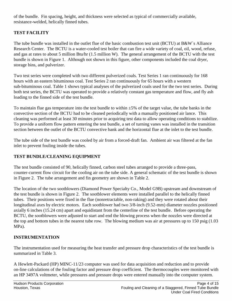
of the bundle. Fin spacing, height, and thickness were selected as typical of commercially available,resistance-welded, helically finned tubes.
TEST FACILITY
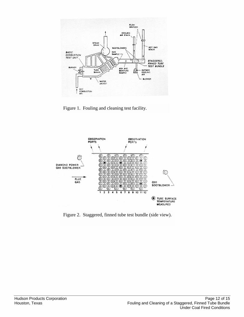
The tube bundle was installed in the outlet flue of the basic combustion test unit (BCTU) at B&W`s AllianceResearch Center. The BCTU is a water-cooled test boiler that can fire a wide variety of coal, oil, wood, refuse,and gas at rates to about 5 million Btu/hr (1.5 million W). The general arrangement of the BCTU with the testbundle is shown in Figure 1. Although not shown in this figure, other components included the coal dryer,storage bins, and pulverizer.
Two test series were completed with two different pulverized coals. Test Series 1 ran continuously for 168hours with an eastern bituminous coal. Test Series 2 ran continuously for 65 hours with a westernsub-bituminous coal. Table 1 shows typical analyses of the pulverized coals used for the two test series. Duringboth test series, the BCTU was operated to provide a relatively constant gas temperature and flow, and fly ashloading to the finned side of the test bundle.
To maintain flue gas temperature into the test bundle to within ±5% of the target value, the tube banks in theconvective section of the BCTU had to be cleaned periodically with a manually positioned air lance. Thiscleaning was performed at least 30 minutes prior to acquiring test data to allow operating conditions to stabilize.To provide a uniform flow pattern entering the test bundle, a set of turning vanes was installed in the transitionsection between the outlet of the BCTU convective bank and the horizontal flue at the inlet to the test bundle.
The tube side of the test bundle was cooled by air from a forced-draft fan. Ambient air was filtered at the faninlet to prevent fouling inside the tubes.
TEST BUNDLE/CLEANING EQUIPMENT
The test bundle consisted of 90, helically finned, carbon steel tubes arranged to provide a three-pass,counter-current flow circuit for the cooling air on the tube side. A general schematic of the test bundle is shownin Figure 2. The tube arrangement and fin geometry are shown in Table 2.
The location of the two sootblowers (Diamond Power Specialty Co., Model G9B) upstream and downstream ofthe test bundle is shown in Figure 2. The sootblower elements were installed parallel to the helically finnedtubes. Their positions were fixed in the flue (nonretractable, non-raking) and they were rotated about theirlongitudinal axes by electric motors. Each sootblower had two 3/8-inch (9.52-mm) diameter nozzles positionedaxially 6 inches (15.24 cm) apart and equidistant from the centerline of the test bundle. Before operating theBCTU, the sootblowers were adjusted to start and end the blowing process when the nozzles were directed atthe top and bottom tubes in the nearest tube row. The blowing medium was air at pressures up to 150 psig (1.03MPa).
INSTRUMENTATION
The instrumentation used for measuring the heat transfer and pressure drop characteristics of the test bundle issummarized in Table 3.
A Hewlett-Packard (HP) MINC-11/23 computer was used for data acquisition and reduction and to provideon-line calculations of the fouling factor and pressure drop coefficient. The thermocouples were monitored withan HP 3497A voltmeter, while pressures and pressure drops were entered manually into the computer system.

Hudson Products Corporation Page 5 of 15Houston, Texas Fouling and Cleaning of a Staggered, Finned Tube Bundle
Under Coal Fired Conditions
TEST CONDITIONS AND PROCEDURES
Average operating conditions for the tests with the eastern bituminous and western sub-bituminous coals arepresented in Table 4. These conditions were selected to simulate typical conditions near the outlet of apulverized-coal-fired boiler.
To establish typical conditions that would exist at the boiler outlet, the flue gas temperature entering the tubebundle was set well above the acid-dewpoint temperature (ADPT). This ensured that tube temperatures weregreater than the ADPT for the coals fired in the BCTU and that the fly ash deposits would be dry and friable.Thermocouples (Type K) were embedded at the outside surface of tubes throughout the test bundle to monitormetal temperatures to further ensure operation above the ADPT (Figure 2). The calculated ADPT for the 2.5%sulfur (by weight) eastern bituminous coal was 290F (143C); the ADPT for the 0.42% sulfur (by weight)western sub-bituminous coal was 272F (133C).
The procedure for obtaining data was to first set the tube-side, cooling airflow. Then the BCTU was fired withnatural gas to provide the desired flue gas inlet temperature and flow rate. Once steady-state operation wasachieved, a complete set of data was obtained with natural gas firing to establish the baseline overall heattransfer resistance and the overall flow loss coefficient for the clean bundle. The BCTU was then graduallyswitched from natural gas to coal firing. The test bundle was cleaned with the sootblowers every 5 minutes untilsteady conditions were achieved. Then a complete data set was acquired to verify clean bundle performance.With steady-state conditions achieved, the test operating conditions were recorded hourly and before and aftereach sootblowing cycle.
The on-line data reduction procedure consisted of calculating the fouling factor (Rf) and the flow loss coefficient(K) from data taken for the duration of each test series and plotting these as a function of time. Flue gas wassampled periodically for on-line analysis, while coal and fly ash were also sampled periodically for off-lineanalyses.
The fouling factor was calculated as the difference between overall thermal resistances for fouled and cleanconditions using the following relation:
cff rrR −= (1)
The overall thermal resistance was defined as:
avgQ/)LMTD(Ar = (2)
where:
( ) ( )chch T/Tln/TTLMTD ∆∆∆∆ −= (3)
o,ai,gh TTT −=∆ (4)
i,ao,gc TTT −=∆ (5)
( ) 2/QQQ agavg += (6)

Hudson Products Corporation Page 6 of 15Houston, Texas Fouling and Cleaning of a Staggered, Finned Tube Bundle
Under Coal Fired Conditions
The average of the rates of heat lost by the flue gas and gained by the air was used to minimize the effect ofexperimental error.
The total heat transfer rates for the flue gas (shell side) and air (tube side) were obtained by:
( )o,gi,gg,pgg TTCmQ −= (7)
( )i,ao,aa,pga TTCmQ −= (8)
The specific heats (Cp,g and Cp,a) in these two equations were calculated at the average of the inlet and outlettemperatures for the respective flow streams.
The flow loss coefficient for the flue gas (shell side) of the test bundle was calculated as the ratio of the totalpressure loss (accounting for deceleration) to the average velocity head:
VH/pK ∆= (9)
where:
( )cg/VVH 22ρ= (10)
The average velocity head was calculated based on the average velocity and flue gas density in the tube bundle.
RESULTS AND DISCUSSION
All results are for deposits of dry fly ash; that is, bundle surface temperatures were greater than theacid-dew-point temperatures throughout the tests. The effects of fly ash deposition and sootblower cleaning onheat transfer and pressure drop were quantified by calculating bundle-averaged fouling factors and flow losscoefficients versus elapsed test time.
Fouling-factor results for the eastern bituminous and western sub-bituminous coals are summarized in Figures 3and 4, respectively. The ability of the sootblowers to control fouling was demonstrated during the first 95 hoursof testing with the bituminous coal (Figure 3) and during the entire 65-hour test with the sub-bituminous coal(Figure 4). Fouling behavior without cleaning was examined for the bituminous coal (Figure 3) between 95 and166 test hours. During this test period, the asymptotic fouling factor was being approached. For part of thistime, the fouling factor decreased rapidly and eventually returned to the asymptotic value. This natural cyclewas the result of:
• Increasing deposit thickness until the friable deposit became unstable due to flow stresses.• Shedding of a portion of the overstressed deposit from the tubes.• Buildup of the deposit to its asymptotic thickness again.
The asymptotic fouling behavior has been observed in several other investigations (Bemrose and Bott, 1984;Taborek, et al., 1972a, 1972b). To explain the phenomenon, the following model had been proposed:
d(Rf) / dt = (D - R)c (11)

Hudson Products Corporation Page 7 of 15Houston, Texas Fouling and Cleaning of a Staggered, Finned Tube Bundle
Under Coal Fired Conditions
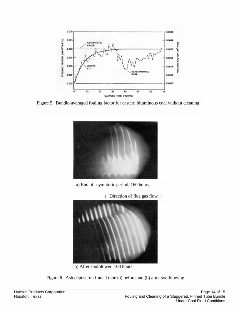
The asymptotic value is reached when the deposition and re-entrainment rates are equal. Using the solution tothe preceding equation that was presented by Kern and Seaton (1958), the asymptotic data for the bituminouscoal were curve fit using a weighted, least-squares method (Figure 5):
( )( )( )( )[ ]872872 1003501ft-hr 01970 ./t./tf eW/Km.eBtu/F.R −− −−−−= (12)
From the curve fit, the asymptotic fouling factor was about 0.0197 hr-ft2-F/Btu (0.0035m2-K/W). The timeconstant (7.8 hours) was the time required for the fouling factor to reach about 63% of the asymptotic value.
The uncertainty in fouling-factor results was estimated from the combination and propagation of uncertaintiesthrough the measurement system and calculation routines. The uncertainty was predicted to be less than ±25%for the results presented. Biased uncertainty was reduced because fouling factor is a relative parameter bydefinition, i.e., the difference between bundle thermal resistances under fouled and clean conditions. Randomuncertainty was reflected by bundle heat balances. The difference between the rates of heat lost by the flue gasand gained by the air was less than 7% for all data points.
Photographs that show ash deposition on a finned tube just before and after sootblowing were obtained duringtesting of the bituminous coal (Figure 6). The deposit prior to sootblowing had accumulated during theextended period without sootblowing and corresponds to the asymptotic fouling factor. The depositsaccumulated primarily on the downstream side of the tube and were dry and friable. Sootblowing almostcompletely cleaned the tubes, demonstrating that the cleaning process is effective.
Comparing results from other investigators adds confidence in the present work. Fouling results reported byPortyanko, et al., (1980) agree well with present results, assuming the former are asymptotic results. A foulingfactor of 0.0227 hr-ft2-F/Btu (0.0040 m2-K/W) was obtained by Portyanko, compared to 0.0197 hr-ft2-F/Btu(0.0035 m2-K/W) for the present work. The test bundles were similar, although the present bundle had 2.4times more finned surface area per tube for the same tube diameter than that tested by Portyanko. Additional finarea is expected to increase the asymptotic fouling factor. Countering this effect, gas velocity in the presentbundle was 2.9 times greater, which is expected to decrease the fouling factor. Fly ash loading and sizedistribution were not reported by Portyanko.
Observations reported by Lokshin, et al, (1980) are also consistent with the present study for staggered bundleswith similar tube pitches and diameters and identical gas velocities. In both studies, most deposition occurredbetween fins in about an 80-degree sector on the downstream side of the tubes, and little deposition occurredaround the stagnation point. The relation between fouling factor and fin surface area is also consistent. As withthe bundle tested by Portyanko, fin area per tube in the present bundle is 2.4 times greater than that in Lokshin'sbundles for the same tube diameter, and the asymptotic fouling factor for the present bundle is between 2.9 and5.3 times greater than those reported by Lokshin. No plugging between tubes was reported.
Weierman (1982) compiled fouling factors for extended surfaces in various fossil fuel flue gases. For coal, hereported a fouling-factor range between 0.005 and 0.05 hr-ft2-F/Btu (0.0009 and 0.009 m2-K/W) for a findensity between 2.9 and 4.3 fins per inch (1 fin per 5.9 to 8.6 mm), with the provision that cleaning devices areused. Results from the present study for both test coals are in this range, although the gas velocity for thepresent work was about half the velocity reported by Weierman. Additional, related work was compiled byMarner (1990).
Data for at least three fouling and cleaning cycles were obtained to demonstrate the cleanability of the bundleand to verify that the statistical curve fit of the asymptotic data was representative. Results for 4- and 8-hoursootblowing intervals were obtained. Results are shown in Figures 7 and 8 for the bituminous and

Hudson Products Corporation Page 8 of 15Houston, Texas Fouling and Cleaning of a Staggered, Finned Tube Bundle
Under Coal Fired Conditions
sub-bituminous coals, respectively. Note that between one-half and one hour was required to operate bothsootblowers and acquire steady data before and after each sootblowing operation. Results show that the foulingfactor consistently returned to zero after sootblowing every 4 to 8 hours. Some fluctuation in the data did occur,especially during the 8-hour intervals for the bituminous coal. The cycle data agree reasonably well with theempirical predictions based on the asymptotic data. This provides confidence in using the curve fit to predictfouling factors.
The effect of fouling and cleaning on bundle pressure drop is summarized in Figure 9 for the two test coals.Pressure drop is represented by the dimensionless flow loss coefficient, which is plotted versus elapsed testtime. No dramatic increase in the coefficients was observed during the tests; this would have indicated that thebundle was plugging. In fact, the loss coefficient for the bituminous coal actually tended to decrease during thetest period without cleaning. The decrease was probably a result of streamlining of the finned tubes by depositson the downstream sides of the tubes. The predicted uncertainty in the flow loss coefficient was less than 112%.
These fouling-factor results were correlated with bundle arrangement, fin geometry, ash loading, flue gasvelocity, and ash mass mean diameter. The correlation has a theoretical and empirical basis and provides apowerful design tool for predicting fouling factors for sizing heat transfer surfaces in coal-fired environments.
CONCLUSIONS
Based on the preceding results for the staggered, helically finned tube bundle in the coal-fired test environment,we conclude that:
• Fouling factor and flow loss coefficient were controllable via standard sootblowing practices.
• Bundle plugging did not occur even when the fouling factor approached its asymptotic value.
• Fouling and cleaning were well enough behaved and repeatable for mathematical correlation.
• The maximum fouling factor depended on the sootblowing frequency.
Further work is necessary to confirm for potential users the design for coal-fired fouling applications. Additionallaboratory tests have been completed with other bundle geometries and test conditions, including operationbelow the acid-dew-point temperature. The next logical activity would be to investigate the performance of aprototype, staggered, finned tube bundle on a coal-fired utility boiler. The effect of actual operating conditionswould be evaluated, including different fuels, combustion conditions, flyash conditions and temperature ranges.
REFERENCES
Bemrose, C.R., and Bott, T.R., 1984, "Correlations for Gas-Side Fouling of Finned Tubes," Institute ofChemical Engineers Symposium, Series No. 86, Vol. 1, EFCE Event n 308, Rugby, England, pp. 357-367.
Kern, D.Q., and Seaton, PLE., 1958, "A Theoretical Analysis of Thermal Surface Fouling," paper presented atSymposium on Air-Cooled Heat Exchangers, AlChE 51st Annual Meeting, Cincinnati, Ohio.
Lokshin, V.A-, Fomina, V.N., Pavlov, N.V., Portyanko, A.A., and Skornyakova, L.G., 1980, "ExperimentalInvestigation of the Fouling of Transversely Finned Bundles of Tubes in a Dust-Laden Air Flow," ThermalEngineering, Vol. 27, No. 6, pp. 327-330.
Hudson Products Corporation Page 9 of 15Houston, Texas Fouling and Cleaning of a Staggered, Finned Tube Bundle
Under Coal Fired Conditions
Marner, W.J., 1990, "Progress in Gas-Side Fouling of Heat Transfer Surfaces," Applied Mechanics Reviews,Vol. 43, pp. 35-66.
Portyanko, A.A., Lokshin, V.A., and Fomina, V.N., 1980, "The Fouling of Transversely Swept Bundles ofTubes with Welded Spiral Finning," Thermal Engineering, Vol. 27, No. 12, pp. 711-713.
Taborek, J., Aoki, T., Ritter, R., Palen, J., and Knudsen, J., 1972a, "Fouling- The Major Unresolved Problem inHeat Transfer," Chem. Eng. Prog., Vol. 68, No. 2, pp. 59-67.
Taborek, J., Aoki, T., Ritter, R., Palen, J., and Knudsen, J., 1972b, 'Predictive Methods for Fouling Behavior,"Chem. Eng. Prog., Vol. 68, No. 7, pp. 6978.
Weierman, R.C., 1982, "Design of HeatTransfer Equipment for Gas-Side Fouling Service," Workshop on anAssessment of Gas-Side Fouling in Fossil Fuel Exhaust Environments, Marner, W.J., and Webb, R.L., eds.,Publication 82-67, Jet Propulsion Laboratory, California Institute of Technology, Pasadena, Calif.
Hudson Products Corporation Page 10 of 15Houston, Texas Fouling and Cleaning of a Staggered, Finned Tube Bundle
Under Coal Fired Conditions
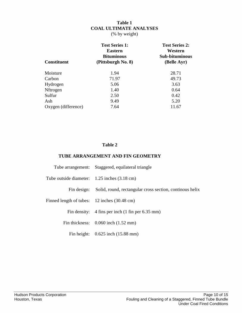
Table 1COAL ULTIMATE ANALYSES
(% by weight)
Test Series 1: Test Series 2:Eastern Western
Bituminous Sub-bituminousConstituent (Pittsburgh No. 8) (Belle Ayr)
Moisture 1.94 28.71Carbon 71.97 49.73Hydrogen 5.06 3.63Nftrogen 1.40 0.64Sulfur 2.50 0.42Ash 9.49 5.20Oxygen (difference) 7.64 11.67
Table 2
TUBE ARRANGEMENT AND FIN GEOMETRY
Tube arrangement: Staggered, equilateral triangle
Tube outside diameter: 1.25 inches (3.18 cm)
Fin design: Solid, round, rectangular cross section, continous helix
Finned length of tubes: 12 inches (30.48 cm)
Fin density: 4 fins per inch (1 fin per 6.35 mm)
Fin thickness: 0.060 inch (1.52 mm)
Fin height: 0.625 inch (15.88 mm)
Hudson Products Corporation Page 11 of 15Houston, Texas Fouling and Cleaning of a Staggered, Finned Tube Bundle
Under Coal Fired Conditions
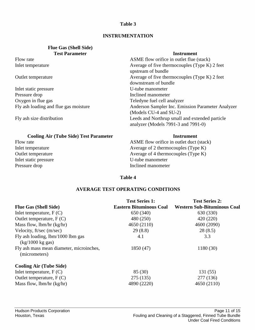
Table 3
INSTRUMENTATION
Flue Gas (Shell Side)Test Parameter Instrument
Flow rate ASME flow orifice in outlet flue (stack)Inlet temperature Average of five thermocouples (Type K) 2 feet
upstream of bundleOutlet temperature Average of five thermocouples (Type K) 2 feet
downstream of bundleInlet static pressure U-tube manometerPressure drop Inclined manometerOxygen in flue gas Teledyne fuel cell analyzerFly ash loading and flue gas moisture Anderson Sampler Inc. Emission Parameter Analyzer
(Models CU-4 and SU-2)Fly ash size distribution Leeds and Northrup small and extended particle
analyzer (Models 7991-3 and 7991-0)
Cooling Air (Tube Side) Test Parameter InstrumentFlow rate ASME flow orifice in outlet duct (stack)Inlet temperature Average of 2 thermocouples (Type K)Outlet temperature Average of 4 thermocouples (Type K)Inlet static pressure U-tube manometerPressure drop Inclined manometer
Table 4
AVERAGE TEST OPERATING CONDITIONS
Flue Gas (Shell Side)Test Series 1:
Eastern Bituminous CoalTest Series 2:
Western Sub-Bituminous CoalInlet temperature, F (C) 650 (340) 630 (330)Outlet temperature, F (C) 480 (250) 420 (220)Mass flow, lbm/hr (kg/hr) 4650 (2110) 4600 (2090)Velocity, ft/sec (m/sec) 29 (8.8) 28 (8.5)Fly ash loading, lbm/1000 lbm gas (kg/1000 kg gas)
4.1 3.3
Fly ash mass mean diameter, microinches, (micrometers)
1850 (47) 1180 (30)
Cooling Air (Tube Side)Inlet temperature, F (C) 85 (30) 131 (55)Outlet temperature, F (C) 275 (135) 277 (136)Mass flow, lbm/hr (kg/hr) 4890 (2220) 4650 (2110)
Hudson Products Corporation Page 12 of 15Houston, Texas Fouling and Cleaning of a Staggered, Finned Tube Bundle
Under Coal Fired Conditions
Figure 1. Fouling and cleaning test facility.
Figure 2. Staggered, finned tube test bundle (side view).

Hudson Products Corporation Page 13 of 15Houston, Texas Fouling and Cleaning of a Staggered, Finned Tube Bundle
Under Coal Fired Conditions
Figure 3. Bundle-averaged fouling factor for eastern bituminous coal.
Figure 4. Bundle-averaged fouling factor for western bituminous coal.
Hudson Products Corporation Page 14 of 15Houston, Texas Fouling and Cleaning of a Staggered, Finned Tube Bundle
Under Coal Fired Conditions
Figure 5. Bundle-averaged fouling factor for eastern bituminous coal without cleaning.
a) End of asymptotic period, 160 hours
↓ Direction of flue gas flow ↓
b) After sootblower, 168 hours
Figure 6. Ash deposit on finned tube (a) before and (b) after sootblowing.

Hudson Products Corporation Page 15 of 15Houston, Texas Fouling and Cleaning of a Staggered, Finned Tube Bundle
Under Coal Fired Conditions
Figure 7. Fouling and cleaning cycles for easternbituminous coal.
Figure 8. Fouling and cleaning cycles for westernsub-bituminous coal.
Figure 9. Flue gas flow loss coefficients.