Embed Size (px)
Citation preview
16707 E. Euclid Ave. | Spokane Valley, WA 99216-1816 www.cruxsub.com B 509-892-9409 | 1-866-278-9782 | F 509-892-9408
Page 1 of 4
Foundation Design Minimizes Environmental Impact
Authors: Chih-Hung Chen, PE, Burns & McDonnell, Kansas City. MO USA Nickolas G. Salisbury, President Crux Subsurface Inc., Spokane Valley, WA USA
Published By: Excerpt of this article appeared in T&D World
Date: September 2011
Crux Subsurface, Inc. Page 2 of 4
Contents
Abstract ................................................................. 2
Introduction ............................................................ 3
Design Selection ..................................................... 3
Technical Challenges ............................................... 4
Abstract Transmission line projects are facing higher levels of scrutiny than ever before, and the Tehachapi Renewable Transmission Project is no exception. The new 500 kV line crosses the Angeles National Forest, where The U.S. Forest Service has strict requirements regarding land disturbance. An innovative design solution helped owner Southern California Edison gain approval for the project. Standard drill shaft foundations were considered in the initial design phases, but involved construction elements that did not comply with environmental restrictions. Helicopter-supported micropile foundations were selected as the optimal alternative. This paper will discuss the foundation design selection process, as well as technical challenges encountered during implementation. Basic advantages of micropile foundations will also be illustrated, including minimized impacts and the ability to adapt to individual site conditions.
Crux Subsurface, Inc. Page 3 of 4
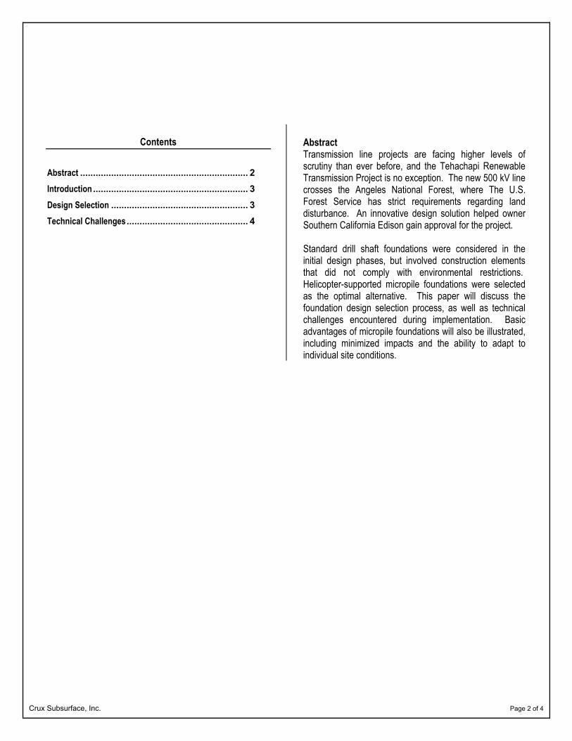
Introduction For construction within the Angeles National Forest, the U.S. Forest Service requires minimal disturbance of the land. An unconventional design and construction solution helped SCE gain approval from the U.S. Forest Service. Micropile foundations, a high-capacity version of solutions sometimes known as pin piles or mini piles because of their small diameter, also provided cost and schedule advantages over other designs because of restrictions imposed by working within the forest. Design Selection The initial design for the TRTP included a typical drill shaft foundation, which would require miles of access roads for drilling and construction equipment. Within the forest, access roads were not approved. Hand-digging would be a high-cost, inefficient method for the shafts, which would range from 42 to 72 inches in diameter and 15 to 30 feet in depth. Hand-dug excavations create worker safety hazards that are difficult to mitigate in the eyes of contractors and the Occupational Safety and Health Administration. Explosives were not an option because of the risk and environmental disturbance. The use of micropile foundations enables the construction of transmission towers with a smaller overall footprint, disrupting less of the sensitive forest environment.
Several alternatives, including prestressed or post-tensioned rock anchors and micropile foundations, were considered. Rock anchor foundations, which use anchors to resist uplift and utilize bearing between concrete cap and rock to resist foundation rotation, compression, and shear loads, were deemed impractical because of the highly variable near-surface rock and soil conditions.
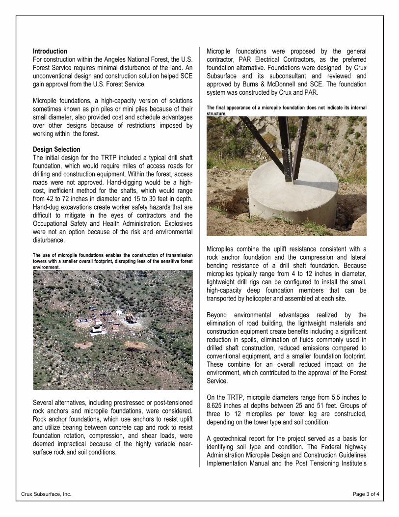
Micropile foundations were proposed by the general contractor, PAR Electrical Contractors, as the preferred foundation alternative. Foundations were designed by Crux Subsurface and its subconsultant and reviewed and approved by Burns & McDonnell and SCE. The foundation system was constructed by Crux and PAR. The final appearance of a micropile foundation does not indicate its internal structure.
Micropiles combine the uplift resistance consistent with a rock anchor foundation and the compression and lateral bending resistance of a drill shaft foundation. Because micropiles typically range from 4 to 12 inches in diameter, lightweight drill rigs can be configured to install the small, high-capacity deep foundation members that can be transported by helicopter and assembled at each site. Beyond environmental advantages realized by the elimination of road building, the lightweight materials and construction equipment create benefits including a significant reduction in spoils, elimination of fluids commonly used in drilled shaft construction, reduced emissions compared to conventional equipment, and a smaller foundation footprint. These combine for an overall reduced impact on the environment, which contributed to the approval of the Forest Service. On the TRTP, micropile diameters range from 5.5 inches to 8.625 inches at depths between 25 and 51 feet. Groups of three to 12 micropiles per tower leg are constructed, depending on the tower type and soil condition. A geotechnical report for the project served as a basis for identifying soil type and condition. The Federal highway Administration Micropile Design and Construction Guidelines Implementation Manual and the Post Tensioning Institute’s
Crux Subsurface, Inc. Page 4 of 4
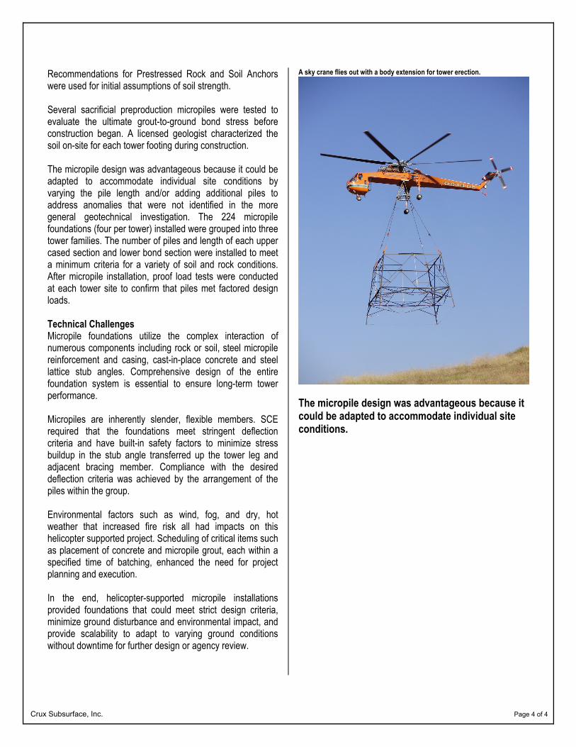
Recommendations for Prestressed Rock and Soil Anchors were used for initial assumptions of soil strength. Several sacrificial preproduction micropiles were tested to evaluate the ultimate grout-to-ground bond stress before construction began. A licensed geologist characterized the soil on-site for each tower footing during construction. The micropile design was advantageous because it could be adapted to accommodate individual site conditions by varying the pile length and/or adding additional piles to address anomalies that were not identified in the more general geotechnical investigation. The 224 micropile foundations (four per tower) installed were grouped into three tower families. The number of piles and length of each upper cased section and lower bond section were installed to meet a minimum criteria for a variety of soil and rock conditions. After micropile installation, proof load tests were conducted at each tower site to confirm that piles met factored design loads. Technical Challenges Micropile foundations utilize the complex interaction of numerous components including rock or soil, steel micropile reinforcement and casing, cast-in-place concrete and steel lattice stub angles. Comprehensive design of the entire foundation system is essential to ensure long-term tower performance. Micropiles are inherently slender, flexible members. SCE required that the foundations meet stringent deflection criteria and have built-in safety factors to minimize stress buildup in the stub angle transferred up the tower leg and adjacent bracing member. Compliance with the desired deflection criteria was achieved by the arrangement of the piles within the group. Environmental factors such as wind, fog, and dry, hot weather that increased fire risk all had impacts on this helicopter supported project. Scheduling of critical items such as placement of concrete and micropile grout, each within a specified time of batching, enhanced the need for project planning and execution. In the end, helicopter-supported micropile installations provided foundations that could meet strict design criteria, minimize ground disturbance and environmental impact, and provide scalability to adapt to varying ground conditions without downtime for further design or agency review.
A sky crane flies out with a body extension for tower erection.
The micropile design was advantageous because it could be adapted to accommodate individual site conditions.